1
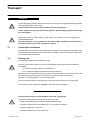
Operating Instructions
H – R 259 en 12.04
Three–phase motors with squirrel cage for high voltage,
with antifriction bearings
AJSA–315..–..
AHSA-355..–.. to 560..-..
AHRA-630..–.. to 800..-..
AHWA-355..–.. to 560..-..
JHSA–315..-.. to 800..-..
JHRA–500..-.. to 800..-..
JHWA–355..-.. to 800..-..
LOHER GmbH
P.O. Box 1164 • 94095 RUHSTORF
Hans–Loher–Str. 32 • 94099 RUHSTORF
GERMANY
Phone +49 8531 39–0 • Fax +49 8531 32895
E–Mail: [email protected]
http://www.loher.de
Table of contents
Page
1.
Safety and commissioning instructions. . . . . . . . . . . . . . . . . . . . . . . . . . .
2
2.
Description . . . . . . . . . . . . . . . . . . . . . . . . . . . . . . . . . . . . . . . . . . . . . . . . . . . 5
3.
Transport . . . . . . . . . . . . . . . . . . . . . . . . . . . . . . . . . . . . . . . . . . . . . . . . . . . .
7
4.
Installation and commissioning . . . . . . . . . . . . . . . . . . . . . . . . . . . . . . . . . . .
8
5.
Maintenance . . . . . . . . . . . . . . . . . . . . . . . . . . . . . . . . . . . . . . . . . . . . . . . . . .13
6.
Additional equipment . . . . . . . . . . . . . . . . . . . . . . . . . . . . . . . . . . . . . . . . . . . 16
7.
Spare parts. . . . . . . . . . . . . . . . . . . . . . . . . . . . . . . . . . . . . . . . . . . . . . . . . . 17
8.
Storage instructions . . . . . . . . . . . . . . . . . . . . . . . . . . . . . . . . . . . . . . . . . . . . 18
9.
Faults and remedies . . . . . . . . . . . . . . . . . . . . . . . . . . . . . . . . . . . . . . . . . . . 22
Appendix 1; Alignment check . . . . . . . . . . . . . . . . . . . . . . . . . . . . . . . . . . . . 23
Subject to modifications
©Loher GmbH 2004
All rights reserved
H–R 259 en 12.04
Page 1 of 23
Safety and commissioning instructions
1.
Safety symbols in these instructions
1.1
Safety symbols in these instructions
The symbols are used in this user manual in order to draw attention to special dangers.
This symbol indicates a dangerous situation. Fatal or serious injuries or larger material damage
can result.
Danger
This symbol shows a situation that may be dangerous. If not avoided, injuries or material damage
may result.
1.2
General
Danger
1.3
High–voltage machines rated at more than 1 kV have dangerous live and rotating parts and may
have hot surfaces. All operations serving transport, connection, putting into service and maintenance shall be carried out by responsible skilled persons (in conformity with EN 50 110–1 / DIN
/ VDE 0105; IEC 60364). Improper handling may cause serious personal injury and damage to
property. Danger!
Intended use
These high–voltage machines are intended for industrial installations. They comply with the harmonized standards of the series EN 60034 / DIN VDE 0530. Their use in hazardous areas is prohibited unless they are expressly designed for such use (follow supplementary instructions).
On no account, use degrees of protection ≤ IP 23 outdoors.
Air–cooled models are designed for ambient temperatures of –20°C up to 40°C and altitudes of
≤ 1000 m above sea level. Ambient temperature for air–/water–cooled models should be not less
than +5°C (for sleeve–bearing machines, see manufacturer’s documentation). By all means, take
note of deviating information on rating plate. Field conditions must conform to all rating plate particulars.
High–voltage machines are components for installation in machinery within the meaning of the
Machinery Directive 98/37/EC. Putting into service is prohibited until conformity of the
end product with this directive has been established (follow particular local safety and installation
rules as e.g. EN 60204).
1.4
Transport, Storage
Immediately report damage established after delivery to transport company. If appropriate, prevent putting into service of machine. Eyebolts are dimensioned for the weight of the high–voltage
machine, do not apply additional loads. If necessary, use suitable, adequately dimensioned
means of transport (e.g. rope guides). Remove shipping brace (e.g. antifriction or sleeve bearing
locks, vibration dampers) before putting machine into service. Reuse it for further transports.
When storing high–voltage machines, make sure of dry, dust–free and low–vibration
(Vrms ≤ 0.2 mm/s) location (danger of bearing damage at rest). Measure insulation resistance before putting machine into service. With values of v 4⋅(UN [kV]+1) [MΩ] at 20°C winding temperature, dry the winding.
Refer to the section ”Storage regulations”.
Page 2 of 23
H–R 259 en 12.04
Safety and commissioning instructions
1.5
Danger
Installation
Make sure of even support, solid foot or flange mounting and exact alignment in case of direct
coupling. Avoid resonances with rotational frequency and double mains frequency as a result of
assembly. Turn rotor, listen for abnormal slip noises.Check direction of rotation in uncoupled
state (refer to the section ”Electrical connection”).
Mount or remove couplings or other drive elements only with appropriate means (heat!) and cover
them with touch guard. Avoid excessive radial and axial bearing loads (note manufacturer’s documentation). The balance of the high–voltage machine is indicated (H = Half, F = Full key). With
half–key models, the coupling, too, must be half–key balanced. In case of protruding, visible part
of key, establish mechanical balance.
Make necessary ventilating pipe connections. Models with shaft ends pointing upward to be provided with cover by customer. The ventilation must not be obstructed and the exhaust air, also
of neighbouring sets, not taken in directly.
1.6
Electrical connection
All operations must be carried out only by skilled persons on the high–voltage machine at rest.
Before starting work, the following five safety rules must be strictly applied:
Danger
– De–energize!
– Provide safeguard against reclosing!
– Verify safe isolation from supply!
– Connect to earth and short!
– Cover or provide barriers against neighbouring live parts!
De–energize auxiliary circuits (e.g. anti–condensation heating).
Exceeding of limit values of zone A in EN 60034–1/DIN VDE 0530–1 – voltage ± 5%,
frequency ± 2%, form and symmetry – leads to higher temperature rise. Note rating plate particulars and connection diagram in terminal box.
The connection must be so made that permanently safe electrical continuity is maintained. Use
appropriate cable terminations.
Establish and maintain safe equipotential bonding.
The clearances between uninsulated, live parts and between such parts and earth must not be
below the following values: 36 mm at UN ≤ 3.3 kV, 60 mm at UN ≤ 6.6 kV, 100 mm at UN ≤ 11 kV.
No presence of foreign bodies, dirt or moisture is allowed in the terminal box. Close unused cable
entrance holes and the box itself in a dust– and watertight manner. For trial run without output
elements, lock fitting key.
For high–voltage machines with accessories, check satisfactory functioning of these before putting into service.
he proper installation (e.g segregation of signal and power lines, screened cables etc.) lies within
the installer’s responsibility.
If no further information is given, the torque for the contact screws and nuts should be used according to section 4.6.2.
H–R 259 en 12.04
Page 3 of 23
Safety and commissioning instructions
1.7
Operation
Danger
Vibration severities in the ”satisfactory” range (Vrms ≤ 4.5 mm/s) according to ISO 3945 are acceptable in coupled–mode operation. In case of deviations from normal operation
– e.g elevated temperature, noises, vibrations – disconnect machine, if in doubt.
Establish cause, consult manufacturer, if necessary.
Do not defeat protective devices, not even in trial run.
In case of heavy dirt deposits, clean cooling system at regular intervals. From time to time, open
closed condensate drain holes, if any.
Regrease antifriction bearing with relubricating device while high–voltage machine is running.
Follow instructions on lubricating plate.
Refer to manufacturer’s documentation for sound power level and information about the use of appropriate sound–reducing measures.
1.8
Maintenance and servicing
Follow manufacturer’s operating instructions.
Page 4 of 23
H–R 259 en 12.04
Description
2.
2.1
Description
Overall construction and design
Mounting arrangement acc. to EN 60034–7:
Horizontal arrangement
IM B3
Vertical arrangement
IM V1 or IM V10
see dimension drawing or rating plate
Connection designations acc. to
DIN VDE 530 part 8
IEC 60034 – 8:
see wiring diagram
Degree of protection acc. to
EN 60034 – 5:
see rating plate
Cooling acc. to EN 60034–6:
IC 411
surface cooling or hollow–fin cooling
IC 511
tube cooling
IC 01
internal cooling
IC 611
internal cooling with mounted–on air–to–air heat exchanger
IC 81 W
internal cooling with air–water heat exchanger
IC 71 W
water jacket cooling
Details of the motor design are indicated in the relevant technical catalogues.
2.2
Bearings
The motors are equipped with grease–lubricated antifriction bearings.
The bearings are equipped with regreasing devices and automatic grease quantity control.
2.3
Cooling
2.3.1
Surface cooling (TEFC) for the Type A.SA–... / AHRA–...
Design for fin–, hollow–fin– or tube cooling, where an external fan takes in the cooling air through
the openings in the fan cover and presses the air over the surface or through the cooling tubes of
the stator housing. In case of hollow–fin or tube cooling the heat dissipation is supported by a
closed cooling air circuit inside the motor.
2.3.2
Internal cooling for the Type JHSA–...
In case of motors with degree of protection IP 23, the cooling air (ambient air) is taken in by internal
fans through air inlet openings, led over the heat–generating elements in the motor and is blown
out through air outlets.
2.3.3
Internal cooling with mounted–on air–water heat exchanger for the Type JHWA–...
The motors are equipped with air–water circuit coolers. The cooling air led through the heat exchanger and motor is recooled in the heat exchanger and the heat loss is dissipated through the
cooling water. The heat exchangers are provided with special ribbed tubes.
2.3.4
Internal cooling with mounted–on air–to–air heat exchanger for the Type JHRA–...
The motors are equipped with air–to–air heat exchanger. The cooling air led through the heat
exchanger and motor is recooled in the heat exchanger and the heat loss is dissipated through
the cooling medium air.
2.3.5
Water jacket cooling for the Type AHWA–355..–.. to AHWA–560..–..
The stator housing has a double casing. It is sub–divided for water channelling and the cooling
water passes through. This results in a good heat dissipation. Additionally, this reduces the danger
of suspended matter carried along in the water getting deposited.
H–R 259 en 12.04
Page 5 of 23
Description
2.4
Motor frame
2.4.1
Construction for surface cooling (TEFC), hollow–fin cooling or tube cooling
(Type A.SA–...–.. / AHRA–...)
Depending on the frame size the stator frame and end shields are made of grey cast iron or steel.
The fan cover is made of sheet steel. The stator frame surface is provided with cooling fins, hollow
fins or tubes and an attached terminal box.
2.4.2
Construction for internal cooling (ODP) for the Type JHSA–...
Depending on the frame size the stator frame and end shields are made of cast iron or steel. The
stator frame has an even surface with attached terminal box. There are distance fins between
stator jacket and stator pack to facilitate the internal cooling.
2.4.3
Construction for internal cooling with air–water heat exchanger for the Type JHWA–...
The stator frame and end shields are of steel. The stator frame surface is plain with a
mounted–on terminal box. Between the stator jacket and the stator core, there are spacing ribs
to facilitate the internal cooling. An air–water circuit cooler is mounted onto the ventilation
openings.
2.4.4
Construction for internal cooling with air–to–air heat exchanger for the Type JHRA–...
Like for the internal cooling with air–water heat exchanger, however, an air–to–air heat exchanger is mounted onto the ventilation openings.
2.4.5
Construction for water jacket cooling (Type AHWA–355..–.. to AHWA–560..–..)
Stator frame and end shields are made of grey cast iron or steel.
The stator jacket is designed as double casing, through which the cooling water is led.
The housing is provided with inlet and outlet for the cooling water.
2.5
Stator winding
The stator winding is made in an insulation class (see rating plate) acc. to EN 60034–1.
High–quality enamelled wires, suitable surface insulating materials and the type of insulation
provide a high level of mechanical and electrical stability with a high utilization factor and a long
service life.
2.6
Rotor
The rotor has a hard–soldered cage.
The rotor is dynamically balanced.
The balance is indicated on the shaft end or the rating plate, see Paragraph 4.1 ”Installation”.
The motors in standard design meet the requirements of vibration level N
acc. to DIN EN 60034–14 / IEC 60034–14, in special cases level R (reduced) or S (special).
2.7
Terminal boxes
Additional connector boxes for monitoring equipment are available in addition to the motor
connection boxes. A neutral point box is only attached if ordered extra (see dimensional drawing).
The number of available terminals can be seen in the wiring diagrams.
2.8
Monitoring devices
Monitoring devices are only available on special request. See wiring diagram.
Page 6 of 23
H–R 259 en 12.04
Transport
3.
Transport
For handling during transport the stator construction of the motor is equipped with lifting eyebolts,
where the lifting hooks can be fixed.
Check whether the screwed lifting eyebolts are securely tightened.
Lift the motors only by using these lifting eyebolts. Several lifting eyebolts must always
be used together.
Slinging the motors on other parts (e.g. shaft ends) is not permitted, since this might result in
considerable damage.
The lifting eyebolts are only suitable for the motor weight. Additional loads attached to
the motor must never be lifted using these eyebolts.
3.1
Check before installation
Check whether the motor has been damaged during transport. If the packing is damaged to such
an extent that motor damage is to be assumed, the packing should be removed in the presence
of a representative of the carrier.
3.2
Bearing lock
(for motors with cylindrical roller bearings only.)
The rotor of the motor is locked in order to avoid damage to bearings caused by vibrations
at standstill:
–
by red marked locking screws in the bearing cap
–
or by a transport locking mechanism fixed to the shaft end.
Before the motor is mounted, the locking screws must be loosened by 10 mm and secured, and
the transport locking device must be removed (see instruction plate on the motor).
After this, it must be possible to turn the shaft by hand.
We recommend loosening of the bearing lock only after the drive element has been fitted.
The transport locking mechanism should be reused for further transports.
Prevent failures and thus avoid damages to persons and property.
The person responsible for the plant has to make sure, that
– safety– and operating instructions are available and observed
– operating conditions and technical data acc. to the order are observed
– protective equipment is used and
– specified maintenance work is carried out.
H–R 259 en 12.04
Page 7 of 23
Installation and commissioning
4.
Installation and commissioning
A most careful mounting and alignment of the motors on an absolutely even surface is imperative to avoid distortions when the screws are being tightened. For machines which are to be
coupled attention must be paid to careful alignment. See Appendix 1 for alignment checking.
Couplings that ara as elastic as possible should be used.
When using pulleys, toothed wheels etc., ensure that the permitted radial and axial shaft loads
are not exceeded.
The motors with surface cooling (TEFC), hollow–fin cooling or tube cooling , or internal
cooling with air–to–air heat exchanger
(for all specified types except Type AHWA–... and JHWA–...)
Maximum permissible coolant temperature (ambient temperature on site) acc. to EN 60034–1/IEC
60034–1 is 40°C (104°F) and a permissible altitude up to 1000 m above mean sea level (for other
va–lues, see rating plate).
Care must be taken that the cooling air can flow without hindrance into the air inlet openings and
freely pass through the air outlet openings and cannot be directly sucked in again. Suction and
outlet openings must be protected from obstructions and coarse dust.
Motors with water jacket cooling (Type AHWA–355..–.. to AHWA–560..–..)
Before commissioning water–cooled motors, the troublefree working of the cooling–water circuit
must be guaranteed. It must be ensured that the motor is only switched on when the cooling water
circuit is in operation. It must be kept functioning until the motor comes to standstill after switching–
off. Inlet and outlet openings are located on the motor housing.
The cooling water circuit is to be monitored. Normally, the motor is equipped with PTC thermistor
sensors, which switch off the motor if the cooling–water circuit fails. If the housing is provided with
vent plugs for the water chamber, venting should be done for the first filling and thereafter at regular
intervals.
Only clean, non–aggressive cooling water is to be used. Permissible content of suspended solids
is max. 10mg/l
The inlet temperature of the cooling water should be at least 20 °C (68 °F).
Temperatures below 20 °C (68 °F) result in higher formation of condensation water. Permissible
inlet and outlet temperature, maximum pressure and the required amount of cooling water are
indicated on the motor plates.
If the motors are run at a coolant temperature below 0 °C (32 °F), then, because of the reduced
cooling action owing to the addition of antifreeze, consultation with the motor manufacturer is
necessary.
Page 8 of 23
H–R 259 en 12.04
Installation and commissioning
The motors with mounted–on air–water heat exchanger for the Type JHWA–..
Before commissioning of the motors, the troublefree functioning of the cooling–water circuit must
be guaranteed. It must be ensured that the motor will only be switched on when the cooling–water
circuit is in operation. It must continue to work until the motor comes to standstill after switching–off.
Permissible inlet and outlet temperature, maximum pressure and the required amount of cooling
water are indicated on the motor plates.
4.1
Mounting
Fitting of pulleys or couplings.
First the shaft end should be cleaned (not with emery cloth) and then greased. The pulley or
coupling should be lifted only with the aid of a lifting device. The threaded centering hole in the shaft
end can be used for this purpose. Insert a threaded bolt into the threaded hole. Then place the steel
washer, the diameter of which is large enough to cover the hub borehole of the pulley or coupling.
The pulley and coupling is to be fitted onto the shaft end by means of a nut or coupling or a suitable
hydraulic device.
The fitting of the drive elements by means of hammer blows is not permitted because of
the risk of damage to the bearings.
When replacing the bearings, the bearings must only be removed and reinstalled by means
of suitable devices using the shaft centering. Only original spare parts must be used.
The rotor of the motor is dynamically balanced. The state of balance is indicated on the shaft end
face or the rating plate (H = half key, F = full key). Take care of the balance for installation of the
driving element!
The balancing of the transmission elements to be fitted must be adapted to the rotor balancing.
In case of half key balancing any protruding and visible part of the key must be removed or a
mechanical balance ensured.
The motor must only be mounted and operated according to the specified mounting arrangement
(see rating plate).
H–R 259 en 12.04
Page 9 of 23
Installation and commissioning
4.2
Connection, insulation resistance
Connection must only be made by an expert and in accordance with the valid safety regulations.
The relevant installation– and operating instructions as well as national and international rules have
to be observed.
Observe the data on the rating plate!
Compare type of current, mains voltage and frequency (refer to item 4.3.1).
Check the wiring diagram!
Observe the rated current for setting of the protective switch!
Connect motor in accordance with the wiring diagram provided in the terminal box!
The motor must be protected against excessive heating.
For earthing the motor is provided with an earthing terminal, which depending on the mounting arrangement is either located on the frame or on the flange end shield as the case may be. In addition,
all motors have a protective conductor terminal inside the terminal box.
As protection against dust and humidity unused cable entries in the terminal box must have a torsionproof seal. All terminal screws and nuts have to be securely tightened to avoid excessive
transition resistances (see paragraph 4.6.2).
Protective measures are to be taken.
In case of terminal boxes which have ground surfaces between cover and base a thin grease film
is to be applied for sealing and against corrosion.
High-voltage terminal boxes have a pressure-relief valve with a predetermined rupture point
(in the bottom part of the terminal box). Valve and sealing must not be damaged during
assembly and connection. The degree of protection must be guaranteed.
In case of damage, the sealing has to be renewed only with original sealing material.
In operation the terminal box must always be tightly closed.
Cable and , lead entries and connecting cables must be suitable for the ambient temperatures
that occur.
Terminal boxes with current transformer
For the use of current transformers it must be ensured that the secondary circuit of the current
transformer is protected from unintentional opening during operation.
After storage for a prolonged period or a shutdown (see 8.1.2), the insulation resistance of the
winding must be measured phase to phase and phase to earth.
Damp windings can result in leakage currents, arc–overs and blow–outs.
The insulation resistance for the windings must reach the following values:
–Stator winding y 4⋅( Ustator [kV] +1) [MW], measured at a winding temperature of 20°C.
Any overvoltage surpressors present that are connected to the motor may falsify the insulation
resistance. If there is any doubt, disconnect the overvoltage surpressors. If the insulation
resistance is lower, dry the windings (also refer to item 8.1.2).
Page 10 of 23
H–R 259 en 12.04
3.2
Installation and commissioning
4.3
Rotational direction and designation of the terminals acc. to
DIN VDE 0530–8/IEC 60034–8
4.3.1
In case of motors with only direction of rotation, the direction of rotation is marked on the motor
with an arrow. Terminals U1, V1, W1 to phases L1, L2, L3 (in alphabetical or natural order) always
results in right–handed rotation.
This applies to all motors, even if they are not suited for right–handed rotation.
4.3.2
Changing the direction of rotation:
The rotational direction can be switched by interchanging two supply lines on the motor terminal
board.
For a machine with only one shaft end or two shaft ends with different thicknesses, the direction
of rotation is that seen an observer when he views the outer face of the only shaft end or the thicker
shaft end.
4.3.3
In cas of forced ventilation, the direction of rotation is separately marked by an arrow on the forced
ventilation system itself.
4.4
Air–water heat exchanger
(motors with air–water heat exchanger of the type JHWA–...)
For connection and commissioning the instructions for air–water heat exchangers must be considered. The permissible inlet and outlet temperature, maximum pressure and the required
amount of cooling water are indicated on the motor plates.
4.5
Check before commissioning
– Check whether the bearing lock has been removed!
See Paragraph 3.2 ”Bearing lock”!
– Observe data on the rating plate!
– Check whether the voltage and frequency of the motor comply with the mains data!
– Check whether the rotational direction is correct!
– Check whether the motor is protected as specified in the regulations!
– Check whether the electrical connections are securely tightened and whether the
monitoring devices are correctly connected and adjusted!
– Visual check whether the pressure-relief valve and the sealing in the HV terminal box are
undamaged.
– Check whether protective measures have been taken: earthing!
– Check coolant temperature!
– Check whether the additional equipment – if any – is functioning.
– Check whether the cooling air inlet openings and cooling surfaces are clean!
– If a condensation water drain hole exists, open the hole for a short time, that the
accumulated condensation water can be drained off!
– Check insulation resistance of the stator winding!
– Check whether the motor is securely fixed!
– In case of a belt drive, check the belt tension!
– Check whether the cover of the terminal box is closed and whether the cable
entries are properly sealed.
– In case of water–cooled motors, check whether the cooling water circuit is in operation!
– For forced–ventilated motors it is to be checked, whether the forced ventilation is
functioning and in operation when the main motor is in operation.
H–R 259 en 12.04
Page 11 of 23
Installation and commissioning
4.6
Tightening torques for screwed joints
4.6.1
General
If no other data are indicated the following torque limits (screw and nut) are applicable.
Note:
Screws which become unusable have to be replaced by
new ones of the same strength class and type.
4.6.2
Screwed joints for electrical connections
Thread
4.6.3
Tightening torque [Nm]
Thread
Tightening torque [Nm]
M4
1.2
M 12
15.5
M5
2
M 16
30
M6
3
M 20
52
M8
6
M 24
80
M10
10
M 30
150
Screwed joints strength class 8.8 and A4–70
Tightening torques for screws of the strength class 8.8 and A4–70 (A4–80) only in components
with higher strength (e.g. grey cast iron, steel).
Thread
4.6.4
Tightening torque [Nm]
Thread
Tightening torque [Nm]
M4
2.3
M 14
105
M5
4.6
M 16
160
M6
7.9
M 20
330
M8
19
M 24
560
M10
38
M 30
1100
M 12
66
M 36
1900
Screwed joints strength class 5.6
Tightening torques for screws of the strength class 5.6, 4.6, A2 or for screws in components
with lower strength (e.g. aluminium).
Thread
Page 12 of 23
Tightening torque [Nm]
Thread
Tightening torque [Nm]
M4
1.1
M 14
49
M5
2.1
M 16
75
M6
3.7
M 20
150
M8
8.9
M 24
260
M10
18
M 30
520
M 12
30
M 36
920
H–R 259 en 12.04
Maintenance
5.
Maintenance
The person responsible for the facility must ensure that the specified maintenance work
is carried out properly.
5.1
Bearings and greasing
5.1.1
The bearings of the motors are equipped with regreasing devices and automatic grease quantity control. The regreasing of the bearings is done by means of a grease gun through the
nipples provided on the end shields.
Overfilling of the bearing chambers is not possible since in case of an extended regreasing the
used grease will be thrown off by a rotating disk in the outer grease chamber through an aperture in the bearing cap (or into a grease collecting chamber).
Regreasing during operation only!
Danger of accident! Pay attention to rotating parts.
Regreasing intervals, grease quantity and grease quality are indicated on the instruction plates on
the motor. Regreasing, however, is to be one at least once a year. Clean the lubricating nipples.
If the motor is equipped with grease removal rams, the used grease must be removed after regreasing by pulling the ram at the bearing several times up to the limit stop while the motor is in
operation.
If the motor is equipped with grease collecting chambers, these chambers are to be dismounted
at motor standstill acc. to the intervals on the instruction plate and the used bearing grease is to
be removed. If this is not done, the grease piles up and the bearings get overheated.
Extending the regreasing intervals endangers the bearing and might risk a deterioration of the
sealing provided by the grease and thus the ingress of dust into the bearing. If the motors have
not been operated for a prolonged period, we recommend, even for new motors, regreasing the
bearings before putting into operation, especially if, due to congealing of grease in the bearing,
there are noises which are caused by vibrations of the bearing cage. During the running–in,
increased bearing noises might occur for a short period. The bearing noise is not critical as long
as the operating temperature of the bearing is not yet reached and if the noise is caused by the
viscosity and the dynamic viscosity of the bearing grease.
The temperature of the bearings is continuously to be checked. Up to an ambient temperature of
40 °C/104 °F a heating–up of 80 K is acceptable if the recommended grease quality is used.
H–R 259 en 12.04
Page 13 of 23
Maintenance
We would like to point out that the grease quantity regulation can only work properly if the grease
types specified by us are used. The plate fixed on the motor is decisive here!
Relubrication with grease of a different saponification basis. e.g. sodium saponified grease,
might cause a deterioration and elimination of the grease effect and thus a total damage of the
bearings.
In case of 2 and 4–pole motors, it might happen that by the use of unsuitable grease, the grease
quantity regulation fails and when pressing new grease into the bearings, they get abnormally hot
due to overfilling. In such cases the bearings have to be cleaned thoroughly by using cold–
degreasing agent, and refilled with suitable grease.
5.1.2
Avoiding of mechanical damage (bearing damage)
All machines have to be checked at regular intervals for mechanical damages.
Special attention must be paid to ensure that the intervals for bearing replacement and
regreasing intervals or grease change intervals as well as oil change intervals to be specified
by the user are observed.
When the rated service life is reached the bearings should either be replaced or it must be
proven, in an inspection, that there is no mechanical damage.
– For bearings which are not regreasable it is ensured that the rated service life will only be
reached clearly after the grease service life of the bearings is reached.
– The calculated rated service life of the bearings can be seen in the data sheet of the machine, if it was specified particularly or for structural reasons specified for an individual case.
– For machines which are exposed to forces applied externally (e.g. belt force or axial load
from the driven machine) the bearing service life is a minimum of 20.000 hours for the full load
indicated in the technical list.
– All of the other machines have a rated bearing service life of at least 40.000 hours.
– For bearings with a separate oil supply, the user must suitably monitor the lubrication to
ensure that it maintained.
Page 14 of 23
H–R 259 en 12.04
Maintenance
5.2
Terminal locations, terminals, ventilating passages
Depending on the operating conditions, the following should be done at certain intervals
– checking the cleanliness of terminal locations and terminals
– checking of the electrical connections with regard to tightness
(see Paragraph 4.6.2 for tightening torques).
– cleaning of the ventilating passages.
Both the cooling air inlets and the cooling surfaces must be protected against obstruction and
contamination.
– If required, the water chambers are to be flushed and cleaned of deposits.
Never use sharp–edged tools for cleaning.
5.3
Air–water heat exchanger
(Motors with air–water heat exchanger of the Type JHWA–...)
For maintenance, please comply with the specifications for the air–water heat exchangers.
5.4
Condensation water drain hole
If the motor has a condensation water drain hole, it has to be opened at regular intervals to allow
the accumulated condensation water to drain.
Attention must be paid to always seal the condensation water drain hole by a screw with lock
washer, so that the degree of protection is assured.
H–R 259 en 12.04
Page 15 of 23
4.2
Additional equipment
6.
Additional equipment
On special order only.
6.1
Temperature monitoring *)
The temperature sensors for monitoring e.g. the stator winding temperature, the bearings, the
coolant must be connected by one or several additional terminal boxes.
The temperature sensors have to be connected according to the relevant connection diagram.
The specifications and instructions acc. to Paragraph 4.2 ”Connection” are applicable to the
connections.
6.2
Space heater *)
Heating capacity and connection voltage: See special plate on the motor. The space heater has
to be connected by an additional terminal box acc. to the relevant connection diagram.
The specifications and instructions acc. to Paragraph 4.2 “Connection” are applicable to the
connections. Operation of the space heater is only allowed when the motor is switched off. The
space heater must never be switched on during motor operation.
6.3
Forced ventilation *)
Observe direction of rotation! (see arrow for directional rotation.)
Forced ventilation is to be connected acc. to the wiring diagram inside the terminal box.
During operation of the main motor, the forced ventilation motor must be switched on!
The forced ventilation is dissipating the heat loss during operation of the main motor. When
switching off the main motor, a temperature–dependant continuation of the forced ventilation is
required.
6.3.1
To be checked when commissioning the main motor:
Check whether the forced ventilation works and is in operation when the main motor is
switched on!
*) On special order only
Page 16 of 23
H–R 259 en 12.04
Spare parts
7.
Spare parts and components
When ordering spare parts, please state:
Spare part designation
Motor type
Serial number
Example:
End shield DE
AHSA–400LM-04A
5 036 228
Type and serial number of the motor can be taken from the rating plate.
H–R 259 en 12.04
Page 17 of 23
Storage instructions
8.
Storage specifications
8.1
For motors which have to be stored for a period of up to 2 years, the following is to be observed:
8.1.1
Storage
8.1.1.1
The motors must be stored dry, dustfree and at room temperature. In this case no special packing
is required. Otherwise the motors must be packed in plastic foil with hygroscopic substances (e.g.
Branogel) or in an air–sealed foil. Protective cover must be provided against sun and rain.
8.1.1.2
In order to avoid secondary failures at the bearings caused by vibrations at standstill, for example
by adjacent running machines, the motors are only allowed to be stored in vibrationless rooms.
8.1.1.3
Motors with roller bearings are equipped with a bearing lock at the driving end. It is to remain locked
until commissioning or to be reinstalled after an inspection or a trial operation. A locking device is
not necessary and not present, if the bearing is axially preloaded.
8.1.1.4
On motors with sealed condensation water drain holes it might be necessary to have the condensation water flow out. Afterwards the boreholes are to be sealed again.
8.1.2
Commissioning
8.1.2.1
Before commissioning the insulation resistance of the winding must be measured by qualified
personnel phase to phase and phase to ground. Damp windings may cause leakage currents, arcing and ruptures. In case of values v 4 · (UN [kV] +1) [MΩ] measured at a winding temperature
of 20°C (68°F) the winding must be dried. Drying is possible by passing a single–phase AC current
through the winding. The voltage has to be adjusted in such a way that the recommended values
of the heating current in accordance with Illustrations a) and b) are not exceeded.
The temperature should reach approx. 80°C (176°F) and be in effect for several hours. Drying is
also possible in a drying kiln.
Page 18 of 23
H–R 259 en 12.04
Storage instructions
Recommended heating circuits and maximum heating currents
a) D
IMAX = 65 % Ir
b) Y
IMAX = 75 % Ir
8.1.2.2
In the case of motors with bearing lock, the bearing lock this one has to be removed before commissioning.
8.1.2.3
Antifriction bearings, lubrication
If adequately stored for a prolonged time, it can be assumed that for 2 years, the lubricating grease
in the bearings is not affected.
For motors with insulation class F a lithium–saponified antifriction bearing grease with a dripping
point of at least 180 °C (356 °F) is used for normal ambient temperatures.
For the motors with insulation class H and for certain special motors, the special lubricating grease
used is indicated on an instruction plate attached to the motor.
8.1.2.4
For motors with a regreasing device it is advisable to regrease both bearings shortly after commissioning with the motor running.
The grease type, grease quantity and regreasing intervals are marked on an additional plate fixed
on the motor.
The values for grease service life with regreasing intervals can surely be expected for motors with
degree of protection IP 55. The bearing is protected against the ingress of fine dust and of water
in all directions, e.g. for outdoor installation without additional protection.
For motors with degree of protection IP 44 and IP 54 these data apply with the restriction that the
environmental load by dust and water is not exceeding the limits of DIN EN 60034–5 with tests
according to DIN EN 60034–5.
8.1.3
For motors which are transported and stored in assembled condition with the machine
to be driven the following must be observed:
8.1.3.1
Storage
a) The free shaft ends must be greased before installation of the motors also all of the other
exposed metal parts, e.g. foot- and flange surfaces or supporting faces of terminal boxes and
covers. As protection against dust and humidity grease seals with antifriction bearing grease are
to be in–stalled at the shaft opening.
b) A hygroscopic substance (e.g. Branogel) is to be filled into the terminal boxes of the motors.
c) The machines are to be stored dry, dustfree and in a temperature–controlled room.
d) For further measures, the specifications according to the items 8.1.1.2 – 8.1.1.4 are applicable.
H–R 259 en 12.04
Page 19 of 23
Storage instructions
8.1.3.2
Commissioning
Before commissioning the hygroscopic substance (e.g. Branogel) must be removed from the
terminal boxes and the measures according to 8.1.2 carried out.
8.1.3.3
For outdoor storage, the following needs to be done in addition:
Protective cover against the influence of sun and rain must be provided: exchange of air must be
possible to avoid condensation water.
After 2 months it must always be checked if the protective measures acc. to 8.1.3.1a are still given
and functioning.
8.2
For motors which are stored for more than 2 up to 4 years before commissioning, the following additionally applies:
8.2.1
Storage
8.2.1.1
The manufacturer must be informed about the storage duration in the purchase order.
8.2.1.2
The shaft opening and terminal box cover must be provided with grease seals of antifriction bearing
grease. The motor shafts are not allowed to be rotated before commisioning, as otherwise the protective grease coating is destroyed. If movement of rotating parts is unavoidable, the protective
grease coating has to be applied afresh.
8.2.1.3
A hygroscopic substance (e.g. Branogel) must be put in the terminal boxes.
8.2.2
Commissioning
8.2.2.1
Before commissioning the hygroscopic substance (e.g. Branogel) must be removed from the
terminal boxes and the measures according to 8.1.2 are to be carried out.
8.2.2.2
Antifriction bearings, lubrication
Motors with a regreasing device must be relubricated immediately after commissioning with about
the double grease quantity, until the used grease has been thrown out. Further greasing can then
be done with the bearing grease indicated on the lubrication plate. During the running–in period
increased bearing noises may occur, which are not dangerous, when the operating temperature
of the bearing has not been reached and is caused due to the dynamic viscosity of the bearing
grease.
Page 20 of 23
H–R 259 en 12.04
Storage instructions
8.3
If motors (not Type AHWA–... and JHWA–...) are stored at temperatures
up to –50°C (–58 °F) the following must be observed in addition to the
instructions according to point 8.1 and 8.2:
8.3.1
The standard antifriction bearing grease for the motors as per the catalogue is suitable for
operating temperatures between –30 °C (–22 °F) and +130 °C (+266 °F). Temperatures up to
–50 °C (–58 °F) are harmless for the antifriction bearing grease, when the motors are at
standstill or stored. (For operation at –50 °C (–58 °F) a special grease, e.g. Klüber Isoflex Alltime SL2, is available for the bearings).
8.3.2
Motors with a regreasing device are to be relubricated with the double the grease quantity
specified on the lubrication plate when put into operation.
8.4
If motors with direct water jacket cooling or with air–water cooler (Type
AHWA–... or JHWA–... )
are stored at temperatures up to –20 °C (–4 °F) the following must be observed in addition to the instructions of point 8.1 and 8.2:
The water has to be drained completely from the air–water coolers.
In any case the coolers must be dried completely with hot air of max. 60 °C (140 °F) and then
sealed.
Motors with coolers have to be stored in a dry and dustfree room.
At the time of commissioning, motors with regreasing device have to be relubricated with
double the grease quantity specified on the lubrication plate.
8.5
H–R 259 en 12.04
Further to these storage instructions all data of these operating instructions must be taken into account.
The manufacturer’s warranty is only applicable if all of the above mentioned items are strictly observed.
Page 21 of 23
Faults and remedies
9.
Faults and remedies
Fault
Bearing is too hot
Bearing noise*)
Possible causes
Remedy
Motor runs
unevenly
Too much grease in bearing
Remove excess grease
Bearing dirty
Replace bearing
Belt tension too high
Reduce belt tension
Coupling forces are pulling or
pushing
Realign motor, correct coupling
Coolant temperature above 40°C
(104°F)
Adjust temperature of cooling air
Not enough grease in the bearing
Grease according to specifications
Motor incorrectly mounted
Check mounting type of motor
Bearing grease dark coloured
Check bearing current flows
Scoring at bearing inner race, e.g.
caused by motor start with locked
bearing
Replace bearing, avoid vibrations
at standstill
Imbalance caused by coupling
Exact balancing
Motor fastening unstable
Check fastening
*) If remedies described are insufficient, we recommend replacing the bearings.
Possible causes
Fault
Motor does
not start
Motor is too
hot
High
decrease in
speed
Protective
device
triggers
Countertorque too high
Check motor– and load torque
Mains voltage too low
Check mains conditions
Phase interruption
Check mains supply
Wrong winding connection
Observe wiring diagram and rating
plate
Overload
Compare data on rating plate
Too many starts per hour
Comply with rated duty type
Insufficient ventilation
Check ventilation passages, check
direction of rotation
Insufficient cooling
Check cooling water inlet and
outlet temperature
Ventilation passages or water
chambers dirty
Page 22 of 23
Remedy
Clean
Short–circuit of winding or terminal
board
Measure insulation resistance
Starting time exceeded
Check starting conditions
H–R 259 en 12.04
Appendix 1
Servicebericht / Service report
Seite /
Page
Überprüfung der Ausrichtung /
Alignment check
...
Servicenr. / Service No.:
Bestellnr. / Order No.:
Typ / Type:
Seriennr./ Serial No.:
Kupplungstyp / Coupling type:
Durchmesser / Diameter:
Empfohlene Ausrichtgenauigkeit / Recommended accuracy for alignment*
Parallelversatz / Parallel offset Winkelversatz / Angular offset
Drehzahl / Speed
1/100 mm pro / 1/100 mm each
(1/100 mm)
(rpm)
9
9
750
5
6
1500
2.5
3
3000
Gemessene Werte an der Kupplung / Measured values at the coupling
Winkelversatz / Angular offset
Parallelversatz / Offset
Messung /
Measurement
Bemerkungen / Comments
* Falls keine Werte vom Kupplungshersteller vorgeschrieben sind / If no values were specified by the coupling manufacturer
H–R 259 en 12.04
Page 23 of 23
Satz Loher – Druck Loher 12.04 Printed in Germany
LOHER GmbH
P.O. Box 1164 • 94095 RUHSTORF
Hans–Loher–Str. 32 • 94099 RUHSTORF
GERMANY
Phone +49 8531 39–0 • Fax +49 8531 32895
E–Mail: [email protected]
http://www.loher.de