1
ACCESS GATEWAY
Rev A.
Access Gateway
Copyright © 2013 Nomadix, Inc. All Rights Reserved.
This product also includes software developed by: The University of California,
Berkeley and its contributors; Carnegie Mellon University, Copyright © 1998 by
Carnegie Mellon University All Rights Reserved; Go Ahead Software, Inc., Copyright
© 1999 Go Ahead Software, Inc. All Rights Reserved; Livingston Enterprises, Inc.,
Copyright © 1992 Livingston Enterprises, Inc. All Rights Reserved; The Regents of the
University of Michigan and Merit Network, Inc., Copyright 1992 – 1995 All Rights
Reserved; and includes source code covered by the Mozilla Public License, Version 1.0
and OpenSSL.
This User Guide is protected by U.S. copyright laws. You may not transmit, copy,
modify, or translate this manual, or reduce it or any part of it to any machine readable
form, without the express permission of the copyright holder.
ACCESS GATEWAY
Trademarks
The
symbol,
and Nomadix Service Engine™ are trademarks
of Nomadix, Inc. All other trademarks and brand names are marks of their respective holders.
Product Information
Telephone: +1.818.597.1500
Fax: +1.818.597.1502
For technical support information, see the Appendix in this User Guide.
Write your product serial number in this box:
Patent Information
Please see the Nomadix website for a list of US and foreign patents covering this product
release.
Disclaimer
Nomadix, Inc. makes no warranty, either express or implied, including but not limited to any
implied warranties of merchantability and fitness for a particular purpose, regarding the
product described herein. In no event shall Nomadix, Inc. be liable to anyone for special,
collateral, incidental, or consequential damages in connection with or arising from the use of
Nomadix, Inc. products.
ACCESS GATEWAY
WARNING
CAUTION
Risk of electric shock; do not open; no user-serviceable
parts inside.
Read the instruction manual prior to operation.
ATTENTION
AVERTISSEMENT
Lire le mode d’emploi avant utilisation.
Risque de choc electrique; ne pas ouvrir; ne pas tenter de
demontre l’appareil.
WARNUNG
ACHTUNG
Lesen Sie das Handbuch bevor Sie das Gerät in Betrieb
nehmen.
Nicht öffnen; elektrische Bauteile.
PRECAUCIÓN
AVISO
Riesgo de shock eléctrico. No abrir. No hay piezas
configurables dentro.
Leer el manual de instrucciones antes de poner en
marcha el equipo.
30851 Agoura Rd, Suite 102, Agoura Hills, CA 91301 USA (head office)
ACCESS GATEWAY
Table of Contents
Sections marked with
include new features of the 8.2 NSE.
Chapter 1: Introduction .................................................................................................. 1
About this Guide ................................................................................................................ 1
Organization.............................................................................................................................. 2
Welcome to the Access Gateway.............................................................................................. 3
Product Configuration and Licensing ............................................................................... 3
Key Features and Benefits ........................................................................................................ 4
Platform Reliability............................................................................................................ 4
Local Content and Services ............................................................................................... 4
Transparent Connectivity .................................................................................................. 5
Billing Enablement ............................................................................................................ 6
Access Control and Authentication.................................................................................... 6
Security .............................................................................................................................. 6
5-Step Service Branding .................................................................................................... 6
NSE Core Functionality ............................................................................................................ 8
Access Control ................................................................................................................... 9
Bandwidth Management .................................................................................................. 10
Billing Records Mirroring ............................................................................................... 10
Bridge Mode .................................................................................................................... 10
Command Line Interface ................................................................................................. 11
Credit Card ...................................................................................................................... 11
Dynamic Address Translation™...................................................................................... 11
Dynamic Transparent Proxy............................................................................................ 11
End User Licensee Count ................................................................................................ 12
External Web Server Mode .............................................................................................. 12
Home Page Redirect ........................................................................................................ 12
iNAT™ ............................................................................................................................. 12
Information and Control Console.................................................................................... 13
Initial NSE Configuration (8.2) .......................................................................................
Internal Web Server .........................................................................................................
International Language Support......................................................................................
IP Upsell ..........................................................................................................................
14
14
15
15
Load Balancing (8.2) ....................................................................................................... 15
Logout Pop-Up Window .................................................................................................. 16
MAC Filtering.................................................................................................................. 16
v
ACCESS GATEWAY
Multi-Level Administration Support................................................................................. 16
Multi-WAN Interface Management (8.2) ......................................................................... 16
NTP Support ..................................................................................................................... 16
Portal Page Redirect ........................................................................................................ 17
RADIUS-driven Auto Configuration ................................................................................ 17
RADIUS Client ................................................................................................................. 18
RADIUS Proxy ................................................................................................................. 18
Realm-Based Routing ....................................................................................................... 18
Remember Me and RADIUS Re-Authentication............................................................... 19
Secure Management ......................................................................................................... 19
Secure Socket Layer (SSL) ............................................................................................... 20
Secure XML API............................................................................................................... 20
Session Rate Limiting (SRL)............................................................................................. 20
Session Termination Redirect........................................................................................... 21
Smart Client Support ........................................................................................................ 21
SNMP Nomadix Private MIB ........................................................................................... 21
Static Port Mapping ......................................................................................................... 21
Tri-Mode Authentication .................................................................................................. 21
URL Filtering ................................................................................................................... 22
Walled Garden ................................................................................................................. 22
Web Management Interface ............................................................................................. 22
Optional NSE Modules............................................................................................................ 23
Load Balancing ................................................................................................................ 23
Hospitality Module ........................................................................................................... 23
PMS Integration ............................................................................................................... 24
High Availability Module ................................................................................................. 24
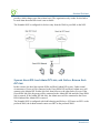
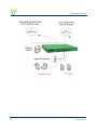
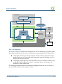
Network Architecture (Sample) .............................................................................................. 25
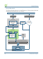
Load Balancing and Link Failover (8.2)..........................................................................
Definitions and Concepts .................................................................................................
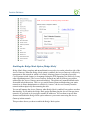
Load Balancing across Multiple Low Speed Links ..........................................................
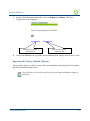
Failover to Standby ISP Link ...........................................................................................
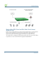
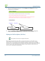
Separate Guest HSIA and Admin ISP Links, with Failover Between Each ISP Link ......
Guest HSIA Failover Only, to Admin Network ................................................................
Sharing of Guest HSIA Network and Hotel Admin Network Amongst
Multiple ISP Links............................................................................................................
Load Balancing With Users Connected to a Preferred ISP Link.....................................
vi
26
26
29
29
30
31
32
33
ACCESS GATEWAY
Online Help (WebHelp) .......................................................................................................... 35
Notes, Cautions, and Warnings............................................................................................... 35
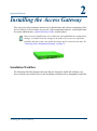
Chapter 2: Installing the Access Gateway ................................................................... 37
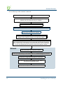
Installation Workflow .............................................................................................................
Powering Up the System.........................................................................................................
User Manual and Documentation ...........................................................................................
Accessory Box Contents...................................................................................................
Start Here ................................................................................................................................
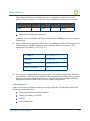
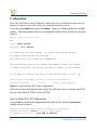
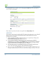
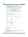
Configuration ..........................................................................................................................
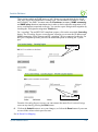
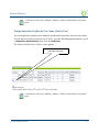
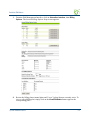
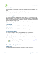
Step 1a: Static WAN IP Configuration ............................................................................
Step 1b: DHCP Client Configuration ..............................................................................
Step 1c: PPPoE Dynamic IP Client Configuration .........................................................
Step 1d: PPPoE Static IP Client Configuration ..............................................................
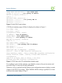
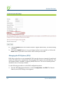
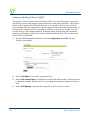
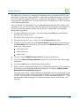
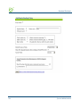
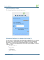
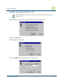
Step 2: Entering Your Location Information ..................................................................
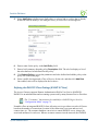
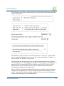
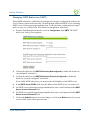
Step 3: Retrieving Your License Key ..............................................................................
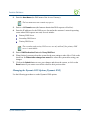
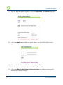
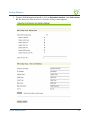
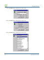
Step 4: Configuring the System.......................................................................................
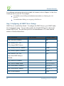
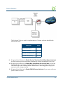
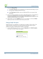
Step 5: Configuring AG DHCP Server Settings ..............................................................
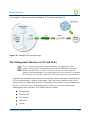
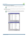
The Management Interfaces (CLI and Web) ..........................................................................
Making Menu Selections and Inputting Data with the CLI .............................................
Menu Organization (Web Management Interface) ..........................................................
Inputting Data – Maximum Character Lengths...............................................................
Online Documentation and Help .....................................................................................
Quick Reference Guide...........................................................................................................
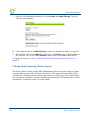
Establishing the Start Up Configuration .................................................................................
Assigning Login User Names and Passwords .................................................................
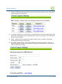
Setting the SNMP Parameters (optional) ........................................................................
37
39
39
40
40
42
42
44
45
46
46
47
47
48
49
50
50
52
53
53
54
55
56
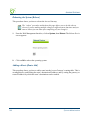
Configuring the WAN interface (8.2)...............................................................................
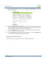
Enabling the Logging Options (recommended)...............................................................
Assigning the Location Information and IP Addresses ...................................................
Logging Out and Powering Down the System........................................................................
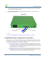
Connecting the Access Gateway to the Customer’s Network ................................................
Establishing the Basic Configuration for Subscribers ............................................................
Setting the DHCP Options ...............................................................................................
DHCP Options from RFC 2132.......................................................................................
Setting the DNS Options ..................................................................................................
Archiving Your Configuration Settings..................................................................................
Installing the Nomadix Private MIB.......................................................................................
57
58
61
63
63
64
65
66
69
70
71
Chapter 3: System Administration............................................................................... 73
Choosing a Remote Connection.............................................................................................. 73
Using the Web Management Interface (WMI) ................................................................. 74
vii
ACCESS GATEWAY
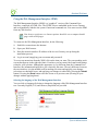
Using an SNMP Manager ................................................................................................ 75
Using a Telnet Client........................................................................................................ 75
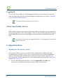
Logging In ............................................................................................................................... 76
About Your Product License ................................................................................................... 76
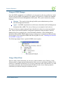
Configuration Menu ................................................................................................................ 76
Defining the AAA Services {AAA}.................................................................................... 76
Establishing Secure Administration {Access Control} .................................................... 87
Defining Automatic Configuration Settings {Auto Configuration}.................................. 90
Setting Up Bandwidth Management {Bandwidth Management} ..................................... 93
Group Bandwidth Limit Policy ........................................................................................ 95
Group Bandwidth Limit Policy – Operation .................................................................... 95
Group Bandwidth Limit Policy – Enable ......................................................................... 96
Group Bandwidth Limit Policy – Current Table.............................................................. 97
Establishing Billing Records “Mirroring” {Bill Record Mirroring} .............................. 98
Configuring Destination HTTP Redirect ....................................................................... 100
Managing the DHCP service options {DHCP} ............................................................. 103
Enabling DNSSEC Support ............................................................................................ 107
Managing the DNS Options {DNS}................................................................................ 108
Managing the Dynamic DNS Options {Dynamic DNS}................................................. 109
viii
Ethernet Ports/WAN (8.2) ..............................................................................................
Setting the Home Page Redirection Options {Home Page Redirect} ............................
Enabling Intelligent Address Translation (iNAT™) ......................................................
Defining IPSec Tunnel Settings {IPSec} ........................................................................
111
113
114
116
Load Balancing (8.2)......................................................................................................
Establishing Your Location {Location} .........................................................................
Managing the Log Options {Logging} ...........................................................................
Enabling MAC Authentication {MAC Authentication} ..................................................
Assigning Passthrough Addresses (Passthrough Addresses).........................................
Assigning a PMS Service {PMS}....................................................................................
Setting Up Port Locations {Port-Location} ...................................................................
Setting up Quality of Service {QoS}...............................................................................
Defining the RADIUS Client Settings {RADIUS Client}................................................
122
124
128
133
134
135
142
148
149
Defining the RADIUS Proxy Settings {RADIUS Proxy} (8.2) .......................................
Defining the Realm-Based Routing Settings {Realm-Based Routing} ...........................
Managing SMTP Redirection {SMTP}...........................................................................
Managing the SNMP Communities {SNMP} .................................................................
Enabling Dynamic Multiple Subnet Support (Subnets)..................................................
Displaying Your Configuration Settings {Summary} .....................................................
Setting the System Date and Time {Time}......................................................................
Setting up Traffic Descriptors ........................................................................................
Setting Up URL Filtering {URL Filtering} ....................................................................
Selecting User Agent Filtering Settings .........................................................................
154
158
167
168
169
171
172
174
175
176
ACCESS GATEWAY
Zone Migration ..............................................................................................................
Defining IPSec Tunnel Settings .....................................................................................
Network Info Menu...............................................................................................................
Displaying ARP Table Entries {ARP} ...........................................................................
Displaying DAT Sessions {DAT} ...................................................................................
Displaying the Host Table {Hosts} ................................................................................
Displaying ICMP Statistics {ICMP}..............................................................................
Displaying the Network Interfaces {Interfaces} ............................................................
177
179
181
181
181
182
183
183
Interface Monitoring (8.2) .............................................................................................
Displaying the IP Statistics {IP}....................................................................................
Viewing IPSec Tunnel Status {IPSec}............................................................................
Viewing NAT IP Address Usage {NAT IP Usage}.........................................................
Displaying the Routing Tables {Routing}......................................................................
185
186
187
187
188
Displaying the Routing Tables {Routing} (8.2) .............................................................
Displaying the Active IP Connections {Sockets} ...........................................................
Displaying the Static Port Mapping Table {Static Port-Mapping} ...............................
Displaying TCP Statistics {TCP}...................................................................................
Displaying UDP Statistics {UDP}.................................................................................
Port-Location Menu ..............................................................................................................
Adding and Updating Port-Location Assignments {Add} .............................................
Deleting All Port-Location Assignments {Delete All} ...................................................
Deleting Port-Location Assignments by Location {Delete by Location} ......................
Deleting Port-Location Assignments by Port {Delete by Port}.....................................
Exporting Port-Location Assignments {Export}............................................................
Finding Port-Location Assignments by Description {Find by Description} .................
Finding Port-Location Assignments by Location {Find by Location} ..........................
Finding Port-Location Assignments by Port {Find by Port}.........................................
Importing Port-Location Assignments {Import}............................................................
Displaying the Port-Location Mappings {List} .............................................................
Subscriber Administration Menu ..........................................................................................
Adding Subscriber Profiles {Add} .................................................................................
Displaying Current Subscriber Connections {Current} ................................................
Deleting Subscriber Profiles by MAC Address {Delete by MAC}.................................
Deleting Subscriber Profiles by User Name {Delete by User}......................................
Displaying the Currently Allocated DHCP Leases {DHCP Leases} ............................
Deleting All Expired Subscriber Profiles {Expired} .....................................................
Finding Subscriber Profiles by MAC Address {Find by MAC}.....................................
Finding Subscriber Profiles by User Name {Find by User}..........................................
Listing Subscriber Profiles by MAC Address {List by MAC}........................................
Listing Subscriber Profiles by User Name {List by User}.............................................
Viewing RADIUS Proxy Accounting Logs {RADIUS Session History}.........................
Displaying Current Profiles and Connections {Statistics} ............................................
189
190
191
192
193
193
194
197
198
199
199
200
201
202
203
205
205
205
211
212
213
214
214
215
215
216
217
218
219
ix
ACCESS GATEWAY
Subscriber Interface Menu .................................................................................................... 219
Defining the Billing Options {Billing Options}.............................................................. 219
Setting Up the Information and Control Console {ICC Setup}...................................... 226
Defining Languages {Language Support} ..................................................................... 233
Enable Serving of Local Web Pages {Local Web Server} ............................................. 236
Defining the Subscriber’s Login UI {Login UI} ............................................................ 237
Defining the Post Session User Interface (Post Session UI).......................................... 241
Defining Subscriber UI Buttons {Subscriber Buttons} .................................................. 244
Defining Subscriber UI Labels {Subscriber Labels} ..................................................... 245
Defining Subscriber Error Messages {Subscriber Errors}............................................ 247
Defining Subscriber Messages {Subscriber Messages} ................................................. 249
System Menu ......................................................................................................................... 252
Adding an ARP Table Entry {ARP Add} ........................................................................ 252
Deleting an ARP Table Entry {ARP Delete}.................................................................. 253
Adding and Deleting ARP Table Entries (8.2) ...............................................................
Configurable Gateway ARP Refresh Interval ................................................................
Enabling the Bridge Mode Option {Bridge Mode} ........................................................
Exporting Configuration Settings to the Archive File {Export}.....................................
Importing the Factory Defaults {Factory} .....................................................................
Defining the Fail Over Options {Fail Over}..................................................................
Viewing the History Log {History} ................................................................................
Establishing ICMP Blocking Parameters {ICMP} ........................................................
Importing Configuration Settings from the Archive File {Import} ................................
Establishing Login Access Levels {Login} .....................................................................
Defining the MAC Filtering Options {Mac Filtering} ...................................................
Utilizing Packet Capturing {Packet Capture} ...............................................................
Rebooting the System {Reboot} ......................................................................................
Adding a Route {Route Add} ..........................................................................................
Deleting a Route {Route Delete}....................................................................................
Establishing Session Rate Limiting {Session Limit} ......................................................
Adding Static Ports {Static Port-Mapping Add} ............................................................
Deleting Static Ports {Static Port-Mapping Delete}......................................................
Blocking a Subscriber Interface {Subscriber Interfaces} ..............................................
Updating the Access Gateway Firmware {Upgrade} ....................................................
253
254
255
256
257
258
259
260
261
262
265
266
268
268
269
270
271
273
274
274
Chapter 4: The Subscriber Interface.......................................................................... 275
Overview ............................................................................................................................... 275
Authorization and Billing ...................................................................................................... 276
The AAA Structure.......................................................................................................... 277
Process Flow (AAA) ....................................................................................................... 280
Internal and External Web Servers ................................................................................ 281
Language Support .......................................................................................................... 281
Home Page Redirection ................................................................................................. 281
x
ACCESS GATEWAY
Subscriber Management........................................................................................................
Subscriber Management Models ...................................................................................
Configuring the Subscriber Management Models .........................................................
Information and Control Console (ICC) ...............................................................................
ICC Pop-Up Window .....................................................................................................
Logout Console ..............................................................................................................
282
282
283
284
284
285
Chapter 5: Quick Reference Guide ............................................................................ 287
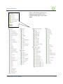
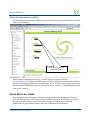
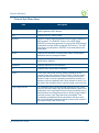
Web Management Interface (WMI) Menus..........................................................................
Configuration Menu Items .............................................................................................
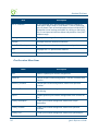
Network Info Menu Items...............................................................................................
Port-Location Menu Items .............................................................................................
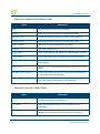
Subscriber Administration Menu Items .........................................................................
Subscriber Interface Menu Items ...................................................................................
System Menu Items.........................................................................................................
Alphabetical Listing of Menu Items (WMI) .........................................................................
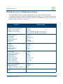
Default (Factory) Configuration Settings .............................................................................
Product Specifications...........................................................................................................
Sample AAA Log..................................................................................................................
Message Definitions (AAA Log) ....................................................................................
Sample SYSLOG Report ......................................................................................................
Sample History Log ..............................................................................................................
Keyboard Shortcuts...............................................................................................................
HyperTerminal Settings ........................................................................................................
RADIUS Attributes...............................................................................................................
Authentication-Request ..................................................................................................
Authentication-Reply (Accept) .......................................................................................
Accounting-Request .......................................................................................................
Selected Detailed Descriptions......................................................................................
Nomadix Vendor Specific Attributes..............................................................................
Setting Up the SSL Feature...................................................................................................
Prerequisites ..................................................................................................................
Obtain a Private Key File (cakey.pem) .........................................................................
Installing Cygwin and OpenSSL on a PC ......................................................................
Private Key Generation .................................................................................................
Create a Certificate Signing Request (CSR) File ..........................................................
Create a Public Key File (server.pem) ..........................................................................
Setting Up Access Gateway for SSL Secure Login ........................................................
Setting Up the Portal Page ............................................................................................
Mirroring Billing Records.....................................................................................................
Sending Billing Records.................................................................................................
XML Interface ................................................................................................................
287
288
291
292
294
294
295
299
301
303
320
320
321
322
323
323
324
325
325
326
327
328
330
330
330
331
334
337
338
341
342
343
343
344
xi
ACCESS GATEWAY
Chapter 6: Troubleshooting ........................................................................................ 347
General Hints and Tips.......................................................................................................... 347
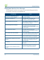
Management Interface Error Messages ................................................................................. 348
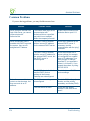
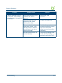
Common Problems ................................................................................................................ 350
Contact Information............................................................................................................... 353
xii
ACCESS GATEWAY
1
Introduction
About this Guide
This User Guide provides information and procedures that will enable system administrators to
install, configure, manage, and use the Access Gateway product successfully and efficiently.
Use this guide to take full advantage of the Access Gateway’s functionality and features.
Refer to “Product Specifications” on page 303 for a list of Access Gateway Products that this
document supports.
The Nomadix Access Gateway hardware is configured and controlled by Nomadix Service
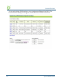
Engine (NSE) software. The NSE 7.4 Release supports the AG2300, AG3100, and AG5500.
NSE 8.0 supports the AG5600 and AG5800.
NSE 8.2 supports the AG2400, AG5600, and AG5800. The NSE 8.2 software provides several
new features, including independent multi-WAN configuration and an optional Load Balancing
module. Features and enhancements specific to NSE 8.2 are labeled (8.2).
Introduction
1
ACCESS GATEWAY
Organization
This User Guide is organized into the following sections:
Chapter 1 – Introduction. The current chapter; an introduction to the features and benefits of
the Nomadix Access Gateway.
Chapter 2 – Installing the Access Gateway. Provides instructions for installing the Access
Gateway and establishing the start-up configuration.
Chapter 3– System Administration. Provides all the instructions and procedures necessary to
manage and administer the Access Gateway on the customer’s network, following a successful
installation.
Chapter 4– The Subscriber Interface. Provides an overview and sample scenario for the
Access Gateway’s subscriber interface. It also includes an outline of the authorization and
billing processes utilized by the system, and the Nomadix Information and Control Console.
Chapter 5 – Quick Reference Guide. Contains product reference information, organized by
topic and functionality. It also contains a full listing of all product configuration elements,
sorted alphabetically and by menu.
Chapter 6 – Troubleshooting. Provides information to help you resolve common hardware and
software problems. It also contains a list of error messages associated with the management
interface.
Appendix A: Technical Support. Informs you how to obtain technical support. Refer to
Troubleshooting before contacting Nomadix, Inc. directly.
Glossary of Terms. Provides an explanation of terms directly related to Nomadix product
technology. Glossary entries are organized alphabetically.
Index. The index is a valuable information search tool. Use the index to locate specific topics
and categories contained in this User Guide.
2
Introduction
ACCESS GATEWAY
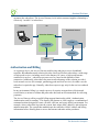
Welcome to the Access Gateway
The Access Gateway is a freestanding, fully featured network appliance that enables public
access service providers to offer broadband Internet connectivity to their customers.
The Access Gateway handles transparent connectivity, advanced security, policy-based traffic
shaping, and service placement supporting thousands of users simultaneously in a broadband
environment. The Access Gateway also offers a unique set of security and connectivity
features for deploying metro wireless 802.11 networks, including Mesh and WiMAX
technologies.
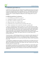
Access Gateway
The Access Gateway yields a complete solution to a set of complex issues in the Enterprise,
Public-LAN, and Residential segments.
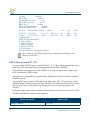
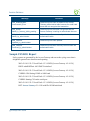
Product Configuration and Licensing
All Nomadix Access Gateway products are powered by our patented and patent-pending suite
of embedded software, called the Nomadix Service Engine™ (NSE). The Access Gateway
employs our NSE core software package and comes pre-packaged with the option to purchase
additional modules to expand the product’s functionality.
This User Guide covers all features and functionality provided with the NSE core package, as
well as additional optional modules. Your product license must support the optional NSE
modules if you want to take advantage of the expanded functionality. The following note will
preface procedures that directly relate to optional modules.
See also:
NSE Core Functionality
Optional NSE Modules
Introduction
3
ACCESS GATEWAY
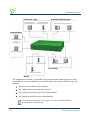
Key Features and Benefits
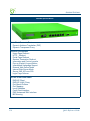
The Access Gateway is a 1U high, free-standing or rack-mountable Access Gateway that
employs three fast Ethernet ports to interface with the router (one for network side) and the
aggregation equipment (two for subscriber side) within the network. It also incorporates an
RS232 serial port for connecting to a Property Management System (PMS) and for system
management and administration, while maintaining one billing relationship with their chosen
provider.
The Access Gateway enables a wide variety of network deployment options for different venue
types. For example:
Allows for flexible WAN Connectivity (T1/E1, Cable, xDSL, and ISDN).
Supports 802.11a/b/g and hybrid networks utilizing wired Ethernet.
Supports key requirements needed to be compliant with the Wi-Fi ZONE™ program.
Allows you to segment your existing network into public and private sections using
VLANs, then leverage your existing network investment to create new revenue
streams.
Enables you to provide Wi-Fi access as a billable service or as an amenity to augment
the main line of business for your venue.
Contains an advanced XML interface for accepting and processing XML commands,
allowing the implementation of a variety of service plans and offerings.
Offers three user-friendly ways of remote management—through a Web interface,
SNMP MIBs, and Telnet interfaces—allowing for scalable, large public access
deployments.
(8.2) Provides .capabilities for load balancing and fail-over management across
multiple ISPs.
Platform Reliability
The Access Gateway is designed as a network appliance, providing maximum uptime and
reliability unlike competitive offerings that use a server-based platform.
Local Content and Services
The Access Gateway’s Portal Page feature intercepts the user’s browser settings and directs
them to a designated Web site to securely sign up for service or log in if they have a preexisting account.
4
Allows the provider to present their customers with local services or have the user
sign up for service at zero expense.
Introduction
ACCESS GATEWAY
Offers both pre and post authentication redirects of the user’s browser, providing
maximum flexibility in service branding.
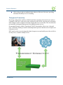
Transparent Connectivity
Resolving configuration conflicts is difficult and time consuming for network users who are
constantly on the move, and costly to the solution provider. In fact, most users are reluctant to
make changes to their computer’s network settings and won’t even bother. This fact alone has
prevented the widespread deployment of broadband network services.
Our patented Dynamic Address Translation™ (DAT) functionality offers a true “plug and
play” solution by enabling a seamless and transparent experience and the tools to acquire new
customers on-site.
DAT greatly reduces provisioning and technical support costs and enables providers to deliver
an easy to use, customer-friendly service.
Introduction
5
ACCESS GATEWAY
Billing Enablement
The Access Gateway supports billing plans using credit cards, scratch cards, or monthly
subscriptions, or direct billing to a hotel’s Property Management System (PMS) and can base
the billable event on a number of different parameters such as time, volume, IP address type, or
bandwidth.
Access Control and Authentication
The Access Gateway ensures that all traffic to the Internet is blocked until authentication has
been completed, creating an additional level of security in the network. Also, the Access
Gateway allows service providers to create their own unique “walled garden,” enabling users
to access only certain predetermined Web sites before they have been authenticated.
Nomadix simultaneously supports the secure browser-based Universal Access Method (UAM),
IEEE 802.1x, and Smart Clients for companies such as Adjungo Networks, Boingo Wireless,
GRIC and iPass. MAC-based authentication is also available.
Security
The patented iNAT™ (Intelligent Network Address Translation) feature creates an intelligent
mapping of IP Addresses and their associated VPN tunnels—by far the most reliable multisession VPN passthrough to be tested against diverse VPN termination servers from companies
such as Cisco, Checkpoint, Nortel and Microsoft. Nomadix’ iNAT feature allows multiple
tunnels to be established to the same VPN server, creating a seamless connection for all users
on the network.
The Access Gateway provides fine-grain management of DoS (Denial of Service) attacks
through its Session Rate Limiting (SRL) feature, and MAC filtering for improved network
reliability.
5-Step Service Branding
A network enabled with the Nomadix Access Gateway offers a 5-Step service branding
methodology for service providers and their partners, comprising:
6
1.
Initial Flash Page branding.
2.
Initial Portal Page Redirect (Pre-Authentication). Typically, this is used to redirect the user
to a venue-specific Welcome and Login page.
3.
Home Page Redirect (Post-Authentication). This redirect page can be tailored to the
individual user (as part of the RADIUS Reply message, the URL is received by the NSE)
or set to re-display itself at freely configurable intervals.
Introduction
ACCESS GATEWAY
4.
The Information and Control Console (ICC) contains multiple opportunities for an
operator to display its branding or the branding of partners during the user’s session. As an
alternative to the ICC, a simple pop-up window provides the opportunity to display a
single logo.
5.
The “Goodbye” page is a post-session page that can be defined either as a RADIUS VSA
or be driven by the Internal Web Server (IWS) in the NSE. Using the IWS option means
that this functionality is also available for other post-paid billing mechanisms (for
example, post-paid PMS).
Introduction
7
ACCESS GATEWAY
NSE Core Functionality
Powering Nomadix’ family of Access Gateways, the Nomadix Service Engine (NSE) delivers
a full range of features needed to successfully deploy public access networks. These “core”
features solve issues of connectivity, security, billing, and roaming in a Wi-Fi public access
network.
The NSE’s core package of features includes:
8
Access Control
Bandwidth Management
Billing Records Mirroring
Bridge Mode
Command Line Interface
Credit Card
Dynamic Address Translation™
Dynamic Transparent Proxy
End User Licensee Count
External Web Server Mode
Home Page Redirect
iNAT™
Information and Control Console
Internal Web Server
International Language Support
IP Upsell
Logout Pop-Up Window
MAC Filtering
Multi-Level Administration Support
Multi-WAN Interface Management (8.2)
NTP Support
Portal Page Redirect
RADIUS Client
Introduction
ACCESS GATEWAY
RADIUS-driven Auto Configuration
RADIUS Proxy
Realm-Based Routing
Remember Me and RADIUS Re-Authentication
Secure Management
Secure Socket Layer (SSL)
Secure XML API
Session Rate Limiting (SRL)
Session Termination Redirect
Smart Client Support
SNMP Nomadix Private MIB
Static Port Mapping
Tri-Mode Authentication
URL Filtering
Walled Garden
Web Management Interface
Access Control
For IP-based access control, the NSE incorporates a master access control list that checks the
source (IP address) of administrator logins. A login is permitted only if a match is made with
the master list contained within the NSE. If a match is not made, the login is denied, even if a
correct login name and password are supplied.
The access control list supports up to 50 (fifty) entries in the form of a specific IP address or
range of IP addresses.
The NSE also offers access control based on the interface being used. This feature allows
administrators to block access from Telnet, Web Management, and FTP sources.
Administration can now be performed after unblocking the interfaces for the Subscriber side of
the NSE. The Administrative ports are configurable as well. See “Establishing Secure
Administration {Access Control}” on page 87.
Introduction
9
ACCESS GATEWAY
Bandwidth Management
The NSE optimizes bandwidth by limiting bandwidth usage symmetrically or asymmetrically
on a per device (MAC address / User) basis, and manages the WAN Link traffic to provide
complete bandwidth management over the entire network. You can ensure that every user has a
quality experience by placing a bandwidth ceiling on each device accessing the network, so
every user gets a fair share of the available bandwidth.
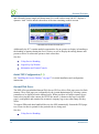
With the Nomadix ICC feature enabled, subscribers can increase or decrease their own
bandwidth and pricing plans for their service dynamically.
Bandwidth selection (pull down)
Information and Control Console (ICC)
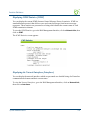
Billing Records Mirroring
NSE-powered devices can send copies of credit card billing records (and optionally, PMS) to
external servers that have been previously defined by system administrators. The NSE assumes
control of billing transmissions and the saving of billing records. By effectively “mirroring”
the billing data, the NSE can send copies of billing records to predefined “carbon copy”
servers. Additionally, if the primary and secondary servers are not responding, the NSE can
store up to 2,000 billing records. The NSE regularly attempts to connect with the primary and
secondary severs. When a connection is re-established (with either server), the NSE sends the
cached information to the server. Customers can be confident that their billing information is
secure and that no transaction records are lost.
Bridge Mode
This feature allows complete and unconditional access to devices. When Bridge Mode is
enabled, your NSE-powered product is effectively transparent to the network in which it is
located.
10
Introduction
ACCESS GATEWAY
The NSE forwards any and all packets (except those addressed to the NSE network interface).
The packets are unmodified and can be forwarded in both directions. The Bridge Mode
function is a very useful feature when troubleshooting your entire network as it allows
administrators to effectively “remove” your product from the network without physically
disconnecting the unit.
Command Line Interface
The Command Line Interface (CLI) is a character-based user interface that can be accessed
remotely or via a direct cable connection. Until your Nomadix product is up and running on the
network, the CLI is the Network Administrator’s window to the system. Software upgrades
can only be performed from the CLI.
See also “The Management Interfaces (CLI and Web)” on page 49.
Credit Card
The Credit Card provides a secure interface over SSL to enable billing via a credit card for
High Speed Internet Access (HSIA). This module also includes the Bill Mirror functionality
for posting of billing records to multiple sources.
See also:
“Secure Socket Layer (SSL)” on page 20.
“Billing Records Mirroring” on page 10.
Dynamic Address Translation™
Dynamic Address Translation (DAT) enables transparent broadband network connectivity,
covering all types of IP configurations (static IP, DHCP, DNS), regardless of the platform or
the operating system used—ensuring that everyone gets access to the network without the need
for changes to their computer’s configuration settings or client-side software. The NSE
supports both PPTP and IPSec VPNs in a manner that is transparent to the user and that
provides a more secure standard connection. See also, “Transparent Connectivity” on page 5.
Dynamic Transparent Proxy
The NSE directs all HTTP and HTTPS proxy requests through an internal proxy which is
transparent to subscribers (no need for users to perform any reconfiguration tasks). Uniquely,
the NSE also supports clients that dynamically change their browser status from non-proxy to
proxy, or vice versa. In addition, the NSE supports proxy ports 80, 800-900, 911 and 990 as
well as all unassigned ports (for example, ports above 1024), thus ensuring far fewer proxy
related support calls than competitive products.
Introduction
11
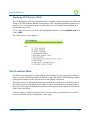
ACCESS GATEWAY
End User Licensee Count
The NSE supports a range of simultaneous user counts depending on the Nomadix Access
Gateway you choose. In addition, depending on your platform, various user count upgrades are
available for each of our NSE-powered products that allow you to increase the simultaneous
user count.
External Web Server Mode
The External Web Server (EWS) interface is for customers who want to develop and use their
own content. It allows you to create a “richer” environment than is possible with your product’s
embedded Internal Web Server.
The advantages of using an External Web Server are:
Manage frequently changing content from one location.
Serve different pages depending on site, sub-location (for example, VLAN), and user.
Take advantage of the comprehensive Nomadix XML API to implement more
complex billing plans.
Recycle existing Web page content for the centrally hosted portal page.
If you choose to use the EWS interface, Nomadix Technical Support can provide you with
sample scripts. See also, “Contact Information” on page 353.
Home Page Redirect
The NSE supports a comprehensive HTTP redirect logic that allows network administrators to
define multiple instances to intercept the browser’s request and replace it with freely
configurable URLs.
Portal page redirect enables redirection to a portal page before the authentication process. This
means that anyone will get redirected to a Web page to establish an account, select a service
plan, and pay for access. Home Page redirect enables redirection to a page after the
authentication process (for example, to welcome a specific user to the service—after the user
has been identified by the authentication process. See also, “Portal Page Redirect” on page 17.
iNAT™
Nomadix invented a new way of intelligently supporting multiple VPN connections to the
same termination at the same time (iNAT™), thus solving a key problem of many public access
networks.
12
Introduction
ACCESS GATEWAY
Nomadix’ patented iNAT™ (intelligent Network Address Translation) feature contains an
advanced, real-time translation engine that analyzes all data packets being communicated
between the private address realm and the public address realm.
The NSE performs a defined mode of network address translation based on packet type and
protocol (for example, ISAKMP, etc.). UDP packet fragmentation is supported to provide more
seamless translation engine for certificate-based VPN connections.
If address translation is needed to ensure the success of a specific application (for example,
multiple users trying to access the same VPN termination server at the same time), the packet
engine selects an IP address from a freely definable pool of publicly routable IP addresses. The
same public IP address can be used as a source IP to support concurrent tunnels to different
termination devices—offering unmatched efficiency in the utilization of costly public IP
addresses. If the protocol type can be supported without the use of a public IP (for example,
HTTP, FTP), our proven Dynamic Address Translation™ functionality continues to be used.
Some of the benefits of iNAT™ include:
Improves the success rate of VPN connectivity by misconfigured users, thus reducing
customer support costs and boosting customer satisfaction.
Maintains the security benefits of traditional address translation technologies while
enabling secure VPN connections for mobile workers accessing corporate resources
from a public access location.
Dynamically adjusts the mode of address translation during the user's session,
depending on the packet type.
Supports users with static private IP addresses (for example, 192.168.x.x) or public
(different subnet) IP addresses without any changes to the client IP settings.
Dramatically heightens the reusability factor of costly public IP addresses.
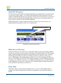
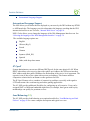
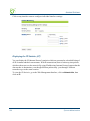
Information and Control Console
The Nomadix ICC is a HTML-based pop-up window that is presented to subscribers with their
Web browser. The ICC allows subscribers to select their bandwidth and billing options quickly
Introduction
13
ACCESS GATEWAY
and efficiently from a simple pull-down menu. For credit card accounts, the ICC displays a
dynamic “time” field to inform subscribers of the time remaining on their account.
Information and Control Console (ICC)
Additionally, the ICC contains multiple opportunities for an operator to display its branding or
the branding of partners during the user’s session, as well as display advertising banners and
present a choice of redirection options to their subscribers.
See also:
5-Step Service Branding
Logout Pop-Up Window
Information and Control Console
Initial NSE Configuration (8.2)
See “Installing the Access Gateway” on page 37 for initial installation and configuration
instructions.
Internal Web Server
The NSE offers an embedded Internal Web Server (IWS) to deliver Web pages stored in flash
memory. These Web pages are configurable by the system administrator by selecting various
parameters to be displayed on the internal pages. When providers or HotSpot owners do not
want to develop their own content, the IWS is the answer. A banner at the top of each IWS
page is configurable and contains the customer's company logo or any other image file they
desire.
To support PDAs and other hand-held devices, the NSE automatically formats the IWS pages
to a screen size that is optimal for the particular device being used.
See also:
14
5-Step Service Branding.
Introduction
ACCESS GATEWAY
International Language Support.
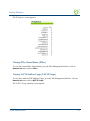
International Language Support
The NSE allows you to define the text displayed to your users by the IWS without any HTML
or ASP knowledge. The language you select determines the language encoding that the IWS
instructs the browser to use. See also, “Internal Web Server” on page 14.
NSE 8.2 also allows you to change the language of the Web Management Interface text. See
“Selecting the language of the Web Management Interface” on page 74.
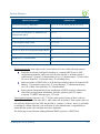
The available language options are:
English
Chinese (Big 5)
French
German
Japanese (Shift_JIS)
Spanish
Other, with drop-down menu
IP Upsell
System administrators can set two different DHCP pools for the same physical LAN. When
DHCP subscribers select a service plan with a public pool address, the NSE associates their
MAC address with their public IP address for the duration of the service level agreement. The
opposite is true if they select a plan with a private pool address. This feature enables a
competitive solution and is an instant revenue generator for ISPs.
The IP Upsell feature solves a number of connectivity problems, especially with regard to
L2TP and certain video conferencing and online gaming applications.
The 8.2 NSE provides additional flexibility for configuring up sell scenarios. Users can be
assigned WAN’s of different bandwidth capabilities; for example, hotel guests with loyalty
memberships can qualify for premium services.
Load Balancing (8.2)
The 8.2 NSE provides load balancing as an optional module See “Load Balancing and Link
Failover” on page 26 for a more complete description and typical use cases.
Introduction
15
ACCESS GATEWAY
Logout Pop-Up Window
As an alternative to the ICC, the NSE delivers a HTML-based pop-up window with the
following functions:
Provides the opportunity to display a single logo.
Displays the session’s elapsed/count-down time.
Presents an explicit Logout button.
See also, “Information and Control Console” on page 13.
MAC Filtering
MAC Filtering enhances Nomadix' access control technology by allowing system
administrators to block malicious users based on their MAC address. Up to 50 MAC addresses
can be blocked at any one time. See also, “Session Rate Limiting (SRL)” on page 20.
Multi-Level Administration Support
The NSE allows you to define 2 concurrent access levels to differentiate between managers and
operators, where managers are permitted read/write access and operators are restricted to read
access only.
Once the logins have been assigned, managers have the ability to perform all write commands
(Submit, Reset, Reboot, Add, Delete, etc.), but operators cannot change any system settings.
When Administration Concurrency is enabled, one manager and three operators can access the
Access Gateway platform at any one time.
Multi-WAN Interface Management (8.2)
The 8.2 NSE supports multiple independently configurable WAN interfaces, to optimize ISP
resource allocation, and provide load balancing (optional), fail-over and upsell capabilities.
NTP Support
The NSE supports Network Time Protocol (NTP), an Internet standard protocol that assures
accurate synchronization (to the millisecond) of computer clock times in a network of
computers. NTP synchronizes the client’s clock to the U.S. Naval Observatory master clocks.
Running as a continuous background client program on a computer, NTP sends periodic time
requests to servers, obtaining server time stamps and using them to adjust the client's clock.
16
Introduction
ACCESS GATEWAY
Portal Page Redirect
The NSE contains a comprehensive HTTP page redirection logic that allows for a page redirect
before (Portal Page Redirect) and/or after the authentication process (Home Page Redirect).
As part of the Portal Page Redirect feature, the NSE can send a defined set of parameters to the
portal page redirection logic that allows an External Web Server to perform a redirection based
on:
Access Gateway ID and IP Address
Origin Server
Port Location
Subscriber MAC address
Externally hosted RADIUS login failure page
This means that the network administrator can now perform location-specific service branding
(for example, an airport lounge) from a centralized Web server.
See also, “Home Page Redirect” on page 12.
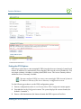
RADIUS-driven Auto Configuration
Nomadix’ unique RADIUS-driven Auto Configuration functionality utilizes the existing
infrastructure of a mobile operator to provide an effortless and rapid method for configuring
devices for fast network roll-outs. Once configured, this methodology can also be effectively
used to centrally manage configuration profiles for all Nomadix devices in the public access
network.
Two subsequent events drive the automatic configuration of Nomadix devices:
1.
A flow of RADIUS Authentication Request and Reply messages between the Nomadix
gateway and the centralized RADIUS server that specifies the location of the meta
configuration file (containing a listing of the individual configuration files and their
download frequency status) are downloaded from an FTP server into the flash of the
Nomadix device.
2.
Defines the automated login into the centralized FTP server and the actual download
process into the flash.
Optionally, the RADIUS authentication process and FTP download can be secured by sending
the traffic through a peer-to-peer IPSec tunnel established by the Nomadix gateway and
terminated at the NOC (Network Operations Center). See also, “Secure Management” on
page 19.
Introduction
17
ACCESS GATEWAY
(8.2) The 8.2 NSE provides a Radius VSA that supports assigning specific users to specific
WAN interface. See “Defining Automatic Configuration Settings {Auto Configuration}” on
page 90.
RADIUS Client
Nomadix offers an integrated RADIUS (Remote Authentication Dial-In User Service) client
with the NSE allowing service providers to track or bill users based on the number of
connections, location of the connection, bytes sent and received, connect time, etc. The
customer database can exist in a central RADIUS server, along with associated attributes for
each user. When a customer connects into the network, the RADIUS client authenticates the
customer with the RADIUS server, applies associated attributes stored in that customer's
profile, and logs their activity (including bytes transferred, connect time, etc.). The NSE's
RADIUS implementation also handles vendor specific attributes (VSAs), required by WISPs
that want to enable more advanced services and billing schemes, such as a per device/per
month connectivity fee. See also, “RADIUS Proxy” on page 18.
RADIUS Proxy
The RADIUS Proxy feature relays authentication and accounting packets between the parties
performing the authentication process. Different realms can be set up to directly channel
RADIUS messages to the various RADIUS servers. This functionality can be effectively
deployed to:
Support a wholesale WISP model directly from the edge without the need for any
centralized AAA proxy infrastructure.
Support EAP authenticators (for example, WLAN APs) on the subscriber-side of the
NSE to transparently proxy all EAP types (TLS, SIM, etc.) and to allow for the
distribution of per-session keys to EAP authenticators and supplicants.
Complementing the RADIUS Proxy functionality is the ability to route RADIUS messages
depending on the Network Access Identifier (NAI). Both prefix-based (for example, ISP/
[email protected]) and suffix-based ([email protected]) NAI routing mechanisms are
supported. Together, the RADIUS Proxy and Realm-Based Routing further support the
deployment of the Wholesale Wi-Fi™ model allowing multiple providers to service one
location. See also, “RADIUS Client” on page 18.
Realm-Based Routing
Realm-Based Routing provides advanced NAI (Network Access Identifier) routing
capabilities, enabling multiple service providers to share a HotSpot location, further supporting
a Wi-Fi wholesale model. This functionality allows users to interact only with their chosen
provider in a seamless and transparent manner.
18
Introduction
ACCESS GATEWAY
Remember Me and RADIUS Re-Authentication
The NSE’s Internal Web Server (IWS) stores encrypted login cookies in the browser to
remember logins, using usernames and passwords. This “Remember Me” functionality creates
a more efficient and better user experience in wireless networks.
The RADIUS Re-Authentication buffer has been expanded to 720 hours, allowing an even
more seamless and transparent connection experience for repeat users.
Secure Management
There are many different ways to configure, manage and monitor the performance and up-time
of network devices. SNMP, Telnet, HTTP and ICMP are all common protocols to accomplish
network management objectives. And within those objectives is the requirement to provide the
highest level of security possible.
While several network protocols have evolved that offer some level of security and data
encryption, the preferred method for attaining maximum security across all network devices is
to establish an IPSec tunnel between the NOC (Network Operations Center) and the edge
device (early VPN protocols such as PPTP have been widely discredited as a secure tunneling
method).
As part of Nomadix’ commitment to provide outstanding carrier-class network management
capabilities to its family of public access gateways, we offer secure management through the
NSE’s standards-driven, peer-to-peer IPSec tunneling with strong data encryption.
Establishing the IPSec tunnel not only allows for the secure management of the Nomadix
gateway using any preferred management protocol, but also the secure management of third
party devices (for example, WLAN Access Points and 802.3 switches) on private subnets on
the subscriber side of the Nomadix gateway. See also, “Defining IPSec Tunnel Settings” on
page 179.
Two subsequent events drive the secure management function of the Nomadix gateway and the
devices behind it:
1.
Establishing an IPSec tunnel to a centralized IPSec termination server (for example,
Nortel Contivity). As part of the session establishment process, key tunnel parameters are
exchanged (for example, Hash Algorithm, Security Association Lifetimes, etc.).
2.
The exchange of management traffic, either originating at the NOC or from the edge
device through the IPSec tunnel. Alternatively, AAA data such as RADIUS
Authentication and Accounting traffic can be sent through the IPSec tunnel. See also,
“RADIUS-driven Auto Configuration” on page 17.
The advantage of using IPSec is that all types of management traffic are supported, including
the following typical examples:
Introduction
ICMP - PING from NOC to edge devices
19
ACCESS GATEWAY
Telnet - Telnet from NOC to edge devices
Web Management - HTTP access from NOC to edge devices
SNMP
SNMP GET from NOC to subscriber-side device (for example, AP)
SNMP SET from NOC to subscriber-side device (for example, AP)
SNMP Trap from subscriber-side device (for example, AP) to NOC
Secure Socket Layer (SSL)
This feature allows for the creation of an end-to-end encrypted link between your NSEpowered product and wireless clients by enabling the Internal Web Server (IWS) to display
pages under a secure link—important when transmitting AAA information in a wireless
network when using RADIUS.
SSL requires service providers to obtain digital certificates to create HTTPS pages.
Instructions for obtaining certificates are provided by Nomadix.
Secure XML API
XML (Extensible Markup Language) is used by the subscriber management module for user
administration. The XML interface allows the NSE to accept and process XML commands
from an external source. XML commands are sent over the network to your NSE-powered
product which executes the commands, and returns data to the system that initiated the
command request. XML enables solution providers to customize and enhance their product
installations.
This feature allows the operator to use Nomadix' popular XML API using the built-in SSL
certificate functionality in the NSE so that parameters passed between the Gateway and the
centralized Web server are secured via SSL.
If you plan to implement XML for external billing, please contact technical
support for the XML specification of your product. Refer to “Contact
Information” on page 353.
Session Rate Limiting (SRL)
Session Rate Limiting (SRL) significantly reduces the risk of “Denial of Service” attacks by
allowing administrators to limit the number sessions any one user can take over a given time
period and, if necessary, then block malicious users.
20
Introduction
ACCESS GATEWAY
Session Termination Redirect
Once connected to the public access network, the NSE will automatically redirect the customer
to a Web site for local or personalized services if the customer logs out or the customer’s
account expires while online and the goodbye page is enabled. In addition, the NSE also
provides pre- and post-authentication redirects as well as one at session termination.
Smart Client Support
The NSE supports authentication mechanisms used by Smart Clients by companies such as
Adjungo Networks, Boingo Wireless, GRIC and iPass.
SNMP Nomadix Private MIB
Nomadix’ Access Gateways can be easily managed over the Internet with an SNMP client
manager (for example, HP OpenView or Castle Rock).
To take advantage of the functionality provided with Nomadix’ private MIB (Management
Information Base), simply import the nomadix.mib file from the Accessories CD (supplied
with the product) to view and manage SNMP objects on your product.
See also:
Using an SNMP Manager
Installing the Nomadix Private MIB
Static Port Mapping
This feature allows the network administrator to setup a port mapping scheme that forwards
packets received on a specific port to a particular static IP (typically private and
misconfigured) and port number on the subscriber side of the NSE. The advantage for the
network administrator is that free private IP addresses can be used to manage devices (such as
Access Points) on the subscriber side of the NSE without setting them up with Public IP
addresses.
Tri-Mode Authentication
The NSE enables multiple authentication models providing the maximum amount of flexibility
to the end user and to the operator by supporting any type of client entering their network and
any type of business relationship on the back end. For example, in addition to supporting the
secure browser-based Universal Access Method (UAM) via SSL, Nomadix is the only
Introduction
21
ACCESS GATEWAY
company to simultaneously support port-based authentication using IEEE 802.1x and
authentication mechanisms used by Smart Clients. MAC-based authentication is also available.
See also:
Access Control and Authentication
Smart Client Support
URL Filtering
The NSE can restrict access to specified Web sites based on URLs defined by the system
administrator. URL filtering will block access to a list of sites and/or domains entered by the
administrator using the following three methods:
Host IP address (for example, 1.2.3.4).
Host DNS name (for example, www.yahoo.com).
DNS domain name (for example, *.yahoo.com, meaning all sites under the
yahoo.com hierarchy, such as finance.yahoo.com, sports.yahoo.com, etc.).
The system administrator can dynamically add or remove up to 300 specific IP addresses and
domain names to be filtered for each property.
Walled Garden
The NSE provides up to 300 IP passthrough addresses (and/or DNS entries), allowing you to
create a “Walled Garden” within the Internet where unauthenticated users can be granted or
denied access to sites of your choosing.
Web Management Interface
Nomadix’ Access Gateways can be managed remotely via the built-in Web Management
Interface where various levels of administration can be established. See also, “Using the Web
Management Interface (WMI)” on page 74.
22
Introduction
ACCESS GATEWAY
Optional NSE Modules
Load Balancing (8.2)
Load Balancing requires an optional NSE product license
With the 8.2 NSE Load Balancing Module, Internet traffic is balanced across multiple WAN/
ISP connections to ensure that traffic is distributed based on the capability of each connection.
For example, organizations may wish to balance traffic between a low-cost DSL WAN/ISP and
one high-performance, high-capacity WAN/ISP. This is of value when multiple links are used
to optimize cost for Internet service, such as balancing traffic between one low-cost DSL
WAN/ISP and one high-performance, high-capacity WAN/ISP. Hotels may also use this
capability to provide tiered services reflecting the capacity of the WAN/ISP connection.
The Link Failover feature of the Load Balancing Module is designed to improve business
continuity. In the event that one or more links fail, traffic is seamlessly rerouted to the
remaining surviving links without lapse of service. When the failed links recover, the NSE
routes new connections toward the now-working links until a normal, balanced configuration
is reached.
For details of the Load Balancing capabilities and sample use cases, see “Load Balancing and
Link Failover” on page 26.
Hospitality Module
The optional Hospitality Module provides the widest range of Property Management System
(PMS) interfaces to enable in-room guest billing for High Speed Internet Access (HSIA)
service. This module also includes 2-Way PMS interface capability for in-room billing in a WiFi enabled network. In addition, the Hospitality Module includes the Bill Mirror functionality
for posting of billing records to multiple sources. With this module, the NSE also supports
billing over a TCP/IP connection to select PMS interfaces.
Introduction
23
ACCESS GATEWAY
PMS Integration
Your product license may not support this feature.
Some Property Management Systems may require you to obtain a license before
integrating the PMS with the Access Gateway. Check with the PMS vendor.
By integrating with a hotel’s PMS, your NSE-powered product can post charges for Internet
access directly to a guest’s hotel bill. In this case, the guest is billed only once. The NSE
outputs a call accounting record to the PMS system whenever a subscriber purchases Internet
service and decides to post the charges to their room. Nomadix’ Access Gateways are equipped
with a serial PMS interface port to facilitate connectivity with a customer’s Property
Management System.
High Availability Module
Your product license may not support this feature.
The optional High Availability Module offers enhanced network uptime and service
availability when delivering high-quality Wi-Fi service by providing Fail-Over functionality.
This module allows a secondary Nomadix Access Gateway to be placed in the network that can
take over if the primary device fails, ensuring Wi-Fi service remains uninterrupted.
24
Introduction
ACCESS GATEWAY
Network Architecture (Sample)
The Access Gateway can be deployed effectively in a variety of wireless and wired broadband
environments where there are many users—usually mobile—who need high speed access to
the Internet.
The following example shows a potential Hospitality application:
Phone
Laptop
DSL Modem
PMS
DSLAM
PBX
AG
Router
Introduction
25
ACCESS GATEWAY
Load Balancing and Link Failover (8.2)
This section describes the optional NSE 8.2 Load Balancing features. The 8.2 NSE supports
individual configuration of multiple WANs on an Access Gateway (supported on AG2400,
AG5600, and AG5800 hardware). Hotels can use this capability in a number of ways,
including load balancing, failure protection, and subscriber allocation.
This section provides use cases and scenarios to help you consider the full advantage of these
capabilities.
Definitions and Concepts
Load Balancing
Load balancing refers to the general process of balancing user traffic across multiple ISP
connections. All load-balancing appliances, as well as the Nomadix NSE, support load
balancing.
Link Aggregation
Link aggregation refers to the process of connecting multiple ISP connections to an appliance
and having the sum of all of the ISP bandwidth available to be shared across all users.
However, one individual connection is limited to the speed of the ISP connection that is
currently being used. For example, a hotel may aggregate 5 x 1.5Mbps DSL connections
together. This means that a total of 7.5Mbps of bandwidth is available to be shared across all
users, but a single user can receive a maximum of 1.5Mbps. All load-balancing appliances, as
well as the Nomadix NSE, support link aggregation. In most cases, link aggregation and load
balancing is effectively the same thing.
Link Failover
Link failover (sometimes referred to ISP redundancy) is the process of providing a second (or
occasionally a third or more) ISP link as a back up to the primary ISP link. In the event that the
primary link fails, all traffic is re-routed to the backup link, until such time as the primary link
becomes available.
Combined Load Balancing and Link Failover
This is the process where both load balancing and link failover are combined together. It
represents the best of both worlds. Where multiple ISP links are used in load balancing mode,
in the event that one or more links fail, all traffic is automatically rerouted to the remaining
surviving links. When the failed links recover, new connections are routed toward these until
the normal balanced configuration is reached.
26
Introduction
ACCESS GATEWAY
ISP link Selection Criteria
In a load-balancing scenario, some criteria must be used to decide which ISP is selected for
outgoing traffic. There a number of factors that influence this decision, including:
Identity of the users: Is a random ISP section used or is it desirable to have certain
users steered toward a particular ISP?
For random ISP: Whether subscriber, destination address or session-based link
selection is used?
User-Based ISP Selection versus Random ISP Selection
User-based ISP selection is the process whereby the ISP link that is selected in a load-balanced
environment is based on the identity of the user. For example, all users from guest rooms may
be steered toward one ISP link, and all meeting room users steered toward another ISP link that
is only used for meetings and conferences.
The alternative is to use random ISP selection, whereby the load balancer or NSE selects the
ISP to be used according to the current load conditions. The Nomadix NSE uses random ISP
selection by default.
Link Availability Detection Method and Time
Load balancing and failover requires some form of monitoring of each ISP link to determine
its availability for executing load balancing and failover decisions. Generally, link monitoring
is accomplished by two different methods:
1.
Periodic probing of predefined hosts using HTTP or ICMP ping requests.
2.
Periodic DNS queries to the DNS servers provided by each ISP.
The period between successive link tests is usually configured, and is typically set to between
30 seconds and 60 seconds. This represents the maximum time for which a user will remain
connected to a failed ISP connection before being re-routed to a working ISP link in an ISP
failure scenario.
Traffic Balancing and Weighting
Load balancers have some form of weighting of traffic between links to achieve a desired
balance scenario. With the Nomadix NSE, traffic is balanced by individual subscriber
numbers, and weighted according to the speed of the ISP connected to each port. For example,
if an NSE has 2 x 10M links connected and currently has 100 active subscribers, then 50 users
would be connected to each link. If the ISP links were 10 Mbps and 40Mbps, then 20 users
would be connected to the 10M link and 80 users to the 40M link, and so on.
Introduction
27
ACCESS GATEWAY
Load Rebalancing upon Link Recovery
Load balancing and failover with well-configured link availability detection provides fast and
effective recovery from ISP link failure occurrences. Additional consideration must be made as
to what actions should be taken when a failed ISP link recovers. The Nomadix approach is to
rebalance as the ISP links change, thus making sure the maximum level of service is always
provided. There is a small yet important waiting time to ensure changing links is kept to a
minimum.
Load Balancing and Failure Considerations
1.
Is load balancing or just ISP failover required?
2.
Is aggregation of multiple low-speed links required?
3.
How reliable are different local ISP services?
4.
What are the relative costs of different ISP services?
5.
Do ISP links need to be shared between guest and back-office users?
6.
Is there a requirement to have certain users connected to a particular ISP?
1. It may be a requirement to provide just a backup service to the primary ISP service in the
case that the main HSIA ISP fails. The backup service may be on a pay-to-use basis through a
3G or 4G wireless modem, or be a low-cost, lower-tier service, such as a cable modem service,
that is only used when the main ISP link is down, on the basis that providing a reduced HSIA
service is better than no service at all when the main ISP link is down. Alternatively, the
organization may have multiple ISP links, and wants to be able to fully utilize all of them under
normal conditions. The Nomadix NSE supports both failover only and combined load
balancing with failover.
2. In some instances, suitable high-speed internet services required to meet the aggregate needs
of the organization may not be available or are simply too expensive. In this case it may be
desirable to aggregate multiple lower-cost, lower-speed lines together. The Nomadix AG2400
and AG5600 can aggregate services from up to three ISP links, and the AG5800 can handle up
to five links.
3. It is important to consider the relative quality of each ISP link. If a second link is much lower
quality than the main ISP link, then it should only be used as a back-up link in failover mode,
and not in a load-balanced environment. If the quality of the links is much the same, then load
balancing with failover should be used.
4. It is important to consider the relative cost of links. If all links have a fixed monthly charge,
then ideally they should be used in a load-balanced mode, so that costly links are not sitting
unused most of the time. But if an ISP link has a relatively low monthly charge with high permegabyte data usage charges, then it should only be used in failover mode as a backup to a
main ISP link.
28
Introduction
ACCESS GATEWAY
5. It may be requirement to share ISP bandwidth between Guest HSIA and Hotel Admin
networks, or have each network available as a fall-back network for the other. Both scenarios
can be handled with the Nomadix NSE.
6. It may be desirable to have certain users connected to a particular ISP link, and other users
connected to a different ISP link. Nomadix 8.2 NSE provides a "preferred WAN" radius
attribute (VSA). For example, paying users may be connected to an expensive high-quality
link, with free users connected to a lower-quality link, with link failover still available if the
preferred link fails.
Some examples of typical common deployment scenarios are outlined below: These are just
examples and other deployment scenarios can be handled, as well.
Load Balancing across Multiple Low Speed Links
In this example, an establishment has access to only low-speed, DSL-based ISP circuits and
wishes to aggregate five such links together. The Nomadix NSE is configured with load
balancing between all links.
Failover to Standby ISP Link
In this example, the organization has a high-quality 100M Ethernet service. But to guarantee
continuous HSIA service, the organization has a back-up ISP service from a low-cost wireless
Introduction
29
ACCESS GATEWAY
provider, which charges on a data volume basis. The organization only wishes for this link to
be used when the main ISP circuit is not available.
The Nomadix NSE is configured for failover only from the WAN to port Eth2 on the NSE.
Separate Guest HSIA and Admin ISP Links, with Failover Between Each
ISP Link
In this scenario, the hotel has separate HSIA and Hotel Admin ISP circuits. Under normal
circumstances, Guests will be connected to the Guest HSIA ISP, and Hotel Admin users will
connect to the Admin ISP. If either link fails, then failover to the other link will occur. If the
Guest HSIA link fails, the guests will be connected to the Admin ISP link until the Guest HSIA
link is restored. If the Admin ISP link fails, the Admin users will be connected to the Guest
HSIA link until the Admin ISP is restored
The Nomadix NSE is configured with load balancing and failover. All Guests use ISP 1 as the
preferred WAN, the Admin network router uses ISP2 as the preferred WAN.
30
Introduction
ACCESS GATEWAY
Guest HSIA Failover Only, to Admin Network
In this scenario, the hotel has separate ISP circuits for the Guest HSIA network and Hotel
Admin network. The hotel wants the Admin network to be available as a back-up link in case
the Guest HSIA ISP link fails. There is no back-up for the Admin ISP network.
The Nomadix NSE is configured with link failover between the WAN port and port ETH2,
which is connected to the hotel Admin network router.
Introduction
31
ACCESS GATEWAY
Sharing of Guest HSIA Network and Hotel Admin Network Amongst
Multiple ISP Links
In this scenario, multiple ISP links are connected to the Nomadix NSE, in a similar method to
the first scenario, but both the guest HSIA network and the Hotel Admin network are
connected to the NSE and share the aggregate bandwidth of the combined ISP links.
The Nomadix NSE is configured for load balancing, and the back office router's MAC address
is registered in as a device in the NSE with an appropriate bandwidth limit.
32
Introduction
ACCESS GATEWAY
Load Balancing With Users Connected to a Preferred ISP Link
In this scenario the hotel has purchased 2 x ISP links for guest HSIA. One is a high-quality,
high-cost "business grade" ISP circuit, and the other is a low-cost, lower-grade domestic
service provided by the local cable TV operator. The hotel has a number of bill plan options
including free-to-use and pay-to-use premium plans. Under normal circumstances, the hotel
wants guests who have selected a free plan to use the low-cost link, and guests who have
selected a premium service to use the higher-cost, business-grade ISP connection. If either link
fails, guest should fail over to the other links until the preferred link is restored.
Introduction
33
ACCESS GATEWAY
34
Introduction
ACCESS GATEWAY
Online Help (WebHelp)
The Access Gateway incorporates an online Help system called “WebHelp” which is
accessible through the Web Management Interface (when a remote Internet connection is
established following a successful installation). WebHelp can be viewed on any platform (for
example, Windows, Macintosh, or UNIX-based platforms) using either Internet Explorer or
Netscape Navigator (see note).
WebHelp is useful when you have an Internet connection to the Access Gateway and you want
to access information quickly and efficiently. It contains all the information you will find in
this User Guide.
For more information about WebHelp and other online documentation resources, go to “Online
Documentation and Help” on page 53.
Notes, Cautions, and Warnings
The following formats are used throughout this User Guide:
General notes and additional information that may be useful are indicated with a
Note.
Cautions and warnings are indicated with a Caution. Cautions and warnings
provide important information to eliminate the risk of a system malfunction or
possible damage.
Introduction
35
ACCESS GATEWAY
36
Introduction
2
ACCESS GATEWAY
Installing the Access Gateway
This section provides installation instructions for the hardware and software components of the
Access Gateway. It also includes an overview of the management interface, some helpful hints
for system administrators, a Quick Reference Guide, and procedures.
Once you have installed your Access Gateway and established the configuration
settings, you should write the settings to an archive file. If you ever experience
problems with the system, your archived settings can be restored at any time. See
“Archiving Your Configuration Settings” on page 70.
Nomadix Access Gateway
Installation Workflow
The following flowchart illustrates the steps that are required to install and configure your
Access Gateway successfully. Review the installation workflow before attempting to install the
Installing the Access Gateway
37
ACCESS GATEWAY
Access Gateway on the customer’s network.
Place the AG on a flat and stable work surface and connect the power cord.
Connect the AG to a “live” network. Use the DB9 serial cable (6 ft. length)
between the AG’s serial port and your computer.
Power up your computer and turn on the AG.
Start a HyperTerminal session to communicate with the AG via the serial port.
Log in to the Command Line Interface.
When prompted, configure your AG’s IP, DNS, and Location
settings. The AG will then prompt you to reboot the system.
When prompted, accept to the Nomadix End User License Agreement (EULA). You
must accept the EULA before the AG can connect with the Nomadix License Key
Server. When the key is successfully received from the server, your AG will reboot.
You can now power down and connect the AG to the customer’s network.
Network
Connect the AG to the customer’s network.
Power up the AG and log in via a Telnet session or the Web Management Interface.
Set the basic configuration parameters for subscribers.
The AG is now ready for administrators to add, delete, or
change unique subscriber profiles.
Export your configuration settings to an archive file.
38
Installing the Access Gateway
ACCESS GATEWAY
Powering Up the System
Use this procedure to establish a direct cable connection between the Access Gateway and
your laptop computer, and to power up the system.
1.
Place the Access Gateway on a flat and stable work surface.
2.
Connect the power cord.
3.
Connect the DB9 serial cable between the Access Gateway’s “serial port” or “front Access
RJ45 port” and your computer.
4.
Turn on your computer and allow it to boot up.
5.
Turn on the Access Gateway.
Connect the serial
cable here
(On other platforms,
connection may be via
front-access RJ45 port).
User Manual and Documentation
The Nomadix product user manuals, product documentation and support files including
MIB, XML DTD and sample dictionary files are located at the following URL:
http://www.nomadix.com/current_releases.php
If you have any problems, please contact our technical support team at +1.818.575.2590,
or email: [email protected].
Installing the Access Gateway
39
ACCESS GATEWAY
This quick start document provides instructions and reference material for getting started
with the Nomadix Access Gateway products, specifically the AG 2400 and AG 5800.
Accessory Box Contents
AG 2400
1 – U.S. (NEMA 5-15p) Power Cord
1 – EU (Schuko CEE7/7) Power Cord
1 – 6’ RJ45 – DB9 Console Cable
2 – Rack Mount Brackets and PS bracket
1 – Bumper and Screw Kit
AG 5800
1 – U.S. (NEMA 5-15p) Power Cord
1 – EU (Schuko CEE7/7) Power Cord
1 – 6’ RJ45 – DB9 Console Cable
2 – Rack Mount Brackets
1 – Bumper and Screw Kit
Start Here
1.
Unpack the Nomadix Access Gateway and place the product on a flat and stable work
surface.
2.
Register the gateway for support services by completing and returning the Nomadix
Gateway Registration Form; hardcopy enclosed or obtain the form online at
http://www.nomadix.com/registration.
3.
Connect the power cord.
4.
Connect to the Access Gateway (AG). There are two ways to connect to the Access
Gateway (AG):
Serial Connection:
Connect the RJ45 console cable to the product’s console port and the DB9 female to your
computer.
40
Installing the Access Gateway
ACCESS GATEWAY
Start a HyperTerminal (or equivalent) session to communicate with the AG via the
product’s console interface. Use the following configuration settings for your session:
Bits per Second
Data Bits
Parity
Stop Bits
Flow Control
9600
8
None
1
None
Subscriber-side Ethernet Connection:
Connect a cross-over Ethernet cable between the product’s Eth1 port and your computer’s
Ethernet port.
5.
6.
Setup a SSH client to establish a SSH session to communicate with the NSE gateway via
the administrative IP address after the Access Gateway finishes powering up. The
administrative IP address is 172.30.30.172.
IP Address
172.30.30.173
Netmask
255.255.0.0
Gateway
172.30.30.172
DNS (If Required)
4.2.2.1
Power up your computer and turn on the product. You can then configure the WAN for a
static IP address, DHCP Client or PPPoE client using appropriate configuration guidelines
that follow in order to obtain the license key. Once the key has been obtained, the web
management interface (WMI) can be used to continue configuration.
LCD Messages (8.2)
Some Access Gateway hardware models are equipped with an LCD panel, that displays the
following system information:
Platform and Firmware Version Installed
Primary IP Address of the NSE
NSE ID
Active Subscribers.
Installing the Access Gateway
41
ACCESS GATEWAY
Configuration
Note: The WAN port of the AG must be connected to a live network that can access the
Internet in order to retrieve the license key from the license key server.
Log in by typing admin then password: admin. Type (y)es when prompted to configure
settings. The initial minimal WAN port configuration mode will be displayed as shown in
Figure 1.
Ready.
Press enter to login.
NSE
Login: admin <Enter>
Password: ***** <Enter>
NO LICENSE KEY HAS BEEN ENTERED.
A LICENSE KEY MUST BE ENTERED
IN ORDER TO PROCEED WITH INSTALLATION.
SEE USER'S GUIDE FOR LICENSE KEY INFORMATION.
INSTALLATION WILL NOW TRY TO CONTACT THE NOMADIX LICENSE KEY SERVER.
IN ORDER TO PROCEED, THE NSE MUST BE ABLE TO CONNECT TO THE INTERNET.
DO YOU WANT TO CONFIGURE THE NSE'S IP AND DNS SETTINGS? [yes/no]: y
Configuring minimal WAN interface connectivity parameters:
Configuration Mode
[static]
(static, dhcp, pppoe) :
Figure 1: Initial minimal WAN port configuration.
Select the desired configuration mode and use the following steps to configure the WAN
port for either Static IP, DHCP client or PPPoE.
Step 1a: Static WAN IP Configuration
Accept static as the default configuration mode and enter the following mandatory
settings shown in Figure 2.
Configuring minimal WAN interface connectivity parameters:
Configuration Mode [static ] (static, dhcp, pppoe) :
IP Address [10.0.0.10 ] : Your WAN IP address
42
Installing the Access Gateway
ACCESS GATEWAY
Subnet Mask [255.255.255.0 ] : Your subnet mask
Gateway IP [10.0.0.1 ] : Your gateway IP address
WAN 802.1Q tagging [Disabled ] :
VLAN ID [1 ] :
DNS Domain Name [nomadix.com ] :
DNS Server 1 [0.0.0.2 ] : Your primary DNS IP
DNS Server 2 [0.0.0.0 ] :
DNS Server 3 [0.0.0.0 ] :
Figure 2: Initial WAN port settings
A WAN port summary page will then be displayed as shown in Figure 3.
Port Name : WAN
Port Role : wanIf
Configuration Mode : static
IP Address : Your IP address
Subnet Mask : Your subnet mask
Gateway IP : Your gateway IP addrss
WAN 802.1Q tagging : Disabled
VLAN ID : 1
DNS Domain Name : nomadix.com
DNS Server 1 : Your primary DNS IP address
DNS Server 2 :
DNS Server 3 : 0.0.0.0
Additional NAT IP addresses : Disabled
show all - Show all WAN Interface configuration
show interface <name> - Show a single WAN Interface configuration
modify interface <name> - Modify a single WAN Interface
configuration
Type b to go back, <esc> to abort, ? for help.
Ethernet port/WAN interface configuration>
Figure 3: WAN port static IP configuration summary page.
If everything is correct in the summary, type (b)ack to return to the previous menu, and
proceed to Step 2 to enter the location information.
Otherwise, select an option from the Ethernet port configuration menu to display or make
changes to the WAN port settings. When finished with the settings, type b(ack) to return
to the previous menu, and go to Step 2.
Installing the Access Gateway
43
ACCESS GATEWAY
Step 1b: DHCP Client Configuration
Type (d)hcp for the configuration mode as shown in Figure 4.
Configuring minimal WAN interface connectivity parameters:
Configuration Mode [static ] (static, dhcp, pppoe) : d
WAN 802.1Q tagging [Disabled ] :
VLAN ID [1 ] :
DNS Server 3 [0.0.0.0 ] :
Figure 4: Selecting DHCP Client for WAN configuration.
A WAN port summary page will then be displayed as shown in Figure 5.
Port Name : WAN
Port Role : wanIf
Configuration Mode : dhcp
IP Address : Your IP address
Subnet Mask : Your subnet mask
Gateway IP : Your gateway IP addrss
WAN 802.1Q tagging : Disabled
VLAN ID : 1
DNS Domain Name : Your domain name
DNS Server 1 : Your primary DNS IP address
DNS Server 2 :
DNS Server 3 : 0.0.0.0
Additional NAT IP addresses : Disabled
show all - Show all WAN Interface configuration
show interface <name> - Show a single WAN Interface configuration
modify interface <name> - Modify a single WAN Interface configuration
Type b to go back, <esc> to abort, ? for help.
Ethernet port/WAN interface configuration>
Figure 5: WAN port DHCP client configuration summary page.
If everything is correct in the summary, type (b)ack to return to the previous menu, and
proceed to step 2 to enter location information.
Otherwise, select an option from the Ethernet port configuration menu to display or make
changes to the WAN port settings. When finished with settings, type b(ack) to return to the
previous menu, and go to step 2.
44
Installing the Access Gateway
ACCESS GATEWAY
Step 1c: PPPoE Dynamic IP Client Configuration
Enter (p)ppoe when prompted. Enter the following mandatory settings for a PPPoE
connection with dynamic PPP IP configuration shown in Figure 6.
Configuring minimal WAN interface connectivity parameters:
Port Role [wanIf ] (outOfService, subscriberIf, w
anIf) :
Configuration Mode [static ] (static, dhcp, pppoe) : p
PPPoE Service Name [ ] : ("none" to clear) : Your Service
LCP Echo-Request Interval [30 ] :
Maximum LCP Non-responses [6 ] :
PPP Authentication User Name [ ] : ("none" to clear) : Your User Name
PPP Authentication Password [ ] : ("none" to clear) : Your Password
PPP IP Configuation Mode [dynamic ] (dynamic, static) :
PPP Static IP Address [0.0.0.0 ] :
PPP Maximum TCP MSS [1452 ] :
WAN 802.1Q tagging [Disabled ] :
VLAN ID [1 ] :
DNS Domain Name [nomadix.com ] :
DNS Server 3 [0.0.0.0 ] :
Figure 6: Selecting PPPoE with dynamic IP configuration.
A WAN port summary page will then be displayed as shown in Figure 7.
Port Name : WAN
Port Role : wanIf
Configuration Mode : pppoe
IP Address : Your IP address
Subnet Mask : Your subnet mask
Gateway IP : Your gateway
PPPoE Service Name : Your Service Name
LCP Echo-Request Interval : 30
Maximum LCP Non-responses : 6
PPP Authentication User Name : Your user name
PPP Authentication Password : Your password
PPP IP Configuation Mode : dynamic
PPP Static IP Address : 0.0.0.0
PPP Maximum TCP MSS : 1452
WAN 802.1Q tagging : Disabled
VLAN ID : 1
DNS Domain Name : Your domain name
Installing the Access Gateway
45
ACCESS GATEWAY
DNS Server 1 : Your dns server IP address
DNS Server 2 : 0.0.0.0
DNS Server 3 : 0.0.0.0
Additional NAT IP addresses : Disabled
show all - Show all WAN Interface configuration
show interface <name> - Show a single WAN Interface configuration
modify interface <name> - Modify a single WAN Interface configuration
Type b to go back, <esc> to abort, ? for help.
Ethernet port/WAN interface configuration>
Figure 7: WAN port PPPoE client configuration summary page.
If everything is correct in the summary, type (b)ack to return to the previous menu, and
proceed to step 2 to enter location information.
Otherwise, select an option from the Ethernet port configuration menu to display or make
changes to the WAN port settings. When finished with settings, type b(ack) to return to
the previous menu, and go to step 2.
Step 1d: PPPoE Static IP Client Configuration
Use the same steps for configuring dynamic PPPoE shown in Figure 6 above, but select
static for PPP IP Configuration Mode, and enter your IP address for PPP Static IP
Address. A summary page similar to Figure 7 above will be displayed.
If everything is correct in the summary, type (b)ack to return to the previous menu, and
proceed to step 2 to enter location information.
Otherwise, select an option from the Ethernet port configuration menu to display or make
changes to the WAN port settings. When finished with settings, type b(ack) to return to the
previous menu, and go to step 2.
Step 2: Entering Your Location Information
You will be required to enter location information in order to obtain the license key. Enter
the following mandatory location information details shown in Figure 8.
Ethernet port/WAN
Please enter your
Please enter your
Please enter your
(Line 2) [ ]:
46
interface configuration>b
Company Name [ ]: Your company name
Site Name [ ]: Your site name
Address (Line 1) [ ]:
Installing the Access Gateway
ACCESS GATEWAY
(City) [ ]: Your site city
(State) [ ]: Your site state
(ZIP/Postal Code) [ ]:
(Country) [ ]: Your site country
Please enter your E-Mail Address [ ]: email address
Please select the venue type that most reflects your location
1. Apartment
...
25. Other
Please enter a number from the above list: Venue Type
Figure 8: Site location details.
Step 3: Retrieving Your License Key
The system will now prompt you to accept or decline the End User License Agreement
(EULA). You must accept the terms of the EULA before the AG can retrieve its license
key. To retrieve the license key, enter (y)es as shown in Figure 9. The AG retrieves the
license key from the Nomadix license key server, then reboots.
PLEASE READ THE NOMADIX END USER LICENSE AGREEMENT ('AGREEMENT') INCLUDED
WITH THE NOMADIX PRODUCT.
BY USING THIS SOFTWARE, YOU INDICATE YOUR ACCEPTANCE OF THE AGREEMENT.
I AGREE TO THE TERMS AND CONDITIONS OF THE NOMADIX END USER LICENSE
AGREEMENT.
(Y)ES (N)O
y
The system will now try to contact the Nomadix License Key Server.
Please wait...
Received key from License Key Server.
If the license key is successfully processed the unit will reboot...
Figure 9: License key retrieval
NOTE: The date and time Software License Subscription start date.
Step 4: Configuring the System
Log in to the AG and use the graphical Web Management Interface (WMI) to configure
the product’s features. You have now established a basic configuration for the AG that
enables internet connectivity.
Installing the Access Gateway
47
ACCESS GATEWAY
For additional information about the available AG features, refer to Chapter 2 of the User
Guide specific to your AG. For example:
To establish various billing and authentication methods, see Defining the AAA
Services.
To establish hotel billing, see Assigning a PMS Service.
Step 5: Configuring AG DHCP Server Settings
DHCP Server is enabled by default. To configure the DHCP Server, go to DHCP under
the Configuration menu. You can either modify the default DHCP pool or delete/add
another DHCP pool. The total lease pool size recommendation is 75% more than the
number of licensed subscribers.
DHCP Parameter
Your Settings
Default Values
DHCP Services (Disable)
no
DHCP Relay (Yes / No)
no
If No, skip to DHCP Server
DHCP Relay Server IP Address
blank
DHCP Relay Agent IP Address
blank
DHCP Server (Yes / No)
yes
Only if the DHCP Relay is
disabled
DHCP Server IP Address
10. 0. 0.4
DHCP Server Subnet Mask
255.255.255.0
DHCP Pool Start IP Address
10.0.0.12
DHCP Pool End IP Address
10.0.0.72
DHCP Lease Minutes
1440
48
Installing the Access Gateway
ACCESS GATEWAY
An example of a basic network including an AG is shown in Figure 10.
Figure 10: Example of a network setup.
The Management Interfaces (CLI and Web)
The Access Gateway supports various methods for managing the system
remotely. These include, an embedded graphical Web Management Interface
(WMI), an SNMP client, or Telnet. However, until the unit is installed and
running, system management is performed from the Access Gateway’s embedded
CLI via a direct serial cable connection. The CLI can also be accessed remotely.
Until the unit is installed on the customer’s network and a remote connection is established, the
CLI is the administrator’s window to the system. This is where you establish all the Access
Gateway start-up configuration parameters, depending on the customer’s network architecture.
The Access Gateway Menu is your starting point. From here, you access all the system
administration items from the 5 (five) primary menus available:
Configuration
Network Info
Port-location
Subscribers
System
Installing the Access Gateway
49
ACCESS GATEWAY
Although the basic functional elements are the same, the CLI and the WMI have
some minor content and organizational differences. For example, in the WMI the
“subscribers” menu is divided into “Subscriber Administration” and
“Subscriber Interface.” See also, “Menu Organization (Web Management
Interface)” on page 50.
Making Menu Selections and Inputting Data with the CLI
The CLI is character-based. It recognizes the fewest unique characters it needs to correctly
identify an entry. For example, in the Access Gateway Menu you need only enter c to access the
Configuration menu, but you must enter su to access the Subscribers menu and sy to access
the System menu (because they both start with the letter “s”).
You may also do any of the following:
Enter b (back) or press Esc (escape) to return to a previous menu.
Press Esc to abort an action at any time.
Press Enter to redisplay the current menu.
Press ? at any time to access the CLI’s Help screen.
When using the CLI, if a procedure asks you to “enter sn,” this means you must type sn and
press the Enter key. The system does not accept data or commands until you hit the Enter key.
Menu Organization (Web Management Interface)
When you have successfully installed and configured the Access Gateway from the CLI, you
can then access the Access Gateway from its embedded Web Management Interface (WMI).
The WMI is easier to use (point and click) and includes some items not found in the CLI. You
can use either interface, depending on your preference.
For a complete description of all features available in the WMI, see “Using the Web
Management Interface (WMI)” on page 74.
The following “composite” screen shows how the Access Gateway’s WMI menus (folders) are
organized (shown here side-by-side for clarity and space). See also, “About Your Product
License” on page 76.
50
Installing the Access Gateway
ACCESS GATEWAY
Note: Your browser preferences or
Internet options should be set to
compare loaded pages with cached
pages.
Installing the Access Gateway
51
ACCESS GATEWAY
Inputting Data – Maximum Character Lengths
The following table details the maximum allowable character lengths when inputting data:
Data Field
All Messages (billing options)
72
All Messages (subscriber error messages)
72
All Messages (subscriber login UI)
72
All Messages (subscriber “other” messages)
72
Description of Service (billing options Plan)
140
Home Page URL
237
Host Name and Domain Name (DNS settings)
64
IP / DNS Name (passthrough addresses)
237
Label (billing options plan)
16
Location settings (all fields)
99
Partner Image File Name
12
Password (adding subscriber profiles)
128
Port Description (finding ports by description)
63
Redirection Frequency (in minutes)
52
Max. Characters
2,147,483,647
(recommend 3600)
Reservation Number
24
Username (adding subscriber profiles)
96
Valid SSL Certificate DNS Name
64
Installing the Access Gateway
ACCESS GATEWAY
Online Documentation and Help
The Web Management Interface (WMI) incorporates an online help system which is accessible
from the main window.
Click here to access the
online Help system
Other online documentation resources, available from our corporate Web site
(www.nomadix.com), include a full PDF version of this User Guide (viewable with Acrobat™
Reader), white papers, technical notes, and business cases. The PDF version of this User Guide
and associated README files are also available on the “Accessories” CD-ROM supplied with
your Access Gateway.
Quick Reference Guide
This section provides information to help you navigate and use the management interfaces
(CLI and Web) quickly and efficiently. It also contains the product specifications, a listing of
the factory default settings, sample log reports, listings of commands (by menu and
alphabetical), HyperTerminal settings, and some common keyboard shortcuts.
Installing the Access Gateway
53
ACCESS GATEWAY
Establishing the Start Up Configuration
The CLI allows you to administer the Access Gateway’s start-up configuration settings.
When establishing the start-up configuration for a new installation, you are
connected to the Access Gateway via a direct serial connection (you do not have
remote access capability because the Access Gateway is not yet configured or
connected to a network). Once the installation is complete (see “Installation
Workflow” on page 37) and the system is successfully configured, you will have
the additional options of managing the Access Gateway remotely from the
system’s Web Management Interface, an SNMP client manager of your choice, or
a simple Telnet interface.
The start up configuration must be established before connecting the Access Gateway to a
customer’s network. The “start up” configuration settings include:
Assigning Login User Names and Passwords – You must assign a unique login user
name and password that enables you to administer and manage the Access Gateway
securely.
User names and passwords are case-sensitive.
54
Setting the SNMP Parameters (optional) – The SNMP (Simple Network Management
Protocol) parameters must be established before you can use an SNMP client (for
example, HP OpenView) to manage and monitor the Access Gateway remotely.
Enabling the Logging Options (recommended) – Servers must be assigned and set up
if you want to create system and AAA (billing) log files, and retrieve error messages
generated by the Access Gateway.
Installing the Access Gateway
ACCESS GATEWAY
Assigning the Location Information and IP Addresses:
Assigning the Network Interface IP Address - This is the public IP
address that allows administrators and subscribers to see the Access Gateway
on the network. Use this address when you need to make a network connection
with the Access Gateway.
Assigning the Subnet Mask – The subnet mask defines the number of IP
addresses that are available on the routed subnet where the Access Gateway is
located.
Assigning the Default Gateway IP Address – This is the IP address of
the router that the Access Gateway uses to transmit data to the Internet.
Assigning Login User Names and Passwords
When you initially powered up the Access Gateway and logged in to the Management
Interface, the default login user name and password you used was “admin.” The Access
Gateway allows you to define 2 concurrent access levels to differentiate between managers and
operators, where managers are permitted read/write access and operators are restricted to read
access only. Once the logins have been assigned, managers have the ability to perform all write
commands (Submit, Reset, Reboot, Add, Delete, etc.), but operators cannot change any system
settings. When Administration Concurrency is enabled, one manager and three operators can
access the Access Gateway at any one time (the default setting for this feature is “disabled”).
1.
Enter sy (system) at the Access Gateway Menu. The System menu appears.
2.
Enter lo (login).
The system prompts you for the current login. If this is the first time you are changing the
login parameters since initializing the Access Gateway, the default login name and
password is “admin.”
The system accepts up to 11 characters (any character type) for user names and
passwords. All user names and passwords are case-sensitive.
3.
When prompted, confirm the current login parameters and enter new ones.
Sample Screen Response:
System>lo
Enable/Disable Administration Concurrency [disabled]: e
Current login: admin
Current password: *****
Enter new manager login: newmgr
Enter new password: *******
Retype new password: *******
Installing the Access Gateway
55
ACCESS GATEWAY
The administrative login and password were changed
Enter new operator login: newop
Enter new operator password: *****
Retype new operator password: *****
The operator login and password were changed
Enter RADIUS remote test login: rad
Enter new RADIUS remote test password: *****
Retype new RADIUS remote test password: *****
The RADIUS remote test login and password were changed
You must use the new login user name(s) and password(s) to access the system.
Setting the SNMP Parameters (optional)
You can address the Access Gateway using an SNMP client manager (for example, HP
OpenView). SNMP is the standard protocol that regulates network management over the
Internet. To do this, you must set up the SNMP communities and identifiers. For more
information about SNMP, see “Using an SNMP Manager” on page 75.
If you want to use SNMP, you must manually turn on SNMP.
1.
Enter c (configuration) at the Access Gateway Menu. The Configuration menu appears.
2.
Enter sn (snmp).
3.
Enable the SNMP daemon, as required. The system displays any existing SNMP contact
information and prompts you to enter new information. If this is the first time you have
initialized the SNMP command since removing the Access Gateway from its box, the
system has no information to display (there are no defaults).
4.
Enter the SNMP parameters (communities and identifiers). The SNMP parameters include
your contact information, the get/set communities, and the IP address of the trap recipient.
Your SNMP manager needs this information to enable network management over the
Internet.
5.
If you enabled the SNMP daemon, you must reboot the system for your changes to take
effect. In this case, enter y (yes) to reboot your Access Gateway.
Sample Screen Response:
Configuration>sn
Enable the SNMP Daemon? [Yes]:
Enter new system contact: [email protected]
[Nomadix, Newbury Park, CA]
56
Installing the Access Gateway
ACCESS GATEWAY
Enter new system location: Office, Newbury Park, CA
Enter read/get community [public]:
Enter write/set community [private]:
Enter IP of trap recipient [0.0.0.0]: 10.11.12.13
SNMP Daemon: Enabled
System contact: [email protected]
System location: Office, Newbury Park, CA
Get (read) community: public
Set (write) community: private
Trap recipient: 10.11.12.13
Reboot to enable new changes? [yes/no] y
Rebooting...
You can now address the Access Gateway using an SNMP client manager.
Configuring the WAN interface (8.2)
The 8.2 NSE adds the following configuration steps.
If a license key is not present, you will still be directed to set up the WAN configuration as
soon as you log into the CLI.However, the subsequent steps are new and network settings are
no longer configured under Location.
The following are the steps are needed to configure the main WAN interface:
1.
Enter c (configuration) at the Access Gateway Menu. The Configuration menu appears.
2.
Enter eth (ethernet).
1.
After you have entered “yes” to the initial prompt, enter “mod int WAN” or “m i WAN”
(“modify interface WAN”). Note that modes and interface names are case sensitive. The
configuration then steps through the settings one by one.
2.
Port role for the WAN port should be already set to WAN, just hit <enter>
3.
Set the configuration mode to match your network settings.
4.
Set the remaining network settings .
5.
Default uplink and download speed is 15 Mbps. Enter different values if desired.
In the 8.2 NSE, bandwidth and DNS settings are configured separately for each WAN
interface. You can configure them later in the WAN configuration dialog in the Web
Management Interface.
6.
If you do not wish to configure additional NAT IP addresses at this time, type “b”.
7.
A summary of the WAN port settings is now displayed; if they are correct, type “b” again.
Installing the Access Gateway
57
ACCESS GATEWAY
You will now see the Nomadix location configuration page. Enter contact data and agree to the
Nomadix End User License Agreement. Your license will be retrieved when you enter “y”. The
NSE will then reboot to activate your license settings.
Enabling the Logging Options (recommended)
System logging creates log files and error messages generated at the system level. AAA
logging creates activity log files for the AAA (Authentication, Authorization, and Accounting)
functions. You can enable either of these options.
Although the AAA and billing logs can go to the same server, we recommend that
they have their own unique server ID number assigned (between 0 and 7). When
managing multiple properties, the properties are identified in the log files by their
IP addresses.
When system logging is enabled, the standard SYSLOG protocol (UDP) is used to send all
message logs generated by the Access Gateway to the specified server.
58
1.
Enter log (logging) at the Configuration menu. The system displays the current logging
status (enabled or disabled).
2.
Enable or disable the system and/or AAA logging options, as required. If you enable either
option, go to Step 3, otherwise logging is disabled and you can terminate this procedure.
Installing the Access Gateway
ACCESS GATEWAY
3.
Assign a valid ID number (0-7) to each server.
4.
Enter the IP addresses to identify the location of the system and AAA SYSLOG servers on
the network (the default for both is 0.0.0.0).
When logging is enabled, log files and error messages are sent to these servers for future
retrieval. To see sample reports, go to “Sample SYSLOG Report” on page 321 and
“Sample AAA Log” on page 320.
Sample Screen Response:
Configuration>log
Enable/disable System Log
[disabled
Enter System Log Number (0-7) [0
Enter System Log Filter
]: enable
]: 2
0: Emergency
1: Alert
2: Critical
3: Error
4: Warning
5: Notice
6: Info
7: Debug
Select an option from above [7]: 7
Enter System Log Server IP [255.255.255.255]: 10.10.10.10
Enable/disable System Log Save to file [disabled
]: enable
Enable/disable AAA Log
[disabled
Enter AAA Log Number (0-7) [0
Enter AAA Log Filter
]: enable
]: 2
0: Emergency
1: Alert
2: Critical
3: Error
4: Warning
5: Notice
6: Info
7: Debug
Select an option from above [7]: 7
Enter AAA Log Server IP [255.255.255.255]: 10.10.10.10
Enable/disable AAA Log Save to file [disabled
]: enable
Enable/disable RADIUS History Log
[disabled
Enter RADIUS History Log Number (0-7) [0
Installing the Access Gateway
]: enable
]: 2
59
ACCESS GATEWAY
Enter RADIUS History Log Filter
0: Emergency
1: Alert
2: Critical
3: Error
4: Warning
5: Notice
6: Info
7: Debug
Select an option from above [6]: 7
Enter RADIUS History Log Server IP [255.255.255.255]: 10.10.10.10
Enable/disable RADIUS History Log Save to file [disabled
]: enable
Enable/disable System Report Log
[disabled
]: enable
Enter System Report Log Number (0-7) [0
]: 2
Enter System Report Log Server IP [255.255.255.255]: 10.10.10.10
Enter System Report Log interval (minutes)
[0]: 5
Enable/disable Tracking Log
[disabled
]: enable
Enter Tracking Log Number (0-7) [0
]: 2
Enter Tracking Log Server IP [255.255.255.255]: 10.10.10.10
Enable/disable Tracking Log Save to file [disabled
]:
Enable/Disable Name Reporting [disabled
]: enable
Enable/Disable Port Reporting [disabled
]: enable
Enable/Disable Location Reporting [disabled
]: enable
Enable/Disable 500th Packet Count Reporting [disabled
]: enable
System Log
System Log Number
System Log Filter
System Log Server IP
System Log Save to file
Enabled
2
7
10.10.10.10
Enabled
AAA Log
AAA Log Number
AAA Log Filter
AAA Log Server IP
AAA Log Save to file
Enabled
2
7
10.10.10.10
Enabled
RADIUS History Log
RADIUS History Log Number
RADIUS History Log Filter
RADIUS History Log Server IP
RADIUS History Log Save to file
System Report Log
60
Enabled
2
7
10.10.10.10
Enabled
Enabled
Installing the Access Gateway
ACCESS GATEWAY
System Report Log Number
2
System Report Log Server IP
10.10.10.10
System Report Log Interval (in minutes) 5
Tracking Log
Enabled
Tracking Log Number
2
Tracking Log Server IP
10.10.10.10
Tracking Log Save to file
Disabled
Tracking Name Reporting
Enabled
Tracking Port Reporting
Enabled
Tracking Location Reporting
Enabled
Tracking Report every 500th packet Enabled
WARNING: Communication between the gateway and the syslog server may need to be
secured to comply with local laws. Consider routing communication through an IPSec tunnel.
Configuration>
Assigning the Location Information and IP Addresses
The “location” command in the Configuration menu establishes the Access Gateway’s location
settings, the network interface IP address, the subnet mask, and the default gateway IP address.
All of these Access Gateway “location” parameters must be set up as part of the system’s start
up configuration (otherwise the Access Gateway will not be “visible” on the network).
1.
Enter c (configuration) at the Access Gateway Menu. The Configuration menu appears.
2.
Enter loc (set Location options). The system displays the Company Name. If the name
displayed is not correct (or no name is entered), enter it now.
3.
When prompted, enter the company’s address (line by line - 6 lines).
4.
When prompted, enter a valid email address for this company.
The system now displays the current network interface IP address (the default address is
10.0.0.10) and prompts you for a valid address. The network interface IP address is the
public IP address that allows administrators to see the Access Gateway on the network.
Use this address when you need to make a network connection with the Access Gateway.
The network interface address must be on the same subnet.
5.
When prompted, enter a valid network interface IP address.
The IP addresses from subscribers that are on a subnet different from the Access Gateway
(for example, misconfigured) are translated by Nomadix’ Dynamic Address Translation
(DAT).
Installing the Access Gateway
61
ACCESS GATEWAY
6.
Enter a valid subnet mask.
After assigning the subnet mask, the system displays the current default gateway IP
address (the factory default is 10.0.0.1). This is the IP address of the router that the Access
Gateway uses to transmit data to the Internet.
7.
Enter a valid default gateway IP address.
8.
After establishing all “Location” settings, you must reboot the Access Gateway for your
changes to take effect.
Sample Screen Response:
Configuration>loc
Please enter your company name [companyname]:
newname
Please enter your site name [sitename]:
Coffee House
Please enter your address <Line 1> [line1address]: newline1
<Line 2> [line2address]: newline2
<City> [city]:
newcity
<State> [state]:
newstate
<Zip/Postal Code> [zip]: newzip
<Country> [country]:
newcountry
Please enter your email address [[email protected]]:
[email protected]
Please select the venue type that most reflects your location
1. Apartment
2. Bar/Coffeeshot/Restaurant
3. Convention Center
4. Corporate Guest Access
5. Education
6. Hospitality
7. Marina/Camp Ground
8. Public Space
9. Public Transport
10. Airport
11. Truckstop / Rest Area
12. Car Rental Facility
13. Club
14. Health Club
15. Bar
16. Retail Business
17. Marina
18. Arena
19. Theatre
20. Metro Area / HotZone
21. Indoor Public Space / Hospital / Museum / Library
22. Gas Station
23. Resort
24. Lab / Test
25. Other
62
Installing the Access Gateway
ACCESS GATEWAY
Please enter a number from the above list [ 1]:
Select Network Interface Configuration Mode:
0 - Static
1 - DHCP Client
2 - PPPoE Client
Select the Network Interface Configuration Mode [0]:
Enter network interface IP
Enter subnet mask
Enter default gateway IP
Please enter your ISO country code
Please enter your phone country code
Please enter your calling area code
Please enter your network SSID/Zone
[
[
[
[US]:
[1]:
[818]:
[
]:
]:
]:
]:
US
1
818
samplezonename
The system must be reset to function properly. Reboot? [yes/no]: y
Your new settings are displayed and the Access Gateway reboots. When the system
restarts, the Telnet interface is enabled (based on your new configuration settings which
are saved to the Access Gateway’s on-board flash memory).
Start up configuration is now complete; however, before connecting the Access
Gateway to the customer’s network, you must power down the system.
Go to “Logging Out and Powering Down the System” on page 63.
Logging Out and Powering Down the System
Use this procedure to log out and power down the Access Gateway.
1.
Enter l (logout) at the Access Gateway Menu. Your serial session closes automatically.
2.
Turn off the Access Gateway and disconnect the power cord.
3.
Disconnect the serial cable between the Access Gateway and your computer.
Connecting the Access Gateway to the Customer’s Network
Use this procedure to connect the Access Gateway to the customer’s network (after the start up
configuration parameters have been established).
Installing the Access Gateway
63
ACCESS GATEWAY
1.
Choose an appropriate physical location that allows a minimum clearance of 4cm either
side of the unit (for adequate airflow).
2.
Connect the Access Gateway to the router, then connect the Access Gateway to the
customer’s subscriber port.
Rear View
To Subscribers
To Network
3.
Connect the power cord and turn on the Access Gateway.
4.
Go to “Establishing the Basic Configuration for Subscribers” on page 64.
Establishing the Basic Configuration for Subscribers
When you have successfully established the start up configuration and installed the unit onto
the customer’s network, connect to the Access Gateway via Telnet. You must now set up the
basic configuration parameters for subscribers, including:
64
Setting the DHCP Options – DHCP (Dynamic Host Configuration Protocol) allows
you to assign IP addresses automatically (to subscribers who are DHCP enabled). The
Access Gateway can “relay” the service through an external DHCP server or it can be
configured to act as its own DHCP server.
Setting the DNS Options – DNS (Domain Name System) allows subscribers to enter
meaningful URLs into their browsers (instead of complicated numeric IP addresses).
DNS converts the URLs into the correct IP addresses automatically.
Installing the Access Gateway
ACCESS GATEWAY
Setting the DHCP Options
When a device connects to the network, the DHCP server assigns it a “dynamic” IP address for
the duration of the session. Most users have DHCP capability on their computer. To enable this
service on the Access Gateway, you can either enable the DHCP relay (routed to an external
DHCP server IP address), or you can enable the Access Gateway to act as its own DHCP
server. In both cases, DHCP functionality is necessary if you want to automatically assign IP
addresses to subscribers.
The Access Gateway’s adaptive configuration technology provides Dynamic
Address Translation (DAT) functionality. DAT is automatically configured to
facilitate “plug-and-play” access to subscribers who are misconfigured with
static (permanent) IP addresses, or subscribers that do not have DHCP capability
on their computers. DAT allows all users to obtain network access, regardless of
their computer’s network settings.
1.
Enter c (configuration) at the Access Gateway Menu. The Configuration menu appears.
2.
Enter dh (dhcp).
By default, the Access Gateway is configured to act as its own DHCP server and
the relay feature is “disabled.”. Please verify that your DHCP Server supports
DHCP packets before enabling the relay. Not all devices containing DHCP
servers (for example, routers) support DHCP Relay functionality.
When assigning a DHCP Relay Agent IP address for the DHCP Relay, ensure
that the IP address you use does not conflict with devices on the network side of
the Access Gateway.
Although you cannot enable the DHCP relay and the DHCP service at the
same time, it is possible to “disable” both functions from the Command Line
Interface. In this case, a warning message informs you that no DHCP services
are available to subscribers.
3.
Follow the on-screen instructions to set up your DHCP options. For example:
Sample Screen Response:
Configuration>dh
Enable/Disable IP Upsell
[disabled
]:
Enable/Disable DHCP Relay
[disabled
]:
Enable/Disable DHCP Server
[enabled
]:
Enable/Disable Subnet-based DHCP Service
[disabled
Enable/Disable Forwarded DHCP Clients [disabled
]:
Installing the Access Gateway
65
ACCESS GATEWAY
IP Upsell
Disabled
DHCP Relay
Disabled
External DHCP Server IP
0.0.0.0
DHCP Relay Agent IP
0.0.0.0
DHCP Server
Enabled
DHCP Server Subnet-based
Disabled
Forwarded DHCP Clients
Disabled
Server-IP
Server-Netmask Start-IP
End-IP
208.11.0.4
255.255.0.0
208.11.0.5
10.0.0.4
255.255.255.0
10.0.0.5
* Default IP Pool
DHCP IP Pools Configuration:
0 - Show IP Pools
1 - Add a new IP Pool
2 - Modify an IP Pool
3 - Remove an IP Pool
4 - Exit this menu
Select the DHCP Pool configuration mode [0]:
208.11.0.7
10.0.0.250
Lease
Type
IPUp
20
30
PRIV
PRIV
NO
NO *
After setting up your DHCP options, the system must be rebooted for your
changes to take effect.
DHCP Options from RFC 2132
You can configure DHCP options as defined in RFC 2132. The configured options are sent to
subscribers who obtain their network configuration from the NSE via DHCP.
This capability only applies to the NSE’s DHCP Server function. There is no change to the
NSE’s operation as a DHCP client.
The options are configurable on a per-pool basis. Different sets of options can be configured
for different pools.
A given DHCP option consists of an option code and a value. RFC 2132 details the various
available options, and the data type for each. The NSE will validate the data entered to ensure
that it is type-correct for the option code in question. If it is incorrect, the option is not
accepted.
Numerical integer values can be entered in decimal format, or hex format using a “0x” prefix.
The following DHCP option codes are supported:
Option Description
Single IP address
66
Option Code
16, 28, 32
Installing the Access Gateway
ACCESS GATEWAY
Option Description
Option Code
List of one or more IP addresses
3-5, 7-11, 41-42, 44-45, 48-49, 65, 69-76
List of zero or more IP addresses
68
List of one or more pairs of IP addresses (or
address/mask pairs)
21, 33
32-bit unsigned integer value
2, 24, 35, 38
16-bit unsigned integer value
13, 22, 26
8-bit unsigned integer value
23, 37, 46
List of 1 or more 16-bit unsigned integer values
25
Single octet Boolean (value may be 1 or 0)
19-20, 27, 29-31, 34, 36, 39
Sequence of 1 or more octets
43
Ascii string of 1 or more printable characters
12, 14, 17-18, 40, 47, 64, 66-67
Disallowed options: Some option codes are not allowed, for one of the following reasons:
Items that are already configured elsewhere as a separate DHCP pool or NSE
configuration parameter, and/or are derived from one that is. Includes options 1
(subnet mask), 3 (router), 6 (domain name server), 15 (domain name), 51 (lease time),
54 (server identifier), 58 (renewal time), 59 (rebinding time).
Items not valid in a DHCP offer or ACK message. Includes options 50 (requested IP
address), 55 (parameter request list), 56 (error message), 57 (maximum message
size), 60 (vendor class identifier), 61 (client identifier).
Items generated automatically by the mechanism of DHCP message construction,
which carry no application information. Includes options 0 (pad), 52 (option
overload), 53 (DHCP message type), 255 (end).
Unrecognized options: Options 62-63, 77-254 are unrecognized. Some of these codes are
legitimate and are defined in other RFCs, while others are not defined. These option codes are
not explicitly disallowed on the NSE, but the NSE is “unaware” of them – that is, it will make
no attempt to validate either the code or the data. It is the administrator’s responsibility to
ensure that the option codes and data entered are legitimate.
The following screens illustrate adding additional DHCP options to a DHCP Pool.
Installing the Access Gateway
67
ACCESS GATEWAY
68
Installing the Access Gateway
ACCESS GATEWAY
Setting the DNS Options
DNS allows subscribers to enter meaningful URLs into their browsers (instead of complicated
numeric IP addresses) by automatically converting the URLs into the correct IP addresses. You
can assign a primary, secondary, or tertiary (third) DNS server. The Access Gateway utilizes
whichever server is currently available.
You must configure DNS if you want to enter meaningful URLs instead of numeric
IP addresses into any of the Access Gateway’s configuration screens.
Use the following procedure to set the DNS configuration options.
1.
Enter c (configuration) at the Access Gateway Menu. The Configuration menu appears.
2.
Enter dn (dns) at the Configuration menu. The system displays the current domain (the
default is “nomadix”).
3.
Enter a valid domain name (the Internet domain that DNS requests will utilize).
Installing the Access Gateway
69
ACCESS GATEWAY
4.
Enter the host name (the DNS name of the Access Gateway). The host name must not
contain any spaces.
After assigning the host name, the system requests IP addresses for the primary, secondary,
and tertiary DNS servers (the default for the DNS primary address is 0.0.0.2).
The secondary and tertiary DNS servers are only utilized if the primary DNS
server is unavailable.
5.
Enter the IP addresses for the DNS servers (located at the customer’s network operating
center where DNS requests are sent).
6.
You must now reboot the system for your settings to take effect. Enter y (yes) to reboot the
Access Gateway
Sample Screen Response:
Configuration>dns
NOTE: If DHCP Client or PPPoE Client is enabled, the Primary and
Secondary DNS Server may not be configured, since the DHCP/PPPoE server
may provide those items. Furthermore, if DHCP Client is configured, the
Domain may not be configured.
Enter domain
[nomadix.com
Enter host name (no spaces)
[usg
Enter primary DNS
[0.0.0.2
Enter secondary DNS
[0.0.0.0
Enter tertiary DNS
[0.0.0.0
Enter DNS Redirection Port
[1029
Enter Proxy DNS Port
[1028
The system must be rebooted to function properly.
]:
]:
]: 4.2.2.2
]:
]:
]:
]:
The DNS options have been established. DNS will now convert subscriber browser URLs
into the correct IP addresses automatically.
Archiving Your Configuration Settings
Once you have installed your Access Gateway and established the configuration settings, you
should write the settings to an archive file. If you ever experience problems with the system,
your archived settings can be restored at any time.
Refer to the following procedures:
70
“Exporting Configuration Settings to the Archive File {Export}” on page 256.
“Importing Configuration Settings from the Archive File {Import}” on page 261.
Installing the Access Gateway
ACCESS GATEWAY
Installing the Nomadix Private MIB
The Nomadix Private Management Information Base (MIB) is supplied on the “Accessories”
CD-ROM, delivered with your Access Gateway. After importing the nomadix.mib file from
the CD-ROM you will be able to view and manage SNMP objects on your Access Gateway.
Procedure
1.
Import the nomadix.mib file into your SNMP client manager.
2.
Connect to the Access Gateway from a node on the network that is accessible via the
Access Gateway’s network port (Internet, LAN, etc.). Be sure to enable the SNMP
daemon on the Access Gateway (available on the Access Gateway’s CLI or Web
Management Interface, under the Configuration menu – snmp).
3.
All variables defined by Nomadix start with the following prefix:
iso.org.dod.internet.private.enterprises.nomadix
4.
You should now be able to define queries and set the SNMP values on your Access
Gateway. If necessary, consult this User Guide or your SNMP client manager’s
documentation for further details.
We recommend that you change the predefined community strings in order to
maintain a secure environment for your Access Gateway.
Installing the Access Gateway
71
ACCESS GATEWAY
72
Installing the Access Gateway
ACCESS GATEWAY
3
System Administration
This chapter provides all the instructions and procedures necessary for system administrators to
manage the Access Gateway on the customer’s network (after a successful installation).
The system administration procedures in this section are organized as they are listed under their
respective Web Management Interface (WMI) menus:
“Configuration Menu” on page 76
“Network Info Menu” on page 181
“Port-Location Menu” on page 193
“Subscriber Administration Menu” on page 205
“Subscriber Interface Menu” on page 219
“System Menu” on page 252
Now that the Access Gateway has been installed and configured successfully, this
User Guide moves away from the Command Line Interface (CLI) and documents
the Access Gateway from the Web Management Interface (WMI) viewpoint.
Choosing a Remote Connection
Once installed and configured for the customer’s network, the Access Gateway can be
managed and administered remotely with any of the following interface options:
Using the Web Management Interface (WMI) - Provides a powerful and flexible Web
interface for network administrators.
Using an SNMP Manager - Allows remote “Windows” management using an SNMP
client manager (for example, HP OpenView). However, before you can use SNMP to
access the Access Gateway, you must set up the appropriate SNMP communities. For
more information, refer to “Managing the SNMP Communities {SNMP}” on
page 168.
Using a Telnet Client
To use any of the remote connections (Web, SNMP, or Telnet), the network
interface IP address for the Access Gateway must be established (you did this
during the installation process).
Choose an interface connection, based on your preference.
System Administration
73
ACCESS GATEWAY
Using the Web Management Interface (WMI)
The Web Management Interface (WMI) is a “graphical” version of the Command Line
Interface, comprised of HTML files. The HTML files are embedded in the Access Gateway
and are dynamically linked to the system’s functional command sets. You can access the WMI
from any Web browser.
Your browser preferences or Internet options should be set to compare loaded
pages with cached pages.
To connect to the Web Management Interface, do the following:
1.
Establish a connection to the Internet.
2.
Open your Web browser.
3.
Enter the network interface IP address of the Access Gateway (set up during the
installation process).
4.
Log in as usual (supplying your user name and password).
To access any menu item from the WMI, click on the item you want. The corresponding work
screen then appears in the right side frame. From here you can control the features and settings
related to your selection. Although the appearance is very different from the Command Line
Interface, the information displayed to you is basically the same. The only difference between
the two interfaces is in the method used for making selections and applying your changes
(selections are checkable boxes, and applying your changes is achieved by pressing the Submit
button). Pressing the Reset button resets the screen to its previous state (clearing all your
changes without applying them).
Selecting the language of the Web Management Interface
You can click on Language Selection to change the language of the Web Management Interface
text. Currently English (U.S.) and Chinese (simplified) are provided.
74
System Administration
ACCESS GATEWAY
Using an SNMP Manager
Once the SNMP communities are established, you can connect to the Access Gateway via the
Internet using an SNMP client manager (for example, HP OpenView). SNMP is the standard
protocol used in the Network Management (NM) system. This system contains two primary
elements:
Manager – The console (client) through which system administrators perform
network management functions.
Agent – An SNMP-compliant device which stores data about itself in a Management
Information Base (MIB). The Access Gateway is an example of such a device.
The Access Gateway contains managed objects that directly relate to its current operational
state. These objects include hardware configuration parameters and performance statistics.
Managed objects are arranged into a virtual information database, called a Management
Information Base (MIB). SNMP enables managers and agents to communicate with each other
for the purpose of accessing these MIBs and retrieving data. See also, “Installing the Nomadix
Private MIB” on page 54.
The following example shows a (partial) SNMP screen response.
Using a Telnet Client
There are many Telnet clients that you can use to connect with the Access Gateway. Using
Telnet provides a simple terminal emulation that allows you to see and interact with the Access
Gateway’s Command Line Interface (as if you were connected via the serial interface). As with
any remote connection, the network interface IP address for the Access Gateway must be
established (you did this during the installation process).
System Administration
75
ACCESS GATEWAY
Logging In
To access the Access Gateway’s Web Management Interface, use the Manager or Operator
login user name and password you defined during the installation process (refer to Assigning
Login User Names and Passwords).
User names and passwords are case-sensitive.
About Your Product License
Some features included in this section will not be available to you unless you have purchased
the appropriate product license from Nomadix. In this case, the following statement will appear
either immediately below the section heading or when the feature is mentioned in the body
text:
Your product license may not support this feature. You can upgrade your product
license at any time.
Configuration Menu
Defining the AAA Services {AAA}
This procedure shows you how to set up the AAA (Authentication, Authorization, and
Accounting) service options. AAA Services are used by the Access Gateway to authenticate,
authorize, and subsequently bill subscribers for their use of the customer’s network. The
Access Gateway currently supports several AAA models which are discussed in “Subscriber
Management” on page 256.
1.
76
From the Web Management Interface, click on Configuration, then AAA. The
Authentication, Authorization, and Accounting Settings screen appears:
System Administration
ACCESS GATEWAY
System Administration
77
ACCESS GATEWAY
78
System Administration
ACCESS GATEWAY
2.
Enable or disable AAA Services. If you enable AAA Services, go to Step 3, otherwise this
feature is disabled and you can exit the procedure.
3.
Select a Logout IP address from the drop-down list. The list contains IP address that can
be used as the logout IP address. The default IP address is 1.1.1.1.
4.
Enable or disable the XML Interface, as required.
XML is used by the Access Gateway’s subscriber management module for port location
and user administration. Enabling the XML interface allows the Access Gateway to accept
and process XML commands from an external source. XML commands are sent over the
network to the Access Gateway. The Access Gateway parses the query string, executes the
commands specified by the string, and returns data to the system that initiated the
command request.
5.
If you enabled the XML Interface feature, enter the XML IP (server) address.
6.
Enable or disable Print Billing Command, as required. This feature enables NSE to
support Driverless Print servers. If this feature is enabled, you must enable the XML
interface and enter the IP address for the XML interface (Step 3 and Step 4). With Print
Billing enabled, print servers can bill subscribers’ rooms for printing their documents
without them having to install printers.
The DNS name print.server.com will internally resolve to the Configured Print Server
URL that is entered in the configuration. When subscribers are redirected to the Print
Server the NSE adds Parameters to that request, so that the Server is able to charge the
proper subscriber.
With these variables sent to the server it can now send the XML command to bill the users
properly.
Print Server IP needs to be entered as one of the XML server IP for the command to
successfully complete.
The XML command is:
<USG COMMAND="BILL_PRINT" IP_ADDR="">
<ROOM_NUM></ROOM_NUM>
<DOC_NAME></DOC_NAME>
<NUM_COPIES></NUM_COPIES>
<NUM_PAGES></NUM_PAGES>
<COST></COST>
<TIME_SUBMITTED></TIME_SUBMITTED>
</USG>
Subscribers could get to print.server.com by:
ICC button link
Printout in the hotel room
System Administration
79
ACCESS GATEWAY
Link from the hotel’s HPR Page.
Your product license may not support this feature.
7.
Enable or disable the AAA Passthrough Port feature, as required. System administrators
can set the Access Gateway to pass-through HTTPS traffic, in addition to standard port 80
traffic, without being redirected. When access to a non-HTTPS address (for example, a
Search Engine or News site) has been requested, the subscriber is then redirected as usual.
8.
If AAA passthrough is enabled, enter the corresponding port number.
The port number must be different than 80, 2111, 1111, or 1112.
9.
Enable or disable the 802.1x Authentication Support feature, as required.
Both AAA and RADIUS Authentication must be enabled for 802.1x
Authentication support.
10. Enable or disable the Origin Server (OS) parameter encoding for Portal Page and EWS
feature, as required.
11. You can choose to Enable failover to Internal Web Server Authentication if Portal
Page/External Web Server is not reachable by placing a check in that box.
12. Enable or disable Port Based Billing Policies.
The Port Location capabilities on the NSE have been enhanced. It is now possible to
define a policy on a port. The billing methods (RADIUS, Credit Card, PMS, L2TP
Tunneling) and the billing plans available on each port can now be individually
configured.
This ability allows for having different billing methods and billing plans on different ports
identified by VLANs or SNMP Port Query of the concentrator. A practical application of
this feature is to have a normal hotel room with a plan A that is $9.99 for a day with PMS
billing and have a meeting room with a plan of $14.99 an hour with Credit Card billing.
In order for the port-based policies to work, you must enable Port Based Billing Policies.
See also “Adding and Updating Port-Location Assignments {Add}” on page 194.
13. Enable or disable HTTPS Redirection.
The NSE responds to regular HTTP requests from pending subscribers with a redirection
to the login screen. The NSE does not respond to HTTPS requests from pending
subscribers (HTTP requests with a destination port = 443) with a redirect; this will result
in a timeout or invalid certificate warning.
80
System Administration
ACCESS GATEWAY
Enabling HTTPS Redirection adds a security exception to the user’s browser to allow the
certificate received from the NSE to be always “valid.”
14. Depending on which authorization mode you choose, go to the following sub-sections in
this procedure:
Enabling AAA Services with the Internal Web Server – The IWS is “flashed” into the
system’s memory and the subscriber’s login page is served directly from the Access
Gateway.
Enabling AAA Services with an External Web Server – In the EWS mode, the Access
Gateway redirects the subscriber’s login request to an external server (transparent to
the subscriber). The login page served by the EWS reflects the “look and feel” of the
solution provider’s network and presents more login options.
Enabling AAA Services with the Internal Web Server
You are here because you want to enable the AAA Services with the Access Gateway’s Internal
Web Server. The Access Gateway maintains an internal database of authorized subscribers,
based on their MAC (hardware address) and user name (if enabled). By referring to its
database record, also known as an authorization table, the Access Gateway instantly
recognizes new subscribers on the network.
You can configure the Access Gateway to handle new subscribers in various ways (see the
table on this page). With the IWS, you also have the option of enabling SSL support.
After selecting the Internal Web Server authorization mode, you have the option of enabling or
disabling the Usernames and New Subscribers features. These features work in conjunction
with each other to determine how new subscribers are handled. Refer to the following table:
Usernames
New Subscribers
System Response
Disabled
Enabled
Allows new subscribers to enter the system without
giving a user name and password.
Enabled
(optional)
Enabled
Allows new subscribers or authentication by their
user name and password.
Enabled
Disabled
New subscribers are not allowed. Only existing
subscribers are allowed after authenticating their
user name and password.
Disabled
Disabled
You will not use this combination unless you want to
lock out all subscribers.
1.
Select the Internal Web Server.
System Administration
81
ACCESS GATEWAY
2.
Enable or disable the SSL Support feature, as required. If you enable SSL Support, you
must provide a valid Certificate DNS Name.
For more information about setting up SSL, go to “Setting Up the SSL Feature” on
page 300.
SSL support allows for the creation of an end-to-end encrypted link between the Access
Gateway and its clients by enabling the Internal Web Server (IWS) to display pages under
a secure link—important when transmitting AAA information in a network.
Adding SSL support to the Access Gateway requires service providers to obtain digital
certificates from VeriSign™ to create HTTPS pages. Instructions for obtaining certificates
are provided by Nomadix.
To enable SSL Support, your Access Gateway’s flash must include the server.pem,
cakey.pem, and cacert.pem certificate files (the “cacert.pem” file is provided
with your Access Gateway). For assistance, contact Appendix A: Technical
Support.
You must reboot the Access Gateway every time you enable or disable SSL
Support.
3.
If you want to designate a portal page, you must enable the Portal Page feature, otherwise
leave this feature disabled.
The Portal Page IP or DNS address are added to the IP passthrough list
automatically.
4.
If you enabled the Portal Page feature, provide the following supporting information:
Portal Page URL
Parameter Passing (enabled or disabled)
Parameter Signing (including Method, Parameters, and Shared Secret)
See Redirection Parameter Signing for more information about parameter
signing.
82
Portal XML POST URL
Portal XML Post Port
System Administration
ACCESS GATEWAY
Support GIS Clients (enabled or disabled)
GIS stands for Generic Interface Specification, a document written by iPass.
Enabling the Smart Client option in the Access Gateway automatically supports
all GIS compliant clients using the Internal Web Server. Enabling “Support for
GIS Clients” under the Portal Page feature means that the Access Gateway will
defer the management of the GIS clients to the Portal Page server.
5.
Block IWS Login Page (enabled or disabled)
Enable or disable the Usernames feature, as required (refer to the table in “Enabling AAA
Services with the Internal Web Server” on page 81).
Some subscribers may want additional account flexibility and security for their services
(for example, if they use more than one computer and their MAC address changes, or if
they move between port-locations). In this case, a subscriber can define a unique user
name and password which they can use from any machine or location (without being recharged). Subscribers who choose this option are prompted for their user name and
password whenever they try to access the Internet. Solution providers can charge a fee for
this service.
6.
Enable or disable the New Subscribers feature (refer to the table in “Enabling AAA
Services with the Internal Web Server” on page 81).
New Subscribers must be enabled before enabling the Credit Card and PMS
options.
7.
If you enabled New Subscribers, enable or disable the Relogin After Timeout option.
8.
You can now enable or disable the Credit Card Service. When this feature is enabled,
subscribers are prompted for their credit card information (for billing purposes). The
Access Gateway is configured to use either Authorize.net or Chainfusion (selected from a
pull-down menu). You will need to open a merchant account with Authorize.net,
Chainfusion or Datacenter (Luxembourg) before this feature can be used.
Please contact Nomadix Technical Support for assistance. Refer to “Contact Information”
on page 323.
All data communications between the Access Gateway and the credit card server
are encrypted by the SSL (Secure Sockets Layer) protocol. The Access Gateway
never “sees” subscriber credit card numbers.
System Administration
83
ACCESS GATEWAY
9.
If you enabled the Credit Card Service, define which service you require (Authorize.net
or Chainfusion) from the pull-down menu.
DNS must be configured if you want to enter meaningful URLs instead of numeric
IP addresses into any of the Access Gateway’s configuration screens (for
example, the Credit Card Server URL in the following step).
10. If the Credit Card Service is enabled, enter the information for the following fields:
Credit Card Server URL
Credit Card Server IP
Merchant ID (a valid ID issued by the credit card reconciliation service provider –
Authorize.net or Chainfusion).
11. Check the Use NSE’s Hostname and DNS domain name box if you want the Hostname
and domain name to be sent to the Credit Card server instead of the local NSE IP address.
12. Enable or disable the SIM Compliant feature, as required. With this feature enabled, you
can change the transaction key at your discretion. To change the transaction key, simply
enter the key in the Change Transaction Key box, then re-enter the key in the Verify
Transaction Key box.
The SIM Compliant option refers to Authorize.net's Simple Integration Method.
13. Enable or disable Smart Client Support, as required.
14. You can assign a session idle timeout parameter for subscribers (see following note). To
assign an idle timeout, simply enter a numeric value (in seconds) in the Subscriber Idle
Timeout box (the default is 1200).
Subscriber Idle Timeout does not apply to RADIUS and Post Pay PMS
subscribers.
15. If you enabled or disabled SSL Support on this screen, you must click the check box for
Reboot after changes are saved? (the Access Gateway must be rebooted every time the
SSL Support feature is enabled or disabled).
Note: The Reboot after changes are saved? checkbox does not appear in the 8.2 NSE.
You can reboot the system by selection System>Reboot in the Web Management Interface.
16. Click on the Submit button to save your changes, or click on the Reset button if you want
to reset all the values to their previous state.
84
System Administration
ACCESS GATEWAY
Enabling AAA Services with an External Web Server
You are here because you want to enable the AAA Services with an External Web Server
(EWS). In the EWS mode, the Access Gateway redirects the subscriber’s login request to an
external server.
1.
Select the External Web Server.
After enabling the External Web Server you must enter a Secret Key. The Secret Key
ensures that the response the Access Gateway gets from the EWS is valid.
2.
Enter the Secret Key (The Access Gateway and the external authorization server must use
the same secret key).
DNS must be configured if you want to enter meaningful URLs instead of numeric
IP addresses into any of the Access Gateway’s configuration screens (for
example, the External login page URL in the following step).
3.
Enter a valid External login page URL.
4.
Configure the Parameter Signing options.
See Redirection Parameter Signing for more information about parameter
signing.
5.
Click on the Submit button to save your changes, or click on the Reset button if you want
to reset all the values to their previous state (making changes to the EWS settings does not
require a system reboot).
Redirection Parameter Signing
External Web Server (EWS) and Internal Web Server (IWS) Portal Page Parameters can be
digitally signed, preventing malicious subscribers from intercepting, forging and replaying
URL redirection strings used by the NSE and EWS or IWS Portal Page to validate subscriber
access. This capability eliminates a vulnerability that was previously exploited to gain
unauthorized Internet access at charge-for-use sites.
The signing feature can create a cryptographically strong signature that protects the sensitive
portions of a URL redirection string (i.e., NSE ID, MAC address of the subscriber, etc), while
letting the EWS/Portal Page verify that the URL string has not been tampered or forged by the
subscriber.
System Administration
85
ACCESS GATEWAY
The feature is configured by selecting a signing method, the parameters to be signed, and
assigning a secret key.
Two signature methods are supported:
HASH-CRC32
HMAC-MD5
Not all parameters that are part of the URL redirection string need to be included in the
signature calculation. The following parameters are considered sensitive and can be selected:
UI (the ID of the NSE)
MA (the subscriber’s MAC address)
RN (the Room Number)
PORT (the port number the subscriber is connected to)
SIP (the subscriber IP address, removed in 8.2)
The desired secret key simply needs to be entered in the field. Once entered, it is not visible to
the user.
Information that indicates which parameters were signed, along with the resultant hash value,
are then included in some additional parameters that are appended to the redirection string.
In order to utilize the parameter signing feature, the EWS or Portal Page Server used must be
configured to correctly parse and verify the signing information. Documentation that includes
86
System Administration
ACCESS GATEWAY
guidelines for configuring a server to support signing can be obtained by contacting Nomadix
Technical Support.
Establishing Secure Administration {Access Control}
The Access Gateway allows you to block administrator access to interfaces (Telnet, WMI and
FTP, SSH and SFTP) and incorporates a master access control list that checks the source (IP
address) of administrator logins. A login is permitted only to the interfaces that have not been
blocked, and only if a match is made with the master “Source IP” list contained on the Access
Gateway. If a match is not made with the “Source IP list,” the login is denied, even if a correct
login name and password are supplied. The access control list for source IPs supports up to 50
(fifty) entries in the form of a specific IP address or range of IP addresses.
This procedure allows you to enable the “Access Control” feature and block administrator
access to specific interfaces, and add or remove administrator “Source IP” addresses.
The NSE supports secure https connections to the Web Management Interface (WMI). Correct
certificates must be installed on the NSE flash memory for these connections to function
properly. The same certificate set that is used to support SSL connections for subscribers is
used for this purpose. For documentation about configuring the system to support secure
connections, contact technical support. See Appendix A: Technical Support.
In addition, corresponding options to block https connections (independent of http) are
included in the NSE's Access Control functionality, for both the network and subscriber sides.
If the required certificates are not resident on the flash, an attempted https connection will
generate an error syslog.
System Administration
87
ACCESS GATEWAY
88
1.
From the Web Management Interface, click on Configuration, then Access Control. The
Access Control screen appears.
2.
For Configurable Ports, enter a Telnet Port and an HTTP Port.
3.
Enable or disable administrator access to any of the following interfaces:
System Administration
ACCESS GATEWAY
Telnet Access
Web Management Access (HTTP)
Web Management Access (HTTPS)
FTP Access
SFTP Access
SSH Shell Access
Blocking or unblocking interface access will terminate the current session.
Do not enable the blocking of all interfaces without setting up and enabling
SNMP. Enabling the blocking of all interfaces and disabling SNMP will
completely block access to the Access Gateway administration interface. For
assistance, contact Nomadix Technical Support.
4.
Enable or disable subscriber-side interface blocking for any of the following interfaces
Telnet Access: enables/disables blocking of Telnet access from the subscriber-side to
the NSE Telnet interface. Default setting is enabled.
Web Management Access (HTTP): enables/disables blocking of Web Management
access from the subscriber-side to the NSE WMI. Default setting is enabled.
Web Management Access (HTTPS): enables/disables blocking of secure Web
Management access from the subscriber-side to the NSE WMI. Default setting is
enabled.
FTP Access: enables/disables blocking of FTP access from the subscriber-side to the
NSE. Default setting is enabled.
SFTP Access: enables/disables blocking of SFTP access from the subscriber-side to
the NSE. Default setting is enabled.
SSH Shell Access: enables/disables blocking of SSH shell access from the
subscriber-side to the NSE CLI. Default setting is disabled.
5.
Click the check box for Access Control if you want to enable this feature, then click on
the Submit button to save your change.
If you enabled Access Control, administrator access is restricted only to the IP addresses
shown under the “Currently Access is Permitted for IPs” listing. If you want to add to or
remove IP addresses from the list, go to Step 6 through Step 8.
The Access Control list can contain up to 50 (fifty) valid administrator IP
addresses or ranges of IP addresses.
System Administration
89
ACCESS GATEWAY
6.
To add an IP address (or range of IP addresses) to the list, enter the “starting” IP address in
the Access Control Start IP field.
7.
If you are adding a range of IP addresses to the access control list, you must now enter the
“ending” IP address in the Access Control End IP field. If you are adding a single IP
address, enter None in the Access Control End IP field.
8.
Click on the Add button to add the IP address (or range of IP addresses) to the list.
9.
To remove an IP address (or range of IP addresses) from the list, enter the “starting” IP
address in the Access Control Start IP field.
If you are removing a range of IP addresses from the access control list, you must now
enter the “ending” IP address in the Access Control End IP field. If you are removing a
single IP address, enter None in the Access Control End IP field.
10. Click on the Remove button to remove the IP address (or range of IP addresses) from the
list.
If you enabled Access Control and have “locked yourself out,” of the system
(for example, because you’ve forgotten your password), you must establish a
local serial connection with the CLI to disable the Access Control feature, or
change the range of allowed IP addresses to access the management interfaces.
If you have changed the serial port to act as a PMS interface, please contact
Nomadix technical support. In this case, refer to “Contact Information” on
page 323.
Defining Automatic Configuration Settings {Auto Configuration}
The Access Gateway allows you to define parameters to enable the automatic configuration of
the system. See also, RADIUS-driven Auto Configuration.
(8.2) The 8.2 NSE provides a Radius VSA that supports assigning specific users to specific
WAN interface.
90
VSA ID: 24
VSA Name: Nomadix-Preferred-WAN
VSA Value: Either WAN, Eth1, Eth2, Eth3, Eth4, or Eth5 to identify what interface
the user will try to send traffic on. (The interface will internally select properly on the
5600 and 2400).
System Administration
ACCESS GATEWAY
1.
From the Web Management Interface, click on Configuration, then Auto Configuration.
The Autoconfiguration Settings screen appears:
2.
Enable or disable Autoconfiguration, as required.
3.
If you enabled Autoconfiguration, you must enter the following information into the
corresponding fields:
RADIUS Authentication Name
RADIUS Password
Confirm Password
4.
Click on the check box for Reboot after changes are saved? to reboot the system when
you submit your changes.
5.
Click on the Submit button to save your changes, or click or the Reset button to reset all
data to its previous state.
See Enabling Auto Configuration.
Enabling Auto Configuration
As shown in the diagram below, two subsequent events drive the automatic configuration of
Nomadix devices:
1.
A flow of RADIUS Authentication Request and Reply messages between the Nomadix
gateway and the centralized RADIUS server that specifies the location of the meta
System Administration
91
ACCESS GATEWAY
configuration file (containing a listing of the individual configuration files and their
download frequency status) are downloaded from an FTP server into the flash of the
Nomadix device.
2.
Defines the automated login into the centralized FTP server and the actual download
process into the flash.
Step 1: RADIUS Authen Req/Response
message to determine location of meta
configuration file
Step 2: FTP download of configuration files
(secure)
The Auto-Configuration setup requires a few basic steps to be completed by both the field
engineer and the NOC administrator.
Administrative Steps to Enable Auto-Config
Typically, these tasks are performed either at a device pre-staging center or by the field
engineer.
1.
Establish a WAN connection and electronically accept the EULA.
2.
Setup RADIUS Server parameters (go to “Defining the Realm-Based Routing Settings
{Realm-Based Routing}” on page 158).
3.
Setup Username and Password for RADIUS Authentication.
Administrative Steps to Enable Auto-Config for the NOC Administrator:
Add NAS IP address.
1.
92
2.
Add Nomadix Auto-Config VSA to the Nomadix dictionary file on the RADIUS server.
3.
Create a RADIUS profile with the configuration VSA.
4.
Create an FTP server with the configuration files.
System Administration
ACCESS GATEWAY
5.
The following diagram shows a sample RADIUS configuration file, meta file and
illustration of the FTP server setup.
The Nomadix device will automatically initiate one reboot to enable the new settings.
Configuration updates for network maintenance can be accomplished by simply enabling the
Auto-Configuration option and rebooting the device (for example, using SNMP). See also,
Defining Automatic Configuration Settings {Auto Configuration}.
Setting Up Bandwidth Management {Bandwidth Management}
The Access Gateway allows system administrators to manage the bandwidth for subscribers,
defined in Kbps (Kilobits per seconds) for both upstream and downstream data transmissions.
With the ICC feature enabled, subscribers can increase or decrease their own bandwidth
dynamically, and also adjust the pricing plan for their service.
The 8.2 NSE enables or disables bandwidth policies for bandwidth management and group
bandwidth management policies. You can specify settings for each individual WAN.
System Administration
93
ACCESS GATEWAY
1.
From the Web Management Interface, click on Configuration, then Bandwidth
Management. The Bandwidth Management screen appears:
2.
If required, click the check box for Bandwidth Management Enabled (this field is not
available on the AG2300 platform because Bandwidth Management is always enabled).
3.
If you enabled Bandwidth Management, enter the uplink and downlink speeds (in Kbps) in
the appropriate fields.
Setting the uplink or downlink speeds to anything greater than what your product
supports is prevented by the NSE. Please refer to “Product Specifications” on
page 274 for your product’s capabilities.
4.
(8.2) If required, select Group Bandwidth Policies. Bandwidth Management must be
enabled before you can enable and specify Group Bandwidth Policies.
Note: In the 8.2 NSE, the Bandwidth Management page only globally Enables and Disables
Bandwidth Management and Group Bandwidth Policies. Bandwidth settings themselves are set for
each WAN interface in Ethernet Ports/WAN.
94
5.
If you made any changes to the settings on this screen, you must click the check box for
Reboot after changes are saved? (the Access Gateway must be rebooted).
6.
Click on the Submit button to save your changes and reboot the system, or click on the
Reset button if you want to reset all the values to their previous state.
System Administration
ACCESS GATEWAY
Group Bandwidth Limit Policy
The Group Bandwidth Limit Policy allows the you to assign a common bandwidth rate
limiting policy to a group of subscriber devices. All devices within the group share the total
bandwidth allocated to the policy.
The Group Bandwidth Limit Policy feature defines the following vendor-specific attributes
(VSAs):
Nomadix
VSA #
Name
Role/Value
19
GROUP_BW_POLICY_ID
Defines the ID the for the group policy. Integer
between 1 and 16777215, inclusive.
20
GROUP_BW_MAX_UP
Defines the total upstream bandwidth allowed
for the group in Kilobits per second. Integer
value. 0 is interpreted as unlimited.
21
GROUP_BW_MAX_DOWN
Defines the total downstream bandwidth
allowed for the group in Kilobits per second.
Integer value. 0 is interpreted as unlimited.
Group Bandwidth Limit Policy – Operation
The NSE maintains a collection of all installed group bandwidth policies. The collection is
indexed by the bandwidth policy ID provided by the RADIUS server. The collection can store
as many policy records as the number of licensed subscriber devices. All subscriber devices
sharing the same group bandwidth policy ID belong to the same group. A subscriber device
can participate in only one bandwidth-limiting group at a time.
When a login is performed to an account that returns a bandwidth policy ID that does not yet
exist in the NSE, a new policy record is created and inserted into the aforementioned
collection. The subscriber authorized by the Access-Accept is associated with the newly
installed bandwidth policy ID, and the bandwidth limits returned are invoked.
When the Access-Accept for a subscriber contains a bandwidth policy ID already present on
NSE, the subscriber is associated with the existing group policy. All subscribers that are now
members of the group share the total bandwidth allocated to the policy.
If at some point a login is performed to an account that returns the policy ID for an existing
policy, but also returns bandwidth values different than those currently allocated for that
policy, the policy will be updated with the new values found in the Access-Accept. Thus, the
latest Access-Accept determines the current rates for the entire group.
System Administration
95
ACCESS GATEWAY
The lifetime of a group policy record in the collection is determined by the session time of the
authorized (i.e. VALID) subscribers participating in the group. Group policy records are
removed from the collection when the last subscriber device belonging to the group is logged
out of the NSE regardless of the reason (e.g. session timeout, idle timeout, deletion of the
subscriber by an administrator, etc).
The NSE does not support the ability to enforce both per-subscriber and group bandwidth rates
simultaneously for the same subscribers. The RADIUS server must specify either persubscriber or group bandwidth attributes. However, in case a RADIUS Access-Accept contains
both individual and group bandwidth attributes, the NSE will use the group attributes and
ignore the per-subscriber attributes.
The NSE can concurrently support some subscribers as part of a group and some
others with limits set on a per-subscriber basis. However, a single subscriber
cannot be assigned group membership and individual limits at the same time.
Group Bandwidth Limit Policy – Enable
The Group Bandwidth feature is globally enabled via an option on the Bandwidth management
page.
96
System Administration
ACCESS GATEWAY
Group Bandwidth Limit Policy – Current Table
When the feature is enabled, a group bandwidth policy ID column is displayed in the current
table. Once policies are instantiated, policy information can be viewed via XML.
System Administration
97
ACCESS GATEWAY
Establishing Billing Records “Mirroring” {Bill Record Mirroring}
The Access Gateway can send copies of credit card transaction and PMS billing records to
external servers that have been previously defined by system administrators. The Access
Gateway assumes control of billing transmissions and saving billing records. By “mirroring”
the billing data, theAccess Gateway can also send copies of billing records to predefined
“carbon copy” servers. Additionally, if the primary and secondary servers are down, the Access
Gateway can store up to 2,000 credit card transaction records. When a connection is reestablished (with either server), the Access Gateway sends the stored information to the
server—no records are lost!
For more information about the bill record mirroring feature, go to “Mirroring Billing
Records” on page 313.
1.
98
From the Web Management Interface, click on Configuration, then Bill Record
Mirroring. The Credit Card/PMS Mirroring Settings screen appears:
System Administration
ACCESS GATEWAY
2.
If you want to enable the billing records “mirroring” functionality for credit card
transactions, click on the check box for Enable Bill Record Mirroring.
3.
Enter the property identification code in the Property ID field.
4.
Enter the communication parameters for the primary server that is to be used for
mirroring, including:
Primary IP
URL
Secret Key
The Access Gateway and the “mirror” servers must use the same secret key.
5.
Repeat Step 4 for the secondary server (if any) and all carbon copy servers.
6.
Define the “fail-safe” provisions, including:
Retransmit Method – Alternate, or do not alternate.
System Administration
99
ACCESS GATEWAY
7.
Number of Retransmit Attempts – This tells the system how many times it should
attempt to retransmit billing records before suspending the task.
Retransmit Delay – This specifies the time delay between each retransmission.
Click on the Submit button to save your changes, or click on the Reset button if you want
to reset all the values to their previous state.
Configuring Destination HTTP Redirect
Destination HTTP Redirect provides DNS-triggered redirection of HTTP requests to one or
more portal page URLs configured on the NSE. Portal pages could include account status,
maps, local information, etc.
The NSE will intercept and respond to DNS queries containing configurable strings.
Subscribers requesting a website at that DNS will obtain a DNS response that contains a
“magic” IP address (which is the same value obtained when the subscriber queries the DNS
string “logout.nomadix.com”).
The NSE will process HTTP requests for that “magic” IP address (configurable on the AAA
page), and will reply with an HTTP redirection (which may include a number of signed
redirection parameters) to a configured URL. By following the HTTP redirection, the
subscriber will reach the target URL, and he/she will then be served a page containing
whatever information is relevant (account and/or other specific information).
100
System Administration
ACCESS GATEWAY
User
DNS query: www.example.com?
NSE
External Server portal1.myhotel.com/
* DNS response: 1.1.1.1
GET / HTTP/1.1…
Host:www.example.com
*
Magic IP Address
** Redirect Message
*** OK Accept Message
** HTTP/1.0 302 RD
Location: portal1.myhotel.com/details?OS=..&UI=..&MA=..&RN=..&PORT=..&SIP=..&TS=..&NO
NCE=..&SIGN=..&SIGNED=..&METHOD=..
…
GET details?OS=..& UI=..&MA=..&RN=..&PORT=..&SIP=..&TS=..&NONCE=..&SIGN=..&
SIGNED=..&METHOD=.. HTTP/1.1
Host: portal1.myhotel.com
*** HTTP/1.1 200 OK
…
The figure above illustrates destination HTTP redirection, assuming a DNS query string for
www.example.com, a magic IP address of 1.1.1.1, and a portal page URL of
portal1.myhotel.com. Given this configuration, the following would apply:
A DNS query for www.example.com is intercepted by the NSE, which responds with
the magic IP address. Then, the subscriber’s browser sends an HTTP request to the
magic IP and sets the Host header to www.example.com.
The NSE will process the HTTP request and will analyze the Host header to find the
redirection URL that corresponds to www.example.com, which is
portal1.myhotel.com in this example. The NSE will then craft an HTTP redirection
response that contains the portal page URL, followed by a query string. The string
will include various redirection parameters, time-stamped and signed, if signing is
enabled for that entry (which it is not in this example).
The subscriber will follow the redirection string and will land on the portal page
URL. The portal will verify and analyze the query string and then will return the
relevant information (likely about the subscriber’s account status, depending on what
the portal is configured to handle).
System Administration
101
ACCESS GATEWAY
After successful redirection occurs the list of signed parameters and signature
methods are passed to the portal page.
HTTP/1.0 302 RD
http://portal1.myhotel.com/details?OS=<Original
Server>&UI=<NSE’s ID>&MA=<subscriber’s MAC>&RN=<Room
name>&PORT=<VLAN>&SIP=<subscriber’s
IP>&TS=<timestamp>&NONCE=<16 chars>&SIGN=<signature>&
SIGNED=<list of signed parameters>& METHOD=<signature
method>
1.
From the Web Management Interface, click on Configuration, then Destination HTTP
Redirection. The Destination HTTP Redirection Settings screen appears:
2.
To enable Destination HTTP Redirection, click on the Enabled check box. The default
setting is disabled.
You may create up to 20 portal pages.
102
3.
In the Portal Pages section, enter the matching string that will be directed to the portal
page in the Matching String field.
4.
Enter the portal page’s URL in the URL field.
System Administration
ACCESS GATEWAY
5.
To enable parameter passing, click on the Parameter Passing Enable check box.
6.
Select the Parameter Signing:
Method:
None, HASH-CRC32, or HMAC-MD5 (select one method).
Parameters:
UI, MA, RN, PORT, and SIP (select all applicable parameters). (SIP was
removed in 8.2).
7.
To enable Set Shared Secret, click on the Set Shared Secret check box. If you
enable this feature, enter the shared secret text string in the Set Shared Secret
field.
8.
Click on the Submit button to save the redirection settings, or click on the Reset
button if you want to reset all the values to their previous state.
Portal page setting are saved to the table in Existing Portal Page entries section
of the screen. From that table, you can edit or delete existing portal pages
Managing the DHCP service options {DHCP}
When a device connects to the network, the DHCP server assigns it a “dynamic” IP
address for the duration of the session. Most users have DHCP capability on their
computer. To enable this service on the Access Gateway, you can either enable the
DHCP relay (routed to an external DHCP server IP address), or you can enable the
Access Gateway to act as its own DHCP server. In both cases, DHCP functionality is
necessary if you want to automatically assign IP addresses to subscribers.
System Administration
103
ACCESS GATEWAY
1.
From the Web Management Interface, click on Configuration, then DHCP. The DHCP
Settings screen appears:
Nomadix’ patented Dynamic Address Translation (DAT) functionality is
automatically configured to facilitate “plug-and-play” access to subscribers who
are misconfigured with static (permanent) IP addresses, or subscribers that do
not have DHCP capability on their computers. DAT allows all users to obtain
network access, regardless of their computer’s network settings.
2.
DHCP Services is enabled by default. Do not disable it unless you want to lose all your
DHCP services.
By default, the Access Gateway is configured to act as its own DHCP server and
the relay feature is disabled. If you want the Access Gateway to act as its own
DHCP server, do not enable the relay. Go directly to Step 8.
104
System Administration
ACCESS GATEWAY
3.
To route DHCP through an external server, enable the DHCP Relay.
4.
If you enabled the DHCP Relay feature, you must assign a valid DHCP Server IP address
(the default is 0.0.0.0) and a valid DHCP Relay Agent IP address.
The DHCP Relay Agent allows the Access Gateway to request a specific range of IP
addresses from different IP pools from the DHCP Server. Leaving these fields blank
forces the system to use the IP pool that contains IP addresses that are on the same subnet
as the Access Gateway.
You must disable the DHCP server before enabling the DHCP relay. Both features
cannot be enabled concurrently.
If the DHCP Relay Agent IP address is set for an address that is already used or
the IP address of the server, the other system will get an IP conflict and will not
have Internet access.
5.
If you want the Access Gateway to act as its own DHCP Server (you did not enable the
DHCP Relay), enable it now.
6.
If required, you can make the DHCP Server feature Subnet -based by checking the
appropriate box.
7.
If required, enable the IP Upsell feature.
System administrators can set two different DHCP pools for the same physical LAN.
When DHCP subscribers select a service plan with a public pool address, the Access
Gateway associates their MAC address with their public IP address for the duration of the
service level agreement. The opposite is true if they select a plan with a private pool
address. This feature enables a competitive solution and is an instant revenue generator for
ISPs. The IP Upsell functionality solves a number of connectivity problems, especially
with regard to L2TP and certain video conferencing and online gaming applications.
Note: In the 8.2 NSE, L2TP support is no longer required and has been removed. The 8.2
NSE provides additional flexibility for configuring upsell scenarios. Users can be assigned
WAN’s of different bandwidth capabilities; for example, for hotel guests of stature or for
premium payment.
System Administration
105
ACCESS GATEWAY
8.
If you want to add a new DHCP Pool, click on the Add button. The Add DHCP Pools
screen appears:
9.
Enter a valid DHCP Server IP address for the DHCP server.
10. Enter the DHCP Server Netmask.
11. Enter the starting and ending IP addresses for the DHCP address pool you want to use:
DHCP Pool Start IP
DHCP Pool Stop IP
12. Enter the DHCP Lease Minutes.
13. Select Public Pool or Private Pool, as required.
A “public” IP address will not be translated by DAT.
14. If required, make this an IP Upsell Pool and/or the Default Pool by checking the
appropriate boxes.
Do not allow pools to overlap.
106
System Administration
ACCESS GATEWAY
15. Optional, if the gateway router for the DHCP Pool is other than that of the DHCP Server
IP, select Specify and enter the IP address of the gateway router of choice.
16. When finished establishing your DHCP Pools, click on the Back to Main DHCP
Configuration Page to return to the previous page.
17. You must now reboot the system for the new settings to take effect. Click the check box
for Reboot after changes are saved? then click on the Submit button to save your
changes and reboot the system, or click on the Reset button if you want to reset all the
values to their previous state.
The existing lease pool and lease table are deleted and the Access Gateway reboots. The
Access Gateway can issue IP addresses to any DHCP enabled subscriber who enters the
network.
Enabling DNSSEC Support
DNSSEC support adds authentication and integrity capability to DNS systems. The DNSSEC
feature in the NSE allows DNSSEC queries and responses to traverse the NSE between
subscribers and the NSE’s configured DNS servers. The NSE itself does not participate in
DNSSEC trust relationships with subscribers. Reboot is not required.
Use the following procedure to set the DNS configuration options.
1.
From the Web Management Interface, click on Configuration, then DNS. The Domain
Name System (DNS) Settings screen appears:
System Administration
107
ACCESS GATEWAY
2.
Check the Enable check box to enable DNSSEC Support functionality. The default setting
is disabled.
3.
Click on the Submit button to save your changes (reboot is not required), or click on the
Reset button if you want to reset all the values to their previous state.
Managing the DNS Options {DNS}
DNS allows subscribers to enter meaningful URLs into their browsers (instead of complicated
numeric IP addresses) by automatically converting the URLs into the correct IP addresses. You
can assign a primary, secondary, or tertiary (third) DNS server. The Access Gateway utilizes
whichever server is currently available.
Use the following procedure to set the DNS configuration options.
1.
108
From the Web Management Interface, click on Configuration, then DNS. The Domain
Name System (DNS) Settings screen appears:
System Administration
ACCESS GATEWAY
2.
Enter the Host Name (the DNS name of the Access Gateway).
The host name must not contain any spaces.
3.
Enter a valid Domain name (the Internet domain that DNS requests will utilize).
4.
Enter the IP addresses for the DNS servers (located at the customer’s network operating
center where DNS requests are sent). Servers include:
Primary DNS Server
Secondary DNS Server
Tertiary DNS Sever
The secondary and tertiary DNS servers are only utilized if the primary DNS
server is unavailable.
5.
Enter a DNS Redirection Port and a Proxy DNS Port.
6.
When finished, you must reboot the system for the new settings to take effect. Click on the
check box for Reboot after changes are saved? to reboot the system after saving your
changes.
7.
Click on the Submit button to save your changes and reboot the system, or click on the
Reset button if you want to reset all the values to their previous state.
Managing the Dynamic DNS Options {Dynamic DNS}
Use the following procedure to set the Dynamic DNS options.
System Administration
109
ACCESS GATEWAY
1.
From the Web Management Interface, click Configuration, then Dynamic DNS. The
Dynamic DNS Configuration screen appears:
2.
Check the Enable checkbox to enable Dynamic DNS (DDNS) functionality. The default
setting is disabled.
3.
Enter the Provider Info:
4.
110
Select the provider protocol from the Protocol menu. Currently, only dyndns.org and
dyndns.org (secure) are supported. The default setting is dyndns.org (secure).
In the Server field, enter the server name to which the client sends updates to the
DDNS server.
Select the port number for the server from the Port menu.
Enter the Account Information:
Enter the host name, which is the DDNS name that is mapped to the client IP address,
in the Hostname field. DDNS mapping is configured on the DynDNS.org account.
Enter the user name for the DDNS server account in the Username field.
Enter the password name for the DDNS server account in the Password field.
System Administration
ACCESS GATEWAY
5.
In the Force Update field, click Submit and Force Update to force an immediate update
to the DDNS.
Note that too many updates may be considered abuse by the DDNS vendor.
Alternatively, click Submit to save the settings or Reset to clear the changes and return
the settings to the previous state.
Ethernet Ports/WAN (8.2)
NSE 8.2 provides support for multiple, separately configurable WAN interfaces. You may
assign each interface as a WAN, Subscriber Interface, or specify that it remain out of service.
Each interface has its own IP, DNS, Bandwidth, VLAN, and NAT IP addresses, and can obtain
its IP address by DHCP, PPPoE, or Static configuration.
The number of configurable WANs will vary with the Access Gateway hardware. See <crossreference> for these details.
The NSE can now support up to five (AG5800) WAN interfaces at once, using completely
independent network settings for each.
Each WAN port has independent Mode, IP, DNS, iNAT, Monitoring, Additional NAT
addresses, 802.1Q tagging, and bandwidth settings.
Roles for most ports (those marked either EthX or AuxX) are unrestricted; that is,
each port can be set to
WAN Network Side Link
SUB (Subscriber), or
OOS (Out Of Service).
However, designated WAN or LAN ports cannot be set to the opposite role, but can
be set to OOS.
Each configured and active WAN port can be used for NSE Management activity, and
the WMI is available on that address.
Multiple WAN interfaces may be configured and used for management activity (but
not subscriber traffic), even without the Load Balancing license feature (or with the
feature disabled).
Out of the box, the NSE will boot with one WAN port and one LAN port enabled, and
the remaining ports set to out-of-service.
System Administration
111
ACCESS GATEWAY
To view and configure WAN interfaces, select Configuration>Ethernet Ports/WAN. The
Current Interfaces Settings screen appears, which summarizes all WAN connections.
112
System Administration
ACCESS GATEWAY
Click any individual interface name to view and set details of the individual WAN.
Setting the Home Page Redirection Options {Home Page Redirect}
This procedure shows you how to redirect the subscriber’s browser to a specified home page.
Subscribers may also be redirected to a page specified by the solution provider, without any
interaction with the authentication process.
You must configure DNS if you want to enter meaningful URLs instead
of numeric IP addresses into any of the Access Gateway’s configuration
screens.
System Administration
113
ACCESS GATEWAY
1.
From the Web Management Interface, click on Configuration, then Home Page Redirect.
The Home Page Redirection Settings screen appears:
2.
Click on the check box for Home Page Redirection to enable this feature. If you enable
home page redirection, you must provide a URL for the redirected home page.
3.
Enter the URL of the redirected home page in the Home Page URL field.
4.
If required, click on the check box for Parameter Passing.
Parameter passing allows the Access Gateway to track a subscriber’s initial Web request
(usually their home page) and pass the information on to the solution provider. The
solution provider uses this information to ensure that the subscriber can return to their
home page easily.
5.
In the Redirection Frequency field, specify the frequency (in minutes) for home page
redirection. This is the interval at which the subscriber is redirected to the solution
provider’s home page automatically.
6.
Click on the Submit button to save your changes, or click on the Reset button if you want
to reset all the values to their previous state.
Enabling Intelligent Address Translation (iNAT™)
The Nomadix patented iNAT™ feature contains an advanced, real-time translation engine that
analyzes all data packets being communicated between the private and public address domains.
The Nomadix iNAT™ engine performs a defined mode of network address translation based
on packet type and protocol (for example, IKE etc…).
The 8.2 NSE provides the following iNAT enhancements:
114
A new separate iNAT interface page shows the settings for each port in either WAN or
OOS modes. Ports in SUB mode are not shown.
System Administration
ACCESS GATEWAY
Each of the displayed ports has individual iNAT / Subscriber tunnel settings
accessible by clicking on that port’s link.
The interface allows easy deletion of any iNAT address range.
On the 8.2 NSE, iNAT settings are configured individually for each interface.
1.
From the Web Management Interface, click on Configuration, then iNAT.
(8.2 NSE Only) A list of current iNAT settings appears. You can select a specific interface
to change its iNAT configuration.
The iNAT™ screen appears:
2.
Enable or disable the iNAT feature, as required.
3.
If you enabled iNAT, you have the option of enabling or disabling the following VPN
protocols:
System Administration
115
ACCESS GATEWAY
4.
PPTP
PPTP CALL ID
IPSEC
SIP (removed in 8.2)
Click on the Submit button to save your options.
Use the iNAT Start and iNAT End fields to enter an IP address or range of IP addresses (up
to 50), then click on the Add button to add the IP address(es), or click on the Remove
button to delete the IP address(es) from the database.
Defining IPSec Tunnel Settings {IPSec}
1.
116
From the Web Management Interface, click on Configuration, then IPSec. The IPSec
Tunnel Settings screen appears:
System Administration
ACCESS GATEWAY
2.
Check the Enable IPsec checkbox to enable IP Security. Note that you will have to reboot
for IPsec to take effect.
3.
Check Enable NAT Traversal to allow packets to traverse NAT/IPsec boundaries.
4.
Click Submit to save the setting.
To add or modify IPsec tunnel peers, see “Managing IPSec Tunnel Peers” on page 117. To
add or modify IPsec security policies, see “Managing IPSec Security Policies” on
page 118.
Managing IPSec Tunnel Peers
You can add a new IPSec tunnel peer or modify the settings of an existing IPSec tunnel peer
from the IPSec Tunnel Settings screen.
Adding a new IPSec tunnel peer
Click the Add button in the IPSec Tunnel Peers table. The IPSec Tunnel Peer Settings
screen opens.
1.
2.
Enter the IP address of the peer in the Tunnel Peer field.
3.
Enter a Dead Peer Detection interval (integer value in seconds).
4.
Select the Internet Key Exchange (IKE) Protocol Version.
System Administration
117
ACCESS GATEWAY
5.
In the Peer Authentication Method section, select one of the two peer authentication
methods:
Authenticate via pre-shared key – Enter the pre-shared key in the Shared Key field.
Authenticate via X.509 Certificate –
Enter the filename of the private certificate in the Private Key Filename field.
Enter the filename of the public certificate in the Certificate Filename field.
Note that the files must exist on flash first.
6.
In the IKE Channel Security Parameters section, select the following settings:
Acceptable Encryption Algorithms – Check the DES, 3DES, and/or AES128CBC
checkboxes (you must check at least one option).
Acceptable Hash Algorithm – Check the MD5, SHA, and/or AES128 checkboxes
(you must check at least one option).
7.
Click Add to add the IPSec tunnel peer to the IPSec Tunnel Peers table on the IPSec
Tunnel Settings screen.
8.
Click the Back to Main IPSec Tunneling Settings page link to return to the IPSec Tunnel
Settings screen.
Modifying an Existing IPSec Tunnel Peer
1. Click on the IPSec tunnel peer link that you wish to modify in the IPSec Tunnel Peers
table. The IPSec Tunnel Peer Settings screen opens.
2.
Modify the settings as desired.
3.
Click:
Modify to save the changes to the peer.
Remove to remove the peer from the IPSec Tunnel Peers table.
Reset to undo any changes you made to the peer settings and return the peer to its
original settings.
4.
Click the Back to Main IPSec Tunneling Settings page link to return to the IPSec Tunnel
Settings screen.
Managing IPSec Security Policies
You can add a new IPSec security policy or modify the settings of an existing IPSec security
policy from the IPSec Tunnel Settings screen.
118
System Administration
ACCESS GATEWAY
Adding a New IPSec Security Policy
1. In the IPSec Security Policies table, click the Add button to add an entry. The IPsec
Tunnel Security Policy Settings screen opens.
2.
Select the tunnel peer IP address for which you would like to add a security policy from
the Tunnel peer IP address menu. You must select a peer if the policy is using ESP or
AH; if the policy is a Discard or Bypass policy, select none.
3.
In the Traffic Selectors section, define a specific protocol by one of the following
methods:
Select a specific protocol from the Protocol menu.
Enter a specific protocol number in the Protocol field. Protocol numbers are available
at www.iana.org/assignments/protocol-numbers.
System Administration
119
ACCESS GATEWAY
Next you will define selectors of the Security Policy. All selectors must match for the
policy to be applied.
4.
Define the following selectors for the Remote End:
Remote IP/Subnet – Enter the IP address of the remote network secured by the IPSec
tunnel. The address can specify a host.
Subnet Mask – Enter the subnet mask of the remote network secured by the IPSec
tunnel.
Remote UDP/TCP Port – Enter the port number; 0 is for all ports (only if protocol is
UDP or TCP).
5.
Security Policy can derive the settings for the Local End from the current Network IP
settings of the unit. Select one of the following network options for the Local End:
Use current Network Interface IP Address – Select this option if you would like to
use the current network interface IP Address. Note that the network IP address is
dynamic if DHCP or PPPoE client is enabled. This setting is the default setting.
Use this static IP address/subnet – If you select this option you must also enter the
Local IP/Subnet, the Subnet Mask, and the IP address of network interface for this
policy.
The Local IP/Subnet is the IP address of the local network secured by the
IPSec tunnel. The address can specify a host.
The Subnet Mask is the subnet mask of the local network secured by the IPSec
tunnel. The address can specify a host.
The IP address of network interface for this policy is the IP Address for the
NSE inside an IPSec tunnel. The IP address must be within the Local LAN
subnet or the same as the Local LAN IP address. IP address 0.0.0.0 disables the
functionality. The default setting is 0.0.0.0.
Enter the port number in the Local UDP/TCP Port field; 0 is for all ports (only if protocol
is UDP or TCP).
6.
7.
120
In the Security Parameters section, define the parameters of the security policy. The
options are Discard, Bypass, ESP, and AH. ESP is the default setting.
Discard
Bypass – Select the direction of the discard/bypass; the options are: In only, Out
only, or In and Out. Out only is the default setting.
ESP – Select all the acceptable encryption algorithms by putting a check in the
checkbox of each option; the options are: DES, 3DES, and NULL. 3DES is the default
setting. See “Setting joint ESP and AH parameters” on page 121 to set parameters that
pertain to both ESP and AH polices.
System Administration
ACCESS GATEWAY
AH – See “Setting joint ESP and AH parameters” on page 121 to set parameters that
pertain to both ESP and AH policies.
Setting joint ESP and AH parameters
These parameters affect both ESP and AH policies.
Select all the Acceptable authentication algorithms by putting a check in the
checkbox of each option; the options are: MD5, SHA, and NULL. The default settings
are MD5 and SHA.
Select the Perfect Forward Secrecy Strength to enable PFS. PFS makes the keying
material used in protecting the data independent of the keying material used for
protecting the IKE exchanges. The options are None, 768-bit, and 1024-bit. The
default setting is None.
Enter the maximum lifetime (in seconds) in the Maximum Lifetime field. The default
settings 28800.
Enter the maximum life size (in kbytes) in the Maximum Lifesize field.
Enable the automatic renewal option by putting a check in the Automatic renewal
checkbox. The default setting is enabled.
8.
Click Add to add the policy to the IPSec Security Policy table on the IPSec Tunnel
Settings screen.
9.
Click the Back to Main IPSec Tunneling Settings page link to return to the IPSec Tunnel
Settings screen.
Modifying an Existing IPSec Security Policy
1. Click on the IPSec security policy link that you wish to modify in the IPSec Security
Policies table. The IPsec Tunnel Security Policy Settings screen opens.
2.
Modify the settings as desired.
3.
Click:
Modify to save the changes to the policy.
Remove to remove the security policy from the IPSec Security Policies table.
Reset to undo any changes you made to the policy settings and return the policy to its
original settings.
4.
Click the Back to Main IPSec Tunneling Settings page link to return to the IPSec Tunnel
Settings screen.
System Administration
121
ACCESS GATEWAY
Load Balancing (8.2)
Load Balancing is an optional licensed feature for NSE 8.2. For an overview of Nomadixload
balancing and common use cases, see “Load Balancing and Link Failover” on page 26.
The NSE can balance subscriber assignment between all active WAN interfaces when Load
Balancing mode is enabled. Note that subscribers are balanced, not traffic.
As subscribers go valid, they are assigned to a WAN interface, taking account of both the
Uplink bandwidth settings of the interfaces and the number of subscribers currently using each
interface. Higher bandwidth settings will mean more subscribers will be assigned to that
interface. The subscriber will use the assigned interface for all traffic.
If a WAN interface goes down, the subscribers currently assigned to that interface will be reassigned to the remaining interfaces. Once that interface is restored, current subscribers will
NOT be re-assigned, but new subscribers can be assigned to that interface (in accordance with
the load balancing algorithm).
An NSE reboot will rebalance all subscribers.
Subscribers will use the IP address of their WAN port (or assigned additional NAT address) for
their DAT sessions.
To configure load balancing, choose Configuration>Load Balancing.
?
122
System Administration
ACCESS GATEWAY
You can choose to trigger the Load Balancing / Failover feature either by the link status of the
port(s) or by the new active Interface Monitoring feature.
When either Interface Monitoring or link status is used, WAN ports will be characterized as
either Available or Unavailable. If Load Balancing is configured to use Interface Monitoring
but Monitoring itself is not configured, the status will be Unknown.
Using Link state will provide a faster response, but using Interface Monitoring will assure that
there is internet access through that port before assigning subscribers to it.
Run Time Status gives a useful summary of all Load Balancing settings and subscriber
distribution.
System Administration
123
ACCESS GATEWAY
Establishing Your Location {Location}
This command sets up your location and the corresponding IP addresses for the network
interface, subscriber interface, subnet, and default gateway. You *must* provide your full
location information.
1.
124
From the Web Management Interface, click on Configuration, then Location. The
Location Settings screen appears:
System Administration
ACCESS GATEWAY
System Administration
125
ACCESS GATEWAY
2.
Enter your location information in the following fields:
Company Name
Site Name
Address (Line 1 and Line 2)
City, State, Zip, and Country
E-mail Address
ISO Country Code
Phone Country Code
Calling Area Code
3.
Select the area type that most resembles your location from the drop down list.
4.
Enter a Network SSID/Zone.
5.
To enable 802.1Q WAN-side tagging, check the box labeled Enable WAN 802.1Q tagging,
and if necessary, enter the tag number. .
Changing these settings could result in loss of connectivity.
You must reboot the system if you make changes to any of the following IP
settings.
You may lose your connection if you change the IP settings incorrectly (using
invalid IP addresses). If you “misconfigure” the Access Gateway and network
connectivity is lost, you can still access the Access Gateway from the Command
Line Interface (CLI) via a direct serial connection. In this case, refer to:
“Powering Up the System” on page 30 and “Logging In” on page 76.
All IP addresses must be established, otherwise the Access Gateway will not be
“visible” on the network.
6.
126
Make a selection for Network Configuration Method. This determines how the Access
Gateway receives its IP address to work on the network.
If the Access Gateway receives its IP address from a DHCP Server, select DHCP.
Nothing else needs to be configured.
If the Access Gateway receives a static IP address, enter the static IP address, Subnet
Mask, and Gateway in the Static Configuration Parameters box.
System Administration
ACCESS GATEWAY
If the Access Gateway receives its IP address from a PPPoE Server, select the
Configure PPPoE Client link and enter the following parameters:
PPPoE Service Name - This is the Service-Name TAG. The maximum
PPP Keep Alive
• Echo Request Interval in seconds - Setting this to 0 will disable
allowed length is 31 characters.
•
7.
echo requests from the NSE. The default value for this parameter is
30 seconds.
Maximum Missed Responses allowed - This is the number of
echo-requests that can be allowed to go without a response before
the NSE determines that the PPP link is down. This parameter can
only set to whole number above 0.
PPP Authentication
• Username - This is the username for PPP based authentication
required by your service provider.
• Password - This is the password for PPP based authentication
required by your service provider. Max length for both username
and password is 128 characters.
IP Configuration Mode - This defines the IP address configuration mode for
the NSE. Setting this to Dynamic will obtain a dynamic IP address from
PPPoE server similar to DHCP client. Setting this to static will require
manually configuring IP address in the text box.
Maximum TCP MSS - Please note that this is the MSS not MTU. The
maximum value suggested by the RFC is 1452.
Enter a valid IP address in the Network IP Address Field.
The IP addresses from subscribers that are on a subnet different from the Access Gateway
(for example, misconfigured) are translated by Nomadix’ Dynamic Address Translation
(DAT) patented technology to the Network IP Address.
The subscriber interface acts as a multifunctional “translator.” For example, if a
subscriber’s computer is setup statically for a network with a gateway address of
10.1.1.1, the Access Gateway emulates the gateway to accommodate this
subscriber while emulating other gateways to accommodate other subscribers.
8.
Enter a Valid Subnet Mask in the Subnet Mask Field.
The subnet mask defines the number of IP addresses that are available on the routed
subnet where the Access Gateway is located.
9.
Enter a valid default gateway IP address in the Default Gateway field.
System Administration
127
ACCESS GATEWAY
The default gateway is the IP address of the router that the Access Gateway uses to
transmit data to the Internet.
10. Multiple NAT IP addresses for Session Expansion can be individually added by entering
each desired address in the NAT IP Address field and left clicking the Add button. Up to
four additional NAT IP Addresses can be added. To remove additional addresses, enter the
address in the field and left click Remove. To enable usage of these addresses, check the
Enable additional NAT IP addresses checkbox.
11. When finished, you must reboot the system for the new settings to take effect. Click on the
check box for Reboot after changes are saved? to reboot the system after saving your
changes.
12. Click on the Submit button to save your changes and reboot the system, or click on the
Reset button if you want to reset all the values to their previous state.
Managing the Log Options {Logging}
System logging creates log files and error messages generated at the system level. AAA
logging creates activity log files for the AAA (Authorization, Authentication, and Accounting)
functions. You can enable either of these options.
Although the AAA and billing logs can go to the same server, we recommend that
they have their own unique server ID number assigned (between 0 and 7). When
managing multiple properties, the properties are identified in the log files by their
IP addresses.
128
System Administration
ACCESS GATEWAY
1.
From the Web Management Interface, click on Configuration, then Logging. The Log
Settings screen appears:
System Administration
129
ACCESS GATEWAY
2.
If required, click on the check box for System Log to enable system logging.
When system logging is enabled, the standard SYSLOG protocol (UDP) is used to send all
message logs generated by the Access Gateway to the specified SYSLOG server.
3.
Enter a unique number (between 0 and 7) in the System Log Number field. This ID
number is assigned to the System Log Server.
4.
Enter a valid IP address in the System Log Server IP field.
5.
If required, repeat Steps 2 through 4 for the AAA Log feature.
6.
Setting a Log Filter: The syslogs can be filtered at 7 levels as shown above. Setting the
level to a number disables any syslogs above that filter setting. For e.g. setting the filter to
2:Critical only generates 0:Emergency, 1:Alert and 2:Critical level syslogs. All other
syslogs are not generated.
7.
Log save to file Setting: This setting enables/disables saving of syslogs generated by the
system to a file named “syslog.txt” in the /flash directory of the NSE. This setting abides
by the other settings set for the syslogs like filters, number and enable/disable.
It is not required to input a server IP address if you intend to only store the syslogs locally.
Please leave the IP address field blank for such cases.
The following Logs are available for configuration on the NSE:
AAA Log
These logs record events related to Authentication, Authorization, and Accounting on the
NSE.
RADIUS History Log
These logs record RADIUS proxy accounting messages sent or received by the RADIUS
proxy. Please refer to “Viewing RADIUS Proxy Accounting Logs {RADIUS Session
History}” on page 218 for additional configuration information.
System Logs
These logs record events specific to the NSE system itself.
System Report Log
These are Periodic Syslogs that report the status of the NSE and carry information about
the NSE ID, NSE IP Address and the current number of Subscribers on the NSE.
Example:
INFO [nse_product_name version] SYSRPT: ID: 012345 IP: 11.222.333.444 (unresolved)
Subscribers: 010
Additional Configuration:
System Report Log Interval
This is the time interval in minutes between the system report syslogs.
130
System Administration
ACCESS GATEWAY
Subscriber Tracking Log
Enabling this checkbox enables the Subscriber Tracking log. Use this to track the network
usage of specific Subscribers on the network by receiving a syslog of every Session that is
opened by each subscriber. Each new DAT session that is created for subscribers is logged
in these syslogs. Proxy state, type of access, and Username are included besides the source
and destination information of each session. There are IN and OUT messages for the
beginning and ending of each session.
Examples:
INFO [Access Gateway v2.4.113] LI : IN-->: THU JUN 23 11:43:58 2007 | testlab |
S(192.168.2.4/3444), D(66.163.175.128/80), X(67.130.149.4/5004), non-proxy ,
00:90:27:78:81:00, RADIUS, IPASS/0U0000
INFO [Access Gateway v2.4.113] LI : OUT-->: THU JUN 23 11:44:01 2007 | testlab |
S(192.168.2.4/3444), D(66.163.175.128/80), X(67.130.149.4/5004), non-proxy ,
00:90:27:78:81:00, RADIUS, IPASS/0U0000
Field formats explained:
LI : IN-->: Day Month Date Time Year | NSE_Site_Name | S(Source_IP/Port),
D(Destination_IP/Port), X(NSE_Translated_IP/Port), proxy_type , Subscriber_MAC,
Billing_Type, UserName(first 12 char). LI : IN-->: THU JUN 23 11:43:58 2007 | testlab |
S(192.168.2.4/3444), D(66.163.175.128/80), (67.130.149.4/5004), non-proxy ,
00:90:27:78:81:00, RADIUS, IPASS/0U0000
Do not configure the Server IP as the Network side IP of the gateway Stored
syslogs are viewable under System/Syslog menu. A total of 500 syslogs are
stored locally.
System Administration
131
ACCESS GATEWAY
PageFaults are stored in the file named “lograw.txt” in the /flash directory and is
not viewable on the web management interface.
1.
2.
3.
132
Check the Subscriber Tracking Log option to enable or disable the Subscriber
tracking log. Note: NTP must be enabled on the NSE for Subscriber tracking log to be
enabled.
Enter the subscriber tracking log number in the Subscriber Tracking Log Number
field. This is the syslog number to identify this syslog to your Server.
Enter the IP address of the Syslog server that is listening for the syslogs from your
NSE in the Subscriber Tracking Log Server IP field.
System Administration
ACCESS GATEWAY
4.
Check the Subscriber Tracking Log save to file option to save the syslogs locally to
the NSE flash. Note: Not recommended.
5. Check the Include User Name Reporting option to include the first 25 characters of
the username in the Syslog.
6. Check the Port Location: Include Port Reporting option and Port Location:
Include Location option to include the port information from the port location table
and the Port reported to the system by either VLAN or SNMP query. The Location
information is limited to 25 characters.
7. Check the Include every 500th Packet option to follow the Danish law that requires
the 500th packet for each subscriber to be logged. Enabling this will send the 500th
packet for each subscriber to the syslog system.
Click on the Submit button to save your changes, or click on the Reset button if you want
to reset all the values to their previous state.
When logging is enabled, log files and error messages are sent to these servers for future
retrieval. To see sample reports, go to “Sample SYSLOG Report” on page 291 and “Sample
AAA Log” on page 290.
Enabling MAC Authentication {MAC Authentication}
1.
From the Web Management Interface, click on Configuration, then MAC authentication.
The MAC Authentication Settings screen appears:
2.
Check the MAC Authentication checkbox to enable the MAC-based authentication
functionality. The default setting is disabled.
3.
Enter the retry frequency (in seconds) in the Retry Frequency field. This setting is the
wait time, in seconds, before reattempting MAC authentication following a failed attempt.
The minimum (and default) value is 10 seconds.
4.
Select the MAC Address Format. This setting is the format in which the subscriber’s
MAC address will be expressed in the RADIUS username and password attributes. The
System Administration
133
ACCESS GATEWAY
RADIUS server must use the same format. The options are: aa-bb-cc-dd-ee-ff,
aa:bb:cc:dd:ee:ff, or aabbccddeeff. The default setting is aa-bb-cc-dd-ee-ff.
5.
Select the Case of Hex-Alpha Characters. This setting specifies, in the MAC addresses in
RADIUS username and password attributes, whether the hex-alpha characters A-F will be
uppercase or lower case. The options are Lower or Upper. The default setting is Lower.
6.
Select the RADIUS Service Profile to use from the RADIUS Service Profile to use
menu. This setting specifies the RADIUS Service Profile (and therefore, which RADIUS
servers) to use for MAC-based Authentication purposes.
7.
Click Submit to save the settings or Reset to return the settings to the previous state.
Assigning Passthrough Addresses (Passthrough Addresses)
The Access Gateway allows up to 300 IP passthrough addresses and DNS names. This feature
allows users to “pass through” the Access Gateway and access predetermined services (for
example, the redirected home page) at the solution provider’s discretion, even though they may
not have subscribed to the broadband Internet service. This is useful if solution providers want
to openly promote selected services to all users, even if they are not currently subscribing
(paying) for access. Allowing up to 300 passthroughs (IP and DNS) offers customers greater
promotional flexibility.
The Access Gateway is supplied with “Hotmail®” as a default passthrough
setting.
134
System Administration
ACCESS GATEWAY
1.
From the Web Management Interface, click on Configuration, then Passthrough
Addresses. The Passthrough Address Settings screen appears:
2.
If required, enable Passthrough Addresses, then click on the Submit button.
3.
In the IP/DNS Name field, enter the IP address or DNS name of the pass-through you want
to add or remove from the system.
The system only accepts route DNS names (for example, www.nomadix.com). Do
not include protocol, port, or path information.
4.
If adding this pass-through, click on the Add button, otherwise click on Remove to delete
this pass-through from the list.
Assigning a PMS Service {PMS}
Your product license may not support this feature.
The Access Gateway can be integrated with existing Property Management Systems. For
example, by integrating with a hotel’s PMS, the Access Gateway can post charges for Internet
access directly to a guest’s hotel bill. In this case, the guest is billed only once. The Access
Gateway outputs a call accounting record to the PMS system whenever a subscriber purchases
Internet service and decides to post the charges to their room. The Access Gateway offers
“post-paid” PMS billing functionality for all supported PMS interfaces, providing hotel guests
System Administration
135
ACCESS GATEWAY
with the option to terminate their connection (via the ICC) and be billed only for the actual
time he/she was online. The Access Gateway is equipped with a serial port to facilitate
connectivity with the system’s CLI or a customer’s Property Management System.
Some PMS vendors may require you to obtain a license before integrating the
PMS with the Access Gateway. Check with the PMS vendor.
Some Property Management Systems may use interfaces that are incompatible
with the Access Gateway. If your Access Gateway is having trouble
communicating with a solution provider’s PMS, please contact technical support.
Refer to “Contact Information” on page 323.
Before you can change the PMS settings, a PMS must be connected to the Access Gateway via
the serial port on the rear panel. See also, “Connecting the Access Gateway to the Customer’s
Network” on page 46.
The Access Gateway can query most popular Property Management Systems for confirmation
of the “names” and “room numbers” of hotel guests—effectively becoming a “clone” of a
popular Micros POS system. This functionality allows hotels to seamlessly deploy wireless
networks (or alternatively use low-cost wired access concentration equipment) that either do
not support port-ID or do so in a proprietary format that Nomadix does not currently support—
and still be able to bill directly to the room.
Nomadix has certified interoperability with a variety of Property Management Systems:
136
Encore
FCS
Galaxy (GEAC)
GuestView
Holodex (AutoClerk)
Hilton 1
Hilton 2
Hotel Info Sys (HIS)
Igets.net
Innquest
LanMark
LIBICA
Logistics
System Administration
ACCESS GATEWAY
Maestro
Marriott
Megasys Hospitality Systems
Micros Fidelio FIAS (Serial, TCP/IP and Query/Post interface)
MSI
NH Hotels
Protocol Technologies
Ramesys ImagInn PMS
OnQ (System 21)
Xeta Virtual XL
For Micros Fidelio FIAS, Nomadix also supports a serial Redirector Service, which provides a
means to send FIAS command messages through the NSE XML interface.
Nomadix offers the following standards-based interfaces, generally used to establish an
interface to any of the PMS systems that are not proprietary:
HOBIC-RSI
HOBIC-TSPS
HOBIC-1BT2
HOBIC-TEST
HOBIC-OSPS
System Administration
137
ACCESS GATEWAY
1.
From the Web Management Interface, click on Configuration, then PMS. The Property
Management System Settings screen appears:
8.1/8.2 Only
2.
You have the option of disabling PMS services by clicking on the PMS services disabled
radio button, then clicking on the Submit button to save your choice. If you disable PMS
services you can exit this procedure, otherwise go to Step 3.
3.
Select the Type of PMS (Pre-paid or Post-paid) you require from the available list, or
choose the ASCII Serial Printer option (when a serial printer is connected to the Access
Gateway’s serial port)—you can choose only one of the listed options.
The pre-paid option requires hotel guests to “pre-pay” for services. The post-paid
option allows hotel guests to terminate their connection (via the ICC) and be
billed only for the actual time they are online. The NH proprietary PMS is offered
on a “post-paid” basis only.
138
If you choose HOBIC - RSI, you must select the Type of Access.
For Marriott, you can either choose Marriott or you can choose a type of WFB
interface (Post Only, Query and Post, or Name and Room).
System Administration
ACCESS GATEWAY
Click Disable Registration Number to suppress prompt for a registration number on
guest login.
If you choose Micros Fidelio (Post Only with TCP/IP), you must provide the Target
IP Address and the Target Port Number.
If you choose Micros (1700/2000/3700/4700/8700 emulation) you must provide the
following additional information:
Communications System Unit Number (1 - 64)
Communications System Name
Store Revenue Center Number: Internet Access
Store Revenue Center Number: Other
You also have the following check box options (see note):
4.
Match Last Name Only
Skip First Char in Last Name
OnQ Compliant (Enable this option if you want to use Nomadix Micros POS
emulation to query & post to Hilton Corporation's OnQ PMS system).
To view or modify PMS Redirector Service parameters, click the Configure link next to
the PMS Redirector selector option. The PMS Redirector page appears:
System Administration
139
ACCESS GATEWAY
140
System Administration
ACCESS GATEWAY
PMS solutions such as Galaxy require this option to be enabled to work with
Nomadix Micros POS emulation in wireless hospitality networks. Some PMS
systems send selection records as lastname, padded with white space (ascii 0x20)
on the right, followed by a comma along with first name initial and some flags.
Normally, the Access Gateway compares every character of the name as typed by
the user to the contents of the selection record. If the “Match Last Name Only”
feature is enabled, the Access Gateway compares only the user input with the part
of selection record which comes before the comma (assumes that the user only
enters a last name). If the “Skip First Char in Last Name” feature is enabled, the
space is reserved for purposes other than the first character of the last name, so
the Access Gateway will skip the first space in the last name field for name
verification.
5.
Post-paid PMS only: If you selected a Post-paid PMS option, you can define an Idle
Timeout (in minutes) and an Idle Data Threshold (in bytes). These selections determine
the thresholds when a “post-paid” hotel guest will be automatically disconnected from the
service.
Property Management Systems generally operate at different baud rates. You must now
select an appropriate baud rate for your chosen PMS.
6.
Select the Speed of PMS Interface and Serial Settings from the available list. If you are
not sure which baud rate to choose, select Not Sure and the system will attempt to use the
default.
7.
You must now select the Type of Service Post Mappings you require relative to the
billing plans you established in “Defining the Billing Options {Billing Options}” on
page 219.
Because some Property Management Systems do not allow you to enter characters, you
must enter these service descriptions as a numeric value only (no characters or delimiters).
System Administration
141
ACCESS GATEWAY
The numbers must be entered in the form of a “telephone number” which the selected
PMS will interpret.
If the “phone number” field required by the PMS is shorter than 15 characters,
only the first required number of characters will be supplied.
8.
If desired, enable Syslog PMS communications.
9.
Click on the Submit button to save your changes and restart the serial interface, or click on
the Reset button if you want to reset all the values to their previous state.
Based on the HOBIC interface standards, Nomadix, Inc. has also certified
interoperability with a number of other PMS and call accounting solutions such
as Ramesys’ ImagInn, Xeta Virtual XL, and Hilton’s proprietary standard OnQ.
This development effort is on-going. For an up-to-date list of supported PMS
systems, please contact our Technical Support team. Refer to “Appendix A:
Technical Support” on page 323.
Setting Up Port Locations {Port-Location}
Port-Location allows you to establish the mode of operation for devices.
142
System Administration
ACCESS GATEWAY
1.
From the Web Management Interface, click on Configuration, then Port-Location. The
Port-Location Settings screen appears:
System Administration
143
ACCESS GATEWAY
2.
System administrators can set the properties for each room from the subscriber side of the
Access Gateway. The system automatically detects which port number the administrator is
using and allows them to enter the fields for the room corresponding to the port they are
using.
If required, click on the check box for In Room Port Mapping to enable this feature.
3.
If you enabled In Room Port Mapping, you must assign a Username and Password. You
will need these when you perform port mapping from the subscriber side of the Access
Gateway.
Go to “In Room Port Mapping” on page 146 to map rooms from the subscriber side of the
Access Gateway.
For security reasons, this feature should be disabled when in room port mapping
(from the subscriber side of the Access Gateway) is completed.
4.
Select No Port Location Mapping if you are not using Port-based access.
5.
If you are using an access concentration device that cannot handle VLAN IDs, select one
of the available Access Concentrator Query options:
The devices in the following list must be assigned an IP address on the same
subnet as the Access Gateway. You must remove “old” concentrator types before
entering new ones.
144
Tut Systems Expresso
Lucent DSL Terminator
Tut MDU Lite Systems
RFC1493 Compliant Systems
RiverDelta 1000B
Elastic Networks
System Administration
ACCESS GATEWAY
These options enable an SNMP query to “ask” the access concentration device which
card, slot, or port the information is coming from. The information can then be “sent to”
and “billed by” the PMS. You must enter the IP address (not name), SNMP community,
and SNMP query duration (maximum time it takes to detect subscriber migration) of all
access concentrators connected to the site. You can also opt to Relogin after migration by
checking the “Relogin after migration” Enable box.
For “cascading” Tut and RFC1493 compliant systems, click on the associated Cascading
button. The Cascading Support screen appears, allowing you to enter the IP address and
SNMP community for the primary and all “cascading” devices connected to the site. For
RFC1493 compliant systems, you have the additional option of defining the “Uplink
port.”
Tut Systems
RFC1493 Systems
From the Cascading Support screen, you can return to the main Port-Location Settings
screen at any time by pressing the Back button.
6.
Click on the Submit button to save your changes, or click on the Reset button if you want
to reset all the values to their previous state.
See In Room Port Mapping.
System Administration
145
ACCESS GATEWAY
In Room Port Mapping
This section shows In Room Port Mapping from the subscriber side, when the In Room Port
Mapping feature is enabled.
Access Gateway multiple VLAN tagged systems can use the same tags and be
placed on different Subscriber ports. Although it is technically possible to place
two different VLAN tagged switches (one on each Subscriber side) that have the
same VLAN tags designated, this configuration can cause problems. To avoid
conflicts, you must ensure that the VLAN tags are different on the different
devices.
1.
Enable In Room Port Mapping and assign a user name and password (see previous
section, Steps 2 and 3).
2.
Enter the following URL target format:
http://(Access Gateway IP address):1111/usg/roommapping
For example:
http://219.57.108.103:1111/usg/roommapping
The Enter Network Password prompt appears:
Enter user name and
password
Click here if you want to save your
user name and password
146
System Administration
ACCESS GATEWAY
3.
Enter your user name and password, then click on the OK button. The In Room Port
Mapping screen appears:
4.
Enter the room number and a description for this room.
5.
Select the access mode you want to assign to this room:
Room Free Access
Room For Charge
Room Blocked
6.
Click on the Submit button to save your changes.
7.
Repeat Steps 4 through 6 for each room (see note).
If you leave your browser open, the “cookie” that is placed on your system will
allow you to go from room to room during the mapping process. However, if you
close your browser, the cookie is deleted and you will need to login again.
System Administration
147
ACCESS GATEWAY
Setting up Quality of Service {QoS}
The Quality of Service feature allows subscriber traffic to be classified so that it can then be
acted upon by devices that support QoS prioritization or other QoS capabilities. This requires
the use of 802.1q-based VLANS on the network, as it is based on 802.1p Class of Service
(CoS) marking. The QoS classification function supports both external and internal modes. In
External mode, when the NSE received packets with 802.1p priority bits already set, it will
pass the priority values through unaltered. In Internal mode, classification and resultant bit
marking is performed via QoS policies that are defined within the NSE. The two modes can
also be used in combination.
148
1.
From the Web Management Interface, click on Configuration, then QoS. The QoS
Settings screen appears:
2.
Enable QoS Mode if you want to use QoS policies.
3.
Enable QoS Classification to facilitate the classification mode desired. Classification can
be based on internally defined policies, by incoming frames that are already classified, or
both.
4.
Enable QoS Marking to mark packets using 802.1p Class of Service values.
System Administration
ACCESS GATEWAY
5.
Select Add Policy to define a new QoS policy, or select a link to a policy that is already
defined in order to modify it.The Add QoS Policy for Subscribers screen appears:
6.
Enter a name for the policy in the QoS Policy field.
7.
Enter a brief summary about the policy Description field. The rule list displays a list of
the rules that have been defined for this policy.
8.
Click Submit Policy to accept the parameters and rules defined and add the policy to the
policy list on the main page.
9.
Select a traffic descriptor and a Class of Service for the rule, and then click Add Rule.
Once added, rules will be displayed in the list above.
Defining the RADIUS Client Settings {RADIUS Client}
The Access Gateway supports Remote Authentication Dial-In User Service (RADIUS).
RADIUS is an authentication and accounting system used by many Internet Service Providers.
The “Usernames” function must be enabled for a RADIUS login. See also,
“Configuration Menu” on page 76.
Nomadix offers an integrated RADIUS client, allowing service providers to track or bill users
based on the number of connections, location of the connection, bytes sent and received,
connect time, etc. The customer database can exist in a central RADIUS server, along with
associated attributes for each user. When a customer connects into the network, the RADIUS
System Administration
149
ACCESS GATEWAY
client authenticates the customer with the RADIUS server, applies associated attributes stored
in that customer's profile, and logs their activity (including bytes transferred, connect time,
etc.).
The Access Gateway's RADIUS implementation also handles vendor specific attributes
(VSAs), required by WISPs that want to enable more advanced services and billing schemes,
such as a per device/per month connectivity fee.
All subscribers attempting to gain access to
the network are validated by RADIUS.
150
System Administration
ACCESS GATEWAY
For additional RADIUS information, see also:
“Defining the RADIUS Proxy Settings {RADIUS Proxy}” on page 154
“Defining the Realm-Based Routing Settings {Realm-Based Routing}” on page 158
“RADIUS Attributes” on page 294
1.
From the Web Management Interface, click on Configuration, then RADIUS Client. The
RADIUS Client Settings screen appears:
2.
Under the Server Selection and Communication options, choose the Default RADIUS
Mode:
Disabled (to disable RADIUS authentication)
Realm-Based (for Realm routing)
Fixed (for routing to predefined RADIUS servers)
3.
Select the Default RADIUS Service Profile from the pull-down menu.
4.
Enter a Local Authentication Port and a Local Accounting Port.
System Administration
151
ACCESS GATEWAY
5.
Select whether Later Login Supersedes Previous. This will allow a secondary form of
authentication to override MAC authentication if necessary, and use the credentials of the
last login to succeed.
See Miscellaneous Options.
Miscellaneous Options
1.
In the “Miscellaneous Options” category, Enter a value for the time (in seconds) in the
Default User Idle Timeout field. This value determines how much “idle” time elapses
before the subscriber’s session times out and they must login again.
2.
The Access Gateway can reauthenticate “repeat” subscribers who return to the system
within 720 hours. To enable this feature, click on the check box for Enable Automatic
Subscriber Reauthentication.
3.
If you want to enable the URL redirection feature, click on the check box for Enable URL
Redirection.
4.
For a Network Access Server (NAS), if you want to send a NAS identifier with your
account access request, click on the check box for Send NAS identifier, then define the
NAS identifier in the NAS identifier field.
5.
To send the NAS IP address with your account request, click on the check box for Send
NAS IP.
6.
To send a NAS port type with your account request, click on the check box for Send NAS
Port type, then define the NAS port in the NAS Port Type field.
7.
To send the Framed IP address with your account request, click on the check box for Send
Framed IP.
8.
To enable Radius termination action enhancement, click on the check box for Enable
Termination Action Radius Attribute, then select the percentage (100% - 75%) of the
maximum data volume threshold for which term-action will be enforced (volume-based
sessions only).
This option provides support for Radius Termination-Action for time- and volume-based
subscribers working in conjunction with an external Radius server. Enforcement of this
attribute will result in either:
logout of the subscriber
re-authentication of the subscriber through issuance of a new Radius Access-Request
that contains a new Acct-Session ID.
The Radius re-authentication that occurs due to term-action enforcement will be
transparent to the subscriber. This is true for time based sessions that expire, as well.
Radius accounting augmentation will take place as a result of a successful reauthentication.
152
System Administration
ACCESS GATEWAY
The following VSAs are used for implementation of volume- and time-based Radius
termination action:
VSA Name
9.
Value
Termination-Action
1
Session-Timeout
60
Nomadix-MaxBytesDown
3000000
Nomadix-MaxBytesUp
3000000
If required, check the box for Enable Session-Terminate-End-Of-Day When Authorized
(to allow business policies that want to terminate the session at midnight of every day).
10. If required, check the box for Enable Byte Count Reset On Account Start (to reset the
transmitted and received byte count for a subscriber once an “accounting start” is sent).
This function prevents counting Walled Garden traffic if the billing plan is using bytes
sent/received as a charge criterion.
11. If required, check the box for Enable RADIUS Subnet Attribute (if you want to allocate a
specific subnet to a user).
System Administration
153
ACCESS GATEWAY
12. If required, check the box for Enable Goodbye URL (if you want the system to display a
post session “goodbye” page). The “goodbye” page can be defined as a RADIUS VSA or
be driven by the Access Gateway’s Internal Web Server (IWS).
13. If required, check the box Enable Forget your Password to create a link that users can go
to (and is added to the passthrough list) so they can run a page at their ISP to get their
password.
14. If required, check the box Enable RADIUS Based WAN VLAN to allow the 802.1 q tag to
be in the users profile and acted upon.
Changing the default tag number may result in a loss of connectivity.
15. Enable or disable the User Session Time Adjustment and credit functionality when the
NSE is down.
16. Enable charging for idle time to count idle time in the session time of Radius accounting
packets.
17. Enable RADIUS QoS Policies to assign a QoS policy to a user in their Radius Profile.
18. Click on the Submit button to save your changes, or click on the Reset button if you want
to reset all the values to their previous state.
Defining the RADIUS Proxy Settings {RADIUS Proxy}
A RADIUS Proxy allows the NSE to relay authentication and accounting packets between the
parties performing the authentication process. Different realms can be set up to directly channel
RADIUS messages to the various RADIUS servers.
For additional RADIUS information, see also:
154
“Setting up Quality of Service {QoS}” on page 148
“Defining the Realm-Based Routing Settings {Realm-Based Routing}” on page 158
“RADIUS Attributes” on page 294
System Administration
ACCESS GATEWAY
1.
From the Web Management Interface, click on Configuration, then RADIUS Proxy. The
RADIUS Proxy Settings screen appears:
2.
Enable or disable RADIUS Proxy Services, as required, by clicking on the appropriate
check box.
3.
If you enabled RADIUS Proxy Services, you must provide the Authentication Server Port
and the Accounting Server Port references.
4.
Click on the Submit button to save your changes, or click on the Reset button if you want
to reset all the values to their previous state.
See Adding an Upstream RADIUS NAS.
System Administration
155
ACCESS GATEWAY
Adding an Upstream RADIUS NAS
1.
If you want to add a new Upstream RADIUS NAS (for example, an 802.11 Access Point
on the subscriber side of the Access Gateway), click on the Add button. The Add
Upstream RADIUS NAS screen appears:
2.
To make this entry the “active” NAS entry, click on the Entry Active check box.
3.
Enter an IP Address for the Upstream NAS.
4.
Enter a secret key in the Authentication Secret Key field. During the authentication
process, the server and client exchange secret keys. The secret keys must match for
communication between the server and the client to continue. The secret key is a valuable
and necessary security measure.
5.
Enter a secret key in the Accounting Secret Key field.
6.
Select the Default RADIUS Service Profile from the pull-down menu (see note).
RADIUS requests originating from this Upstream NAS will be routed via the
specified profile if it cannot be routed based on realm. Leave this field blank if
default routing is not desired.
156
System Administration
ACCESS GATEWAY
7.
Place a check in the box of the Nomadix VSAs to be enforced by the Proxy for this
entry:
Enforce Bandwidth-Up VSA: The Radius VSA for Bandwidth-Up will be passed on
to the Upstream NAS when enabled.
Enforce Bandwidth-Down VSA: The Radius VSA for Bandwidth-Down will be
passed on to the Upstream NAS when enabled.
Enforce Redirect-URL VSA: The Radius VSA for Redirect-URL will be passed on to
the Upstream NAS when enabled.
Enforce IP-Upsell VSA: The Radius VSA for Ip-Upsell will be passed on to the
Upstream NAS when enabled.
Enforce Subnet VSA: The Radius VSA for Subnet will be passed on to the Upstream
NAS when enabled.
Enforce QoS-Policy VSA: The Radius VSA for QoS-Policy will be passed on to the
Upstream NAS when enabled.
(8.2) The 8.2 NSE provides a Radius VSA that supports assigning specific users to specific
WAN interface.
VSA ID: 24
VSA Name: Nomadix-Preferred-WAN
VSA Value: Either WAN, Eth1, Eth2, Eth3, Eth4, or Eth5 to identify what interface
the user will try to send traffic on. (The interface will internally select properly on the
5600 and 2400).
See also “Defining Automatic Configuration Settings {Auto Configuration}” on page 90.Click
on the Add button to add this Upstream RADIUS NAS definition, then click on the Back to
Main RADIUS Proxy Settings page link to return to the RADIUS Proxy Settings screen.
System Administration
157
ACCESS GATEWAY
The Upstream RADIUS NAS definition you just added appears in the list. You can add up
to 10 definitions.
8.
Repeat Steps 5 through 11 to add more Upstream RADIUS NAS definitions, as required.
9.
To view your configured RADIUS Service Profiles and Realm Routing Policies, click on
the link: Click here to see configured RADIUS service profiles and Realm Routing
Policies (this will take you to the Realm-Based Routing Settings screen).
See also, “Defining the Realm-Based Routing Settings {Realm-Based Routing}” on
page 158.
Defining the Realm-Based Routing Settings {Realm-Based Routing}
Use this procedure when setting up RADIUS Service Profiles (up to 10) and Realm-based
Routing Policies (up to 50).
For additional RADIUS information, see also:
158
“Setting up Quality of Service {QoS}” on page 148.
“Defining the RADIUS Proxy Settings {RADIUS Proxy}” on page 154.
System Administration
ACCESS GATEWAY
“RADIUS Attributes” on page 294
From the Web Management Interface, click on Configuration, then Realm-Based Routing.
The Realm-Based Routing Settings screen appears:
Define RADIUS Service Profiles
RADIUS service profiles are used to direct username access requests for both plain RADIUS
users and users who supply realm/domain in their username. In response to a RADIUS access
request, these RADIUS servers will return the L2TP tunnel parameters which the NSE will use
to establish an L2TP tunnel.
Create a RADIUS service profile to a RADIUS server that will handle Prefix-based users. This
is to handle users that will login with a username in the format type of “ISP/username”. In this
case the delimiter is “/” and what appears before it, “ISP”, is the realm name.
Create a RADIUS service profile for a RADIUS server that will handle Suffix-based users.
This is to handle users that will login with a username in the format type of
“[email protected]”. In this case the delimiter is “@” and what appears after it, “ISP.com”,
is the realm name.
System Administration
159
ACCESS GATEWAY
To add a RADIUS Service Profile, click on the appropriate Add button. The Add RADIUS
Service Profile screen appears:
Enter a name of your choice for this service profile in the Unique Name field.
Authentication
This category requires input for enabling RADIUS authentication and requires you to define IP
addresses, ports, and secret keys for the primary and secondary RADIUS servers (the
secondary server is optional).
160
1.
Enable or disable the RADIUS Authentication Service, as required, by clicking on the
Enable RADIUS Authentication Service check box.
2.
If you enabled the RADIUS Authentication Service, enter the primary RADIUS
authentication server IP address in the Primary IP field. This field can also be populated
by a DNS name to allow for changing the DNS resolution, instead of having to change
settings in the NSE when the IP of the Radius server changes.
3.
Enter the authorization port in the Port field for the primary RADIUS authentication
server. This is the port the system uses when authorizing subscribers.
4.
Enter a secret key in the Secret Key field for the primary RADIUS authentication server.
During the authentication process, the server and client exchange secret keys. The secret
System Administration
ACCESS GATEWAY
keys must match for communication between the server and the client to continue. The
secret key is a valuable and necessary security measure.
The Access Gateway and the RADIUS servers must use the same secret key.
5.
Repeat Steps 2 through 4 for the secondary RADIUS authentication server (if used).
Accounting
This category requires input for enabling the RADIUS accounting service, and also requires
the necessary IP addresses, ports and secret keys for the primary and secondary RADIUS
accounting servers. The RADIUS accounting server is responsible for receiving accounting
requests and returning a response to the client indicating that it has received the request.
1.
To enable the accounting service for your RADIUS functionality, click on the check box
for Enable RADIUS Accounting Service.
2.
Enter the primary RADIUS accounting server IP address in the Primary IP field.
3.
Enter the accounting port in the Port field for the primary RADIUS accounting server.
This is the port the system uses when communicating accounting records.
4.
Enter a secret key in the Secret Key field for the primary RADIUS accounting server.
5.
Repeat Steps 1 through 4 for the secondary RADIUS accounting server (if used).
Retransmission Options
This category requires you to define the data retransmission method (failover or round-robin),
the retransmission frequency, and how many retransmissions the system should attempt.
1.
Select the Retransmission Method (Failover or Round Robin).
2.
Enter a value for the time (in seconds) in the Retransmission Frequency field. This
value determines how much time elapses between transmission attempts.
3.
Enter a numeric value in the Retransmission Attempts (per server) field to define how
many times the system attempts to transmit the data.
4.
Click on the Add button to add this RADIUS Service Profile.
5.
When you have completed the definition of your RADIUS Service Profile, you can return
to the previous screen (Realm-Based Routing Settings) by clicking on the Back to Main
Realm-Based Routing Settings page link.
The RADIUS Service Profile you just created is added to the list.
System Administration
161
ACCESS GATEWAY
Define Tunnel Profiles
Tunnel profiles can be defined when L2TP tunnel parameters are known and it is not necessary
to send an access request to a RADIUS server to obtain those parameters or for accounting
purposes.
Create a tunnel profile for each L2TP tunnel whose parameters are known. The tunnel
parameters that the profile contains are the IP address of the LNS and the tunnel password. See
Figure 2 for an example of a tunnel profile. Where is Figure 2?
Define Realm Routing Policies
Realm routing policies are used to determine how supplied username/password input is used to
authenticate users. Create a realm routing policy for each realm that will be handled. The realm
routing policy will reference either a RADIUS service profile or a tunnel profile. Many
different realm routing policies can reference the same RADIUS service or tunnel profile.
This policy references a RADIUS service profile so a realm match will result in an access
request being sent to the RADIUS server(s) specified in the RADIUS service profile. In this
case, the RADIUS service profile “RadiusPrefix” is referenced and so the RADIUS server(s)
defined therein will receive RADIUS access requests.
Notice that the checkbox is unchecked for “Strip off routing information when sending to
RADIUS server”. This box must always be unchecked in order to pass realm information to the
RADIUS server(s) for matching of realm information to its defined tunnel profiles, which
contain the needed tunnel parameters.
The checkbox “Strip off routing information when sending to tunnel server” may or may not be
checked depending on the configuration of the tunnel server and how it will be authenticating
subscribers. In this example, it is checked and so realm information will be stripped leaving
only the simple username and password to be passed to the tunnel server.
162
System Administration
ACCESS GATEWAY
The tunnel server in this case is configured to authenticate users via another RADIUS server
that handles a single realm. Since it handles a single realm, no realm information is needed for
users and so must be stripped. In this case, it is stripped by the NSE, but it could easily have
been stripped by the tunnel server, or by the tunnel server’s RADIUS server. This is by design
and for maximum flexibility.
Also note that the “Local hostname” field is blank which means that the NSE’s default local
hostname of “usg_lac” will be used by the NSE. This allows for setting the local hostname to
any desired value other than the default. The L2TP peers exchange their local hostnames
during tunnel negotiation.
1.
To add a RADIUS Service Profile, click on the appropriate Add button on the RealmBased Routing Settings screen.
The Add Realm Routing Policy screen appears:
2.
To make this entry the “active” entry, click on the Entry Active check box.
3.
To define a specific realm, choose the Specific Realm option and enter the destination in
the Realm Name field. Alternatively, you can choose the Wildcard match option, then
define your search options:
Prefix match only
Suffix match only
Match either
4.
Select the required RADIUS Service Profile from the pull-down menu.
5.
Click on the Strip off routing information check box if you want to remove the routing
information.
6.
Click on the Add button to add this Realm Routing Policy.
7.
When you have completed the definition of your Realm Routing Policy, you can return to
the previous screen (Realm-Based Routing Settings) by clicking on the Back to Main
Realm-Based Routing Settings page link.
The screen below shows a realm routing policy that handles prefix-based usernames using
a RADIUS service profile. Notice that “Specific Realm” is clicked and the “Realm name”
is “cisp”. Also notice that “Prefix match only” is clicked and that the delimiter is “/”. This
means that this realm routing policy will match usernames that are of the format “cisp/
username”.
System Administration
163
ACCESS GATEWAY
164
System Administration
ACCESS GATEWAY
The following screen shows a realm routing policy that handles suffix-based usernames
using a tunnel profile.
This differences in this example are that the realm name is “tcisp.com”, “Suffix match
only” is enabled (the delimiter in this case is “@”), and a tunnel profile, “LNSOne”, is
selected instead of a RADIUS service profile.
This means that this realm routing policy will match usernames that are of the format
“[email protected]”. Since this policy references a tunnel profile, no RADIUS access
requests will be sent to any RADIUS server. In this case, the NSE will use the L2TP
tunnel parameters specified in the tunnel profile to establish a tunnel and pass the
username/password input to the tunnel server.
Again, as before, the username passed to the tunnel server will have realm information
stripped since the checkbox for “Strip off routing information when sending to tunnel
server” is checked. This checkbox may be unchecked if it is necessary for usernames to
contain realm information for user authentication.
System Administration
165
ACCESS GATEWAY
The “Local hostname” field is also blank is this example which means that the NSE will
use the default value of “usg_lac” during tunnel negotiation.
Configure RADIUS Client
The NSE RADIUS client must be setup for realm-based routing mode since realm information
will be used by the NSE’s L2TP tunnel feature to determine how to handle usernames that
contain realm information. The screen below shows an example of setting the routing mode to
handle realm-based usernames.
Your new RADIUS Service Profiles are
added to the list.
Your new Realm Routing Policies are
added to the list.
The Realm Routing Policy you just created is added to the list. That covers the main steps for
configuring an NSE to support L2TP tunneling.
166
System Administration
ACCESS GATEWAY
Managing SMTP Redirection {SMTP}
When SMTP redirection is enabled (for misconfigured or properly configured subscribers), the
Access Gateway redirects the subscriber’s E-mail through a dedicated SMTP server, including
SMTP servers which support login authentication. To the subscriber, sending and receiving Email is as easy as it’s always been. This function is transparent to subscribers.
1.
From the Web Management Interface, click on Configuration, then SMTP. The SMTP
Redirection Settings screen appears:
2.
Click on the check box for SMTP Redirection (Misconfigured) to enable this feature for
“misconfigured” subscribers.
3.
Click on the check box for SMTP Redirection (Properly Configured) to enable this
feature for “properly configured” subscribers.
If you enable SMTP redirection, you must provide the IP address of the SMTP server.
4.
In the SMTP Server IP/DNS field, enter the address of the SMTP server you want to use.
5.
For SMTP servers which support login authentication, enter a valid username in the SMTP
Server Account Username field.
6.
For SMTP servers which support login authentication, enter a valid password in the SMTP
Server Account Password field.
7.
Click on the Submit button to save your changes, or click on the Reset button if you want
to reset all the values to their previous state.
System Administration
167
ACCESS GATEWAY
Managing the SNMP Communities {SNMP}
You can address the Access Gateway using an SNMP client manager (for example, HP
OpenView). SNMP is the standard protocol that regulates network management over the
Internet. To do this, you must set up the SNMP communities and identifiers. For more
information about SNMP, see “Using an SNMP Manager” on page 75.
If you want to use SNMP, you must manually turn on SNMP.
168
1.
From the Web Management Interface, click on Configuration, then SNMP. The SNMP
Settings screen appears:
2.
Click on the check box for SNMP Daemon to enable this functionality.
System Administration
ACCESS GATEWAY
3.
Enter the SNMP parameters (communities and identifiers), including:
System Contact
System Location
Get (Read) Community
Set (Write) Community
Trap Community
Trap Recipient IP
Specify DAT Trap Interval (15-600) sec
check the box to enable Subscriber1 Link Traps
check the box to enable SUbscriber2 Link Traps
Your SNMP manager needs this information to enable network management over the
Internet.
4.
When finished, you must reboot the system for the new settings to take effect. Click on the
check box for Reboot after changes are saved? to reboot the system after saving your
changes.
5.
Click on the Submit button to save your changes and reboot the system, or click on the
Reset button if you want to reset all the values to their previous state.
You can now use your SNMP client to manage the Access Gateway via the Internet.
Enabling Dynamic Multiple Subnet Support (Subnets)
Nomadix’ dynamic multiple subnet support allows you to create flexible and cost-effective IP
pool solutions to meet the demands of complex networks in large residential and public access
networks. For example:
Establish a maximum of 15 different DHCP pools for routable IP addresses at the
same time.
Establish a maximum of 10 different public IP subnets that will not be addresstranslated by Nomadix' market-leading Dynamic Address Translation (DAT) feature.
Define the user's subnet via the management interfaces.
System Administration
169
ACCESS GATEWAY
170
1.
From the Web Management Interface, click on Configuration, then Subnets. The Public
Subnets Settings screen appears:
2.
Click on the Add button to add a new public subnet. The Add Public Subnets screen
appears:
3.
Enter a valid IP address for this subnet in the Subnet field.
4.
Enter the subnet mask for this subnet in the Subnet Mask field.
5.
Click on the Back to Main Subnet Configuration Page link to return to the previous
screen (Public Subnets Settings).
System Administration
ACCESS GATEWAY
To edit the “Current Public DHCP Subnets” table, go to “Managing the DHCP
service options {DHCP}” on page 103.
For additional information about the multiple subnet feature, go to “Contact
Information” on page 323 for Nomadix Technical Support.
Displaying Your Configuration Settings {Summary}
You can display a summary listing of all your current Configuration settings.
To view the summary listing, go to the Web Management Interface, click on Configuration,
then click on Summary.
System Administration
171
ACCESS GATEWAY
The Summary of Configuration Settings screen appears (partial screen shown here):
More listings...
Setting the System Date and Time {Time}
This procedure shows you how to set the system date and time.
172
System Administration
ACCESS GATEWAY
1.
From the Web Management Interface, click on Configuration, then Time. The Set Date
and Time screen appears:
2.
Select Internal Time to use the local hardware time or select External Time Server if you
want to use NTP instead of the internal clock of the NSE.
If you select Internal Time, enter the new date and time parameters in the relevant fields
(if required):
Year (####)
Month (1-12)
Day (1-31)
Hour (0-23)
Minute (0-59)
After entering new data for the final parameter (minutes), the system writes the
information into its BIOS, then displays the new date and time.
System Administration
173
ACCESS GATEWAY
If you select External Time:
In the Server Timeout field, enter the number of seconds before the NSE gives up on
receiving a time response from the NTP server.
In the Time Server 1-4 fields, enter up to 4 different NTP servers to query for the
correct time.
3.
The Access Gateway also allows you to enter a “Time offset from UTC.” This parameter is
the Universal Coordinated Time, based on the ISO 8601 standard, and is used in
conjunction with RADIUS servers (for example, if the RADIUS server is setup for a time
zone that is different from the Access Gateway).
4.
When finished, click on the Submit button to save your changes, or click on the Reset
button if you want to reset all the values to their previous state.
Setting up Traffic Descriptors
Traffic Descriptors are a dependency of creating rules for a Quality of Service Policy. The
Traffic Descriptors are how the Access Gateway identifies subscriber traffic. They are
conditions or a group of conditions that are linked to a description.
1.
174
From the Web Management Interface, click on Configuration, then Traffic Descriptor.
The Traffic Descriptor Settings screen appears:
System Administration
ACCESS GATEWAY
2.
Select Add to create a new Traffic Descriptor, or select a link to an existing descriptor to
modify it. The Add Traffic Descriptor screen appears.
3.
Enter a name for the descriptor in the Unique Name field.
4.
Enter a brief summary about the descriptor in the Description field.
5.
Set condition matching to require a match to All conditions or Any one of the conditions.
This condition list displays a list of the conditions that have been defined for this
descriptor.
Select a condition type from the Add Condition menu and define the matching
parameters. Once added, conditions will be displayed in the condition list.
6.
Select Remove to remove a condition from this descriptor.
7.
Select Add Descriptor to accept the parameters and conditions defined and add the
descriptor to the descriptor list on the main page.
Setting Up URL Filtering {URL Filtering}
The Access Gateway can restrict access to specified Web sites based on URLs defined by the
system administrator. URL filtering will block access to a list of sites and/or domains entered
by the administrator using the following three methods:
Host IP address (for example, 1.2.3.4)
Host DNS name (for example, www.yahoo.com)
System Administration
175
ACCESS GATEWAY
DNS domain name (for example, *.yahoo.com, meaning all sites under the
yahoo.com hierarchy, such as finance.yahoo.com, sports.yahoo.com, etc.).
The system administrator can dynamically add or remove specific IP addresses and domain
names to be filtered for each property.
1.
From the Web Management Interface, click on Configuration, then URL Filtering. The
URL Filtering Address Settings screen appears:
2.
If you want to enable this feature, click on the check box for URL Filtering.
3.
Click on the Submit button to save your setting.
4.
If URL Filtering is enabled, you can add (or remove) up to 300 addresses in the IP/DNS
Name field. After entering the address you want to add, simply click on the Add button
(the address will be added to the displayed list). Add or remove addresses, as required.
Selecting User Agent Filtering Settings
The Access Gateway can ignore traffic being generated by unsubscribed user devices that are
not accessing walled garden sites or an unauthenticated users.
176
System Administration
ACCESS GATEWAY
1.
From the Web Management Interface, click on Configuration, then User Agent Filtering.
The User Agent Filtering Settings screen appears:
2.
Enable User-Agent Filtering to use the filtering capabilities for the User-Agents.
3.
Add the names of the different User-Agents that you want to filter to the HTTP UserAgent name field. Windows Update and Apple iTunes are default filtered Agents.
Zone Migration
Zone migration is an expansion of the NSE’s “re-login after migration” capability, which
currently allows the system to force a subscriber to log in again if the subscriber moves from
one port location to another. Zone migration significantly expands this capability via the
following means:
It allows the creation of multiple zones, which are then constituted by groupings of
multiple port locations. These groupings can be made up of any combination of
desired ports (port values do not have to be sequential in order to be grouped within a
given zone).
The re-login requirement can then be configured so that subscribers can move from
one port to another within a zone without being required to re-login. However, when
moving between ports in different zones, the re-login requirement is enforced.
It is also possible to configure a zone so that migration between ports within the zone
requires the user to re-login.
In addition, the re-login after migration function was previously limited to RADIUS
and PMS users. This capability has now been extended to other subscriber login
types.
System Administration
177
ACCESS GATEWAY
1.
From the Web Management Interface, click on Configuration, then Zone Migration. The
Zone Migration Settings screen appears:
2.
Select Relogin after migration to enable the Zone Migration feature.
Add a new Zone
In the Zone-Based Migration section, new zones can be added and initially configured, using
the following parameter fields:
Zone Name – Allows entry of a name appropriate for the zone to be created. The
name must be unique, cannot exceed 16 characters, and cannot contain characters that
are not alphanumeric, dash, underscore, or space.
Port-Locations – This is where the port configuration for the zone is entered. The
data must be entered as a string between 1 and 128 characters in length. The string
must contain either an individual numeric value ("211"), a comma-separated list of
numeric values ("211, 212"), a range of numeric values with dash-separated delimiters
("211-899"), a list of ranges of numeric values ("211-300, 301-899"), or a commaseparated list of individual numeric values and ranges ("211, 212, 213-899").
Description – Allows entry of a description for the zone. This must be a string
between 0 and 128 characters in length, and cannot contain characters that are not
alphanumeric, dash, underscore, or space.
In each of these fields, any leading or trailing spaces will be removed by the NSE when the
page is submitted.
178
System Administration
ACCESS GATEWAY
Relogin within Zone
This selection provides the option to require relogin after migration between ports that are
within a given zone. The default is Disabled.
Existing Zones
Zones that have already been defined are listed here, and can be edited or deleted. (Note: The
description field is not displayed in the list view).
Defining IPSec Tunnel Settings
There are many different ways to configure, manage and monitor the performance and up-time
of network devices. SNMP, Telnet, HTTP and ICMP are all common protocols to accomplish
network management objectives. And within those objectives is the requirement to provide the
highest level of security possible.
While several network protocols have evolved that offer some level of security and data
encryption, the preferred method for attaining maximum security across all network devices is
to establish an IPSec tunnel between the NOC (Network Operations Center) and the edge
device (early VPN protocols such as PPTP have been widely discredited as a secure tunneling
method).
As part of Nomadix’ commitment to provide outstanding carrier-class network management
capabilities to its family of public access gateways, we offer secure management through the
NSE’s standards-driven, peer-to-peer IPSec tunneling with strong data encryption.
Establishing the IPSec tunnel not only allows for the secure management of the Nomadix
gateway using any preferred management protocol, but also the secure management of third
party devices (for example, WLAN Access Points and 802.3 switches) on private subnets on
the subscriber side of the Nomadix gateway.
The advantage of using IPSec is that all types of management traffic are supported, including
the following typical examples:
ICMP - PING from NOC to edge devices
Telnet - Telnet from NOC to edge devices
Web Management - HTTP access from NOC to edge devices
SNMP
SNMP GET from NOC to subscriber-side device (for example, AP)
SNMP SET from NOC to subscriber-side device (for example, AP)
SNMP Trap from subscriber-side device (for example, AP) to NOC
System Administration
179
ACCESS GATEWAY
Two subsequent events drive the secure management function of the Nomadix gateway and the
devices behind it:
1.
Establishing an IPSec tunnel to a centralized IPSec termination server (for example, Nortel
Contivity). As part of the session establishment process, key tunnel parameters are
exchanged (for example, Hash Algorithm, Security Association Lifetimes, etc.).
2.
The exchange of management traffic, either originating at the NOC or from the edge
device through the IPSec tunnel. Alternatively, AAA data such as RADIUS
Authentication and Accounting traffic can be sent through the IPSec tunnel. See also,
“Defining Automatic Configuration Settings {Auto Configuration}” on page 90.
Access
Gateway
This procedure allows system administrators to establish the peer-to-peer IPSec connection.
Basic IPSec parameters must be entered by the system administrator to successfully establish
the VPN session.
We recommend that you create different private subnets behind the VPN
termination device and the Access Gateway.
180
System Administration
ACCESS GATEWAY
Network Info Menu
Displaying ARP Table Entries {ARP}
You can display a table that shows the current status of the ARP (Address Resolution Protocol)
assignments. ARP is used to dynamically bind a high level IP address to a low level physical
hardware (MAC) address. ARP is limited to a single physical network that supports hardware
broadcasting.
To view the ARP Table, go to the Web Management Interface, click on Network Info, then
click on ARP.
The ARP Table screen appears:
Displaying DAT Sessions {DAT}
Dynamic Address Translation (DAT) allows all users to obtain network access, regardless of
their computer’s network settings.
To view the DAT Session Table, go to the Web Management Interface, click on Network Info,
then click on DAT.
System Administration
181
ACCESS GATEWAY
The DAT Session Table screen appears:
Click on the Delete all sessions button to clear all current subscriber sessions.
Deleting DAT sessions will cause all misconfigured subscribers to lose their
Internet connection for a short period of time.
Displaying the Host Table {Hosts}
You can display a table which lists the hosts that are currently configured. This table includes
the assigned host names, their corresponding IP addresses, and any aliases that may be
assigned to each host. Hosts provide services to other computers that are linked to it by a
network.
To view the Host Table, go to the Web Management Interface, click on Network Info, then
click on Hosts.
The Host Table screen appears:
182
System Administration
ACCESS GATEWAY
Displaying ICMP Statistics {ICMP}
You can display the current ICMP (Internet Control Message Protocol) statistics. ICMP is a
standard Internet protocol that delivers error and control messages from hosts to message
requesters. These statistics are presented as a listing which details the current status of each
ICMP transmission element.
To view the ICMP Statistics, go to the Web Management Interface, click on Network Info, then
click on ICMP.
The ICMP Statistics screen appears:
Displaying the Network Interfaces {Interfaces}
You can display the network interfaces which are presented as a detailed listing of all interface
communication elements and their current status.
To view the Network Interfaces, go to the Web Management Interface, click on Network Info,
then click on Interfaces.
System Administration
183
ACCESS GATEWAY
The Network Interfaces screen appears:
184
System Administration
ACCESS GATEWAY
Interface Monitoring (8.2)
As a complementary feature to Load Balancing, 8.2 introduces the ability to actively monitor
each WAN connection to assure that full network functionality exists.
Interface Monitoring must be enabled; it is off by default. It is set separately for each
configured WAN interface.
Three failures must occur before the system sets the port status to Unavailable and re-assigns
subscribers.
Monitoring may be configured for both the Monitoring Interval (default is 60 seconds) and for
three different methods as required by the network:
The default method (Automatic) will generate a random DNS query to each
configured DNS server. Receiving an ?Error? back from the server(s) verifies full
network connectivity.
Host Probing (Ping) -A Host or IP address can be pinged to verify connectivity via
ICMP response.
Host Probing (HTTP) will generate an HTTP GET to the configured Web address.
The HTTP response will verify network connectivity.
To view configured WAN interfaces, select Configuration>Interface Monitoring in the Web
Management Interface. The Interface Monitoring Settings screen appears:
System Administration
185
ACCESS GATEWAY
Click on any interface name to configure individual interface settings:
Displaying the IP Statistics {IP}
You can display the IP (Internet Protocol) statistics which are presented as a detailed listing of
all IP elements and their current status. With IP transmissions, data is broken up into packets
which are then sent over the network. By using IP addressing, Internet Protocol ensures that the
data reaches its destination, even though different packets may “pass through” different
networks to get to the same location.
To view the IP Statistics, go to the Web Management Interface, click on Network Info, then
click on IP.
186
System Administration
ACCESS GATEWAY
The IP Statistics screen appears:
Viewing IPSec Tunnel Status {IPSec}
To view the current IPSec Tunnel Status, go to the Web Management Interface, click on
Network Info, then click on IPSec.
Viewing NAT IP Address Usage {NAT IP Usage}
To view the current NAT IP Address Usage, go to the Web Management Interface, click on
Network Info, then click on NAT IP Usage.
The NAT IP Usage summary screen appears:
System Administration
187
ACCESS GATEWAY
Displaying the Routing Tables {Routing}
You can display the current Routing Tables, including any dynamically generated routes,
unreachable routes, or wildcard routes.
To view the Routing Tables, go to the Web Management Interface, click on Network Info>
Routing (pre-8.2 NSE) or System>Routing (8.2) See Displaying the Routing Tables {Routing}
(8.2) for addition 8.2-specific information.
188
System Administration
ACCESS GATEWAY
The Routing Tables screen appears:
Displaying the Routing Tables {Routing} (8.2)
In the 8.2 NSE, routing tables are available at System>Routing. The Routing Tables screen
appears. You will make all routing configuration additions and deletions from this screen. In
the 8.2 NSE, this screen includes;
Active Routing Table, which provides routing configuration details and the ability to
delete routes.
System Administration
189
ACCESS GATEWAY
Static/Persistent Routing Table, grouped in a separate section for easy reference and
modification.
Add a New Static or Persistent Route
Displaying the Active IP Connections {Sockets}
You can display a table which provides a detailed listing of all currently active IP (Internet
Protocol) connections.
To view the Socket Table, go to the Web Management Interface, click on Network Info, then
click on Sockets.
190
System Administration
ACCESS GATEWAY
The Socket Table screen appears:
Displaying the Static Port Mapping Table {Static Port-Mapping}
You can display a table which provides a detailed listing of the currently active static port
mapping scheme.
To view the Static Port-Mapping Table, go to the Web Management Interface, click on
Network Info, then click on Static Port-Mapping.
The Static Port-Mapping Table screen appears:
System Administration
191
ACCESS GATEWAY
Displaying TCP Statistics {TCP}
You can display the TCP (Transmission Control Protocol) statistics which are presented as a
detailed listing of all TCP elements and their current status. TCP is a standard protocol that
manages data transmissions across networks.
To view the TCP Statistics, go to the Web Management Interface, click on Network Info, then
click on TCP.
The TCP Statistics screen appears:
192
System Administration
ACCESS GATEWAY
Displaying UDP Statistics {UDP}
You can display the UDP (User Datagram Protocol) statistics which are presented as a detailed
listing of all UDP elements and their current status. UDP is an Internet standard transport layer
protocol. It is a connectionless protocol which adds a level of reliability and multiplexing to
the Internet Protocol (IP).
To view the UDP Statistics, go to the Web Management Interface, click on Network Info, then
click on UDP.
The UDP Statistics screen appears:
Port-Location Menu
The Port Location capabilities on the NSE have been enhanced. It is now possible to define a
policy on a port. The billing methods (RADIUS, Credit Card, PMS, L2TP Tunneling) and the
billing plans available on each port can now be individually configured.
This ability allows for having different billing methods and billing plans on different ports of
the NSE. A practical application of this feature is to have a normal hotel room with a plan A
that is $9.99 for a day with PMS billing and have a meeting room with a plan of $14.99 an hour
with Credit Card billing.
This new feature is called Port-based Policies. In order for the port-based policies to work it
has to be enabled from the Configuration->AAA page.
System Administration
193
ACCESS GATEWAY
Adding and Updating Port-Location Assignments {Add}
Port-locations can be assigned at any level (for example, a specific room in a hotel or
apartment building, a floor number, wing, or building). There may even be multiple ports
assigned to a single room or location. The Access Gateway uses a port-location authorization
table to manage the assigned ports and ensure accurate billing for the services used by a
particular port.
Adding a Port-Location Assignment
Updating a Port-Location Assignment
194
System Administration
ACCESS GATEWAY
Adding a Port-Location Assignment
This procedure shows you how to add a port-location assignment. If you want to update an
existing assignment, go to Updating a Port-Location Assignment.
1.
From the Web Management Interface, click on Port-Location, then Add. The Add PortLocation Assignments screen appears:
System Administration
195
ACCESS GATEWAY
2.
Enter a location identifier in the Location field. Locations can be assigned as an alpha,
numeric, or alpha-numeric value unless a PMS interface is used (see note).
If you are using a PMS interface, ensure that the “Location” field consists only
of numbers (no alpha characters or symbols).
All alpha characters (used for locations and descriptions) are case-sensitive.
3.
In the Port field, enter the port (the VLAN ID when using 802.1Q 2-way).
4.
In the Description field, enter a meaningful description for this port-location assignment.
5.
Enter a Subnet for the port assignment you are adding.
You must now assign a State for this port-location. Possible states are, No Charge for using
this port-location, Charge for Use, and Blocked. If you do not assign a conditional state,
the state is registered as “No Charge” by default.
6.
If applicable, select the Default QoS Policy for the port assignment you are adding.
7.
Select the conditional state you want to assign to this port-location.
If you choose Charge for Use additional configurations are available. Refer to the
Note. Port-based Policies should be enabled from the Configuration->AAA page for
these settings to take effect.
Choose Enable RADIUS Billing if you want RADIUS billing to be enabled on this
port.
Choose Enable Tunneling if you want L2TP Tunneling based billing to be enabled on
this port.
Choose Enable PMS Billing if you want PMS based room billing to be enabled on
this port.
Choose Enable Credit Card Billing if you want Credit Card based billing to be
enabled on this port
You can select any number of billing methods per port.
A specific billing plan can be assigned to a port or all the existing billing plans defined on
the NSE can be enabled on the port. Please select the appropriate option from the
dropdown list for Billing Plan(s) available on port.
196
System Administration
ACCESS GATEWAY
Please note that while it is possible to set the value of a per-port configuration parameter
independently of the value of the corresponding global parameter, the feature itself is
disabled for a port unless both the per-port and global parameters are set to enabled. Thus:
8.
RADIUS authentication for a port is enabled only if the RADIUS Client is globally
enabled AND the per-port enable RADIUS billing parameter is set.
Credit card billing for a port is enabled only if Credit Card Services is globally
enabled AND the per-port enable Credit Card billing parameter is set.
PMS billing for a port is enabled only if PMS Services is globally enabled AND the
per-port enable PMS billing parameter is set.
Tunneling for a port is enabled only if Tunneling is globally enabled AND the perport enable Tunneling parameter is set.
Click on the Add button to save your changes (the message: Entry added or updated in
the location file appears), or click on the Reset button if you want to reset all the values
to their previous state.
Updating a Port-Location Assignment
The procedure for updating a port-location assignment is similar to adding a port-location
assignment. The difference between the two procedures is how they are presented to you. For
example, if you already have port-locations assigned and you enter an existing “port” value,
each data field that you go through (port, location, state, and description) displays the value
currently assigned to the field.
To update a Port-Location assignment, simply update the fields with new values.
If you have updated a port-location assignment, you may want to change its
description to distinguish from the old assignment. Although the old assignment
will no longer exist in the system, a meaningful description can often be a
valuable quick reference guide.
Deleting All Port-Location Assignments {Delete All}
This procedure shows you how to delete all port-location assignments. The Access Gateway
displays a warning and prompts you to confirm this action before deleting all the port-locations
currently assigned in the system.
System Administration
197
ACCESS GATEWAY
1.
From the Web Management Interface, click on Port-Location, then Delete All. The Delete
All Port-Location Assignments screen appears:
2.
Click on the Delete All button to delete all Port-Location assignments.
Deleting Port-Location Assignments by Location {Delete by Location}
This procedure shows you how to delete a port-location assignment, based on its location. The
Access Gateway prompts you to confirm this action before deleting the requested portlocation.
If you are unsure which port-locations are currently mapped to the system, you
can view a list at “Displaying the Port-Location Mappings {List}” on page 205.
1.
From the Web Management Interface, click on Port-Location, then Delete by Location.
The Delete Port-Location Assignments by Location screen appears:
2.
In the Location field, enter the location of the port-location assignment you want to delete.
Locations are case-sensitive.
3.
198
Click on the Delete button to delete the specified port-location assignment, or click on the
Reset button if you want to reset the “location” value to its blank state.
System Administration
ACCESS GATEWAY
Deleting Port-Location Assignments by Port {Delete by Port}
This procedure shows you how to delete a port-location assignment, based on its port. The
Access Gateway prompts you to confirm this action before deleting the requested portlocation.
If you are unsure which port-locations are currently mapped to the system, you
can view a list at “Displaying the Port-Location Mappings {List}” on page 205.
1.
From the Web Management Interface, click on Port-Location, then Delete by Port. The
Delete Port-Location Assignments by Port screen appears:
2.
In the Port field, enter the port of the assignment you want to delete.
The “port” is the VLAN ID (when using 802.1Q 2-way).
3.
Click on the Delete button to delete the specified port-location assignment, or click on the
Reset button if you want to reset the “port” value to its blank state.
Exporting Port-Location Assignments {Export}
This procedure shows you how to export your current port-location assignments to the
“location.txt” file. The location.txt file is stored in: /flash/location.txt (resident in the Access
Gateway’s flash memory).
Exporting your current port-location assignments to the Access Gateway’s flash
memory will overwrite the existing location.txt file.
System Administration
199
ACCESS GATEWAY
1.
From the Web Management Interface, click on Port-Location, then Export. The Export
Port-Location Assignments screen appears:
2.
Click on the Export button to export port-location assignment to the /flash/location.txt.
file.
Finding Port-Location Assignments by Description {Find by Description}
This procedure shows you how to find a port-location assignment, based on its description.
This procedure is useful if you want to review the details of a specific port-location. You can
also find port-locations based on their location or port.
1.
From the Web Management Interface, click on Port-Location, then Find by Description.
The Find a Port-Location Assignment by Description screen appears:
2.
In the Enter Description field, enter the description of the assignment you want to find.
The system ignores the case (upper or lower) of the characters you enter.
3.
200
Click on the Show button to view the specified port-location assignment, or click on the
Reset button if you want to reset the “description” value to its blank state. The requested
port-location is displayed:
System Administration
ACCESS GATEWAY
Finding Port-Location Assignments by Location {Find by Location}
This procedure shows you how to find a port-location assignment, based on its location. This
procedure is useful if you want to review the details of a specific port-location. You can also
find port-locations based on their description or port.
1.
From the Web Management Interface, click on Port-Location, then Find by Location.
The Find a Port-Location Assignment by Location screen appears:
2.
In the Enter Location field, enter the location of the assignment you want to find.
The system ignores the case (upper or lower) of the characters you enter.
3.
Click on the Show button to view the specified port-location assignment, or click on the
Reset button if you want to reset the “location” value to its blank state. The requested
port-location is displayed:
Active link to “Port”
processing screen
System Administration
201
ACCESS GATEWAY
Finding Port-Location Assignments by Port {Find by Port}
This procedure shows you how to find a port-location assignment, based on its port. This
procedure is useful if you want to review the details of a specific port-location. You can also
find port-locations based on their description or location.
1.
From the Web Management Interface, click on Port-Location, then Find by Port. The
Find a Port-Location Assignment by Port screen appears:
2.
In the Enter Port field, enter the port you want to find.
The “port” is the VLAN ID (when using 802.1Q 2-way).
3.
Click on the Show button to view the Process Port-Location Assignments screen, or click
on the Reset button if you want to reset the “port” value to its blank state.
From this screen you can add, update or delete port-location assignments.
202
System Administration
ACCESS GATEWAY
Importing Port-Location Assignments {Import}
This procedure shows you how to import port-location assignments from the “location.txt”
file. The location.txt file is stored in: /flash/location.txt (resident in the Access Gateway’s flash
memory).
If you have never exported port-location assignments (since installing the Access
Gateway at this site), the location.txt is empty. See also, “Exporting Port-Location
Assignments {Export}” on page 199. You can create your own location.txt file,
FTP to the Access Gateway’s flash directory (for example, [IP address]/flash/
location.txt), and upload the file. See also, “Creating a “location.txt” File” on
page 204.
1.
From the Web Management Interface, click on Port-Location, then Import. The Import
Port-Location Assignments screen appears:
Click here to view the “location.txt” file
2.
Click on the Import button to import port-location assignments from the /flash/location.txt
file.
Viewing the “location.txt” File
You can click on the “View location.txt” link if you want to view the current contents of
the file.
System Administration
203
ACCESS GATEWAY
Creating a “location.txt” File
You can create your own “location.txt” file and upload the file to the Access Gateway’s flash
memory at [IP address]/flash/location.txt.
Use the following format when creating the file:
“1”,1,00:00:00:00:00:00,0.0.0.0,0, “Room 101”
The 4 (four) fields used in the format represent the standard format for port-location
assignments (location, port, modem MAC address for RiverDelta, subnet, state, description).
Characters (used for locations and descriptions) are case-sensitive.
204
Location – Locations are assigned as an alpha, numeric, or alpha-numeric value
(unless a PMS interface is used, in which case only numeric values can be used).
Port – Any number between 1 and 65535.
Modem MAC Address – MAC address of the modem being used.
Subnet – Subscriber’s subnet address.
State – Possible states are: (0) no charge for using this port-location, (1) charge for
use, and (2) blocked. If you do not assign a conditional state, the state is registered as
“No Charge” by default.
Description – Use a meaningful description for the assignment.
System Administration
ACCESS GATEWAY
Displaying the Port-Location Mappings {List}
You can display a listing of all port-locations assigned to this system.
To view the listing of port-location assignments, go to the Web Management Interface, click on
Network Info, then click on List. The List Port-Location Assignments screen appears:
Subscriber Administration Menu
Adding Subscriber Profiles {Add}
This procedure shows you how to add subscriber profiles into a table of authorized users.
Three types of subscriber profiles are provided; see the following sections for configuration
information for the different profile types:
“Adding a Subscriber Type Profile” on page 206
“Adding a Device Type Profile” on page 208
“Adding a Group Type Profile” on page 209
For more information about subscriber access and billing options, see the following sections:
“Authorization and Billing” on page 250
“Subscriber Management” on page 256
“Subscriber Management Models” on page 256
“Configuring the Subscriber Management Models” on page 257
System Administration
205
ACCESS GATEWAY
Adding a Subscriber Type Profile
1.
From the Web Management Interface, click on Subscriber Administration, then Add.
The Add a Subscriber Profile to the Database screen appears:
2.
Choose the Subscriber account type.
3.
Define the DHCP Address Type: Public or Private (only used when the IP Upsell feature
is enabled, otherwise leave this set to “private”).
4.
Enter a valid MAC Address for the subscriber.
If you have chosen to manage this subscriber by user name only, you do not need to enter a
MAC address (but you must enter a user name).
206
5.
Enter the IP Address of the subscriber.
6.
Enter a valid Subnet address for this subscriber.
System Administration
ACCESS GATEWAY
7.
In the Username field, enter a user name for this subscriber. If you entered a MAC
address and you do not want to assign a user name, skip Step 9 (password).
User names and passwords are case-sensitive. Having a user name and password
is an optional service that subscribers may request (for example, if they are using
more than one machine, or moving between locations and they want an additional
level of security). If they request this service, they are prompted at the login
screen for the user name and password you assign here. Solution providers can
charge a fee for this service, at their discretion.
8.
If you assigned a user name, you must now assign a Password.
9.
In the Expiration Time field, define the duration (in hours and minutes) for the
subscriber’s authorized access time. When the assigned time expires, the subscriber must
“re-subscribe” to the service.
10. Enter an amount in the Paid field.
11. The next two fields (User Definable 1 and User Definable 2) are optional. Use these
fields for simple notations about the subscriber.
12. Define the Max Upstream Bandwidth and Max Downstream Bandwidth range for this
subscriber (in Kbps).
13. Select a policy from the QoS Policy menu. See “Setting up Quality of Service {QoS}” on
page 148 for more information.
14. Enable Countdown after login if you want the timeout amount to take effect after the user
logins. If the option is not enabled, user timeouts take effect the moment the subscriber is
added.
15. Enable STMP Redirection to allow the specified user to have their SMTP traffic
redirected by the global SMTP redirect configuration.
16. Click on the Add button to add this subscriber to the database, or click on the Reset button
if you want to reset all the values to their previous state.
System Administration
207
ACCESS GATEWAY
Adding a Device Type Profile
1.
From the Web Management Interface, click on Subscriber Administration, then Add.
The Add a Subscriber Profile to the Database screen appears:
2.
Choose the Device account type for this profile.
3.
If required, enable the Proxy Arp For Device feature.
4.
Set the 802.1Q Device Port if the device is connected to a specific VLAN.
5.
Enter a valid MAC Address for the device.
6.
Enter the IP Address of the device.
7.
Enter a valid Subnet address for this device.
8.
In the Username field, enter a user name for this device.
9.
The next two fields (User Definable 1 and User Definable 2) are optional. Use these
fields for simple notations about the device.
10. Define the Min Upstream Bandwidth and Max Upstream Bandwidth range for this
device (in Kbps).
11. Define the Min Downstream Bandwidth and Max Downstream Bandwidth range for this
device (in Kbps).
208
System Administration
ACCESS GATEWAY
12. Select a policy from the QoS Policy menu. See “Setting up Quality of Service {QoS}” on
page 148 for more information.
13. Enable STMP Redirection to allow the specified user to have their SMTP traffic
redirected by the global SMTP redirect configuration.
Click on the Add button to add this device to the database, or click on the Reset button if you
want to reset all the values to their previous state.
Adding a Group Type Profile
Several changes have been made to improve the NSE's handling of group account
administration.
Group accounts can now be configured with a maximum user value, which limits the
number of subscribers that can be logged in through the account at any given time.
Group accounts can now be added via XML using the GROUP_ADD command.
The overall layout and behavior of the WMI Subscriber Profile page has been
modified to better reflect the configuration status of different account types, and to
better support the Group Account changes:
The method of identifying an account as “group” has been modified. Instead of
simply selecting a checkbox on the Subscriber page, group accounts now
constitute a separate account “type” (along with Subscriber and Device). The
Group Account checkbox has been removed from the bottom of the page, and
replaced with a ‘Group Account’ button in the profile selection at the top.
A ‘Maximum Users per Group’ field has been added to allow setting the group
user limit.
System Administration
209
ACCESS GATEWAY
1.
From the Web Management Interface, click on Subscriber Administration, then Add.
The Add a Subscriber Profile to the Database screen appears:
2.
Choose the Group Account type for this profile.
3.
Define the DHCP Address Type: Public or Private (only used when the IP Upsell feature
is enabled, otherwise leave this set to “private”).
4.
Enter a valid Subnet address for this subscriber.
5.
In the Username field, enter a user name for this subscriber.
User names and passwords are required for Group Accounts.
210
6.
If you assigned a user name, you must now assign a Password.
7.
In the Expiration Time field, define the duration (in hours and minutes) for the
subscriber’s authorized access time. When the assigned time expires, the subscriber must
“re-subscribe” to the service.
8.
Enter an amount in the Paid field.
9.
The next two fields (User Definable 1 and User Definable 2) are optional. Use these
fields for simple notations about the subscriber.
System Administration
ACCESS GATEWAY
10. Define the Min Upstream Bandwidth and Max Upstream Bandwidth range for this
subscriber (in Kbps).
11. Define the Min Downstream Bandwidth and Max Downstream Bandwidth range for this
subscriber (in Kbps).
12. Enter the Maximum users per group for the subscriber account.
13. Select a policy from the QoS Policy menu. See “Setting up Quality of Service {QoS}” on
page 148 for more information.
14. Enable STMP Redirection to allow the specified user to have their SMTP traffic
redirected by the global SMTP redirect configuration.
Click on the Add button to add this subscriber to the database, or click on the Reset button if
you want to reset all the values to their previous state.
Displaying Current Subscriber Connections {Current}
You can display a listing of all the subscribers currently connected to the system. The list
includes the MAC addresses of the subscribers, their active state, the individual expiration
times, port numbers (if assigned), bandwidth limits, current bandwidth usage, and the number
of bytes that have been passed from the subscriber to the Internet. This data can be used if a
dispute arises between the subscriber and the solution provider (for example, if a subscriber
claims that their connection to the Internet was not completed). By reviewing the “byte”
statistics, you can clearly see if the subscriber made a successful connection.
To view the list of Current Subscriber Connections, go to the Web Management Interface,
click on Subscriber Administration, then click on Current.
The Current Subscribers screen appears, showing the usage statistics for all subscribers
currently connected to the system:
System Administration
211
ACCESS GATEWAY
Click to view the
associated subscriber
In the State field, “Valid” denotes that the subscriber has been authenticated.
“Pending” indicates that the subscriber is still waiting for authentication.
To view individual subscribers, click on the linked MAC address.
Using the 8.2 NSE, you can select specific fields to display, and can sort the Current
Subscribers table on any field. Click any table header to sort on that field.
Deleting Subscriber Profiles by MAC Address {Delete by MAC}
This procedure shows you how to delete a subscriber profile from the Access Gateway’s
database of authorized subscribers, based on the profile’s MAC address.
To see a current listing of the subscriber database, sorted by MAC addresses, go
to “Listing Subscriber Profiles by MAC Address {List by MAC}” on page 216.
212
System Administration
ACCESS GATEWAY
1.
From the Web Management Interface, click on Subscriber Administration, then Delete
by MAC. The Delete a Subscriber Profile (by MAC) screen appears:
2.
In the Enter MAC Address field, enter the MAC address of the profile you want to delete.
3.
Click on the Delete button to delete this subscriber profile, or click on the Reset button if
you want to reset the “MAC Address” value to the 00 state.
Deleting Subscriber Profiles by User Name {Delete by User}
This procedure shows you how to delete a subscriber profile from the Access Gateway’s
database of authorized subscribers, based on the profile’s user name.
To see a current listing of the subscriber database, sorted by user name, go to
“Listing Subscriber Profiles by User Name {List by User}” on page 217.
1.
From the Web Management Interface, click on Subscriber Administration, then Delete
by User. The Delete a Subscriber Profile (by User) screen appears:
2.
In the Username field, enter the user name of the profile you want to delete.
3.
Click on the Delete button to delete this subscriber profile, or click on the Reset button if
you want to reset the “Username” value to its blank state.
System Administration
213
ACCESS GATEWAY
Displaying the Currently Allocated DHCP Leases {DHCP Leases}
You can display a listing of the DHCP (Dynamic Host Configuration Protocol) leases that are
currently active on the system’s DHCP server. DHCP is a standard method for assigning IP
addresses automatically to network devices. DHCP leases define the amount of time that
subscribers can utilize the system’s DHCP service.
To view the list of Currently Allocated DHCP Leases, go to the Web Management Interface,
click on Subscriber Administration, then click on DHCP Leases.
To use this feature, your Access Gateway must be set to act as its own DHCP
Server. The DHCP function cannot be set to DHCP Relay. Refer to “Managing the
DHCP service options {DHCP}” on page 103.
The Currently Allocated DHCP Leases screen appears (8.2 NSE screen is shown):
Deleting All Expired Subscriber Profiles {Expired}
This procedure shows you how to delete all expired subscriber profiles from the Access
Gateway’s database of authorized subscribers. Use this procedure when you want to “clean up”
the subscriber database.
1.
214
From the Web Management Interface, click on Subscriber Administration, then Expired.
The Remove Expired Profiles screen appears:
System Administration
ACCESS GATEWAY
2.
Click on the OK button to remove all expired profiles.
Finding Subscriber Profiles by MAC Address {Find by MAC}
This procedure shows you how to find a subscriber profile from the Access Gateway’s
database of authorized subscribers, based on the profile’s MAC address. Use this procedure
when you want to see the statistics corresponding to the MAC address. Statistics include user
name and password (if any) and the access time remaining for this subscriber.
1.
From the Web Management Interface, click on Subscriber Administration, then Find by
MAC. The Find a Subscriber Profile screen appears:
2.
In the Enter MAC Address field, enter the MAC address of the subscriber you want to
find.
3.
Click on the Show button to view this subscriber profile, or click on the Reset button if
you want to reset the “MAC Address” value to the 00 state.
Finding Subscriber Profiles by User Name {Find by User}
This procedure shows you how to find a subscriber profile from the Access Gateway’s
database of authorized subscribers, based on the profile’s user name. Use this procedure when
you want to see the statistics corresponding to the user name. Statistics include the subscriber’s
MAC address and the access time remaining for this subscriber.
System Administration
215
ACCESS GATEWAY
1.
From the Web Management Interface, click on Subscriber Administration, then Find by
User. The Find a Subscriber Profile screen appears:
2.
In the Enter Username field, enter the user name of the subscriber you want to find.
3.
Click on the Show button to view this subscriber profile, or click on the Reset button if
you want to reset the “Username” value to its blank state.
Listing Subscriber Profiles by MAC Address {List by MAC}
You can display the currently active database of authorized subscribers, based on MAC
addresses.
To view the list of Authorized Subscriber Profiles, go to the Web Management Interface, click
on Subscriber Administration, then click on List by MAC.
The Authorized Subscriber Profiles screen appears:
Click on a link to view the associated
subscriber
216
System Administration
ACCESS GATEWAY
-1 indicates a subscriber added by Admin or XML useradd with no associated
plans.
Listing Subscriber Profiles by User Name {List by User}
You can display the currently active database of authorized subscribers, based on user names.
To view the list of Authorized Subscriber Profiles, go to the Web Management Interface, click
on Subscriber Administration, then click on List by User.
The Authorized Subscriber Profiles screen appears:
Click on a link to view the
associated subscriber
-1 indicates a subscriber added by Admin or XML useradd with no associated
plans.
System Administration
217
ACCESS GATEWAY
Viewing RADIUS Proxy Accounting Logs {RADIUS Session History}
These settings are available under Subscriber Administration/RADIUS Session History menu.
Enable Logfile checkbox
When this setting is enabled any RADIUS proxy accounting messages sent or received by the
RADIUS proxy application are logged into a file named “RADHIST.RAD” in the /flash
directory. This log contains accounting messages exchanged with downstream servers, and
upstream NASs. The size of the log file is limited to 2000 records (accounting messages) or
320000 bytes -- when and if necessary the oldest records are purged to make room for new
records.
If the logfile is disabled the current logfile is purged from the flash. If this is re-enabled again,
only RADIUS accounting message sent/received from that point in time forward will be stored
in the log.
Enable Syslogs checkbox
If enabled then the same information described above is sent to the configured Syslog server.
The content of the syslogs is sent in human-readable format.
The configuration page of the syslog server to which these RADIUS proxy accounting
messages are sent is available under the Configuration/Logging menu as described above. The
third set of Syslog parameters on that page pertains to the RADIUS History Log.
218
System Administration
ACCESS GATEWAY
Displaying Current Profiles and Connections {Statistics}
You can view the total number of profiles and connections currently stored in the Access
Gateway’s database of authorized subscribers. The displayed list includes the number of
subscribers currently in the database (Current Table) and a numerical breakdown of how the
subscribers can utilize the system (for example, free access, credit card, etc.). The total number
of user profiles stored in the Access Gateway’s internal database is also shown.
To view the Subscriber Statistics, go to the Web Management Interface, click on Subscriber
Administration, then click on Statistics.
The Subscriber Statistics screen appears:
Subscriber Interface Menu
Defining the Billing Options {Billing Options}
Duration-based Billing Plans
System Administration
219
ACCESS GATEWAY
Setting Up a “Normal” Billing Plan, including pricing and bandwidth.
Setting Up an X over Y Billing Plan
Messages displayed to subscribers, including an Introduction Message, Offer
Message and Policy Message.
Billing schemes (units of access).
Free billing options (free access).
Promotional code options (for example, when offering a percentage discount).
Duration-based Billing Plans
The purpose of this feature is to let hotels create billing plans that work in a similar fashion to
pre-paid telephone cards. This means that an operator can set the Access Gateway’s Internal
Web Server (IWS) to allow users online on a time “X” over period “Y” basis. Standard billing
plans (where time “X” = period “Y”) can be used concurrently with “X” over “Y” plans. For
example, multiple plans with flexible billing event options can be rolled out, such as:
Plan A: 24 hours, 256kbit/s downstream, 128Kbit/s upstream, public IP address, $15
charge.
Plan B: 8 hours to be used over 5 days, 512Kbit/s downstream, 256Kbit/s upstream,
private IP address, $35 charge.
Plan C: 1 week, 1Mbit/s downstream, 1Mbit/s upstream, public IP address, $99
charge.
In addition to credit card billing, Property Management Systems used by hotels are also
supported along with the internal data base of the Access Gateway and billing via Nomadix'
secure XML API.
See also, “Assigning a PMS Service {PMS}” on page 135 (see following note).
Your product license must support the PMS feature.
220
System Administration
ACCESS GATEWAY
1.
From the Web Management Interface, click on Subscriber Interface, then Billing
Options. The Internal Billing Options Setup screen appears:
2.
Review the billing plans (normal plans and X over Y plans) that are currently active. To
view or edit a billing plan, simply click on the View/Edit/Delete button opposite the
corresponding plan.
System Administration
221
ACCESS GATEWAY
The Internal Billing Options Plan Setup or Internal Billing Options XoverY Plan Setup
screen appears for the billing plan (and type) you selected.
222
System Administration
ACCESS GATEWAY
Sample of Internal Billing Options XoverY Plan Setup Screen
Depending on the type of plan you want to set up, go to:
“Setting Up a “Normal” Billing Plan” on page 224.
System Administration
223
ACCESS GATEWAY
“Setting Up an X over Y Billing Plan” on page 225.
Setting Up a “Normal” Billing Plan
1.
If required, click on the Enable check box to enable (make active) this billing plan.
2.
Define a “label” for this billing plan in the Label field.
Each plan must have a unique label, different from other plans.
3.
Enter a description for this billing plan in the Description of Service field.
4.
Define the Pricing schemes for this billing plan (rate per minute, per hour, per day, per
week, and per month).
5.
Define the Time Unit of the billable event (either Minute, Hour, Day, Week, or Month).
One time unit is assigned to each billing plan.
The Access Gateway allows you to define multiple billing plans with different time
units at the same time. For example, you can define one billing plan that changes
by the hour (e.g. $2.95 per hour) and a second plan that charges per day (e.g.
$12.95 per day).
6.
Define the Up (to network) and Down (to subscribers) bandwidth range for this billing
plan.
7.
Define the DHCP Pool (public or private) -- see following note.
The “public” option requires IP Upsell to be turned on, otherwise subscribers
will receive private IP addresses.
8.
Click on the Submit this Plan button to save your changes and establish this billing plan.
Alternatively, you can click on the Delete this Plan button if you want to delete this plan,
or click on the Reset button if you want to reset all the values to their previous state.
9.
Click on the Back button at any time to return to the Internal Billing Options Setup
(previous) screen.
10. Repeat Steps 2 through 11 for each billing plan. You can enable (make active) any or all of
the available billing plans.
224
System Administration
ACCESS GATEWAY
11. Define the messages you want to present to subscribers, including:
Introduction Message
Offer Message
Policy Message
12. Define the Units of Access (Minute, Hour, Day, Week, or Month) you want to make
available to subscribers.
13. If you want to allow free access to subscribers, you can define the following free billing
options:
Default Free Access Time (in days)
Maximum Subscriber Lifetime (in days)
14. Define any Promotional Code Options in the Code Definition and Percentage Discount
fields, as required. You can define up to 5 Promotional Code Options.
The “Percentage Discount” parameter must be between 1 and 100.
15. Click on the Submit button to save your changes, or click on the Reset button if you want
to reset all the values to their previous state.
Setting Up an X over Y Billing Plan
1.
If required, click on the Enable check box to enable (make active) this billing plan.
2.
Define a “label” for this billing plan in the Label field.
Each plan must have a unique label, different from other plans.
3.
Enter a description for this billing plan in the Description of Service field.
4.
Enter the cost the plan in the Plan Cost field.
5.
Enter a duration value for this plan in the Plan Duration (X) field.
6.
Define the “time unit” for the duration value you entered in Step 5. The time unit can be
defined as either Minute, Hour, or Day.
7.
Enter plan validity value for this plan in the Plan Validity (Y) field.
8.
Define the “time unit” for the plan validity value you entered in Step 7. The time unit can
be defined as either Day, Week, or Month.
9.
Define the Up (to network) and Down (to subscribers) bandwidth range for this billing
plan.
System Administration
225
ACCESS GATEWAY
10. Define the DHCP Pool (public or private) -- see following note.
The “public” option requires IP Upsell to be turned on, otherwise subscribers
will receive private IP addresses.
11. Click on the Submit this Plan button to save your changes and establish this billing plan.
Alternatively, you can click on the Delete this Plan button if you want to delete this plan,
or click on the Reset button if you want to reset all the values to their previous state.
12. Click on the Back button at any time to return to the Internal Billing Options Setup
(previous) screen.
Setting Up the Information and Control Console {ICC Setup}
The Nomadix ICC is a HTML pop-up window that is presented to subscribers, allowing them
to select their bandwidth and billing plan options quickly and efficiently, and displays a
dynamic “time” field to inform them of the time remaining on their account. The ICC also
offers service providers an opportunity to display advertising banners and provide a choice of
redirection options.
The Access Gateway also lets System Administrators define a simple HTML-based pop-up
window for explicit Logout that can be used as an alternative to the more fully featured ICC
226
System Administration
ACCESS GATEWAY
(described above). The pop-up Logout Console offers the opportunity to display the elapsed/
count-down time and one logo for intra-session service branding.
Featured
ICC
Logout Console
This procedure allows you to set up how the ICC is displayed to subscribers. For more
information about the ICC, go to “Information and Control Console (ICC)” on page 258.
System Administration
227
ACCESS GATEWAY
1.
228
From the Web Management Interface, click on Subscriber Interface, then ICC Setup.
The ICC Setup screen appears:
System Administration
ACCESS GATEWAY
2.
If you want subscribers to see the ICC (pop-up window), click on the check box for
Display ICC (Information and Control Console) to enable this feature.
3.
Choose which ICC you want to be displayed (either the featured ICC or the simple Logout
Console). Enable one of the following:
ICC (Information and Control Console)
Nomadix Logout Console
4.
If you enabled either of the ICC pop-up options, you can choose a unique name for the
console. Simply type a meaningful name in the Title field.
5.
Define the physical location where you want the Nomadix Logout Console to appear on
the subscriber’s screen.
Choose one of the following options:
6.
7.
Upper Left Corner
Upper Right Corner
Lower Left Corner
Lower Right Corner
Define how you want to display the subscriber session time:
Elapsed Time (how much time has elapsed since the start of the session)
Time Remaining (how much time is remaining for the session)
You must now decide what you want the ICC to do if the subscriber closes it.
Choose one of the following options:
Redisplay itself
Logout (return the subscriber to a “pending” state) – valid only with RADIUS and
Post Paid PMS.
You must now assign the buttons that you want to display to subscribers.
Assigning Buttons
When assigning the redirect buttons that will appear in the ICC, you can define one ISP Logo
Button (large button) and up to 8 smaller buttons (Button 2 through Button 9), with the
following parameters:
System Administration
229
ACCESS GATEWAY
Name/Text – The name of the button and the mouse-over text. The mouse-over text is
the text that appears in the ICC’s Message Bar when your mouse pointer “rolls” over a
button image.
Message
Bar
Target URL – Where subscribers are sent when they click on the button.
Image Name – The representative image file you want to use for the button.
When assigning images for buttons, refer to: “Pixel Sizes” on page 232.
If you assign (or change) button images or banner images, the Access Gateway
must be rebooted for your changes to take effect.
When you have completed assigning all your redirect buttons, click on the Submit button to
save your changes, or click on the Reset button if you want to reset all the values to their
previous state.
You can now assign the banners that you want to display to subscribers.
230
System Administration
ACCESS GATEWAY
Assigning Banners
1.
From the Subscriber Console (Information and Control Console - ICC) Setup screen, click
on the Configure Banners link. The Subscriber Console (Information and Control
Console - ICC) Banners Setup screen appears:
Click here to return to the previous
screen
You can display up to 5 banners, but they must be defined here. Banners require all
the same parameters that “buttons” use (see “Assigning Buttons” on page 229), with
the addition of 3 (three) more. These are:
Duration – Defines how long the banner is displayed in the ICC.
Start Time – This is an optional parameter that you set if you want to assign a “start”
time (for when the banner is displayed).
Stop Time – This is an optional parameter that you set if you want to assign a “stop”
time (for when the displayed banner closes).
When assigning images and times for banners, refer to: “Pixel Sizes” on page 232 and
“Time Formats” on page 233.
System Administration
231
ACCESS GATEWAY
2.
Define the parameters for your banner(s):
Name/Text
Target URL
Image Name (see following note)
Duration (secs)
Start Time (Optional)
Stop Time (Optional)
If you assign (or change) button images or banner images, the Access Gateway
must be rebooted for your changes to take effect.
3.
If you changed any of the Image Name definitions, click on the check box for Reboot
after changes are saved? (to reboot the Access Gateway).
4.
When finished, click on the Submit button to save your changes, or click on the Reset
button if you want to reset all the values to their previous state.
5.
To return to the previous screen, click on the Configure ICC link.
Pixel Sizes
Use the following parameters when defining images for buttons and banners:
232
Banners – 373 pixels (width) x 32 pixels (height)
ISP Button – 98 pixels (width) x 26 pixels (height)
Small buttons – 45 pixels (width) x 26 pixels (height)
System Administration
ACCESS GATEWAY
Banner
(373 x 32 pixels)
Small Buttons
(45 x 26 pixels)
ISP Button
(98 x 26 pixels)
Time Formats
Use the following formats when defining times:
Duration for Banners – 1 through 9999, or more
Start or Stop times for Banners – hh:mm PM/AM (for example, 2:35 PM)
Defining Languages {Language Support}
The Access Gateway allows you to define the text displayed to your users by the Internal Web
Server (IWS) without any HTML or ASP knowledge. The language you select here will
determine the language encoding that the Access Gateway’s Internal Web Server instructs the
browser to use.
The available language options are:
English
Chinese (Big 5)
System Administration
233
ACCESS GATEWAY
French
German
Japanese (Shift_JIS)
Spanish
Other, with drop-down menu (see note)
If running NSE 8.2, you can also change the language of the Web
Management Interface. See <cross-reference>.
1.
234
From the Web Management Interface, click on Subscriber Interface, then Language
Support. The Language Support screen appears:
System Administration
ACCESS GATEWAY
2.
Select the language you want to use (see notes).
There are currently 6 (six) “pre-translated” language options. If you want to have
the ICC pre-translated into Japanese and enter and display Japanese characters
on the Web Management Interface and the subscriber’s portal page, choose the
Japanese (Shift_JIS) option. If you want to have the ICC displayed in English
but enter and display Japanese characters on the Web Management Interface and
the subscriber’s portal page, choose the Other option, then choose one of the
available Japanese character sets from the drop-down menu.
If sufficient space is available, the Access Gateway’s Internal Web Server also
supports multiple languages at the same time.
The following sample image shows the Web Management Interface (WMI) displayed with
Asian language characters.
WMI
System Administration
235
ACCESS GATEWAY
Enable Serving of Local Web Pages {Local Web Server}
Here are the quick setup instructions to enable serving of local web pages.
1.
Upload the required pages and images to the /flash/web directory using FTP. Total file size
of all pages and images cannot exceed 200 KB. File names should be labeled using the 8.3
format.
2.
Go to WMI>Subscriber Interface>Local Web Server and add the names of the HTML or
image files that were uploaded to the /flash/web directory.
3.
Reboot the NSE (System>Reboot).
4.
The pages can now be served by referencing the URL http://nseip:1111/web/<filename> or
at https://nseip:1112/web/<filename> for preauthenticated end users.
5.
The post-authentication pages and images are available at http://nseip:3111/web/
<filename>
These settings are available under Subscriber Interface/Local Web Server menu.
236
System Administration
ACCESS GATEWAY
Web Page File Name
This text box lets you add or remove the names of the web pages that you intend to serve to the
end users. Note: The name of the web page has to be added in order for it to be served to the
end users. Uploading the web page to the /web directory is not sufficient.
Image File Name
This text box lets you add or remove the names of the image files that you intend to server to
the end users. Note: The name of the image file has to be added in order for it to be served to
the end users. Uploading the image file to the /web directory is not sufficient.
Defining the Subscriber’s Login UI {Login UI}
This procedure allows you to set up the presentation and content of the subscriber’s login User
Interface (UI).
System Administration
237
ACCESS GATEWAY
1.
From the Web Management Interface, click on Subscriber Interface, then Login UI. The
Subscriber Login User Interface Settings screen appears:
2.
Define the messages you want subscribers to see when they log in. Keep messages brief
and to the point. Available message categories include:
238
Service Selection Message
System Administration
ACCESS GATEWAY
Existing Username Message
New Username Message
Contact Message
PMS Username Message
3.
If any of your devices do not support Java™ scripts, you have the option of disabling the
Access Gateway’s JavaScript™ support (JavaScript support is enabled by default). If
necessary (and if JavaScript support is already enabled), click on the check box for Enable
Javascript to disable this feature.
4.
Click on the check box for Enable “Remember Me” option if you want to enable (or
disable) this feature. This option enables the Access Gateway to “remember” logins for a
predetermined duration (see next step).
The “Remember Me” option requires JavaScript to be enabled.
5.
If you enabled the “Remember Me” option, define the duration (in days) in the
Remember for how many days field.
6.
If required, define a Help Hyperlink Message and a corresponding Help Hyperlink URL.
7.
Define the location in the Locale field.
8.
Define the currency labeling (for example, $) in the Currency field.
The currency must be defined using an IS0 4217 currency code (for example, USD
for US Dollars, GBP for Great British Pounds).
9.
Enter a numeric value for the Number of decimals for amount. This field defines the
number of decimal places that are shown for the displayed amounts.
10. Define the appearance of the internal login screen. Appearance settings include:
Image File Name (if you want to include a unique image)
Page Background Color
Table Background Color
Page Title Font
Line Item Font
System Administration
239
ACCESS GATEWAY
Take care when mixing font and background colors. You may want to experiment before
establishing these settings to ensure that your chosen color scheme is both presentable and
readable to subscribers (see notes).
You must reboot the Access Gateway for the “Image File Name” or “Partner
Image File Name” settings to take effect.
You can view a grid of acceptable screen colors. To view the grid, simply click on
the “View Color Grid” link.
If you click on the “View Color Grid” link, the Browser Safe Background Colors by RGB
screen appears (partial view only shown here):
More colors...
11. Click on the check box for Partner Image to enable this feature, then enter the name of the
image file in the Partner Image File Name field. See “Subscriber Login Screen (Sample)”
on page 241.
12. If you made changes to the Image File Name or Partner Image File Name fields, you
must reboot the Access Gateway for your changes to take effect. In this case, click on the
check box for Reboot after changes are saved?.
The partner image (splash screen) is not the same screen that is defined by the
Image File Name (IWS screen) field.
13. Click on the Submit button to save your changes, or click on the Reset button if you want
to reset all the values to their previous state.
240
System Administration
ACCESS GATEWAY
Subscriber Login Screen (Sample)
The following sample shows a subscriber login screen:
Defining the Post Session User Interface (Post Session UI)
The Post Session UI (Goodbye Page) can be defined either as a RADIUS VSA or be driven by
the Access Gateway’s Internal Web Server (IWS). Using the IWS option means that this
functionality is available for other post-paid billing mechanisms (for example, post-paid
PMS—if your product license supports PMS). The IWS page displays the details of the user's
connection, such as:
IP address of the user.
Type of AAA.
Start/Stop time.
Bytes sent/received.
System Administration
241
ACCESS GATEWAY
Freely configurable hypertext link (in case the ISP wants to link the user back to a
sign-up/help page).
Sample of Post Session UI (Goodbye Page)
242
System Administration
ACCESS GATEWAY
1.
From the Web Management Interface, click on Subscriber Interface, then Post Session
UI. The Subscriber Post Session User Interface Settings screen appears:
System Administration
243
ACCESS GATEWAY
2.
Click on the Enable IWS Goodbye Page check box to enable (or disable) the IWS
Goodbye Page, as required.
3.
If you enabled the IWS Goodbye Page, select your preferred display options by checking
the corresponding boxes:
Display IP Address
Display Authen Type
Display Start Time
Display Stop Time
Display Byte Sent
Display Byte Received
Display Hypertext Link URL
4.
If you enabled the Hypertext Link URL feature, enter the URL for the link in the Hyper
Text Link URL field.
5.
Define the following Field Label Definitions for your Goodbye Page:
Session Summary
IP Address
Authen Type
Start Time
Stop Time
Byte Sent
Byte Received
Go To
If you enabled the Partner image for the Login UI, you will also see the same
image in the IWS Post Session page.
6.
Click on the Submit button to save your changes. Alternatively, you can click on the
Reset button to reset all values to their previous state, or click on the Revert button to
revert all values to their default state.
Defining Subscriber UI Buttons {Subscriber Buttons}
This procedure allows you to define how each of the control buttons are displayed to
subscribers.
244
System Administration
ACCESS GATEWAY
1.
From the Web Management Interface, click on Subscriber Interface, then Subscriber
Buttons. The Subscriber Page -- Control Button Definitions screen appears:
See
Caution
2.
Enter the definitions you want for each control button in the corresponding fields.
Only the Login button should be named “Login.” Do not assign this name to
any other button.
3.
Click on the Submit button to save your changes, or click on the Reset button if you want
to reset all the values to their previous state.
If you want to reset all field values to their default state, click on the Revert button.
Defining Subscriber UI Labels {Subscriber Labels}
This procedure allows you to define how the user interface (UI) field labels are displayed to
subscribers.
System Administration
245
ACCESS GATEWAY
1.
From the Web Management Interface, click on Subscriber Interface, then Subscriber
Labels. The Subscriber Page -- Field Label Definitions screen appears:
2.
Enter the definitions you want for each label in the corresponding fields.
3.
Click on the Submit button to save your changes, or click on the Reset button if you want
to reset all the values to their previous state.
If you want to reset all field values to their default state, click on the Revert button.
246
System Administration
ACCESS GATEWAY
Defining Subscriber Error Messages {Subscriber Errors}
This procedure allows you to define how error messages are displayed to subscribers.
There are 2 (two) pages of error messages available.
1.
From the Web Management Interface, click on Subscriber Interface, then Subscriber
Errors, 1 of 2. The Subscriber Page -- Error Message Definitions, 1 of 2 screen appears:
2.
Enter the definitions you want for each error message in the corresponding fields.
3.
Click on the Submit button to save your changes, or click on the Reset button if you want
to reset all the values to their previous state.
System Administration
247
ACCESS GATEWAY
If you want to reset all field values to their default state, click on the Revert button.
4.
248
Repeat Steps 1 – 3 for page 2 of 2 (see following screen):
System Administration
ACCESS GATEWAY
Defining Subscriber Messages {Subscriber Messages}
This procedure allows you to define how “other” subscriber messages are displayed.
There are 3 (three) pages of subscriber messages available.
1.
From the Web Management Interface, click on Subscriber Interface, then Subscriber
Messages, 1 of 3. The Subscriber Page -- Other Message Definitions, 1 of 3 screen
appears:
System Administration
249
ACCESS GATEWAY
2.
Enter the definitions you want for each subscriber message in the corresponding fields.
3.
Click on the Submit button to save your changes, or click on the Reset button if you want
to reset all the values to their previous state.
If you want to reset all field values to their default state, click on the Revert button.
4.
250
Repeat Steps 1 – 3 for page 2 of 3 (see following screen):
System Administration
ACCESS GATEWAY
5.
Repeat Steps 1 – 3 for page 3 of 3 (see following screen):
System Administration
251
ACCESS GATEWAY
System Menu
Adding an ARP Table Entry {ARP Add}
ARP (Address Resolution Protocol) is used to dynamically bind a high level IP address to a
low level physical hardware (MAC) address. ARP is limited to a single physical network that
supports hardware broadcasting. This procedure shows you how to add an ARP table entry.
Note: NSE 8.2 consolidates ARP operations to a single screen. See Adding and Deleting ARP
Table Entries (8.2).
1.
From the Web Management Interface, click on System, then ARP Add. The Add ARP
Table Entries screen appears:
1.
Enter the IP Address of the entry you are adding.
2.
Enter the MAC Address of the entry you are adding.
3.
Define whether this entry is:
4.
252
Static – Will only last until the next reboot
Persistent – Will be written to the current.txt file and loaded on each boot of the NSE
Define whether the interface that the device the ARP entry is connected to is:
Network – WAN Interface
Subscriber 1 – LAN 1 Interface
Subscriber 2 – LAN 2 Interface
System Administration
ACCESS GATEWAY
5.
Click on the Add button to add your entry, or click on the Reset button if you want to reset
all the values to their previous state.
Deleting an ARP Table Entry {ARP Delete}
Note: NSE 8.2 consolidates ARP operations to a single screen. See Adding and Deleting ARP
Table Entries (8.2).
ARP (Address Resolution Protocol) is used to dynamically bind a high level IP address to a
low level physical hardware (MAC) address. ARP is limited to a single physical network that
supports hardware broadcasting. This procedure shows you how to delete an ARP table entry.
1.
From the Web Management Interface, click on System, then ARP Delete. The Delete
ARP Table Entries screen appears:
2.
Enter the IP address of the entry you want to delete.
3.
Click on the Delete button to delete this entry, or click on the Reset button if you want to
reset the “IP Address” value to its blank state.
Adding and Deleting ARP Table Entries (8.2)
NSE 8.2 consolidates the ARP interface. You can add or delete table entries from a single
screen.
System Administration
253
ACCESS GATEWAY
1.
From the Web Management Interface, click on System, then ARP. The ARP Tables screen
appears. You can view, delete, or add new ARP table entries from this screen.
Configurable Gateway ARP Refresh Interval
The NSE will periodically refresh its ARP cache entry for the gateway IP. When gateway
redundancy is implemented via the use of multiple gateway devices with the same IP address,
the periodic refresh enables the NSE to quickly discover the new MAC address of the gateway.
You can set the refresh frequency on the Location page. The frequency must be between 30 and
600 seconds. 600 seconds is half of the ARP cache refresh interval, so the ARP entry can never
expire.
254
System Administration
ACCESS GATEWAY
Enabling the Bridge Mode Option {Bridge Mode}
Bridge Mode allows complete and unconditional access to devices on the subscriber side of the
Access Gateway. When the Bridge Mode option is enabled, the Access Gateway is effectively
transparent to the network in which it is located, allowing clusters of switches (especially
Cisco Systems switch clusters) to be managed using the STP (Spanning Tree Protocol), or any
other algorithm/protocol. The Access Gateway forwards any and all packets (except those
addressed to the Access Gateway network interface). The packets are unmodified and can be
forwarded in both directions. This is a very useful feature when troubleshooting your entire
network as it allows administrators to effectively “remove” the Access Gateway from the
network without physically disconnecting the unit.
You can still manage the Access Gateway when Bridge Mode is enabled, but you have no other
functionality. If you enable the Bridge Mode option and then plug the Access Gateway into a
network, all you need to do is assign it routable IP addresses. You can then set up all other
features and disable the Bridge Mode option whenever you want to start using the Access
Gateway in that network.
This procedure shows you how to enable the Bridge Mode option.
System Administration
255
ACCESS GATEWAY
1.
From the Web Management Interface, click on System, then Bridge Mode. The Bridge
Mode (Passthrough) Settings screen appears:
2.
Click on the check box for Bridge Mode to enable this feature.
The Access Gateway should be rebooted if this setting is changed.
3.
If you want the changes to take effect immediately, Select Yes to “Reboot immediately
after changes are saved”.
4.
Click on the Submit button to save your changes, or click on the Reset button if you want
to reset the “Enable” option to its previous state.
Exporting Configuration Settings to the Archive File {Export}
This procedure shows you how to export the current system authentication settings to an
archive file for future retrieval. This function is useful if you want to change the configuration
settings and you are unsure of the effect that the changes will have. You can restore the
archived system configuration settings at any time with the import function.
256
System Administration
ACCESS GATEWAY
1.
From the Web Management Interface, click on System, then Export. The Export
Configuration screen appears:
Click here to view the
“archive.txt” file
2.
Click here to view the
“current.txt” file
Click on the OK button to export the current authentication settings to the archive.txt file.
Importing the Factory Defaults {Factory}
This procedure shows you how to replace the current authentication settings with the settings
that were established at the factory.
You will need to reboot the system for some of the imported default settings to
take effect.
System Administration
257
ACCESS GATEWAY
1.
From the Web Management Interface, click on System, then Factory. The Factory
Configuration screen appears:
Click here to view the
“factory.txt” file
2.
Click here to view the
“current.txt” file
Click on the Submit and Reboot button to replace the current system configuration
settings with the factory default settings and reboot the Access Gateway.
Defining the Fail Over Options {Fail Over}
Your product license may not support this feature.
Many large scale networks require fail-over support for all devices in the public access
network. The Fail Over Options feature allows two Nomadix Gateways to act as siblings,
where one device will take up the users should the other device become disconnected from the
network. As part of this functionality, the settings (except IP addresses) between the two
devices will be synchronized automatically.
258
System Administration
ACCESS GATEWAY
1.
From the Web Management Interface, click on System, then Fail Over. The Fail Over
screen appears:
2.
Enable or disable the Fail Over feature, as required.
3.
If you enabled Fail Over, define the Sibling Status (Primary or Secondary).
4.
Enter an IP address in the Sibling IP Address field.
5.
Define the port in the Fail Over Port field.
6.
Select the Secondary To Primary Fail Over Time. The time set here is how long the
Secondary will wait while not receiving messages from the Primary before it takes over.
7.
Click on the check box for Reboot after changes are saved?
If you are using RADIUS, it is recommended to add both Nomadix gateways to the
RADIUS server.
8.
Click on the Submit button to save your changes, or click on the Reset button to reset all
values to their previous state.
Viewing the History Log {History}
You can view a history log of the system’s Access, Reboot, and Uptime activities. The history
log contains up to 500 entries. Over 500 entries and each new log item removes the oldest
entry in the list. The latest entry is always at the top of the list.
System Administration
259
ACCESS GATEWAY
To view the history log, go to the Web Management Interface and click on System, then
History. The Uptime and Access/Reboot History screen appears:
Uptime Indicator
More listings...
The “Uptime” field displays the time (in days, hours, minutes, and seconds) that the system has
been up and running.
The “Access and reboot History” log fields include:
Message – Administrator / Operator action.
Login – User name of the Administrator / Operator.
IP – Source IP address (see note).
The source IP displayed may be the source IP of a NAT router instead of the client
of the person accessing the Access Gateway.
Establishing ICMP Blocking Parameters {ICMP}
The Access Gateway includes the option to block all ICMP traffic from “pending” or “non
authenticated” users that are destined to addresses other than those defined in the pass-through
260
System Administration
ACCESS GATEWAY
(walled garden) list. The default setting for this option is “disabled” because ICMP passthrough is a useful end-user troubleshooting feature and is also required by certain smart
clients (for example, GRIC).
1.
From the Web Management Interface, click on System, then ICMP. The ICMP screen
appears:
2.
Click on the check box for Block ICMP from pending users to enable (or disable) this
feature, as required.
3.
You can Ping a host via the network port by entering either an IP address or DNS name
of host. This is the site that you want the ping to be sent to from the NSE.
4.
Click on the Submit button to save your changes, or click on the Reset button to reset all
values to their previous state.
Importing Configuration Settings from the Archive File {Import}
This procedure shows you how to restore the system configuration settings from an archive file
(previously created with the export function).
You will need to reboot the system for some of the imported default settings to take
effect (especially DHCP).
System Administration
261
ACCESS GATEWAY
1.
From the Web Management Interface, click on System, then Import. The Import
Configuration screen appears:
Click here to view the
“archive.txt” file
2.
Click here to view the
“current.txt” file
Click on the OK button to replace the current system configuration settings with the
settings contained in the archive.txt file (see notes above).
Establishing Login Access Levels {Login}
This procedure shows you how to assign differentiated access levels for operators and
managers at login.
The Access Gateway allows you to define 2 concurrent access levels to differentiate between
managers and operators, where managers are permitted read/write access and operators are
restricted to read access only. Once the logins have been assigned, managers have the ability to
perform all write commands (Submit, Reset, Reboot, Add, Delete, etc.), but operators cannot
change any system settings. Administrative Concurrency may be enabled to further restrict the
amount of management sessions allowed at one time. When this feature is enabled, one
manager and three operators can access the Access Gateway at any one time (the default is
“disabled”).
This feature supports the following interfaces:
262
System Administration
ACCESS GATEWAY
Telnet
Command Line Interface (CLI) – serial
Web Management Interface (WMI)
FTP and SFTP (no operator access allowed)
SSH Shell Access
SSL
Only managers can assign a username and password for the remote RADIUS testing login
option.
1.
From the Web Management Interface, click on System, then Login. The Login Name and
Password screen appears:
2.
Click on the check box for Administration Concurrency if you want to assign concurrent
Manager and Operator logins.
System Administration
263
ACCESS GATEWAY
3.
In the Manager Login field, enter a login name for this manager.
Login names and passwords are case-sensitive. Use login names and passwords
that are easy to remember (up to 11 characters, any character type).
4.
In the Manager Password field, enter a password for this manager.
5.
In the Confirm Password field, enter the password again to confirm it.
If you forget your password, you will need to contact technical support. See
also, “Appendix A: Technical Support” on page 323.
6.
If you enabled Administration Concurrency, repeat steps 3 to 5 for an operator login.
As part of its Smart Client feature, the Access Gateway offers a remote RADIUS testing
feature (enabled by default). With this feature, the Access Gateway provides a passwordprotected Web page. From this Web page, technical support can type a username and
password and instruct the Access Gateway to send a RADIUS access request to the
RADIUS server—following the same basic rules as if the request was from a user. The
URL for the test page is http://<Nomadix Access Gateway IP>/radtest/testradius.htm
and can be accessed from the network side of the Access Gateway. You must open a
separate browser to utilize this feature. The “Framed IP” field is configurable by the user
and can be set to any IP address.
264
7.
Click on the check box for Radius Authentication Enable to enable the Centralized
Authentication mechanism. If chosen, the system will first try to authenticate against the
local database and then will check against the RADIUS Service Profiles that are
configured.
8.
Select the RADIUS Service Profile from the pop-up list. The list of available profiles is
defined in Realm-Based Routing.
9.
Enter a Session Timeout value in minutes. This defines the time of validity period of the
cookie passed to the Web browser from the WMI Session and RADIUS session.
System Administration
ACCESS GATEWAY
10. Managers Only: If RADIUS is enabled, you can enter a login name in the RADIUS
Remote Test Login field.
For RADIUS logins, the maximum number of characters for usernames is 96. The
maximum number of characters for passwords is 128.
11. Managers Only: If you entered a login name in Step 7, enter a password in the RADIUS
Remote Test Password field.
12. Managers Only: Click on the Submit button to save the login and password parameters, or
click on the Reset button if you want to reset all the values to their previous state.
Defining the MAC Filtering Options {Mac Filtering}
MAC Address filtering enhances Nomadix' access control technology by allowing System
Administrators to block malicious users based on their MAC address. Up to 600 MAC
addresses can be blocked at any one time (see caution).
MAC addresses that you enter here will cause the subscribers at these addresses
to be blocked from service. Please make sure that you enter the correct
addresses before submitting the data.
System Administration
265
ACCESS GATEWAY
1.
From the Web Management Interface, click on System, then MAC Filtering. The MAC
Filtering screen appears:
2.
Click on the check box for MAC Filtering to enable (or disable) this feature, as required.
3.
Enter a MAC address in the MAC field, then click on the Add button to add this address to
the “blocked” list, or click on the Remove button to remove this address from the list.
For advanced security, see also, “Establishing Session Rate Limiting {Session Limit}” on
page 270.
Utilizing Packet Capturing {Packet Capture}
The Packet Capture feature provides NSE administrators with an on-system utility to capture
network traffic on each of the NSE network interfaces. The captured network traffic will be
accessible for FTP download and viewing on a remote host, in the form of a PCAP-formatted
file. (Note that a utility that is capable of reading and displaying PCAP-formatted files, such as
Wireshark®, is required in order to view the results).
266
System Administration
ACCESS GATEWAY
1.
From the Web Management Interface, click on System, then Packet Capture. The Packet
Capture Settings screen appears:
2.
To initiate a capture on a given interface, click that interface’s associated Start button. The
button label will change to Stop, indicating that a capture is in progress. Click the button
again to stop the capture.
3.
When a capture has been stopped, the captured traffic can be viewed by clicking the
Download link for the given interface.
4.
To modify capture settings, click the Show button for the desired interface. This will
display the parameters that can be adjusted. Filtering expressions must be entered in the
form of a PCAP-style string:
System Administration
267
ACCESS GATEWAY
Rebooting the System {Reboot}
This procedure shows you how to reboot the Access Gateway.
The “reboot” procedure outlined on this page allows you to decide when to
reboot (if you are making multiple changes to different menu functions and you
want to reboot just one time after completing all your changes).
1.
From the Web Management Interface, click on System, then Reboot. The Reboot Device
screen appears:
2.
Click on OK to reboot the operating system.
Adding a Route {Route Add}
This procedure shows you how to add a route into the Access Gateway’s routing table. This is
accomplished by establishing the route’s destination IP address, and by setting the gateway or
router IP address by which the route’s destination can be reached.
268
System Administration
ACCESS GATEWAY
1.
From the Web Management Interface, click on System, then Route Add. The Add Static
Routes screen appears:
2.
Enter the Destination IP/Prefix Length address of the route you want to add to the routing
table. This is the Destination IP or Subnet that the Route is trying to reach included with
the /prefix length to determine how large the subnet might be.
3.
Enter the Gateway IP address for the Route being added so that the NSE knows what to
use to try to reach the destination IP/Subnet.
4.
Click on the Add button to add this route to the routing table, or click on the Reset button
if you want to reset all the values to their previous state.
Deleting a Route {Route Delete}
This procedure shows you how to delete a route to a specific IP destination.
System Administration
269
ACCESS GATEWAY
1.
From the Web Management Interface, click on System, then Route Delete. The Delete
Static Routes screen appears:
2.
Enter the Destination IP address of the route you want to delete from the routing table.
3.
Click on the Delete button to delete this route from the routing table, or click on the Reset
button if you want to reset the “Destination IP” value to its blank state.
Establishing Session Rate Limiting {Session Limit}
Session Rate Limiting (SRL) significantly reduces the risk of “Denial of Service” attacks by
allowing administrators to limit the number of DAT sessions any one user can take over a given
time period and, if necessary, then block malicious users.
1.
270
From the Web Management Interface, click on System, then Session Limit. The Session
Rate Limiting screen appears:
System Administration
ACCESS GATEWAY
2.
Click on the check box for Session Rate Limiting to enable (or disable) this feature, as
required.
3.
Enter values for the following session “limiting” parameters:
4.
Mean Rate
Burst Size
Time Interval (in seconds)
Click on the Submit button to save your changes.
For advanced security, see also “Defining the MAC Filtering Options {Mac Filtering}” on
page 265.
Adding Static Ports {Static Port-Mapping Add}
Static Port-Mapping allows the network administrator to setup a port mapping scheme that
forwards packets received on a specific port to a particular static IP (typically private and misconfigured) and port number on the subscriber side of the Access Gateway. The advantage for
the network administrator is that free private IP addresses can be used to manage devices (such
as Access Points) on the subscriber side of the Access Gateway without setting them up with
public IP addresses.
This procedure shows you how to add static ports.
System Administration
271
ACCESS GATEWAY
1.
From the Web Management Interface, click on System, then Static Port-Mapping Add.
The Add Static Port-Mapping Entries screen appears:
2.
Enter the Internal IP Address.
Ensure that the device with the Internal IP Address has been added to the
subscriber’s table.
3.
Enter the Internal Port reference.
4.
Enter a valid MAC Address.
5.
Enter the External IP Address.
The External IP address field will default to the IP address of the Access
Gateway.
272
6.
Enter the External Port reference.
7.
Optional: Enter the Remote IP Address. Leave this field set to zero if you want to connect
to the internal device from any network-side workstation.
8.
Optional: Enable the Protect with Source IP-based Access Control option. Enabling
this will only allow address in the source-based access control list to connect on this port
mapping. Source-based access control needs to be enabled for this to be in effect.
9.
Optional: Enter the Remote Port reference. Leave this field set to zero if you want to
connect to the device from any TCP/UDP port of a network-side workstation.
System Administration
ACCESS GATEWAY
10. Select the protocol (TCP or UDP) from the pull-down menu.
11. Click on the Add button to add this static port, or click on the Reset button to reset all
values to their previous state.
For more information about Static Port-Mapping, see also:
“Displaying the Static Port Mapping Table {Static Port-Mapping}” on page 191.
“Deleting Static Ports {Static Port-Mapping Delete}” on page 273.
Deleting Static Ports {Static Port-Mapping Delete}
Static Port-Mapping allows the network administrator to setup a port mapping scheme that
forwards packets received on a specific port to a particular static IP (typically private and misconfigured) and port number on the subscriber side of the Access Gateway. The advantage for
the network administrator is that free private IP addresses can be used to manage devices (such
as Access Points) on the subscriber side of the Access Gateway without setting them up with
public IP addresses.
This procedure shows you how to add static ports.
1.
From the Web Management Interface, click on System, then Static Port-Mapping Delete.
The Delete Static Port-Mapping Entries screen appears:
2.
Enter the External IP Address and/or the External Port of the item you want to delete.
3.
Click on the Delete button to delete the static port, or click on the Reset button to reset
your changes to their previous state.
For more information about Static Port-Mapping, see also:
System Administration
273
ACCESS GATEWAY
“Displaying the Static Port Mapping Table {Static Port-Mapping}” on page 191
“Adding Static Ports {Static Port-Mapping Add}” on page 271
Blocking a Subscriber Interface {Subscriber Interfaces}
The Access Gateway allows System Administrators to block subscriber interfaces.
1.
From the Web Management Interface, click on System, then Subscriber Interfaces. The
Subscriber Interfaces screen appears:
2.
Enable or disable your choice of Block Wired Subscriber Interfaces.
3.
Click on the Submit button to save your changes, or click on the Reset button to reset all
values to their previous state.
Updating the Access Gateway Firmware {Upgrade}
Upgrading the Access Gateway firmware is performed from the Access Gateway’s Command
Line Interface (CLI) only. Refer to the Firmware Upgrade Procedure (separate document
available from Nomadix Technical Support).
274
System Administration
ACCESS GATEWAY
4
The Subscriber Interface
This chapter provides an overview of the Access Gateway’s Subscriber Interface and sections
outlining the authorization and billing processes, subscriber management models, and the
Information and Control Console (ICC).
Overview
The Subscriber Interface is the window to the solution provider’s Web site, and much more
than that. When a subscriber accesses the solution provider’s high speed network, the Access
Gateway points the subscriber’s browser to a sign-in page. The Access Gateway then creates a
database entry that automatically records the subscriber’s Media Access Control (MAC)
address and integrates this address with a PMS interface for secure billing. Like a router, the
Access Gateway continuously tracks subscriber IP and MAC settings, eliminating the need for
further sign-ins and ensuring that subscriber usage and billing is recorded accurately. The
Access Gateway also eliminates configuration issues between the subscriber’s computer and
the network.
The Subscriber Interface is the portal Web site of the solution provider’s broadband network,
and as such, its appearance and functionality reflect the needs of the solution provider. The
Access Gateway is a gateway to this network, providing connection services that enable and
automate an effective Enterprise relationship between a supplier (the solution provider) and its
The Subscriber Interface
275
ACCESS GATEWAY
customer (the subscriber). The Access Gateway’s role in this customer/supplier relationship is
effectively “invisible” to subscribers.
Subscriber
AG
Broadband Network
Subscriber Gateway
Portal
AAA Module
Internet
Billing
Authorization and Billing
As a gateway device, the Access Gateway enables plug-and-play access to broadband
networks. Broadband network solution providers can now offer their subscribers a wide range
of high speed services, including access to the Internet. Of course, a high speed Internet
connection is not free – subscribers pay an access fee, based on the duration of their
connection. Additionally, subscribers may want to take advantage of the solution provider’s
local network services (for example, purchasing goods and local services). In either case, the
subscriber is required to pay. Naturally, subscribers expect to pay only for the services rendered
to them.
In any environment, billing is a complex process. It requires accurate data collection and
reconciliation, a means to validate and protect the data, and an efficient method for collecting
payments.
The Access Gateway offers powerful billing support functionality called “Authentication,
Authorization, and Accounting.” This feature (also known as AAA) employs a combination of
command routines designed to create a flexible, efficient, and secure billing environment. For
example, when a subscriber logs into the system, their unique MAC address is placed into an
authorization table. The system then authenticates the subscriber’s MAC address and billing
information before allowing them to access the Internet and make online purchases.
276
The Subscriber Interface
ACCESS GATEWAY
Subscriber
Launch browser
Enter credit card details
Network access
AG
Billing
mirror
server
AAA
Authorize this
subscriber
External
Web server
No
Yes
PMS
system
bank account
Solution Provider
The AAA Structure
The Access Gateway’s Authentication, Authorization, and Accounting (AAA) module enables
the solution provider to provision, track, and bill new or returning subscribers. This includes:
Allowing the solution provider (for example, a hotel) to bill its guests for the high
speed network services it provides, track usage on the network, and deny service to
those guests who have not paid.
Allowing the solution provider to bill subscribers for services rendered, either directly
on their hotel bill (in the hotel scenario), via a mailed invoice, or directly to the
subscriber’s credit card account.
The following illustration shows the functional relationship between the Access Gateway’s
internal modules and the external support systems.
The Subscriber Interface
277
ACCESS GATEWAY
Subscriber Login
Internal Web Server
(on flash for login pages)
Subscriber Management
External Web Server
(for login & portal pages)
Internal Web Management Interface
Authentication
Internal User Database
MAC
Authorization Table
Internal User Database
PMS System
Credit Card Server
Internal Accounting Log (AAA)
Accounting
Billing Mirror Server(s)
Billing
The Authentication module is responsible for ensuring that when subscribers log in to the
system they are correctly identified. It can identify subscribers in many different ways. For
example:
Based on their hardware (MAC) address.
By validating their user name and password.
By looking up subscribers on a local (flash) database.
By looking up subscribers on a remote database.
The Authentication module can support user name and MAC address
authentication simultaneously.
278
The Subscriber Interface
ACCESS GATEWAY
The initial login page can be presented in various ways, depending on the system’s
configuration. The Access Gateway supports any of the following methods and tools:
Internal and external Web pages.
External “portal” page for redirection.
User name and MAC-based logins (simultaneous or stand-alone).
User-selectable options and parameters (for example, defining the time purchased).
Interaction with a Property Management System (PMS) and Web interfaces enabling
administrators to edit the subscriber’s input.
Only subscribers that are correctly identified and authenticated are authorized to access the
system. Once authorized, the subscriber’s activity is logged and billed through the Access
Gateway’s Accounting module.
The Accounting module fully supports the following functions:
Credit card billing (for example, interaction with AuthorizeNet).
User name and password verification.
Billing verification.
Per port-location (for example, room or unit) billing.
The Subscriber Interface
279
ACCESS GATEWAY
Process Flow (AAA)
The following flowchart outlines the AAA and billing process. All actions depicted in the chart
are administered and tracked by the Access Gateway.
AG detects connection and verifies user against authorization table
New User
Existing Subscriber
Login Page
Specify lease time
required, and
choose a user ID and
password
Yes
Purchase
more time
Lease time
has expired
No
Provide credit card details
PMS System
Reject
Accept
Bill for goods
and services,
and credit
provider’s bank
account
Billing
Mirror
Server
Internal or External Web Server
Solution Provider’s Portal Page
Internet and local online services
Browsing
Online purchases
280
The Subscriber Interface
ACCESS GATEWAY
Internal and External Web Servers
The Access Gateway supports both internal and external Web servers which act as a login
interface between subscribers and the solution provider’s network, including the Internet. The
internal Web server is “flashed” into the system’s memory and the login page is served directly
from the Access Gateway. In the external Web server model, the Access Gateway redirects the
subscriber’s login request to an external server. Either method is transparent to the subscriber;
however, the advantage of using the internal Web server is obvious – no login redirection tasks
and a faster response time for the subscriber.
Language Support
The Access Gateway’s subscriber interface supports many Asian and European languages,
including: English, Chinese, French, German, Japanese, and Spanish.
Home Page Redirection
The Access Gateway can be configured to redirect all valid subscribers to a Web portal or
home page determined by the solution provider. After a specified time, from the first home
page redirection (determined by the system administrator), subscribers are redirected again to
the portal at the next Web page request.
The Subscriber Interface
281
ACCESS GATEWAY
Subscriber Management
The Access Gateway provides several subscriber management models, including:
Free access (for example, no AAA functionality)
MAC address
Port-Location ID (for example, by room or unit number)
User name and password
Credit card
Combinations of two or more subscriber management models can be used. When a subscriber
connects to the network and attempts to access the Internet, the Access Gateway looks for each
model in the given order above.
Subscriber Management Models
The system administrator establishes the subscriber management model via the Command Line
Interface (CLI) or the Web Management Interface. These models can be changed while the
Access Gateway is running (without rebooting or interrupting the service).
282
Free Access – If the Access Gateway is configured to disable AAA services, all
subscribers will have free access to the Internet.
MAC Address – Each computer with an Ethernet interface card has a unique MAC
(hardware) address. The Access Gateway can be configured to allow access for
specified MAC addresses. In this model, when a subscriber attempts to access the
Internet, the Access Gateway validates the subscriber’s MAC address against a MAC
authorization table. If the MAC address is verified, the Access Gateway authorizes
access to the Internet. A possible scenario for using this model is to allow Internet
access to administrative personnel in all locations.
User Name and Password – Each subscriber can choose a unique user name and
password (and be charged for it). In this model, when a subscriber attempts to access
the Internet, they are prompted for the user name and password before access is
authorized. Possible scenarios in which this model is appropriate include allowing
subscribers to use more than one computer or when subscribers want to move between
locations.
Credit Card – In this model, when subscribers connect to the network and attempt to
access the Internet, they are prompted for their credit card information. The Access
Gateway is pre-configured to use the Authorize.Net service and you will need to open
a merchant trading account with them before using this subscriber management
model.
The Subscriber Interface
ACCESS GATEWAY
Configuring the Subscriber Management Models
Model
What You Need To Do
Free access
Disable the AAA services.
MAC address
Enable the AAA services and add a subscriber profile to the
database for each MAC address you want to enable.
User Name and Password
Enable the AAA services and Usernames. Add a subscriber
profile to the database for each user name and password you
want to enable. You will need to request a unique user name
and password when they pay for the service.
The user name and password are optional (the MAC address
will be substituted), but in this event the service is not
transferable between computers.
Credit card
Enable the AAA services. You have the choice of enabling the
Access Gateway’s internal authorization module or using an
external credit card authorization server.
Internal Authorization Enabled
Enter the credit card server’s URL and IP address, then enter
the merchant ID you obtain from Authorize.Net.
If you have NOT enabled Internal Authorization
Set up your own external authorization server with your
merchant ID. Enter the secret key (the default is bigbrowndog).
Enter the external authorization server’s URL, then enter its IP
address as a pass-through IP address.
The Subscriber Interface
283
ACCESS GATEWAY
Information and Control Console (ICC)
The ICC is a HTML pop-up window that is presented to subscribers, allowing them to select
their bandwidth and billing options quickly and efficiently, and displays a dynamic “time” field
to inform them of the time remaining on their account. The ICC also offers service providers an
opportunity to display advertising banners and provide a choice of redirection options.
For information about configuring the ICC, refer to “Defining Languages {Language
Support}” on page 233.
ICC Pop-Up Window
The ICC displays a HTML-based applet in the form of a pop-up window from which
subscribers can dynamically control their billing options and bandwidth, and which allows
service providers to display advertising banners and redirect their subscribers to predetermined
Web sites.
Bandwidth selection
(pull down)
Redirect buttons
Banner
Message
Bar
Time remaining
The pop-up window automatically displays at Home Page Redirection (HPR) or whenever the
subscriber brings up a new browser window.
284
The Subscriber Interface
ACCESS GATEWAY
Logout Console
The Access Gateway allows System Administrators to define a simple HTML-based pop-up
window for explicit logout that can be used as an alternative to the more fully featured ICC.
The pop-up Logout Console can display the elapsed/count-down time and one logo for intrasession service branding.
Logout Console
The Subscriber Interface
285
ACCESS GATEWAY
286
The Subscriber Interface
5
ACCESS GATEWAY
Quick Reference Guide
This chapter contains product reference information, organized by topic. Use this chapter to
locate the information you need quickly and efficiently.
Web Management Interface (WMI) Menus
The following tables contain a listing and brief explanation of all menus and menu items
contained in the Access Gateway’s Web Management Interface (WMI), listed as they appear on
screen.
Menus
Description
Configuration
Menu
Displays the Configuration menu. Items in this menu let you establish IP
parameters, set DHCP options, set DNS and home page redirection
options, set MAC-based authentication, display configuration settings,
and set the system date and time, SNMP and SYSLOG parameters.
Network Info Menu
Displays the Network Info menu. The items in this menu are used to
monitor and review network connections, routings, protocols, and network
session statistics.
Port-Location
Menu
Displays the Port-Location menu. Items in this menu let you find, add,
remove, and update the Port-Location Assignments (for example, VLAN
tags).
Subscriber
Administration
Menu
Displays the Subscriber Administration menu. The items in this menu
allow you to add, remove, and monitor subscriber profiles, display the
current DHCP leases, and monitor the subscribers currently connected to
the network.
Subscriber
Interface Menu
Displays the Subscriber Interface menu. The items in this menu allow you
to define how the subscriber interface is displayed to users and what
information it contains.
System Menu
Displays the System menu. Items in this menu let you manage login
names and passwords, configuration settings, and routings.
Quick Reference Guide
287
ACCESS GATEWAY
Configuration Menu Items
Item
Description
AAA
Establishes the AAA service options.
Access Control
To enable secure administration of the product, the Nomadix
Access Gateway incorporates a master access control list that
checks the source (IP address) of administrator logins. A login
is permitted only if a match is made with the master list
contained on the Nomadix Access Gateway. If a match is not
made, the login is denied, even if a correct login name and
password are supplied. The access control list supports up to
50 (fifty) entries in the form of a specific IP address or range of
IP addresses.
Additionally, the Nomadix Access Gateway offers access
control based on the type of Interface being used. This feature
allows administrators to block access from Telnet, Web
Management, and FTP sources.
Auto Configuration
Provides an effortless and rapid method for configuring devices
for fast network roll-outs.
Bandwidth Management
Manages the bandwidth for subscribers, defined in Kbps
(Kilobits per seconds) for both upstream and downstream data
transmissions.
Bill Record Mirroring
Configures the Nomadix Access Gateway to send copies of
billing records to external servers.
DHCP
Assigns the Nomadix Access Gateway as its own DHCP
server, or enables the DHCP relay for an external server.
DNS
Sets up the DNS parameters, including the host name, domain,
and the primary and secondary DNS servers.
Dynamic DNS
Sets parameters for Dynamic DNS.
GRE Tunneling
Sets GRE Tunneling parameters.
Home Page Redirect
Redirects the subscriber’s browser to a specified home page.
iNAT™
Enables Intelligent Address Translation for Transparent VPN
Access.
Interface Monitoring
The ability to actively monitor each WAN/ISP/ and VLAN
connection to assure that full network functionality exists
288
Quick Reference Guide
ACCESS GATEWAY
Item
Description
IPSec
IPsec is an end-to-end security scheme operating in the
Internet Layer of the Internet Protocol Suite. It can be used in
protecting data flows between a pair of hosts (host-to-host),
between a pair of security gateways (network-to-network), or
between a security gateway and a host (network-to-host). Can
be used in the transport layer or used to create a secure tunnel
Load Balancing
Ensures that demands placed on high-speed Internet access
(HSIA) are balanced based on the capability of each WAN/ISP
connection.
Location
Sets up your location and IP addresses for the network,
subscriber, subnet mask, and default gateway.
Logging
Enables logging options for the system and AAA functions.
MAC Authentication
Enables MAC authentication, retry frequency, MAC address
format, MAC address hex-alpha case, and RADIUS service
profile.
Passthrough Addresses
Establishes IP pass-through addresses (up to 300).
PMS
Enables one of the listed PMS options, or allows you to disable
the PMS feature.
Port-Location
Establishes the Access Concentrator settings.
RADIUS Client
This procedure sets up the RADIUS client.
RADIUS Proxy
Establishes RADIUS proxies, where different realms can be set
up to directly channel RADIUS messages to the various
RADIUS servers.
RADIUS Routing
Sets up RADIUS Service Profiles (up to 10) and Realm-based
Routing Policies (up to 50).
Realm-Based Routing
Realm-Based Routing provides advanced NAI (Network
Access Identifier) routing capabilities, enabling multiple service
providers to share a HotSpot location, further supporting a WiFi wholesale model. This functionality allows users to interact
only with their chosen provider in a seamless and transparent
manner.
SMTP
Enables the SMTP (E-mail) redirection functions.
SNMP
Establishes the SNMP parameters.
Quick Reference Guide
289
ACCESS GATEWAY
Item
Description
Subnets
Enables dynamic multiple subnet support.
Summary
Displays a summary listing of all configuration settings.
Time
Sets the system date and time.
Traffic Descriptors
Bandwidth consumed over time, active allocated bandwidth,
number of using bandwidth and network capacity,
URL Filtering
Dynamically adds or removes up to 300 specific IP addresses
and domain names to be filtered for each property.
User-Agent Filtering
User agent Filtering is a capability that can filter software that is
acting on behalf of a user, such as browsers.
Zone Migration
The present disclosure is directed to providing a network user
the ability to travel between different zones or locations within a
network environment, such as, for example, a hospitality
location, without requiring a user to re-login to the new location.
290
Quick Reference Guide
ACCESS GATEWAY
Network Info Menu Items
Item
Description
ARP
Displays the ARP table, including the destination IP address
and the gateway MAC address.
DAT
Displays the DAT session table.
DNSSEC
DNSSEC support adds authentication and integrity capability to
DNS systems. The DNSSEC feature in the NSE allows
DNSSEC queries and responses to traverse the NSE between
subscribers and the NSE's configured DNS servers. The NSE
itself does not participate in DNSSEC trust relationships with
subscribers.
Hosts
Displays the host table, including host names, associated IP
addresses and any assigned aliases.
ICMP
Displays the ICMP (Internet Control Message Protocol)
performance statistics.
Interfaces
Displays statistics for the interfaces.
IP
Displays the IP performance statistics.
IPSEC
IPsec is an end-to-end security scheme operating in the
Internet Layer of the Internet Protocol Suite. It can be used in
protecting data flows between a pair of hosts (host-to-host),
between a pair of security gateways (network-to-network), or
between a security gateway and a host (network-to-host). Can
be used in the transport layer or used to create a secure tunnel.
Login Page Failover
For installations that use an External Web Server or a Portal
Server to provision their Login and Authentication Pages to the
subscribers, the Login Page Failover feature provides a way for
administrators to configure secondary or tertiary Login Pages in
case the primary Login Page becomes unavailable. This
mechanism guarantees that the subscribers will have some
way of authenticating themselves and accessing the Internet if
the External and Portal Servers fail.
Quick Reference Guide
291
ACCESS GATEWAY
Item
Description
NAT IP Interface
A new separate iNAT interface page shows the settings for
each port in either WAN or OOS modes. Ports in SUB mode
are not shown. Each of the displayed ports has individual iNAT /
Subscriber tunnel settings accessible by clicking on that port's
link. A new improved interface allows easy deletion of any iNAT
address range.
Routing
Displays the routing tables and performance statistics.
Sockets
Displays the active Internet connections.
Static Port-Mapping
Displays the currently active static port-mapping scheme.
TCP
Displays the TCP performance statistics.
UDP
Displays the UDP performance statistics.
Port-Location Menu Items
Items
Description
Add
Adds or updates port-location assignments.
Delete All
Deletes all port-location assignments. Use this command with
caution.
Delete by Location
Deletes port-location assignments, based on a specified
location.
Delete by Port
Deletes port-location assignments, based on a specified port
(VLAN tag).
Export
Exports specified port-location assignments to the location.txt
file.
Find by Description
Finds a port-location assignment, based on a unique
description.
Find by Location
Finds a port-location assignment, based on a specified
location.
Find by Port
Finds a port-location assignment, based on a specified port.
292
Quick Reference Guide
ACCESS GATEWAY
Items
Description
Import
Imports specified port-location assignments from the
location.txt file.
List
Displays the port-location file, listing all port-location
assignments.
Quick Reference Guide
293
ACCESS GATEWAY
Subscriber Administration Menu Items
Items
Description
Add
Adds subscriber profiles to the database.
Current
Displays a list of all currently connected subscribers.
Delete by MAC
Deletes a subscriber, based on a specific MAC address.
Delete by User
Deletes a subscriber, based on a specific user name.
DHCP Leases
Sets up the current subscriber DHCP leases.
Expired
Removes expired profiles.
Find by MAC
Finds a subscriber profile, based on a specified MAC address.
Find by User
Finds a subscriber profile, based on a specified user name.
List by MAC
Displays a list of authorized subscriber profiles, sorted by
MAC address.
List by User
Displays a list of authorized subscriber profiles, sorted by user
name.
RADIUS Session History
These logs record RADIUS proxy accounting messages sent
or received by the RADIUS proxy.
Statistics
Displays the current subscriber profile statistics (for example,
how many profiles are currently in the database).
Subscriber Interface Menu Items
Items
Description
Billing Options
Establishes the various billing plans and rates (schemes),
including messages and appearance.
ICC Setup
Sets up the Information and Control Console (ICC) for
subscribers.
Language Support
Defines the language to be displayed on the Web
Management Interface and the subscriber’s portal page.
294
Quick Reference Guide
ACCESS GATEWAY
Items
Description
Local Web Server
Upload the required pages and images to the /flash/web
directory using FTP. Total file size of all pages and images
cannot exceed 200 KB.
Login UI
Defines the appearance of the internal subscriber login user
interface, including all the login messages and fonts, etc., and
establishes the currency.
Post Session UI
Defines the post session “Goodbye” page.
Subscriber Buttons
Defines how each of the subscriber’s user interface control
buttons are displayed.
Subscriber Labels
Defines how the subscriber’s user interface field labels are
displayed.
Subscriber Errors,
1 of 2
Defines how error messages are displayed to subscribers
(page 1 of 2).
Subscriber Errors,
2 of 2
Defines how error messages are displayed to subscribers
(page 2 of 2).
Subscriber Messages,
1 of 3
Defines how “other” general messages are displayed to
subscribers (page 1 of 3).
Subscriber Messages,
2 of 3
Defines how “other” general messages are displayed to
subscribers (page 2 of 3).
Subscriber Messages,
3 of 3
Defines how “other” general messages are displayed to
subscribers (page 3 of 3).
Subscriber Messages
Can be created using the internal web server.
System Menu Items
Items
Description
ARP Add
Adds an Address Resolution Protocol (ARP) table entry.
ARP Delete
Deletes an ARP table entry.
Quick Reference Guide
295
ACCESS GATEWAY
Items
Description
ARP Interface
Table
Adds or deletes an Address Resolution Protocol (ARP) table entry. All ARP
configuration additions and deletions now made on the same
page.Manually added ARP (Static/Persistent) are now shown in their own
section for easy reference.
Bridge Mode
Enables the Bridge Mode option.
Dynamic Proxy
A function that assures a subscriber can be connected.
Export
Exports the system’s configuration settings to an archive file.
Factory
Imports the factory default settings.
Fail Over
Sets up a “sibling” Nomadix Gateway, allowing one device to take up the
users should the other device become disconnected from the network.
History
Displays a history log of the system’s activity, including Access, Reboot and
Uptime.
ICMP
Sets up ICMP blocking for traffic from “pending” or “non authenticated”
users that are destined to addresses other than those defined in the passthrough (walled garden) list.
Import
Imports previously exported system configuration settings from an archive
file.
Login
Sets up the login name and password.
Mac Filtering
Blocks malicious users based on their MAC address. Up to 50 MAC
addresses can be blocked at any one time.
Reboot
Reboots the Nomadix Access Gateway.
Route Add
Adds a route into the Nomadix Access Gateway’s routing table.
Route Delete
Deletes a route to a specific IP destination.
Routing
View Nomadix Access Gateway’s routing table; Add or delete a route to a
specific IP destination.
Session Limit
Limits the number sessions any one user can take over a given time period
and, if necessary, then blocks malicious users.
Static PortMapping Add
Sets up static port-mapping schemes.
296
Quick Reference Guide
ACCESS GATEWAY
Items
Description
Static PortMapping Delete
Deletes static port-mapping schemes.
Static Port
Mapping
Set up or delete static port-mapping schemes.
Subscriber
Interfaces
Blocks subscriber interfaces.
Syslog
Displays syslog history.
System Utilization
Displays system utilization information.
Upgrade
Obtain the latest Firmware Upgrade Procedure from Nomadix Technical
Support.
User Settings
Blocks IPPROTO traffic from misconfigured subscribers.
Items
Description
ARP Add
Adds an Address Resolution Protocol (ARP) table entry.
ARP Delete
Deletes an ARP table entry.
Bridge Mode
Enables the Bridge Mode option.
Export
Exports the system’s configuration settings to an archive file.
Factory
Imports the factory default settings.
FailOver
Sets up a “sibling” Nomadix Gateway, allowing one device to
take up the users should the other device become
disconnected from the network.
History
Displays a history log of the system’s activity, including Access,
Reboot and Uptime.
ICMP
Sets up ICMP blocking for traffic from “pending” or “non
authenticated” users that are destined to addresses other than
those defined in the pass-through (walled garden) list.
Import
Imports previously exported system configuration settings from
an archive file.
Quick Reference Guide
297
ACCESS GATEWAY
Items
Description
Login
Sets up the login name and password.
Mac Filtering
Blocks malicious users based on their MAC address. Up to 50
MAC addresses can be blocked at any one time.
Reboot
Reboots the Access Gateway.
Route Add
Adds a route into the Access Gateway’s routing table.
Route Delete
Deletes a route to a specific IP destination.
Session Limit
Limits the number sessions any one user can take over a given
time period and, if necessary, then blocks malicious users.
Static Port-Mapping Add
Sets up static port-mapping schemes.
Static Port-Mapping Delete
Deletes static port-mapping schemes.
Subscriber Interfaces
Blocks subscriber interfaces.
Syslog
Displays syslog history.
System Utilization
Displays system utilization information.
Upgrade
Obtain the latest Firmware Upgrade Procedure from Nomadix
Technical Support.
User Settings
Blocks IPPROTO traffic from misconfigured subscribers.
298
Quick Reference Guide
ACCESS GATEWAY
Alphabetical Listing of Menu Items (WMI)
The menu items listed here are for a fully featured Nomadix Access Gateway (with all optional
modules included). Refer to “About Your Product License” on page 76.
Item
DescriptionMenu
AAA ..................................... Set AAA options .................................................................... Configuration
Access Control ..................... Enables secure administration of the Access Gateway.......... Configuration
Add ....................................... Add or update port-location assignments .............................. Port-Location
Add ....................................... Add subscriber profiles to the database ................................. Subscriber Admin
ARP ...................................... Display the ARP table............................................................ Network Info
ARP Add .............................. Add an ARP table entry ......................................................... System
ARP Delete........................... Delete an ARP table entry...................................................... System
Bandwidth Management....... Define upstream and downstream bandwidth........................ Configuration
Billing Options ..................... Establish the billing options .................................................. Subscriber I’face
Bill Record Mirroring........... Enable bill record copying to external servers....................... Configuration
Bridge Mode......................... Enable the Bridge Mode option ............................................. System
Current.................................. Display currently connected subscribers ............................... Subscriber Admin
DAT ...................................... Display the DAT session table ............................................... Network Info
Delete All ............................. Delete all port-location assignments ...................................... Port-Location
Delete by Location ............... Delete port-location assignments by location ........................ Port-Location
Delete by MAC .................... Delete subscriber profiles by MAC address .......................... Subscriber Admin
Delete by Port....................... Delete port-location assignments by port .............................. Port-Location
Delete by User ...................... Delete subscriber profiles by user.......................................... Subscriber Admin
DHCP ................................... Set the DHCP service options................................................ Configuration
DHCP Leases ....................... Set the current subscriber DHCP leases................................. Subscriber Admin
DNS ...................................... Set the DNS parameters ......................................................... Configuration
Expired ................................. Remove all expired subscriber profiles from database .......... Subscriber Admin
Export ................................... Export configuration settings to the archive file.................... System
Export ................................... Export port-location assignments to file ................................ Port-Location
Factory.................................. Import the factory default configuration settings................... System
FailOver................................ Sets up a “sibling” Nomadix Gateway................................... System
Find by Description .............. Find port-location assignments by description ...................... Port-Location
Find by Location .................. Find port-location assignments by location ........................... Port-Location
Find by MAC ....................... Find a subscriber profile by MAC address ............................ Subscriber Admin
Find by Port .......................... Find port-location assignments by port.................................. Port-Location
Find by User ......................... Find a subscriber profile by user name .................................. Subscriber Admin
History .................................. Display the system’s history log ............................................ System
Home Page Redirect............. Redirect the subscriber’s browser .......................................... Configuration
Hosts..................................... Display the host table............................................................. Network Info
ICC Setup ............................. Sets up the Information and Control Console........................ Subscriber I’face
ICMP .................................... Display ICMP performance statistics .................................... Network Info
ICMP .................................... Sets up ICMP blocking .......................................................... System
Import ................................... Import configuration settings from the archive file ............... System
Import ................................... Import port-location assignments from file ........................... Port-Location
iNAT ..................................... Enable translation for transparent VPN access ...................... Configuration
Interfaces .............................. Display performance statistics for interfaces ......................... Network Info
IP .......................................... Display IP performance statistics........................................... Network Info
Language Support................. Define different languages ..................................................... Subscriber I’face
List........................................ Display the room file ............................................................. Port-Location
List by MAC......................... List the subscriber database, sorted by MAC address ........... Subscriber Admin
List by User .......................... List the subscriber database, sorted by user name ................. Subscriber Admin
Location................................ Establish your location and network IP parameters............... Configuration
Logging ................................ Enable system and AAA logging options .............................. Configuration
Login .................................... Establish access for managers and operators ......................... System
Login UI ............................... Establish the internal login screen settings ............................ Subscriber I’face
Mac Filtering ........................ Blocks traffic based on MAC address.................................... System
Passthrough Addresses ......... Establish up to 100 IP pass-through addresses ...................... Configuration
Port-Location........................ Establish the access concentrator settings.............................. Configuration
Post Session UI..................... Sets up the post session “Goodbye” page .............................. Subscriber I’face
RADIUS Client .................... Sets up RADIUS client options ............................................. Configuration
RADIUS Proxy..................... Establishes RADIUS proxies................................................. Configuration
RADIUS Routing ................. Sets up service profiles and realm-based routing policies ..... Configuration
Reboot .................................. Reboot the operating system .................................................. System
Quick Reference Guide
299
ACCESS GATEWAY
Route Add .............................Add a route to the routing table ..............................................System
Route Delete..........................Delete a route from the routing table......................................System
Routing..................................Display routing performance statistics and tables ..................Network Info
Session Limit ........................Limits subscriber sessions ......................................................System
SMTP ....................................Set the SMTP redirection options...........................................Configuration
SNMP....................................Establish the SNMP parameters .............................................Configuration
Sockets ..................................Display the active IP connections...........................................Network Info
Static Port-Mapping ..............Displays currently active static port-mapping schemes .........Network Info
Static Port-Mapping Add ......Adds a static port-mapping scheme........................................System
Static Port-Mapping Delete...Deletes a static port-mapping scheme ....................................System
Statistics ................................Display the subscriber profile statistics ..................................Subscriber Admin
Subnets ..................................Enable dynamic multiple subnet support................................Configuration
Subscriber Buttons ................Define how control buttons are displayed to subscribers .......Subscriber I’face
Subscriber Interfaces.............Blocks subscriber interfaces ...................................................System
Subscriber Labels..................Define how field labels are displayed.....................................Subscriber I’face
Subscriber Errors ..................Define how error messages are displayed ..............................Subscriber I’face
Subscriber Messages .............Define how “other” general messages are displayed..............Subscriber I’face
Summary ...............................Display a summary of the configuration settings ...................Configuration
TCP .......................................Display the TCP performance statistics..................................Network Info
Time ......................................Set the system date and time...................................................Configuration
UDP.......................................Display the UDP performance statistics.................................Network Info
Upgrade.................................Upgrade the Access Gateway system firmware .....................System
URL Filtering........................Define URLs for filtering .......................................................Configuration
300
Quick Reference Guide
ACCESS GATEWAY
Default (Factory) Configuration Settings
The following table shows a partial listing of the Access Gateway’s primary default
configuration settings (the settings established at manufacturing). For a complete listing of the
factory default settings, refer to the factory.txt file. For more information, go to “Importing the
Factory Defaults {Factory}” on page 257.
Function
Default Setting
Version
Nomadix Access Gateway ID
Network Interface MAC
Subscriber Interface MAC
Nomadix Access Gateway v5.4.xxx (depends on firmware
version)
AG3100
MAC address is unique for each product
MAC address is unique for each product
Network Interface IP
Subscriber IP
Subnet Mask
Default Gateway IP
DHCP Client
Admin IP
10.0.0.10
10.0.0.11
255.255.255.0
10.0.0.1
Enabled
172.30.30.172
Domain
Host Name
Primary DNS
Secondary DNS
Tertiary DNS
nomadix.
AG3100
0.0.0.2
0.0.0.0
0.0.0.0
DHCP Relay
External DHCP Server IP
DHCP Relay Agent IP
DHCP Server
DHCP Server IP
DHCP Subnet Mask
DHCP Pool Start IP
DHCP Pool End IP
Lease Duration Minutes
Disabled
0.0.0.0
0.0.0.0
Enabled
10.0.0.4
255.255.255.0
10.0.0.12
10.0.0.250
1440
Home Page Redirection
Parameter Passing
Redirection Frequency Minutes
Disabled
Disabled
3600
Dynamic Address Translation
(DAT)
Enabled (cannot be changed)
Quick Reference Guide
301
ACCESS GATEWAY
Function
Default Setting
AAA Logging
AAA Log Server Number
AAA Log Server IP
SYSLOG (System Logging)
SYSLOG Server Number
SYSLOG Server IP
Disabled
3
0.0.0.0
Disabled
2
0.0.0.0
AAA Services
Internal Authorization
New Subscribers
Credit Card Service
Parameter Passing
Usernames
XML
Disabled
Enabled
Enabled
Enabled
Disabled
Enabled
Disabled
DNS Redirection
SMTP Redirection
SMTP Server IP
Enabled
Disabled
0.0.0.0
SNMP
SNMP Get Community
SNMP Set Community
SNMP Trap IP
Disabled
public
private
0.0.0.0
System Administration Login User
Name
System Administration Password
admin
admin
302
Quick Reference Guide
ACCESS GATEWAY
Product Specifications
AG2300 Specifications
AVAILABLE NSE MODULES
High Availability - Fail Over
PERFORMANCE
User Support: Up to 50 users concurrently
Throughput: up to 20Mbits/s*
*As defined by RFC1242, Section 3.17
PHYSICAL
1U rack space in a 19” rack
10.00”(L) x 10.00”(D) x 1.73”(H)
254mm(L) x 254mm(D) x 44mm(H)
Weight: 5.0 lbs.
Weight: 2.27 Kg
OPERATING VOLTAGE
100 – 240 VAC, 50/60Hz, Auto Sensing
POWER CONSUMPTION
44 watts
Quick Reference Guide
303
ACCESS GATEWAY
AG2300 Specifications
ENVIRONMENTAL
Operating temperature: 5°C to 40° C
Storage temperature: 0°C to 70° C
Operating humidity: 20 - 90% RH non-condensing
Storage humidity: 5 - 95% RH
Altitude: Up to 15,000ft
COMPLIANCE
FCC Class A, Part 15
CE Mark
CENELEC EN 55022: 1998 + A1: 2000 + A2: 2003, Class A
CENELEC EN 61000-3-2:2000
CENELEC EN 61000-3-3:1995 + A1:2001
UL Std. 1950
CSA22.2 No. 950
INTERFACES
3 x 10/100 Mbps Ethernet (RJ-45)
1 x DB9 serial (for serial management and PMS interface)
LED INDICATORS
ACT/LINK and 10/100 for each Ethernet port
Power
NETWORK MANAGEMENT
Multi-Level Administration Controls
Integrated VPN Client (IPSec) for secure connection to an NOC
Access Control Lists
Web Administration UI
CLI via Telnet and Serial Port
SNMPv2c
Secure XML API
Auto Configuration and Upgrades
Syslog/AAA log
NETWORKING
IEEE 802.3 / 3u
IEEE 802.1d
DHCP Server
DHCP Relay
RADIUS Client (MD-5, PAP, CHAP, MS-CHAPv1, v2)
304
Quick Reference Guide
ACCESS GATEWAY
AG2400 Specifications
AVAILABLE NSE MODULES
AG 2400 Hospitality Module
AG 2400 High Availability Module
PERFORMANCE
200 concurrent users or devices
Throughput up to 230 Mbps as defined by RFC 1242, Section 3.17
PLATFORM
Intel based System
INTERFACE
1-RJ 45 - WAN
3-RJ 45 - ETH
1-12VDC Power Connector
1-RJ 45 - Console
1-DB-9 Serial Connector
2-USB Connectors
1-Reset
1-Power Button
POWER REQUIREMENTS
Type/Watts: 12VDC 5A 60W Power Adapter
Input: AC 100-240V @ 50-60 HZ ~ .6A
Quick Reference Guide
305
ACCESS GATEWAY
AG2400 Specifications
DIMENSIONS
215.5 W x 44 H x 190mm
D 1U Rack Mountable
WEIGHT
1.2 kg
ENVIRONMENTAL PARAMETERS
Temperature Ambient Operating / Storage: 0~40° / -20~70° C
Humidity (RH) Ambient Operating / Ambient Non-Operating: 5~90% non-condensing
/ 5~95% non-condensing
REGULATORY
FCC Class A
UL, UL (US and Canada)
CE (Emissions)
CB Scheme (CE Safety)
CONCURRENT USERS
200 devices
ACCESS CONTROL AND AUTHENTICATION
Tri-Modal Authentication, Authentication and Accounting (AAA)
Walled Garden
Group Accounts
Universal Access Method over SSL IEEE 802.1x
Smart Client Support (Boingo, IPass) MAC Authentication
Remember Me Log-in
ADVANCED SECURITY
iNAT
IPSec Support
PPTP Support
Session Rate Limiting (SRL)
User Agent Filtering Mac Address Filtering URL Filtering
ICMP Blocking
Proxy ARP for device-to-device communication
306
Quick Reference Guide
ACCESS GATEWAY
AG2400 Specifications
BILLING PLAN ENABLEMENT RADIUS CLIENT
Radius (AAA) Proxy
Port-Based Policies
Port Mapping Local Databases Credit Card Interface
PMS Advanced XML Interface
Bill Mirroring
BRANDING (ESTABLISHMENT)
Parameter Passing enabling branding
NETWORK MANAGEMENT
Web Management Interface (WMI)
Command Line Interface (CLI)
Integrated VPN Client for Management
Radius-Driven Configuration
Multi-Level Admin Support
Centralized Radius Authentication
SMTP Redirection
Access Control
Bridge Mode
SNMPv2c
Syslog/AAALog
MEDIA ACCESS CONTROL
CSMA/CA
PORTS
10/100/1000 Base-T Ethernet,
RJ-45 (UTP): WAN5-10/10/100/1000
Base-T Ethernet RJ-45 (UTP) LAN
RJ-45 port for Serial Access
Systems Console
DB9 Serial Port: Property Management Interface
Quick Reference Guide
307
ACCESS GATEWAY
AG2400 Specifications
IP ADDRESS MANAGEMENT
IEEE 802.3/3u/3eb
IEEE 802.1d
DHCP Server
DHCP Relay
Multiple Subnet Support
IP UPsell
DHCP Client
PPPoe Client
INTELLIGENT ROAMING
Realm-Based Routing
Zone Migration
SERVICE PROVISIONING
Home Page Redirect
HTTP-Redirect
HTTPS-Redirect
Portal Page Redirect
Session Termination Redirect
Information and Control console
Pop-up (explicit) logout button
International Language Support
External Web Server
Mode Internal Web Server Mode
Secure XML API over SSL
Login Page Failover
USER TRUE PLUG AND PLAY
Dynamic Address Translation
308
Quick Reference Guide
ACCESS GATEWAY
AG3100 Specifications
AVAILABLE NSE MODULES
High Availability - Fail Over
Hospitality Module - Property Management Interface (PMS)
PERFORMANCE
User Support: Up to 200 users concurrently
Throughput: up to 85Mbits/s*
*As defined by RFC1242, Section 3.17
PHYSICAL
1U rack space in a 19" rack
10.00”(L) x 10.00”(D) x 1.73”(H)
254mm(L) x 254mm(D) x 44mm(H)
Weight: 5.0 lbs.
Weight: 2.27 Kg
OPERATING VOLTAGE
100 – 240 VAC, 50/60Hz, Auto Sensing
POWER CONSUMPTION
44 watts
Quick Reference Guide
309
ACCESS GATEWAY
AG3100 Specifications
ENVIRONMENTAL
Operating temperature: 5°C to 40° C
Storage temperature: 0°C to 70° C
Operating humidity: 20 - 90% RH non-condensing
Storage humidity: 5 - 95% RH
Altitude: Up to 15,000ft
COMPLIANCE
FCC Class A, Part 15
CE Mark
CENELEC EN 55022: 1998 + A1: 2000 + A2: 2003, Class A
CENELEC EN 61000-3-2:2000
CENELEC EN 61000-3-3:1995 + A1:2001
UL Std. 1950
CSA22.2 No. 950
INTERFACES
3 x 10/100 Mbps Ethernet (RJ-45)
1 x DB9 serial (for serial management and PMS interface)
LED INDICATORS
ACT/LINK and 10/100 for each Ethernet port
Power
NETWORK MANAGEMENT
Multi-Level Administration Controls
Integrated VPN Client (IPSec) for secure connection to an NOC
Access Control Lists
Web Administration UI
CLI via Telnet and Serial Port
SNMPv2c
Secure XML API
Auto Configuration and Upgrades
Syslog/AAA log
NETWORKING
IEEE 802.3 / 3u
IEEE 802.1d
DHCP Server
DHCP Relay
RADIUS Client (MD-5, PAP, CHAP, MS-CHAPv1, v2)
310
Quick Reference Guide
ACCESS GATEWAY
AG5500 Specifications
AVAILABLE NSE MODULES
High Availability - Fail Over
Hospitality Module - Property Management Interface (PMS)
PERFORMANCE
User Support: Up to 2000 users concurrently
Throughput: up to 100Mbits/s*
*As defined by RFC1242, Section 3.17
PHYSICAL
1U rack space in a 19” rack
16.85”(L) x 10.04”(W) x 1.73”(H)
428mm(L) x 255mm(W) x 44mm(H)
Weight: 6.61 lbs
Weight: 3.00Kg
OPERATING VOLTAGE
100 – 240 VAC, 50/60Hz, Auto Sensing
POWER CONSUMPTION
64 watts
Quick Reference Guide
311
ACCESS GATEWAY
AG5500 Specifications
ENVIRONMENTAL
Operating temperature: 5°C to 40° C
Storage temperature: 0°C to 70° C
Operating humidity: 20 - 90% RH non-condensing
Storage humidity: 5 - 95% RH
Altitude: Up to 15,000ft
COMPLIANCE
COMPLIANCE
FCC Class A, Part 15
CE Mark
CENELEC EN 55022: 1998 + A1: 2000 + A2: 2003, Class A
CENELEC EN 61000-3-2:2000
CENELEC EN 61000-3-3:1995 + A1:2001
UL Std 1950
CSA22.2 No. 950
INTERFACES
3 x 10/100 Mbps Ethernet (RJ-45)
1 x DB9 serial (for serial management and PMS interface)
LED INDICATORS
ACT/LINK and 10/100 for each Ethernet port
Power
NETWORK MANAGEMENT
Multi-Level Administration Controls
Integrated VPN Client (IPSec) for secure connection to an NOC
Access Control Lists
Web Administration UI
CLI via Telnet and Serial Port
SNMPv2c
Secure XML API
Auto Configuration and Upgrades
Syslog/AAA log
312
Quick Reference Guide
ACCESS GATEWAY
AG5500 Specifications
NETWORKING
IEEE 802.3 / 3u
IEEE 802.1d
DHCP Server
DHCP Relay
RADIUS Client (MD-5, PAP, CHAP, MS-CHAPv1, v2)
AG5600 Specifications
AVAILABLE NSE MODULES
High Availability - Fail Over
Hospitality Module - Property Management Interface (PMS)
PERFORMANCE
User Support: Up to 2000 users concurrently
Throughput: up to 750Mbits/s*
*As defined by RFC1242, Section 3.18
PHYSICAL
1U rack space in a 19” rack
17.24”(L) x 11.53”(W) x 1.73”(H)
438mm (L) x 292.0mm (W) x 44mm (H)
Weight: 8.8 lbs.
Weight: 4.00 Kg
Quick Reference Guide
313
ACCESS GATEWAY
AG5600 Specifications
OPERATING VOLTAGE
100 – 240 VAC, 50/60Hz, Auto Sensing
POWER CONSUMPTION
65 watts
ENVIRONMENTAL
Operating temperature: 0°C to 40° C
Storage temperature: 10°C to 70° C
Operating humidity: 20 - 90% RH non-condensing
Storage humidity: 5 - 95% RH
Altitude: Up to 15,000ft
COMPLIANCE
UL
UL (US and Canada)
FCC Class A
CE:
EN 55022: 2006 + A1: 2007
EN 55024: 1998 + A1: 2001 + A2: 2003
IEC 61000-4-2: 1995 +A1: 1998 + A2: 2000
IEC 61000-4-3: 2006
IEC 61000-4-4: 2004
IEC 61000-4-5: 2005
IEC 61000-4-6: 2007
IEC 61000-4-8: 1993 : A1: 2000
IEC 61000-4-11: 2004
EN 61000-3-3: 1995 +A1: 2001 +A2: 2005
Low Voltage Directive:
European Council Directive 2006/95/EC
IEC 60950-1: 2005 (2nd Edition)
EN60950-1:2006 + A11: 2009
INTERFACES
2 x 10/100/1000 Mbps GigE (RJ-45) LAN
1 x 10/100/1000 Mbps GigE (RJ-45) WAN
1 x DB9 serial (PMS Interface)
1 x Front Access RJ-45 serial system console
314
Quick Reference Guide
ACCESS GATEWAY
AG5600 Specifications
LED INDICATORS
ACT/LINK and 10/100/1000 for each Ethernet port
Power
NETWORK MANAGEMENT
Multi-Level Administration Controls
Integrated VPN Client (IPSec) for secure connection to an NOC
Access Control Lists
Web Administration UI
CLI via Telnet and Serial Port
SNMPv2c
Secure XML API
Auto Configuration and Upgrades
Syslog/AAA log
NETWORKING
IEEE 802.3/ 3u/ 3ab
IEEE 802.1d
DHCP Server
DHCP Relay
RADIUS Client (MD-5, PAP, CHAP, MS-CHAPv1, v2)
Quick Reference Guide
315
ACCESS GATEWAY
AG5800 Specifications
USER TRUE PLUG AND PLAY
Dynamic Address Translation (DAT)
Dynamic Transparent Proxy
SERVICE PROVISIONING
Home Page Redirect
HTTP - Redirect
Portal Page Redirect
Session Termination Redirect
Information and Control console
Pop-up (Explicit) Logout Button
International Language Support
External Web Server Mode
Internal Web Server Mode
Secure XML API over SSL
Login Page Failover
BILLING PLAN ENABLEMENT
RADIUS Client
RADIUS (AAA) Proxy
Port Based Policies
Port Mapping
Local Database
Credit Card Interface
PMS Advanced XML Interface
Bill Mirroring
316
Quick Reference Guide
ACCESS GATEWAY
AG5800 Specifications
ACCESS CONTROL AND AUTHENTICATION
Authorization, Authentication and Accounting (AAA)
Walled Garden
Group Accounts
Tri Mode Authentication
Universal Access Method over SSL
IEEE 802.1x
Smart Client Support (Boingo, iPass)
MAC Authentication
Remember Me Log-in
ADVANCED SECURITY
iNAT
IPSec Support
PPTP Support
Session Rate Limiting (SRL)
User Agent Filtering
Mac Address Filtering
URL Filtering
ICMP Blocking
Proxy ARP for device to device communication
POLICY BASED TRAFFIC SHAPING
Bandwidth Management
QoS Tagging
Group Bandwidth Management
IP ADDRESS MANAGEMENT
IEEE 802.3/ 3u/ 3ab
IEEE 802.1d
DHCP Server
DHCP Relay
Multiple Subnet Support
IP UPsell
DHCP Client
PPPoE Client
INTELLIGENT ROAMING
Realm-Based Routing
Zone Migration
Quick Reference Guide
317
ACCESS GATEWAY
AG5800 Specifications
BRANDING
Parameter Passing-enabled branding
NETWORK MANAGEMENT
Web Management Interface (WMI)
Command Line Interface (CLI)
Integrated VPN Client for Management
RADIUS-Driven Configuration
Multi-level Admin Support
Centralized Radius Authentication
SMTP Redirection
Access Control
Bridge Mode
SNMPv2c
Syslog/AAALog
MEDIA ACCESS CONTROL
CSMA/CA
PORTS
10/100/1000 Base-T Ethernet, RJ-45 (UTP): WAN
5 – 10/100/1000 Base-T Ethernet, RJ-45 (UTP): LAN
Front access RJ-45 port for serial System Console
DB9 serial port: Property Management Interface
POWER
100 – 240 VAC, 50/60Hz, 220 watts
ENVIRONMENT
Operating temperature: 0°C to 40° C
Storage temperature: -20°C to 70° C
Operating humidity: 5 - 90% RH
Storage humidity: 5 - 95% RH non-condensing
Altitude: Up to 15,000ft
318
Quick Reference Guide
ACCESS GATEWAY
AG5800 Specifications
REGULATORY
FCC Class A
UL, UL (US and Canada)
CE
EN 55022: 2010 Class A, EN 61000-3-2:2006/A1:2009/A2:2009, EN 61000-33:2008, EN55024:2010 (IEC 61000-4-2:2008, IEC 61000-4-3:2006/A1:2007/
A2:2010, IEC 6100-4-4:2004/A1:2010, IEC 6100-4-5:2006, IEC 61000-4-6:2008,
IEC 61000-4-8:2009, IEC 6100-4-11:2004),
Australian Standard AZ/NZS CISPR 22:2009 Class A CB Scheme
PHYSICAL
1U rack space in a 19” rack
17”(L) x 12”(W) x 1.75”(H)
431mm (L) x 305.0mm (W) x 44.4mm (H)
Weight: 10.2 lbs.
Weight: 4.6 Kg
LED INDICATORS
Power Indicator
Status Indicator
ACT/LINK and 10/100/1000 for each Ethernet port
PERFORMANCE
User Support: Up to 4000 users or devices concurrently
Throughput: up to 970Mbits/s*
*As defined by RFC1242, Section 3.18
*
Quick Reference Guide
319
ACCESS GATEWAY
Sample AAA Log
The following table shows a sample AAA log. This log is generated by the Access Gateway
and sent to the SYSLOG server that is assigned to AAA logging.
Date
Time
Access
Gateway
Name
Type
of
Data
Log
Code
Log Message
Subscriber
MAC
Address
Expiration
Time
Mar
31
18:23:10
nomad237
.nomadix
.com
INFO
AAA:
4207
AAA_Authentication
Successful
00:00:0E:32:2
C:BC
2 hrs
1 min
Mar
31
18:23:26
nomad237
.nomadix
.com
INFO
AAA:
4207
AAA_Authentication
Successful
00:10:5A:61:40
:FF
12 hrs
0 min
Mar
31
18:21:53
nomad237
.nomadix
.com
INFO
AAA:
4106
AAA_lookup
Added_in_memory_ta
ble_
pending
00:00:0E:32:2
C:BC
Mar
31
18:43:54
nomad237
.nomadix
.com
INFO
AAA:
4208
AAA_Authentication
Unsuccessful_Error
00:60:08:B4:20
:6A
Mar
31
21:34:21
nomad237
.nomadix
.com
INFO
AAA:
4007
AAA_Interface
Added_by_administrat
or
00:00:0:12:34:
56
20 hrs
34 min
Mar
31
21:35:15
nomad237
.nomadix
.com
INFO
AAA:
4009
AAA Interface
Updated_by_administr
ator
00:00:0:12:34:
56
2 hrs
34 min
Mar
31
21:36:05
nomad237
.nomadix
.com
INFO
AAA:
4006
AAA Interface
Removed_by_administ
rator
00:00:0:12:34:
56
Message Definitions (AAA Log)
The six basic messages are defined as follows:
Message
AAA_Authentication Successful
320
Definition
Subscriber profile was successfully added to the
Access Gateway authorization table after being
authenticated by the credit card server.
Quick Reference Guide
ACCESS GATEWAY
Message
Definition
AAA_Authentication
Unsuccessful_Error
Subscriber profile was not added to the Access
Gateway authorization table because the credit card
server did not recognize the transaction.
AAA_lookup
Added_in_memory_table_pending
Subscriber profile has been recognized and the
Access Gateway is waiting to authenticate the user.
AAA_Interface
Added_by_administrator
Subscriber profile was manually added to the
authorization table.
AAA_Interface
Updated_by_administrator
Subscriber profile was updated.
AAA_Interface
Removed_by_administrator
Subscriber profile was manually removed from the
authorization table.
Sample SYSLOG Report
Syslog reports are generated by the Access Gateway and sent to the syslog server that is
assigned to general error detection and reporting.
2003-02-10 11:25:53 Local2.Info 1.2.3.4 INFO [Access Gateway v51.4.126]
DHCP: ndxDHCPInit: 0021 DHCP initialized
2003-02-10 11:25:53 Local2.Info 1.2.3.4 INFO [Access Gateway v51.4.126]
CLISRD: 0206 Setting COM1 to 9600 baud
2003-02-10 11:25:53 Local2.Info 1.2.3.4 INFO [Access Gateway v51.4.126]
CLISRD: Starting CLI on the serial port
2003-02-10 11:25:53 Local2.Info 1.2.3.4 INFO [Access Gateway v51.4.126]
INIT: Access Gateway v51.4.126 with ID 010384 Initialized
Quick Reference Guide
321
ACCESS GATEWAY
Sample History Log
A history log is generated by the Access Gateway which includes the system’s activity
(Access, Reboot and Uptime).
More listings ...
322
Quick Reference Guide
ACCESS GATEWAY
Keyboard Shortcuts
The following table shows the most common keyboard shortcuts.
Action
Keyboard Shortcut
Cut selected data and place it on the clipboard.
Ctrl + X
Copy selected data to the clipboard.
Ctrl + C
Paste data from the clipboard into a document (at
the insertion point).
Ctrl + V
Copy the active window to the clipboard.
Alt + Print Screen
Copy the entire desktop image to the clipboard.
Print Screen
Abort an action at any time.
Esc
Go back to the previous screen.
b
Access the Help screen.
?
HyperTerminal Settings
Use the following settings when establishing a HyperTerminal session.
Item
Quick Reference Guide
Setting
Bits per second
9600
Data bits
8
Parity
None
Stop bits
1
Flow control
None
323
ACCESS GATEWAY
RADIUS Attributes
RADIUS (Remote Authentication Dial-In User Service) was originally created to allow remote
authentication to the dial-in networks of corporations and dial-up ISPs. It is defined and
standardized by the IETF (Internet Engineering Task Force) and several RADIUS server
packages exist in both the public domain and for commercial sale.
RADIUS software stores a database of attributes about their valid subscriber base. For
example, usernames, passwords, access privileges, account limits and subscriber attributes can
all be stored in a RADIUS database. RADIUS works in conjunctions with NAS (Network
Access Server) devices to determine if access to the service network should be granted, and if
so, with what privileges.
AG
All subscribers attempting to gain access to
the network are validated by RADIUS.
When a subscriber attempts to access the service provider's network, the Access Gateway
delivers a Web page to the subscriber asking for a login name and password. This information
(password) is encrypted and sent across the network to the ISP's RADIUS server. The RADIUS
server decrypts the information and compares it against its list of valid users. If the subscriber
can be authenticated, the RADIUS server replies to the Access Gatewaywith a message
instructing it to grant access to the subscriber. Optionally, the RADIUS server can instruct the
NAS to perform other functions; for example, the RADIUS server can tell the Access
Gatewaywhat upstream and downstream bandwidth the subscriber should receive. If RADIUS
cannot authenticate the subscriber, it will instruct the NAS to deny access to the network.
324
Quick Reference Guide
ACCESS GATEWAY
The Nomadix Access Gateway RADIUS functionality can be broken down into the following
categories:
Authentication-Request
Authentication-Reply (Accept)
Accounting-Request
Selected Detailed Descriptions
Nomadix Vendor Specific Attributes
Authentication-Request
Username
Password
Service-Type
NAS-Port (port number)
NAS-Identifier
Framed-IP Address
NAS-IP Address
NAS-Port-Type
Acct-Session-ID
Log-Off-URL
EAP-Packet (used for 802.1x)
Message-Authenticator (used for 802.1x)
State (used/tested for 802.1x)
Called-Station-ID
Calling-Station-ID
Authentication-Reply (Accept)
Reply-Message
Reject-Message
State (used/tested for 802.1x)
Quick Reference Guide
325
ACCESS GATEWAY
Class
Session-Timeout
Idle-Timeout
EAP-Packet (used for 802.1x)
Message-Authenticator (used for 802.1x)
Acct-Interim-Interval
Nomadix VSAs:
Nomadix-Bw-Up
Nomadix-Bw-Down
Nomadix-URL-Redirection
Nomadix-IP-Upsell
Nomadix-MaxBytesUp
Nomadix-MaxBytesDown
Nomadix-Net-VLAN
Nomadix-Session-Terminate-End-Of-Day
Nomadix-Subnet
Nomadix-Expiration
Accounting-Request
Username
Acct-Status-Type (Start/Stop/Update)
Acct-Session-ID
Acct-Output-Octets
Acct-Input-Octets
Acct-Output-Packets
Acct-Input-Packets
Class
Nomadix VSAs:
326
Nomadix-Subnet
Nomadix-URL-Redirection
Nomadix-IP-Upsell
Quick Reference Guide
ACCESS GATEWAY
Acct-Session-Time (Stop)
Terminate-Cause (Stop)
NAS ID
NAS-IP Address
NAS-Port-Type
NAS-Port
Framed-IP Address
Acct-Delay-Time
Called-Station-ID
Calling-Station-ID
Selected Detailed Descriptions
Acct-Session-ID
The Acct-Session-ID is created when the RADIUS authentication request is built. It is
transmitted in both the Access-Request and the Accounting-Request.
Session Timeout
There is currently no default session timeout that you can set in the Access Gateway Web
Management Interface (WMI). If the Radius server does not send a Session-Timeout, the
Access Gateway will set the subscriber expiration time to 0, which means access forever.
Log-Off-URL
Allows for the placement of a log off URL (for example, 1.1.1.1) on an external portal page.
Idle Timeout
The WMI allows the setting of a default timeout. If the Radius server does not send an IdleTimeout in the Radius Access-Accept, the Access Gateway will use the default one to
disconnect subscribers. “0” means forever.
Timeout Detection
If a subscriber is sending traffic through the Access Gateway, the Access Gateway will
immediately detect a Session-Timeout. However in the case of an Idle-Timeout or an inactive
subscriber Session-Timeout, the Access Gateway detects it via a clean-up function that is
currently called every 2 minutes. Thus the current precision for sending the Acct-Stop is about
2 minutes.
Quick Reference Guide
327
ACCESS GATEWAY
Subscriber Session Duration
Acct-Session-Time is calculated the following way (for each transmitted/retransmitted AcctStop):
Acct-Session-Time = time of last sent packet - subscriber login time.
Another attribute, Acct-Delay-Time, will take into consideration the time spent in
retransmissions.
Interim Accounting Updates
The Access Gateway parses the attribute Acct-Interim-Interval in an Access-Accept. If this
attribute is present the Access Gateway tries every [Acct-Interim-Interval] seconds to send a
Radius Accounting Interim message for the specific subscriber. If this attribute is not present or
equal to 0, no Interim message is sent.
The precision is 2 minutes. The Access Gateway will not send Interim messages more
frequently than every 2 minutes.
Called-Station-ID
This is the Media Access Control (MAC) address of the Access Gateway.
Calling-Station-ID
This is the Media Access Control (MAC) address of the client's computer.
New Attributes in Acct-Request
The Access Gateway has to send the following attributes in an Accounting-Stop:
Acct-Output-Packets: number of packets sent by subscriber.
Acct-Input-Packets: number of packets received by subscriber.
Upon a reboot, these 2 attributes are saved in currfile.dat the same way as for Acct-InputOctets and Acct-Input-Octets.
If you plan to implement RADIUS, go to “Contact Information” on page 353 for
Nomadix Technical Support.
Nomadix Vendor Specific Attributes
Nomadix-Bw-Up
This attribute value (in Kbps) restricts the speed at which uploads are performed.
328
Quick Reference Guide
ACCESS GATEWAY
Nomadix-Bw-Down
This attribute value (in Kbps) restricts the speed at which downloads are performed.
Nomadix-URL-Redirection
This attribute allows the administrator to redirect the user to a page of the administrators
choice each time the user logs in.
Nomadix-IP-Upsell
This attribute allows the user to receive a public address from a DHCP pool when the Access
Gateway has the IP-Upsell feature enabled.
Nomadix-Volume-Based-Session-Timeout
This attribute allows you to terminate a session once a specified data volume has been reached.
Nomadix-Session-Terminate-End-Of-Day
This attribute allows business policies to terminate the session at midnight of every day.
Nomadix-Subnet
This attribute allows you to allocate a specific subnet to a user.
Nomadix-Expiration
This attribute defines a fixed time and date at which a session will be terminated. This feature
can be used to cut off access to a certain profile for a defined user group at a specified time.
Quick Reference Guide
329
ACCESS GATEWAY
Setting Up the SSL Feature
This section describes how to set up the Access Gateway’s SSL feature.
Prerequisites
You should be a business that is qualified to obtain an SSL secure server ID from
different Certificate Authorities (CAs), such as VeriSign. The Certificate Authority
sets this qualification criterion.
You will need to generate your own Private Key and Certificate Signing Request
(these instructions are provided below).
You must obtain your own Signed Public Key from the Certificate Authority. The
selected Certificate Authority should be commonly supported in the subscribers'
browser. We recommend that you use VeriSign (all instructions in this document are
based on obtaining a key from VeriSign). Please contact Nomadix Technical Support
if you want to use a different Certificate Authority.
For Nomadix technical support, go to “Contact Information” on page 353.
Obtain a Private Key File (cakey.pem)
To create a Private Key File, you must install OpenSSL on your Windows 9x or NT operating
system on a PC with Internet access.
Requirements for Certificate Signing Request (CSR) and Key Generation
Cygwin and OpenSSL application installed on Windows 9x or NT.
5 large random files residing on the workstation (large compressed log files
recommended by VeriSign). These files are put in as file1:file2:file3:file4:file5 in the
key generation command.
Downloading Cygwin
There are several sources for obtaining “Cygwin” to install OpenSSL. One popular source is:
http://sources.redhat.com/cygwin/.
Nomadix used Cygwin version 1.3.2 for generating this section of the User Guide.
330
Quick Reference Guide
ACCESS GATEWAY
Installing Cygwin and OpenSSL on a PC
The example in this document is based on downloading the software with
Netscape 4.75.
The procedure starts from the Cygwin Net Release Setup Program screen:
Click on the Next button.
The following screen appears:
Click on the Next button to display the next setup screen.
Quick Reference Guide
331
ACCESS GATEWAY
Click on the Next button to display the next setup screen.
Click on the Next button to display the next setup screen.
Click on the Next button to display the next setup screen.
332
Quick Reference Guide
ACCESS GATEWAY
Select a location and click on the Next button.
For the purposes of this document, Nomadix used: ftp://planetmirror.com.
In the following screens, please skip all packages except “cygwin” and “openssl,” then click on
the Next when you are done.
At the time of this writing, there are more than 70 packages to install. Please
ensure that you “skip” all of them except the two packages mentioned above.
Quick Reference Guide
333
ACCESS GATEWAY
Click on the Next button to start the “download” process. Wait for the download process to
complete.
Click on the Next button to start the “install” process. Wait for the install process to complete.
There will be a pop-up dialog to inform you that the installation process is completed. At the
pop-up dialog, click on the OK button.
Private Key Generation
Create a directory from Root and put 5 random files, a.dat, b.dat, c.dat, d.dat, and e.dat (see
note) into the C:\cygwin\bin\ directory (or the directory where you installed openssl.exe).
These random files can be any file type, such as Word, Excel, etc. Change the files
to .dat files (shown above). All files must follow the DOS naming format
(maximum 8 characters).
334
Quick Reference Guide
ACCESS GATEWAY
Run the “command” prompt from Windows, then click on the OK button.
Go to the c:\cygwin\bin\ directory and run the following command:
>openssl genrsa -rand file1:file2:file3:file4:file5 1024 > cakey.pem
The following table provides an explanation of the command elements:
Quick Reference Guide
335
ACCESS GATEWAY
openssl
“openssl” command.
genrsa
A parameter for “openssl” to generate an RSA key.
Rand
A parameter for “openssl” to generate a random number
from the files list.
file1:file2…:file5
These five large random files are residing on the
workstation (large compressed log files recommended
by VeriSign). These files are entered in the key
generation command as file1:file2:file3:file4:file5
>
Output to.
cakey.pem
The file that contains the private key. You must have the
file name “cakey.pem” to be used in the Access
Gateway.
Because there is a parameter buffer size limitation of the “openssl” command, the argument
length should not have more than 80 characters.
If you are creating multiple keys, please output them into different directories and save them as
different names. However, if you are saving them as different names, you must change the
names back to “cakey.pem” when trying to FTP to the Access Gateway.
Do not include “-des3” option to keep the private key in an unencrypted form.
336
Quick Reference Guide
ACCESS GATEWAY
Here is the output of cakey.pem:
Create a Certificate Signing Request (CSR) File
Run the following command to generate the certificate signing request:
>openssl req -new -key cakey.pem > server.csr
Quick Reference Guide
337
ACCESS GATEWAY
The following table provides an explanation of the command elements:
openssl
“openssl” command
req
A parameter for creating a
request
new
Defining a “new” request …
key
… from private key
>
Output to …
server.csr
… the output file
Fill in your company information. If “States” or “Province” names do not exist in your country,
please repeat the “Locality Name.”
The “Common Name” is the name used in the Access Gateway->AAA->SSL Certificate
Domain Name. The Common Name in the Public Key must match the SSL Certificate Domain
Name in the Web Management Interface of the Access Gateway (refer to the Access Gateway
setup information later in this document).
Here is the output of server.csr:
Create a Public Key File (server.pem)
VeriSign Purchasing Process
The signing process varies by Certificate Authority. Generally, you will need to send a
Certificate Signing Request to the Certificate Authority (CA) and the CA will create a public
key base on the certificate request.
338
Quick Reference Guide
ACCESS GATEWAY
This is the procedure to get a 40-bit encryption or 128-bit Public Key from VeriSign.
With IE or Netscape, go to www.verisign.com/products/site/index.html.
Select Buy for Secure Site Service.
Quick Reference Guide
339
ACCESS GATEWAY
Select Buy Now for 40-bit SSL (Secure Server) ID or 128-bit SSL (Global Server) ID.
Some older versions of popular browsers only support 40-bit or 56-bit
encryption. Since it impossible to forecast the browsers that may be used in a
visitor-based network, Nomadix recommends implementing a 40-bit Public Key.
During the process, VeriSign will ask for your business information and verification. There are
several ways to proof the existence of your business. Please follow the instruction from
VeriSign carefully. In addition, there is one section about generating a CSR; however, since
you have already created the CSR in step 2 with OpenSSL, you can skip the instructions.
CSR Submission to VeriSign:
Please select “Apache Freeware” to submit the CSR to VeriSign. The Certificate Signing
Request is in the server.csr (created in the previous step). Open server.csr and copy and paste
all data into the edit box.
Select the purchase method and summit the required contact information.
For Expedited Service, you will typically be able to get the Public Key by email
within two days. For Regular Service, you will typically be able to obtain the key
within seven days.
When you receive an email from VeriSign with “Secure Server ID” (Global Server ID if you
create a 128-bit key) that contains the Public Key information, cut and paste the key to paste it
into a new file, named server.pem.
340
Quick Reference Guide
ACCESS GATEWAY
The file, “server.pem” will look like this:
You have now finished the process of obtaining a public key.
Setting Up Access Gateway for SSL Secure Login
FTP the “cakey.pem” and “server.pem” files into the Access Gateway platform's flash
directory.
FTP to the Access Gateway by Netscape: ftp://username:password@[Access Gateway
Network IP]/flash
Drag and drop the “cakey.pem” and “server.pem” files into the directory.
Changing Settings in the WMI
To change settings in the Web Management Interface (WMI), go to “Configuration Menu” on
page 76.
Quick Reference Guide
341
ACCESS GATEWAY
Setting Up the Portal Page
System administrators can create login button(s) on the Portal Page, and can setup “http” links
for regular logins, secure logins, or both. When subscribers enter the Portal Page, they can then
choose either a regular login or a secure login. To setup the Portal Page, add the following:
For Regular Logins:
http://Access Gateway_ip:1111/usg/login?OS=http://after_login_finished_page.html
For Secure Logins:
https://Certificate_DNS_Name:1112/usg/login?OS=http://after_login_finished_page.html
342
Quick Reference Guide
ACCESS GATEWAY
Mirroring Billing Records
Multiple Access Gateway units can send copies of credit card billing records to a number of
external servers that have been previously defined by system administrators. The Access
Gateway assumes control of billing transmissions and saving billing records. By effectively
“mirroring” the billing data, the Access Gateway can send copies of billing records to
predefined “carbon copy” servers.
Additionally, if the primary and secondary servers are down, the Access Gateway can store up
to 2,000 credit card transaction records. The Access Gateway regularly attempts to connect
with the primary and secondary servers. When a connection is re-established (with either
server), the Access Gateway sends the cached information to the server. Customers can be
confident that their billing information is secure and that no transaction records are lost.
This document describes the process used by the Access Gateway for mirroring billing
records, and is organized into the following sections:
“Sending Billing Records” on page 343
“XML Interface” on page 344
“Establishing Billing Records “Mirroring” {Bill Record Mirroring}” on page 98
Sending Billing Records
When there is a message (billing record) in the message queue, the system “wakes up” and
performs the following tasks:
1.
Stores the billing record in the flash
2.
Create an XML packet, based on the new billing record
3.
Send the billing record to the carbon copy server(s)
4.
Transmit the data currently stored in the flash, based on the specified retransmission
method (round-robin: A-B-A-B, or fail-over: A-A-B-B)
The system stores the billing record in the flash so that the record will not be lost (for example,
if the Access Gateway is powered down during transmission attempts.
Billing records are sent to the carbon copy server(s) only after the records are
placed in the message queue. Carbon copy servers will not receive the records
again if a task for retransmitting to the primary or secondary server needs to be
performed.
Quick Reference Guide
343
ACCESS GATEWAY
XML Interface
XML for the External Server
The Access Gateway sends a string of XML commands according to specifications. HTTP
headers are added to the XML packets that are built, as the billing “mirroring” information is
sent to the external server in HTTP compliant XML format. Content-length has also been
added to the HTTP post.
The XML string built from the billing mirror record is in the following format:
Access Gateway to External Server:
<USG RMTLOG_COMMAND="ADD_REC">
<REC_NUM>max 4 characters </REC_NUM>
<USG_ID>max 6 characters </USG_ID>
<PROPERTY_ID>max 64 characters</PROPERTY_ID>
<DATE>max 10 characters </DATE>
<TIME>max 8 characters</TIME>
<ROOM_NUM>max 20 characters</ROOM_NUM>
<AMOUNT>max 10 characters</AMOUNT>
<TRANS_TYPE>max 5 characters </TRANS_TYPE>
</USG>
Format for each field:
REC_NUM:00923 (numbers only, no alpha characters)
Access Gateway_ID:00020b
PROPERTY_ID:Any regular string
DATE:03/30/2001 (mm/dd/yyyy)
TIME:23:41:38 (24 hour format)
ROOM_NUM:Any regular string
AMOUNT:234.34
TRANS_TYPE:CC
RESULT_VALUE:OK or ERROR
IP:Standard IP address format (123.123.123.123)
344
Quick Reference Guide
ACCESS GATEWAY
The packet after the HTTP headers added looks like this:
XML to Access Gateway
The Access Gateway accepts a single line of XML text in the specified format. The XML
string is a command sent by the External Server to the Access Gateway product. In this case,
the acknowledgement received from the External Server forms the command. The Access
Gateway expects the acknowledgement in the following format:
External Server to Access Gateway:
<USG COMMAND="RMTLOG_ACK">
<ACK_VALUE>RESULT_VALUE</ACK_VALUE>
<IP_ADDR>Server IP</IP_ADDR>
<ERROR_CODE>ERROR_CODE</ERROR_CODE>
</USG>
Quick Reference Guide
345
ACCESS GATEWAY
Example of a Positive Acknowledgement:
<USG COMMAND="RMTLOG_ACK">
<ACK_VALUE>OK</ACK_VALUE>
<IP_ADDR>11.22.33.44</IP_ADDR>
<ERROR_CODE>1</ERROR_CODE>
</USG>
Example of a Negative Acknowledgement:
<USG COMMAND="RMTLOG_ACK">
<ACK_VALUE>ERROR</ACK_VALUE>
<IP_ADDR>11.22.33.44</IP_ADDR>
<ERROR_CODE>5</ERROR_CODE>
</USG>
Format for each Field:
RESULT_VALUE:OK or ERROR
IP:Standard IP format (123.123.123.123)
ERROR_CODE1 for OK, or any other number
Please contact Nomadix Technical Support for the complete XML DTD. Refer to
“Contact Information” on page 353.
For more information about Billing Records Mirroring, see also:
346
“Billing Records Mirroring” on page 10
“Establishing Billing Records “Mirroring” {Bill Record Mirroring}” on page 98
Quick Reference Guide
ACCESS GATEWAY
6
Troubleshooting
This chapter provides information to help you resolve common hardware and software
problems. It also contains a list of known error messages associated with the Management
Interface.
General Hints and Tips
Management Interface Error Messages
Common Problems
General Hints and Tips
The Access Gateway is both a hardware device and a powerful software utility. As a hardware
computing device, the Access Gateway requires careful handling. It should be positioned in a
dust-free and temperature-controlled environment. Never block the unit’s ventilation holes, and
do not stack with other equipment (unless correctly mounted in a rack). If you suspect the unit
is overheating, check that the internal cooling fan is operating correctly. The fan should run
freely and silently at all times. The power cord and the UTP patch cables must have an
unrestricted path between the unit and their destinations. Ensure that the RJ45 connectors are
firmly located in their receptacles. Applying these guidelines should ensure trouble-free
operation.
Troubleshooting
347
ACCESS GATEWAY
Management Interface Error Messages
The following table contains the error messages associated with the Management Interface
(CLI and Web). All messages are listed alphabetically.
Error Message
Cause
AAA must be enabled before adding a
subscriber to the profile database.
You are attempting to add a subscriber profile
while AAA is disabled.
Command not available “xx”
The system does not recognize your
command (“xx” denotes your input).
Current settings were not archived.
This message is displayed if you answer “no”
when prompted to overwrite the configuration
archive file with new settings.
Current settings were not changed.
This is either a response to your decision not
to change settings, or the message is
generated by the system when it fails to locate
the data it needs.
Error loading factory settings.
The system cannot find the default
configuration file when attempting to restore
the factory settings.
Error occurred, ARP entry not added.
The IP or MAC address is invalid. Ensure that
you input the correct format for these fields.
NFS client support not included.
This message is displayed when the system
reboots and NFS clients are not supported.
No matching MAC address found in profile
database.
The system could not match the MAC address
you defined while attempting to remove a
subscriber profile.
[not defined]
This is the factory default for some system
parameters.
The system must be reset to function properly.
You have made changes to the system’s
configuration that requires you to reboot
before your changes become effective.
The system must be rebooted to function
properly!
348
Troubleshooting
ACCESS GATEWAY
Error Message
Cause
Warning: before using this command you must
FTP a valid boot image to the flash.
When upgrading the software, the system
needs the new boot image file. You must FTP
the file from NOMADIX™ to your local hard
drive.
Warning: no DHCP services are available to
subscribers.
This message is displayed because you have
disabled both the external DHCP relay and the
system’s DHCP service. To make DHCP
available to subscribers, at least one of these
functions must be enabled.
“x” is ambiguous.
The system has more than one option it can
display. You must provide additional
characters to narrow the system’s choices
down to just one.
“xxx” is invalid, enter ...
Your input is not recognized by the system.
Troubleshooting
349
ACCESS GATEWAY
Common Problems
If you are having problems, you may find the answers here.
Problem
Possible Cause
When using the internal AAA
login Web server, you cannot
communicate with
Authorize.Net.
The internal AAA login server
communicates with
Authorize.Net on a specified
port which is not enabled
within the company’s firewall.
Enable communications with
Authorize.Net on port 1111.
When a subscriber who is
enabled with DHCP logs onto
the system, they are not
assigned an IP address.
The DHCP relay is enabled
with an incorrect IP address
for the external DHCP server.
Check the IP address for the
external DHCP server. If
necessary, test the
communication with the “ping”
command.
The DHCP relay is enabled
with the correct IP address for
the external DHCP server, but
the DHCP server is
misconfigured.
Check the external DHCP
server settings (for example,
is it configured to a routable
class of IP addresses? Are
there enough IP address
specified? If you specified a
subnet, is it correct?). If you
suspect the subnet, try using
255.255.255.0
The DHCP relay is disabled
and the DHCP service
settings in the Access
Gateway are misconfigured.
Check the internal DHCP
service settings.
The DNS server settings are
misconfigured.
Check the DNS settings (host,
domain, and the primary,
secondary, and tertiary DNS).
The DNS server is down.
Check with the service
provider. Is the DNS server
down?
Subscribers are unable to
route to a domain name, but
they can route to an IP
address.
350
Solution
Troubleshooting
ACCESS GATEWAY
Problem
When a subscriber logs in for
the first time, their browser is
not redirected to the specified
home page.
Troubleshooting
Possible Cause
Solution
Home page redirection is not
enabled in the Access
Gateway.
Enable home page
redirection.
The home page URL was
entered into the Access
Gateway incorrectly.
Re-enter the correct URL.
The server that hosts the
home page is down, or the
service provider (if different
from the host) is not able to
route to your page.
Check that the server is
operational and that the home
page can be accessed
through your service provider
(if different).
DNS is misconfigured in the
Access Gateway.
Check the DNS settings (host,
domain, and the primary,
secondary, and tertiary DNS).
351
ACCESS GATEWAY
This page intentionally left blank.
352
Troubleshooting
ACCESS GATEWAY
A
Appendix A: Technical Support
We have tried to ensure that you get the most up-to-date information available about the Access
Gateway, and we hope this User Guide has met all your operational and performance needs.
However, we understand that occasionally you may run into problems that require additional
technical support.
“Troubleshooting” on page 347 provides some basic troubleshooting information and
procedures that will help you to diagnose and solve your problem (if the problem is related to
the Access Gateway). Additionally, you should check with your network documentation to
verify that the network components are functioning correctly.
If you cannot resolve the problem with your documentation resources, try connecting to our
corporate Web site. We may have new information posted here that addresses your issues.
If you are still having problems, our friendly and experienced technical support team is always
ready to assist you.
When contacting technical support, please have your Access Gateway’s serial
number available. The serial number is located on the bottom panel of your
Access Gateway.
Contact Information
You can contact us by Email, fax, telephone, or regular mail.
Telephone
++1.818.575.2590
E-mail
[email protected]
Fax
++1.818.597.1502
Address
Nomadix, Inc.
30851 Agoura Rd, Suite 102
Agoura Hills, CA 91301
USA
Attn: Technical Support
353
ACCESS GATEWAY
This page intentionally left blank.
354
ACCESS GATEWAY
Glossary of Terms
802.11x
Refers to a family of specifications developed by the IEEE for wireless LAN technology. 802.11 specifies an over-theair interface between a wireless client and a base station, or between two wireless clients. The IEEE accepted the
specification in 1997. There are several specifications in the 802.11 family:
802.11
Applies to wireless LANs and provides 1 or 2 Mbps transmission in the 2.4 GHz band using either Frequency Hopping
Spread Spectrum (FHSS) or Direct Sequence Spread Spectrum (DSSS).
802.11a
An extension to 802.11 that applies to wireless LANs and provides up to 54 Mbps in the 5GHz band. 802.11a uses an
Orthogonal Frequency Division Multiplexing (OFDM) encoding scheme rather than FHSS or DSSS.
802.11b
(also referred to as 802.11 High Rate or Wi-Fi™) An extension to 802.11 that applies to wireless LANs and provides
11 Mbps transmission (with a fallback to 5.5, 2 and 1 Mbps) in the 2.4 GHz band. 802.11b uses only DSSS. 802.11b
was a 1999 ratification to the original 802.11 standard, allowing wireless functionality comparable to Ethernet.
802.11g
Applies to wireless LANs and provides 20+ Mbps in the 2.4 GHz band.
802.1Q
An IEEE standard for providing a virtual LAN capability within a campus network. 802.1Q establishes a standard
format for frame tagging (Layer 2 VLAN markings), enabling the creation of VLANs that use equipment from
multiple vendors.
10/100 Ethernet
See Ethernet.
AAA
(Authentication, Authorization, and Accounting) A combination of commands used by Nomadix Gateways to
authenticate, authorize, and subsequently bill subscribers for their use of the customer’s network. When a subscriber
logs into the system, their unique MAC address is placed into an authorization table. The system then authenticates the
subscriber’s MAC address and billing information before allowing them to access the Internet and make online
purchases. See also, MAC Address.
Access Concentrator
A type of multiplexer that combines multiple channels onto a single transmission medium in such a way that all the
individual channels can be simultaneously active. For example, ISPs use concentrators to combine their dial-up
modem connections onto faster T-1 lines that connect to the Internet. Concentrators are also used in Local Area
Networks (LANs) to combine transmissions from a cluster of nodes. In this case, the concentrator is often called a hub.
Access Router
A router at a customer site, which connects to the network service provider. Also known as a Customer Premises
Equipment (CPE) router. See also, Router.
355
ACCESS GATEWAY
ACK
(ACKnowledgment) If all the transmitted data is present and correct, the receiving device sends an ACK signal, which
acts as a request for the next data packet.
Adaptive Configuration Technology
A Nomadix, Inc. patented technology that enables Dynamic Address Translation. See also, DAT.
ad-hoc mode
An 802.11x networking framework in which devices or stations communicate directly with each other, without the use
of an Access Point (AP). Ad-hoc mode is also referred to as peer-to-peer mode, or an Independent Basic Service Set
(IBSS). Ad-hoc mode is useful for establishing a network where wireless infrastructure does not exist or where
services are not required.
ADSL
(Asynchronous Digital Subscriber Line) A method for moving data at high speed over regular phone lines.
AP
(Access Point) A hardware device or a computer's software that acts as a communication hub for users of a wireless
device to connect to a wired LAN. APs are important for providing heightened wireless security and for extending the
physical range of service a wireless user has access to.
ARP
(Address Resolution Protocol) Used to dynamically bind a high level IP address to a low level physical hardware
address. ARP is limited to a single physical network that supports hardware broadcasting.
ATM
(Asynchronous Transfer Mode) A network technology based on transferring data in “cells” or packets of a fixed size
(53 bytes each). The cell used with ATM is relatively small compared to units used with older technologies. The small,
constant cell size allows ATM equipment to transmit video, audio, and computer data over the same network, and
assures that no single type of data monopolizes the line. ATM can offer multi-gigabit bandwidth. See also, Bandwidth
and Packet.
Bandwidth
The maximum speed at which data can be transmitted between computers across a network, usually measured in bits
per second (bps). If you think of the communication path as a water pipe, the bandwidth represents the width of the
pipe which consequently determines how many gallons of water can flow through it at any given time. See also,
Broadband.
Beacon Interval
The frequency interval of the beacon, which is a packet broadcast by a router to synchronize a wireless network.
Broadband
A high speed data transmission medium capable of supporting a wide range of varying frequencies. Broadband can
carry multiple signals at fast rates of speed by dividing the total capacity of the medium into multiple, independent
bandwidth channels, where each channel operates only on a specific range of frequencies. See also, Bandwidth.
BSS
(Basic Service Set) See infrastructure mode.
Carrier frequency
A frequency in a communications channel modulated to carry analog or digital signal information. For example, an FM
radio transmitter modulates the frequency of a carrier signal and the receiver processes the carrier signal to extract the
analog information. An AM radio transmitter modulates the amplitude of a carrier signal.
356
ACCESS GATEWAY
CoS
(Class of Service) A category based on the type of user, type of application, or some other criteria that QoS systems
can use to provide differentiated classes of service. The characteristics of the CoS may be appropriate for high
throughput traffic, for traffic with a requirement for low latency, or simply for best effort. The QoS experienced by a
particular flow of traffic will be dependent on the number and type of other traffic flows admitted to its class. See also,
QoS.
Daemon
A program that runs continuously in the background, or is activated by a particular event (for example, an error may
trigger Syslog). The word daemon is Greek for “spirit” or “soul.” See also, SYSLOG.
DAT
(Dynamic Address Translation) Nomadix Gateways provide “plug-and-play” access to subscribers who are
misconfigured with static (permanent) IP addresses, or subscribers that do not have DHCP functionality on their
computers. DAT is a Nomadix, Inc. patented technology that allows all users to obtain network access, regardless of
their computer’s network settings. See also, DHCP.
DHCP
(Dynamic Host Configuration Protocol) A standard method for assigning IP addresses automatically to devices
connected on a TCP/IP network. When a new device connects to the network, the DHCP server assigns an IP address
from a list of its available addresses. The device retains this IP address for the duration of the session. When the device
disconnects from the network, the IP address becomes available for reassignment to another device. See also,
Dynamic IP Address, IP Address, Static IP Address, and TCP/IP.
DNS
(Domain Name System) A system that maps meaningful domain names with complex numeric IP addresses. See also,
Domain Name and IP Address.
Domain Name
A unique and meaningful name representing each addressable computing device on a dynamic network (for example,
the Internet). Some devices have more than one domain name. When a user types a domain name, requesting a
connection to the device, DNS converts the domain name into a numeric IP address. The location of the device on the
network is known by its IP address. WWW.YAHOO.COM is an example of a commercial domain name on the World
Wide Web. See also, DNS, Internet, and IP Address.
Driverless Print Servers
Servers that can bill subscribers’ rooms for printing their documents without them having to install printers. See also,
Print Billing Command.
DSSS
(Direct Sequence Spread Spectrum) One of two types of spread spectrum radio—the other being Frequency Hopping
Spread Spectrum (FHSS). DSSS is a transmission technology used in WLAN transmissions where a data signal at the
sending station is combined with a higher data rate bit sequence, or “chipping” code, that divides the user data
according to a spreading ratio. The chipping code is a redundant bit pattern for each bit that is transmitted, which
increases the signal's resistance to interference. If one or more bits in the pattern are damaged during transmission, the
original data can be recovered due to the redundancy of the transmission.
DTIM
(Delivery Traffic Indication Message) A message included in data packets that can increase wireless efficiency.
357
ACCESS GATEWAY
Dynamic IP Address
A temporary IP address that is assigned by the DHCP server to a device. Devices retain dynamic IP addresses only for
the duration of their networking session. When a device disconnects from the network, the IP address is recaptured by
the DHCP server and becomes available for reassignment to another device. See also, DHCP, IP Address, IP
Address Translation, Static IP Address, and Translation.
EAP
(Extensible Authentication Protocol) An extension to PPP. EAP is a general protocol for authentication that also
supports multiple authentication methods (for example, public key authentication and smart cards). IEEE 802.1x
specifies how EAP should be encapsulated in LAN frames. In wireless communications using EAP, a user requests
connection to a WLAN through an AP, which then requests the identity of the user and transmits that identity to an
authentication server such as RADIUS. The server asks the AP for proof of identity, which the AP gets from the user
and then sends back to the server to complete the authentication.
ECommerce
A business venture between a supplier and its customers using online services (for example, the Internet). Both parties
use online services to conduct business transactions. Transactions may include generating orders, invoices, and
payments, and submitting inquiries. Also known as Enterprise.
ESS
(Extended Service Set) See infrastructure mode.
Ethernet
A Local Area Network (LAN) protocol developed by Xerox Corporation in cooperation with DEC and Intel in 1976.
Ethernet uses a bus or star topology and supports data transfer rates of 10 Mbps. The Ethernet specification served as
the basis for the IEEE 802.3 standard, which specifies the physical and lower software layers. Ethernet is one of the
most widely implemented LAN standards. A newer version of Ethernet, called 100Base-T (or Fast Ethernet), supports
data transfer rates of 100 Mbps. The latest version, Gigabit Ethernet, supports data rates of 1 Gigabit (1,000 Mbps) per
second. See also, Mbps.
Fast Ethernet
See Ethernet.
FCC
(Federal Communications Commission) US wireless regulatory authority. The FCC was established by the
Communications Act of 1934 and is charged with regulating Interstate and International communications by radio,
television, wire, satellite and cable.
FDM
(Frequency Division Multiplexing) A multiplexing technique that uses different frequencies to combine multiple
streams of data for transmission over a communications medium. FDM assigns a discrete Carrier frequency to each
data stream and then combines many modulated carrier frequencies for transmission. For example, television
transmitters use FDM to broadcast several channels at once.
FHSS
(Frequency Hopping Spread Spectrum) One of two types of spread spectrum radio—the other being Direct-Sequence
Spread Spectrum (DSSS). FHSS is a transmission technology used in WLAN transmissions where the data signal is
modulated with a narrowband carrier signal that “hops” in a random but predictable sequence from frequency to
frequency as a function of time over a wide band of frequencies. The signal energy is spread in time domain rather than
chopping each bit into small pieces in the frequency domain. This technique reduces interference because a signal from
a narrowband system will only affect the spread spectrum signal if both are transmitting at the same frequency at the
358
ACCESS GATEWAY
same time. If synchronized properly, a single logical channel is maintained. The transmission frequencies are
determined by a “spreading” or “hopping” code. The receiver must be set to the same hopping code and must listen to
the incoming signal at the right time and correct frequency in order to properly receive the signal. Current FCC
regulations require manufacturers to use 75 or more frequencies per transmission channel with a maximum dwell time
(the time spent at a particular frequency during any single hop) of 400 ms.
Flash Memory
A special type of EEPROM (Electrically Erasable Programmable Read Only Memory) that can be erased and
reprogrammed in blocks instead of one byte at a time. Many modern PCs have their BIOS stored on a flash memory
chip so that it can easily be updated. Such a BIOS is sometimes called a flash BIOS. Flash memory is also popular in
modems because it enables the modem manufacturer to support new protocols as they become standardized.
Forwarding Rate
The maximum rate at which 64K packets can be delivered to their destination. See also, Packet, Packet Switching
Network, pps, and Throughput.
Fragment Length (Fragmentation)
Breaking a packet into smaller units when transmitting over a network medium that cannot support the original size of
the packet. The fragment length value should remain at its default setting unless you experience a high packet error
rate. Setting the fragment length too low may result in poor performance.
FTP
(File Transfer Protocol) A standard protocol used for copying and moving files quickly, efficiently, and securely across
public and private networks. An FTP site is one where files are available for downloading and uploading. FTP sites
usually require a secure login (name and password) to gain access.
Gateway
Any device that provides a seamless connection between otherwise incompatible systems.
Gopher
A computer program, and an accompanying data transfer protocol, for reading information that has been made
available to the public on the Internet. Gopher is gradually being superseded by HTML.
Home Page
Usually the first page users see when they visit a Web site (if they address the home page’s URL). A well constructed
Web site will normally consist of a home page that provides a clear and concise overview of the entire Web site,
together with the tools for accessing other pages and topics quickly and efficiently. In this case, the home page is the
“portal” to the Web site. See also, Portal and URL.
Host
Any computer that provides services to other computers that are linked to it by a network. Generally, the host is the
more remote of the computers. For example, if a user in California accesses a computer in New York, the computer in
New York is considered the host.
HPR
(Home Page Redirection) Nomadix Gateways enable solution providers to redirect subscribers to a “portal” home page
of their choice. This allows the solution provider to generate online advertising revenues and increase business
exposure. See also, Home Page.
HTML
(HyperText Markup Language) The programming language used to create hypertext documents for use on the Internet.
See also, HTTP, Hypertext, and Internet.
359
ACCESS GATEWAY
HTTP
(HyperText Transfer Protocol) The standard method used for publishing hypertext documents in HTML format on the
Internet. See also, HTML, Hypertext and Internet.
Hypertext
Electronic documents that are structured to enable readers to go directly to the source of the information they need by
following directional links (unlike books which are generally read sequentially). Help files and CD-ROM
encyclopedias are examples of hypertext documents.
ICMP
(Internet Control Message Protocol) A standard Internet protocol that delivers error and control messages from hosts to
message requesters. An ICMP echo test can determine whether a target destination is reachable. An ICMP echo test is
also called a ping. See also, Ping.
IEEE
(Institute of Electrical and Electronics Engineers) Founded in 1884, the IEEE is an organization composed of
engineers, scientists, and students. The IEEE is best known for developing standards for the computer and electronics
industry. In particular, the IEEE 802 standards for Local Area Networks are widely followed.
iNAT™
(Intelligent Network Address Translation) Nomadix’ iNAT™ feature creates an intelligent mapping of IP addresses
and their associated VPN tunnels allowing multiple tunnels to be established to the same VPN server—creating a
seamless connection for all the users at the public-access location.
infrastructure mode
An 802.11x networking framework in which devices communicate with each other by first going through an Access
Point (AP). In infrastructure mode, wireless devices can communicate with each other or can communicate with a
wired network. When one AP is connected to a wired network and a set of wireless stations it is referred to as a Basic
Service Set (BSS). An Extended Service Set (ESS) is a set of two or more BSSs that form a single subnetwork. Most
corporate wireless LANs operate in infrastructure mode because they require access to the wired LAN in order to use
services such as file servers or printers. See also, ad-hoc mode.
Internet
Originally developed by the U.S. Defense Department, the Internet is now a global collection of networks that transfer
information between each other using the Internet Protocol (IP). Additionally, the Internet carries the hypertext system
commonly known as the World Wide Web. See also, Hypertext and Internet Protocol.
Internet Protocol
The global standard used to regulate data transmissions between computers and the Internet. Data is broken up into
packets which are then sent over the network. By using IP addressing, Internet Protocol ensures that the data reaches its
destination, even though different packets may pass through different networks to get to the same location. See also,
Internet and IP Address.
Internet Service Provider
The agency that provides you with access to the Internet. Your Internet Service Provider (ISP) may be a large
commercial organization (for example, America Online) or, if you access the Internet via your employer, then your
employer is your Internet Service Provider. See also, Internet.
Intranet
A network confined to a single organization (but not necessarily a single site). Usually thought of as a corporate mini
Internet.
IP
See Internet Protocol.
360
ACCESS GATEWAY
IP Address
The numeric address of a device, in the format used on the Internet. The actual numeric value takes the form of a 32bit binary number broken up into four 8-bit groups, with each group separated by a period (for example, 198.43.7.85).
To make it easier for the user, the IP address is mapped to a meaningful domain name. IP addresses can be static
(permanent) or dynamic (assigned each time you connect). See also, Domain Name, Dynamic IP Address, Internet
Protocol, and Static IP Address.
IP Address Translation
Nomadix Gateways use adaptive configuration technology which can accommodate all network configurations,
including dynamic and static IP address assignments. This enables it to solve IP addressing problems in environments
where the service provider does not have control over the subscriber’s network settings. Whenever a subscriber logs
on, your Nomadix Gateway automatically translates their computer’s network settings to provide them with seamless
access to the broadband network. Subscribers no longer need to alter their computer’s settings. See also, Dynamic IP
Address, IP Address, and Static IP Address.
ISDN
(Integrated Services Digital Network) An international communications standard for sending voice, video, and data
over digital telephone lines or normal telephone wires. ISDN supports data transfer rates of 64 Kbps (64,000 bits per
second).
ISP
See Internet Service Provider.
LAWN
(Local Area Wireless Network) A type of Local Area Network that uses high-frequency radio waves rather than wires
to communicate between nodes. Also referred to as WLAN. See also, Node.
LDAP
(Lightweight Directory Access Protocol) Directories containing information such as names, phone numbers, and
addresses are often stored on a variety of incompatible systems. LDAP provides a simple protocol that allows you to
access and search these disparate directories over the Internet. LDAP is commonly used for online billing applications.
MAC Address
(Media Access Control) The hardware address that uniquely identifies each node of a network. In IEEE 802 networks,
the Data Link Control (DLC) layer of the OSI Reference Model is divided into two sub layers – the Logical Link
Control (LLC) layer and the Media Access Control (MAC) layer. The MAC layer interfaces directly with the network
media. Consequently, each type of network media requires a different MAC layer. On networks that do not conform to
the IEEE 802 standards but do conform to the OSI Reference Model, the node address is called the Data Link Control
(DLC) address.
Mbps
(Megabits per second) A standard measure for data transmission speeds (for example, the rate at which information
travels over the Internet). 1 Mbps denotes one million bits per second. Several factors can influence how quickly data
travels, including modem speed, bandwidth capacity, and Internet traffic levels at the time of transmission. Not to be
confused with MegaBytes per second (MBps). See also, Throughput.
MIB
(Management Information Base) A set of parameters an SNMP management station can query or establish in the
SNMP agent of a network device (for example, a router). Standard minimal MIBs have been defined, and vendors
often have their own private enterprise MIBs. In theory, any SNMP manager can talk to any SNMP agent with a
properly defined MIB. See also, SNMP.
361
ACCESS GATEWAY
Misconfigured User
A Nomadix, Inc. term used to describe users who have IP address configurations that are different from the current
network. For example, if the current network is 123.45.67.89 but the user’s IP address is 10.10.10.15, then this user is
considered to be “misconfigured.”
NAT
(Network Address Translation) An Internet standard that enables a Local Area Network (LAN) to use one set of IP
addresses for internal traffic and a second set of IP addresses for external traffic. A NAT box located where the LAN
meets the Internet performs all the necessary IP address translations. NAT provides a type of firewall by hiding its
internal IP addresses. Additionally, NAT enables companies to use more internal IP addresses (because the addresses
are only used internally and there’s no possibility of conflicting with IP addresses used by other companies). NAT also
allows companies to combine multiple ISDN connections into a single Internet connection. See also, ISDN.
Node
An addressable point on a network. A node can connect a computer system, a terminal, or various peripheral devices to
the network. Each node on a network has a distinct name. On the Internet, a node is a host computer with a unique
domain name and IP address. See also, Domain Name and IP Address.
NTP
(Network Time Protocol) An Internet standard protocol (built on top of TCP/IP) that assures accurate synchronization
(to the millisecond) of computer clock times in a network of computers. Based on UTC, NTP synchronizes client
workstation clocks to the U.S. Naval Observatory master clocks. Running as a continuous background client program
on a computer, NTP sends periodic time requests to servers, obtaining server time stamps and using them to adjust the
client's clock.
OFDM
(Orthogonal Frequency Division Multiplexing) An FDM modulation technique for transmitting large amounts of
digital data over a radio wave. OFDM works by splitting the radio signal into multiple smaller sub-signals that are then
transmitted simultaneously at different frequencies to the receiver. OFDM reduces the amount of crosstalk in signal
transmissions. 802.11a WLAN technology uses OFDM.
OSPF
(Open Shortest Path First) This routing protocol was developed for IP networks based on the shortest path first or linkstate algorithm. Routers use link-state algorithms to send routing information to all nodes on a network by calculating
the shortest path to each node based on a topography of the Internet constructed by each node. Routers send that
portion of the routing table (keeping track of routes to particular network destinations) that describes the state of its
own links, and it also sends the complete routing structure (topography). The advantage of shortest path first
algorithms is that they result in smaller more frequent updates everywhere. They converge quickly, thus preventing
such problems as routing loops and count-to-infinity (when routers continuously increment the hop count to a
particular network). This makes for a stable network. OSPF (version 2) is defined in RFC 1583 and is rapidly replacing
RIP on the Internet as the preferred routing protocol. See also, RFC and Router.
Packet
How data is distributed over the Internet. A packet contains the source and destination addresses, as well as the data.
An ethernet packet is normally 1,518 bytes. In IP networks, packets are often called datagrams. See also, Forwarding
Rate, Packet Switching Network, pps, and Throughput.
362
ACCESS GATEWAY
Packet Switching Network
Refers to protocols in which messages are divided into packets before they are sent. Each packet is then transmitted
individually and can even follow different routes to its destination. Once all the packets forming a message arrive at its
destination, they are recompiled into the original message. Most modern Wide Area Network (WAN) protocols,
including TCP/IP, X.25, and Frame Relay, are based on packet-switching technologies. By contrast, normal telephone
services use a circuit-switching technology in which a dedicated line is allocated for transmission between two parties.
Circuit-switching is ideal for fast data transmissions where the data must arrive in the same order in which it is sent.
This is the case with most real-time data, such as live audio and video. Packet switching is more efficient and robust
for data that can withstand some delays in transmission, such as e-mail messages and Web pages. See also,
Forwarding Rate, Packet, pps, and Throughput.
PDF
(Portable Document Format) A type of file format developed by Adobe Systems© that displays documents identically
on any computer system. PDF files retain their original formatted design, unlike HTML documents which adjust the
format depending on the users viewing medium (for example, monitor size).
Ping
(Packet INternet Groper) A program that transmits a signal to a host and expects a response within a predetermined
time. This is useful when troubleshooting network transmission problems. See also, ICMP.
Portal
A portal is a Web site. The portal consists of a collection of links to the most popular Web services on the Internet.
Generally speaking, a portal is a door to the Internet. See also, Internet.
PPP
(Point-to-Point Protocol) PPP has superseded SLIP as the standard protocol for serial data communications over the
Internet. See also, SLIP.
pps
(packets per second) The rate at which packets are delivered to their destination. See also, Forwarding Rate, Packet,
and Packet Switching Network.
PPTP
(Point-to-Point Tunneling Protocol) Developed jointly by Microsoft Corporation, U.S. Robotics, and several remote
access vendor companies, known collectively as the PPTP Forum, PPTP is a new technology used for creating Virtual
Private Networks (VPNs). Because the Internet is essentially an open network, PPTP is used to ensure that messages
transmitted from one VPN node to another are secure. PPTP allows users to dial in to their corporate networks via the
Internet. See also, Internet, Tunneling, and VPN.
Preamble
In wireless networks, part of the wireless signal that synchronizes network traffic.
Print Billing Command
Authentication, Authorization and Accounting configuration that allows the NSE to support Driverless Print servers
that can bill subscribers’ rooms for printing their documents without them having to install printers.
Profile
An electronic file that defines how subscribers normally interact with the service provider’s network.
363
ACCESS GATEWAY
Protocol
A standard process consisting of a set of rules and conditions that regulates data transmissions between computing
devices. Some examples of protocols include HTTP (HyperText Transfer Protocol), FTP (File Transfer Protocol),
TCP/IP (Transmission Control Protocol/Internet Protocol), and POP (Post Office Protocol). All these protocols are
responsible for regulating the transmission of their specific data file types.
QoS
(Quality of Service) A collective measure of the level of service delivered to the customer. QoS can be characterized by
several basic performance criteria, including availability (low downtime), error performance, response time and
throughput, lost calls or transmissions due to network congestion, connection set-up time, and the speed of fault
detection and correction. Service providers may guarantee a particular level of QoS (defined by a service level
agreement) to their subscribers. QoS-enabled hardware and software solutions sort and classify IP packet requests into
different traffic classes and allocate the proper resources to direct traffic based on various criteria, including application
type, user or application ID, source or destination IP address, time of day, and other user-specified variables. See also,
CoS and ToS.
RADIUS
(Remote Authentication Dial-In User Service) An authentication and accounting system used by many Internet Service
Providers (ISPs). When you dial in to the ISP you must enter your username and password. This information is passed
to a RADIUS server which checks that the information is correct and then authorizes access to the ISP system.
RFC
(Request for Comments) A series of notes about the Internet, started in 1969 (when the Internet was the ARPANET).
An RFC note can be submitted by anyone. Each RFC is designated by an RFC number. Once published, an RFC never
changes. Any modifications to an original RFC are assigned a new RFC number.
Roaming
In wireless networking, roaming refers to the ability to move from one AP coverage area to another without
interruption in service or loss in connectivity.
Round Robin Queuing
An algorithm that services each queue in a predefined sequence. For example, it might empty 1,500 bytes apiece from
queue 1 (high priority), queue 2 (medium priority), and queue 3 (low priority), servicing each in turn.
Router
A hardware device that connects two or more networks and routes the incoming data packets to the appropriate
network.
RTS (Length)
(Request to Send) A packet sent when a computer has data to transmit. The computer will wait for a CTS (Clear To
Send) message before sending data. The RTS Length value should remain at its default setting unless you encounter
inconsistent data flow. Only minor modifications to this value are recommended
SLIP
(Serial Line Internet Protocol) SLIP is a standard protocol for connecting to the Internet with a modem over a phone
line. It has trouble with noisy dial-up lines and other error-prone connections, so look to higher-level protocols like
PPP for error correction.
SMTP
(Simple Mail Transfer Protocol) A standard protocol that regulates how e-mail is distributed over the Internet. See also,
Protocol.
364
ACCESS GATEWAY
SNMP
(Simple Network Management Protocol) A standard protocol that regulates network management over the Internet.
SNMP uses TCP/IP to communicate with a management platform, and offers a standard set of commands that make
multi-vendor interoperability possible. SNMP uses a standard set of definitions, known as a MIB (Management
Information Base), which can be supplemented with enterprise-specific extensions. See also, TCP/IP and MIB.
Socket
A communication path between two computer programs, not necessarily running on the same machine. Sockets are
managed by a “socket device driver” that establishes network connections, as needed. Programs that communicate
through sockets need not know anything about how the network functions.
Solution Provider
Vendors are considered to be solution providers when they provide products and/or services that meet their customer’s
specific needs. Normally, a solution provider is offering a solution that isn’t readily available on the open market. For
example, NOMADIX™ is a solution provider to its customers (broadband network service providers), and those
customers are solution providers to their end users (network subscribers).
SSID
(Service Set Identifier) A 32-character unique identifier attached to the header of packets sent over a WLAN that acts
as a password when a mobile device tries to connect to the BSS. The SSID differentiates one WLAN from another, so
all access points and all devices attempting to connect to a specific WLAN must use the same SSID. A device will not
be permitted to join the BSS unless it can provide the unique SSID. Because an SSID can be “sniffed” in plain text
from a packet it does not supply any security to the network. An SSID is also referred to as a “network name” because
essentially it is a name that identifies a wireless network.
SSL
(Secure Sockets Layer) A protocol developed by Netscape for transmitting private documents via the Internet. SSL
works by using a private key to encrypt data that is transferred over the SSL connection. Both Netscape Navigator and
Internet Explorer support SSL, and many Web sites use the protocol to obtain confidential user information, such as
credit card numbers. See also, Protocol.
Static IP Address
An IP address that is assigned to a computing device permanently (or until the user changes it manually), unlike a
dynamic IP address which is assigned to a device temporarily by the DHCP server. See also, DHCP, IP Address and
Dynamic IP Address.
STP
(Spanning Tree Protocol) A link management protocol that is part of the IEEE 802.1 standard for media access control
bridges. Using the spanning tree algorithm, STP provides path redundancy while preventing undesirable loops in a
network that are created by multiple active paths between stations. Loops occur when there are alternate routes
between hosts. To establish path redundancy, STP creates a tree that spans all of the switches in an extended network,
forcing redundant paths into a standby (or blocked) state. STP allows only one active path at a time between any two
network devices (this prevents the loops) but establishes the redundant links as a backup if the initial link should fail.
If STP costs change, or if one network segment in the STP becomes unreachable, the spanning tree algorithm
reconfigures the spanning tree topology and reestablishes the link by activating the standby path. Without spanning
tree in place, it is possible that both connections may be simultaneously “live,” which could result in an endless loop of
traffic on the LAN.
Subnet
A portion of a network, which may be a physically independent network segment, which shares a network address
with other portions of the network and is distinguished by a unique subnet address. In general, a subnet is to a network
what a network is to the Internet.
365
ACCESS GATEWAY
Subnet Address
The subnet portion of an IP address that is dedicated to the subnet. In a subnetted network, the host portion of an IP
address is split into a subnet portion and a host portion using an address (subnet) mask. See also, IP Address and
Subnet.
Subnet Mask
See Subnet Address.
Subscriber
Any person or organization that pays a period fee for services.
SYSLOG
(SYStem LOGging) Syslog is the standard event logging subsystem for Unix and consists of a server daemon, a client
function library, and a client command line utility. You can log to files, terminal devices, logged on users, or even
forward to other syslog systems. See also, Daemon.
TCP
(Transmission Control Protocol) Manages data into small packets and ensures that the data is transmitted correctly over
a network. If an error is detected, the data is transmitted again in its original form. See also, TCP/IP.
TCP/IP
(Transmission Control Protocol/Internet Protocol). A suite of protocols that regulates data communications for the
Internet. See also, Internet Protocol, Protocol, and TCP.
Telnet
A software program and command utility used to connect between remote locations and services. Telnet connects you
to the login prompt of another host (that you have access rights to). See also, Host.
Throughput
The net data transfer rate between an information source and its destination, using the maximum packet size without
loss. Throughput is expressed as Megabits per second (Mbps), defined by RFC1242, Section 3.17. See also,
Forwarding Rate, Mbps, Packet, Packet Switching Network, pps, and RFC.
TLS
(Transport Layer Security) A protocol that guarantees privacy and data integrity between client/server applications
communicating over the Internet. The TLS protocol is made up of two layers:
TLS Record Protocol
Layered on top of a reliable transport protocol, such as TCP, it ensures that the connection is private by using
symmetric data encryption and ensures that the connection is reliable. The TLS Record Protocol also is used for
encapsulation of higher-level protocols, such as the TLS Handshake Protocol.
TLS Handshake Protocol
Allows authentication between the server and client and the negotiation of an encryption algorithm and cryptographic
keys before the application protocol transmits or receives any data.
TLS is application protocol-independent. Higher-level protocols can layer on top of the TLS protocol transparently.
Based on Netscape’s SSL 3.0, TLS supersedes and is an extension of SSL. TLS and SSL are not interoperable. See
also, Protocol and SSL.
Translation
See IP Address Translation.
366
ACCESS GATEWAY
Tunneling
A technology that enables one network to send its data via another network's connections. Tunneling works by
encapsulating a network protocol within packets carried by the second network. For example, Microsoft's PPTP
technology enables organizations to use the Internet to transmit data across a Virtual Private Network (VPN). It does
this by embedding its own network protocol within the TCP/IP packets carried by the Internet. See also, TCP/IP and
VPN.
ToS
(Type of Service) A field within an IP header which can be used by the device originating the packet, or by an
intermediate networking device, to signal a request for a specific QoS level. ToS uses three bits to tell a router how to
prioritize a packet and one bit apiece to signal requirements for delay, throughput, and reliability. See also, Packet,
QoS, Router, and Throughput.
URL
(Uniform Resource Locator) The standard method used for identifying the location of information available to the
Internet. This is effectively the “address” of a document or file, expressed in the form: protocol://domain.filename/
path.type (for example, http://www.myfile.com/nextpage.html).
UTC
(Coordinated Universal Time) A time scale that couples Greenwich Mean Time (GMT), which is based solely on the
Earth's inconsistent rotation rate, with highly accurate atomic time. When atomic time and Earth time approach a one
second difference, a leap second is calculated into UTC. UTC was devised on January 1, 1972 and is coordinated in
Paris by the International Bureau of Weights and Measures. UTC, like GMT, is set at 0 degrees longitude on the prime
meridian
VoIP
(Voice over IP) An emerging technology for transporting integrated digital voice, video, and data over IP networks. A
major advantage of VoIP and Internet telephony is that it avoids the tolls charged by ordinary telephone services. See
also, Internet and IP.
VPN
(Virtual Private Network) A network that is constructed by using public wires to connect nodes. For example, there are
a number of systems that enable you to create networks using the Internet as the medium for transporting data. These
systems use encryption and other security mechanisms to ensure that only authorized users can access the network and
that the data cannot be intercepted.
VxWorks ®
A real-time operating system, manufactured and sold by Wind River Systems of California, USA. VxWorks program
development requires a host machine running Unix or Windows.
W3C
(World Wide Web Consortium) An international consortium of companies involved with the Internet and the Web. The
organization's purpose is to develop open standards so that the Web evolves in a single direction rather than being
splintered among competing factions. The W3C is the chief standards body for HTTP and HTML. See also, HTML
and HTTP.
WAN
(Wide Area Network) Take two local area networks, hook them together, and you've got a WAN. Wide area networks
can be made up of interconnected smaller networks spread throughout a building, a state, a country, or the entire globe.
367
ACCESS GATEWAY
WEP
(Wired Equivalent Privacy) A security protocol for wireless local area networks (WLANs) defined in the 802.11b
standard. WEP is designed to provide the same level of security as that of a wired LAN. LANs are inherently more
secure than WLANs because LANs are somewhat protected by the physicalities of their structure, having some or all
of the network inside a building that can be protected from unauthorized access. WLANs, which are over radio waves,
do not have the same physical structure and therefore are more vulnerable to tampering. WEP aims to provide security
by encrypting data over radio waves so that it is protected as it is transmitted from one end point to another.
Wi-Fi™
(Wireless Fidelity) Used generically when referring of any type of 802.11 network, whether 802.11b, 802.11a, dualband, etc. The term is promulgated by the Wi-Fi Alliance. Any products tested and approved as “Wi-Fi Certified” (a
registered trademark) by the Wi-Fi Alliance are certified as interoperable with each other, even if they are from
different manufacturers. A user with a “Wi-Fi Certified” product can use any brand of access point with any other
brand of client hardware that also is certified. Typically, however, any Wi-Fi product using the same radio frequency
(for example, 2.4GHz for 802.11b or 802.11g, or 5GHz for 802.11a) will work with any other product, even if that
product is not “Wi-Fi Certified.”
WLAN
(Wireless Local Area Network) Also referred to as LAWN. A type of local-area network that uses high-frequency radio
waves rather than wires to communicate between nodes. See also, Node.
WMI
(Web Management Interface) The browser-based system administrators interface for all Nomadix Gateways.
WPA
(Wi-Fi™ Protected Access) A Wi-Fi™ standard that was designed to improve upon the security features of WEP. The
technology is designed to work with existing Wi-Fi products that have been enabled with WEP (as a software upgrade
to existing hardware), but the technology includes two improvements over WEP:
Improved data encryption through the temporal key integrity protocol (TKIP). TKIP scrambles the keys using a
hashing algorithm and, by adding an integrity-checking feature, ensures that the keys haven’t been tampered with.
User authentication, which is generally missing in WEP, through the extensible authentication protocol (EAP). WEP
regulates access to a wireless network based on a computer’s hardware-specific MAC address, which is relatively
simple to be “sniffed out” and stolen. EAP is built on a more secure public-key encryption system to ensure that only
authorized network users can access the network.
It should be noted that WPA is an interim standard that will be replaced with the IEEE’s 802.11i standard upon its
completion.
XML
(eXtensible Markup Language) A specification developed by the W3C. XML is a pared down version of SGML,
designed especially for Web documents. It enables designers to create their own customized tags to provide
functionality not available with HTML. For example, XML supports links that point to multiple documents, as
opposed to HTML links, which can reference just one destination each. For all Nomadix Gateways, XML is used by
the subscriber management module for port location and user administration. Enabling the XML interface allows your
Nomadix Gateway to accept and process XML commands from an external source. XML commands are appended to a
URL in the form of an encoded query string. Nomadix Gateways parse the query string, executes the commands
specified by the string, and return data to the system that initiated the command request. See also, HTML, TCP, and
W3C.
368