1
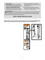
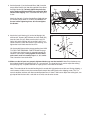
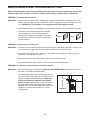
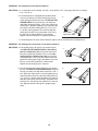
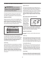
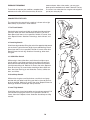
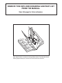
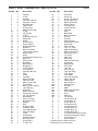
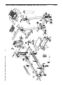
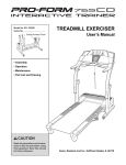
Class H Fitness Product
Model No. WETL10131
Serial No.
USER’S MANUAL
Serial Number Decal
QUESTIONS?
As a manufacturer, we are committed to providing complete
customer satisfaction. If you
have questions, or if there are
missing or damaged parts,
please call:
08457 089 009
Or write:
ICON Health & Fitness, Ltd.
Unit 4
Revie Road Industrial Estate
Revie Road, Beeston
Leeds, LS11 8JG
UK
[email protected]
CAUTION
Read all precautions and instructions in this manual before using
this equipment. Save this manual
for future reference.
Visit our website at
www.iconeurope.com
TABLE OF CONTENTS
IMPORTANT PRECAUTIONS . . . . . . . . . . . . . . . . . . . . . . . . . . . . . . . . . . . . . . . . . . . . . . . . . . . . . . . . . . . . . . . . .3
BEFORE YOU BEGIN . . . . . . . . . . . . . . . . . . . . . . . . . . . . . . . . . . . . . . . . . . . . . . . . . . . . . . . . . . . . . . . . . . . . . . .5
ASSEMBLY . . . . . . . . . . . . . . . . . . . . . . . . . . . . . . . . . . . . . . . . . . . . . . . . . . . . . . . . . . . . . . . . . . . . . . . . . . . . . . .6
OPERATION AND ADJUSTMENT . . . . . . . . . . . . . . . . . . . . . . . . . . . . . . . . . . . . . . . . . . . . . . . . . . . . . . . . . . . .10
HOW TO FOLD AND MOVE THE TREADMILL . . . . . . . . . . . . . . . . . . . . . . . . . . . . . . . . . . . . . . . . . . . . . . . . . .13
MAINTENANCE AND TROUBLESHOOTING . . . . . . . . . . . . . . . . . . . . . . . . . . . . . . . . . . . . . . . . . . . . . . . . . . . .15
CONDITIONING GUIDELINES . . . . . . . . . . . . . . . . . . . . . . . . . . . . . . . . . . . . . . . . . . . . . . . . . . . . . . . . . . . . . . .17
ORDERING REPLACEMENT PARTS . . . . . . . . . . . . . . . . . . . . . . . . . . . . . . . . . . . . . . . . . . . . . . . . . .Back Cover
Note: An EXPLODED DRAWING and a PART LIST are attached in the centre of this manual.
WESLO is a registered trademark of ICON Health & Fitness, Inc.
2
IMPORTANT PRECAUTIONS
WARNING:
To reduce the risk of burns, fire, electric shock, or injury to persons, read the
following important precautions and information before operating the treadmill.
1. It is the responsibility of the owner to ensure
that all users of this treadmill are adequately
informed of all warnings and precautions.
11. If an extension cord is needed, use only a 3conductor, 1mm2 (14-gauge) cord that is no
longer than 1.5 m (5 ft.).
2. Use the treadmill only as described in this
manual.
12. Keep the power cord away from heated surfaces.
3. Place the treadmill on a level surface, with at
least 2.5 m (8 ft.) of clearance behind it and
0.5 m (2 ft.) on each side. Do not place the
treadmill on any surface that blocks air openings. To protect the floor or carpet from damage, place a mat under the treadmill.
13. Never move the walking belt whilst the power
is turned off. Do not operate the treadmill if
the power cord or plug is damaged, or if the
treadmill is not working properly. (See
BEFORE YOU BEGIN on page 5 if the treadmill is not working properly.)
4. Keep the treadmill indoors, away from moisture and dust. Do not put the treadmill in a
garage or covered patio, or near water.
14. Never start the treadmill whilst you are standing on the walking belt. Always hold the
handrails whilst using the treadmill.
5. Do not operate the treadmill where aerosol
products are used or where oxygen is being
administered.
15. The treadmill is capable of high speeds.
Adjust the speed in small increments to avoid
sudden jumps in speed.
6. Keep children under the age of 12 and pets
away from the treadmill at all times.
16. Never leave the treadmill unattended whilst it
is running. Always remove the key and unplug
the power cord when the treadmill is not in
use.
7. The treadmill should not be used by persons
weighing more than 115 kg (250 lbs.).
17. Do not attempt to raise, lower, or move the
treadmill until it is properly assembled. (See
ASSEMBLY on page 6 and HOW TO FOLD
AND MOVE THE TREADMILL on page 13.)
You must be able to safely lift 20 kg (45 lbs.)
to raise, lower, or move the treadmill.
8. Never allow more than one person on the
treadmill at a time.
9. Wear appropriate exercise clothes when
using the treadmill. Do not wear loose clothes
that could become caught in the treadmill.
Athletic support clothes are recommended for
both men and women. Always wear athletic
shoes. Never use the treadmill with bare feet,
wearing only stockings, or in sandals.
18. When folding or moving the treadmill, make
sure that the storage latch is fully closed.
19. Do not change the incline of the treadmill by
placing objects under the treadmill.
10. When connecting the power cord (see page
10), plug the power cord into an earthed circuit. No other appliance should be on the
same circuit. When replacing the fuse, an
ASTA approved BS1362 type should be fitted
to the fuse carrier. A 13 amp fuse should be
used.
20. Inspect and properly tighten all parts of the
treadmill regularly.
21. Never drop or insert any object into any
opening.
3
22.
DANGER: Always unplug the power
other than the procedures in this manual
should be performed by an authorised service
representative only.
cord immediately after use, before cleaning
the treadmill, and before performing the maintenance and adjustment procedures described in this manual. Never remove the
motor hood unless instructed to do so by an
authorised service representative. Servicing
23. This treadmill is intended for in-home use
only. Do not use this treadmill in any commercial, rental, or institutional setting.
WARNING:
Before beginning this or any exercise program, consult your physician. This
is especially important for persons over the age of 35 or persons with pre-existing health problems.
Read all instructions before using. ICON assumes no responsibility for personal injury or property
damage sustained by or through the use of this product.
SAVE THESE INSTRUCTIONS
The decal shown has been placed on your treadmill. If the decal is missing, or if it is not legible, please
call our Customer Service Department to order a free replacement decal (see ORDERING REPLACEMENT
PARTS on the back cover of this manual). Apply the replacement decal in the location shown.
4
BEFORE YOU BEGIN
ing this manual, please call our Customer Service
Department at 08457 089 009. To help us assist you,
please note the product model number and serial number before calling. The model number of the treadmill
is WETL10131. The serial number can be found on a
decal attached to the treadmill (see the front cover of
this manual for the location of the decal).
Thank you for selecting the WESLO CADENCE® 50
treadmill. The CADENCE 50 treadmill combines advanced technology with innovative design to let you
enjoy an excellent form of cardiovascular exercise in
the convenience and privacy of your home. And when
you’re not exercising, the unique CADENCE 50 treadmill can be folded up, requiring less than half the floor
space of other treadmills.
Before reading further, please review the drawing
below and familiarise yourself with the labelled parts.
For your benefit, read this manual carefully before
using the treadmill. If you have questions after read-
Console
Water Bottle Holder
(Bottle not included)
Key/Clip
Handrail
RIGHT SIDE
Storage Latch
LEFT SIDE
Hood
Foot Pad
Walking Belt
Circuit Breaker
Front Wheel
Rear Roller
Adjustment Bolts
Incline Leg
5
ASSEMBLY
Assembly requires two persons. Set the treadmill in a cleared area and remove all packing materials; do not
dispose of the packing materials until assembly is completed. Assembly requires the included hex key
and your own phillips screwdriver
and adjustable spanners
.
For help identifying the assembly hardware, refer to the drawings below. Note: The assembly hardware and
other small parts are packaged in separate part bags. Do not open the part bags until instructed to do so.
U-nut (105)–4
Silver Ground
Screw (87)–1
1/4” Washer
(107)–4
5/16” Washer
(31)–4
3/8” Star Washer
(45)–2
1/2” Screw (84)–2
Crossbar Screw (69)–2
3/4” Screw (90)–10
3” Bolt (2)–4
1” Bolt (12)–4
5” Bolt (10)–2
1
WARNING: Do not plug in the power
1a
cord until the treadmill is completely assembled.
Hole
89
1. Open part bag A. Identify the Right Upright (89), which
has a large round hole near the lower end.
See drawing 1a. Slide two U-nuts (105) into the lower
end of the Right Upright (89) as shown. Insert two Unuts into the Left Upright (not shown) in the same
way.
See drawing 1b. Attach the Left and Right Uprights (88,
89) to the Base (71) with four 3” Bolts (2) and four 5/16”
Washers (31). Make sure that the Uprights are oriented so the indicated plates are facing each other.
In addition, make sure that the Base is oriented so
the Base Pads (19) are in the location shown.
89
105
1b
88
31
Plates
89
31
19
2
19
6
2
71
2. Open part bag B. Press the Right Frame Spacer (13) and
the Left Frame Spacer (not shown) onto the sides of the
Frame (55) as shown. Make sure that the high side of
each Spacer is facing forward as shown. With the help
of a second person, carefully lift the Frame and hold the
Spacers between the plates on the Uprights (89).
2
Wide
side
Plate
Align the hole in the plate on the Right Upright (89) with
the hole in the Right Frame Spacer (13). Loosely thread a
5” Bolt (10) and a 3/8” Star Washer (45) into the Spacer
and the Frame (55). Repeat this step on the left side of
the treadmill.
See drawing 2a. With the help of a second person, carefully tip the treadmill onto its left side as shown.
45
13
10
89
55
2a
89
Feed the Wire Harness (22) into the large round hole near
the lower end of the Right Upright (89), and then pull the
Wire Harness out of the upper end as shown.
22
22
3. Open part bag C. With the help of a second person,
raise the Left and Right Uprights (88, 89) to the vertical
position.
3
7
22
Hole
Identify the Right Handrail (6), which has a large hole in
the left side. Feed the Wire Harness (22) into the rectangular bracket on the Right Handrail and out of the large
hole. Note: It may be helpful to use needlenose pliers to
pull the Wire Harness out of the hole.
12
107
12
6
88
Insert the rectangular bracket on the Right Handrail (6)
into the right Upright (89). Attach the Right Handrail with
two 1” Bolts (12) and two 1/4” Washers (107) as shown.
Do not tighten the Bolts yet.
Attach the Left Handrail (7) as described above. Note:
There is not a wire harness on the left side.
12
107
4
Small Bracket
75
22
4. See the inset drawings and identify the two Crossbar
Screws (69); be careful not to confuse the Crossbar
Screws with the 3/4” Screws (90).
Hold the Crossbar (75) on the small brackets on the
Handrails (6, 7). Attach the Crossbar to the small brackets with the two Crossbar Screws (69). Do not tighten
the Crossbar Screws yet.
89
12
69
87
7
Small Bracket
69
6
Attach the end of the ground wire to the small hole in the
side of the Right Handrail (6) with a Silver Ground Screw
(87).
69
7
90
5. Open part bag D. Place the Console Base (100) on the
Right Handrail (6) and the Left Handrail (not shown).
Attach the Console Base with four 3/4” Screws (90) (only
two Screws are shown). Do not tighten the Screws yet.
5
100
22
Insert the Wire Harness (22) through the two indicated
plastic ties on the Console Base (100). Next, insert the
Wire Harness up through the opening beside the Wire
Cover (86). Make sure that the Wire Cover is securely attached to the Console Base.
See drawing 5a. Look at the top of the Console Base
(100). Insert the Wire Harness (22) through the plastic tie
on top of the Console Base.
86
Ties
90
6
5a
22
Tie
100
6. Press the Book Rack (85) onto the Console Base (100) in
the location shown.
6
85
100
7. Hold the Console (1) near the Console Base (100).
Touch the Right Handrail (6) to discharge any static.
Find the connector on the end of the Wire Harness (22).
Insert the connector into the red socket beneath the
Console. The connector should slide easily into the
socket and snap into place. If the connector does
not slide easily and snap into place, turn the connector and then insert it. Make sure that the connector and
wires appear as shown in drawing 7a.
7
22
1
Ties
See drawing 5a. Insert the excess Wire Harness (22)
down into the opening in the Console Base (100).
Securely tighten the plastic tie on top of the Console
Base to prevent the Wire Harness from slipping.
Then, cut off the end of the plastic tie.
100
6
7a
22
8
8. Set the Console (1) on the Console Base (100). Insert the
excess Wire Harness (22) into the large hole in the side of
the Right Handrail (6). Securely tighten the plastic ties
on the bottom of the Console Base to prevent the Wire
Harness from slipping. Then, cut off the ends of the plastic ties.
8
1
100
Ties
Attach the Console (1) to the Console Base (100) with four
3/4” Screws (90) and two 1/2” Screws (84). Start all six
Screws before tightening them; do not overtighten
the Screws.
6
9. Attach the Latch Housing (41) to the Left Upright (88)
with two 3/4” Screws (90). Remove the Latch Knob (95)
from the Latch Pin (91). Make sure that the Latch Pin
Collar (93) and the Spring (94) are on the Latch Pin as
shown. Insert the Latch Pin into the Latch Housing, and
tighten the Latch Knob onto the Latch Pin.
Lift the treadmill frame to the storage position (see HOW
TO FOLD THE TREADMILL FOR STORAGE on page
13). Make sure that the frame is centered between the
Handrails (not shown). Firmly tighten all of the bolts
and screws used in assembly steps 2, 3, 4, 5, and 8.
Then, lower the frame to the floor.
90
90
84
9
88
41
95
Large
Hole
94
90
93
91
10. Make sure that all parts are properly tightened before you use the treadmill. Note: Extra hardware may
be included. Keep the included hex keys in a secure place. The large hex key is used to adjust the walking
belt (see page 16). To protect the floor or carpet, place a mat under the treadmill.
Note: The underside of the treadmill walking belt is coated with high-performance lubricant. During shipping, a
small amount of lubricant may be transferred to the top of the walking belt or the shipping carton. This is a
normal condition and does not affect treadmill performance. If there is lubricant on top of the walking belt, simply wipe off the lubricant with a soft cloth and a mild, non-abrasive cleaner.
9
OPERATION AND ADJUSTMENT
THE PERFORMANT LUBETM WALKING BELT
Your treadmill features a walking belt coated with PERFORMANT LUBETM, a high-performance lubricant. IMPORTANT: Never apply silicone spray or other substances to the walking belt or the walking platform. Such
substances will deteriorate the walking belt and cause excessive wear.
HOW TO PLUG IN THE POWER CORD
This product must be earthed. If it should malfunction or break
down, earthing provides a path of least resistance for electric
current to reduce the risk of electric shock. This product is equipped
with a cord having an equipment-earthing conductor and an earthing plug.
Two power cords are included. Select the one that will fit your
outlet. Refer to drawing 1. Plug the indicated end of the power
cord into the socket on the treadmill. Next, lift the tab on the
ferrite box and clamp the ferrite box around the power cord.
Fasten the included plastic tie just behind the ferrite box and
cut off the excess plastic tie. This will prevent the ferrite box
from sliding along the power cord. Refer to drawing 2. Plug the
power cord into an appropriate outlet that is properly installed
and earthed in accordance with all local codes and ordinances.
Note: In Italy, an adaptor (not included) must be used between
the power cord and the outlet. Important: The treadmill is not
compatible with GFCI-equipped outlets.
1
Socket on treadmill
Ferrite Box
Plastic
Tie
Tab
2
Outlet
If the power cord is damaged, it must be replaced with a manufacturer-recommended power cord.
DANGER:
Improper connection of the equipment-earthing conductor can result in an increased risk of electric shock. Check with a qualified electrician or serviceman if you are in doubt as
to whether the product is properly earthed. Do not modify the plug provided with the product—if it
will not fit the outlet, have a proper outlet installed by a qualified electrician.
10
CONSOLE DIAGRAM
Displays
Note: If there is a thin sheet of
plastic on the console, remove it.
Key
Clip
Insert the key fully into the console. After a moment,
the displays will light. Test the clip by carefully taking a few steps backward until the key is pulled
from the console. If the key is not pulled from the
console, adjust the position of the clip.
CAUTION:
Before operating the
console, read the following precautions.
• Do not stand on the walking belt when turning on the power.
Follow the steps below to operate the console.
• Always wear the clip (see the drawing
above) while operating the treadmill.
1
• Adjust the speed in small increments to
avoid sudden jumps in speed.
Insert the key fully into the console.
A few seconds after the key is inserted, the displays will light.
• To reduce the possibility of electric shock,
keep the console dry. Avoid spilling liquids
on the console and place only a sealed
water bottle in the water bottle holder.
2
Press the Start button or the Speed s button to
start the walking belt.
A moment after the button is pressed, the walking
belt will begin to move. Hold the handrails and
begin walking.
STEP-BY-STEP CONSOLE OPERATION
As you exercise, change the speed of the walking
belt as desired by pressing the Speed buttons.
Each time a button is pressed, the speed setting
will change by 0.1 mph; if a button is held down,
the speed setting will change in increments of 0.5
mph. Note: The console can display speed and
distance in either miles or kilometers (see
SPEED DISPLAY on page 12). For simplicity, all
instructions in this section refer to miles.
Before operating the console, make sure that the
power cord is properly plugged in (see page 10).
Next, stand on the foot rails of the treadmill. Find the
clip attached to the key (see the drawing above), and
slide the clip onto the waistband of your clothes.
11
To stop the walking belt, press the Stop button.
The elapsed time will begin to flash in the Time
display.
move the key, and then reinsert the key.
4
Note: During the first few minutes that the treadmill is used, inspect the alignment of the walking
belt, and align it if necessary (see page 16).
3
When you are finished exercising, remove the
key.
Step onto the foot rails, press the Stop button, and
remove the key from the console. Keep the key in
a secure place.
Follow your progress with the four displays.
HOW TO CHANGE THE INCLINE OF THE TREADMILL
Time display—This display shows the elapsed
time. When the Stop button is pressed, the
elapsed time will flash.
Distance display—This
display shows the distance that you have
walked or run.
To vary the intensity of your exercise, the incline of the
treadmill can be changed. There are four incline levels.
Before changing the incline, remove the key and
unplug the power cord.
Next, fold the treadmill to the storage position (see
HOW TO FOLD THE TREADMILL FOR STORAGE on
page 13).
To change the incline, first pull one of the incline legs
Speed display—This
display shows the speed
of the walking belt.
Fat Calories/Calories
Mode Indicator
display—This display
shows the approximate
numbers of fat calories
and calories you have
burned (see FAT BURNING on page 17). The
display will change from
one number to the other every few seconds, as
shown by the mode indicators.
Note: The console can
display speed and distance in either miles or
kilometers. To change
the unit of measurement,
hold down the Stop button, insert the key into the console, and continue
to hold the Stop button for a moment. An “E” for
English miles or an “M” for metric kilometers will
appear in the Fat Calories/Calories display. Press
the Speed s button to change the unit of measurement. When the desired unit of measurement
is selected, remove the key and then reinsert it.
Arrow
Button
Housing
Incline
Leg
out of its housing as shown at the right. Rotate the incline leg to a different position and press in on the indicated button as you reinsert the incline leg. An arrow
on the housing will point to one of four numbers on the
bottom of the incline leg. Position 1 is the lowest incline level, and position 4 is the highest. Adjust the
other incline leg in the same way. CAUTION:
Before using the treadmill, make sure that both incline legs are in the same position.
After you have adjusted the incline legs, lower the
treadmill (see HOW TO LOWER THE TREADMILL
FOR USE on page 14).
To reset the displays, press the Stop button, re-
12
HOW TO FOLD AND MOVE THE TREADMILL
HOW TO FOLD THE TREADMILL FOR STORAGE
Unplug the power cord. CAUTION: You must be able to
safely lift 20 kg (45 lbs.) to raise, lower, or move the
treadmill.
1. Hold the treadmill with your hands in the locations shown
at the right. CAUTION: To decrease the possibility of injury, bend your legs and keep your back straight. As
you raise the treadmill, make sure to lift with your legs
rather than your back. Raise the treadmill about halfway
to the vertical position.
2. Move your right hand to the position shown and hold the
treadmill firmly. Using your left hand, pull the latch knob to
the left and hold it. Raise the treadmill until the frame
passes the latch pin. Slowly release the latch knob. Make
sure that the frame is securely held by the latch pin.
To protect the floor or carpet from damage, place a
mat under the treadmill. Keep the treadmill out of direct sunlight. Do not leave the treadmill in the storage
position in temperatures above 30° C (85° F).
Latch
Knob
Latch
Pin
HOW TO MOVE THE TREADMILL
Before moving the treadmill, convert the treadmill to the storage position as described above. Make sure that the latch
pin is fully inserted into the hole in the handrail and
locked into place as described above.
1. Hold the handrails and place one foot on the base as
shown.
2. Tilt the treadmill back until it rolls freely on the front wheels.
Carefully move the treadmill to the desired location. Never
move the treadmill without tipping it back. To reduce
the risk of injury, use extreme caution whilst moving
the treadmill. Do not attempt to move the treadmill
over an uneven surface.
3. Place one foot on the base, and carefully lower the treadmill until it is resting in the storage position.
13
Base
Front Wheels
HOW TO LOWER THE TREADMILL FOR USE
1. Hold the upper end of the treadmill with your right hand as
shown. Using your left hand, pull the latch knob to the left
and hold it. Pivot the treadmill down until the frame is past
the latch pin. Slowly release the latch knob.
Latch
Knob
Latch
Pin
2. Hold the treadmill firmly with both hands, and lower the
treadmill to the floor. To decrease the possibility of injury, bend your legs and keep your back straight.
14
MAINTENANCE AND TROUBLESHOOTING
Most treadmill problems can be solved by following the steps below. Find the symptom that applies, and
follow the steps listed. If further assistance is needed, please call our Customer Service Department.
PROBLEM: The power does not turn on
SOLUTION: a. Make sure that the power cord is plugged into a properly earthed outlet. (See page 10.) If an extension cord is needed, use only a 3-conductor, 1mm2 (14-gauge) cord that is no longer than 1.5 m
(5 ft.). IMPORTANT: The treadmill is not compatible with GFCI-equipped outlets.
b. After the power cord has been plugged in, make sure that the key is fully inserted into the console.
c. Check the circuit breaker located on the treadmill
near the power cord. If the switch protrudes as
shown, the circuit breaker has tripped. To reset the
circuit breaker, wait for five minutes and then press
the switch back in.
c
Tripped
Reset
Tripped
Reset
PROBLEM: The power turns off during use
SOLUTION: a. Check the circuit breaker located on the treadmill frame near the power cord (see c. above). If the
circuit breaker has tripped, wait for five minutes and then press the switch back in.
b. Make sure that the power cord is plugged in. If the power cord is plugged in, unplug it, wait for
five minutes, and then plug it back in.
c. Remove the key from the console. Reinsert the key fully into the console.
d. If the treadmill still will not run, please call our Customer Service Department.
PROBLEM: The displays of the console do not function properly
SOLUTION: a. Remove the key from the console and UNPLUG THE POWER CORD. Remove the screws from
the hood, and carefully remove the hood.
Locate the Reed Switch (46) and the Magnet (49) on
the left side of the Pulley (53). Turn the Pulley until the
Magnet is aligned with the Reed Switch. Make sure
that the gap between the Magnet and the Reed
Switch is about 3 mm (1/8 in.). If necessary, loosen
the Screw (26) and move the Reed Switch slightly.
Retighten the Screw. Re-attach the hood, and run the
treadmill for a few minutes to check for a correct
speed reading.
15
3 mm
53
49
46
Top View
PROBLEM: The walking belt slows when walked on
SOLUTION: a. If an extension cord is needed, use only a 3-conductor, 1mm2 (14-gauge) cord that is no longer
than 1.5 m (5 ft.).
b. If the walking belt is overtightened, treadmill performance may decrease and the walking belt may become damaged. Remove the key and UNPLUG THE
POWER CORD. Using the hex key, turn both rear
roller bolts counterclockwise, 1/4 of a turn. When the
walking belt is properly tightened, you should be able
to lift each side of the walking belt 5 to 7 cm (2 to 3
in.) off the walking platform. Be careful to keep the
walking belt centred. Plug in the power cord, insert
the key and run the treadmill for a few minutes.
Repeat until the walking belt is properly tightened.
b
5–7 cm
Rear Roller
Adjustment Bolts
c. If the walking belt still slows when walked on, please call our Customer Service Department.
PROBLEM: The walking belt is off-centre or slips when walked on
SOLUTION: a. If the walking belt is off-centre, first remove the key
and UNPLUG THE POWER CORD. If the walking
belt has shifted to the left, use the hex key to turn
the left rear roller bolt clockwise 1/2 of a turn; if the
walking belt has shifted to the right, turn the bolt
counterclockwise 1/2 of a turn. Be careful not to overtighten the walking belt. Plug in the power cord, insert
the key, and run the treadmill for a few minutes.
Repeat until the walking belt is centered.
b. If the walking belt slips when walked on, first remove
the key and UNPLUG THE POWER CORD. Using the
hex key, turn both rear roller bolts clockwise, 1/4 of a
turn. When the walking belt is correctly tightened, you
should be able to lift each side of the walking belt 5 to
7 cm (2 to 3 in.) off the walking platform. Be careful to
keep the walking belt centred. Plug in the power cord,
insert the key, and walk on the treadmill for a few minutes. Repeat until the walking belt is properly tightened.
16
a
b
CONDITIONING GUIDELINES
Aerobic Exercise
WARNING:
Before beginning
this or any exercise program, consult your
physician. This is especially important for individuals over the age of 35 or individuals
with pre-existing health problems.
The following guidelines will help you to plan your exercise program. For more detailed exercise information, obtain a reputable book or consult your physician.
If your goal is to strengthen your cardiovascular system, your exercise must be “aerobic.” Aerobic exercise
is activity that requires large amounts of oxygen for
prolonged periods of time. This increases the demand
on the heart to pump blood to the muscles, and on the
lungs to oxygenate the blood. For aerobic exercise,
adjust the speed and incline of the treadmill until your
heart rate is near the highest number in your training
zone.
HOW TO MEASURE YOUR HEART RATE
EXERCISE INTENSITY
Whether your goal is to burn fat or to strengthen your
cardiovascular system, the key to achieving the desired
results is to exercise with the proper intensity. The
proper intensity level can be found by using your heart
rate as a guide. The chart below shows recommended
heart rates for fat burning and aerobic exercise.
To measure your
heart rate, stop exercising and place
two fingers on your
wrist as shown.
Take a six-second
heartbeat count,
and multiply the result by ten to find
your heart rate. (A six-second count is used because
your heart rate drops quickly when you stop exercising.) If your heart rate is too high or too low, adjust the
speed or incline of the treadmill accordingly.
WORKOUT GUIDELINES
Each workout should include the following three important parts:
To find the proper heart rate for you, first find your age
at the top of the chart (ages are rounded off to the
nearest ten years). Next, find the three numbers below
your age. The three numbers are your “training zone.”
The lower two numbers are recommended heart rates
for fat burning; the highest number is the recommended heart rate for aerobic exercise.
A Warm-up
Fat Burning
Training Zone Exercise
To burn fat effectively, you must exercise at a relatively
low intensity level for a sustained period of time. During
the first few minutes of exercise, your body uses easily
accessible carbohydrate calories for energy. Only after
the first few minutes does your body begin to use
stored fat calories for energy. If your goal is to burn fat,
adjust the speed and incline of the treadmill until your
heart rate is near one of the lower two numbers in your
training zone.
After warming up, increase the intensity of your exercise until your pulse is in your training zone for 20 to
60 minutes. (During the first few weeks of your exercise program, do not keep your pulse in your training
zone for longer than 20 minutes.) Breathe regularly
and deeply as you exercise—never hold your breath.
Warming up prepares the body for exercise by increasing circulation, delivering more oxygen to the muscles
and raising the body temperature. Begin each workout
with 5 to 10 minutes of stretching and light exercise to
warm up (see SUGGESTED STRETCHES on page 18).
A Cool-down
Finish each workout with 5 to 10 minutes of stretching
to cool down. This will increase the flexibility of your
muscles and will help to prevent post-exercise problems.
17
EXERCISE FREQUENCY
tween workouts. After a few months, you may complete up to five workouts each week if desired. The key
to success is to make exercise a regular and enjoyable
part of your everyday life.
To maintain or improve your condition, complete three
workouts each week, with at least one day of rest be-
SUGGESTED STRETCHES
1
The correct form for several basic stretches is shown at the right.
Move slowly as you stretch—never bounce.
1. Toe Touch Stretch
Stand with your knees bent slightly and slowly bend forward from
your hips. Allow your back and shoulders to relax as you reach
down toward your toes as far as possible. Hold for 15 counts, then
relax. Repeat 3 times. Stretches: Hamstrings, back of knees, and
back.
2
2. Hamstring Stretch
Sit with one leg extended. Bring the sole of the opposite foot toward
you and rest it against the inner thigh of your extended leg. Reach
toward your toes as far as possible. Hold for 15 counts, then relax.
Repeat 3 times for each leg. Stretches: Hamstrings, lower back,
and groin.
3
3. Calf/Achilles Stretch
With one leg in front of the other, reach forward and place your
hands against a wall. Keep your back leg straight and your back
foot flat on the floor. Bend your front leg, lean forward and move
your hips toward the wall. Hold for 15 counts, then relax. Repeat 3
times for each leg. To cause further stretching of the achilles tendons, bend your back leg as well. Stretches: Calves, achilles tendons, and ankles.
4
4. Quadriceps Stretch
With one hand against a wall for balance, reach back and grasp
one foot with your other hand. Bring your heel as close to your buttocks as possible. Hold for 15 counts, then relax. Repeat 3 times for
both legs. Stretches: Quadriceps and hip muscles.
5. Inner Thigh Stretch
Sit with the soles of your feet together and your knees outward. Pull
your feet toward your groin area as far as possible. Hold for 15
counts, then relax. Repeat 3 times. Stretches: Quadriceps and hip
muscles.
18
5
NOTES
19
ORDERING REPLACEMENT PARTS
If you encounter any problems with this product, or if you need to order replacement parts, contact the ICON
Health & Fitness Ltd. office, or write:
ICON Health & Fitness, Ltd.
Customer Service Department
Unit 4, Revie Road Industrial Estate
Beeston
Leeds, LS11 8JG
UK
Tel:
08457 089 009
Outside the UK: 0 (444) 113 387 7133
Fax: 0 (444) 113 387 7125
When ordering parts, please be prepared to give the following information:
• the MODEL NUMBER of the product (WETL10131)
• the NAME of the product (WESLO® CADENCE 50 treadmill)
• the SERIAL NUMBER of the product (see the front cover of this manual)
• the KEY NUMBER and DESCRIPTION of the part(s) (see the PART LIST and the EXPLODED DRAWING in
the centre of this manual)
Part No. 197481 R1003A
Printed in Canada © 2003 ICON Health & Fitness, Inc.
REMOVE THIS PART LIST/EXPLODED
REMOVE
THIS EXPLODED
DRAWING
AND PART LIST
DRAWING
FROM THE
MANUAL!
FROM THE MANUAL.
34
Save this page for future reference.
Note: Specifications are subject to change without notice. For information about
ordering replacement parts, see the back cover of the User’s Manual.
PART LIST—Model No. WETL10131
Key No. Qty.
1
2
3
4
5
6
7
8
9
10
11
12
13
14
15
16
17
18
19
20
21
22
23
24
25
26
27
28
29
30
31
32
33
34
35
36
37
38
39
40
41
42
43*
44
45
46
47
48
49
50
51
52
53
54
55
56
57
59
60
61
1
4
1
1
12
1
1
1
2
2
2
4
1
2
2
2
1
1
4
4
1
1
1
10
1
4
2
2
1
1
4
1
1
1
1
1
1
1
1
1
1
2
1
1
2
1
1
1
1
1
2
6
1
1
1
1
1
1
1
5
R1003A
Description
Key No. Qty.
Description
Console
3” Bolt
Key/Clip
Left Frame Spacer
Electronics Screw
Right Handrail
Left Handrail
Battery Cover
Motor Tension Bolt
5” Bolt
3/8” Washer
1” Bolt
Right Frame Spacer
Wheel Bolt
Wheel
Base Endcap
Warning Decal
Upright Grommet
Base Pad
Belly Pan Screw
Large Warning Decal
Wire Harness
Hood
Hood Screw/Clamp Screw
Belly Pan
Small Screw
Belt Guide
Roller Spacer
Receptacle
Circuit Breaker
5/16” Washer
Controller Bracket
Filter
Choke
Controller
Motor Pivot Bolt
Foot Pad (Left)
Motor Tension Nut
Star Washer
Motor Tension Washer
Latch Housing
Wheel Nut
Motor Assembly
Euro Power Cord Set
3/8” Star Washer
Reed Switch
Wire Tie Clamp
Reed Switch Clip
Magnet
Belt
Roller Adj. Bolt
Platform Screw
Front Roller/Pulley
Foot Pad (Right)
Frame
Walking Belt
Walking Platform
Ground Screw
Ground Wire
8” Cable Tie
62
1
Ferrite Box
63
2
Incline Leg
64
2
Incline Leg Housing
65
4
Incline Leg Screw
66
2
Roller Adj. Washer
67
2
Frame Endcap
68
6
Endcap Screw
69
2
Crossbar Screw
70
4
Cage Nut
71
1
Base
72
1
Rear Roller
73
4
Base Pad Screw
74
1
Hex Key
75
1
Crossbar
76
1
Ground Screw
77
1
Ground Star Washer
78
1
Ground Nut
79
3
Nylon Washer
80
2
1 1/2” x 3” Plate
81
1
Motor Pivot Sleeve
82
2
Motor Pivot Bushing
83
2
Handrail Endcap
84
2
1/2” Screw
85
1
Book Rack
86
1
Wire Cover
87
1
Silver Ground Screw
88
1
Left Upright
89
1
Right Upright
90
10
3/4” Screw
91
1
Latch Pin
92
1
Latch Pin Clip
93
1
Latch Pin Collar
94
1
Latch Spring
95
1
Latch Knob
96
1
Latch Pin Assembly
97
4
Plastic Standoff
98
1
Power Board
99
1
Warning Decal
100
1
Console Base
101
1
Flywheel
102
1
Motor
103
1
Motor Controller Wire
104
1
On/Off Switch
105
4
U-nut
106
1
Hole Plug
107
4
1/4” Washer
#
1
14” Blue Wire, 2F
#
1
8” Blue Wire, 2F
#
1
4” Blue Wire, 2F
#
1
4” Blue Wire, M/F
#
1
10” White Wire, 2F
#
1
8” White Wire, 2F
#
1
4” White Wire, 2F
#
1
4” White Wire, M/F
#
1
12” Green/Yellow Wire, F/Ring
#
1
4” Green/Yellow Wire, F/Ring
#
1
4” Black Wire, 2F
#
1
User’s Manual
* Includes all parts shown in the box
# These parts are not illustrated
R0203A
51
68
66
80
63
67
64
74
51
65
21
37
66
67
68
72
52
64
80
26
27
57
56
63
65
54
52
28
49
59
60
55
48
46
26
47
52
61
26
81
39
102
79
40
42 82
50
53
101
9
EXPLODED DRAWING—Model No. WET10130
WETL21021
79
27
24
28
5
33
82
43*
38
R0603A
36
5
20
5
103
62
34
106
32
35
23
5
30
44
95
96*
98
14
90
91
70
90
42
19
73
105
45
71
11
10
41
12 107
7
93
33
104 15
25
94
92
97
83
20
29
24
75
34
107
2
31
16
42
4
22
90
19
73
15
105
88
83
69
12
1
78
22
6
17
14
13
76
77
18
12 107
69
70
87
8
90
19
73
31
2
45
11
12
90
89
107
84
3
73
19
105
10
90
16
100
85
86
EXPLODED DRAWING—Model No. WETL10131
R1003A
??