1
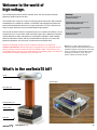
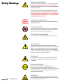
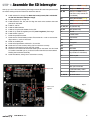
© 2015 oneTesla LLC
oneTeslaTS DIY Tesla Coil Kit
User Manual v1.4
User Manual v1.4
1
Running list of errata
You are currently reading version 1.4 of the oneTeslaTS User Manual. Before continuing, go to onetesla.com/downloads and check
that v1.4 is the most up-to-date version. If not, download the errata or the latest version of the manual. This page will be continuously
updated with corrections.
March 2015
Some early kits will have 47mm tall 1000uF bus capacitors,
while others will have shorter capacitors. One of the screws in
the bottom secondary endcap bumps into the tall capacitor by a
fraction of a millimeter. We recommend omitting the third screw
in the endcap, as is noted in step 10. It will not affect mechanical
stability of the secondary.
Note that there are two incorrectly printed part values on the SD
interrupter board: a 1K resistor which should be 100 ohms, and a
7805L that should be a 7833. See step 1 for details.
There may be a few extra M3 6mm screws in your kit.
In Step 5, the color code of R4 was incorrectly listed as 3.3K
(orange orange red). The correct resistor is 3.3Ω (orange orange
gold gold).
In Step 5, IC4 was incorrectly listed as UCC37322. It has been
corrected to UCC37321. All references to UCC37322 have been
changed to UCC37321.
April 2015
Double-check that your sil-pads are large enough to cover the
entire IGBT as it’s possible that some smaller sil-pads got
included in your kit accidentally. Contact us for the correct size
sil-pads if this is the case.
In Step 5-J, regarding the fiber optic receiver, kit builders have
noticed that soldering this component at too high a temperature
can damage it. We are not exactly sure of the proper temperature
range, but we recommend soldering at no higher than 400°C.
June 2015
In Step 10, added more detailed end cap assembly instructions
and diagrams.
User Manual v1.4
2
Welcome to the world of
high voltage.
You’ve made a good choice with the oneTesla TS kit, the most compact and highperforming Tesla coil kit you will find.
The oneTesla TS is a respin of our first, immensely popular Tesla coil kit. We’ve listened
to feedback from hundreds of oneTesla v1 kit builders and redesigned the electronics
and mechanical assembly with a focus on easy construction. You don’t need to be an
expert in power electronics to get yourself beautiful singing sparks!
How well the kit works, however, is dependent upon your careful workmanship. This is a
complex kit, so it’s not unusual to need a few tries to get it right. Hardware construction
requires attention to detail, and patience in tracking down problems. Solder carefully,
follow the instructions closely, and don’t be afraid ask for help when you need it. Be
patient and persistent, and you’ll learn a lot and have a successful build.
Read and understand the entire manual, as well as tutorials on our website at
onetesla.com/tutorials, before beginning! It’s important that you understand how the
Tesla coil works in order to build it correctly and handle it safely. Ensure that you are
comfortable working with all of the hazards listed on the following pages. You should not
construct this kit without supervision if you are under 18.
Need help?
Go to our support forum at
onetesla.com/forum
Need replacement parts? Contact us at
[email protected]
Check out all of our educational tutorials at
onetesla.com/tutorials
Check out our other kits at
www.onetesla.com!
Note: We try our best to keep all images and
instructions consistent with the latest revision of the
oneTeslaTS hardware, but the photos in this manual
and on our website are not always identical to the
components you receive in your kit. They will,
however, maintain the same functionality.
What’s in the oneTeslaTS kit?
Toroid
SD Interrupter
secondary coil
etched primary coil
chassis PCBs
heat sink
User Manual v1.4
3
Electrical Safety Warning
Safety Warnings
The Tesla coil creates extremely high voltage and high frequency
sparks. NEVER TOUCH THE OUTPUT OF THE TESLA COIL.
At best, you will get a nasty burn; at worst, you’ll get a potentially
life-threatening shock.
The Tesla coil’s control board is also dangerous while the bus
capacitors are charged. NEVER SERVICE THE BOARD WHILE
IT IS POWERED ON. ALWAYS WAIT AT LEAST FIVE MINUTES
AFTER THE BOARD IS POWERED OFF FOR CAPACITORS TO
DISCHARGE BEFORE SERVICING.
ADULT
SUPERVISION
REQUIRED
Adult Supervision Required
Users under 18 should only use this kit under the supervision of
an experienced adult.
Pacemaker Warning
Persons with electronic medical implants such as pacemakers
should not be near the Tesla coil during operation. EMI from the
coil may interfere with the pacemaker’s function.
Ear Protection Recommended
The Tesla coil output is loud. Ear protection is recommended.
ADULT
SUPERVISION
REQUIRED
ADULT
SUPERVISION
REQUIRED
ADULT
SUPERVISION
REQUIRED
Ozone Warning
The high temperature of the Tesla coil streamers causes the
gases that make up air to form other compounds, including ozone
(which can often be smelled when the coil is in operation) and
nitrogen oxides. Keep the Tesla coil work area well-ventilated to
prevent the buildup of irritating gases such as ozone and nitrogen
oxides, which become toxic if concentrated.
Fire Hazard
The arcs from the Tesla coil can set flammable objects on fire.
Keep all flammable objects away from the Tesla coil while it is
in operation.
ADULT
SUPERVISION
ADULT
REQUIRED
SUPERVISION
REQUIRED
Eye Glasses Required
Always wear eye protection while soldering. Power
semiconductors may overheat and fail violently, causing a
shrapnel hazard. Wear safety glasses when working on the board
while it is energized. Only power up the board when it is fully
enclosed inside the chassis.
RF Warning
User Manual v1.4
Keep sensitive electronics away from the Tesla coil at all times.
Use the entire length of the included fiber optic cable to distance
your computer from the Tesla coil.
4
Before you begin
Be up-to-date
Ensure you have the latest version of the manual, and
if not, download the errata sheet or the newest version at
onetesla.com/downloads.
Read the tutorials
All of our tutorials can be found at onetesla.com/tutorials
nSoldering tutorial
(onetesla.com/tutorials/how-to-solder)
nDe-soldering tutorial
(onetesla.com/tutorials/how-to-desolder)
nHow a Tesla coil works
(onetesla.com/tutorials/how-a-tesla-coil-works)
Observe good workspace practices
nKeep your workspace neat and orderly.
nAlways obey common sense.
nDo not continue work if at any point you feel
uncomfortable with the hazards a challenging electronics
project poses.
nUse caution when soldering. Lead is hazardous, and
the iron is extremely hot.
Have the right equipment
Having the proper tools for electronic assembly, particularly a
powerful enough soldering iron, will make your life much easier!
Here are the tools you need to assemble your Tesla coil:
ntemperature-controlled soldering iron, 40W minimum
nrosin-core solder of an appropriate thickness
nsafety glasses
nsmall pliers
nflush cutters
nwire strippers
nsmall screwdriver
nhot glue gun
nmultimeter
n spray-on or paint-on varnish
Optional but useful:
npacking tape
n masking tape
n solder wick or other desoldering tools
noscilloscope and power supply
Safely work with electrical hazards
Always be in control of the power source. Have the plug within
your reach at all times.
Wait 5 minutes after unplugging the driver board for capacitors to
discharge before servicing the board.
When debugging, don’t wear jewelry that could accidentally come
into contact with circuitry and cause short-circuits.
Never work on something dangerous when you’re alone.
If you feel tired or uncomfortable at any point, take a break and
come back to your work later.
If you have any hesitation about the nature of the high voltage
circuits you are probing, work with one hand in your pocket. This
prevents you from inadvertently touching a grounded object with
your other hand when probing something that is potentially high
voltage, which could cause a short-circuit across your chest.
Ask for help when you need it! Better to ask a question in advance
than do something damaging or dangerous. We’re here to help on
onetesla.com/forum.
User Manual v1.4
5
Step 1:
Assemble the SD Interrupter
Heat up your iron! Let’s start soldering. We’ll begin with the SD card interrupter because
we need it working to test the Tesla coil’s electronics later on.
A.
B.
C.
D.
E.
F.
G.
H.
I.
J.
K.
L.
M.
N.
O.
P.
Install resistors R1 through R10. Note that in early boards, R9 is mislabeled as 1kΩ and should be 100Ω (see image)!
Install capacitors C1 through C5.
Install sockets for IC2, IC3, and IC4. Align the notch on the socket to the notch pictured on the board.
Install D1 and D2.
Install the slide switches.
Install the 16-pin female header for the LCD.
Install IC1 (a 78L05 5V regulator) and IC5 (a 3.3 V regulator). See image.
Install 16MHz crystal Y1.
Install the optical transmitter.
Install the two CR123A battery holders. Ensure that the + mark on each socket aligns with the + mark on the board!
Install J2, the MIDI jack.
Install the tall pushbutton switches S1, S2, and S3.
Install the ICs in their sockets, taking care to orient them correctly.
Solder the male header pins into the LCD module.
Place the LCD module into the female header pins on the board. You don’t need to install the standoffs yet, as you should confirm that the board works before finishing the mechanical assembly.
Install the batteries, taking care to orient them correctly.
R1, R10
10kΩ (brown black orange)
R2, R7, R8
1kΩ (brown black red)
R3, R9
100Ω (brown black brown)
(note that on early boards, R9
is mislabeled)
R4
100kΩ (brown black yellow)
R5
3.3kΩ (orange orange red)
R6
220Ω (red red brown)
C1, C2, C5
1uF (labeled 105)
C3, C4
18pF (labeled 180)
D1
1N4148
2x Slide switch
LCD headers
IC1
7805
IC2
ATMega328
IC3
4N25
IC4
74HC4050
IC5
3.3V regulator (note that
early boards are mislabeled)
Y1
16MHz crystal
Fiber optic transmitter
R9 is 100Ω
IC5 is a 3.3V
regulator
User Manual v1.4
2x CR123A battery holder
J2
MIDI jack
S1, S2, S3
Tall tactile switch
Step N.
6
Step 2:
Test the SD Interrupter
Power on the interrupter. Depending on whether or not you have a micro SD card installed, you should be greeted with either “Fixed
Mode” or “No SD card found” on the display. Press [Down] until you see “Fixed Mode”, then press [Select] to launch fixed mode. Look
into the optical transmitter and verify that you see a blinking red light. If you do, hooray, your interrupter works! Proceed to step 3.
If no display is
present...
If no backlight is
present...
Lack of a backlight indicates that the 5V rail is absent. Check for shorts on the board. Verify that the batteries
are installed in the correct orientation.
If the display is
present but the LED does not light...
If the buttons
don’t work...
nMake sure all ICs are correctly installed in their sockets.
nMeasure the voltage between pins 7 and 8 of the ATMega328 and confirm that it is 5 volts. If it is not,
check for soldering errors around the 78L05 regulator and the pins of the ATMega328.
nMake sure R1 and R9 are not switched. Swapping R1 and R9 will cause extremely low contrast on
the screen.
nTry switching on the backlight. In bright lighting conditions the screen may be hard to see without
a backlight.
n Check the soldering of R3 and the fiber transmitter.
n Check the ATMega328, particularly pin 4.
n Confirm that the fiber transmitter is not mechanically damaged.
Check the soldering of the buttons and the 1K resistors next to them. Be gentle with the buttons, as they are tall
and too much sideways force will damage them.
Testing that the basic interrupter functionality works will let you test your coil. If you want
to do more advanced troubleshooting go to step 17.
Need help?
Backlight switch
If you encounter a problem that isn’t covered
here, take a look at our online help forum at
onetesla.com/forum. Someone else may
have had the same problem and figured out
a solution.
Please post on the forum rather than emailing
us for support, so that everyone can learn from
how you resolved your problem!
On/Off switch
[Up]
[Select]
[Down]
User Manual v1.4
7
Step 3:
A.
B.
C.
D.
E.
F.
G.
H.
Assemble the Interrupter Case
Peel the protective paper off of the plastic parts.
Start by attaching the board to the bottom plate of the chassis. Use the short standoffs to space the board from the bottom plate. Use 6mm screws through the acrylic to hold the standoffs in place.
Screw the tall standoffs to the top of the short ones.
Place the LCD screen into its socket.
Assemble the sides of the case by inserting the tabs into the holes in the base plate.
Install the top plate. Note that the buttons are slightly off-center, so if your top plate isn’t fitting quite right, flip it around.
Use 13mm screws to hold the case together. Don’t over-tighten!
Optionally, place the sticker with arrow icons next to the buttons.
Step 4:
Varnish the secondary
The secondary needs to be varnished before using your coil at any more than the lowest
power setting. We recommend a few coats of spray-on or brush-on polyurethane. For
best results, spin the coil slowly as it dries. Make sure you don’t accidentally varnish over
the free wires on the ends of the secondary!
Tip: Use packing tape
Carefully applied packing tape without air
bubbles underneath can help insulate your
secondary. You can place it on top of some
layers of varnish for extra durability. Be sure
to fully smooth out the tape and remove the
bubbles inderneath! There’s a big difference
between a good tape job and a bad one.
User Manual v1.4
8
Step 5:
Install the Main Board’s Logic
A. Install R1. Note that is a large, rectangular, ceramic, 5-Watt power resistor.
A.
B. Install R2–R6. ENSURE THAT R5 AND R6 ARE INSTALLED PROPERLY. They
are two 1/2W bleeder resistors which drain the bus capacitors when the unit
is powered off. Failure to install R5 and R6 properly will result in the
capacitors storing energy for extended periods of time, and a board that is
unsafe to service.
B.
C. Install capacitors C1–C6. They are all identical 1uF ceramic capacitors.
D. Install capacitors C7–C10. These are electrolytic capacitors whose polarity
is important. Be sure to match the white stripe on the capacitor to the stripe
on the board. E. Install signal diodes D1 and D2. Note that these are directional components,
and the stripe on the diode needs to match the stripe on the board.
F. Install rectifier D3. Note that it is directional.
G,
G. Install the sockets for IC1–IC4. You will insert the ICs into the sockets later.
Note that the sockets are directional, and the notch on the socket needs to
match the notch on the board.
H. Install voltage regulators IC5 and IC6. The orientation of the component
should match the silkscreen on the board.
R1
1K 5W
I.
Install T1 and T2, the gate drive transformer and the line transformer.
R2
1K (brown black red)
R3
10K (brown black orange)
J.
Install FB1, the fiber receiver. Be careful! This
component is delicate. Soldering this component at too high a temperature can damage it. We recommend
soldering at no higher than 400°C. Secure it to the board with a bolt and nut before soldering the leads.
R4
3.3Ω (orange orange gold gold)
R5, R6
100K 1/2W (brown black yellow)
C1–C6
1uF
C7–C9
100uF
C10
680uF
D1, D2
1N4148
D3
Low power rectifier
IC1
74HCT14
IC2
74HCT74
K. Insert the ICs into their sockets. Ensure that the notch on each IC matches the notch on the socket, and double-check that the notch on the socket matches the notch on the board.
L. Install J_AC, the power connector. Put a dab of glue under the part to hold it firmly in place.
User Manual v1.4
IC3, IC4 UCC37321
IC5
7815
IC6
7805
T1
Gate Drive Transformer
T2
Line Transformer
FB1
Optic fiber receiver
J_AC
Clover connector
9
Step 6:
Low-Power System Testing
In this step, you will test the main board’s logic components and interrupter together at
low power. Perform these steps only after you install the components in step 4, and
BEFORE INSTALLING ANY POWER COMPONENTS. If you return to this step later,
REMOVE THE FUSE AND COVER THE LEFT FUSE HOLDER WITH ELECTRICAL
TAPE. This covers the hot lead of the holder and prevents you from accidentally touching
it. Always wear safety goggles when handling an energized board!
Mount the board properly
First, mount your board on the heat sink to ensure that it’s mechanically sturdy and not
sitting on anything that may short out the pins. Fasten short M-F standoffs into the holes
in the corners of the heat sink. Note that if you have M3 washers in your kit, they are to
shim the standoffs and make them a little taller. Place the washers against the heat sink
and screw through them. Mount the board on the heat sink and use temporary M3 6mm
screws to affix them.
Start-up procedure
Start with the driver board disconnected from all cables. First connect the interrupter
using the 10 feet of optical fiber. Then, insert the IEC cable FIRST into the clover socket
on the board. THEN plug it into an energized outlet. This ensures that you’re not handling
the driver at the moment you plug it in. Your board is now energized. Proceed with
extreme caution!
Always use extreme caution when you are working
with an energized board. Wear safety glasses.
Check for Buzzing
Turn on the interrupter and turn up the volume. You should hear the interrupter’s tone faintly produced by the gate drive transformer on
the driver board. If you hear the buzz, hooray, your logic components work! If not, proceed to troubleshooting the board’s logic.
Troubleshooting the driver logic
We need to start by figuring out if the 5V and 15V supplies are functioning properly. Using a multimeter, measure across the (+) and
ADULT of the polar capacitors, the
(-) pins of the 4-pin bridge rectifier and confirm that there are about 24V. If not, first check the direction
SUPERVISION
diodes D1 and D2, and the rectifier itself.
REQUIRED
If these components are properly installed, we need to figure out whether one of the ICs is faulty, as a faulty IC could drag the output
of the transformer down. Remove all socketed ICs, and and check for the 24V rail again. If it is still not there, there is a soldering fault
on the board. Check your soldering, especially around the voltage regulators (which have fine pin spacings and are most likely to
be faulty).
If removing the ICs fixes the problem, one of the ICs is faulty. Replace the ICs one by one—the one that causes the voltage to
disappear is the one to replace.
ADULT
After you have the 24V input working, measure the 5V and 15V rails. The most convenient places to do so are across pins
7 and 14
SUPERVISION
of the 74HCT14 (for the 5V rail) and across pins 1 and 8 of the UCC37321 (for the 15V rail). If the rails are not present,
remove the ICs
REQUIRED
from their rails (the 74 series chips are on the 5V rails, the UCCs are on the 15V rails) and check if any of them are damaged
in the
same fashion as above.
If the rails are present and there is still no buzz, carefully check the board for bad solder joints or shorts. As a last resort, you may
remove and replace the optical receiver, but keep in mind that removing this part typically destroys it, so proceed with caution.
If you have an oscilloscope, you can check Appendix A for more comprehensive troubleshooting steps.
User Manual v1.4
10
Step 7:
Install the Power Components
A.
B.
If you are operating on 110V, install J110. DO NOT INSTALL THIS
COMPONENT IF YOU ARE OPERATING YOUR KIT ON 220V. To populate J110, trim a piece of thick wire and strip the ends to fit the space on the board.
Install the fuse clips and insert the fuse. Note that the tabs on the fuse clips
need to be on the outside so that the fuse can slide in between them.
C. Install rectifier D4. Note that it is directional!
D. Install T3, the current transformer.
E. Strip the ends of another piece of thick wire, place it through the hole in T3, and solder it into pads P1 and P2. See image below.
B.
C11, C12
1000uF
D4
Power rectifier
F1
10A fuse and two clips
T3
Current Transformer
P1/P2 Jumper (insert
through current transformer)
F. Install C11 and C12, the 1000uF bus capacitors. Note their direction!
G. Install CPRI, the primary tank capacitor.
H.
Mount tall standoffs in the two holes on the PCB labeled “JPRI”. Fasten them using an M3 nut on the bottom of the PCB. These standoffs carry primary current to the resonator PCB on the top of the stack, so make sure they’re fastened securely! Use pliers or a hex wrench to tighten the nuts.
J110
Jumper for 110V
Z1 and Z2 are not included
Near the IGBTs there are spaces for zener TVS
diodes Z1 and Z2, which are optional and not
included in the kit.
The completed board, including IGBTs (step 8)
User Manual v1.4
11
Step 8:
Install the IGBTs
B.
The IGBTs are mounted flush against the heat sink, and their leads are soldered to the
top of the PCB. Sil-pad is an electrically insulative but thermally conductive material,
which allows heat from the IGBTs to be transferred to the heat sink to dissipate, but
insulates it electrically.
A. Clean the surface of the heat sink in the area of the IGBTs thoroughly. Make sure there’s no dirt or grime.
B. Screw in the IGBTs using 10mm M3 screws, using sil-pad to isolate the IGBT
from the heat sink. Ensure there’s no contact between the IGBT and the heat
sink. Screw them down securely, so that they don’t move when you put force
on the leads.
C. Bend the leads of the IGBTs 90 degrees at the point where the legs
become thinner.
D. Place the PCB over the IGBTs and insert the legs through the holes in
the board.
E. Next, make the board mechanically secure by screwing in three 25mm
standoffs into the holes at the corner of the board. You may need to push hard and bend the leads of the IGBTs a little bit to make the board align.
F. Solder in the IGBTs. You can clip the leads or leave them long, which may make them easier to remove later on.
Step 9:
C.
E.
Finish soldering the PCBs
The shield PCB has a conductive mesh that shields the electronics of the driver from the
strong magnetic field produced by the primary coil directly above it. The only parts on
this board are solder-in M3 brackets to which you will later fasten the PCB side panels.
The resonator PCB needs a ground wire soldered in here
User Manual v1.4
12
Step 10:
Assemble the Secondary
First, solder ring terminals to the leads at each end of the secondary coil. Use fine-grit sandpaper to sand the enamel off the wire. If the
end of the wire breaks, gently unravel some more.
There are two endcaps: top and bottom. The bottom endcap is affixed to the resonator board, while the top one holds the toroid
in place.
The endcaps have a specific assembly order. Included in your kit are two each of six different caps, labeled below.
Broken wire?
If the wire breaks, simply peel off more wire from
the top of the coil. Use a razor blade to separate
out the top turn of wire.
A. Start by gluing endcap 5 to 6. Do this for both sets, as this applies for both the bottom endcap and top endcap assemblies.
B. We’ll then move onto the bottom endcap first. Assemble endcaps 2 and 3 by fastening them with the 15mm M3 screw and nuts. These two endcaps don’t need to be glued together.
C. Insert the M6 hex nut into the hex-shaped hole on endcap 2. Then, using the M6 nut and M3 screws for alignment, glue endcap 1 to endcap 2.
User Manual v1.4
13
D. Flip the assembly over. Glue endcap 4 to endcap 3.
E. Insert a ring terminal (with secondary wire already soldered) into the assembly, clamping it down with the M6 bolt.
F. Now, glue the endcap 5 and 6 assembly to endcap 4.
G. Insert the endcap into the secondary, and glue it in place. Make sure to
glue this well, as this glue joint holds up the coil when you pick it up by
its secondary.
You’ve now finished the bottom endcap! Good work! Now let’s move on to the
top one.
For the top endcap assembly, the non-center holes aren’t used, so you don’t have
to align them (don’t worry, the inner endcap assembly is not visible once the full
secondary is assembled). The center holes still have to be aligned.
H. Glue endcaps 1 and 2 together, using an M6 hex nut to correctly align them.
I.
Temporarily using an M6 bolt to align the center holes, glue endcap 3 to
endcap 2. Remove the bolt once the glue is dry.
J. Next, glue endcap 4 to endcap 3.
User Manual v1.4
14
K. Insert a ring terminal (with secondary wire already soldered) into the assembly, clamping it down with the M6 bolt.
L. Now, glue on the endcap 5 and 6 assembly to endcap 4.
M.
Glue the top secondary endcap assembly in place on the secondary. If you’re wondering which glue to use, hot glue is great because it’s sturdy enough to hold the coil together, but if you make an error you can still force apart the
pieces. If you prefer your coil to be more drop-proof, use super glue or epoxy. Note that super glue clouds acrylic, so use it sparingly!
N. Using a multimeter, ensure that there is continuity between the bolts at
either end.
Note: If your 1000uF bus capacitors are tall (>45mm), one of the small bolts in the
bottom endcap will colllide with them. If you have tall bus caps, simply OMIT one of
the three bolts. As there are still three mounting points, mechanical stability will not
be affected.
User Manual v1.4
15
Step 11:
Assemble the PCB Stack
A.
In this step you will assemble the Tesla coil without its side panels. We recommend
leaving off the side panels while doing your first runs and troubleshooting so that you can
more easily detect any problems that may arise.
A.
B.
C.
D.
Stack the driver and shield boards as shown in the image.
Affix the secondary coil to the resonator board. If you have extra-tall bus capacitors and omitted one of the bolts, take care to orient your secondary
coil properly!
Place your resonator board on the top of the stack and secure it with
6mm screws.
Screw on the toroid with the M6 nut.
D.
B.
E. Place the breakout point straight across the toroid. It should stick out about 3 inches. The breakout point should simply lay across the top, but if you want to hold it in place you can use some aluminum tape.
E.
User Manual v1.4
16
Step 12:
Side Panel Installation
Installing the cosmetic side panels is optional. Note that due to
inductive heating, they decrease performance slightly. Mount the
brass angle brackets onto the side panels using a screw and nut,
as shown in the photo below. To mount them to the coil, use a
6mm screw through the resonator PCB to thread into the threaded
portion of the angle bracket. Also use a 6mm screw to affix the
panel to the brackets on the shield board.
Note that for most kits, you will need to remove the resonator
board to install the panel on the side with the IEC jack, as the PCB
side panel provides strain relief for the part.
The completed chassis
should look like this.
User Manual v1.4
17
Step 13:
Tesla Coil Setup Rules
We are now ready to power test the coil! Before we do so, we
want to do some final checks. Reference this step before each
time you run the coil.
n
n Make sure the breakout point is installed. Failure to do so n
will result in a Tesla coil that is unable to discharge itself, causing high currents to build up in the driver and likely n
damage to the bridge.
n Make sure the Tesla coil is running in the proper
environment. DRSSTCs are very sensitive to their
n
environment, as running on a poorly grounded surface or too close to conductive objects results in altered toroid capacitance and a shift in the tuning point. The best
place to run a TS is on a floor away from other objects. n
If you’re running on a table or unsure about the ground situation, place a sheet of aluminum foil or aluminum
window screen below your coil. You can even cover the conductive plane with a cloth to improve its aesthetics! n
Just be sure to use an alligator clip to connect the coil’s heat sink to the conductor.
n Ensure that the outlet you are connected to has
good grounding (this means no portable generators,
inverters, or 2-pronged outlets).
Step 14:
Make sure that you are spacing yourself, your interrupter, your MIDI device, and any other sensitive electronics the full length of the optical fiber from the coil (10
feet minimum).
Persons with pacemakers or other medical implants should not be in the vicinity of the coil.
Always start at minimum power and ramp up slowly.
This makes it easier to catch problems without damaging the coil.
If you are using a laptop as a MIDI source, make sure it
is not plugged in, or, if it is, make sure it is plugged in to an isolated adapter. Do not use a desktop computer to control the coil.
The Tesla coil is tuned to operate best in a standard environment which we feel is typical of the conditions most users will operate it in. Some variation moving from location to location is expected.
The radiated electric field has a tendency to temporarily
cause nearby capacitive touchscreens and laptop
touchpads to misbehave. This is normal, and will not permanently damage your electronics. If this happens, just move further away from the coil.
Startup and Shutdown Procedure
Startup procedure
A.
B.
C.
First, verify that your interrupter is behaving normally. Look into the output of the fiber transmitter and verify that the output is behaving as you expect it to.
Start with the driver board disconnected from all cables. First connect the
interrupter using the 10ft of optical fiber. Then, insert the IEC cable FIRST into the clover socket on the board. THEN into an energized outlet. This
ensures that you’re not handling the driver at the moment you plug it in. Your board is now energized. Proceed with extreme caution!
Distance yourself the full length of the optical fiber away from the coil. Power up the interrupter on LOW power, and watch the coil carefully for any problems as you slowly turn up the power.
D.
E.
In Fixed Mode on the interrupter, press and hold the [Up] button to set the
frequency to 1000Hz (the maximum). We recommend a high frequency for a first test because higher frequencies draw less power from the coil.
Press [Select] to switch to Power control, and then [Up] to slowly increase the power. Watch the secondary for flashover, and make sure the tone being emitted by the coil stays clean-sounding.
If this is your first time powering up the coil...
Shutdown procedure
F. Turn off the interrupter, then unplug the coil. Wait 5 minutes before servicing the board to let the bus capacitors discharge.
User Manual v1.4
Every time you turn on the coil
Reference this startup procedure every time you
turn on the coil!
Every time you turn off the coil
To turn off the coil, FIRST cut the interrupter
signal first, THEN cut AC power. Cutting off the
coil from AC power while the interrupter is still
sending a signal can cause indeterminate states
in the logic circuitry as the voltage rails sag, and
can blow your IGBT bridge!
ADULT
SUPERVISION
REQUIRED
18
Step 15:
General troubleshooting
Nothing happens...
n
n
n
n
n
n
n
The fuse blows
immediately...
If the fuse blows immediately upon plugging in the coil, you have a severe solder bridge, a backwards rectifier
D4, a backwards bus capacitor C11 or C12, or improperly isolated IGBTs. Unplug your coil immediately and
inspect your driver for issues.
The fuse blows
during operation...
If immediately after the fuse blows you look at the output of the interrupter and see a solid red light that doesn’t
turn off, your interrupter has latched up high, outputting a 100% duty cycle and overloading your coil. This is
caused by the microcontroller crashing, which is typically due to being too close to the coil with your interrupter
and picking up noise. It can also be caused by a low battery level.
Make sure the interrupter works (refer to Step 2).
Make sure your coil passes Step 6, “Low Power Testing”.
Make sure the fuse is installed.
Make sure the stack of standoffs that connect the
driver board to the resonator board is securely installed, including the screws on the resonator board.
Make sure the 78L05 and 78L15 are not switched.
Make sure C4 and R4 are installed and properly soldered.
Make sure the IGBTs are soldered in properly.
A dead bridge is a dead short
If you attempt to re-test your coil right after a
severe failure by simply putting in a new fuse
and trying again, you’re likely to just blow the
new fuse as well. A damaged bridge acts as a
dead short and will blow fuses instantly,
possibly also tripping a circuit breaker
upstream. Check your IGBTs if you’re in doubt!
Other causes of failure during operation include running the coil at high power for too long, drawing too
much current from the coil by pulling an arc with a metal object, or running at high power in a non-optimal
environment that de-tuned the coil.
The coil works, but n Make sure you and the interrupter are the full length of the output does not the fiber cable away from the coil.
n Switching IC1 and IC2 is known to cause this problem.
sound clean.
n
n
n
Make sure the coil is properly grounded.
Make sure the batteries in the interrupter are fresh.
Double-check your interrupter’s soldering. Bad joints will sometimes pick up noise from the coil.
Turning up the power when the spark doesn’t sound clean or is
performing weakly will not make the problem go away! It’s better
to not increase the power, but try to track down the problem.
You hear a spark,
but don’t see it.
You see an
arc down
the secondary.
Your driver is working (hooray!) but there is internal flashover
inside the secondary. You can confirm this is the case by
watching your Tesla coil in a dark room and observing a glow from
the acrylic cap on the bottom of the secondary, indicating the
spark is on the inside. Check for dangling wires or bits of glue or
other stray debris inside the tube. Use a flat-tip screwdriver to pry
off the endcap. If you see burned tracks inside the secondary, use
a file to remove them and drip some varnish over the area.
n Add more varnish to the secondary.
n Check your grounding.
User Manual v1.4
How to check your IGBTs
Use a multimeter to check that your IGBTs
behave like a diode between pins 2 and 3. On
a resistance measurement setting, the pins
should read open in one direction and a near
short in the other direction. Some multimeters
have a diode test feature which shows you
the diode voltage drop, which is a better test.
A complete open or short in both directions
indicates dead IGBTs.
Help, I don’t see my problem here!
We can’t predict every single failure mode that
may happen. If you encounter a problem that
isn’t covered here, take a look at our online
help forum at onetesla.com/forum. Someone
else may have had the same problem and
figured out a solution.
Please post on the forum rather than emailing
us for support, so that everyone can learn from
how you resolved your issue!
19
Step 16:
Rules
Operation
The Tesla coil is a dangerous high voltage device. Used properly, it is an
educational and fun electronics project that displays beautiful electrical
arcs and lets you play with a unique form of sound creation. Used
improperly, it can lead to serious injury. Always follow the directions!
Treat your energized Tesla coil the same way that you would treat an open flame. You
wouldn’t leave a burning stove unattended, nor let a child access matches and kerosene,
would you? Don’t leave your Tesla coil unattended or in a situation where a child or
unqualified operator can access it.
n Keep away from the coil while operating! Keep yourself, other people, and
sensitive electronics a minimum distance of the length of the fiber optic cable apart from the Tesla coil. Persons with pacemakers or other medical implants should not be in the area.
ADULT
n Never touch the output of the Tesla coil! The sparks will burn you if you come in SUPERVISION
contact with them.
REQUIRED
n Always follow the startup and shutdown procedures when turning on and off your Tesla coil.
n Note that the output of the Tesla coil can be very loud. Always start your coil on low power and ramp up slowly. Don’t run your coil in a location where the noise is irritating to other people!
Tips
The biggest issue to watch for is flashover on the secondary, or any arcing in places you
don’t want it. Upon seeing unwanted arcing, stop operating immediately and fix
the problem.
If you’re using a laptop to control your coil, it should be running off of its battery and be
unplugged from its charger.
It’s not a good idea to draw arcs from the coil using metal objects or a fluorescent gas
tube, particularly at high power. Arcs draw a lot of current and can stress the IGBTs. A
fluorescent tube put next to the Tesla coil will light up!
To avoid failures due to overheating, don’t run your coil for more than a few minutes at a
time. If doing an extended run, use your coil on half power or less. It will prolong its run
time and spare you from a migraine!
To make your life a little easier, use a power strip with an on/off switch rather than using
the cord to plug in and unplug your Tesla coil.
User Manual v1.4
Patching burned spots on the coil
When you have arcing on your secondary, you
compromise the insulation. The situation will not
get any better if you ignore it! A hefty dollop of glue
over the burned spot will mitigate the problem. The
picture above shows a successful repair job on a
secondary that lasted a long time despite a small
amount of arcing.
20
Step 17: Test
advanced interrupter functions
You will need a Micro SD card of less than 2GB capacity and, if you wish to test live MIDI
functionality, a MIDI source for this step.
A.
B.
C.
D.
E.
The card must be formatted as FAT. Most small SD cards likely have this file system by default, but if you are unsure, right-click on the drive and click “Properties”. The “Filesystem” entry should read FAT, not FAT32 or NTFS. If it does not, right-click, click “Format”, and select FAT from the drop-down box.
Copy one of the sample .OMD files from our site (onetesla.com/downloads) to the SD card.
Power on the interrupter. You should see “Fixed Mode” displayed on the screen. If the screen displays “No SD card found”, something is wrong.
Scroll down until the name of a .OMD file appears on the screen. Press [Select]. The LED inside the transmitter should light.
Press [Select] again to stop the song.
The most likely error you will receive in this case is the SD card not being detected. If so,
check the following:
n
n
n
n
n
Your SD card is formatted as FAT, and is less than 2GB in size.
Your SD card works and is detected by a computer.
The 4050 IC is installed in the correct direction, and is properly seated.
The socket for the 4050 IC is correctly soldered.
IC5 is not a 5V regulator (early revisions of the board have a typo on the board where this IC is marked as a 78L05).
It is very unlikely that the SD card is detected but songs do not play. In this case,
check the MIDI files you converted from (which is why we suggest using one of our
known-working sample files for the initial test).
If you have a MIDI source, you can test MIDI functionality as well:
A.
B.
C.
Set your MIDI source to output on its lowest channel (usually channel 0) and connect the output to the MIDI jack on the interrupter.
Power on the interrupter, scroll to “Live Mode”, and select it.
Set your MIDI source to output a middle C. You should see the LED in the transmitter light up. It should turn off when you release the note.
If live mode does not work, check the following:
n
n
n
n
n
Confirm that your MIDI device is outputting on the correct channel.
Check the soldering and direction of IC3.
Check the soldering of R4, R5, and R6.
Make sure D1 is installed in the correct orientation.
Make sure the MIDI jack is correctly soldered.
User Manual v1.4
21
Appendix A:
General Troubleshooting Tips
Everyone finds troubleshooting frustrating. Have patience, be attentive to details, and
ask for help. You will have your coil performing beautifully in no time!
It’s impossible for us to cover every single failure scenario, and we’re not sure that a
flowchart-style guide to a hundred different failure modes would even be that useful.
Instead, follow these heuristic tips to chase down a bug.
nVisual inspection! We can’t stress enough that nothing beats manual hunting for
incorrect components, wrong resistor values, or poor solder joints.
n Sometimes bad solder joints are invisible. Using a good soldering iron, reflow your joints and add a dab of fresh solder to shady connections. This alone fixes most of the problems that we encounter.
n The parts that most often break are logic ICs, not passives or power
components. That’s why they’re socketed. If something dramatic happened to your coil, you will likely need to use a fresh set of silicon components.
nInputs and outputs tell you a lot. Probably the most important troubleshooting
technique is chasing signals through the circuit, datasheet in hand, until they
vanish. When they vanish, that means one of two things: either the upstream
IC producing the signal has failed, or the downstream IC receiving signal has a
shorted input. The first step is to check around the pins for shorts. Barring that,
try pulling the downstream IC. If that fixes the problem, simply replace the chip.
Otherwise, the upstream IC needs replacement.
n The simplest solution is often the correct one. A non-working coil is probably the fault of a bad solder joint or IC, not because of some mysterious RF
phenomenon, swollen capacitor, or voodoo curses.
Every problem has a cause!
Remember that every problem has a cause.
Components are very rarely dead upon arrival.
Blindly replacing chips can lead to a whole lot
more dead chips if you don’t find the root cause!
Appendix B:
How to ask for help
If you don’t find your answer in the manual, take
a look at onetesla.com/forum.
If you don’t find your solution in threads that are
already there, feel free to post about your issue.
When posting to the forum, include as much
information as possible about the symptoms
you’re observing.
OMD converter
The OMD converter (omdconvert.exe) is a command-line program. Download it at
onetesla.com/downloads. You can run it by either dragging a file with a .MID extension
onto its icon, which will produce a file with the same name and extension .OMD, or by
running it from the command line with omdconvert.exe <filename>.
omdconvert.exe is also WINE compatible. Users of Unix-like operating systems should
be able to run the converter via WINE. The source is built on top of the Improv library and
should compile on most modern C++ compilers.
User Manual v1.4
22
Appendix C:
Oscilloscope Guide
he oneTesla TS kit can be built without an oscilloscope. However, having a scope can
T
be of great assistance in debugging. The following pages provide snapshots of key
waveforms, along with tips for debugging the coil.
During startup (before the coil starts
oscillating, e.g. when the primary is not
connected), the waveform at pin 6 and 7 of
IC3 and IC4 should look like this.
Across the gate and emitter (pins 1 and 3)
of either IGBT the waveform should look
like this.
This waveform is on many pins, with an
amplitude of 5V. It should be on pins 1, 4,
and 13 of the 74HCT14, pin 3 of both
UCC chips, and pin 3 of the 74HCT74, as
well as the output pin (center pin) of the
optical receiver.
This waveform is on many pins, with an
amplitude of 5V as well. It should appear
on pins 3 and 12 of the 74HCT14, and pin
2 of the 74HCT74.
5VDC should be present on pins 2, 4,
and 6 of the 74HCT74.
This waveform should be on pins 7
and 8 of the UCC37322, and between
the gate and emitter of both IGBTs
during oscillation.
This is what the primary current should
look like during oscillation.
User Manual v1.4
23
Appendix D: Further Resources
Schematics and Board Images
Download schematics and board layout images at onetesla.com/downloads.
Part Data Sheets
Don’t be afraid to look at the documentation of individual parts if you want to understand
more about how they work. Read the descriptions in the data sheets and take a look at
the part pinouts, especially if you are doing detailed troubleshooting on your driver.
Hex Schmitt-Trigger Inverter 7414: http://www.ti.com/lit/ds/symlink/sn5414.pdf
7474 Dual D-Type Flip Flop: http://www.ti.com/general/docs/lit/getliterature.tsp?
genericPartNumber=sn54s74&fileType=pdf
FGA60N65SMD: https://www.fairchildsemi.com/datasheets/FG/FGA60N65SMD.pdf
oneTesla Resources
As you’ve probably already noticed, replacement parts are available on our website
onetesla.com, and help is available at onetesla.com/forum.
Appendix E: Board schematics
SD interrupter
User Manual v1.4
oneTeslaTS PCB
24