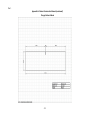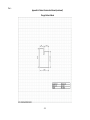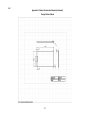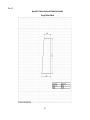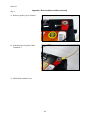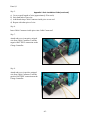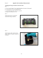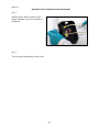
1
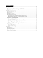
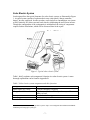
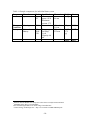
ESW House Electrification IDEA 398: Final Report IDEA 398 Winter 2008 Final Report Sarah Kornmeier Kari Nigorizawa Dan Pinkawa Fuko Tsuruta -1- Executive Summary Santo Domingo is a developing community located in Panama’s Chagres National Park, where there is no electric power grid and solar power is the only viable source of energy. Northwestern chapter of Engineers for a Sustainable World (ESW-NU) has been involved with development projects in the community for the past two years. Currently, there is a solar-powered charging station in the community, where community members can charge car batteries to provide electricity to their homes. Unfortunately, this system is inconvenient and provides the relatively few battery owners in the community with inconsistent electricity. The objective of the ESW House Electrification Project is to provide fourteen households in Santo Domingo with equal amounts of daily electricity while remaining within budget constraints. Our design must address issues related to equality among households, easy installation, operation, and maintenance, budget constraints, durability and reliability, upgradeability, safety, and environmental and social sustainability. In order to achieve these goals, we propose the implementation of solar electric systems. The proposed systems will support DC loads and require standard solar electric components including solar panels, charge controllers, and batteries. Santo Domingo’s ultimate goal is for each home to have its own solar electric system because individual solar electric systems will provide each home with the desired amount of electricity. With individual home systems, each household independently generates electricity and is responsible for the upkeep of the system. Independent systems are ideal but expensive to implement. If Santo Domingo is unable to secure sufficient funding for these systems, the community can implement charging stations, which require multiple houses to share a single solar panel. With our design, a charging station can provide two to four houses with electricity. As the number of houses supported by a charging station increases, the costs decrease, but the electricity provided to each home also decreases. The charging stations are designed to be upgradeable to individual home systems, if additional funding is available at a later date. A cabinet is necessary to protect the battery and charge controller and to ensure the safety of the users. The indoor cabinet is located inside each household and contains the battery and the charge controller. The outdoor cabinet is used at a charging station, and can be located either on the outside of a house or in a separate structure on which the solar panel is mounted. The future steps for Santo Domingo include securing funding and selecting and implementing the appropriate system type for the community. With the knowledge and experience gained through this project, ESW-NU will be able to improve conditions in numerous other developing communities around the world. -2- Table of Contents Executive Summary ............................................................................................................ 2 Introduction ......................................................................................................................... 4 The Community of Santo Domingo and ESW-NU ........................................................ 4 Objectives ....................................................................................................................... 4 Solar Electric System Design.............................................................................................. 6 Design Requirements ...................................................................................................... 6 Report Preview................................................................................................................ 6 Solar Electric System ...................................................................................................... 7 Individual Home Systems ............................................................................................... 8 Expected Electrical Loads for Individual Home System............................................. 8 Recommended Components for Individual Home System .......................................... 9 Alternatives: Charging Stations ................................................................................... 11 Concept of Charging Stations ................................................................................... 11 Solar Panel Mounting: Separate Structure vs. House ............................................... 13 Scheduling................................................................................................................. 13 Supported Electrical Loads for Alternatives ............................................................. 14 Recommended Electrical Components for Alternatives ........................................... 17 Cabinet Design .............................................................................................................. 18 Indoor Cabinet Design .............................................................................................. 18 Outdoor Cabinet Design ........................................................................................... 20 Next Steps ......................................................................................................................... 24 Planning Phase .............................................................................................................. 24 Implementation Phase ................................................................................................... 24 Future of Santo Domingo.............................................................................................. 24 Introduction The Community of Santo Domingo and ESW-NU Santo Domingo is a rural community in the Colón Province of Panama, where the Northwestern chapter of Engineers for a Sustainable World (ESW-NU) has been involved with community development projects. With a population of 70, the small town is situated in Chagres National Park near the Chagres River basin. The community supports itself by raising livestock and farming subsistence agriculture.1 ESW-NU has been involved in lifestyle improvement projects in the community for the past two years by installing solar panels to power ranch fences, the community church, and the local schoolhouse and its charging station. Solar power provides the only viable source of energy for the community since no nearby electricity grids exist. Currently, all electricity in Santo Domingo is generated by solar panels at five ranches, one 60-Watt and one 75-Watt solar panels at the schoolhouse, and one 60-Watt solar panel at the church.2 The centrally-located schoolhouse contains a charging station that will fully charge a car battery over approximately three days to be subsequently used for approximately 14 days. Four problems exist with this setup: 1) Only five households in Santo Domingo own batteries. 2) Most users must carry a heavy car battery over a half mile on foot from their houses to the school. 3) Batteries do not provide the homes with continuous power. 4) Batteries and wiring are left exposed inside the homes. Currently, Santo Domingo does not have the economic, organizational, or material resources to solve these problems. At this time, the community needs a solution that can provide reliable solar electricity to fourteen houses. Objectives The objective of the ESW House Electrification Project is to provide fourteen households in Santo Domingo with equal amounts of daily electricity while remaining within budget constraints. The ultimate goal is to provide each house with an independent solar electric system. We will present our designs to ESW-NU at the end of this quarter; they will begin implementation in the summer of 2008. ESW-NU is working with ACOCHA (Asociación Comunitaria Para el Manejo Participativo del Parque Chagres), a non-profit group in Panama, to find funding for the project. ACOCHA, acting on behalf of Santo Domingo, has found partial, conditional funding for the project. The Panamanian government agreed to match any outside funding that the community acquires up to an amount of $7,515.80. The total maximum funding available under this program is $15,031.60. (See Appendix A for a more 1 2 IDEA 298/398 - Team Solar Recharge (2006). Average Rancher Income, Wealth & Expenditures. Asthana, A et al. (2006). Final Report Panama Project. December 2006. -4- detailed explanation.) In order to address these financial limitations, we generated a range of options to implement if full funding is not obtained. -5- Solar Electric System Design Design Requirements Our design is intended for the people of Santo Domingo, as they are responsible for the operation, maintenance, and repair of the solar electric systems. The design must also be clearly understood by ESW-NU and ACOCHA because the members will be installing the first few systems in Santo Domingo. We need to consider the social, financial, environmental, and physical limitations of providing electricity to the fourteen households. The design must ensure that the system: - provides each household with an equal amount of electricity - is easy to install, operate, and maintain - remains within budget constraints - is durable and reliable - is upgradeable - is safe to operate and maintain within a household setting - minimizes environmental impact (environmental sustainability) - facilitates independent operation (social sustainability) Report Preview The goal of this report is to explain our project design. We will achieve this by first briefly describing the equipment needed to successfully meet the design requirements. Next, we will present the individual home system before offering some alternatives for system implementation. We will then explain our design of the cabinets which house the electrical components. Finally, we will show the steps ESW-NU and Santo Domingo need to take in the coming months in order to effectively implement the design. -6- Solar Electric System Our design utilizes the typical elements of a solar electric system, as illustrated in Figure 1. A typical system consists of a photovoltaic array (solar panel), charge controller, battery, inverter, and loads. In order to reduce costs and power consumption, our system will be limited to DC (direct current) loads, thereby eliminating the need for an inverter. Though the configuration of the components is standardized, the sizing of components requires further calculations, which will be discussed later in the report. Figure 1: Typical solar electric system3 Table 1 briefly explains each component’s function in a solar electric system. A more thorough explanation can be found in Appendix B. Table 1. Solar electric system components and their functions Component Photovoltaic (PV) Array Charge Controller Battery Load (Appliances) Function Converts sunlight to electricity Regulates current from PV array to battery and from battery to load Stores electrical energy Uses electricity to serve users 3 Sun, N. W. S. (March 16, 2008). Typical PV System <http://www.malignani.ud.it/WebEnis/NorthWindSouthSun/power/images/pvsystem.gif> -7- Individual Home Systems The ultimate goal of this project is to provide a solar electric system for each house. With individual home systems, each household independently generates electricity and is responsible for the upkeep of the system. Independent systems will provide each home with the desired amount of electrical power. However, this configuration is expensive to implement. If the community is unable to secure sufficient funding for individual home systems at this time, alternative options are described in the “Alternatives” section of this report. In this configuration, each house owns a solar panel, charge controller, battery, and DC loads (appliances). The components are configured in each household as shown in Figure 2. Solar panel Charge controller DC loads Battery Figure 2: Components of individual home systems Expected Electrical Loads for Individual Home System In order to design an appropriately sized system, our team accounted for the projected electrical loads per house. A base set of appliances and per-day usages were defined as the projected electrical load (see Table 2). This base set was determined from information collected directly from the user group in Santo Domingo during household surveys in December 2007 (see Appendix C for trip report section on appliances). -8- Table 2: Projected electrical loads per house Watts Description 5 5 5 5 2 12 LED Light LED Light LED Light LED Light Radio Black and white TV X Hrs/day = X 4 = X 4 = X 4 = X 4 = X 4 = X 4 = Total Wh/day Wh/day 20.0 20.0 20.0 20.0 8.0 48.0 136.0 The projected electrical load is derived from four LED lights, a radio, and a 12-inch DC TV each running for four hours per day. The energy consumption is 136 Watt-hours per day and represents the maximum expected load. Other appliances may be used and runtimes may vary provided that total daily appliance use does not exceed 136 Watthours. For a more detailed explanation of the calculation method, see Appendix D. We recommend LED lights because compared to traditional incandescent lights or CFLs (compact fluorescent lights), they have longer life spans and better power efficiencies. In addition, LED lights can be disposed of safely. If LED lights are not available in Santo Domingo, the four 5-W LED light bulbs can be substituted by two 16-Watt CFL bulbs which can be supported by the system for 3.1 hours each per day. See Appendix E for a more detailed comparison among LED lights, incandescent lights, and CFLs. Recommended Components for Individual Home System To operate the above appliances, each individual home system needs electrical components with the following specifications (see Table 3). See Appendix C for detailed calculations. Table 3: Component specifications for individual home system Component Photovoltaic (PV) Array Charge Controller Battery Appliances Recommended Specifications Wattage: 60 Watts Operating current: 3.4 Amps, or at least that of PV array Capacity: 42 Ah 12V DC Table 4 contains examples of electrical components that satisfy the specifications above. The prices and availability of these components in Santo Domingo have not been confirmed. Components with capacities close to the recommended specifications will allow for a more efficient system. -9- Table 4: Example components for individual home system Component Manufacturer Model KCSolar Panel Kyocera 65T Charge Controller Battery Morningstar SHS-6 Universal Battery UB22NF GEL Specifications Maximum power: 65 W Maximum current: 3.75 Current: 6 A Battery type: Gel Deep Cycle Capacity: 60 Ah 4 Dimensions Weight 751 x 652 x 6.0 kg 46 mm Cost $4124 15.1 x 6.6 x 3.6 cm 238 x 140 x 235 mm 113 g $495 38.5 lb (17.5 kg) $1746 Total: $635 Northern Arizona Wind & Sun <http://store.solar-electric.com/kykc65wasomo.html> Affordable Solar <http://www.affordablesolar.com/Morningstar.SHS.6.12V.Solar.Charge.Controller.htm> 6 Creative Energy Technologies Inc. < http://www.cetsolar.com/PDF/UB22NF.pdf> 5 - 10 - Alternatives: Charging Stations In order to accommodate the uncertainty of the available funding for this project, we have designed charging stations, which are lower-cost alternatives to the individual home system. The charging stations can provide two to four houses with electricity. As the number of houses supported by a charging station increases, the cost decreases, the electrical capacity decreases, and the walking time increases (see Table 5). Table 5: Summary of trade-offs among alternatives Tradeoffs Individual home system $635 136 Wh 2-house system $583 86 Wh 3-house system $488 58 Wh 4-house system $440 43 Wh Cost per house* Electrical capacity 0 min 2 min 4 min 5 min Walking Time * Costs only include solar panel, charge controller, and battery, and exclude appliances, wires, and materials for installation. Not only do these alternatives provide flexibility for the community, but they can also act as a means for Santo Domingo to appeal for more funds. The community will be able to show that with less funding, they sacrifice availability of electricity and convenience. The “Supported Electrical Loads for Alternatives” section will describe in detail the available electricity for these alternatives. Concept of Charging Stations Charging stations require multiple houses to share a single solar panel. They are less expensive than individual home systems because they reduce the required number of solar panels, the most costly component of the solar electric system. For this project, a charging station would consist of a solar panel and a charge controller. The solar panel will be mounted on either an existing house or a separate structure. Each house will own a battery, a charge controller, and appliances. The battery will be transported between the house and the charging station, while the charge controller will remain at the house. We generated three alternatives to the individual home system. They are the 2-house system, the 3-house system, and the 4-house system. The nomenclature indicates the number of houses sharing a solar panel (see Figure 3-Figure 5.) Figure 3: 2-house system - 11 - Figure 4: 3-house system Figure 5: 4-house system Santo Domingo will need to group the houses based on the most appropriate social and geographical configuration. For example, households consisting of relatives may want to share a system. On the other hand, the households need to be in the proximity of a charging station to reduce walking distances. In the 3- and 4-house systems, the fourteen houses do not divide evenly into groups of three and four. In these cases, the extra houses will form their own group. Figure 6 shows a detailed view of the 3-house system; each house owns a battery, a charge controller, and appliances. The spare battery and charge controller will be discussed subsequently. - 12 - Spare battery and charge controller Figure 6: Detailed View of a 3-House System Solar Panel Mounting: Separate Structure vs. House The solar panel for a charging station can be mounted on either an existing house or a separate structure. Although an independent structure entails additional material and labor costs, it may present fewer social problems. Charging stations, whether they are separate structures or located at a house, may present social conflicts concerning ownership, upkeep responsibility, and walking distances. One house may become solely responsible for the maintenance of the charging station, especially if it is located on this house. If charging stations are located closer to one household, the other households may resent the extra walking. On the other hand, it may cause discomfort to those living in the house due to reduced privacy. A house with a charging station may choose to directly connect their household system to the panel, gaining an unfair advantage over the other households. If a household charges a battery out of sequence on the charging station schedule (see next section), other households would lose their ability to have daily electricity. Should these issues arise, they will be resolved appropriately by ACOCHA and Santo Domingo. Scheduling When multiple users charge their respective batteries at a single location, the issue of scheduling arises. Since two, three, or four households cannot charge their batteries simultaneously, there must be an equitable and efficient method to address this issue. To - 13 - provide electricity to a household while its battery is being charged, we recommend the use of a spare battery. Thus houses can have electricity even after they have just left the discharged battery at the charging station. Below are schedules which alternate charging times among batteries (see Table 6-Table 8). Table 6: Proposed charging schedule for 2-house system Days: 1 2 3 4 5 6 7 8 9 10 11 12 13 14 15 16 17 18 19 20 21 22 23 24 Battery 1 Charge Battery 2 Hs 1 Disch. Battery 3 House 1 Discharge Charge Charge House 2 Discharge House 2 Discharge House 2 Discharge Charge Charge Hs 1 Disch. House 1 Discharge Charge Table 7: Proposed charging schedule for 3-house system Days: 1 2 3 4 5 6 7 8 9 10 11 12 13 14 15 16 17 18 19 20 21 22 23 24 Battery 1 Charge House 1 Discharge Battery 2 Hs 1 Dis. Charge House 2 Discharge Battery 3 House 2 Discharge Charge Battery 4 Charge House 3 Discharge House 2 Discharge Charge House 3 Discharge House 3 Discharge Charge Charge Hs 1 Dis. House 1 Discharge Charge Table 8: Proposed charging schedule for 4-house system Days: 1 2 3 4 5 6 7 8 9 10 11 12 13 14 15 16 17 18 19 20 21 22 23 24 House 1 Charge House 1 Discharge House 2 Hs 1 Dis. Charge House 3 House 2 Discharge Charge House 4 House 3 Discharge Spare Charge House 2 Discharge House 2 Discharge Charge Hs 3 Dis. House 3 Discharge Charge House 4 Discharge Charge House 4 Discharge Charge House 1 Discharge Supported Electrical Loads for Alternatives The calculation of the electrical loads was based on the battery weight and charging rate. The limiting factor in the electrical load calculation for the alternatives is the weight of the battery. We determined that a person could carry a maximum weight of 50 pounds - 14 - between the house and the charging station.7 This weight restriction limits the battery capacity to approximately 72 amp-hours. Using the conventional charging rate of “C/20,” the capacity limitation significantly reduces the charging rate, which in turn lengthens the charging time. The C/20 charging rate means that for maximum efficiency, a battery with a “C”-amp-hour capacity can charge at a current of C/20 amps. A 72-amp-hour battery can charge at 3.6 amps. C 72 Ch arg ing current 3.6 A 20 20 Since the charging time is the capacity divided by the charging rate, a battery of any size takes 20 hours to fully charge from 0% to 100% according to the C/20 charging rate. C Ch arg ing time 20 hr C 20 In the case of charging stations, the household cannot use the battery’s full capacity. This is because with a charging time of 20 hours and 4 sun hours per day in Panama (see Appendix F for explanation of sun hours), the charging time for the battery is 5 days. Therefore, there is not sufficient time in the schedule to fully recharge the battery if a household discharges the battery completely. Although the household can only use a portion of the battery’s capacity, the capacity itself cannot be reduced because the charging rate would also be reduced, which in turn lengthens charging time. The battery’s depth of discharge (the amount of electricity that can be used before the battery needs to be recharged) varies for each alternative. It is the greatest for the 2-house system and decreases as more houses are added. In other words, the 2-house system allows a household to use the largest portion of the actual battery capacity compared to the other alternatives, and therefore permits the highest allowable electrical load per house. Table 9 shows the supported electrical loads for the individual home system and the three alternatives, with corresponding appliance usage. Table 9: Supported electrical loads for all system designs Electrical capacity for each household Possible appliances and hours of use per day 7 Individual home system 2-house system 3-house system 4-house system 136 Wh/day 86 Wh/day 58 Wh/day 43 Wh/day 4 x 5W lights 2 x 5W lights 2 x 5W lights 2 x 5W lights for 4 hours for 3.9 hours for 2.6 hours for 4.3 hours 1 x 2W radio 1 x 12W TV 1 x 12W TV for 4 hours for 3.9 hours for 2.6 hours 1 x 12W TV for 4 hours Ergonomic Lift Guide. <http://www.ohiobwc.com/employer/programs/safety/Ergoliftguide.asp> - 15 - Although it provides the highest amount of electricity, the 2-house system is the most expensive of all the charging station alternatives. This is because the total number of solar panels, charge controllers, and batteries used by the community is the highest for this alternative. There is one solar panel for every two houses instead of every three or four houses. Additionally, there needs to be a spare battery and a spare charge controller for every two houses (instead of every three or four) to provide daily electricity to each household. The variation in the number of electrical components and its effect on cost are shown in Table 10. Table 10: Costs and number of components for all system designs Individual home system 14 solar panels 14 charge controllers 14 batteries 2-house system 3-house system 4-house system 7 solar panels 5 solar panels 4 solar panels Total 21 charge 19 charge 18 charge number of controllers controllers controllers components 21 batteries 19 batteries 18 batteries for all 14 houses $8,890 $8,155 $6,829 $6,166 Total cost* Cost per $635 $583 $488 $440 house* * Costs do not include appliances, wires, or materials for installation. We designed for a standardized set of components for the alternatives (2- to 4-house systems), which makes the system both flexible and upgradeable. The battery, charge controller, and solar panel specifications are the same for all charging station alternatives. Thus, it is relatively easy to move from one lower-cost alternative to a higher-cost alternative (when additional funding is acquired) by purchasing additional components of the same specifications. Furthermore, the components recommended for the alternatives have a slightly higher capacity than that for the individual home system. This allows for a smooth transition from any alternative to the preferred configuration, the individual home system (see Table 11). The difference in the component specifications comes from the driving factor of design calculations (expected loads for individual home systems and battery weight limit for shared systems) and the component setup (battery connected continuously for individual home systems and batteries switched for shared systems). See Appendix G for complete load and specification calculations for charging station alternatives. Table 11: Component specifications for all system designs Components Solar panel Charge controller Battery Individual home system 60 W 3.4 A 43 Ah - 16 - Shared system (2- to 4-house system) 63 W 3.6 A 72 Ah Recommended Electrical Components for Alternatives Table 12 contains examples of electrical components that satisfy the specifications above for charging station systems. The prices and availability of these components in Santo Domingo have not been confirmed. Components with capacities close to the recommended specifications will allow for a more efficient system. Table 12: Example components for charging station system (per house) Component Manufacturer Model Specifications Dimensions KCMaximum 751 x 652 x Solar Panel Kyocera 65T power: 65 W 46 mm Maximum current: 3.75 Morningstar SHS-6 Current: 6 A 15.1 x 6.6 x Charge 3.6 cm Controller Universal UB-24 Battery type: 276 x 171 x Battery Battery GEL Gel Deep 251 mm Cycle Capacity: 75 Ah at 20-hr rate 8 Weight Cost 6.0 kg $4128 113 g $499 53.5 lb (24.3 kg) $20210 Total: Varies by alternative (see Table 10) Northern Arizona Wind & Sun <http://store.solar-electric.com/kykc65wasomo.html> Affordable Solar <http://www.affordablesolar.com/Morningstar.SHS.6.12V.Solar.Charge.Controller.htm> 10 Creative Energy Technologies Inc. < http://www.cetsolar.com/PDF/UB24.pdf> 9 - 17 - Cabinet Design A cabinet is necessary to protect the battery and charge controller from the elements in order to maintain their durability and reliability, and to ensure the safety of the users. We have designed two types of cabinets: indoor and outdoor. For instructions on building these cabinets, see Appendix H. Indoor Cabinet Design The indoor cabinet is located inside each household and contains the battery and charge controller. The indoor cabinet has four main design features (see Figure 7-Figure 8): 1. hip-height battery box 2. anti-tipping protruding base 3. child-proof sliding door 4. opening for wiring 3. Child-proof sliding door 1. Hip-height battery box 2. Anti-tipping protruding base Figure 7: Indoor cabinet 4. Opening for wiring Figure 8: Indoor cabinet (exploded view) - 18 - The height of the battery box is set to 93 cm to maximize the ease of lifting and placing the 50-pound battery. For an average person of 176 cm, the height of the cabinet corresponds to a height slightly below the hip to minimize the distance between lifting/placing position and carrying position of the battery. Since the heavy battery is located at the top, the center of mass of the cabinet is high, making it prone to tipping. We designed the base of the indoor cabinet to be 10 cm deeper than the top to prevent tipping. The most likely direction of tipping is to the front, since the depth is shorter than the width of the cabinet. Tipping to the front is dangerous because the contents of the cabinet, including the heavy battery, may fall out. A small child in front of a tipping cabinet may be severely injured. The protruding base will ensure that the mass of the cabinet will have to be lifted over a longer arc before tipping (see Figure 9). Point of rotation Point of rotation Figure 9: Arc path of battery for straight base and protruded base The door of the battery box is designed to slide upward to lessen the risk of child tampering. Because the handle of the door is at the top, it is out of reach of a small child. Even a taller child who can reach the handle would need to lift the door still higher to open it wide enough to access the contents of the battery box. When an adult needs to access the battery and charge controller, the sliding door can be removed and placed either on top of or beside the cabinet. Wiring is made accessible through a hole at the top right corner of the back of the battery box (see Figure 8). The wires run from a connector (that connects to the battery) to the - 19 - charge controller located inside the cabinet, through the hole, to a T-connector (for multiple appliance use) outside the cabinet, and finally to the appliances. This wiring will be clipped to the inner walls of the box so it will not interfere with the removing and replacement of the battery. The charge controller will be attached to the interior right wall of the battery box using screws (see Figure 10). A wire connector is necessary inside the cabinet only if the household is using a charging station, which requires frequent disconnecting and reconnecting of the battery to the charge controller. In this case, we recommend the use of a battery charging cable connector (see Figure 11), which will only connect to its match that runs to the charge controller. Figure 10: Battery and charge controller inside battery box Figure 11: Example of battery charging cable connector11 Outdoor Cabinet Design The outdoor cabinet will be used at the charging station. It provides the user with an accessible outside space to charge the battery. It can be located either on the outside of a house or in a separate structure on which the solar panel is mounted. A charge controller is permanently connected to the solar panel and attached to either the outside of the house or the separate structure, directly above the cabinet. The user charging the battery will follow these steps: 1. Place the empty battery in the empty compartment. 2. Unlock the hinged door. 3. Disconnect the charge controller from the charged battery and reconnect it to the empty battery. 11 McMaster-Carr: Battery Charging Cable Connectors, North American Style Connectors. <http://www.mcmaster.com/> - 20 - 4. Swing the door to close the compartment housing the empty battery. 5. Take the charged battery back to the user’s house. See Figure 12 for a schematic of the battery-switching process. Figure 12: Schematic of switching batteries at charging station The outdoor cabinet has six main design features (see Figure 13-Figure 14). 1. hip-height battery box 2. anti-tipping protruded base 3. two compartments 4. hinged door 5. opening for wiring 6. lock for security from vandalism - 21 - 3. Two compartments 1. Hip-height battery box 4. Hinged door 2. Anti-tipping protruding base Figure 13: Outdoor cabinet 5. Opening for wiring 6. Lock for security from vandalism Figure 14: Outdoor cabinet (transparent top) The outdoor cabinet has similarities to the indoor cabinet. The height of the battery box is slightly below hip height to facilitate easy lifting and placing of the battery. Easy access to the battery box is important because this will be the first opportunity for the user to set the battery down after carrying it on foot from the house. The outdoor cabinet also features an anti-tipping protruded base, similar to the indoor cabinet. The outdoor cabinet design has two compartments that further facilitate quick battery replacement and retrieval. The user at the charging station needs a site to place the battery just carried from the user’s house, so that the user can remove the other, fully-charged, battery to transport back to the house. We have solved this problem by creating an empty compartment beside the occupied compartment. This provides a stable place for the user to set the empty battery while the door to the charged battery compartment is being unlocked. - 22 - The single hinged door allows the user to place the battery without opening the door first, and to remove the battery without having to close the door afterward. The user will unlock the hinged door after placing the empty battery in the empty compartment. After closing the door on this compartment, the user can lock it before lifting the charged battery to carry back home. There is no need to open or close the door while holding a battery. We designed a path for the wire through the battery box that allows for easy connecting and reconnecting of batteries to the charge controller, while still preventing invasion by the elements. Incoming wire from the charge controller enters the battery box through its backside to prevent any debris or rain from infiltrating the battery box and damaging the battery. These wires terminate in a connector that only connects to the battery through the charge controller, similar to that used in the indoor cabinet. There is also an “L”shaped slit in the slab dividing the two compartments. This opening allows the connector at the end of the wires to swing back and forth between the two compartments. After the user places the discharged battery in the empty compartment, the user will open the door to the charged battery’s compartment. The user will then unhook the battery box’s connector from the charged battery’s matching connector, push the box’s connector through the slit to the other compartment, connect it to the empty battery’s charge controller, and close the door to this compartment. In order to protect the charge controller and battery from vandalism, the battery box will be secured by either a combination lock or a padlock on the door handle. Each house that is sharing a particular charging station will have the combination number or the key to the lock. We suggest the community’s solar committee remain in possession of all combination numbers or a master key that can unlock all charging station cabinets. - 23 - Next Steps Planning Phase Santo Domingo’s first step toward implementing this project is to secure funding, as the selection of an implementation option is dependent on this available funding. After sufficient funding is acquired, Santo Domingo, with the aid of ACOCHA, will choose an alternative the community can afford with the available funds. Upon choosing a system, whether it is the individual home system or one of the charging station alternatives, the community will acquire components that satisfy the recommended specifications. Implementation Phase In the summer of 2008, ESW-NU will assist Santo Domingo with the construction and installation of the solar electrification system. We developed a basic installation guide that will guide them through the setup (see Appendix I). We also recommend a published manual for more extensive information on the installation, operation, and maintenance of solar electrification systems (see Appendix J). ESW-NU will also have access to our online file depot and team management system for information beyond the scope of this report (see Appendix K). Future of Santo Domingo After ESW-NU initiates the implementation of these systems in Santo Domingo, ACOCHA will be left as the organization responsible for continuation of the project in the community. As ESW-NU proceeds onto other sustainability-related projects, its members will utilize our design concepts and this experience with Santo Domingo to improve conditions in numerous other developing communities around the world. - 24 - APPENDICES: Outline of Appendices The following are the appendices referenced to in the final report: A. B. C. D. E. F. G. H. I. J. The funding section of ESW-NU’s final December 2007 trip report Thorough explanation of each component’ function A Summary of Information Collected Through Surveys in December 2007 Calculation method for calculating electric load per house, individual Comparison of LED lights, Incandescents, and CFL’s Definition of sunlight hours and sun-hour chart Detailed calculations on recommended components for alternatives Cabinet Construction Manual Basic Installation Guide Recommended manuals for installation, operation and maintenance of solar electric system -25- APPENDIX A: Funding Section of ESW NU’s December Trip Report The following is a section from ESW NU’S December 2007 Trip Report; the document has been underlined to highlight certain points1. 3.2 ACOCHA ACOCHA is an organization of members of the communities in the National Park. The acronym stands for “Asociacin Comunitaria Para el Manejo Participativo del Parque Chagres,” and their slogan is “Promoviendo la protecci n de los Recursos Naturales con la participati n y beneficio de su Gente.” It was officially recognized as an organization about a year ago. They were founded by SONDEAR (Sociedad Nacional para el Desarrollo de Empresas y `reas Rurales) so that members of the communities can have input in what goes on in their communities. During [ESW-NU’s] meeting with the president and other representatives of ACOCHA, they clarified their purpose in dealing with the communities. The president, Paulino Flores, stated that at no time did they [ACOCHA] promise money for the house electrification project in Santo Domingo. They are an organization devoted to helping communities find funding and they act as a liaison between communities and other organizations which can provide funding, but ACOCHA does not have funding itself. Initially, ACOCHA had only asked if [ESW-NU] had the funding to support one half of the project since a government representative had promised to provide the other half (they gave us a copy of the letter promising a total of $7,515.80). [ESW-Nu] explained several times that [they] were not an organization to provide funds but rather a designing and technical organization. [ESW-NU] made it clear that [they] could only provide $1000 for tools or maintenance of the system but that [they] could not provide funds for the project itself. [ACOCHA] have asked a few other organizations for funding but have been denied or have received no reply at all. In the end, [ESW-NU] stated that [they] could not fund this project but that [they] could help them with writing grants and searching for other ways of funding the project. Also, if they found funding [ESW-NU] could serve as designers or technical support and in return they can provide [ESW-NU] with information about the communities, transportation to communities within the park, and contact with other organizations… 1 Fan, W., Yu, S., Vega, C., & Summersgill, B. (2007). Panama Winter 2007 Final Report Draft: Northwestern University. -26- APPENDIX B: Detailed Explanation of Solar System Components Photovoltaic (PV) sources convert energy from the sun, a sustainable source of energy, into electrical energy. The direct current (DC) produced by the PV panel flows into a charge controller, which regulates its distribution to the other components of the system2. The charge controller is also responsible for ensuring that the battery is charged at an optimal rate and that too much charge is neither added nor removed from the battery. If the load (electrical appliance) runs on alternating current (AC), then an inverter is needed to convert the current from DC to AC3. The minimal number of components, in addition to the relatively reliable and easy maintenance of the system, makes solar systems a popular choice for rural communities off the electricity grid. Solar Panel Solar panels are made of solar cells usually consisting of precisely fabricated semiconductor films. When light excites electrons over the p-n junction, a flow of DC current arises, see Figure 1. Figure 1: Diagram of Solar Cell4 2 For an animated version of a solar system, see www.sundaya.com 3 For more information, please see document in the Depot Folders labeled Research/Component Research and Research/ Solar Electric System Information. 4 Sproul, A. (2005). Lecture 3 The Behavior of Solar Cells. On Lectures on Applied Photovoltaics: University of New South Wales Centre for Photovoltaic Engineering. -27- Charge Controller Charge controllers manage and control a solar system. Charge controllers regulate the current and voltage coming from the solar panels and entering the battery. This is important since a 12 V panel can output at up to 20 V; this would damage the battery if it were directly connected to the solar panels. They also control backwards current flow into the solar panel, which would result in expensive damage. There are three types of charge controllers, their amperage can vary anywhere from 6-40 Amps. The first type is a 1 or 2-stage contol that is relatively simplistic. The second type, the type suggested for Santo Domingo is a 3-stage or Pulse Width Modulation (PWM) charge controller. This type of controller sends a series of short pulses to the battery to check its state of charge. They are regarded as the industry standard of controllers and their costs are reasonable. The third type is a maximum power power tracking controller (MPPT). MPPT’s are expensive and only necessary for large systems, so they are not a viable option for this project. Leading charge controller manufacturers include: Morningstar, Xantrex and Steca. Battery Battery is a device consisting of one or more electrically connected electrochemical cells, which is designed to receive, store, and deliver electric energy. In practice, battery capacity is commonly expressed in ampere-hours (Ah) or Milli-ampere-hours (MAh). The total energy in a battery is its capacity multiplied by its voltage (P*t = I*t*V) which results in a measurement of watthours.5 Practically all batteries used in PV and all but the smallest backup systems are Lead-Acid type batteries. These include the standard flooded (wet) batteries, gelled, and AGM. The lifetimes for these batteries are 3-12 months for starting (car) batteries, 4-7 years for AGM deep cycle batteries, and 2-5 years for gelled deep cycle batteries.6 Although deep cycle batteries are generally more expensive than starting batteries, we recommend deep cycle batteries because of their long lifespan and their intended use in PV systems. 5 <http://www.extremetech.com/article2/0,1697,1155267,00.asp> 6 <http://www.electronsolarenergy.com/education_batteries_1.htm> -28- Inverter (note: there are no inverters in our systems) Inverters are necessary in applications with AC loads. An inverter would convert the DC current leaving the charge controller into AC. This conversion occurs when entering DC current passes through a transformer in the inverter, than the current can take two paths to the same exit, producing an alternating current at the exit point. Most inverters produce square waves and these inverters are called modified-sine wave inverters. They are inexpensive and produce a wave-form that can run most devices. Our team recommends that households purchase modified-sine wave inverters if they want to run AC loads. The other type of inverter is called truesine wave. It produces wave-forms that resemble a sine wave. This more expensive inverter variety is needed for applications where appliances that need time or temperature controls. Leading inverter manufacturers include: Kyocera and Xantrex. -29- Appendix C: A Summary of Information Collected Through Surveys in December 2007 Twelve houses were surveyed by ESW members on the December 2007 trip. The surveys were meant to average household’s desired loads and the following table summarizes the results7. Table 1C: Summary of Load Survey Load Total number Estimated hours Estimates power desired over all used per day consumption per 12 houses hour TV 11 3.25 12 W Lights 31 2.3 -Radio 1 --Cell Phone 4 --Charger Oven 1 --Iron 1 --Microwave 1 --The seven houses that owned batteries also filled out another part of the survey. The following table summarizes that information Table 2C: Summary of Battery Survey Average number of 1 batteries per house Average months of 11 ownership Days between charges 13.2 7 This table was adapted from survey2003.xls located on depot: /Component and System Sizing -30- Appendix D: Calculation of Loads per House and Component Specifications in Individual Home Systems The table below shows the calculation method used to determine the expected loads per house and the component specifications that can support these loads. Individual home system: each house has a solar panel, a charge controller, a battery, and the following appliances. LOAD Line DC loads CALCULATION item Description Watts X Hrs/day = Light 5 X 4 = Light 5 X 4 = Light 5 X 4 = Light 5 X 4 = Radio 2 X 4 = Black and white TV 12 X 4 = 1. Total Wh/day 2. DC system voltage. 3. Divide line 1 by line 2. This is total amp-hours per day used by DC loads. Wh/day 20.0 20.0 20.0 20.0 8.0 48.0 136.0 12.0 11.3 (Wh/day) (V) (Ah/day) SOLAR PANEL SIZING 1. 2. 3. 4. 5. Total average Ah/day from the LOAD CALCULATION. Multiply line 1 by 1.2 to compensate for loss from battery charge/discharge. Average sun hours per day. Divide line 2 by line 3. This is the total solar array amps required. Corresponding wattage of solar module (from solar module specs). 11.3 13.6 4.0 3.40 59.5 (Ah/day) (Ah/day) (Hours) (Amps) (Watts) BATTERY SIZING 1. 2. 3. 4. Total average Ah/day from the LOAD CALCULATION. Maximum number of continuous cloudy days expected in area. Multiply line 1 by line 2. Divide line 3 by (maximum) 0.8 to maintain a 20% reserve after deep discharge period. This is the optimum battery size in amp-hours. 11.3 3.0 34.0 42.5 (Ah/day) (days) (Ah) (Ah) -31- Appendix E: Comparison of LED Lights, Incandescent Lights and Compact Fluorescent Lights8 Incandescent Lamps Requires most power, least efficient Do not require a ballast Compact light source Simple maintenance due to screw-in Edison base Shorter service life Filament is sensitive to vibrations and jarring Bulb can get very hot during operation, energy lost as heat Must be properly shielded because incandescent lamps can produce direct glare as a point source Require proper line voltage as line voltage variations can severely affect light output and service life Fluorescent Lamps (CFL’s) Require a compatible ballast Low surface brightness compared to point sources Cooler operation, less energy lost as heat as compared to incandescent Ambient temperatures and convection currents can affect light output and life All fixtures installed indoors must use a Class P ballast that disconnects the ballast in the event it begins to overheat; high ballast operating temperatures can shorten ballast life Options for starting methods and lamp current loadings Low temperatures can affect starting Long product life (30,000 hour lifetime) Frequent on and off can damage bulb Immediate failure LED Lights Do not require a ballast Range of color temperatures, do not change with voltage Coolest operation Run better on Ac that DC Short circuits can occur from high temperatures Longest product life (35,000 to 50,000 hour lifetime) Frequent on and off does not damage bulb Dims over time instead of immediate failure More expensive than CFL’s and incandescent 8 For more information about LED lights see depot folder Reseach/Load Research -32- Appendix F: Definition of sun-hours and average sun-hours for Panama “Sun-hours” are a measure of solar insolation in kilowatt-hours per square meter per day. For simplicity, this figure is often called "sun-hours/day." The table below shows the monthly average peak sun-hours (PSH) for Panama.9 These are the equivalent number of hours per day when solar irradiance averages 1 kW/m2 10 .We designed for the minimum value of 4 PSH, which occurs in June and October, so that the system is functional all year. Jan Feb March April May June July August September October November December 9 4.94 5.56 5.61 5.03 4.44 4 4.19 4.28 4.28 4 5.11 4.42 Joe Phillip, ESW Solar Advisor. 10 Darling, D. Peak Sun Hours. from http://www.daviddarling.info/encyclopedia/P/AE_peak_sun_hours.html -33- Appendix G: Method for Calculating Loads per House and Component Specifications in Charging Station Alternatives The tables below shows the calculation method used to determine the supported loads per house and the component specifications with battery capacity of 72 Ah as the driving force. Table G1: Calculation method for 2-house system 2-house system: each house has a charge controller, a battery, and the following appliances. A solar panel, a spare battery, and a spare charge controller are shared by two households. LOAD Line DC loads CALCULATION item Description Watts X Hrs/day = Light 5 X 3.93 = Light 5 X 3.93 = Light 0 X 0 = Light 0 X 0 = Radio 0 X 0 = Black and white TV 12 X 3.93 = 1. Total Wh/day for houses supported by one charging station 2. Inverter DC input voltage - this is DC system voltage. 3. Divide line 1 by line 2. This is total amp-hours per day used by DC loads. Wh/day 19.6 19.6 0.0 0.0 0.0 47.1 86.4 12.0 7.2 (Wh/day) (V) (Ah/day) 7.2 (Ah/day) 8.0 57.6 72.0 (days) (Ah) (Ah) 72.0 3.6 (Ah) (Amp) 1.0 3.60 63.0 3.6 3.6 4.0 14.4 4.00 (Amp) (Watt) (Amp) (Amp) (Hours) (Ah/day) (days) Limitations on charging time: how fast solar panel can send current and how fast battery can recharge. CHARGING TIME BATTERY SIZING SOLAR PANEL SIZING 1. From LOAD CALCULATION, the total amp-hours used by each household per day. 2. How many days the battery should last for each household. 3. The amp-hours required by each household per discharge period. 4. Divide line 2 by (maximum) 0.8 to maintain a 20% reserve after deep discharge period. This is the optimum battery size in amp-hours. 5. Select battery with the above amp-hour capacity. 6. Divide line 5 by 20. This is the most efficient current for charging the battery. The solar panel current output is preferably smaller this amount. 7. Number of solar panels in parallel. 8. Divide line 6 by line 7. The limiting output current for each solar panel. 9. Wattage and amperage of solar panel with output current below amount in line 8: determine from specs. 10. Multiply amperage from line 9 by line 7. Total output current for all solar panels. 11. Average sun hours per day. 12. Multiply line 10 by line 11. Total amp-hour output from solar panels per day. 13. Divide line 3 by line 12. The total charging time for each battery. -34- Appendix G: Method for Calculating Loads per House and Component Specifications in Charging Station Alternatives (continued) Table G2: Calculation method for 3-house system 3-house system: each house has a charge controller, a battery, and the following appliances. A solar panel, a spare battery, and a spare charge controller are shared by three households. LOAD Line DC loads CALCULATION item Description Watts X Hrs/day = Light 5 X 2.62 = Light 5 X 2.62 = Light 0 X 0 = Light 0 X 0 = Radio 0 X 0 = Black and white TV 12 X 2.62 = 1. Total Wh/day for houses supported by one charging station 2. Inverter DC input voltage - this is DC system voltage. 3. Divide line 1 by line 2. This is total amp-hours per day used by DC loads. Wh/day 13.1 13.1 0.0 0.0 0.0 31.4 57.6 12.0 4.8 (Wh/day) (V) (Ah/day) 4.8 (Ah/day) 9.0 43.2 54.0 (days) (Ah) (Ah) 72.0 3.6 (Ah) (Amp) 1.0 3.60 63.0 3.60 3.6 4.0 14.4 3.00 (Amp) (Watt) (Amp) (Amp) (Hours) (Ah/day) (days) Limitations on charging time: how fast solar panel can send current and how fast battery can recharge. CHARGING TIME BATTERY SIZING SOLAR PANEL SIZING 1. From LOAD CALCULATION, the total amp-hours used by each household per day. 2. How many days the battery should last for each household. 3. The amp-hours required by each household per discharge period. 4. Divide line 2 by (maximum) 0.8 to maintain a 20% reserve after deep discharge period. This is the optimum battery size in amp-hours. 5. Select battery with the above amp-hour capacity. 6. Divide line 5 by 20. This is the most efficient current for charging the battery. The solar panel current output is preferably smaller this amount. 7. Number of solar panels in parallel. 8. Divide line 6 by line 7. The limiting output current for each solar panel. 9. Wattage and amperage of solar panel with output current below amount in line 8: determine from specs. 10. Multiply amperage from line 9 by line 7. Total output current for all solar panels. 11. Average sun hours per day. 12. Multiply line 10 by line 11. Total amp-hour output from solar panels per day. 13. Divide line 3 by line 12. The total charging time for each battery. -35- Appendix G: Method for Calculating Loads per House and Component Specifications in Charging Station Alternatives (continued) Table G3: Calculation method for 3-house system 4-house system: each house has a charge controller, a battery, and the following appliances. A solar panel, a spare battery, and a spare charge controller are shared by four households. LOAD Line DC loads CALCULATION item Description Watts X Hrs/day = Light 5 X 4.32 = Light 5 X 4.32 = Light 0 X 0 = Light 0 X 0 = Radio 0 X 0 = Black and white TV 0 X 0 = 1. Total Wh/day for houses supported by one charging station 2. Inverter DC input voltage - this is DC system voltage. 3. Divide line 1 by line 2. This is total amp-hours per day used by DC loads. Wh/day 21.6 21.6 0.0 0.0 0.0 0.0 43.2 12.0 3.6 (Wh/day) (V) (Ah/day) 3.6 (Ah/day) 12.0 43.2 54.0 (days) (Ah) (Ah) 72.0 3.6 (Ah) (Amp) 1.0 3.60 63.0 3.60 3.6 4.0 14.4 3.00 (Amp) (Watt) (Amp) (Amp) (Hours) (Ah/day) (days) Limitations on charging time: how fast solar panel can send current and how fast battery can recharge. CHARGING TIME BATTERY SIZING SOLAR PANEL SIZING 1. From LOAD CALCULATION, the total amp-hours used by each household per day. 2. How many days the battery should last for each household. 3. The amp-hours required by each household per discharge period. 4. Divide line 2 by (maximum) 0.8 to maintain a 20% reserve after deep discharge period. This is the optimum battery size in amp-hours. 5. Select battery with the above amp-hour capacity. 6. Divide line 5 by 20. This is the most efficient current for charging the battery. The solar panel current output is preferably smaller this amount. 7. Number of solar panels in parallel. 8. Divide line 6 by line 7. The limiting output current for each solar panel. 9. Wattage and amperage of solar panel with output current below amount in line 8: determine from specs. 10. Multiply amperage from line 9 by line 7. Total output current for all solar panels. 11. Average sun hours per day. 12. Multiply line 10 by line 11. Total amp-hour output from solar panels per day. 13. Divide line 3 by line 12. The total charging time for each battery. -36- Appendix H: Cabinet Construction Manual The following pages cover the necessary tools and materials and the configuration of the parts for the cabinet. The actual methods used to join the pieces are left up to the community members. ----------------------------------------------------------------------------------------------------------For this project you will be building: Indoor Cabinet Charge Station Cabinet -37- Appendix H: Cabinet Construction Manual (continued) Tools NOTE: ALL UNITS ARE IN MILLIMETERS For this project you will need: Saw Hammer Flat-head screwdriver Philips-head screwdriver Ruler -38- Appendix H: Cabinet Construction Manual (continued) Indoor Cabinet 1 2 3 5 4 6 8 7 9 10 Part Number Part Name Page Number 1 Cabinet Left Side 4 2 Cabinet Top 5 3 Cabinet Rear 6 4 Cabinet Right Side 7 5 Cabinet Door 8 6 Cabinet Bottom 9 7,9 Base Sides 10 8 Base Rear 11 10 Base Bottom 12 -39- Part 1 Appendix H: Cabinet Construction Manual (continued) Indoor Cabinet -40- Part 2 Appendix H: Cabinet Construction Manual (continued) Indoor Cabinet -41- Part 3 Appendix H: Cabinet Construction Manual (continued) Indoor Cabinet -42- Part 4 Appendix H: Cabinet Construction Manual (continued) Indoor Cabinet -43- Part 5 Appendix H: Cabinet Construction Manual (continued) Indoor Cabinet -44- Part 6 Appendix H: Cabinet Construction Manual (continued) Indoor Cabinet -45- Parts 7,9 Appendix H: Cabinet Construction Manual (continued) Indoor Cabinet -46- Part 8 Appendix H: Cabinet Construction Manual (continued) Indoor Cabinet -47- Part 10 Appendix H: Cabinet Construction Manual (continued) Indoor Cabinet -48- Appendix H: Cabinet Construction Manual (continued) Charge Station Cabinet 1 2 3 7 4 6 5 8 9 10 Part Number Part Name Page Number 1,4 Cabinet Sides 13 2 Cabinet Top 14 3 Cabinet Rear 15 5 Cabinet Bottom 16 6 Cabinet Wall 17 7 Cabinet Door 18 8,9 Base Sides 19 10 Base Rear 20 -49- Parts 1,4 Appendix H: Cabinet Construction Manual (continued) Charge Station Cabinet -50- Part 2 Appendix H: Cabinet Construction Manual (continued) Charge Station Cabinet -51- Part 3 Appendix H: Cabinet Construction Manual (continued) Charge Station Cabinet -52- Part 5 Appendix H: Cabinet Construction Manual (continued) Charge Station Cabinet -53- Part 6 Appendix H: Cabinet Construction Manual (continued) Charge Station Cabinet -54- Part 7 Appendix H: Cabinet Construction Manual (continued) Charge Station Cabinet -55- Parts 8,9 Appendix H: Cabinet Construction Manual (continued) Charge Station Cabinet -56- Parts 8,9 Appendix H: Cabinet Construction Manual (continued) Charge Station Cabinet -57- Parts 8,9 Appendix I: Basic Installation Guide The following pages cover the basic setup and wiring of the system components. For additional assistance on the installation, please see the recommended manuals in Appendix J. ----------------------------------------------------------------------------------------------------------For this project you will be assembling: Disclaimer: This guide was compiled by students, not professionals. The creators of this manual are not responsible for any injury or harm that may occur when using this manual. -58- Parts 8,9 Appendix I: Basic Installation Guide (continued) Rules for Electrical Safety11,12,13,14 Note: Electricity can cause muscle spasms, burns, loss of consciousness, and death. 1) Do not touch both terminals of the battery at the same time. 2) Do not allow the two terminals of a battery to be connected with any metal or wire at any time. 3) When touching lead-acid batteries, be sure to wash hands after. 4) Do not put anything into an outlet other than a plug (could cause fire). For children: do not touch outlet. 5) Do not stick anything metal into an appliance while plugged in. 6) Do not play with or chew (for children and animals) power cords. 7) Do not place things on top of power cords. 8) Check for damaged wires/cords and replace them. 9) When unplugging: pull the plug, not the cord. 10) Never touch anything electrical with wet hands. 11) Never use electricity near open water. 12) Lamps and bulbs can get hot: do not put flammable items near them. Do not overload system with too many appliances. 11 http://www.austinenergy.com/About%20Us/Outreach/Safety/For%20Kids/Electrical%20Safety%20World/index. html 12 http://www.pp.okstate.edu/ehs/modules/electric/accidents.htm 13 http://www.esfi.org/cms/ 14 http://library.thinkquest.org/CR0211500/electricity.html -59- Parts 8,9 Appendix I: Basic Installation Guide (continued) Tools For this project you will need: Goggles Rubber gloves Wire stripper Wire crimper Flat-head screwdriver Philips-head screwdriver Wrench Multimeter -60- Parts 8,9 Appendix I: Basic Installation Guide (continued) Attaching the Charge Controller to the Battery Step 1: a) Cut two equal lengths of wire (approximately 15cm each). b) Strip both ends of one wire. c) Attach and crimp lug to one end. -61- Parts 8,9 Appendix I: Basic Installation Guide (continued) d) Attach and crimp Cable Connector inside piece to the other end. e) Repeat with other piece of wire. Step 2: Insert Cable Connector inside pieces into Cable Connector 1 -62- Parts 8,9 Appendix I: Basic Installation Guide (continued) Step 3: a) Remove negative post of battery. b) Attach negative lug from Cable Connector 1 c) Shield with terminal cover. -63- Parts 8,9 Step 4: Appendix I: Basic Installation Guide (continued) a) Remove positive post of battery. b) Attach positive lug from Cable Connector 1 c) Shield with terminal cover. -64- Parts 8,9 Step 5: a) b) c) d) Appendix I: Basic Installation Guide (continued) Cut two equal lengths of wire (approximately 25cm each). Strip both ends of one wire. Attach and crimp Cable Connector inside piece to one end. Repeat with other piece of wire. Step 6: Insert Cable Connector inside pieces into Cable Connector 2 Step 7: Attach and screw in negative stripped wire from Cable Connector 2 into the negative BATTERY connection on the Charge Controller. Step 8: Attach and screw in positive stripped wire from Cable Connector 2 into the positive BATTERY connection on the Charge Controller. -65- Parts 8,9 Appendix I: Basic Installation Guide (continued) Step 9: Connect the two Cable Connectors Step 10: Test for proper functioning of charge controller and battery. -66- Parts 8,9 Appendix I: Basic Installation Guide (continued) Attaching the Charge Controller to the Solar Panel Step 1: a) b) c) d) Cut two equal lengths of wire (length dependent on location of solar panel) Take one piece of wire and strip both ends. Attach and crimp spade connector to one end. Repeat with other piece of wire. Step 2: Attach stripped wires to solar panel connection of charge controller. Step 3: Attach negative spade connector from charge controller to negative terminal of solar panel. -67- Parts 8,9 Appendix I: Basic Installation Guide (continued) Step 4: Attach positive spade connector from charge controller to positive terminal of solar panel. Step 5: Test for proper functioning of solar panel -68- Parts 8,9 Appendix I: Basic Installation Guide (continued) Attaching the Charge Controller to the Load Step 1: a) b) c) d) Cut two equal lengths of wire to run from DC load to charge controller Take one piece of wire and strip both ends. Attach and crimp spade connector to one end. Repeat with other piece of wire. Step 2: Attach spade connectors to load connection of charge controller. Step 3: Use wires to appropriately hook-up the load. This is dependent on the appliance connection type. Please see the user manual of the appliance for directions Step 4: Test for proper functioning of load FINAL STEP: Turn on charge controller and test for proper functioning of system. -69- Parts 8,9 Appendix J: Recommended Spanish-Language Manuals for Operation and Maintenance of Solar Electric Systems 1) ENERGÍA SOLAR FOTOVOLTAICA MANUAL PRÁCTICO Adaptada al Código Técnico de la Edificación (CTE) By: Anne Labouret and Michel Villoz Found on: http://www.amvediciones.com/esfmp.htm 2) Sistemas De Energia Fotovoltaica / Photovoltaics Energy Systems: Manual del Instalador / Installers Manual (Paperback) Found on: E-campus.com Publishers: Pujol & Amado S.L.L. The following website is far more informative than Amazon: http://www.ecampus.com/book/9788495693242 3) Cuaderno de campo de electrificacion rural fotovoltaica / Handbook of Country Rural Photovoltaic Electrification (Paperback) By: Emilio Lorenzo, E. Camano, R. Zillas Found on: Amazon.com Note: The following website appears to be a comprehensive quick guide. This could be provided to each home in the community at the cost of printing. Mantenimiento de sistemas solares fotovoltaicos By: RubØn Ramos Heredia, JosØ Camejo CuÆn, Soe MÆrquez Montoya Found on: http://www.cubasolar.cu/biblioteca/energia/Energia22/HTML/articulo02.htm -70- Parts 8,9 Appendix K: Depot Guide There is an extensive amount of research information outside of the scope of this report. For further research and drafts of our deliverables, please see our winter 2008 depot folder (organized below) or our team management site (www.segaldesign.projectpath.com). -71-