1
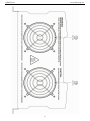
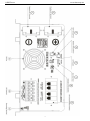
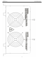
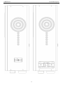
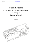
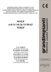
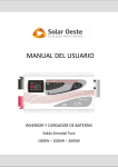
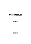
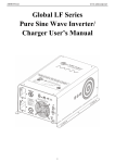
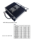
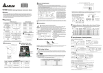
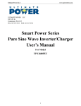
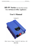
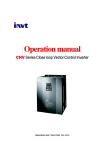
AIMS Power
www.aimscorp.net
Global LF Series
Pure Sine Wave Inverter/
Chargers
5-12KW User’s Manual
Version 4.0
(Code: 614-01208-00 / Updated on NOV 14th 2013)
1
AIMS Power
www.aimscorp.net
Table of Contents
1. Important Safety Information ........................................................................................................................ 3
1-1. General Safety Precautions ......................................................................................................................... 3
1-2. Precautions When Working with Batteries ................................................................................................ 3
2. Introduction .................................................................................................................................................... 4
2-1. General Information ................................................................................................................................... 4
2-2. Application.................................................................................................................................................. 4
2.3 Mechanical Drawing .................................................................................................................................... 5
2-4. Features ..................................................................................................................................................... 10
2.5 Electrical Performance ............................................................................................................................... 10
2.5.1 Invert ................................................................................................................................................ 10
2.5.2 AC Charger ...................................................................................................................................... 10
2.5.3 Transfer ............................................................................................................................................ 13
2.5.4 Manual Frequency Switch ............................................................................................................... 13
2.5.5 Power Saver ..................................................................................................................................... 14
2.5.6 Protections........................................................................................................................................ 15
2.5.7 Remote Control ................................................................................................................................ 15
2.5.8 LED & LCD Indicator ..................................................................................................................... 16
2.5.9 Audible Alarm ................................................................................................................................. 18
2.5.10 FAN Operation............................................................................................................................... 18
2.5.11 DIP Switches .................................................................................................................................. 18
2.5.12 Other Features ................................................................................................................................ 20
3 Installation..................................................................................................................................................... 21
3.1 Location .............................................................................................................................................. 21
3.2 DC Wiring........................................................................................................................................... 21
3.3 AC Wiring........................................................................................................................................... 22
3.4 Grounding ........................................................................................................................................... 24
3.5 Install Flange ....................................................................................................................................... 24
4 Troubleshooting Guide ................................................................................................................................. 26
5 Warranty ....................................................................................................................................................... 28
Appendix 1 ....................................................................................................................................................... 29
2
AIMS Power
www.aimscorp.net
1. Important Safety Information
WARNING! Before using the Inverter, you need to read and save the safety instructions.
1-1. General Safety Precautions
1-1-1.Do not expose the Inverter to rain, snow, spray, bilge or dust. To reduce risk of hazard, do not cover or
obstruct the ventilation openings. Do not install the Inverter in a zero-clearance compartment. Overheating
may result. Allow at least 30CM of clearance around the inverter for air flow. Make sure that the air can
circulate freely around the unit. A minimum air flow of 145CFM is required.
1-1-2. To avoid risk of fire and electronic shock, make sure that existing wiring is in good electrical
condition and that the wire is not undersized. Do not operate the Inverter with damaged or substandard
wiring.
1-1-3. This equipment contains components which may produce arcs and/or sparks. To prevent fire and/or
explosion do not install in compartments containing batteries or flammable materials or in a location which
require ignition protected equipment. This includes any space containing gasoline-powered machinery, fuel
tanks, or joints, fittings, or other connection between components of the fuel system.
See Warranty for instructions on obtaining service.
1-1-4. Do not disassemble the Inverter/Charger. It contains no user-serviceable parts. Attempting to service
the Inverter/Charger yourself may result in electrical shock or fire. Internal capacitors remain charged after
all power is disconnected.
1-1-5. To reduce the risk of electrical shock, disconnect both AC and DC power from the Inverter/Charger
before attempting any maintenance or cleaning. Turning off controls will not reduce this risk
CAUTION: Equipment damage
The output side of the inverter’s AC wiring should at no time be connected to public power or a generator.
This condition is far worse than a short circuit. If the unit survives this condition, it will shut down until
corrections are made.
Installation should ensure that the inverter’s AC output is, at no time, connected to its AC input.
Warning: Limitations On Use
SPECIFICALLY NOTE THAT THE GLOBAL LF INVERTER/CHARGER SHOULD NOT BE USED IN
CONNECTION WITH LIFE SUPPORT SYSTEMS OR OTHER MEDICAL EQUIPMENT OR DEVICES.
1-2. Precautions When Working with Batteries
1-2-1. If battery acid contacts skin or clothing, wash immediately with soap and water. If acid enters eye,
immediately flood eye with running cold water and get medical attention immediately.
1-2-2. Never smoke or allow a spark or flame in the vicinity of a battery or engine.
1-2-3. Do not drop a metal tool on the battery. The resulting spark or short-circuit on the battery may cause
an explosion.
1-2-4. Remove personal metal items such as rings, bracelets, necklaces, and watches when working with a
lead-acid battery. A lead-acid battery produces a short-circuit current high enough to weld a ring or the like
to metal, causing a severe burn.
1-2-5. To reduce the risk of injury, charge only deep-cycle lead acid, lead antimony, lead calcium gel cell,
absorbed mat, or NiCad/NiFe type rechargeable batteries. Other types of batteries may burst, causing
personal injury and damage.
3
AIMS Power
www.aimscorp.net
2. Introduction
2-1. General Information
Global LF Series Pure Sine Wave Inverter is a combination of an inverter, battery charger and AC
auto-transfer switch into one complete system with a peak conversion efficiency of 88%.
It is packed with unique features and it is one of the most advanced inverter/chargers in the market today.
It features power factor corrected, sophisticated multi-stage charging and pure sine wave output with
unprecedentedly high surge capability to meet demanding power needs of inductive loads without
endangering the equipment.
For the regular model, when utility AC power cuts off(or falls out of acceptable range), the transfer relay is
de-energized and the load is automatically transferred to the Inverter output. Once the qualified AC utility is
restored, the relay is energized and the load is automatically reconnected to AC utility.
The Global LF Series Inverter is equipped with a powerful charger.
The overload capacity is 300% of continuous output for up to 20 seconds to reliably support tools and
equipment longer
Another important feature is that the inverter can be easily customized to Battery priority via a DIP switch,
this helps to extract maximum power from the battery in renewable energy systems.
Thus, the Global LF Series Pure Sine Wave Inverter is suitable for Renewable energy systems, Utility, RV,
Marine and Emergency appliances.
To get the most out of the power inverter, it must be installed, used and maintained properly. Please read the
instructions in this manual before installing and operating.
2-2. Application
Power tools–circular saws, drills, grinders, sanders, buffers, weed and hedge trimmers, air compressors.
Office equipment – computers, printers, monitors, facsimile machines, scanners.
Household items – vacuum cleaners, fans, fluorescent and incandescent lights, shavers, sewing machines.
Kitchen appliances – coffee makers, blenders, ice markers, toasters.
Industrial equipment – metal halide lamp, high – pressure sodium lamp.
Home entertainment electronics – television, VCRs, video games, stereos, musical instruments, satellite
equipment.
4
AIMS Power
www.aimscorp.net
2.3 Mechanical Drawing
The PICOGLF 5-12KW inverters may come in two differente enclosures.
5
AIMS Power
www.aimscorp.net
6
AIMS Power
www.aimscorp.net
7
AIMS Power
www.aimscorp.net
8
AIMS Power
www.aimscorp.net
9
AIMS Power
www.aimscorp.net
2-4. Features
High overload ability up to 300% of rated power (20 sec)
Low quiescent current, low power “Power Saving Mode” to conserve energy
Automatic Generator Start
Battery Temperature Sensing for increased charging precision
4-step intelligent battery charger, PFC (Power Factor Correction) for charger
8 pre-set battery type selector switch plus de-sulphation for totally flat batteries
Powerful charge rate of up to 105Amp, selectable from 0%-100%
10 ms typical transfer time between battery and AC, guarantees power continuity
Smart remote control
15s delay before transfer when AC resumes, extra protection for loads when used with generator
Allows start up and through power with depleted batteries
Multiple controlled cooling fans
Extensive protections against various harsh situations
13VDC battery recovery point, dedicated for renewable energy systems
2.5 Electrical Performance
2.5.1 Invert
Topology
The Global LF inverter/charger is built according to the following topology.
Invert: Full Bridge Topology.
Charge: Isolated Boost Topology
Because of high efficiency Mosfets and 16bit, 4.9MHZ microprocessor and heavy transformers, it outputs
PURE SINE WAVE AC with an average THD of 5% (min 3%, max 7% under full linear loads) depending
of load connected and the battery voltage.
The peak efficiency of the Global LF series is 88%.
Overload Capacity
The Global LF series inverters have high overload capacities, making it ideal to handle demanding loads.
1 For 110%<Load<125%(±10%), no audible alarm for 14 minutes, beeps 0.5s every 1s in the 15th minute,
and Fault(Turn off) after the 15th minute.
2 For 125%<Load<150%(±10%), beeps 0.5s every 1s and Fault(Turn off) after 1 minute.
3 For 300%≧Load>150%(±10%), beeps 0.5s every 1s and Fault(Turn off) after 20s.
Caution:
After the inverter is switched on, it takes a finite time for it to self diagnose and get ready to deliver full
power. Hence, always switch on the load(s) after a few seconds of switching on the inverter. Avoid
switching on the inverter with the load already switched on. This may prematurely trigger the overload
protection. When a load is switched on, it may require initial higher power surge to start. Hence, if multiple
loads are being powered, they should be switched on one by one so that the inverter is not overloaded by the
higher starting surge if all the loads are switched on at once.
2.5.2 AC Charger
10
AIMS Power
www.aimscorp.net
Global LF Series is equipped with an active PFC (Power Factor Corrected) multistage battery charger. The
PFC feature is used to control the amount of power used to charge the batteries in order to obtain a power
factor as close as possible to 1.
Unlike other inverters whose max charging current decreases according to the input AC voltage, Global LF
series charger is able to output max current as long as the input AC voltage is in the range of
164-243VAC(95-127VAC for 120V model), and AC freq is in the range of 48-54Hz(58-64Hz for 60Hz
model).
The Global LF series inverter has a very rapid charge current available, and the max charge current can be
adjusted from 0%-100% via a liner switch to the right of the battery type selector. This will be helpful if you
are using our powerful charger on a small capacity battery bank. Fortunately, the liner switch can effectively
reduce the max charging current to 20% of its peak.
Choosing “0” in the battery type selector will disable the charging function.
Caution:
Pls turn the charge current control switch gently to avoid breakage due to over-turning.
There are 3 charging stages:
Bulk Charging: This is the initial stage of charging. While Bulk Charging, the charger supplies the battery
with controlled constant current. The charger will remain in Bulk charge until the Absorption charge voltage
(determined by the Battery Type selection) is achieved.
A software timer will measure the time from A/C start until the battery charger reaches 0.3V below the boost
voltage, then take this time asT0 and T0×10 = T1.
Absorb Charging: This is the second charging stage and begins after the absorb voltage has been reached.
Absorb Charging provides the batteries with a constant voltage and reduces the DC charging current in order
to maintain the absorb voltage setting.
In this period, the inverter will start a T1 timer; the charger will keep the boost voltage in Boost CV mode
until the T1 timer has run out. Then drop the voltage down to the float voltage. The timer has a minimum
time of 1 hour and a maximum time of 12 hours.
Float Charging: The third charging stage occurs at the end of the Absorb Charging time. While Float
charging, the charge voltage is reduced to the float charge voltage (determined by the Battery Type
selection*). In this stage, the batteries are kept fully charged and ready if needed by the inverter.
If the A/C is reconnected or the battery voltage drops below 12Vdc/24Vdc, the charger will restart the above
cycle.
If the charge maintains the float state for 10 days, the charger will deliberately reset the cycle to protect the
battery.
11
AIMS Power
Battery type selector
Switch setting
0
1
2
3
4
5
6
7
8
9
www.aimscorp.net
Description
Charger Off
Gel USA
AGM 1
AGM 2
Sealed lead acid
Gel EURO
Open lead acid
Calcium
De-sulphation
Not used
Boost / Vdc
Float / Vdc
14.0
14.1
14.6
14.4
14.4
14.8
15.1
15.5 (4 Hours then Off)
13.7
13.4
13.7
13.6
13.8
13.3
13.6
12Vdc Mode (*2 for 24Vdc ; *4 for 48Vdc)
De-sulphation
The de-sulphation cycle, switch position 8, is marked in red because this is a very dangerous setting if you
do not know what you are doing. Before attempting to use this cycle you must clearly understand what it
does and when and how you would use it.
What causes sulphation? This can occur with infrequent use of the batteries, or if the batteries have been
discharged so low that they will not accept a charge. This cycle is a very high voltage charge cycle designed
to try to break down the sulphated crust that is preventing the plates from taking a charge and thus allow the
plates to clean up and accept a charge once again.
Charging depleted batteries
The Global LF series inverter allows start up and through power with depleted batteries.
12
AIMS Power
www.aimscorp.net
For 12VDC models: after the battery voltage goes below 10V and the power switch is kept in the "ON"
position and the inverter stays connected to the battery and the battery voltage doesn’t drop below 2V, the
inverter will be able to charge the battery once qualified AC inputs are present.
Before the battery voltage goes below 9VDC, the charging can be activated when the switch is turned to
“Off”, then to “ON”.
When the voltage goes below 9VDC, and you accidently turn the switch to OFF or disconnect the inverter
from the battery, the inverter will not be able to charge the battery once again, because the CPU loses
memory during this process.
Charging current for each model
Model
PICOGLF50W24V230V
PICOGLF50W24V230VS
PICOGLF50W48V230V
PICOGLF50W48V230VS
PICOGLF60W24V230V
PICOGLF60W24V230VS
PICOGLF60W48V230V
PICOGLF60W48V230VS
PICOGLF80W48V230VS
PICOGLF10KW48V230VS
PICOGLF12KW48V230VS
Current
Model
Current
70+/-5A
PICOGLF50W24V120V
55+/-5A
40+/-5A
PICOGLF50W48V120V
30+/-5A
85+/-5A
PICOGLF60W24V120V
75+/-5A
55+/-5A
PICOGLF60W48V120V
45+/-5A
80+/-5A
100+/-5A
120+/-5A
The charging capacity will go to peak charge rate in about 3 seconds. This may cause a generator to drop
frequency, making the inverter transfer to battery mode.
It is suggested to gradually put the charging load on the generator by switching the charging switch from
min to max. Together with the 15s switch delay our inverter gives the generator enough time to spin up.
This will depend on the size of the generator and rate of charge.
2.5.3 Transfer
While in the Standby Mode, the AC input is continually monitored. Whenever AC power falls below the
VAC Trip voltage (154 VAC, default setting for 230VAC,90VAC for 120VAC), the inverter automatically
transfers back to the Invert Mode with minimum interruption to your appliances - as long as the inverter is
turned on. The transfer from Standby mode to Inverter mode occurs in approximately 10 milliseconds. And
it is the same time from Inverter mode to Standby mode.
Though it is not designed as a computer UPS system, this transfer time is usually fast enough to keep your
equipment powered up.
There is a 15-second delay from the time the inverter senses that continuously qualified AC is present at the
input terminals to when the transfer is made. This delay is built in to provide time for a generator to spin-up
to a stable voltage and avoid relay chattering. The inverter will not transfer to generator until it has locked
onto the generator’s output. This delay is also designed to avoid frequent switching when input utility is
unstable.
2.5.4 Manual Frequency Switch
13
AIMS Power
www.aimscorp.net
All our Global LF line of inverters have a 50/60 hz selector switch. When the inverter is turned off and shore
power is not present, the frequency of the inverter may be selected to be 50 or 60 hz.
2.5.5 Power Saver
There are 2 different working statuses for our Global LF inverter: “Power On” and “Power Off”.
When the power switch is in “Unit Off” position, the inverter is powered off.
When the power switch is turned to either of “Power Saver Auto” or “Power Saver Off”, the inverter is
powered on.
Power saver function is designed to conserve battery power when AC power is not or rarely required by the
loads.
In this mode, the inverter pulses the AC output looking for an AC load (i.e., electrical appliance). Whenever
an AC load (greater than 25 watts) is turned on, the inverter recognizes the need for power and automatically
starts inverting and output goes to full voltage. When there is no load (or less than 25 watts) detected, the
inverter automatically goes back into search mode to minimize energy consumption from the battery bank.
In “Power saver on” mode, the inverter will draw power mainly in sensing moments, thus the idle
consumption is significantly reduced.
The inverter is factory defaulted to detect a load for 250ms every 30 seconds. This cycle can be customized
to 3 seconds thru SW3 on the DIP switch.
Power saver on
Power saver off
Power saver on(Load detected)
Note: The minimum power of a load to take inverter out of sleep mode (Power Saver On) is 25 Watts.
The Global LF Series is designed with extraordinarily low idle power consumption which is only a mere
0.8-1.8% of its rated power.
Global LF Series Idle Power Consumption (in Watts)
Model NO
PICOGLF50W24V230V
PICOGLF50W24V230VS
PICOGLF50W24V120V
PICOGLF50W48V230V
PICOGLF50W48V230VS
PICOGLF50W48V120V
PICOGLF60W24V230V
PICOGLF60W24V230VS
Power Saver Off
Power Saver On (3Secs)
62.5
24.2
70
30
68.5
26.2
70
30
76.8
29
14
AIMS Power
www.aimscorp.net
PICOGLF60W24V120V
87
35
80.7
30.3
87
35
100
30
PICOGLF10KW48V230VS
150
35
PICOGLF12KW48V230VS
200
40
PICOGLF60W48V230V
PICOGLF60W48V230VS
PICOGLF60W48V120V
PICOGLF80W48V230VS
When in the search sense mode, the green power LED will blink and the inverter will make a ticking sound.
At full output voltage, the green power LED will light steadily and the inverter will make a steady humming
sound. When the inverter is used as an “uninterruptible” power supply the search sense mode or “Power
Saver On” function should be defeated.
Exceptions
Some devices when scanned by the load sensor cannot be detected. Small fluorescent lights are the most
common example. (Try altering the plug polarity by turning the plug over.) Some computers and
sophisticated electronics have power supplies that do not present a load until line voltage is available. When
this occurs, each unit waits for the other to begin. To drive these loads either a small companion load must
be used to bring the inverter out of its search mode, or the inverter may be programmed to remain at full
output voltage (Power On mode).
2.5.6 Protections
The Global LF series inverter is equipped with extensive protections against various harsh situations/faults.
These protections include:
AC Input over voltage protection/AC Input low voltage protection
Low battery alarm/High battery alarm
Over temperature protection/Over load protection
Short Circuit protection (1s after fault)
Back feeding protection
When Over temperature /Over load occur, after the fault is cleared, the master switch has to be reset to
restart the inverter.
The Low battery voltage trip point can be customized from a defaulted value of 10VDC to 10.5VDC thru
SW1 on the DIP switch.
The inverter will go to Over temp protection when the heat sink temp. ≥105ºC(221℉), and go to Fault
(shutdown Output) after 30 seconds. The switch has to be reset to activate the inverter.
The Global LF series Inverter has back feeding protection which avoids presenting an AC voltage on the AC
input terminal in Invert mode.
After the reason for the fault is cleared, the inverter has to be reset to start working.
2.5.7 Remote Control
15
AIMS Power
www.aimscorp.net
Apart from the switch panel on the front (or top) of the inverter,
an extra switch panel connected to the RJ11 port at the DC side of
the inverter thru a standard telephone cable can also control the
operation of the inverter (sold separately Part #
PICGLFREMOTE).
If an extra switch panel is connected to the inverter via “remote
control port”, together with the panel on the inverter case, the two
panels will be connected and operated in parallel.
Whichever first switches from “Off” to “Power saver off” or
“Power saver on”, it will power the inverter on.
If the commands from the two panels conflict, the inverter will operate according to the following priority:
Power saver on> Power saver off> Power off
Only when both panels are turned to the “Unit Off” position, will the inverter be powered off.
The Max length of the cable is 10 meters.
WARNING
Never cut the telephone cable when the cable is attached to inverter and battery is connected to the inverter.
Even if the inverter is turned off, it will damage the remote PCB inside if the cable is short circuited during
cutting.
2.5.8 LED & LCD Indicator
16
AIMS Power
SHORE POWER ON
INVERTER ON
FAST CHARGE
FLOAT CHARGE
OVER TEMP TRIP
OVER LOAD TRIP
POWER SAVER ON
www.aimscorp.net
GREEN LED lit in AC Mode
GREEN LED lit in Inverter Mode
Yellow LED lit in Fast Charging Mode
GREEN LED lit in Float Charging Mode
RED LED lit in Over Temperature
RED LED lit in Over Load
GREEN LED lit in Power Saver Mode (Power Saver
Load ≦25W)
The LCD will display the following content:
Greeting message of “Welcome to AIMS POWER”
AC Status & Input Voltage
“AC: abnormal” is displayed when AC input is not qualified.
Output Voltage/Frequency and Output Current( in percentage) in Inverter mode
Battery voltage
Note:
When the inverter is in Battery Priority mode, finishes a complete charging cycle and switches to inverter
mode “AC:abnormal” will be displayed.
In AC mode, the LCD will not display the status of the AC load.
17
AIMS Power
www.aimscorp.net
2.5.9 Audible Alarm
Inverter green LED lit, and the buzzer beeps 0.5s every 5s.
Inverter green LED lit, and the buzzer beeps 0.5s every 1s and Fault after
60s.
(1)110%<load<125%(±10%), No audible alarm in 14 minutes,
Beeps 0.5s every 1s in 15th minute and Fault after 15 minutes;
(2)125% <load<150%(±10%), Beeps 0.5s every 1s and Fault after 60s;
(3)Load>150%(±10%), Beeps 0.5s every 1s and Fault after 20s;
Heat sink temp. ≥105ºC(221℉), Over temp red LED Lighting, beeps 0.5s
every 1s;
Battery Voltage Low
Battery Voltage High
Invert Mode Over-Load
Over Temperature
2.5.10 FAN Operation
All models (6kW and up) have 2 dc fans
12kW also has 1 ac fan that will turn on when there is ac output
So when the inverter is in power saver mode, the AC fan will work from time to time in response to the
pulse sent by the inverter in power saver mode.
The dc fans are variable speed and work as follows:
Condition
HEAT SINK
TEMPERATURE
CHARGER
CURRENT
LOAD Percentage
(INV MODE)
Enter Condition
T ≤ 60℃(140℉)
65℃(149℉)≤ T < 85 ℃(185℉)
T > 85℃(185℉)
I ≤ 15%
20%< I ≤ 50%Max
I > 50%Max
Load < 30%
30% ≤ Load < 50%
Load ≥ 50%
Leave condition
T > 65℃(149℉)
T ≤ 60℃(140℉) or T ≥ 85℃(185℉)
T ≤ 80℃(176℉)
I ≥ 20%
I≤ 15% or I > 50%Max
I ≤ 40%Max
Load ≥ 30%
Load ≤ 20% or Load ≥ 50%
Load ≤ 40%
Speed
OFF
50%
100%
OFF
50%
100%
OFF
50%
100%
Allow at least 30CM of clearance around the inverter for air flow. Make sure that the air can circulate freely
around the unit.
Fan noise level <60db at a distance of 1m
2.5.11 DIP Switches
On the DC end of inverter, there are 5 DIP switches which enable users to customize the performance of the
device.
Switch NO
SW1(Utility Priority)
SW1(Battery Priority)
SW2(230V)
SW2(120V)
SW3
Switch Function
Position: 0
10.0VDC
10.5VDC
184-253VAC
100-135VAC
Inverter Off
Low Battery Trip Point
AC Input Range
AC Input Range
Power Save Override
18
Position: 1
10.5VDC
11.5VDC
154-264VAC(40Hz+)
90-135VAC(40Hz+)
Saver On 3 sec
AIMS Power
SW4
SW5
www.aimscorp.net
ON/OFF
Frequency Switch
Battery/AC Priority
50Hz
AC Priority
60Hz
Battery Priority
Low Battery Trip Point(SW1):
Deep discharge of the lead acid battery leads to high losses in capacity and early aging. In different
applications a different low voltage disconnection level is preferred. For example, for solar applications,
user may intend to have less DOD to prolong the battery life cycle. While for mobile applications users may
intend to have more DOD to reduce battery capacity and on board weight.
For 12VDC models, when the inverter is in utility priority mode(SW5 at “0”),Low Battery Trip Point is
selectable at 10.0/10.5VDC. It can be customized to 10.5/11.5VDC via SW5. This is to prevent batteries
from over-discharging while there is only a small load applied on the inverter.
*2 for 24VDC, *4 for 48VDC
AC Input Range(SW2):
There are different acceptable AC input ranges for different kinds of loads.
For some relatively sensitive electronic devices, a narrow input range of 184-253VAC (100-135V for
120VAC model) is required to protect them.
While for some resistive loads which work in a wide voltage range, the input AC range can be customized to
154-264VAC (90-135V for 120VAC model), this helps to power loads with the most AC input power
without frequent switches to the battery bank.
In order to make the inverter accept dirty power from a generator, when the SW2 is switched to position “1”,
the inverter will bypass an AC input with a wider voltage and frequency (40Hz plus for 50Hz/60Hz).
Accordingly, the AC charger will also work in a wider voltage and freq range (43Hz plus for 50Hz/60Hz).
This will avoid frequent switches between battery and generator. But some sensitive loads will suffer from
the low quality power.
The pros and cons should be clearly realized.
Power Save Override ON/OFF (SW3):
Under the Battery Priority Mode (SW5 in position “1”), the inverter can be switched between two modes:
Power Saver Mode (SW3 in position “1”) and Unit Off Charging Mode (SW3 in position “0”). The power
Switch should be in “Power saver on” position all the time for using these functions.
In Power Saver Mode, the inverter is initially in standby mode and sends a pulse to detect the presence of a
load every 3 seconds. Each pulse lasts for 250ms. The inverter will remain in standby mode until a load has
been detected. Then it will wake up from standby mode and start to invert electricity from the battery bank
to supply the load. As this function is under Battery Priority, the inverter will always prefer to invert
electricity from battery first even there is a qualified AC input present.Only when the battery voltage is
lower than the low voltage alarm point, will the inverter switch to AC input power to charge the battery and
supply the load at the same time.
This Power Saver Mode can be changed to Unit Off Charging mode via SW3 by switching it to “0” position.
(SW5 still in “1”)
In Unit Off Charging mode, the inverter will stay in standby mode without sensing loads. It won’t output
any power even if a load is turned on or a qualified AC input is present. The inverter will not perform any
function and only stay idle in this mode, unless the battery voltage is low. Then it will start charging the
battery. This feature is ideally suitable for applications where energy conservation is required. Charging will
only be activated when required.
Frequency Switch(SW4):
19
AIMS Power
www.aimscorp.net
The output frequency of the inverter can be set at either 50Hz or 60Hz by SW4.
AC/Battery Priority(SW5):
Our inverter is designed with AC priority by default. This means, when AC input is present, the battery will
be charged first, and the inverter will transfer the input AC to power the load. Only when the AC input is
stable for a continuous period of 15 days will the inverter start a battery inverting cycle to protect the
battery. After 1 normal charging cycle ac through put will be restored.
The AC Priority and Battery Priority switch is SW5. When you choose battery priority, the inverter will
invert from battery despite the AC input. Only when the battery voltage reaches the low voltage alarm
point(10.5Vdc for 12Vdc, 21Vdc for 24Vdc, 42Vdc for 48Vdc) will the inverter transfer to AC Input, charge
battery, and switch back to battery when the battery is fully charged. This function is mainly for wind/solar
systems using utility power as back up.
Note: In battery priority mode, when qualified AC inputs for the first time and the battery voltage is
below 12.5Vdc(12.5Vdc for 12Vdc, 25Vdc for 24Vdc, 51Vdc for 48Vdc), the inverter will go into
battery priority mode only after a cycle of bulk charging and absorb charging is finished. The inverter
will not go into float charging mode.
2.5.12 Other Features
Battery Temperature Sensing
Applying the proper charge voltage is critical for achieving optimum battery performance and longevity. The
ideal charge voltage required by batteries changes with battery temperature.
The battery temperature sensor allows the charge controller to continuously adjust charge voltage based on
actual battery temperature.
Temperature compensation of charge voltage assures that the battery receives the proper charge voltage as
battery temperature varies.
The entire line of Global LF are equipped with Battery Temperature Sensing for increased charging
precision.
It sends precise information to the charger, which automatically adjusts voltage to help ensure full battery
charge depending on the ambient temperature of your battery installation.
When the battery voltage is over 40℃(104℉), it will reduce the charging voltage by 0.1Vdc with every
degree of temperature rise.
Aims recommends that you install Battery Temperature Sensors on all banks to protect your batteries and to
provide optimal charging of each bank.
The battery temperature sensor mounts on the side of a battery.
The spec is listed below
Inverter Condition
Charger Mode
Inverter Mode
Temp on BST
BTS ≥ 50℃(122℉)
BTS ≤ 40℃(104℉)
Operation
Automatically turns off charger
Automatically turns on charger
Increases the low voltage shut down
40℃(104℉) ≤ BTS ≤ 50℃(122℉)
point by 0.5Vdc
BTS ≥ 50℃(122℉)
Over Temp Fault
20
AIMS Power
www.aimscorp.net
Battery voltage recovery start
After low battery voltage shut off (10V for 12V model or 20V for 24V model or 40V for 48V model), the
inverter is able to restore operation after the battery voltage recovers to 13V/26V/52V (with power switch
still in the “On” position). This function helps to save the users extra labor to reactivate the inverter when
the low battery voltage returns to an acceptable range in renewable energy systems. The built in battery
charger will automatically reactivate as soon as city/generator ac has been stable for 15 seconds.
WARNING
Never leave the loads unattended, some loads (like a Heater) may cause accidents in such cases.
It is better to shut everything off after low voltage trip than to leave your load on, due to the risk of fire.
Auto Gen Start
The inverter can be customized to start up a generator when the battery voltage goes low.
When the inverter goes to low battery alarm, it can send a signal to start a generator, and turn the generator
off after battery charging is finished.
The auto gen start feature will only work with generators designed to work with this feature. There is an
open/close relay that will short circuit the positive and negative cable from a generator. The input DC
voltage can vary, but the Max current the relay can carry is 16Amp.
Conformal Coating
AIMS Power entire line of Global LF inverters have been processed with a conformal coating on the PCB,
making it water, rust, and dust resistant as well as corrosion resistant.
While these units are designed to withstand corrosion from the salty air, they are not splash proof.
3 Installation
3.1 Location
Follow all the local regulations to install the inverter.
Please install the equipment in a location of Dry, Clean, Cool with good ventilation.
Working temperature: ‐10℃‐40℃(-14℉to 104℉)
Storage temperature: ‐40‐70℃(-40℉to 158℉)
Relative Humidity: 0% to 95%,non-condensing
Cooling: Forced air
3.2 DC Wiring
It is suggested the battery bank be kept as close as possible to the inverter. The following is a suggested
wiring option for 3 meter DC cable.
Please find the following minimum wire size. In case of DC cable longer than 3m, please increase the cross section of
cable to reduce the loss.
Inverter Power
DC Input voltage
21
Wire Gage
AIMS Power
www.aimscorp.net
5KW
5KW
6KW
6KW
8KW
10KW
12KW
24Vdc
48Vdc
24Vdc
48Vdc
48Vdc
48Vdc
48Vdc
AWG 4/0
AWG 1/0
AWG 4/0
AWG 1/0
AWG 3/0
AWG 3/0
AWG 3/0
Performance of any product can be improved by thicker cable
and shorter runs, so if in doubt, round up and keep the length as short as possible.
For more wiring configurations for your specific system, please contact AIMS Power for more information.
CAUTION
The torque rating range for DC terminal is 12.5NM-20.5NM, and the suggested torque rating is 17NM.
Over torqueing may cause the bolt to break.
WARNING
In the event of reverse polarity the unit could be totally destroyed and warranty voided!
3.3 AC Wiring
We recommend using 10 to 5Awg wire to connect to the ac terminal block.
When in AC mode the AC input power will supply both the loads and AC charger, a thicker wire gauge for
AC Input is required. Pls consult a qualified electrician about the specific wire gauge required in terms of
wire material and inverter power.
There are 3 different ways of connecting to the terminal block depending on the model. All the wirings are
CE compliant, call our tech support if you are not sure about how to wire any part of your inverter.
Wiring Option 1
230V single phase/120V single
phase
Input: Hot line+Neutral+Ground
Output: Hot line+Neutral+Ground
22
AIMS Power
www.aimscorp.net
Wiring Option 2
230V split phase
Input: Hot line+ Hot line +Ground
Output: Hot line+ Hot line
+Neutral
Wiring Option 3
230V split phase
Input: Hot line+ Hot line +Ground
Output: Hot line +Neutral
Remark: In such case, each output
hotline can only carry a max of
half the rated capacity.
Caution:
Wiring Option 2 and 3 are only allowed for split phase models (last letter of part # “S”).
Pls wire all the other models according to Wiring Option 1.
WARNING
For split phase models, AC input neutral is not required in wiring. Never Connect Input Neutral to
Output Neutral. Damage will result which is not covered under warranty.
Always switch on the inverter before plugging in any appliance.
WARNING
The output voltage of this unit must never be connected in its input AC terminal, overload or damage
may result.
Always switch on the inverter before plugging in any appliance.
23
AIMS Power
www.aimscorp.net
3.4 Grounding
Connect an AWG 8 gauge or greater copper wire between the grounding terminal on the inverter and the
earth grounding system or the vehicle chassis.
3.5 Install Flange
6KW Model
24
AIMS Power
www.aimscorp.net
8KW to 12KW Models
Side View
25
AIMS Power
www.aimscorp.net
4 Troubleshooting Guide
Troubleshooting contains information about how to troubleshoot possible error conditions while using the
Global LF Inverter & Charger.
The following chart is designed to help you quickly pinpoint the most common inverter failures.
Indicator and Buzzer
Indicator on top cover
SHORE
Status
Item
POWER
ON
INVERT
FAST
FLOAT
ER ON
CHG
CHG
LED on Remote Switch
OVER
OVER
POWER
TEMP
LOAD
SAVER
TRIP
TRIP
ON
BATT
INVERTE
CHG
R
Alarm
Buzzer
CC
√
×
√
×
×
×
×
√
×
×
×
Line
CV
√
×
√, blink
×
×
×
×
√
×
×
×
Mode
Float
√
×
×
√
×
×
×
√
×
×
×
Standby
√
×
×
×
×
×
×
×
×
×
×
Inverter On
×
√
×
×
×
×
×
×
√
×
×
×
×
×
×
×
×
√
×
×
×
×
×
√
×
×
×
×
×
×
√
√
×
√
×
×
×
×
×
×
√
√
Inverter
Mode
Power
Saver
Battery
Low
Battery
High
Overload
On Invert
Mode
×
√
×
×
×
√
×
×
√
√
×
√
×
×
√
×
×
×
√
√
√
×
√
×
√
×
×
√
×
√
√
×
√
×
×
×
×
√
×
√
×
×
×
×
×
×
×
×
×
×
×
√
×
×
×
×
×
×
√
×
×
×
×
×
×
√
×
×
×
×
×
×
×
×
×
√
×
×
×
√
×
×
×
×
√
×
×
×
×
×
×
×
√
×
×
×
×
√
×
×
Mode
Over-Temp
On Line
Mode
Over
Charge
Fan Lock
Battery
High
Inverter
Mode
Fault
Mode
Overload
Output
Short
Over-Temp
Over
Charge
Beep 0.5s
every 1s
“Audible
alarm”
Over-Temp
On Invert
every 5s
Refer to
Mode
Inverter
Beep 0.5s
26
Beep 0.5s
every 1s
Beep 0.5s
every 1s
Beep 0.5s
every 1s
Beep
continuous
Beep
continuous
Beep
continuous
Beep
continuous
Beep
continuous
Beep
continuous
AIMS Power
Back Feed
Short
www.aimscorp.net
×
×
Symptom
Inverter will not turn on during
initial power up.
×
×
×
×
Possible Cause
Batteries are not connected, loose
battery-side connections.
×
×
×
×
Beep
continuous
Recommended Solution
Check the batteries and cable
connections. Check DC fuse and
breaker.
Low battery voltage.
No AC output voltage and no
indicator lights ON.
AC output voltage is low and the
inverter turns loads OFF in a short
time.
Charger is inoperative and unit
will not accept AC.
Charger is supplying a lower
charge rate.
Charger turns OFF while charging
from a generator.
Sensitive loads turn off
temporarily when transferring
between grid and inverting.
Noise from Transformer/case*
Inverter has been manually
transitioned to OFF mode.
Low battery.
Charge the battery.
Press the switch to Power saver on
or Power saver off position.
Check the condition of the
batteries and recharge if possible.
AC voltage has dropped
out-of-tolerance
Charger controls are improperly
set.
Check the AC voltage for proper
voltage and frequency.
Refer to the section on adjusting
the “Charger Rate”.
Low AC input voltage.
Source qualified AC power..
Loose battery or AC input
connections.
High AC input voltages from the
generator.
Check all DC /AC connections.
Inverter's Low voltage trip voltage
may be too low to sustain
certain loads.
Applying specific loads such as
hair drier
Load the generator down with a
heavy load.
Turn the generator output voltage
down.
Choose narrow AC voltage in the
DIP switch, or Install a UPS if
possible.
Remove the loads
*The reason for the noise from transformer and/or case
When in inverter mode sometimes the transformer and/or case of the inverter may vibrate and make noise.
If the noise comes from transformer:
According to the characteristics of our inverter, there is one type of load which most likely may cause rattles
of transformer.
That is a half wave load: A load that uses only half a cycle of the power. This tends to cause an imbalance of
the magnetic field of the transformer, reducing its rated working freq from 20KHz to, say, maybe 15KHz (it
varies according to different loads). In such a case the frequency of noise falls exactly into the range
(200Hz-20KHz) that human ears can hear.
The most common load of such kind is a hair drier.
If the noise comes from the case:
Normally when loaded with inductive loads, the magnetic field generated by the transformer keeps attracting
or releasing the steel case at a specific freq, this may also cause noise.
Reducing the load power or using an inverter with bigger capacity will normally solve this problem.
The noise will not do any harm to the inverter or the loads.
27
AIMS Power
www.aimscorp.net
5 Warranty
We offer a 1 year limited warranty.
The following cases are not covered under warranty.
1 DC polarity reverse.
The inverter is designed without DC polarity reverse protection. A polarity reverse may severely damage the
inverter.
2 Wrong AC wiring
3 Operation in a moist environment.
4 Operation with an undersized generator or generator with unqualified wave form. To guarantee the
best performance of inverter, the standby generator should be at least 150% of higher capacity than
the inverter.
AIMS Operating Corp., Inc. dba AIMS Power Warranty Instructions:
This product is designed using the most modern digital technology and under very strict quality control and
testing guide lines. If however you feel this product is not performing as it should, please contact us:
[email protected] or (775)359-6703.
We will do our best to resolve your concerns. If the product needs repair or replacement, make sure to
keep your receipt/invoice, as that will need to be sent back along with the package and RA# prepaid to
AIMS. You have a full 1 year from date of purchase warranty.
This warranty is valid world wide with the exception that freight and duty charges incurred outside the
contiguous 48 United States will be prepaid by customer.
Except as provided above, AIMS makes no warranty of any kind, express or implied, including without
limitation the implied warranties of merchantability and fitness for a particular purpose. In no event shall
AIMS be liable for indirect, special or consequential damages. This warranty only applies to AIMS Power
branded products. All other name brand products are warranted by and according to their respective
manufacturer. Please do not attempt to return non-AIMS Power branded products to AIMS Power.
For additional products such as:
- Modified sine wave inverters
- Pure sine wave inverters
- Solar Charge Controllers
- On Grid Inverters
- Inverter Chargers and Automatic transfer switches
- Custom cut cables
- Batteries
- Solar Panels
Please visit our web site: www.aimscorp.net. To find out where to buy any of our products, you may also
e-mail:[email protected] or call (775)359-6703.
28
AIMS Power
www.aimscorp.net
Appendix 1
Global LF Series Inverter & Charger Spec Sheet
Electrical Specifications
Model
GLFOPIC5KW GLFOPIC6KW GLFOPIC8KW GLFOPIC10KW GLFOPIC12KW
Continuous Output Power
5000W
6000W
8000W
10000W
12000W
Surge Rating(20s)
15000W
18000W
24000W
30000W
36000W
5HP
6HP
8HP
10HP
12HP
Capable of Starting Electric Motor
Inverter Output
Output Waveform
Pure Sine wave/Same as input(Bypass mode)
Nominal Efficiency
>88%(Peak)
Line Mode Efficiency
>95%
Power Factor
0.9-1.0
Nominal Output Voltage RMS
100-110-120Vac / 220-230-240Vac
Output Voltage Regulation
±10% RMS
Output Frequency
50/60Hz ±0.3Hz
Short Circuit Protection
Yes, Current Limit Function (Fault after 1sec)
Typical transfer Time
10ms(Max)
DC Input
THD
Max 7% under full linear load
Nominal Input Voltage
12.0Vdc( *2 for 24Vdc, *4 for 48Vdc)
Minimum Start Voltage
10.0Vdc
Low Battery Alarm
10.5Vdc / 11.0Vdc
Low Battery Trip
10.0Vdc / 10.5Vdc
High Voltage Alarm & Fault
16.0Vdc
High DC Input Recovery
15.5Vdc
Low Battery Voltage Recover
13.0Vdc
Idle Consumption-Search Mode
< 25 W when Power Saver On
Narrow: 100~135VAC / 194~243VAC;
Input Voltage Range
Wide: 90~135VAC / 164~243VAC;
Narrow: 47-55±0.3Hz for 50Hz, 57-65±0.3Hz for 60Hz
Input Frequency Range
Wide:43±0.3Hz plus for 50Hz/60Hz
Output Voltage
Charger Breaker Rating(230Vac)
30A
30A
40A
40A
40A
Charger Breaker Rating(120Vac)
63A
63A
not available
not available
not available
Max Charge Rate
Charge
Depends on battery type
Over Charge Protection Shutdown
Battery type
15A to 120A +/-5A , depending on models, refer to 2.5.2 AC Charger
15.7V for 12Vdc ( *2 for 24Vdc, *4 for 48Vdc)
Fast Vdc
Float Vdc
Gel U.S.A
14.0
13.7
A.G.M 1
14.1
13.4
A.G.M 2
14.6
13.7
Sealed Lead Acid
14.4
13.6
Gel Euro
14.4
13.8
Open Lead Acid
14.8
13.3
Calcium
15.1
13.6
De-sulphation
15.5 for 4hrs
29
AIMS Power
www.aimscorp.net
Remote Control
Yes. Optional
Input Voltage Waveform
Sine wave (Grid or Generator)
Nominal Voltage
120Vac
230Vac
Low Voltage Trip
80V/90V±4%
184V/154V±4%
90V/100V±4%
194V/164V±4%
High Voltage Trip
140V±4%
253V±4%
High Voltage re engage
135V±4%
243V±4%
Max Input AC Voltage
150VAC
270VAC
Bypass & Protection
Low Voltage re engage
Nominal Input Frequency
50Hz or 60Hz (Auto detect)
Narrow: 47±0.3Hz for 50Hz, 57±0.3Hz for 60Hz
Low Freq Trip
Wide:40±0.3Hz for 50Hz/60Hz
Narrow: 48±0.3Hz for 50Hz, 58±0.3Hz for 60Hz
Low Freq re engage
Wide:45±0.3Hz for 50Hz/60Hz
Narrow: 55±0.3Hz for 50Hz, 65±0.3Hz for 60Hz
High Freq Trip
Wide: No up limit for 50Hz/60Hz
Narrow: 54±0.3Hz for 50Hz, 64±0.3Hz for 60Hz
High Freq re engage
Wide: No up limit for 50Hz/60Hz
Output Short circuit protection
Circuit breaker
Bypass breaker rating(230Vac)
40A
40A
50A
63A
63A
Bypass breaker rating(120Vac)
80A
80A
not available
not available
not available
Mechanical Specification
Mounting
Inverter Dimensions(L*W*H)
Inverter Weight
Shipping Dimensions(L*W*H)
Shipping Weight
Wall mount
488*415*200mm/
588*415*200mm /
19.3*16.3*7.9”
23.3*16.3*7.9”
45KG/99lbs
46KG/101lbs
55KG/132
lbs
66KG/145.5 lbs
660*540*410mm/
760*540*410mm/
26*21.3*16.1”
30*21.3*16.1”
57KG/126lbs
58KG/128lbs
Display
68KG/150
lbs
79KG/174 lbs
Status LEDs+LCD
Standard Warranty
1 Year
※Specifications in this manual are subject to change without prior notice.
30
70KG/154 lbs
82KG/181 lbs