1
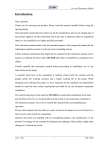
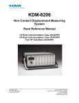
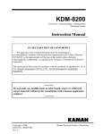
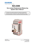
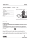
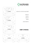
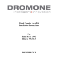
ThreadChecker
Universal
TM
Noncontact Thread Detection
System User’s Manual
Copyright © 2008
PART NO: 860510-001A
Last Revised: 6/8/11
Kaman Aerospace Corporation
Kaman Precision Products
Measuring & Memory Systems
217 Smith Street
Middletown, CT 06457
www.kamansensors.com or 860-632-4442
Page 1 of 13
This apparatus, when installed and operated per the manufacturer’s recommendations,
conforms with the protection requirements of EC Council Directive 89/336/EEC on the
approximation of the laws of the member states relating to Electromagnetic Compatibility.
Please refer to the Declaration of Conformity or contact Kaman Precision Products for
details.
Copyright © 2008
PART NO: 860510-001A
Last Revised: 6/8/11
Kaman Aerospace Corporation
Kaman Precision Products
Measuring & Memory Systems
217 Smith Street
Middletown, CT 06457
www.kamansensors.com or 860-632-4442
Page 2 of 13
ThreadChecker Universal
Kaman’s ThreadChecker Measuring System is a noncontact linear proximity measuring
system. This low-cost, easy-to-use system makes precision static and dynamic
measurements of the presence or absence of a thread.
Features Summary / Advantages
•
•
•
•
•
•
•
•
Easy to Use
Universal Electronics for All Sensor Types and Target Types
Built in Self Test
Small size for efficient system integration: less than 4 cubic inches (80cc)
Flexible packaging and performance.
Several sensor options.
Flexible Switched Output Options (window or level comparator / inversion of limit)
available to user
Low power consumption
ThreadChecker Unit
The ThreadChecker system consists of two subassemblies: the sensor with integrated
cable, and the signal conditioning electronics module with power and output cable. The
ThreadChecker electronics uses a standard 24AWG cable to bring +15 Vdc to +30 Vdc
into the electronics and provide outputs for the analog voltage and switch functions.
Theory of Operation
The ThreadChecker system is an eddy current system. The sensor coil is resonated
and the amount of impedance change in the output is measured by the electronics. The
proximity of the target to the sensor coil will cause the sensor coil to change impedance.
The signal is then processed and filtered to obtain an analog voltage proportional to
the target position or displacement.
Cable Connections and Power I/O Cable Color Chart:
Wire Color
BROWN
BLUE
WHITE
BLACK
Signal
Vin 15-30vdc
GND
SWITCHED OUTPUT
Vout 0-10v
Copyright © 2008
PART NO: 860510-001A
Last Revised: 6/8/11
Kaman Aerospace Corporation
Kaman Precision Products
Measuring & Memory Systems
217 Smith Street
Middletown, CT 06457
www.kamansensors.com or 860-632-4442
Page 3 of 13
Electronics
The ThreadChecker electronics has one switch and two LEDs visible in the enclosure to
provide various setup and status functions. The power led indicates that power is
applied and everything is functional if it is green. Red or flashing red on the power LED
indicates a problem. The thread or status LED indicates the presence or absence of a
thread or teach status (see application information).
The ThreadChecker electronics and sensors utilize SMA type coaxial connectors: female
on the electronics, and male on the sensor cable. Four probe configurations for
detecting internal threads are currently available from 2mm to 10mm, and two probe
configurations for detecting external threads are available, more configurations are
created regularly (check with Kaman sales for current configurations). The sensor must
be attached snugly (finger tight) to the electronics assembly for the unit to function
properly.
Adjustment and Calibration
The ThreadChecker requires calibration to the users configuration before use.
NOTE: solid red on the power LED means that it does not recognize the sensor or
the sensor is disconnected. If the sensor is connected and this condition persists
after a teach then the electronics does not recognize the sensor and it may be faulty.
The switched output can be adjusted using the teach modes. See application
information for more details.
Switched Output Operation
The ThreadChecker’s switched output is a simple on / off switch. The switch can be
adjusted to trip anywhere along the sensor range using application teach modes.
Cleaning
The ThreadChecker is designed to have limited operation while immersed in liquids.
Some solvents may damage electronics module, sensor, or power I/O cable. Clean the
unit with a damp cloth.
EMI Performance
The ThreadChecker conforms with the applicable standards of Council Directive for
Generic for Light Industrial and Commercial Use. Under some EMI environments, at
specific frequencies, the ThreadChecker unit may experience a change in output
voltage. In general, when exposed to those environments covered by the EMC directive,
the user can expect less than 5% deviation of output. Contact Kaman for specific data
or for recommended solutions if you experience problems with the ThreadChecker.
Copyright © 2008
PART NO: 860510-001A
Last Revised: 6/8/11
Kaman Aerospace Corporation
Kaman Precision Products
Measuring & Memory Systems
217 Smith Street
Middletown, CT 06457
www.kamansensors.com or 860-632-4442
Page 4 of 13
Operation of the ThreadChecker
Wire colors & pin-out.
The wire colors and typical connection diagram are as follows.
Teach sequence
Before the system is first used it must have the ‘teach’ sequence run. In order to do
this you must have a representative threaded and non-threaded hole. The system can
be easily calibrated to any new sensor designed for the ThreadChecker as well as for
most hole/thread configurations with a simple calibration sequence.
1. Connect the sensor and power source to the electronics. Allow the system to
warm up for a minimum of 5 minutes.
2. With the sensor in ‘air’ (i.e. not in a hole or near any conductive material), press
and hold the ‘Teach’ button until the Thread LED blinks fast then release (more
than 1 second but less than 10 seconds), the Thread LED should blink slowly.
3. Position the sensor tip in the threaded hole and momentarily press the ‘Teach’
button. The Status LED will blink fast.
4. Position the sensor in an unthreaded or bad hole and momentarily press the
‘Teach’ button. The LED should be solid red indicating no threads present. The
system is now calibrated and ready for use.
Since the switch point is half way between these 2 points you can teach these in
reverse order (bad then good) if desired.
Copyright © 2008
PART NO: 860510-001A
Last Revised: 6/8/11
Kaman Aerospace Corporation
Kaman Precision Products
Measuring & Memory Systems
217 Smith Street
Middletown, CT 06457
www.kamansensors.com or 860-632-4442
Page 5 of 13
The Switched output
This is an opto-coupled solid-state relay. While the switched output can handle a
substantial amount of voltage & current (see specifications) it is not infinite. Connect
external devices accordingly. There are two modes of operation for the switched
output: Window comparator and compatibility/level comparator mode. You can easily
switch between the two modes by holding down the button on power up. It will
remember the last mode it was set up for the next time you power on. The ‘ON’ polarity
of the switch can also be inverted. Operation is as follows:
Standard Window Comparator Mode
In standard mode it is a ‘window’ comparator. The switch will be closed (to ground)
when it detects a threaded (or “good”) hole. Otherwise the switch will be open.
Compatibility (Level comparator) Mode
In ‘compatibility’ mode the switch is open when detecting no thread, and closed (to
ground) when it detects a thread or open air.
Inverting the Switch Polarity
The polarity of this output can be inverted (in either mode) so that the open and closed
stated are reversed. To do this; after the unit is powered on, press and hold the teach
button on the unit for more than 10 seconds. To re-invert the output press and hold the
teach button for more than 10 seconds after the unit has been powered on. Note that
in compatibility mode the status led mirrors the opto-isolated switch state.
The Analog Output
The analog output will read a 5V difference between the threaded and unthreaded
holes after calibration. The ‘air’ (i.e. no target) value will always be the highest voltage
and will be at or near saturation (10V). The direction of the output depends on the
sensor and target type but typically for aluminum targets the system will read 7.5V on
the threaded hole and 2.5V on the unthreaded hole while for magnetic (or ferrous)
target it will read 7.5V on the unthreaded hole and 2.5V on the threaded hole. For
small diameter sensors in large diameter holes there ends up being a substantial
amount of gain on the analog output and so it may appear to be noisy.
Copyright © 2008
PART NO: 860510-001A
Last Revised: 6/8/11
Kaman Aerospace Corporation
Kaman Precision Products
Measuring & Memory Systems
217 Smith Street
Middletown, CT 06457
www.kamansensors.com or 860-632-4442
Page 6 of 13
The LED’s
There are two bi-color LED’s on the system. The power LED (labeled PWR) displays
whether the system is running or has a fault. The status LED (labeled THREAD)
displays the limit output and can flash at different calibration points.
The function of the status LED in the Thread Checker is to indicate the state of the
switched output. In ‘compatibility’ mode the status LED output mirrors the switch state.
When the LED is “off” the switch output is pulled to ground. When the LED is “on” the
output is open.
In standard ‘Window’ comparator mode, the status LED functionality is NOT affected by
the limit inversion and will continue to operate with green indicating a ‘good’ or
threaded hole, red indicating a ‘bad’ or non-threaded hole, and off as no target.
POWER LED
Green
Red
Red Flashing Fast
Yellow
Off
System is running with no faults
Solid red on the power LED means that it does
not recognize the sensor or it is disconnected.
If the sensor is connected and this condition
persists after a “teach” then the electronics
does not recognize the sensor and it may be
faulty.
The system has a fault (calibration error, power
input too low, etc.) – Most likely calibration error
with points too close together
The system is being calibrated or the button is
pushed
System has no power or is otherwise faulty
Copyright © 2008
PART NO: 860510-001A
Last Revised: 6/8/11
Kaman Aerospace Corporation
Kaman Precision Products
Measuring & Memory Systems
217 Smith Street
Middletown, CT 06457
www.kamansensors.com or 860-632-4442
Page 7 of 13
Dwell time and Frequency
When the sensor is being inserted into a hole there is a certain period of ambiguity at
partial insertion. To avoid switching on this ambiguity a form of derivative is used to
determine whether the sensor is in motion or is at the measurement point. The system
will effectively delay of approximately 10-20 milliseconds after it stops moving before it
recognizes the values for the limits (the analog output does not do this and is
continuous). If this delay is too short for the application it can be adjusted at the
factory. If the delay is a problem for the application and there is another method of
determining when a reading is valid then the delay can be turned off by holding down
the button for more than 10 seconds during power up (until the led turns on). It can be
toggled back on by the same method.
Positioning/Mounting the sensor
Ideally the sensor should be just slightly smaller than (and centered in) the untapped
hole. The surface of the sensor tip should be at mid depth.
Larger – For holes that are much larger than the sensor, the mounting can be offset so
that the sensor is near the threaded edge. While this will be able to detect the presence
or absence of a thread there are a couple of limitations. First, only a small section of
the tapped hole is being tested. Second, generally the signal strength is lower. This
results in lower resolution.
Smaller – For holes that are smaller than the sensor, the sensor can be mounted near
the surface of the material and measure down into the hole. The main limitation here is
that there is a limited depth that the sensor can detect threads (near the max range of
the sensor). There is also a limitation on very small holes (where the diameter of the
hole is less than half the diameter of the sensor).
Copyright © 2008
PART NO: 860510-001A
Last Revised: 6/8/11
Kaman Aerospace Corporation
Kaman Precision Products
Measuring & Memory Systems
217 Smith Street
Middletown, CT 06457
www.kamansensors.com or 860-632-4442
Page 8 of 13
Push Button Switch Operation and User Configuration
Switch Operation
Holding the button down for longer than
one second
Holding switch down during power up for
less than 10 seconds
Holding switch down during power up for
more than 10 seconds
Holding switch down for longer than 10
seconds (until the status light stops
blinking)
Result
The status light starts blinking. On release it
acquires the air readings for all frequencies.
The next step is to put the sensor in a threaded
hole and press the button again. On release
the system will acquire a set of calibration data
for all frequencies for the threaded hole. The
last step is to put the sensor in a non-threaded
hole and press the button again. On release
the system will acquire data for all frequencies
for the non-threaded hole, optimize the sensor
frequency and modality, and set the limits.
Toggles between window comparator and level
comparator
Status LED will turn yellow and when the
switch is released it will toggle the Dwell
Enable (i.e. whether or not you are using the
derivative to check the limits)
Limits are inverted
Copyright © 2008
PART NO: 860510-001A
Last Revised: 6/8/11
Kaman Aerospace Corporation
Kaman Precision Products
Measuring & Memory Systems
217 Smith Street
Middletown, CT 06457
www.kamansensors.com or 860-632-4442
Page 9 of 13
Troubleshooting
No LED’s are on.
- Check power input
- Make sure power input is correct polarity and connected to right wires
- If you can verifiy that the proper voltage is across the power input pins +15 to +30V
on the brown wire, the blue wire connected to ground, then contact the factory
Power LED is red all of the time.
- Make sure sensor is connected and is tight
- If sensor is connected, do a “teach” function. If after the teach the power LED is
solid red then the sensor is probably bad – contact the factory. If after the teach
the power LED is flashing red there may not be enough output from the sensor for
the holes or the sensor is bad.
Power LED is flashing red.
- Make sure power input is between +15 and +30VDC
- Make sure the ambient temperature around the electronics is <55C
- If it is red after you do a ‘teach’ it is likely there is not enough output difference
between the threaded and non-threaded holes. You may need a different sensor or
see the section on System not resolving thread/no-thread correctly.
- Make sure sensor connector is screwed on tight before a teach.
Status LED never goes to red when there is no threaded hole.
- Do a ‘teach’ to make sure that it has a good calibration
- It may be that the switch was held down during power up inadvertently – hold the
switch down on power up and release it when powered up to put it back into
Window comparator mode.
System not resolving thread/no-thread correctly
- The difference between a thread and a no thread condition usually produces a
large signal difference (approx 20% of the sensor range). There are cases though
where this may be a smaller percentage. A partially threaded hole may produce
1/10th the signal difference (resulting in just a 2% signal difference). In cases where
smaller differences in good/bad thread need to be detected there are a couple of
things that will help. First, when teaching the sensor use an example of the “bad
thread” (a partially threaded part). Next make sure to use as large a sensor as
possible. This results in better resolution. And finally minimize temperature changes
(even with the specified .05%/C temperature compensation a 20C change will
result in a 1% shift).
- Allow the system to warm up to operating temperature before calibrating. A full
warm up usually takes about 15 minutes but usually 5 minutes is adequate.
- Make sure the sensor connector is screwed on tight
Copyright © 2008
PART NO: 860510-001A
Last Revised: 6/8/11
Kaman Aerospace Corporation
Kaman Precision Products
Measuring & Memory Systems
217 Smith Street
Middletown, CT 06457
www.kamansensors.com or 860-632-4442
Page 10 of 13
Electronics Mounting Instructions
Mounting the ThreadChecker electronics module can be done using the two holes in the
enclosure, and an M-4 (or 6-32) screw (see below). The DIN mount attachment can also
be used to allow mounting on a DIN rail.
Positioning the electronics module so that it is not the low point in the cable will keep
liquids from running down the cable and into the electronics. Take care to route the
sensor cable to avoid crushing or crimping it during use. Damage to the sensor cable
may affect the desired set points and overall operation of the electronics.
All dimensions in mm(inches).
Copyright © 2008
PART NO: 860510-001A
Last Revised: 6/8/11
Kaman Aerospace Corporation
Kaman Precision Products
Measuring & Memory Systems
217 Smith Street
Middletown, CT 06457
www.kamansensors.com or 860-632-4442
Page 11 of 13
Thread Sensor Specifications:
2 mm Sensor
Hole sizes
3mm-5mm, #5-#10
Model/Part #
2mm/855641-303
4 mm, 6 mm, 10 mm Sensors
Hole sizes
6mm-7mm, #12-5/16”
8mm-10mm, 3/8”-1/2”
12mm-14mm, 9/16”-3/4”
Model/Part #
A
B
4mm/855641-602
M8x1
4.0 (0.16)
6mm/855641-802
M8x1
5.8 (0.23)
10mm/855641-1202 M12x1
9.5 (0.38)
External Thread Sensors
Stud sizes
Model/Part #
4mm-6mm, #6-#10
6mm/855800-605
8mm-10mm, #12-3/8” 8mm/855800-805
A
M18x2.5
M24x3
Copyright © 2008
PART NO: 860510-001A
Last Revised: 6/8/11
B
31.8 (1.25)
38.1 (1.50)
C
8.0 (0.31)
11.9 (0.47)
Kaman Aerospace Corporation
Kaman Precision Products
Measuring & Memory Systems
217 Smith Street
Middletown, CT 06457
www.kamansensors.com or 860-632-4442
Page 12 of 13
ThreadChecker
Specifications
ELECTRICAL
INPUT
Voltage: 15 VDC to 30 VDC (reverse polarity protected)
Current: 50 to 100 mA
ANALOG OUTPUT
Current: (short circuit protected)
Impedance: 50 ohms
Voltage: 0-10 VDC
SWITCHED OUTPUT
Opto-Isolated
Load Current: 80 mA maximum AC or DC
Load Voltage: 30V rms, 42.4V peak
On Resistance: 1 ohms minimum / 8 ohms maximum
Switch Point Hysteresis: see application variations
SAMPLING FREQUENCY
>5 KHz
ENVIRONMENTAL
ENCLOSURE RATINGS
Sensor: IP 67
Electronics: IP 67
OPERATING TEMPERATURE RANGE
Sensor and cable: 32°F to 158°F 0C to 70°C)
Electronics: 32°F to 131°F (0°C to 55°C)
STORAGE TEMPERATURE RANGE
Sensor and cable: -40°F to 185°F (-40°C to 85°C)
Electronics: -40°F to 158°F (-40°C to 70°C)
Copyright © 2008
PART NO: 860510-001A
Last Revised: 6/8/11
Kaman Aerospace Corporation
Kaman Precision Products
Measuring & Memory Systems
217 Smith Street
Middletown, CT 06457
www.kamansensors.com or 860-632-4442
Page 13 of 13