1
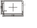
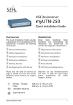
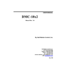
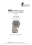
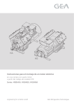
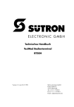
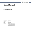
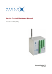
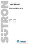
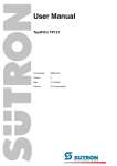
Schirmung von D-SUB-Steckverbindungen
Versorgungsspannung
Die D-SUB-Steckverbindungen müssen folgendermaßen geschirmt werden:
INSTALLATIONSANWEISUNG
INSTALLATION INSTRUCTIONS
Elektrische Daten
1390
(80860.007)
Versorgungsspannung
24 V DC (SELV entsprechend DIN EN 61131)
Restwelligkeit
Maximal 10%
Mindestspannung
19,2 V
Maximalspannung
30,2 V
Stromaufnahme
ca. 0,3 A
Prepare cables
Steckverbinder im Terminal: 3-poliger Steckverbinder Phoenix COMBICON MSTBV 2,5/
3-GF
2.
Schirmung von D-SUB-Steckverbindungen
1.
D-SUB-Steckverbinder
2.
Schirm
3.
Kabelschelle
4.
Kabel
Der Schirm muss flächig über den Kabelmantel zurückgeschlagen werden.
Durch die Befestigung mit der Kabelschelle muss gleichzeitig ein großflächiger Kontakt
vom Schirm zum Gehäuse entstehen und eine ausreichende Zugentlastung gewährleistet werden.
Connect female connector
If shielded connecting cables are used for the supply voltage, the shield should be connected to pin 1.
Steckerbelegung X1 Versorgungsspannung
Bezeichnung
Funktion
Fremdspannungsarme Erde
Symbols
2
0V
Versorgungsspannung 0 V
3
24 VDC
Versorgungsspannung 24 VDC
The symbols in this manual are used to draw your attention on notes and dangers.
Danger
This symbol refers to an operating procedure which, if not carefully followed, could result
in personal injury.
Die geeignete Buchsenleiste vom Typ Phoenix COMBICON MSTB 2,5/3-STF ist im Lieferumfang enthalten.
Sie können Kabel mit feindrähtigen Adern bis 2,5 mm² Querschnitt verwenden.
3.
Note
This symbol indicates application tips or supplementary notes.
In elektrischen Anlagen können für Menschen gefährliche Spannungen auftreten. Bei
Berührung von Spannungsführenden Teilen besteht die Gefahr eines Stromschlags!
The following symbol indicates specific danger conditions which could result in damage
to equipment or personal injury up to the death of the operator.
Plugging female connector on X1
Risk of electric shock.
Beim Anschluss des Geräts an die Versorgungsspannung gehen Sie wie folgt vor:
1.
Isolieren Sie den Außenmantel der Leitung ca. 30 mm und die Adern ca. 5 mm ab.
390
4.
All installation works at the automation system must be performed only by trained personnel (e.g. qualified electrical employees, electrical engineers)
The installation staff must have an education which entitles to interventions at the automation system.
Kabel konfektionieren
2.
Versehen Sie die Adern mit Aderendhülsen und schließen Sie die Adern an den
Steckverbinder an.
User-Mode Switch
400
Mounting
It is possible to mount the device fast and simple from the rear side. The mounting into
switchboards with a plate strength of approx. 1 to 8 mm is possible.
Buchsenleiste anschließen
Falls Sie geschirmte Anschlusskabel im Bereich der Versorgungsspannung verwenden,
dann sollten Sie die Schirmung mit Pin 1 verbinden.
3.
When installing, take care to leave a gap of at least 30 mm to ensure sufficient air circulation.
Stecken Sie die Buchsenleiste auf den Stecker X1.
English
Das nachfolgende Symbol kennzeichnet spezifische Gefahrenzustände, die zu Maschinen- und Personenschäden bis hin zum Tod des Bedieners führen können.
Gefahr durch elektrische Spannung
To ensure that the front side meets the declared degree of protection, make sure that
the seal is even with the mounting surface and the hexagonal nuts are uniformly screwed
on.
1.
2.
Push the device from in front through the mounting hole.
Screw the device with the hexagonal nuts from the accessories kit.
Connecting
Deutsch
Alle Installationsarbeiten in Verbindung mit dem Automatisierungssystem dürfen nur von
geschultem Personal ausgeführt werden (z.B. Elektrofachkräfte, Elektroingenieure).
Das Installationspersonal muss eine Ausbildung besitzen, die zu Eingriffen am Automatisierungssystem berechtigt.
Auspacken
Packen Sie alle Teile sorgfältig aus und überprüfen Sie den Inhalt auf sichtbare Transportschäden. Überprüfen Sie ebenfalls ob die Lieferung mit den Angaben auf dem Lieferschein übereinstimmt.
Wenn Sie Transportschäden oder Unstimmigkeiten feststellen, setzen Sie sich bitte unverzüglich mit unserer Verkaufsabteilung in Verbindung.
Montage
Das Gerät ermöglicht Ihnen eine schnelle und einfache Montage von der Geräterückseite. Vorzugsweise wurde hier an den Einbau in Schalttafeln mit einer Blechstärke von
ca. 1 bis 8 mm gedacht.
Beim Einbau müssen Sie umlaufend einen Freiraum von mindestens 30 mm berücksichtigen, um eine ausreichende Luftzirkulation zu gewährleisten.
Um die angegebene Schutzart zu gewährleisten müssen Sie darauf achten, dass die
Dichtung eben auf der Einbaufläche aufliegt und die Sechskantmuttern gleichmäßig angezogen sind.
Standard- und Feldbusschnittstellen
Die Anschlussbelegung der Schnittstellen finden Sie auf der Geräterückseite oder im
Produktspezifischen Anwenderhandbuch.
Betriebsartenschalter
Der Betriebsartenschalter ist auf der Rückseite des Gerätes angebracht.
Betriebsartenschalter
S1 S2 S3 S4 Betriebsart
Schieben Sie das Gerät von vorne durch den Montageausschnitt
Befestigen Sie das Gerät mit den Sechskantmuttern des Zubehörsatzes.
I
X
–
–
I
X
I
–
Standard mode with PLC (delivery state)
Standard mode without PLC
–
I
–
–
Transparent mode with start and stop code of the keys
–
–
–
I
Transparent mode without stop code of the keys
I
–
–
I
Activate download (deletes application memory) and default contrast setting
I
–
I
I
Activate upload
Legend of table:
I = Switch ON
– = Switch OFF
X = Any switch position
Shielding D-SUB Connectors
The supply voltage is connected via the connector X1.
The unit is equipped with a reverse voltage protection. If the polarity is not correct, the
unit does not operate.
This unit conforms to the safety class I. For safe operation it is necessary to use safety
extra-low voltage (SELV) in accordance with DIN EN 61131 for the supply voltage.
Electrical data
Supply voltage
24 V DC (SELV according to DIN EN 61131)
Residual ripple
10% maximum
Minimum voltage
19.2 V
Maximum voltage
30.2 V
Power consumption
Approx. 0.3 A
Connector in the terminal: 3-pin connector Phoenix COMBICON MSTBV 2,5/3-GF
Pin assignment X1 supply voltage
I
X
–
–
Standard-Mode mit SPS (Lieferzustand)
Pin
I
X
I
–
Standard-Mode ohne SPS
1
–
I
–
–
Transparent-Mode mit Start- und Stopcode der Tasten
2
0V
Supply voltage 0 V
–
–
–
I
Transparent-Mode ohne Stopcode der Tasten
3
24 VDC
Supply voltage 24 VDC
I
–
–
I
Download aktivieren (löscht den Applikationsspeicher) und Grundkontrasteinstellung
I
–
I
I
Upload aktivieren
Legende zur Tabelle:
I = Schalter ON
– = Schalter OFF
X = Schalterstellung beliebig
S1 S2 S3 S4 Function
570
Supply Voltage
Buchsenleiste aufstecken
4.
Sichern Sie die Buchsenleiste durch die Schraubverriegelung gegen herausrutschen.
Für die Schutzerdung am Gewindebolzen müssen Sie in jedem Fall eine getrennte Leitung vorsehen. Die Leitung muss einen Mindestquerschnitt von 1,5 mm² aufweisen und
so kurz wie möglich ausgeführt sein. Dadurch erhöht sich die Betriebssicherheit.
User-mode switch
You must shield the D-SUB connectors as follows:
Designation
Function
Low-noise earth
The suitable female connector Phoenix COMBICON MSTB 2,5/3-STF is supplied.
You can use cables with fine strands and a cross-section of up to 2.5mm².
1.
2.
The user-mode switch is positioned at the rear side of the device.
English
If you notice damages in transit or discrepancies, please immediately contact our sales
department.
Hinweis
Dieses Symbol kennzeichnet Anwendungsratschläge oder ergänzende Hinweise.
Zielgruppe
The pin assignment of the interfaces can be found on the rear side of the device or in
the product-specific user manual.
Unpack all parts carefully and check the contents for visible damages in transit. Also
check whether the delivery agrees with the details on the delivery note.
410
In diesem Handbuch werden Symbole verwendet, um Sie auf Hinweise und Gefahren
aufmerksam zu machen.
Gefahr
Dieses Symbol wird benutzt, wenn es durch ungenaues Befolgen oder Nichtbefolgen
von Anweisungen zu Personenschäden kommen kann.
Standard and Field Bus Interfaces
Unpacking
Deutsch
Symbole
Use the screw locking system of the female connector to prevent it from coming
loose.
A separate cable must always be provided for the protective grounding at the threaded
bolt. The cable must have a minimum diameter of 1.5 mm² and be as short as possible.
Complying with this recommendation will increase operational safety.
Target Group
TP22_IS_V1 /1-0-18.01.2002/
© Copyright by Sütron electronic GmbH
Plug the female connector on connector X1.
410
Pin
1
Fit the strands with ferrules and connect the strands to the connector.
400
Die Versorgungsspannung wird über den Steckverbinder X1 zugeführt.
Das Gerät verfügt über einen Verpolungsschutz. Bei falscher Polung wird das Gerät
nicht in Betrieb gesetzt.
Dieses Gerät ist ein Betriebsmittel der Schutzklasse I. Für einen sicheren Betrieb müssen Sie eine Schutzkleinspannung (SELV) entsprechend DIN EN 61131 für die Versorgungsspannung verwenden.
With the connection of the device to the supply voltage you proceed as follows:
1.
Strip approx. 30 mm off the outer cable sheath and approx. 5 mm off the strands.
390
Anschließen
570
Sütron electronic GmbH
Kurze Straße 29
70794 Filderstadt
Tel: ++49 7 11 / 77 09 80
Fax: ++49 7 11 / 77 09 86 0
E-Mail: [email protected]
Internet: www.suetron.de
Deutsch
Touch Panel
TP22
Hazardous voltages can exist inside electrical installations that can pose a danger to humans. Coming in contact with live parts may result in electric shock!
Shielding of D-SUB connectors
1.
D-SUB connector
2.
Shield
3.
Cable clamp
4.
Cable
The shield must be pushed back over a large surface of the cable sheath.
By fastening the cable with the cord grip you have to ensure an electrical contact of the
shield to the housing over an area as wide as possible and an appropriate strain relief.
1410
A.
B.
Montageausschnitt / Panel cutout
Frontplatte / Front panel