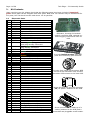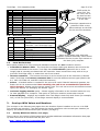
1
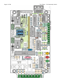
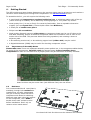
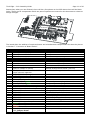
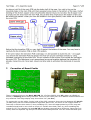
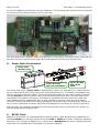
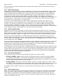
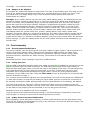
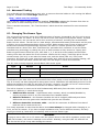
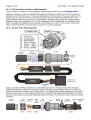
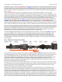
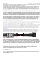
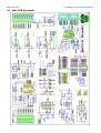
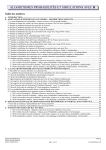
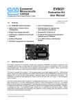
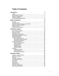
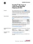
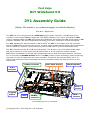
Tech Edge DIY Wideband Kit 2Y1 Assembly Guide [Note: 2Y1 model = no onboard logger, no inbuilt display] Rev 0.3 – April 2011 The 2Y1 DIY unit is a high-accuracy wideband oxygen sensor controller. The 2Y range is the successor to the original 2A DIY range that Tech Edge released in July 2003. Thousands of 2A0 (and its updated model the 2A1) have been sold worldwide. We designed the 2Y range based on 2A customer feedback. We also incorporated technology from other controllers we have developed. The 2Y1 wideband kit was introduced in March 2008. The 2Y1 is Tech Edge’s first DIY controller where we don’t offer a factory-built version. We offer other models that are factory built and backed with full warranty. However, third parties may offer the 2Y units in pre-built and tested forms. The 2Y is named from the Y in DIY (Do-It-Yourself). The 2 refers to the Tech Edge model range that has a maximum 5 Volt output (the 3 models have an 8.192 maximum output voltage). 2Y1 uses a combination of through-hole components and pre-built and tested modules. The basic 2Y1 kit includes the lambda module which is an SMT (surface mount technology) board containing the major circuitry to implement the sensor interface. An Atmel 8-bit microprocessor with a 10 million instructions per second throughput drives the lambda module and other functions on the main board. 8-Way Connector M3 x 6mm Screws Black Endplate Green Endplate Sensor Socket Logging Button LEDs 10-Way Connector Line Drawing of the 2Y controller. © Copyright 2011 Tech Edge Pty. Ltd. Australia RJ45 Sockets Page 2 of 28 Tech Edge – 2Y1 Assembly Guide Table of Contents 1.-- Basic Construction.....................................................................................................3 1.1 The 2Y1 Model.............................................................................................................3 1.2 Other 2Y Models 2Y1M, 2Y2...........................................................................................3 2.-- Kit Contents...............................................................................................................4 2.1 Electronic Parts............................................................................................................4 2.2 Miscellaneous Parts......................................................................................................5 2.3 Parts Not Included.......................................................................................................5 3.-- Overlays With Values and Numbers...........................................................................5 3.1 Overlay With Part Values (over page).............................................................................5 3.2 Overlay With Part Numbers...........................................................................................7 4.-- Getting Started..........................................................................................................8 4.1 Importance of Assembly Notes......................................................................................8 4.2 Resistors.....................................................................................................................8 4.3 Capacitors.................................................................................................................10 4.4 Semiconductors.........................................................................................................11 5.-- Assembly Notes.......................................................................................................12 5.1 Note 1 – Regulators....................................................................................................12 5.2 Note 2 – Fuse............................................................................................................12 5.3 Note 3 – DIP Sockets..................................................................................................12 5.4 Note 4 – LEDs............................................................................................................12 5.5 Note 5 – Pushbutton...................................................................................................12 5.6 Note 6 – Polarised Components...................................................................................12 5.7 Note 7 – Diodes.........................................................................................................13 5.8 Note 8 – Lambda Module.............................................................................................13 5.9 Note 9 – Molex Power Socket.......................................................................................14 5.10 Note 10 – C16 Laid Flat.............................................................................................14 6.-- The Circular 8-Pin Socket and Transition PCB..........................................................14 7.-- Correction of Board Faults.......................................................................................15 8.-- Power Cable Construction........................................................................................16 9.-- RS232 Cable.............................................................................................................16 9.1 RS232 (DB9/RJ45) Cable Schematics...........................................................................17 9.2 RS232 Cable Assembly...............................................................................................17 10.-- Preliminary 5 Volt Testing......................................................................................17 11.-- Inserting the Integrated Circuits...........................................................................18 12.-- Jumper-Shunts......................................................................................................18 12.1 J1 – Thermocouple Gain (x1 or x101).........................................................................18 12.2 J2 – WBlin- to GND Jumper-Shunt..............................................................................19 12.3 WBlin Measurement – General Considerations..............................................................19 12.4 Differential Target....................................................................................................20 12.5 Single-ended Target.................................................................................................20 12.6 Incorrectly Setting J2................................................................................................20 12.7 Avoid Large Loops....................................................................................................20 12.8 Danger of Arc Welders..............................................................................................21 13.-- Final Assembly.......................................................................................................21 13.1 Green Endplate Modification.......................................................................................21 13.2 Fitting The Case.......................................................................................................21 13.3 8-Way Green Connector Modification..........................................................................21 14.-- Advanced Testing...................................................................................................22 15.-- Changing The Sensor Type.....................................................................................22 16.-- Controller-to-Sensor Cables...................................................................................23 16.1 Controller-to-Sensor Cable Schematics.......................................................................23 16.2 DIY Controller-to-Sensor Cable Assembly....................................................................24 16.3 Circular 8-Pin Plug Assembly......................................................................................24 16.4 Harness Connector Assembly.....................................................................................25 16.5 Final Electrical Test...................................................................................................26 17.-- 2Y1 Errata..............................................................................................................26 17.1 Lambda Module 10k Thermistor Error.........................................................................27 17.2 HIN202/ST202 Ground Error – Rev 1.0b PCB...............................................................27 18.-- Main PCB Schematic...............................................................................................28 Tech Edge – 2Y1 Assembly Guide 1. Page 3 of 28 Basic Construction The 2Y1 was designed to be easily assembled by someone with prior knowledge of, and success with, the assembly of electronics. If you have no experience with electronics then we suggest you don’t try building this device as the cost of fixing things that are badly assembled can be more than buying a pre-assembled unit from us or someone else. If there is any question about your ability, then don’t tempt fate. If you need to ask us about your competency, our answer will be in the negative – if you need to ask, then you shouldn’t be building it. Note: If you build it then you fix it. Only in exceptional circumstances will Tech Edge accept DIY units for repair. If we do accept your unit for repair, we will charge you a repair cost that is commensurate with the amount of effort you have expended in building the unit and solving any problems yourself. If you built it carelessly or badly then we may not accept it and you are stuck with an expensive paperweight. If we decide to repair your DIY kit then will not charge you an unreasonable repair cost. We have had several constructors over the years who had an unrealistic expectation we would fix (for free) the mess they created through inexperience, carelessness, or by using poor tools. 1.1 The 2Y1 Model We suggest you read all of this document before beginning assembly to avoid missing important instructions. Note that some images can be zoomed in to show more detail. The 2Y series is available in several configurations. This document is about the 2Y1 model, which does not include on-board logging nor an inbuilt display. Features include: Pre-built lambda module for quick troubleshooting and reliable operation. 2 x RJ45 communications connectors (Tech Edge standard) for simultaneous display and PC logging. Suitable remote displays are available from Tech Edge, for example, LD02 (rectangular, available built or as a DIY kit), LX1 (LCD display), or LA1 (round, suits gauge mounting). 3 x K-Type thermocouple (0-50mV) inputs, intended for coarse Exhaust Gas Temperature (EGT) measurements. K-Type cold-junction-compensation (CJC), and PCB temperature via an on-board thermistor. 3 x 0-5V User inputs, intended for analog voltage measurements such as Manifold Absolute Pressure (MAP), Throttle Position Sensor (TPS), and Cylinder Head Temperature (CHT) sensors. RPM measurement (0-5 Volt input on the RPM input, possibly from an Engine Control Unit), or direct connection to a Kettering coil ignition via the COIL input. 0-5 Volt 12-bit optional differential WBlin re-programmable output for wideband aware ECUs, etc. Two additional 0-5 Volt (9.5-bit single ended) independently fully re-programmable outputs (NBsim and SVout) for narrowband simulation, driving analog displays, etc. External logging button input (used with the on-board logging option), which is useful when the unit is hard to reach. Tech Edge displays also have a button to perform a similar function. Socketed CPU and other parts for easy testing and replacement. Thermocouple inputs re-configurable as 0-5v user inputs, making up to 6 user channels. 1.2 Other 2Y Models 2Y1M, 2Y2 2Y1M: An optional 1MB SMD module and some other parts, may be purchased to upgrade the 2Y1 to the 2Y1M. This provides on-board logging memory. 2Y2: The 2Y2 model will have an on-board 4-digit display. The 2Y1 was originally designed for this option, but unavailability of one key component prevents us from offering this option. Page 4 of 28 2. Tech Edge – 2Y1 Assembly Guide Kit Contents Upon receiving your kit, please check that the following parts have been included. Unpack all parts. Some parts can be wrapped with other parts. Note that 1% resistors may be substituted for 5% parts, but 5% should not be used where 1% is specified. 2.1 Electronic Parts Qty 1 1 1 1 1 2 4 2 1 1 2 1 Part PCB WBMOD 90PCB S8PIN WIRE SPACER SCREW RJ45 2PMOL FUSE FUSEH GRN10 1 GRN8 2 1 1 1 1 1 1 1 5 2 1 1 2 1 1 1 3 1 4 3 2 6 1 5 1 4 2 2 2 5 2 1 19 1 2 7805 LEDG LEDR LEDA XTAL16 TPOT TRANZ SCHOT 4148 4007 INDUC HDR2 JUMP2 BTN2 3R31W 47R 100R 150R 1kΩ 1k5Ω 2k2Ω 10kΩ 15kΩ1W 22kΩ 30kΩ 100kΩ 180kΩ 220kΩ 15pF 1nF 3n3F 56nF 100nF 1µF 100µF Description 2Y1 main Printed Circuit Board SMD Wideband Lambda Module Transition PCB for S8PIN 20 x 20mm 8-pin circular socket (to sensor) 10cm of copper wire Nylon 9mm spacer M3 x 6mm screws RJ45 black 8-pin sockets MOLEX MiniFit 2-pin power socket 3 Amp glass Fuse Fuse Holder tags for FUSE 10-way green pluggable header – with plug already connected 8-way green pluggable header - with plug already connected LM7805 TO-220 - 5V Regulator Green 5mm LED Red 5mm LED Amber 5mm LED 16MHz low profile Crystal 10k (103) Trimpot 1.5KE-33A Tranzorb Diode 1N5822A Schottky Diode 1N4148 Signal Diode 1N4007/1N4004 Power diode 100µH Axial inductor 5 way (2mm spacing) Header 2mm Jumper-shunt 90° mount tactile push button 1 Watt 3.3 Ohm Resistor 5% 47 Ohm Resistor 5% 100 Ohm Resistor 5% 150 ohm Resistor 5% 1k Ohm Resistor 5% 1.5k Ohm Resistor 5% 2.2k Ohm Resistor 1% 10k Ohm Resistor 1 Watt 15k Ohm Resistor 1% 22k Ohm Resistor 1% 30k Ohm Resistor 1% 100k Ohm Resistor 1% 180k Ohm Resistor 1% 220k Ohm Resistor 15pF (15) Ceramic Capacitor 1nF (102) Ceramic Capacitor 3nF (332) Ceramic Capacitor 56nF (563) Green Poly Capacitor 100nF Block Monolithic Capacitor 1µF Block Monolithic Capacitor 100µF 25V Electrolytic Capacitor The PCB as it comes from the fabricator, showing the lambda module, transition PCB, optional onboard logging module and main 2Y PCB. Pre-built lambda module with SMT parts and connecting pins attached. Circular 8-pin panel mount socket (Y5) mounts to the transition PCB, and the transition PCB mounts to the main PCB. Molex MiniFit® two pin PCB connector (Y4) for power. Soldered to the PCB. Green connectors are made up of a socket (soldered to the PCB) and a removable and pluggable screw header. Tech Edge – 2Y1 Assembly Guide Qty 1 2 2 1 1 1 1 1 1 1 1 Part DIP28 DIP16 DIP14 DIP8 MEGA168 ST202 4052 6484 LM358 7414 THERM 2.2 Description 28-pin DIP socket 16-pin DIP socket 14-pin DIP socket 8-pin DIP socket Pre-Programmed 28-pin ATmega168 16-pin HIN202/ST202 RS232 driver 16-pin MC74HC4052 multiplexer 14-pin LMC6484 op-amp 8-pin LM358 op-amp 14-pin 74HC14 hex Schmitt trigger 47k @ 25°C thermistor Page 5 of 28 RJ45 socket for serial I/O. Two are used, one on the side and the other at the end of the case. Electrolytic capacitors are polarised. Refer to the white markings on the PCB for the correct orientation. Miscellaneous Parts Qty 1 Part CASE 1 ENDP1 1 ENDP2 4 4 1 1 1 SCREW WASH STICKER POWERKIT SERIALKIT Description ABS plastic case with closing screws Black endplate made from PCB laminate – has ‘Tech Edge’ logo Green endplate made from PCB laminate M3 x 6mm screws M3 spring washers Tech Edge 2Y Sticker Tech Edge Power Cable kit Tech Edge Serial Cable kit Base of the plastic case with both endplates. Detailed assembly notes should be followed for the circular 8-pin socket on the black (left) endplate. 2.3 Parts Not Included Some parts needed for a fully functional wideband controller are not included in this kit: Controller-to-Sensor cable – The Controller-to-Sensor cable goes between the unit and the connector attached to the sensor. Tech Edge has a DIY cable kit (optional 2.6m or 4.0m length) that is normally purchased with the controller. Some constructors may wish to buy a pre-built Tech Edge cable, or make their own from scratch. Harness connector – The harness connector is at the sensor end of the Controller-to-Sensor cable. Tech Edge sells harness connector kits for use with different sensor types (Bosch LSU 4.0, LSU 4.2 & LSU 4.9, and NTK L1H1/L2H2 sensors). Sensor – A lambda sensor is needed for the unit to be useful. Bosch's latest and greatest, the Bosch LSU 4.9 is recommended. Note carefully, the unit is set as standard for the Bosch LSU 4.2 sensor. Always use the correct sensor type. The unit can be set to suit different sensor types, see Section 15 “Changing The Sensor Type”. On-board logging module option – Allows logging information to be recorded inside the unit, for later playback to a computer. This option is covered in another construction manual. External display – displays are available from Tech Edge in both fully-built forms (for example, LX1) or DIY kits (LD02 DIY). A Tech Edge external display is recommended. 3. Overlays With Values and Numbers The overlays on the following two pages show the location of parts installed on the rev 1.0b PCB. Two versions are provided – one that shows the actual component value at each part location (on Page 6) and another that shows the part number (on Page 7). 3.1 Overlay With Part Values (over page) There is an on-line version of this image which includes additional embedded information that pops up when the mouse is moved across the part. See: http://wbo2.com/2y/2y1overlay.htm Page 6 of 28 Tech Edge – 2Y1 Assembly Guide Tech Edge – 2Y1 Assembly Guide 3.2 Overlay With Part Numbers Page 7 of 28 Page 8 of 28 4. Tech Edge – 2Y1 Assembly Guide Getting Started The PCB overlay and parts locator diagrams on the previous pages may be printed out and used as a reference while installing the through-hole components. The on-line version is here. To assemble the 2Y1, you will require the following tools. A good hand held temperature regulated soldering iron, or soldering station with a fine tip. (1mm chisel tip is suitable) and a wetted tip cleaning sponge or ‘curly brass’ tip cleaner. Good quality fine (1.0 mm or finer) flux cored tin/lead solder, from a reputable electronics supplier (we use Crystal 511 0.71mm 60/40 solder from Multicore). A small pair of needle-nose pliers. Philips head #2 screwdriver. Good quality diagonal cutters or side cutters so component leads may be cut off close to the PCB after soldering. Ensure all soldered component leads are trimmed to 1mm or less on the solder side of the PCB. This prevents leads from being squashed, and creating a short to adjacent pads. A de-soldering suction tool, or de-soldering copper braid (solder wick) may be useful. A Digital Multimeter (DMM) may be useful for checking component values. 4.1 Importance of Assembly Notes Please take note: There are important assembly notes spelled out, in the component tables below, for some of the components. Carefully read the relevant notes, before installing these components as often it is too late to do it properly after the part has been incorrectly installed. Bare main board before construction has commenced. Note that your board revision may be newer than (and different from) the one shown. 4.2 Resistors It is recommended the ¼ watt (that is, smallest) through-hole resistors be installed first, as taller components can get in the way when the PCB is component side down for soldering. Although most part values are written on the component, use a DMM to double check each resistor’s value before installation. Don’t rely on resistor colour bands alone! Your board will look like this once the resistors are installed. Tech Edge – 2Y1 Assembly Guide Part R2 R1 R7 R9 R14 R19 R29 R30 R31 R33 R18 R20 R22 R15 R16 R5 R23 R24 R25 R34 R36 R21 R3 R4 R6 R8 R17 R35 R26 R27 R28 R32 R10 R11 R12 R13 Resistor description 1 W 3.3 Ω (larger size!) 5% 47 Ω resistor 5% 100 Ω 5% 100 Ω 5% 100 Ω 5% 150 Ω 5% 1k Ω 5% 1k Ω 5% 1k Ω 5% 1k Ω 5% 1.5k Ω 5% 1.5k Ω 5% 1.5k Ω 5% 2.2k Ω 5% 2.2k Ω 5% 10k Ω 5% 10k Ω 5% 10k Ω 5% 10k Ω 5% 10k Ω 1% 10k Ω 1 Watt 15k Ω (larger size!) 5% 22k Ω 5% 22k Ω 5% 22k Ω 5% 22k Ω 5% 22k Ω 1% 30k Ω 1% 100k Ω 1% 100k Ω 1% 100k Ω 1% 100k Ω 1% 180k Ω 1% 180k Ω 1% 220k Ω 1% 220k Ω Page 9 of 28 4 Band Colour Code Orange Orange Gold Gold Yellow Violet Black Gold Brown Black Brown Gold Brown Black Brown Gold Brown Black Brown Gold Brown Green Brown Gold Brown Black Red Gold Brown Black Red Gold Brown Black Red Gold Brown Black Red Gold Brown Green Red Gold Brown Green Red Gold Brown Green Red Gold Red Red Red Gold Red Red Red Gold Brown Black Orange Gold Brown Black Orange Gold Brown Black Orange Gold Brown Black Orange Gold Brown Black Orange Gold Brown Black Orange Silver Brown Green Orange Gold Red Red Orange Gold Red Red Orange Gold Red Red Orange Gold Red Red Orange Gold Red Red Orange Gold Orange Black Orange Silver Brown Black Yellow Silver Brown Black Yellow Silver Brown Black Yellow Silver Brown Black Yellow Silver Brown Grey Yellow Silver Brown Grey Yellow Silver Red Red Yellow Silver Red Red Yellow Silver 5 Band Colour Code Orange Orange Black Silver Gold Yellow Violet Black Gold Gold Brown Black Black Black Gold Brown Black Black Black Gold Brown Black Black Black Gold Brown Green Black Black Gold Brown Black Black Brown Gold Brown Black Black Brown Gold Brown Black Black Brown Gold Brown Black Black Brown Gold Brown Green Black Brown Gold Brown Green Black Brown Gold Brown Green Black Brown Gold Red Red Black Brown Gold Red Red Black Brown Gold Brown Black Black Red Gold Brown Black Black Red Gold Brown Black Black Red Gold Brown Black Black Red Gold Brown Black Black Red Gold Brown Black Black Red Silver Brown Green Black Red Gold Red Red Black Red Gold Red Red Black Red Gold Red Red Black Red Gold Red Red Black Red Gold Red Red Black Red Gold Orange Black Black Red Silver Brown Black Black Orange Silver Brown Black Black Orange Silver Brown Black Black Orange Silver Brown Black Black Orange Silver Brown Grey Black Orange Silver Brown Grey Black Orange Silver Red Red Black Orange Silver Red Red Black Orange Silver Note the larger 1 W resistors. Don't confuse these with the inductor L1. Page 10 of 28 4.3 Tech Edge – 2Y1 Assembly Guide Capacitors The capacitors are now added. The largest (two electrolytics) go last. Part C12 C13 C25 C32 C33 C34 C37 C29 C30 C31 C2 C3 C8 C9 C11 C14 C15 C16 C18 C19 C20 C21 C22 C23 C24 C26 C27 C28 C35 C17 C1 C4 Description 15pF Ceramic Disc Capacitor 15pF 1nF Ceramic Disc Capacitor 1nF 1nF 1nF 1nF 3.3nF Ceramic Disc Capacitor 3.3nF 56nF Green Poly Capacitor 100nF yellow or blue, Block Monolithic Capacitor 100nF 100nF 100nF 100nF 100nF 100nF 100nF Lay flat, see Note 10 100nF 100nF 100nF 100nF See Section 7 Correction of Board Faults 100nF – C22 is not marked on the PCB, it is to the left of U5 (HIN202/ST202) 100nF 100nF 100nF 100nF 100nF 100nF 1µF blue, Block Monolithic Capacitor 100µF 25V Electrolytic Capacitor 100µF Marked As 15 15 102 102 102 102 102 332 332 563 104 104 104 104 104 104 104 104 104 104 104 104 104 104 104 104 104 104 104 105 100uF25v Note 6 100uF25v Note 6 4.4 Semiconductors Next the semiconductor components and miscellaneous parts are installed. These include diodes, the inductor (looks like a large resistor), the crystal, LEDs etc. Tech Edge – 2Y1 Assembly Guide Page 11 of 28 Notice that, when you are finished, there will be a few places on the PCB where there will be blank holes. These are for components which are part of options not covered in this document or relate to design changes. The board after the addition of semiconductors and miscellaneous components. See also the picture in Section 7 “Correction of Board Faults”. Part D1 D2 D3 D6 D4 D5 D7 D8 D9 L1 T1 U10 U12 VR1 X1 Y2 Y3 Y4 Y6,Y7 pin U1 U3 U5 U6 U8 U9 F1 LED1 LED2 LED3 J1 J2 Description 1N5822A Schottky Diode 1.5KE-33A Tranzorb® Diode 1N4007 Power Diode 1N4007 1N4148 Signal Diode 1N4148 1N4148 1N4148 1N4148 100uH Axial Inductor (may be 100uH or 330uH) 47k @ 25°C Thermistor – looks like a multi-coloured capacitor LM7805 TO-220 5v regulator LM7805 TO-220 5v regulator 10k Trimpot 16.000 MHz Crystal 8-way 5.08mm green connector 10-way 3.51mm green connector 2-pin Molex MiniFit® power socket 24-pin 2.54mm black header (Female) 1-pin 2.54mm black header (Female) 28-pin DIP socket 16-pin DIP socket 16-pin DIP socket 8-pin DIP socket 14-pin DIP socket 14-pin DIP socket Fuse holders and 3 Amp fuse Green 5mm LED Red 5mm LED Amber 5mm LED 2mm 3-pin header, with jumper-shunt 2mm 2-pin header, Notes Note 7 Note 7 Note 7 Note 7 Installed on side, Note 7 Installed on end, Note 7 Installed on end, Note 7 Installed on end, Note 7 Installed on end, Note 7 Brown Black Brown Silver (100 uH) Orange Orange Brown Silver (330 uH) Yellow Violet Orange Gold Note 1 Note 1 Marked 103 Temporarily remove plug with tunnel connectors Temporarily remove plug with tunnel connectors Note 9 For the lambda module, Note 8 For the lambda module, Note 8 ATmega168-20 CPU, Note 3 74HC4052 MUX, Note 3 ST202 RS232 driver, Note 3 & Section 7 LM358 Op-Amp, Note 3 MC33204 Op-Amp, Note 3 74HC14 Schmitt trigger, Note 3 Note 2 Note 4 Note 4 Note 4 Put jumper on x101 position Install jumper Page 12 of 28 Part Y1A Y1B BTN 5. Description with jumper-shunt RJ45-style socket RJ45-style socket Tactile switch 90° (push button) Tech Edge – 2Y1 Assembly Guide Notes Note 5 Assembly Notes 5.1 Note 1 – Regulators The 5V LM7805 regulators should have their leads bent at 90° and mounted such that the hole in the TO-220 package lines up with the hole in the PCB. Later, for each regulator, a screw will be installed from the solder side of the PCB, into a nylon spacer. The lambda module mounts on the other side of the spacers. 5.2 Note 2 – Fuse The two fuse holders each have a small end tab that may prevent the fuse from being inserted if they are the wrong way around. Also, some longer fuses require that the end tabs are bent out slightly to allow a little more length for the fuse. Insert the fuse holders into the PCB holes, then insert the fuse into the holders. Check to see if the end tabs need to be bent out. Bend the tabs as necessary before soldering the fuse holders in. 5.3 Note 3 – DIP Sockets Be careful to insert the DIP sockets so the notched end matches the legend on the PCB. This will help prevent you or someone else inserting the matching IC the wrong way around. 5.4 Note 4 – LEDs LEDs are polarised. Make sure they are mounted the right way around. They have a ridge running around the circumference of the main body, and there is a flat section on this ridge, which indicates the Cathode. Match the flat to the PCB legend. The three LEDs are mounted (with correct polarity) then bent. The base of each LED should be 6mm from the PCB. Then they are bent over by 90° so as to ultimately protrude slightly from the holes in the lower casing – Refer to images. The tips of the LEDs should project about 2mm further than the face of the adjacent green 10-way connector. Mount LED 6mm PCB Then BEND 90° PCB 5.5 Note 5 – Pushbutton 7mm The 90° PCB mounted tactile switch (autocal and logging button) must have its legs straightened slightly so that it will sit flat on the PCB. The push button should protrude very slightly through the hole in the case when the PCB is eventually assembled into the case. We suggest you test assemble the case with the button lightly soldered in before final soldering. The button must operate freely when the case is finally assembled. 5.6 Note 6 – Polarised Components Some components are polarised, and must be installed in the correct orientation to work correctly and to avoid hazards (e.g. exploding electrolytic capacitors). It is absolutely essential to be able to recognise directional markings on the casings of all polarised components. Electrolytic capacitors are marked with a negative stripe, which should be matched with the stripe on the PCB legend. Bend the legs on the electrolytic capacitors at 90°, and test fit and check before soldering, The PCB legend also has a positive symbol to mark the opposite pin to the stripe. Electrolytic capacitor. A blob of epoxy or hot melt glue may be applied to the bent-over electrolytic capacitors, to prevent movement and vibrations causing solder mounting points to fracture. Tech Edge – 2Y1 Assembly Guide Page 13 of 28 5.7 Note 7 – Diodes Diodes are marked with a stripe on the PCB legend, which should be matched to the end with the black or white stripe on the diode body (cathode). Some small diodes are mounted on end, with a ring marking on the PCB denoting the cathode, and a bar pointing toward the other pad. The diode should be installed with the black or white stripe (cathode) closest to the ringed pad. 5.8 Note 8 – Lambda Module The lambda module has 25 pins in total. The module has a 24-pin male header to connect it to the 2Y1 main board. This male header plugs into Y6 and Y7, using the 24-pin 2.54mm black header (Female), which is soldered to the main PCB. There is also a 1-pin male header fitted next to the leftmost pin on the lambda module, when looking at it as shown on the image on the right below. This header is the 25th pin. An image of the top of a lambda module is shown at below left. Note that the electrolytic capacitors (silver “cans” on the bottom of the module) are on the face of the PCB opposite the surface mount components, and the male header pins also protrude from this face. Assemble the 24-pin female header on the main PCB first. Make sure that the header is at a right angle to the main PCB, not leaning over to the left or right. The 25th pin plugs into a 1-pin 2.54mm black header (Female) which is located next to pin 1 of the unused U2. Look at the underside of the lambda module for a better idea of where the 25th pin is. The 1-pin header was made by cutting it off a long header strip. Getting this header in the right position is easy, provided you go about it correctly. lambda module M3 x 6mm screw 24-pin header 25th pin goes here 9mm Nylon spacer TO-220 regulator M3 x 6mm screw 2 x M3 star washers After the 24-pin header is soldered in, assemble the plastic spacers on to regulators (U10 and U12) – see the diagram above in this note. There are two M3 x 6mm screws, installed from underneath the main PCB, which go through holes in the regulator tabs. At each screw, put the screw through the PCB and the regulator tab (which should be nicely aligned, in accordance with Note 1). Then put two star washers on, then tighten the screw into the plastic spacer. Make sure that C16 is laid flat (see Note 10). Put the 1-pin header in position next to pin 1 of U2, but do not solder it yet. Plug in the lambda module. Making sure it mates correctly with the 24-pin header, plus the 1-position Page 14 of 28 Tech Edge – 2Y1 Assembly Guide header for the 25th pin. Install the M3 x 6mm screws for the two corners of the lambda module with holes. Now the lambda module, with the 25th pin, is positioned correctly. Solder the 25th pin. By undoing the top two M3 screws, unplug the lambda module. It is recommended that you remove the lambda module for now, until after initial testing (see the “Preliminary 5 Volt Testing” section below). 5.9 Note 9 – Molex Power Socket The 2-pin Molex socket, for power & ground, lines up with a cutout in the black endplate. 5.10 Note 10 – C16 Laid Flat Capacitor C16 ends up under the lambda module, next to the unused 8-pin U2. C16, if left standing up (as usual), can be too close to a jumper-shunt on the lambda module. To avoid this, lay C16 flat on the main PCB by bending it over, in the direction of U2. 6. The Circular 8-Pin Socket and Transition PCB The circular 8-pin socket is on the black endplate and the Controller-to-Sensor cable plugs into it. The small (20mm x 20mm) transition PCB is soldered to the other side of the circular 8-pin socket, then eight small copper wires join it to the main PCB. The order of assembly noted below is critical for correct and long-term reliable operation. Take very careful note of the following instructions. We have found many people who have not paid attention have soldered parts that are difficult or impossible to remove without their destruction. Tech Edge uses the convention that a connector which is part of a panel is called a socket. The circular 8-pin metal bodied socket is first inserted through the hole in the black endplate (made from PCB material). The keyway on the circular socket must be aligned as shown below. The lock washer and nut should be attached and tightened so that the socket does not rotate. Don’t overtighten and destroy the thread. Keyway Refer to the images below. Note that the finished picture is of the main PCB in an upside down position compared to the line diagrams. The transition PCB should be soldered to the sensor socket, but it’s very important that a small gap (around 1mm) is left between the housing of the sensor socket and the surface of the transition PCB. As there is sometimes a little play in the end of the socket, any movement against the PCB can cause the thin solder resist to be abraded away and, in time, cause a short circuit, and possibly damage the unit or the sensor. The easiest way to ensure the necessary small gap is as follows: Put the socket, assembled onto the black endplate, with the solder-side pins facing straight up. Get some bare copper wire (supplied in the kit) and bend it into a hairpin shape (like a tall U) then lay it flat between the pins of the socket. Then lay the transition PCB, in the correct orientation (see diagram below) on the pins. Then solder one pin. Pull out the copper wire. Check that there is a nice even small gap. Solder the remainder of the pins. The transition PCB should have 8 short lengths (1cm) of copper wire soldered on, so they protrude from the transition PCB side with the text, opposite the socket. The easiest way to do this is to bend some copper wire into four hairpins about 20mm by 5mm. Then insert each hairpin into two adjacent holes in the transition PCB, then solder. Cut the protruding wires to length, thereby discarding the bent part of the hairpin. On the socket side of the transition PCB, cut the wire off nearly flush. You end up with eight short wires protruding out. Bend the wire as shown, and insert into the main PCB, the endplate should fit nicely over the RJ45 socket (which is already soldered to the main PCB). Carefully filing the bottom right corner of the endplate, so that it is no longer sharp, will help the fitting of the main PCB. The face of the RJ45 socket should be flush with the face of the endplate. This positioning is essential so that, later on, the case can be assembled correctly. Check There is a board fault on the Rev 1.0b PCB. Pin 15 of the RS232 chip (U5, either an HIN202 or ST202) is floating rather than grounded. This error will cause poor or no RS232 communication and any attached Tech Edge display may show show “nd” (no data). To correct this, on the solder (under) side of the PCB, connect a short wire link between U5 pin-13 (a GND point) and the nearest capacitor-leg/solder-pad of C21, as shown in the images below. A neat way to achieve this result is, when installing C21, leave the appropriate leg of C21 long and unsoldered and bend it over close to U5 pin-13. Solder them both, later on, when installing the socket for U5. The capacitor leg and pin-15 are already connected by a PCB trace. Once this fix is made, both the capacitor leg and pin 15 should be at GND potential. You can check that both pins Page 16 of 28 Tech Edge – 2Y1 Assembly Guide 13 and 15 of U5 are grounded by using an ohmmeter. The mounting holes at each corner of the PCB are handy ground reference points to use for this test. The main PCB is now complete, ready for preliminary 5 Volt testing, see picture above. Note that the ICs have not been inserted at this stage. Note that capacitor C16 has been laid over flat. 8. Power Cable Construction + Molex clear MiniFit® plug ― Crimp & Solder. Note tab orientation Figure-8 Cable with white flash The heavy duty figure-8 power cable is assembled as shown. The terminals are crimped onto the figure-8 cable with a pair of long nose pliers, and soldered securely. To maintain compatibility with the way we make production cables, ensure the white stripe/flash on the figure-8 cable is inserted into the bottom of the plug (that is, away from the Molex plug’s lock-tab). The cable without the stripe/flash is the positive connection, and should be marked at the other end of the cable with some red heat shrink, red alligator clip, or other method of ensuring it only goes to a positive terminal. Circuitry prevents the 2Y1 being damaged if connected in the reverse polarity, but do not rely on this in case there is another fault that could damage the unit when it's reverse connected! Note carefully, the rotational orientation of the terminals when they go into the plug is critical, so that the small locking tangs will work. 9. RS232 Cable 2Y1 can communicate via a standard RS232 serial connection. Most PCs and many laptops have a standard RS232 port, typically referred to as the COM1 or COM2 port. Newer computers, laptops in particular, may not have an RS232 port, in which case a USB-RS232 converter or dongle should be used (these are available from Tech Edge or general PC suppliers). Tech Edge – 2Y1 Assembly Guide 9.1 Page 17 of 28 RS232 (DB9/RJ45) Cable Schematics GROUND Pin 5 (shield) cover with heatshrink PC-Tx Pin 3 GND PC-Rx Pin 2 P1 9.2 RS232 Cable Assembly te DB9 Serial 1. 2. 3. 4. 5. 6. 7. 8. 9. PC-Rx (WHITE) PC-Tx (RED) GROUND (SHIELD) - 3 PC-Tx 2 PC-Rx te RJ45 Serial 5 GND (shield) 1 1 1. 2. 3. 4. 5. 6. 7. 8. WBo2-Rx (RED) WBo2-Tx (WHITE) GROUND (SHIELD) - A partially constructed RS232 cable is supplied – it has just the RJ45 plug crimped on one end. The supplied DB9-S (female DB9 connector) must be soldered according to the diagram above. The lower diagram shows the DB9 connector viewed from the solder side. The white wire goes to pin 2 on the DB9 connector. Red goes to pin 3. Twist the shield, tin it and put a small piece of 1.5mm heatshrink over it to prevent any stray strands of wire touching any other terminal. The shield (Ground) goes to pin 5. Notice that the red wire PC-Tx (DB9-3) goes to WBo2-Rx (RJ45-2), and the white wire WBo2-Tx (RJ45-3) goes to PC-Rx (DB9-2). This is because Tx (an output) must go to an input (Rx). Both cable ends (PC and WBo2) have a Tx and Rx circuit so that data can flow in both directions at the same time. The GND (Ground) is a common return path for both of these Tx/Rx circuits. The backshell (supplied as parts in a small plastic bag) includes a cable strain relief clamp. You do not want any tension placed on the cable causing tension on the soldered joints. The cable is a little too small in diameter, so wrap it with adhesive tape, where the strain relief clamp will go, to build up the diameter. Install the strain relief clamp. Assemble the backshell halves with the screws and nuts supplied. The RS232 cable is now finished. 10. Preliminary 5 Volt Testing Once all the components have been installed as described above, some tests should be carried out before installing the CPU and other integrated circuits. This ensures the 5 volt regulators and other components are working correctly and should not damage any ICs inserted later. Remove the lambda module if it is already installed. No ICs (apart from the regulators) should be installed and no sensor should be connected. Power is now applied to the unit via the Molex power cable. Power is preferably supplied from a current-limited bench power supply (which must be capable of a sustained delivery of 3 Amps while maintaining a 12 Volt terminal voltage). An alternative source is a fully charged automotive battery (in good condition), but as these are not current limited, be aware of the hazards of high currents causing local heating and injury. Do NOT use a battery charger for testing. A proper bench power supply (or real fully charged battery) should be found. Battery chargers usually have no current smoothing and produce an unfiltered AC waveform that will cause improper operation, and at worst may damage the wideband unit. An old PC power supply is a good source of regulated 12V DC; 12V is on the yellow wires, GND on the black. Page 18 of 28 Tech Edge – 2Y1 Assembly Guide +5 Volts Battery Volts +5 Volts Ground With power applied, but with no sensor connected yet, the wideband unit should have the green power LED brightly illuminated, but the other LEDs should not be illuminated. Using a good quality voltmeter or digital multimeter, check both of the 5 Volt rails, using the tab of one of the 5 Volt regulators as a Ground reference. Refer to the diagram above, in this section, for where to place your probes. If the voltage measured is not between 4.9 and 5.1 Volts, then there is a problem that must be corrected before going on any further. 11. Inserting the Integrated Circuits Insert the integrated circuits, paying attention to static prevention. Refer to the illustration “Overlay With Part Numbers” in Section 3.2 for guidance. Pay particular attention to which way around the ICs are plugged in. Notice that there is a notch drawn on the PCB, at the end where pin 1 of the IC will be. There is also a notch on the IC sockets. There is another notch on the ICs. All these notches should line up. The lambda module should be re-installed, by plugging it in, and securing it with the screws. 12. Jumper-Shunts J2 – WBlin GND J1 – Thermocouple Gain x101 x1 W1, W2, W3 Not installed X101 for thermocouple, X1 for 5 Volt input 12.1 J1 – Thermocouple Gain (x1 or x101) This jumper sets the gain of an amplifier, and thereby switches whether the three inputs (T1, T2 & T3, on the 8-way green connector) are used for thermocouples or 0-5 Volt inputs. Set the jumper in the x101 position for thermocouple operation, or in the x1 position for 0-5 Volt inputs. Standard is the x101 position. Tech Edge – 2Y1 Assembly Guide Page 19 of 28 12.2 J2 – WBlin- to GND Jumper-Shunt The J2 jumper simply joins the WBlin- input to its adjacent GND pin on the unit. As standard, it is on. Alas, deciding whether J2 should be on or off is somewhat technical. Please see the following few sections for details. Note that the effect of the J2 jumper can be reproduced by wiring WBlin- and GND together with a short piece of wire, on the 10-way green connector. This obviates opening the case to access J2 (but make sure J2 is off when you need it off). The jumper and the short do exactly the same thing – to avoid confusion, do not use both. 12.3 WBlin Measurement – General Considerations WBlin is the main output voltage of the wideband unit, derived from the sensor. WBlin is a voltage level representing lambda/AFR. WBlin may be used by an ECU, analog data logger, or other device (we call it the target in the following paragraphs). The WBlin output voltage is a single-ended output as standard (J2 jumper ON), but it may also be set up as a differential output. Most devices produce single-ended outputs, for example, the 2Y1's NBsim and SVout are single-ended. WBlin may be converted to a differential output and this is described below, along with the reasons why it should be used as a differential output. The problem facing the user of the wideband unit, is how to get the WBlin output accurately from the wideband unit to the target, without having the signal corrupted by noise, hum or interference, which would destroy its hard-won accuracy. The target could be a device with its own GND connection, such as a logger. Now we have two different pieces of equipment with different ground voltages. Ground voltage differences can be caused by induced voltages, or currents in ground wires. Both of these are unavoidable, so any two different pieces of equipment will always have some difference in ground voltage. What to do? Answer, the same as has been used in professional audio and telephony for many years, cancel out the ground voltage difference and thereby extract the wanted signal (WBlin in our case). The ideal situation is to have a differential-input target being driven by the unit's WBlin+ and GND operating as a single-ended output. The interference is cancelled out in the target, since the target measures only the voltage difference between the two output pins (WBlin+ and GND). It is not acceptable to have a single-ended output driving a single-ended input because then there is then no rejection of the ground voltage differences. However, it sometimes happens that someone has an existing piece of equipment (the target), which happens to have a single-ended input. What to do then? Answer, cancel out the ground voltage differences in the wideband unit. That is the purpose of the WBlin- input. That gives the unit a differential output. The general rule is: Single-ended output to differential input = OK (recommended) Single-ended output to single-ended input = Not OK Differential output to single-ended input = OK (sort of) Differential output to differential input = Not OK 2Y1's 10-way green connector has two pins that carry the name WBlin; one is WBlin+ (the WBlin output voltage representing lambda/AFR) and the other is WBlin- (which is a ground reference input for WBlin+). The output voltage on WBlin+ is the sum of WBlin and the input voltage on Wblin-. The voltage on WBlin- is measured relative to GND on the wideband unit. For more detail on WBlin considerations please see: http://wbo2.com/sw/wblinout.htm The first thing to do, is to decide whether you have a differential or a single-ended target. If the target has no separate earth connection of its own, then it must be differential. It is using the GND pin on the unit as its ground reference point. For example, an ordinary battery-operated digital multimeter is differential. A mains-operated target with a double-insulated power supply is also differential. However, if the target does have its own separate earth connection, then you need to look harder at the target to see whether it has a differential input or not. The sign of something being a single-ended input is one of the input terminals is a ground pin, connected to the case. You can check that with a multimeter. For example, a conventional oscilloscope with an earthed case and a BNC input would be a single-ended input. Conversely, some oscilloscopes have differential plugins, with a true differential input. However, such oscilloscopes are rather rare. It can be difficult to Page 20 of 28 Tech Edge – 2Y1 Assembly Guide decide whether your target is differential or single-ended. Seek help from an electronics expert if you are not sure. 12.4 Differential Target Suppose you conclude that your target is differential. The target must be differential, sensitive only to the voltage difference between its input terminals and ignore any common-mode voltages. Nor must the target inject any differential currents into either of its input terminals. A well-designed target will do all that. The unit stays as standard, with a single-ended output. J2 stays on (or an external link is provided between the WBlin- and GND terminals). Both WBlin+ and GND are connected to the two input terminals of the target. For example, on a multimeter connect WBlin+ to the multimeter's +VDC terminal, and connect GND to the multimeter's COM (common) terminal. Two wires are to be connected – it is that simple. If you have a true differential target which is also independently earthed, then watch out for excessive common mode voltages, which could overload your target's common-mode rejection circuitry. For example, suppose the unit was installed in a car with the WBlin signal going to an external earthed, oscilloscope or logger. There is nothing to stop the body of the car “floating” at some high voltage. Provide an earthing wire for the car body to prevent this problem. Then common mode voltages will be a small fraction of a volt and will not cause trouble. 12.5 Single-ended Target Suppose you decide that your target is single-ended. Now things get a little bit tricky. Joining the GND pin on the unit to the GND terminal on the target would be a mistake, because they have both been earthed by separate means. You can test for that by checking for continuity between the two GND points with WBlin+, WBlin- and GND on the 10-way green connector otherwise disconnected. Convert the single-ended WBlin to a differential output, by taking J2 off (and removing any link between WBlin- and GND) on the unit. (Hint: hang the little jumper off one pin so that you do not lose it.) Connect the the WBlin- input to the GND terminal of the target. Connect the WBlin+ output to the voltage input of the target. Then the difference between the ground potentials, of the wideband unit and the target, is cancelled out by the circuitry inside the wideband unit. For complex electronic reasons (which will not be explained here), this technique only works “reasonably well”. It works a lot better than getting it wrong, but a true differential input on the target is the best. The wideband unit can only cope with a voltage difference between the grounds of at most two volts at any instant in time. Since both the unit and the target are independently earthed, then excessive voltage differences between the unit and the target, should be impossible. However, be careful to preserve the independent earthing. Pay attention to the “loop area” enclosed by the independent earthing and take reasonable steps to minimise it. 12.6 Incorrectly Setting J2 It is important to note that incorrectly setting this jumper can result in either: Excessive WBlin+ noise (mostly heater switching transients at 30Hz) occurring on WBlin+. This happens when WBlin- is connected to the GND pin, but ground on the wideband unit is different to ground on the target, then using a single-ended target. This problem can be caused by the jumper being ON when it should be OFF. Floating WBlin-, which then causes the WBlin+ output to exceed 5 Volts or go below 0 Volts. The Wblin- input should always be connected to some ground, either GND on the unit, or ground on the target. This problem can be caused when the jumper is OFF when it should be ON. As standard, the J2 jumper is ON, but you know what kind of target you have, so you make the decision. 12.7 Avoid Large Loops Make sure your two wires joining the unit to the target do not include any significant area between them. This would create a loop of wire capable of picking up interference. It is best to have both wires together and shielded. Conventional shielded microphone audio cable will do the job very nicely. If the target has its own earth, connect the shield to a GND point on the target. Otherwise, connect it to GND on the unit. Tech Edge – 2Y1 Assembly Guide Page 21 of 28 12.8 Danger of Arc Welders Arc welders are a particular danger to earth wires. It is easy to accidentally get a very large current from an arc welder going through some earth wire, thereby causing it to “blow” like a fuse. Then your earth wire is no longer doing its job. Then all sorts of safety hazards and electronic malfunctions can happen. Example: An arc welder was set up next to a heavy metal welding bench. The welding bench was earthed by having a small grinder bolted to it. The work clamp of the welder was attached to the bench. The welder, being reasonably large, had its own heavy earth wire. One day, the welding bench was found to be no longer earthed. Inspection revealed that the grinder's earth wire was blown. How did that happen? Answer: Someone had left the electrode holder on the top of the welder, which was metal. The welding rod had touched the metal case. The current flow was as follows: welder electrode terminal, electrode holder, welding rod, welder case, welder earth wire, switchboard earth link, grinder earth wire, grinder, welding bench, work clamp, welder work terminal. The grinder earth wire, being the weakest link, then blew. Notice that the grinder and the welder kept right on working and nothing was obviously wrong. The solution was (1) Replace the grinder power cable, (2) provide an insulating platform on the top of the welder where the electrode holder could go, (3) give the welding bench its own heavy earth wire back to the switchboard, (4) educate staff. 13. Final Assembly 13.1 Green Endplate Modification The green endplate, with the 8-way green connector, labelled “Logger Inputs”, has a terminal on it which is incorrectly marked “RPM”. That terminal is actually a GND terminal, the same as its neighbouring terminal, which is marked with the international “ground” symbol. Using a black permanent marker, obliterate the “RPM” marking. The terminal is now marked with a black rectangle. Remember that the “black rectangle” terminal is a GND terminal. 13.2 Fitting The Case Now the PCB is assembled into the plastic case. Make sure the green endplate is slid over the 8-way green connector before the PCB is inserted. The PCB should be inserted at an angle initially, to allow the LEDs and logger button to fit into the holes in the bottom of the case. The mounting holes in the PCB should line up nicely with the screw holes in the case. If that does not occur, then difficulties will be experienced operating the logger button. Correct any such problems before continuing. Fix the PCB to the case, using four M3 x 6mm screws. At this point the unit should look like the illustration on page 1. The 4 rubber feet included are optional, but recommended if the unit is to be placed on a dashboard or other hard surface, to stop the unit sliding off. Each rubber foot has a circular die-cut around it. By carefully bending the rubber backing sheet, the foot (with adhesive on the bottom) will detach. The case lid is placed on, and the 4 x 20mm countersunk case screws are installed. Finally the sticker should be carefully applied to the top of the case. Make sure that the descriptions of each pin on the label line up properly with the terminals on the 10-way green connector. Assembly of your 2Y1 wideband unit is now complete. If you are going to do advanced electronic testing, it will be necessary to temporarily remove the case lid again, so as to give you access to internal points of the circuit. 13.3 8-Way Green Connector Modification When plugging in the 8-way green connector, it will be found that there are two little plastic “nibs” which hit the endplate when attempting to plug in the connector. Cut them off with side-cutters. The connector will then plug in normally. Page 22 of 28 Tech Edge – 2Y1 Assembly Guide 14. Advanced Testing It is preferable on first powering up your unit, to connect the serial cable to a PC running the WButil program, available from Tech Edge. Please see: http://wbo2.com/sw/util.htm Check that the latest firmware has been installed. Tech Edge updates the firmware from time to time, and it is worth checking to see if new firmware has been released. There is another document, “2Y1 Test Procedure” which should be consulted for more advanced testing. 15. Changing The Sensor Type The unit must be correctly set to drive different types of sensor. As standard, the 2Y1 unit is set to drive a Bosch LSU 4.2 sensor. In 2010, the LSU 4.2 was Tech Edge's most popular sensor, by sales volume. However, the unit can be set to drive a variety of sensors, including the recommended Bosch LSU 4.9 sensor. The LSU 4.9 is a later design, has somewhat better performance and its price is falling, due to increasing popularity driving volume. Older sensors tend to have a higher price because as manufacturing technology improves, the same or a better product can usually be manufactured at a lower cost. Also, manufacturers' persuade their customers to use the latest manufacturing technology by raising the price of older sensors as they become a "legacy part". Bosch oxygen sensors follow this rule, with older 1, 2, 3 and 4-wire narrowband sensors often costing more than the latest LSU 5-wire sensors. Within the LSU range, Tech Edge prices for the newest sensor (LSU 4.9) is now also the lowest cost, and the oldest (LSU 4.0) is the most expensive. Of course the newer sensors are also better and, with the correct controller setting, will give more accurate and faster results and may even last longer in harsh environments! The 2Y1 unit currently supports several Bosch LSU sensor types: Type Models Notes LSU 4.9 17123/17025 currently the best sensor to use LSU 4.2 7200/7057 used by us and others for the last 8 years LSU 4.0 6066 was one of Bosch's first LSU sensors. The LSU 4.0 and LSU 4.2 are similar internally and only differ in their free-air pump current specifications (the older LSU 4.0 requires about 20% more pump current compared to the LSU 4.2). The 2Y circuitry has been designed so that proper free-air calibration will adequately account for the differences between the LSU 4.0 and LSU 4.2 sensors. However, the LSU 4.0 and 4.2 sensors have different connectors, so a different Controller-to-Sensor cable is needed. The LSU 4.9 sensor is newer and is built fundamentally differently from the older 4.0/4.2 sensors. Because it's different, it needs three things: 1. Additional bias current – implemented with a resistor, which is enabled/disabled by moving a jumper which is on the underside of the lambda module. 2. Different firmware – this firmware handles the LSU 4.9 slightly differently and these differences were too great to be handled with just the one firmware. 3. Different Controller-to-Sensor cable – the LSU 4.9 connector is different from that of both the LSU 4.0 and the LSU 4.2. It is vitally important to note that the above items must always be changed when changing to, or from, an LSU 4.9 sensor. If you have multiple wideband units, set for different sensors, and they might get mixed up, label each unit carefully with its correct sensor type. WARNING Trying to use an LSU 4.0 or 4.2 sensor with the jumper-shunt in the LSU 4.9 position, and/or with LSU 4.9 firmware, will result in damage to the sensor. Similarly, using the LSU 4.9 with the 2Y1 set for the LSU 4.0/4.2 may also damage the sensor. Tech Edge – 2Y1 Assembly Guide Page 23 of 28 The jumpers for sensor type are on the underside of the lambda module, but the markings for jumper position are on the top, in tiny white lettering. Rather than describe here how to change the jumper settings and the firmware, you should go to the on-line 2Y User Manual page at: http://wbo2.com/2y/userman.htm#sensor where full details are presented. The firmware can be found at: http://wbo2.com/sw/hxf.htm In accordance with the 2Y user manual, the NTK L1H1 UEGO sensor is not supported. There is no HXF file (that is, there is no firmware) available for the 2Y series to drive this NTK sensor. Make sure the NTK/LSU jumper is in the correct LSU position. 16. Controller-to-Sensor Cables The 6-core Controller-to-Sensor cable, goes between the wideband unit and the sensor plug, which is provided as part of the sensor. The cable has two ends. The circular 8-pin plug end plugs into the unit (or controller). The harness connector end plugs into the connector attached to the sensor. The Controller-to-Sensor cable has a fibreglass sheath to protect it from mechanical damage and damage by hot objects. Please Note: These cables are available pre-built or as DIY cables, from Tech Edge. Correctly assembling a DIY Controller-to-Sensor cable is reasonably difficult and should only be attempted by experienced constructors. Read the assembly instructions given in this document most carefully before you begin. Consider the possibility of buying a pre-built cable. 16.1 Controller-to-Sensor Cable Schematics Tech Edge – 2Y1 Assembly Guide Page 25 of 28 Take the end of the Controller-to-Sensor cable where a small piece of cable is projecting clear of the fibreglass sheath. Thread a 20mm length of 10mm heatshrink over the fibreglass sheath, and then put the cable through the body. Notice that the sheath will not also go through. Pull some cable out, that is move the body and sheath back out of the way. Put a 25mm-long piece of 6mm heatshrink on the cable. Next, strip 15mm of the cable, and separate the wires. Consult the diagrams in the section “Controller-to-Sensor Cable Schematics” and carefully identify which is the correct diagram for your cable. You may like to use a highlighter to identify the correct diagram. It is easy to accidentally use the wrong diagram, otherwise. Put the shield, twisted to make it manageable, in the centre, with the other wires arranged in the correct order around the shield. Strip and tin the individual wires. A good-quality wire stripper will be useful. Tin the terminals of the plug. Place the clear insulator over the cable, then a 6mm length of 3mm heatshrink over each large wire, and a 6mm length of 1.5mm heatshrink over each of the smaller wires. Put around 12mm of 1.5mm heatshrink over the shield. Solder the shield on to the correct terminal (pin). That is usually pin 8, the centre pin, except in the case of the NTK L1H1 sensor; then, use pin 2. Solder the other wires each to the correct pin. Once the wires are soldered, pull the heatshrink up over the soldered joints, then shrink them with a heat gun. Pull the 6mm heatshrink so that it covers the visible parts of the wires and butts up to the 6mm pieces of heatshrink. Shrink the 6mm heatshrink with a heat gun. The purpose of the 6mm heatshrink is to prevent the shield from touching the body. Pull the clear insulator up over the soldered pins. Reinsert the plug into the body and refit the locking screw. Pull the fibreglass sheath down so that it almost touches the body. Then pull the 10mm heatshrink up into the saddle cavity, making sure the fibreglass sheath remains under the heatshrink, and shrink with a heat gun. A cable tie should be clamped around the heatshrink to help retain the fibreglass sheath. Reinstall the saddle and lightly tighten the screws. Compress the saddle down onto the cable, with long nose pliers or similar. Tighten the saddle screws. This end of the cable is now finished. 16.4 Harness Connector Assembly fibreglass cable sheath tie 10mm heatshrink 10mm heat shrink expanded heatshrink 6mm heat shrink 20mm heat shrink 20mm heat 6mm shrink tinned wires silicone seals crimp terminals harness connector 30mm 20mm 30mm 25mm 55mm At the harness connector (sensor) end, place a 20mm length of 10mm heatshrink over the cable and fibreglass sheath. Get a 30mm length of 20mm heatshrink and see if it will fit over the lip at the rear of the harness connector. This will be the “cable boot” for the connector. If it does not fit, expand the heatshrink mechanically, using pliers, until it does. Heatshrink is tough when it is cold. Once it fits, slide the 20mm heatshrink over the fibreglass sheath and back past the 10mm heatshrink. Push the heatshrink and sheath back to keep the sheath clear of the wire ends. Push 25mm of 6mm heatshrink over the cable. The harness connector is quite deep. Strip 55mm of the cable. Crop the fine bare shield wires short. The shield does not continue through the sensor plug. Push the silicone seals over the wires, so the harness connector remains watertight. The larger diameter wires are cut a little shorter to help absorb cable strain if the harness connector is pulled. Strip the wire ends and crimp them to the terminals. In normal production, an expensive roll-incrimp tool is used. You may not have a suitable roll-in-crimp tool, so the job can be done using ordinary hand tools (with care). Orient the wire connection tabs so that they form a tiny “U” with the wire lying in the middle. When bending the tabs in, to hold the wire, they tend to form a small triangle instead of holding the wire tight. That then causes severe problems later on, when inserting the terminals into the harness connector. Using a small sharp pair of sidecutters, cut off about 1mm of one of the wire connection tabs. Then bend that tab in first, over the wire end, using long-nose pliers. Then bend the other tab over that one. Check that the insulation is not touching the terminal, Page 26 of 28 Tech Edge – 2Y1 Assembly Guide then solder the wire to the terminal. The object is to produce a nice neat connection which does not project above the top of the square section of the terminal. The insulation retention tabs should then be crimped closed afterwards (otherwise the heat from soldering will melt the insulation). Check that those tabs fit nicely within the circle defined by the wire end of the terminal. Push the silicone seals forward so that they touch the terminals. Consult the correct diagram for your cable, then orient the heater terminals (with the heavy wire) such that they will go into the appropriate holes in the back of the harness connector. Notice that the pin numbers of the harness connector are moulded into the lip at the rear of the connector. Note carefully, the rotational orientation of the terminals is critical. If you look at the end of the terminal, you will see two pieces of metal meeting at a tiny black line. When the harness connector is oriented as shown in the section “Controller-to-Sensor Cable Schematics”, the black line must be horizontal. If all goes well, the heater terminals go in together, they go “snick, snick” and there are the heater terminals done. Now the lighter wires can be pushed into their correct holes, one by one. Each one goes “snick” as the locking tabs operate. The terminal retention clip (purple) is pushed closed with a screwdriver. Now is your last chance to do an electrical test on the shield. Check for continuity between the correct pin on the circular 8-pin plug and any stray shield wire you can find, where the wires emerge from the jacket of the cable. You could perform other electrical testing at this point, if you wished. See the section “Final Electrical Test” below for details. The silicone seals should end up in the correct place inside their holes. For any that did not, push them forward with long-nose pliers or some other suitable tool. The heater wires can be difficult. If the seals do not go forward as you would like, then give up. It is no great problem. Pull the 6mm heatshrink forward as far as it will go and shrink it. Pull the fibreglass sheath forward so that it is almost touching the connector. The 20mm heatshrink is then pulled over the lip at the rear of the harness connector, and shrunk. Now you have the 20mm heatshrink attached to the harness connector, but it will not shrink down far enough to properly grip the fibreglass sheath underneath. Slide the 10mm heatshrink over the end of the 20mm heatshrink. Put the end of the 20mm heatshrink about half way along the 10mm heatshrink, then shrink. Put a cable tie on the 10mm heatshrink, next to where the 20mm heatshrink ends. This end of the cable is now finished. 16.5 Final Electrical Test This is very important. Do a final electrical test of the finished cable. Use a multimeter set to “ohms” or “continuity test”. It is not a good idea to poke multimeter probes into the circular 8-pin plug. Use a straightened paper clip and a small jumper lead to make the connection to your probe. It is advisable to hold the harness connector (sensor end) still with a small vice or some other “third hand” arrangement. That allows you to conveniently touch the terminals of the harness connector with your probe. Do not be rough with the terminals. Make sure that there is continuity between every connected pin on the circular 8-pin connector and the correct terminal (pin) on the harness connector. All wires should be under 1 Ohm. Check pin numbers carefully, verify that you have not accidentally swapped over two pins. Then check that there is good insulation between every connected pin and every other pin. Anything under 100 MOhms is suspect. Resolve all cable problems before attempting to use it with the unit and a sensor. 17. 2Y1 Errata This is a comprehensive list of all known problems, and the solutions and modifications offered for the Tech Edge 2Y1 DIY kit. Tech Edge – 2Y1 Assembly Guide Page 27 of 28 17.1 Lambda Module 10k Thermistor Error Some early lambda modules (shipped before July 2008) included a 10K SMT resistor (marked 103) installed in position R31 (note: on the lambda module, not the main PCB), which should have been 47K (marked 473). If the incorrect resistor is fitted, the thermistor field in the WINLOG software will display a low or negative value at room temperature, typically -20 degrees. For details, please see: http://wbo2.com/sw/log.htm Thermocouple measured values will also be up to 50 degrees low. This error was corrected in March 2008 and should no longer occur. No action is required. 17.2 HIN202/ST202 Ground Error – Rev 1.0b PCB Pin 15 of U5, (HIN202 or ST202) is not connected to the ground plane of the PCB. This can cause erratic or non-existent serial communications. All Revision 1.0b PCBs require a simple addition of a wire link on the underside of the PCB.. Provided this modification, described above in the section “Board Correction” has been done, then no further action is required. Page 28 of 28 18. Main PCB Schematic Tech Edge – 2Y1 Assembly Guide