1
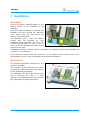
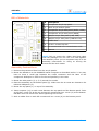
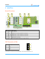
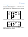
AbioWire
1-Wire Card for BCM2835-based computer
User Manual
July 2013
AbioWire
Table of Contents
1
Features
4
2
Technical Specifications
4
3
Installation
AbioWire
Enclosure
Bill of Materials
Assembly Instructions
5
5
5
6
6
4
AbioWire
Board Overview
I2C Connector (K18)
1-Wire Connector (K1-K17)
7
7
7
8
5
I2C Bus
Slave Addresses
Real-time Clock
1-Wire Controllers
8
8
8
8
6
Software
Overview
Accessing I2C from Software
Direct I/O
i2c-dev Interface
Revision of your BCM2835-based Computer
Real-time Clock
Package ows
Installation
Specifying the Hardware
Enumerating 1-Wire Slaves
Reading 1-Wire Sensors
Package owfs
9
9
9
9
10
10
10
11
11
11
11
12
12
7
ESD/Lightning Protection
13
8
Disclaimer
14
9
Contact Information
14
2
User Manual
AbioWire
Revision History
Date
Authors
Description
2013-04-13 Peter S'heeren
First release.
2013-07-09 Peter S'heeren
Second release.
User Manual
3
AbioWire
1 Features
▪
Three 1-Wire controllers providing a
total of seventeen 1-Wire channels.
▪
Connector for I2C bus operating at 5 V.
▪
Battery backed up real-time clock and
calendar with integrated temperature
compensated crystal oscillator and a
32.768 kHz quartz crystal.
▪
Compact footprint due to the use of
SMD components.
▪
Free software.
▪
Works with the Axiris ows software
package.
▪
Works with the owfs software package.
Applications include:
▪
Weather station.
▪
Home automation.
2 Technical Specifications
Dimensions
73 mm x 60 mm x 22 mm (W x D x H)
Weight
27 g (without battery)
RTC backup power
10 years
4
User Manual
AbioWire
3 Installation
AbioWire
First of all, place a CR2032 battery in the
battery holder on the backside of the
AbioWire.
Note that when no battery is present, the
AbioWire will work except the real-time
clock won't keep the time when the
system is powered down.
The AbioWire has a 2x13 pin female
header that fits perfectly on your
BCM2835-based computer. Be sure you
connect the AbioWire in such a way it
hovers over the computer as shown in the
picture to the right.
A dedicated enclosure for the combo is available. The enclosure ensures the AbioWire fits
correctly on the computer.
If you decide to provide your own enclosure, or no enclosure at all, then be sure to fix
the AbioWire in such a way its backside can't touch the computer.
Enclosure
An enclosure specifically designed for the
combo is available.
The enclosure comes with holes on top for
connecting 1-Wire devices and I2C devices
to the dedicated pin headers.
The AbioWire has three protrusions that
aid in mounting the card in a fixed
position. The dedicated enclosure provides
the right holes for these protrusions.
User Manual
5
AbioWire
Bill of Materials
3
1
4
6
5
Description
1
Transparent acrylic top panel
2
Black acrylic bottom panel
3
Transparent acrylic side panel (audio, video)
4
Transparent acrylic side panel (HDMI)
5
Opaque acrylic side panel (LAN, USB)
6
Opaque acrylic side panel (USB Micro-B)
7
Rubber feet
8
M3 hex. screws top side
9
M3 countersunk hex. screws bottom side
10
2
7
#
8
9 10
Spacers
HINT! Did you notice the rubber band that came
with the package? You can use it to hold together
the assembly when you've completed step 5 of the
assembly instructions. In doing so driving the
screws will be much easier.
Assembly Instructions
1. Remove the protective films from the acrylic panels.
2. Mount the AbioWire on the BCM2835-based computer as described earlier. 2. You may
have to leave a small gap between the card's connector and the base of the
computer's GPIO pins in order to fit the card perfectly in the case.
3. Mount the side panels (3, 4, 5, 6) around the combo.
4. Place the assembly on the bottom panel (2). Make sure the air vents are closest to the
LAN and USB panel (5).
5. Mount the top panel (1) on top of the assembly.
6. Insert a spacer (10) in each corner between the top panel and the bottom panel. Drive
an M3 hex. screw (8) at the top and an M3 countersunk hex. screw (9) at the bottom.
DO NOT exert too much force when tightening the screws!
7. Stick a rubber foot on each M3 countersunk hex. screw (9) on the bottom panel.
6
User Manual
AbioWire
4 AbioWire
Board Overview
1
3
4
5
6
2
Mark
Label
1
K18
I2C connector
2
K17
DS2482-100 1-Wire controller C connector
3
K1-K8
DS2482-800 1-Wire controller A connectors
4
Description
K9-K16 DS2482-800 1-Wire controller B connectors
5
K19
6
B1
GPIO female connector
RTC backup power battery, 3 V type CR2032
I2C Connector (K18)
Mark
Description
1
5V
2
GND
3
SDA
4
SCL
1
2
3
4
Connection to the I2C bus on the AbioWire. This I2C bus operates at 5 V.
User Manual
7
AbioWire
1-Wire Connector (K1-K17)
Mark
Description
1
5V
2
DQ
3
GND
1
2
3
This connector is typically used to connect a 1-Wire channel to a 1-Wire slave with a
similar connector, or a breakout board.
5 I2C Bus
Slave Addresses
The I2C bus on the AbioWire interconnects your BCM2835-based computer with a set of
I2C slave devices. The slave addresses are:
Address
Slave Device
1010001b PCF2129A real-time clock
0011000b 1-Wire controller A, DS2482-800, 8 channels
0011001b 1-Wire controller B, DS2482-800, 8 channels
0011010b 1-Wire controller C, DS2482-100, 1 channel
Real-time Clock
The PCF2129A is a real-time clock and calendar with an integrated temperature
compensated crystal oscillator and a 32.768 kHz quartz crystal. The PCF2129A has a
backup battery switch-over circuit, a programmable watchdog function, a timestamp
function, and many other features.
The board has a holder for a CR2032 battery that functions as backup power for the
PCF2129A.
1-Wire Controllers
The three 1-Wire controllers allow software to communicate with three 1-Wire slaves
concurrently.
The 1-Wire controllers provide a total of seventeen 1-Wire buses.
8
User Manual
AbioWire
6 Software
Overview
The AbioWire is supported by a number of software packages that run on your BCM2835based computer with Linux for ARM installed.
This document makes the following assumptions:
▪
You've installed Debian6 Linux or a derivative distribution on the SD card of your
BCM2835-based computer.
▪
You've a personal log in that's not root.
▪
You know how to run programs as root (sudo command, setuid access right flag).
▪
You know how to log in as root (log in prompt, the su command).
This document describes commands entered at the command prompt. When entering a
command at the prompt of your personal log in, the document uses the $ notation. For
example:
$ sudo ./owsenum
A command entered at the prompt of the root log in is written with the # notation. For
example:
# ./owsenum
Accessing I2C from Software
Software has two ways of accessing the I2C hardware on your BCM2835-based
computer:
▪
Direct I/O.
▪
Using the Linux i2c-dev interface.
Direct I/O
Direct I/O means the programs that run on your BCM2835-based computer directly
communicate with the AbioWire from user-mode using the first serial controller (BSC0) or
the second serial controller (BSC1) on the BCM2835 application processor.
Obviously using direct I/O is appropriate when no I2C driver is loaded, or at least the
BSC that connects to the AbioWire is not under control of any I2C driver.
Direct I/O requires root privileges.
IMPORTANT!
Do not force the programs to use direct I/O if I2C drivers are present. Doing so may
disrupt the proper working of the I2C drivers and subsequently hang or crash the
operating system.
User Manual
9
AbioWire
i2c-dev Interface
I2C driver support in Linux includes a driver named i2c-dev. This driver offers a file
interface to the I2C adapters from user-mode through files in the /dev directory. These
files are named /dev/i2c-<n> where <n> is a number starting from zero.
If the i2c-dev interface is not present, you can activate it by running the following
commands as root:
# modprobe i2c-bcm2708
# modprobe i2c-dev
The following files will be created:
▪
/dev/i2c-0 – i2c-dev interface for BSC0.
▪
/dev/i2c-1 – i2c-dev interface for BSC1.
Normally access to these files requires root privileges.
Revision of your BCM2835-based Computer
There are currently two main revisions of the computer. The GPIO pins are not
compatible between these revisions. Although the incompatibility doesn't affect the
AbioWire hardware, it does affect the software as follows:
▪
Revision 1: The GPIO header pins 3 and 5 are wired to BSC0 of the BCM2835.
▪
Revision 2: The GPIO header pins 3 and 5 are wired to BSC1 of the BCM2835.
A number of programs are able to auto-detect the revision of the computer and as such
the BSC to use.
If you're using the ows package, run the following program as root:
# ./owsenum -bscdetect -v
There are three possible outcomes:
(a) The program has detected direct I/O:
Detecting BSC
Adding i2cbus 0 bsc 1
(b) The program has detected the i2c-dev driver is present:
Detecting BSC
Adding i2cbus 0 i2c-dev /dev/i2c-1
(c) The program has determined it's not running on a BCM2835-based computer:
Detecting BSC
BCM2835 not detected, skipping devices for bscdetect
Real-time Clock
You can install the abiortc package to take advantage of the real-time clock. It's
available from the Axiris website.
10
User Manual
AbioWire
Package ows
This software package for 1-Wire is provided by Axiris. It's available from the Axiris
website.
The ows programs support several 1-Wire adapters and run on a variety of systems. This
document provides a quick guide for most common tasks for your AbioWire. Refer to the
ows documentation for more information.
Installation
Unpack the ows package in a local directory in your home directory on your BCM2835based computer.
Run the install.sh script in the context of your user account to install the ows group of
programs in Linux.
Be sure to run the installation script from the command line rather than the file manager.
The script will sudo and as such the system may ask for the root password.
The ows package is installed in directory /opt/ows. You'll have to cd to this directory to
run the programs.
Specifying the Hardware
To see the outcome of the BSC detection procedure, run the following command as root:
# ./owsenum -bscdetect -v
The ows programs accept a standard set of options for specifying 1-Wire adapters.
Options
Description
-bscdetect abiowire
Auto-detect BSC and interfacing type.
-bsc 0 abiowire
Use direct I/O with AbioWire on BSC 0.
-bsc 1 abiowire
Use direct I/O with AbioWire on BSC 1.
-i2cdev /dev/i2c-0 abiowire
Use i2c-dev with AbioWire on BSC 0.
-i2cdev /dev/i2c-1 abiowire
Use i2c-dev with AbioWire on BSC 1.
It's also possible to work with individual 1-Wire controllers of the AbioWire:
Options
Description
-bscdetect ds2482 24
Auto-detect BSC and interfacing type, use the first 1Wire controller (I2C address is 24).
-bsc 0 ds2482 25
Use direct I/O with the second 1-Wire controller on
BSC 0.
-i2cdev /dev/i2c-1 ds2482 26 Use i2c-dev with the third 1-Wire controller on BSC 1.
You don't need to specify the type of 1-Wire controller, the ows software will distinguish
between a DS2482-800 chip and a DS2482-100 chip.
Enumerating 1-Wire Slaves
To enumerate all 1-Wire slaves connected to the AbioWire:
User Manual
11
AbioWire
# ./owsenum -bscdetect abiowire
Reading 1-Wire Sensors
To read out your 1-Wire sensor devices, you first create a topology file that describes
your 1-Wire networks. Once the file has been created, you feed it to program owsrds
that will read out the actual sensor data. Run as root:
# ./owsenum -bscdetect abiowire -hub -topo mynetworks.txt
# ./owsrds -bscdetect abiowire -topo mynetworks.txt
The topology file needs to be created only once. You can simply run owsrds periodically
(using cron for example) to read out the sensor data. You should recreate a topology file
only when you change the topology of the 1-Wire sensor devices on your 1-Wire
networks.
If you reconnect your 1-Wire networks to different channel connectors on the AbioWire,
don't worry. The owsrds program will detect your networks and access the correct
channel for each network.
Package owfs
The AbioWire can be used with owfs, the 1-Wire File System. This software package is
available from the following website:
http://www.owfs.org/
The owfs software includes programs that expose the 1-Wire hardware in a variety of
ways to the system:
▪
owfs: Creates a file system in a specified mount directory. This program requires
software package libfuse.
▪
owhttpd: Sets up a web server.
▪
owftpd: Sets up an FTP server.
▪
owserver: A server that allows multiple client programs to access the 1-Wire
hardware.
These programs support a uniform command line syntax for specifying which 1-Wire
adapters to detect and to expose. For the AbioWire, the --i2c command line option is of
importance.
Suppose you want to set up a web server that listens to port 80. Suppose the AbioWire is
connected to BSC1 of the computer. Enter the following command as root in the bin
directory of owfs:
# ./owhttpd -p 80 –-i2c=/dev/i2c-1:0 –-i2c=/dev/i2c-1:1 –-i2c=/dev/i2c-1:2
The /dev/i2c-<n>:<i> syntax denotes offset <n> from I2C address 0011000b on I2C
bus of <i>. The mentioned command line syntax thus tells owhttpd to look for 1-Wire
controllers at addresses 0011000b, 0011001b and 0011010b on the I2C bus of BSC1.
The type of 1-Wire controller doesn't need to be specified; the owfs software will
distinguish between a DS2482-800 chip and a DS2482-100 chip.
Refer to the owfs documentation for more information.
12
User Manual
AbioWire
7 ESD/Lightning Protection
When you're planning to expose your 1-Wire network to the open air or an hostile
environment, ESD and nearby lightning strikes may hit your 1-Wire network and destroy
the AbioWire and 1-Wire slaves in the process.
We strongly advice to protect your AbioWire if such problems are real. Here's an example
circuit to protect a 1-Wire adapter. Note that for the correct functioning of the circuit, a
reliable earth connection is required (computer chassis, mains earth connector, grounding
pin, …).
22R
1-Wire
Network
1N5404
DQ
1N5404
DQ
22R
1.5KE10ACCT
10V 1500W
GND
1N5404
GND
1-Wire
Adapter
PE
You can opt to protect 1-Wire slaves as well. Here's an example circuit to protect a 1Wire slave from certain destructive discharges on the 1-Wire network:
47R
1-Wire
Network
GND
DQ
1N4004
DQ
1N4004
12V 1W
1-Wire
Slave
GND
The diagrams presented here are example circuits. It's the end-user's responsibility to
provide the required protection measures to prevent the AbioWire from being destroyed
by electrical discharges and similar phenomenons.
User Manual
13
AbioWire
8 Disclaimer
Axiris products are not designed, authorized or warranted to be suitable for use in space,
nautical, space, military, medical, life-critical or safety-critical devices or equipment.
Axiris products are not designed, authorized or warranted to be suitable for use in
applications where failure or malfunction of an Axiris product can result in personal
injury, death, property damage or environmental damage.
Axiris accepts no liability for inclusion or use of Axiris products in such applications and
such inclusion or use is at the customer's own risk. Should the customer use Axiris
products for such application, the customer shall indemnify and hold Axiris harmless
against all claims and damages.
9 Contact Information
Official website: http://www.axiris.be/
14
User Manual