1
Measuring Microscopes
Optical Measuring
MF/MF-U Series
Catalog No. E14003(3)
2
Expectations for Measuring Microscopes
A measuring microscope can be used to perform both measurement and observation, inspecting a variety of objects including semiconductors, electronic and electrical
components, automobile precision components, resin moldings, tools, and medical products. For example, this type of microscope can be used to measure an object
that is too soft for contact measurement or the diameter of a hole that is too small for a measurement probe to contact.
A balance between optical performance, overall accuracy, and ease of use is an important requirement for a measuring microscope. A measuring microscope enables you to
observe elements that have either been invisible or difficult to see and measure them. Mitutoyo believes that expectations for measuring microscopes will continue to grow
and that user friendliness, high measurement data throughput, and environmental friendliness will be demanded at the same time. To play our part in supporting essential
technologies in the industry, we will continue to provide high-quality, high-definition measuring microscopes, while staying true to our commitments and beliefs.
From Design and Development to Support after Delivery
Mitutoyo designs, develops and manufactures all microscope parts – including those for the body, such as the lenses and optical tube – and the highly accurate
built-in digital scale. Our in-house design and development processes allow us to, proactively, offer consultation on special requirements and respond to customer
requests, such as those for customized fabrication.
Mitutoyo carefully delivers the microscope from the production plant to its desired destination*, and then installs and adjusts it there. The packaging box is recyclable,
which enables the customer to eliminate as much waste as possible at the delivery destination. After adjustment, customers can sign a maintenance contract or use
our reliable after-sales services according to their needs, which ensures that they can confidently use their Mitutoyo microscope for a long time to come.
*If a dedicated delivery service is used.
3
Lineup
Motor-Driven X/Y/Z-axes Models
Motor-Driven Z-axis Models
Standard models
High accuracy measurement, improved operability and a choice of models to suit practically any application. Lineup
now includes motor-driven Z-axis models.
4
Mitutoyo's quick release mechanism on the X and Y axes allows fast stage movement and easy positioning
while keeping both hands on the control handles.
Measuring Microscope
Measuring Microscope
MF Series
MF-U Series
Stage operation for the X and Y axes is unchanged but the motorized Z-axis provides comfortable operation and enables
dynamic up/down operation with a jog shuttle as well as accurate fine-focusing control.
Motor-Driven Z-axis
Measuring Microscope
Motor-Driven Z-axis
Measuring Microscope
MF-U Series
MF Series
Motorized X, Y, and Z axes allows easy stage movement and focus adjustment and eliminates operator fatigue.
Motor-Driven
Measuring Microscope
MF Series
Motor-Driven
Measuring Microscope
MF-U Series
Motor-Driven
Measuring Microscope
MF-U Series (LAF model)
CONTENTS
Measuring Microscopes
Options
Features— ———————————————————P8 - 11
Specifications— ——————————————— P12 - 13
Dimensions— —————————————————— P16
System Diagrams— ——————————————— P18
Illumination— ———————————————————————— P38 - 39
MF series
Objectives— ————————————————————————— P36 - 37
Manual Image Measurement Vision Unit— ——————————— P40
2-D Data Processing Unit QM-Data200— ———————————— P41
Focus pilot, Sliding Nosepieces and Turrets— ——————————— P43
Rotary table with fine feed wheel, V-block with clamp,— ———— P44
Swivel center support, Holder with clamp and Stage adapter
Universal Measuring Microscopes
MF-U series
Features— ———————————————————P8 - 11
Specifications— ——————————————— P14 - 15
Dimensions— —————————————————— P17
System Diagrams— ——————————————— P19
Polarization unit, Differential interference contrast unit, Illumination —— P45
filter, C-mount adapter, 0.5X TV adapter and Stage micrometer
Mounting stand, Vibration damping stand and Lens cleaning set— — P46
Reticle— ————————————————————————————— P47
Motor-Driven Z-axis Measuring Microscopes
MF series/MF-U series
Features— —————————————————— P20 - 22
Specifications— ——————————————— P23 - 24
Dimensions— —————————————————— P25
System Diagrams— ————————————— P34 - 35
Motor-Driven Measuring Microscopes
MF series/MF-U series
Features— —————————————————— P26 - 29
Specifications— ——————————————— P30 - 31
Dimensions— ———————————————— P32 - 33
System Diagrams— ————————————— P34 - 35
5
In Pursuit of Optical Performance — The Essence of Microscopy —
These microscopes use an optical design for the optical tube and objective to reduce flare within
the optical system as much possible and so enable the clear display of subtle details of inspected
objects. With this series, even the surface of black resin can also be clearly observed in high
contrast. The MF-U Series is equipped with the proven FS optical system metal microscope head
and displays clear images with high color reproducibility in which the three prime colors are
corrected. (The plan apochromat specifications are used for the objective*.)
For the MF and MF-U Series, an LED- or halogen-based lighting system can be used. Higher
lighting efficiency and sufficient illuminance within the optical system provide an environment
for high-magnification measurement and bright-field and dark-field observation in which you can
work efficiently without getting tired.
* Specifications according to which aberrations across the image surface and chromatic aberrations in the wave length
range of the three primary colors (blue, yellow and red ) are corrected.
In Pursuit of Measuring Accuracy — Close to JIS Grade 0 —
(Common to MF D and MF-U D)
Example
X and Y axes: (2.2+0.02L)µm or less
Measuring
Error
Reference) Measuring accuracy of each axis of a JIS B 7153
measuring microscope (at 20°C)
Grade 0: (2+0.01L)µm or less
Grade 1: (4+0.02L)µm or less L: measuring length (mm)
0
Grade 1 error limits
Typical X-axis performance
Measuring range
A measuring microscope must have high level optical performance and overall measuring accuracy. The MF
and MF-U Series realizes the measuring accuracy stipulated by the above standards for every stage size*.
This series is useful for any measurement because it offers both long stroke measurement and high accuracy
at the same time.
*Conforms to the JIS B 7153 measurement method for the X and Y axes. The above measuring accuracy graph is an example and does
not represent all main unit accuracies.
The digital scale built into the microscope is a photoelectric type transmission linear encoder with a maximum
response speed of 50m/min. This highly accurate encoder was developed in an underground laboratory
where the world’s best scale accuracy evaluation technique is available.
Mitutoyo was the first manufacturer to acquire ISO/IEC 17025(JCSS) accreditation for calibrating line
standards (standard scales up to 500mm long) in Japan.
For Safe Use — Traceability to National Standards —
To establish and maintain the traceability of measuring tools
and instruments, Mitutoyo uses length standards traceable
to the national standards in Japan to calibrate the standard
used to calibrate measuring tools and instruments.
National standard
Secondary standard
Working standard
Working standard
National Metrology Institute of Japan, National Institute of
Advanced Industrial Science and Technology
(NMIJ/AIST)
The atomic clock synchronized to UTC and the optical frequency comb
Mitutoyo Utsunomiya Measurement Standards Calibration Center
(JCSS accredited calibration laboratory No. 0031)
Iodine stabilized He-Ne laser for length purposes with 633nm wavelength
Mitutoyo Utsunomiya Measurement Standards Calibration Center
Stabilized He-Ne laser for length purposes with 633nm wavelength, for actual use
Optical interferometer
Standard and reference scales
Measuring microscopes
6
Solutions Provided by Measuring Microscopes
Observation and Inspection of Small Areas
By using various modes of illumination, the MF Series can more precisely
reproduce the colors and shapes of objects that are observed and inspected.
The MF-U Series microscopes are high value-added instruments that offer
microscope observation functions such as dark-field mode (to observe surface
scratches and small steps, which are difficult to see in bright-field mode), simple
polarization (to observe coloration or contrast through the polarizer or analyzer
using polarization properties), and differential interference (to observe small
surface steps and other elements in color contrast using a polarizing filter with
a differential interference prism), as well as measurement functions.
Bright-field observation
Dark-field observation
Polarized observation
Differential interference observation
Easy Image Photography
Anyone can easily photograph microscope images by attaching a digital camera
to the microscope. Because a general-purpose C-mount adapter is used, any
digital camera model that supports C-mounting can be attached. For example,
several people can simultaneously analyze and evaluate the microscope image
displayed on the monitor, or generation of an inspection chart attached to the
image can be automated.
Microscope-Based High-Resolution Measurement
It is possible to build a manual image measurement system by equipping a
measuring microscope with the image measurement option (the Vision Unit).
Because the software constantly transmits stage displacements, measurements
within the camera imaging range (on the screen) as well as those wider than
the screen are supported. In addition, automatic edge detection provides an
efficient measurement environment with a high throughput.
However, eyepiece resolution might be superior to camera resolution in
some cases. For example, the surface of a molded item made of black resin
might be clearer to the naked eye than to the camera (monitor observation).
Therefore, a measuring microscope that also enables you to see the surface
and other elements is said to be a system that has a very high added value. It
is recommended to connect the two-dimensional data processing unit QMData 200 (a dedicated control unit) to the measuring microscope for such
dimensional measurement.
MF-B2017D + Vision Unit
MF-UB1010D + QM-Data200
7
Measuring Microscopes MF Series
Universal Measuring Microscopes MF-U
Series
New optional sliding nosepiece allows one of two objectives to be quickly moved into position
to change the magnification, and a circular illuminator to be fitted. Operability has improved
in this series by allowing freedom of mounting position for the digital display.
Sliding Nosepiece
(Factory-set option of MF D)
New
design
Sliding nosepiece with two objectives mounted.
The MF (finite correction optical system) measuring microscope usually only
allows a single objective to be mounted which needs to be replaced for every
magnification change. The new sliding nosepiece allows two objectives to be
mounted, thus allowing quick magnification change. This nosepiece design
also enables installation of an LED circular illumination unit. Thanks to these
arrangements, a quick change of magnification and versatile illumination is
supported.
8
Dedicated LED circular illuminator mounted on the sliding nosepiece.
High Visibility Digital Display
(Common to MF D and MF-U D)
Front of display
New
design
Rear of display
Because the resolution can be switched to 1μm, 0.5μm, or 0.1μm for the
digital display (two or three axes), which is a standard accessory for all
models, high-discrimination measurement can be performed. The zeroset,
direction changeover, and smoothing functions are also standard.
(Zero can be set using the switch near the X or Y handwheels.)
The display is low-profile but has large digits and can be mounted in the
position most convenient for the operator.
The digital display can be installed on the left or right side of the column.
Because the general-purpose RS-232C format is adopted for data transfer,
data can be output to a standard printer or personal computer. It is also
possible to output the display readings to spreadsheet software.
9
Measuring Microscopes MF Series
Universal Measuring Microscopes MF-U
Height Measurement with a High Focus Repeatability
Wide-Field Observation
(Option on MF D / factory-set option on MF-U D) For details, see page 42.
Focus repeatability is important when measuring a vertical step or other element
using the microscope.
In particular, measurement errors due to the depth of focus of the objective are
inevitable. The MF and MF-U Series measuring microscopes have a focus pilot,
which enhances focus repeatability. The focus pilot is mounted on the TV camera
port section in the main unit as an add-on unit and enables focusing position
detection with high accuracy and repeatability. This realizes higher repeatability
than a visual check and decreases variation in measured values caused by human
error.
Two types of focus patterns are available, either of which can be selected
according to the size of the part to be focused on or the surface state, material,
or other properties of the inspected object. A clear, bright, high-intensity LED
(green or red) is employed as the light source. The focus pattern, for which
brightness can be steplessly adjusted, can be checked on the eyepiece or TV
monitor. This substantially improves measurement throughput.
(Common to MF D and MF-U D)
Series
The best-in-class eyepiece field number* of 24mm (for WF10X)
offers a wide viewing field that helps prevent extended observation
or measurement from affecting your eyes or causing fatigue. The
WF10X eyepiece has wider diopter adjustment ranges on the left
and right sides than older products.
24mm
MF
* Width of an inspected object that can be seen across the whole viewing field when a 1X objective
is used
(1)
LED and Halogen Light Options for Transmitted and
Reflected Illumination
(Options common and essential to MF D/MF-U D)
(1)
(2)
(2)
Transmitted LED illumination unit
(Common to MF/MF-U Series)
Reflected LED illumination unit
(for MF Series)
Reflected LED illumination unit
(for MF-U Series)
An LED or halogen light can be selected for the coaxial illumination in the main
unit. While the conventional halogen light can be used for observation and
measurement, the LED light can also be selected if you want to reduce the time
lost to replace a failed halogen bulb with a new one and need high intensity
illumination that quickly responds to brightness adjustment.
The LED light has a long working life*1 and will not suddenly fail.
In addition, the visibility, brightness and coloration are constant because, unlike
fluorescent tubes, the LED light is free from glare and changes in color temperature.
This means less eye fatigue after extended observation. Because the LED consumes
little power and emits little heat radiation, measurement is economical and produces
less heat-induced effects on inspected objects*2. In addition, this light source is impact
resistant and does not contain environmental toxins.
All the models in the MF and MF-U Series have transmitted and reflected
illumination aperture-diaphragms as standard to enable observation and
measurement with less light diffraction.
*1: The working life will be shorter if the maximum illuminance is always used.
*2: The LED light for MF/MF-U D Series incorporates a quiet cooling fan to further reduce heat effects.
LED illumination
10
Halogen illumination
220mm
Quick Release Mechanism*1 and Zero-set Switch
Incorporated*2 (Common to MF D and MF-U D)
Stage Variations Including Long Stroke
300mm
(Common to MF D and MF-U D)
m
220m
Z axis
220mm
30
220mm
m
0m
Quick release handle
Y axis
Zero set
button
200mm
300mm
X axis 400mm
MF-B4020D
The stage movement can be switched between extremely coarse and fine (FREE
and LOCK) by using the quick release handles on the X and Y handles.
These handles are useful for freeing the stage when the distance to the
measurement position is long or you want to quickly return to a reference
position.
Because this mechanism uses the twist roller method, switching causes little
impact and enables smooth movement. Because the display zero-set switches are
located near the handles*2, you can focus on the eyepiece during measurement
and keep your hand near the handle almost all the time except when adjusting
the focus.
Inspected objects vary in size.
Widely used in every industry, this series provides many measurement stroke
variations.
This series offers a stage for long stroke measurement of 400×200×220mm in X,
Y and Z. This is useful when measuring printed circuit boards, shafts, knife tools
and other objects. Although the standard model has a Z-axis range of 220mm,
the Z axis can be extended with a column upgrade.
A swivel rotation mechanism* is also provided as standard. This mechanism
is useful when fixing an inspected object in parallel with the table movement
direction.
*1: Patent registered in Japan
*2: The zero-set buttons are located on the X and Y axes, not the Z axis.
*Only for models with a Y-axis range of 170mm or longer
Z-Axis Handles Provided on Both Sides
of Standard Model (MF D and MF-U D)
Tilting Optical Tube of
Standard Model (MF-U D)
Highly Rigid Column Base
(Common to MF D and MF-U D)
MF D
MF-U D
Because the Z axis handles are placed on both
sides of the column in standard models, the
user can easily use one of them regardless of
handedness.
The digital display can also be installed on either
side of the column to set up an environment
suited to the user’s dominant hand.
Ergonomics have also been taken into
consideration, and the handle is located in a
position where a user of shorter stature can
comfortably turn it.
Comfortable observation is possible because the eye point can be adjusted to a
position suitable for the user’s stature.
The angle of the column can be fixed anywhere between 0° and 30°.
The reticle in the optical tube can be
replaced.
The base that supports the column
holding the optical tube and the rest of
the microscope must be absolutely rigid
to enable observation and measurement
using any amount of magnification.
This series has been repeatedly evaluated
Column
from various aspects including a drop
test*, transportation test*, and smoothing test and provides
steady vision and consistent accuracy over the entire stroke.
To enhance rigidity, horizontal ribs have been added within the
column. The power supply section is located outside the base to
reduce heat effects for higher base rigidity and highly accurate
measurement.
*Proprietary Mitutoyo tests executed using appropriate procedures.
11
Measuring Microscopes
MF Series
MF-B1010D
* The binocular tube (eyepiece) and illumination
unit are optional accessories.
MF-B2010D
* The binocular tube (eyepiece) and illumination
unit are optional accessories.
Features
■ Observation with a clear and flare-less erect image and a wide field of view
■ Measuring accuracy that is the highest in its class (and conforms to JIS B 7153)
■ ML series, high-NA objectives that are specially designed for the MF series (long working distance type)
■ Illumination unit (reflected/transmitted) selectable from a high-intensity LED or halogen bulb (required)
■ Variable aperture diaphragm (reflected/transmitted) allows adjustment for contrast and resolution
■ Variety of standardized stages in sizes up to 400×200mm
■ Quick-release mechanism useful for moving the stage quickly when measuring workpieces that are large in size or quantity
■ Coarse/fine feed handles equipped as standard on both sides allow precise focus and observation measurement regardless of
handedness
■ High-magnification eyepiece observation up to 2000X
■ Standard measuring microscope that has a wide variety of optional accessories including a Vision Unit and various digital CCD cameras
■ Low-noise design
12
MF-B2017D
MF-B3017D
* The binocular tube (eyepiece) and
illumination unit are optional accessories.
MF-B4020D
* The binocular tube (eyepiece) and
illumination unit are optional accessories.
* The binocular tube (eyepiece) and
illumination unit are optional accessories.
Specifications
Without
Z-axis scale
With
Z-axis scale
Model No.
Order No.
Model No.
Order No.
MF-A1010D
176-861*
MF-B1010D
176-866*
Optical tube (eyepiece(s) required)
Observation image
Observation method
Eyepiece (optional) Adjustable diopter
Objective (optional)
Max. workpiece height
Z axis
Feed mechanism
Illumination unit
Illumination filter
Measurement range
Tabletop size
Effective stage glass size
Swiveling angle
Stage
Maximum table loading
Quick-release mechanism
Zero-set button
Measurement system
Measuring accuracy*1
(X and Y axes, when not loaded)
Minimum reading
Digital display Display axes
Functions
Main unit dimensions (WxDxH)
Main unit mass
Control unit dimensions and mass
Maximum power consumption
(with the illumination unit)
MF-A2010D
176-862*
MF-B2010D
176-867*
MF-A2017D
176-863*
MF-B2017D
176-868*
MF-A3017D
176-864*
MF-B3017D
176-869*
MF-A4020D
176-865*
MF-B4020D
176-870*
Monocular or binocular (angle of column: 25°)
Standard TV camera port for all models, reticle (broken cross-hair, line width: 5μm), optical path switching
(observation/TV camera = 50/50)
Erect image
Bright-field observation
10X (eyepiece field number: 24), 15X, 20X
Note: Monocular - one 10X eyepiece provided as standard; Binocular - two 10X eyepieces provided as standard
ML objective 3X (provided as standard), 1X, 5X, 10X, 20X, 50X, 100X
150mm
220mm
Coaxial coarse and fine feed, handles on both sides (coarse: 30mm/rotation, fine: 0.2mm/rotation)
LED or halogen is required.
One GIF filter is provided as standard (and mountable for both transmitted and reflected illumination)
100×100mm
200×100mm
200×170mm
300×170mm
400×200mm
280×280mm
350×280mm
410×342mm
510×342mm
610×342mm
180×180mm
250×150mm
270×240mm
370×240mm
440×240mm
—
±5° (left)
±3° (left)
10kg
20kg
15kg
Provided as standard for the X and Y axes
Provided as standard for the X and Y axes (and for the Z axis only for the MF-B type)
High-accuracy digital scale
(2.2+0.02L)μm, L: measuring length(mm)
562×730×667mm
67kg
1/0.5/0.1μm switchable
X and Y (or X, Y, and Z only for the MF-B type)
Zero-setting, direction switching, RS232C output, USB output (specific to QSPAK)
624×745×667mm
632×892×782mm
682×892×782mm
71kg
148kg
156kg
114(W×360(D×96(H)mm LED: 3.5kg/Halogen: 4kg
LED: 45W
757×907×782mm
162kg
Halogen bulb: 160W
* The following suffixes are added to the order No. (e.g.: 176-861-10) to specify the User Manual's language: -10 for English; -11 for Chinese; No suffix for Japanese.
*1 Measured in conformance with JIS B 7153
Replacement halogen bulb
(reflected/transmitted)
Standard: 513667 (12V/50W)
Long life: 12BAB345 (12V/50W)
13
Universal Measuring Microscopes
MF-U Series
MF-UB1010D
* The turret, objectives and illumination unit are
optional accessories.
MF-UB2010D
* The turret, objectives and illumination unit are
optional accessories.
Features
■ Observation with a clear and flare-less erect image and a wide field of view
■ Measuring accuracy that is the highest in its class (and conforms to JIS B 7153)
■ Proven M Plan Apo/BD Plan Apo/G Plan Apo series, high-NA objectives from the FS optical system (long working distance type)
■ Integration of metallurgical and measurement microscope functions provides a high-resolution observation and high-accuracy measurement
solution
■ Illumination unit (reflected/transmitted) selectable from a high-intensity LED or halogen bulb (required)
* Only the halogen light source for transmitted illumination is provided as standard accessory. A seperate light source for transmitted illumination must be ordered additionally as optional accessory.
■ Variable aperture diaphragm (reflected/transmitted) allows adjustment for contrast and resolution
■ Variety of standardized stages in sizes up to 400×200mm
■ Quick-release mechanism useful for moving the stage quickly when measuring workpieces that are large in size or quantity
■ Coarse/fine feed handles equipped as standard on both sides allow precise focus and observation measurement regardless of handedness
■ High-magnification eyepiece observation up to 4000X (when using M Plan Apo SL200X)
■ Standard measuring microscope that has a wide variety of optional accessories including a Vision Unit and various digital CCD cameras
■ Low-noise design
14
MF-UB2017D
* The turret, objectives and illumination unit are optional
accessories.
MF-UB3017D
MF-UB4020D
* The turret, objectives and illumination unit are optional
accessories.
* The turret, objectives and illumination unit are optional
accessories.
Specifications
Without
Z-axis scale
With
Z-axis scale
Without
BD
Z-axis scale
(bright-field/
dark-field) With
Z-axis scale
BF
(brightfield)
Model No.
Order No.
Model No.
Order No.
Model No.
Order No.
Model No.
Order No.
Optical tube
Observation image
Observation method
Eyepiece (optional) Adjustable diopter
Bright-field (BF)
Turret
(required)
Bright-field/dark-field (BD)
Bright-field (BF)
Objective
(optional)
Bright-field/dark-field (BD)
Max. workpiece height
Z axis
Feed mechanism
Illumination unit
Illumination filter
Measuring range
Tabletop size
Effective stage glass size
Swiveling angle
Stage
Maximum table loading
Quick-release mechanism
Zero-set button
Measurement system
Measuring accuracy*1
(X and Y axes, when not loaded)
Minimum reading
Digital display Display axes
Functions
Main unit dimensions (WxDxH)
Main unit mass
Control unit dimensions and mass
Maximum power consumption
(with the illumination unit)
MF-UA1010D
176-871*
MF-UB1010D
176-876*
MF-UC1010D
176-881*
MF-UD1010D
176-886*
MF-UA2010D
176-872*
MF-UB2010D
176-877*
MF-UC2010D
176-882*
MF-UD2010D
176-887*
MF-UA2017D
176-873*
MF-UB2017D
176-878*
MF-UC2017D
176-883*
MF-UD2017D
176-888*
MF-UA3017D
176-874*
MF-UB3017D
176-879*
MF-UC3017D
176-884*
MF-UD3017D
176-889*
MF-UA4020D
176-875*
MF-UB4020D
176-880*
MF-UC4020D
176-885*
MF-UD4020D
176-890*
Tilting trinocular tube (angle of column: 0 to 30°), Siedentoph type (pupil distance adjustment: 51 to 76mm), built-in 1X tube lens, reticle (broken crosshair, line width: 5μm), optical path switching (observation/TV camera = 50/50)
Erect image
BF, DF (only for MF-UC and UD types), simple polarization, differential interference
10X (eyepiece field number: 24, two eyepieces provided as standard), 15X, 20X
Adjustable manual turret or adjustable power turret (Select one.)
Adjustable manual turret or adjustable power turret (Select one.)
All lenses including the M Plan Apo, M Plan Apo SL, and G Plan Apo series
All lenses including the BD Plan Apo and BD plan Apo L series
150mm
220mm
Coaxial coarse and fine feed, handles on both sides (coarse: 10mm/rotation, fine: 0.1mm/rotation)
LED or halogen is required.
One GIF filter is provided as standard (and mountable for both transmitted and reflected illumination)
100×100mm
200×100mm
200×170mm
300×170mm
400×200mm
280×280mm
350×280mm
410×342mm
510×342mm
610×342mm
180×180mm
250×150mm
270×240mm
370×240mm
440×240mm
—
±5° (left)
±3° (left)
10kg
20kg
15kg
Provided as standard for the X and Y axes
Provided as standard for the X and Y axes (and for the Z axis only for the MF-UB and -UD types)
High-accuracy digital scale
(2.2+0.02L)μm, L: measuring length(mm)
562×730×667mm
67kg
1/0.5/0.1μm switchable
X and Y (or X, Y, and Z only for the MF-UB and -UD types)
Zero-setting, direction switching, RS232C output, USB output (specific to QSPAK)
624×745×667mm
632×892×782mm
682×892×782mm
71kg
148kg
156kg
114(W)×360(D)×96(H) mm LED/Halogen:3.5kg
LED: 55W
757×907×782mm
162kg
Halogen bulb: 90W*2
* The following suffixes are added to the order No. (e.g.: 176-861-10) to specify the User Manual's language: -10 for English; -11 for Chinese; No suffix for Japanese.
*1: Measured in conformance with JIS B 7153 *2: The value only in a transmitted illumination
Replacement halogen bulb
(transmitted)
Standard: 513667 (12V/50W)
Long life: 12BAB345 (12V/50W)
Replacement halogen bulb (reflected)
(separate light source)
For details, see p.30.
15
Measuring Microscopes
MF Series
The LED illumination unit is shown on the drawings below.
The control unit is placed to the side of the microscope or directly attached to the rear of the column
The cable for connecting the control unit and microscope main unit is 600mm in length.
Dimensions
MF D
Unit: mm
MF-B1010D
MF-B2010D
96
259
96
259
327
249
78
114
168
360
234+50
79
667
422
200
205
417
667
79
360
360
327
249
78
168
210
215
551
727+50
300+50
16
121
114
MF-B2017D
168
360
269+100
168
210
215
551
742+50
355+100
16
121
MF-B3017D
96
259
96
259
327
249
78
114
168
360
281+100
168
270
621
889+85
351+100
255
168
114
360
281+150
16
121
MF-B4020D
96
259
79
247
464
782
360
327
249
78
168
114
360
305+200
16
168
270
452+200
79
247
247
464
464
782
782
79
360
360
327
249
78
621
904+100
255
16
121
168
401+150
270
621
889+85
255
16
121
Universal Measuring Microscopes
MF-U Series
The LED illumination unit is shown on the drawings below.
The control unit is placed to the side of the microscope or directly attached to the rear of the column
The cable for connecting the control unit and microscope main unit is 600mm in length.
Dimensions
MF-U D
Unit: mm
MF-UB2010D
259
259
96
171
171
667
570
667
565
168
360
234+50
205
200
114
96
356
231
125
360
356
231
125
360
MF-UB1010D
168
210
215
551
727+50
300+50
16
121
114
MF-UB2017D
168
360
269+100
168
210
215
551
742+50
355+100
16
121
MF-UB3017D
96
259
96
259
356
231
125
168
114
360
281+100
247
247
612
612
782
782
171
171
360
360
356
231
125
168
270
621
889+85
351+100
255
168
114
360
281+150
16
121
168
401+150
270
621
889+85
255
16
121
MF-UB4020D
96
259
247
612
782
171
360
356
231
125
168
114
360
305+200
168
270
452+200
621
904+100
255
16
121
17
Measuring Microscopes
Optional Accessories
MF Series
System Diagrams
Main unit
illumination
(reflected +
transmitted)
Data calculation processing
Filters for main unit transmitted illumination
GIF filter
12AAA645
ND2 filter
12AAA643
RS232C (crossing) cable
12AAA807
LB80 filter
12AAA646
ND8 filter
12AAA644
QM-Data200
LED illumination unit
176-445*1
Note: D-sub 9-pin female-female cable
QM-Data200
264-155*1
Halogen illumination unit
176-447*1
Thermal printer DPU-414*1
(with connecting cable)
Foot switch (high rigidity type):
12AAJ088
Focus detection
Vision unit
Focus pilot
375-057*1 (green)/375-058*1 (red)
Main unit
Vision unit 10D
359-763
Monocular unit (with one 10X eyepiece)
176-392
QSPAK VUE
Binocular unit (with two 10X eyepieces)
176-393
PC is required.
Vision AF cable
12AAN358
Foot switch (highly rigid type)
12AAJ088
Calibration chart
02AKN020
Calibration chart (with holder)
02ATN695
Optical tube
QS Calibration chart (with holder)
02AKW001
10X eyepiece
378-866 (two)/378-866-5 (one)
15X eyepiece
378-857 (two)/378-857-5 (one)
External reflected illumination
20X eyepiece
378-858 (two)/378-858-5 (one)
MF D
10X protractor eyepiece
375-043*1
10X digital protractor eyepiece
176-313
100W External illumination filter
Twin fiber optics illuminator (100W)
176-343*1
GIF filter (for light source)
12AAG806
Ring fiber optics illuminator (100W)
176-366*1
LB80 filter (for light source)
12AAG807
LED ring illuminator (white)
176-367-2*1 (external brightness adjuster)
Various reticles
External light source control cable
12AAD128
* Refer to Page 46 for details.
Connection to a Vision unit
External light source control cable
12AAG888
Peripheral
device
for stage
1010 Size
Rotary table with fine feed wheel (A)
176-305
Holder with cramp
176-107
V-block with cramp
172-378
Swivel center support
172-197
2010 Size
Stage adapter B
176-310
2017/3017/4020 Size
LED ring illumination unit (white)
176-371 (with external brightness adjuster)
(Specific to Sliding Nosepiece)
Stage adapter
176-304
Holder with cramp Swivel center support
172-197
176-107
V-block with cramp
172-378
Objective
Sliding Nosepiece
176-370-1 (factory installed option)
176-370-2 (factory installed option)
*1
Thermal printer DPU414
(with connecting cable)
Foot switch (highly rigid type)
12AAJ088
Various ML objectives
* Refer to Page 37 for details.
Data management
Optional peripheral device
Real-time process control
MeasurLink
Inspection table creation program
MeasureReport
Vibration damping stand
176-308
Note: A PC is required.
RS232C (crossing) cable
12AAA807
18
ML objectives
3X ML objective
375-037-1
Rotary table with fine feed wheel (B)
176-306
Printing of counter data
* Refer to Page 40 for details.
Mounting stand (microscope + QM-Data 200)
176-309
Lens cleaning set
12AAA165
Vertical system rack (for Vision Unit)
998923
Stage micrometer
375-056
*1 Order No. depends on the destination.
Universal Measuring Microscopes
Optional Accessories
MF-U Series
System Diagrams
Connection to a Vision unit
Data calculation processing
External light source control cable * Refer to Page 40 for details.
12AAD128
External light source control cable
12AAG888
RS232C (crossing) cable
12AAA807
Note: D-sub 9-pin female-female
cable
Main unit illumination Remote box
(reflected + transmitted)
QM-Data200
264-155*1
Filters for main unit transmitted illumination
GIF filter
12AAA645
ND2 Filter
12AAA643
LB80 Filter
12AAA646
ND8 Filter
12AAA644
Reflected
150W fiber illumination unit
176-316*1
Vision unit
100W External illumination filter
100W fiber illumination unit
176-315*1
GIF filter (for light source)
12AAG0806
Vision unit 10D
359-763
LB80 filter (for light source)
12AAG807
QSPAK VUE
PC is required.
Transmitted
LED illumination unit
176-446*1
Halogen illumination unit
176-448*1
Twin fiber optics illuminator (100W)
176-343*1
Thermal printer DPU414*1
(with connecting cable)
Foot switch (highly rigid type)
12AAJ088
Vision AF cable
12AAN358
Foot switch (highly rigid type)
12AAJ088
Calibration chart
02AKN020
Calibration chart (with holder)
02ATN695
QS Calibration chart (with holder)
02AKW001
Optical tube
Focus detection
10X eyepiece
378-866 (two)/378-866-5 (one)
MF-U D
15X eyepiece
378-857 (two)/378-857-5 (one)
Focus pilot
375-067*1 (green)/375-068*1 (red)
Note: Factory installed option.
20X eyepiece
378-858 (two)/378-858-5 (one)
Various rectiles
* Refer to Page 46 for details.
Revolver/objective
Polarization/
differential
interference
Differential interference unit
378-080… 5X, 10X
378-079… 20X
378-078… 50X, SL20X
378-076… 100X, SL50X,
SL80X
Bright-field/
dark-field
(BD)
1010 Size
Rotary table with fine feed wheel (A)
176-305
Holder with cramp
176-107
V-block with cramp
172-378
Motor turret 4 holes (BD)
176-212*1
Adjustable turret (BF)
378-018
Bright-field
(BF)
2010 Size
Note: D-sub 9-pin female-female cable.
Aligning motor driver 5 holes (BF)
378-216*1
Objectives for BF
M Plan Apo Series
M Plan Apo SL Series
G Plan Apo Series
* Refer to Page 37 for
details.
2017/3017/4020 Size
Stage adapter B
176-310
Swivel center support
172-197
Objectives
Objectives for BD
BD Plan Apo Series
BD Plan Apo SL Series
RS232C (crossing) cable
12AAA807
Polarization unit
378-092
Peripheral device
for stage
Turret 4 holes (BD)
176-211
Holder with cramp
176-107
V-block with cramp
172-378
Stage adapter
176-304
Swivel center support
172-197
Rotary table with fine feed wheel (B)
176-306
Refer to the corresponding page for details.
Required.
Standard accessory.
19
Motor-Driven Z-axis Measuring Microscopes
MF Series/MF-U Series
Stage operation for X and Y axes are not changed, but motorized Z axis on the measuring
microscope provides improved operability. High-speed Image Auto Focus (AF) is enabled by
using the image detection unit (option).
20
MF-J2017D
MF-UJ2017D
* The binocular tube, eyepieces, and LED illumination unit
are optional accessories.
* A separate LED control unit and control unit are included.
* The turret, objectives, and LED illumination unit are optional
accessories.
* A separate LED control unit and control unit are included.
Features
■ The measuring microscope's Z-axis is now motor driven to improve operability.
A jog shuttle is used to operate the Z axis, thus realizing a natural feeling when handling the equipment.
Furthermore, these microscopes are equipped with a stop that you can use to set the lower limit of the Z-axis movement, which
enables you to prevent the objective from colliding with the workpiece.
■ The operator is relieved from fatigue resulting from repeated handle-turning.
■ A quick-release mechanism is fitted in the X and Y axes for rapid positioning during measurement of large workpieces or
multipoint measurement.
■ Using with a vision unit (option) makes it possible to perform vision AF (auto focus).*1
■ The model lineup includes large stage sizes ranging from 200×170mm to 400×200mm.
■ The buttons on the remote control box, which is used to perform operations, have been placed to provide operations that feel
natural.
■ The remote control box is equipped as standard with a data output button, coarse- and fine-feed switching button (only for Z
axis), and speed-adjustment function (only for Z axis).
*1 A separate vision AF cable (No. 12AAN358) is required.
21
Motor-Driven Z-axis Measuring Microscopes
MF Series/MF-U Series
Motor Driven Z-axis
Remote BOX
Reset button
AF button*4
Z-axis speed-adjustment
Z-axis jog shuttle
Data output button
*4 Usable only if the Vision Unit (option) is fitted.
The Z axis is motor driven. Operations during Z-axis measurement can be
performed from the Z-axis jog shuttle of the remote control box.
This eliminates the conventional handle-turning and focusing operations,
reducing fatigue for the operator.
Furthermore, the change to a motor-driven Z axis enables you to use the new
vision AF function with the optional vision unit.*1
Data Processor
Vision Unit
*1 A vision AF cable (No. 12AAN358) is required.
Quick Release Mechanism*2 and Zero-set Switch Incorporated*3
(Common to MF D and MF-U D)
*Combination of the MF-G2017D and the the 10D vision unit
Quick-release ring
クイックリリース
ハンドル
Zero set
button
The stage movement can be switched between extremely coarse and fine (FREE
and LOCK) position adjustment by using the quick-release rings adjacent to the
X and Y handles. These rings are useful for freeing the stage when the distance
to the measurement position is considerable or you want to return quickly to a
reference position.
Because this mechanism uses the twist roller method, switching causes little
position shift and enables smooth movement. Because the display zero-set
switches are located near the handles*3, you can concentrate on the eyepiece
during measurement and keep your hands on the handles almost all the time
except when adjusting the focus.
*2: Patent registered in Japan
*3: The zero-set buttons are located on the X and Y axes, not the Z axis.
22
Motor-driven Z-axis measuring microscopes can be equipped with the
“QMData200” two-dimensional data processing unit and the “Vision
Unit” manual image measurement system that detects edges with its
installed digital camera.
It is now possible to perform vision AF by using a vision unit, thanks to
the new motor drive.
Auto Focus
Vision AF (Common Option)
The optional vision unit provides a valuable auto focus function by enabling
QSPAK software control of the head position to detect the image with the
highest contrast, and hence sharpest focus. This operation can be conducted
faster than carrying out focusing with the naked eye and so contributes to a
reduction in operation time and operator fatigue.
Motor-Driven Z-axis Measuring Microscopes
MF Series
Specifications for MF D
Model No.
Order No.
MF-J2017D
176-891*
Optical tube (eyepiece(s) required)
Observation image
Observation method
Eyepiece (optional) Adjustable diopter
Objective (optional)
Z axis
Max. workpiece height
Feed mechanism
LED
Illumination unit
(required)
Halogen
Illumination filter
Stage
Measurement range
Tabletop size
Effective stage glass size
Swiveling angle
Maximum table loading
Quick release mechanism
Zero set switch
Measurement system
Measuring accuracy*1
(X and Y axes, when not loaded)
Minimum reading
Digital display
Display axes
Functions
Remote BOX
Main unit dimensions (WxDxH)
Main unit mass
Control unit dimensions
Main unit mass
Dimensions for control unit for illumination unit
(WxDxH)
Mass for control unit for illumination unit
Maximum power consumption
MF-J3017D
176-892*
MF-J4020D
176-893*
Monocular or binocular (angle of column: 25°)
Standard TV camera port for all models, reticle (broken cross-hair, line width: 5μm), observation/TV camera = 50/50
Erect image
Bright-field observation
10X (eyepiece field number: 24), 15X, 20X Note: Monocular - one 10X eyepiece provided as standard;
Binocular - two 10X eyepieces provided as standard
ML objective 3X (provided as standard), 1X, 5X, 10X, 20X, 50X, 100X
220mm
Motordrive (Maximum measuring speed: 20mm/s)
Transmitted: Telecentric, built-in aperture diaphragm, white LED light source, stepless brightness adjustment,
equipped with cooling fan
Reflected: Kohler illumination with adjustable aperture diaphragm, white LED light source, stepless brightness adjustment Control unit:
Power switch (main switch), AC power supply input connector (100 to 240V)
Transmitted: Telecentric, built-in aperture diaphragm, 12V/50W halogen lamp, stepless brightness adjustment, with cooling fan
Reflected: Kohler illumination with adjustable aperture diaphragm, 12V50W halogen lamp,
stepless brightness adjustment with cooling fan
Control unit: Power switch (main switch), AC power supply input connector (100 to 240V)
One GIF filter is provided as standard (and mountable for both transmitted and reflected illumination)
200×170mm
300×170mm
400×200mm
410×342mm
510×342mm
610×342mm
270×240mm
370×240mm
440×240mm
±5°
±3°
20kg
15kg
Fitted to X and Y axes
Fitted to X and Y axes
High-accuracy digital scale
(2.2 + 0.02L)μm, L: measuring length (mm)
1/0.5/0.1μm switchable
X, Y and Z axes
Zero-setting, direction switching
Speed adjustment (X,Y and Z axes), coarse/fine adjustment button (X, Y and Z axes)
Jog shuttle (Z axis drive), limit setting (Z axis), emergency stop switch, power source preliminary switch
AF button (vision auto focus): effective when connecting to vision unit (optional)
Reset button (X, Y and X axes counter), data output button
632×892×782mm
682×892×782mm
757×907×782mm
150kg
158kg
164kg
355×364×106.5mm
7kg
114×365×96mm
LED: 3.5kg, halogen: 4kg
230W
* To denote your AC power cable add the following suffixes to the order No.: A for UL/CSA, D for CEE, DC for CCC, E for BS, K for KC, C and No suffix are required for PSE.
*1: Measured in conformance with JIS B 7153.
23
Motor-Driven Z-axis Measuring Microscopes
MF-U Series
Specifications for MF-UD
Model No.
Order No.
Model No.
Order No.
BF
(brightfield)
BD
(brightfield/darkfield)
Optical tube (eyepiece: required)
Observation image
Observation method
Eyepiece (optional) Adjustable diopter
Bright-field (BF)
Turret (required)
Bright-field/dark-field (BD)
Bright-field (BF)
Objective (optional)
Bright-field/dark-field (BD)
Max. workpiece height
Z axis
Feed mechanism
LED
Illumination unit
(required)
Halogen
Illumination filter
Stage
Measuring range
Tabletop size
Effective stage glass size
Swiveling angle
Maximum table loading
Quick release mechanism
Zero set switch
Measurement system
Measuring accuracy*1
(X and Y axes, when not loaded)
Minimum reading
Digital display
Display axes
Functions
Remote BOX
Laser auto focus (LAF)
Main unit dimensions (WxDxH)
Main unit mass
Dimensions for control unit for illumination unit
(mm)
Main unit mass
Dimensions for control unit for illumination unit
(WxDxH)
Mass for control unit for illumination unit
Maximum power consumption
MF-UJ2017D
176-894*
MF-UK2017D
176-897*
MF-UJ3017D
176-895*
MF-UK3017D
176-898*
MF-UJ4020D
176-896*
MF-UK4020D
176-899*
Tilting trinocular tube (angle of column: 0 to 30°), Siedentoph type (pupil distance adjustment: 51 to 76mm),
Built-in 1X tube lens, reticle (broken cross-hair, line width: 5μm), observation TV camera = 50/50
Erect image
BF, DF (only for MF-UH and UF types), simple polarization, differential interference
10X (eyepiece field number: 24, two eyepieces provided as standard), 15X, 20X
Adjustable manual turret or adjustable power turret (Select one.)
Manual turret or power turret (Select one.)
M Plan Apo, M Plan Apo SL, G Plan Apo series
BD Plan Apo, BD Plan Apo SL series
220mm
Motor drive (measuring speed: max. 20mm/s)
Transmitted: Telecentric, built-in aperture diaphragm, white LED light source,
stepless brightness adjustment, equipped with cooling fan
Reflected: Kohler illumination with adjustable aperture diaphragm, white LED light source,
stepless brightness adjustment , equipped with cooling fan
Control unit: Power switch (main switch), AC power supply input connector (100 to 240V)
Transmitted: Telecentric, built-in aperture diaphragm, 12V/50W halogen lamp, stepless brightness adjustment, with cooling fan
Reflected: BF/BD Kohler illumination with adjustable aperture diaphragm, 12V100W or 12V15W halogen lamp (selectable), external fiber
illumination, stepless brightness adjustment
Control unit: Power switch (main switch), AC power supply input connector (100 to 240 V)
One GIF filter is provided as standard (and mountable for both transmitted and reflected illumination)
200×170mm
300×170mm
400×200mm
410×342mm
510×342mm
610×342mm
270×240mm
370×240mm
440×240mm
±5°
±3°
20kg
15kg
Fitted to X and Y axes
Fitted to X and Y axes
High-accuracy digital scale
(2.2 + 0.02L)μm, L: measuring length (mm)
1/0.5/0.1μm switchable
X, Y and Z
Zero-setting, direction switching
Speed adjustment (X,Y and Z axes), coarse/fine adjustment button (X, Y and Z axes)
Jog shuttle (Z axis drive), limit setting (Z axis), emergency stop switch, power source preliminary switch
AF button (vision auto focus): effective when connecting to vision unit (optional)
AF button (vision auto focus) effective when connecting to vision unit (optional),
Reset button (X, Y and X axes counter), data output button
—
—
—
632×892×782mm
682×892×782mm
757×907×782mm
150kg
158kg
164kg
355×364×106.5mm
7kg
114×365×96mm
LED: 3.5kg, halogen: 3.5kg
230W
* To denote your AC power cable add the following suffixes to the order No.: A for UL/CSA, D for CEE, DC for CCC, E for BS, K for KC, C and No suffix are required for PSE.
*1: Measured in conformance with JIS B 7153.
24
Motor-Driven Z-axis Measuring Microscopes
MF Series/MF-U Series
The LED illumination unit is shown on the drawings below.
The control unit is placed to the side of the microscope or directly attached to the rear of the column
The cable for connecting the control unit and microscope main unit is 600mm in length.
Dimensions
MF D
Unit: mm
MF-J2017D
MF-J3017D
782
168
247
464∼684
782
168
360
281+100
464∼684
247
114
360
249
360
249
96
259
96
259
215
270
255
621
889+85
351+100
16
168
360
281+150
114
121
270
168
215
255
621
889+85
401+150
16
121
MF-J4020D
96
259
247
464∼684
782
360
249
168
360
305+200
114
270
168
215
452+200
255
621
904+100
16
121
MF-U D
Unit: mm
MF-UJ2017D
259
MF-UJ3017D
259
96
96
231
247
247
782
612∼832
782
612∼832
360
360
231
114
168
360
281+100
270
168
215
351+100
MF-UJ4020D
255
16
114
120
621
889+85
259
168
168
360
281+150
401+150
215
270
621
889+85
255
16
120
96
247
782
612∼832
360
231
114
168
360
305+200
270
168
215
452+200
621
904+100
255
16
*Motor-Driven Z-axis Measuring Microscope option diagram is
shown on pages 34 and 35.
120
25
Motor-Driven Measuring Microscopes
MF Series/MF-U Series
Motorized X, Y and Z axes on the measuring microscope provide improved operability.
High-speed Image Auto Focus (AF) is enabled by using the image detection unit (option).
To the next stage
26
MF-G2017D
MF-UG4020D
MF-UE2017D
* The binocular tube, eyepieces, and LED illumination unit are
optional accessories.
* A separate LED control unit and control unit are included.
* The turret, objectives, and LED illumination unit are optional
accessories.
* A separate LED control unit and control unit are included.
* The turret, objectives, and LED illumination unit are optional
accessories.
* A separate LED control unit and control unit are included.
Features
■ The measuring microscope's X, Y, and Z axes are now motor driven, and the stage can be operated from a remote control box.
A joystick is used to operate the X and Y axes, and a jog shuttle is used to operate the Z axis, thus realizing a natural feeling when
handling the equipment.
Furthermore, these microscopes are equipped with a Z limit that you can use to set the lower limit of the Z-axis movement, which
enables you to prevent the objective from colliding with the workpiece.
■ The operator is relieved from fatigue resulting from repeated handle-turning.
■ Installing a vision unit makes it possible to perform vision AF (auto focus).*1
For the MF-U power type and MF-U power LAF type, selecting the power turret makes it possible for the microscope to automatically
recognize the position of the objective in the vision unit.*2
■ A power model lineup with large stage sizes ranging from 200×170mm to 400×200mm
■ A button for coarse and fine feed switching and speed-adjustment function that are highly useful during long stroke sliding and fine
positioning, are provided as standard equipment.
■ The buttons on the remote control box, which is used to perform operations, have been placed to provide operations that feel natural.
■ The remote control box is standard equipped with a data output button and counter reset buttons for the X, Y, and Z axes, which
enables you to perform a variety of operations remotely.
■ Products equipped with LAF (laser auto focus) are also included in the lineup of MF-U power products, which improves the efficiency
of the focusing operation.
Models that have LAF are equipped not only with the normal Just Focus (JF) function, but also with the Tracking Focus (TF) function
that maintains the focus as the stage moves.
These functions cater to focusing requirements in a variety of situations, reducing the amount of work that the operator has to
perform.
*1 A separate vision AF cable (No. 12AAN358) is required.
*2 RS-232C cable (No. 12AAA807) is required.
27
Motor-Driven Measuring Microscopes
MF Series/MF-U Series
Motor Driven
Calculation Processor
QM-Data200
* Combination of the MF-G2017D and the QM-Data200
The X, Y, and Z axes are all motor driven. A joystick is used to operate the X
and Y axes, and a jog shuttle is used to operate the Z axis, so operations during
measurement can be performed from the remote control box.
This eliminates the conventional handle-turning and focusing operations,
reducing fatigue for the operator.
The X and Y axes are driven with a maximum feed speed of 40mm/s and the Z
axis with a maximum feed speed of 20mm/s. The lineup includes models that
have large stages with sizes ranging from 200×170mm to 400×200mm.
Furthermore, the change to a motor-driven Z axis enables you to use the new
vision AF function, provided you also use the optional vision unit.*1
Vision Unit
*1: A separate vision AF cable (No. 12AAN358) must be connected.
リモートBOX
* Combination of the MF-G2017D, the 10D vision unit, and a vision AF cable
Reset button
X/Y/Z-axes speed-adjustment
XY軸ロックボタン
XY軸操作ジョイスティック
AF button*2
Z-axis jog shuttle
Data output button
*2 Usable only if the Vision Unit (option) is fitted.
28
Motor-driven measuring microscopes can be equipped with the “QMData200”
two-dimensional data processing unit and the “Vision Unit” manual image
measurement system that detects edges with its installed digital camera.
It is now possible to perform vision AF by using a vision AF cable together with
a vision unit, thanks to the new motor drive.
Auto Focus
Vision AF (Common Option)
By using an optional vision unit and vision AF cable, you can perform vision AF.
In the vision unit software QSPAK, the position in the acquired image data with
the highest contrast is detected and the auto focus operation performed. This
operation can be conducted faster than carrying out focusing with the naked
eye, which contributes to reduction in operation time and operator fatigue.
Motor Driven (Option for MF-U Power Product and MF-U Power LAF Product)
A turret must be selected for the MF-U power product and MF-U power LAF product.
By selecting the power turret and equipping the measuring microscope with an
optional vision unit, it is possible to change and detect the turret position.*1
This is a new function that is available in the QSPAK VUE version 4.1 and
subsequent versions of the 10D vision unit software.
You can use the software to change and automatically detect the turret position,
so there is no longer any need to handle the turret. Furthermore, this also fixes
the problem of forgetting to change calibration values when you change the
magnification, thereby providing you with a system that is more reliable and easy
to use.
*1: A separate RS-232C cable (No. 12AAA807) is required.
Turret Position Display in QSPAK
*This image corresponds to 4-hole power turrets and 4-hole turrets with sensors.
Laser Auto Focus (Power LAF Type Only)
LAF (laser auto focus) can be performed by the power LAF product. By employing
AF that uses the TTL (Through The Lens) method, in which a semiconductor laser
beam with a wavelength of 690nm passes through the lens, these microscopes
can perform AF even on minutely-small areas.
Laser auto focus has better repeatability than focusing with the naked eye, and
it can be used to measure heights. Furthermore, the following two types of
focus functions are equipped as standard: JF (Just Focus), which can be used
to target the laser on the point where you want to focus in order to detect the
height, and TF (Tracking Focus), which always tracks the focus position.
29
Motor-Driven Measuring Microscopes
MF Series/MF-U Series
Specifications for MF D
Model No.
Order No.
MF-G2017D
176-781*
Optical tube (eyepiece(s) required)
Observation image
Observation method
Eyepiece (optional) Adjustable diopter
Objective (optional)
Z axis
Max. workpiece height
Feed mechanism
LED
Illumination unit
(required)
Halogen
Illumination filter
Stage
Measurement range
Tabletop size
Effective stage glass size
Swiveling angle
Maximum table loading
Measurement system
Measuring accuracy*1
(X and Y axes, when not loaded)
Minimum reading
Digital display
Display axes
Functions
Remote BOX
Main unit dimensions (WxDxH)
Main unit mass
Control unit dimensions
Main unit mass
Dimensions for control unit for illumination unit
(WxDxH)
Mass for control unit for illumination unit
Maximum power consumption
MF-G3017D
176-782*
Monocular or binocular (angle of column: 25°)
Standard TV camera port for all models, reticle (broken cross-hair, line width: 5μm), observation/TV camera = 50/50
Erect image
Bright-field observation
10X (eyepiece field number: 24), 15X, 20X Note: Monocular - one 10X eyepiece provided as standard;
Binocular - two 10X eyepieces provided as standard
ML objective 3X (provided as standard), 1X, 5X, 10X, 20X, 50X, 100X
220mm
Motordrive (Maximum measuring speed: 20mm/s)
Transmitted: Telecentric, built-in aperture diaphragm, white LED light source, stepless brightness adjustment,
equipped with cooling fan
Reflected: Kohler illumination with adjustable aperture diaphragm, white LED light source, stepless brightness adjustment Control unit:
Power switch (main switch), AC power supply input connector (100 to 240V)
Transmitted: Telecentric, built-in aperture diaphragm, 12V/50W halogen lamp, stepless brightness adjustment, with cooling fan
Reflected: Kohler illumination with adjustable aperture diaphragm, 12V50W halogen lamp,
stepless brightness adjustment with cooling fan
Control unit: Power switch (main switch), AC power supply input connector (100 to 240V)
One GIF filter is provided as standard (and mountable for both transmitted and reflected illumination)
200×170mm
300×170mm
400×200mm
410×342mm
510×342mm
610×342mm
270×240mm
370×240mm
440×240mm
±5°
±3°
20kg
15kg
High-accuracy digital scale
(2.2 + 0.02L)μm, L: measuring length (mm)
1/0.5/0.1μm switchable
X, Y and Z axes
Zero-setting, direction switching
Joystick (X and Y axes drive), lock button (X and Y axes), speed adjustment (X,Y and Z axes), coarse/fine adjustment button (X, Y and Z axes)
Jog shuttle (Z axis drive), limit setting (Z axis), emergency stop switch, power source backup switch
AF button (vision auto focus): effective when connecting to vision unit (optional)
Reset button (X, Y and X axes counter), data output button
632×892×782mm
682×892×782mm
757×907×782mm
150kg
158kg
164kg
355×364×106.5mm
7kg
114×365×96mm
LED: 3.5kg, halogen: 4kg
230W
* To denote your AC power cable add the following suffixes to the order No.: A for UL/CSA, D for CEE, DC for CCC, E for BS, K for KC, C and No suffix are required for PSE.
*1: Measured in conformance with JIS B 7153.
30
MF-G4020D
176-783*
Specifications for MF-UD
BF
(brightfield)
BD
(brightfield/darkfield)
Model No.
Order No.
Model No.
Order No.
Optical tube (eyepiece: required)
Observation image
Observation method
Eyepiece (optional) Adjustable diopter
Bright-field (BF)
Turret (required)
Bright-field/dark-field (BD)
Bright-field (BF)
Objective (optional)
Bright-field/dark-field (BD)
Max. workpiece height
Z axis
Feed mechanism
LED
Illumination unit
(required)
Halogen
Illumination filter
Stage
Measuring range
Tabletop size
Effective stage glass size
Swiveling angle
Maximum table loading
Measurement system
Measuring accuracy*2
(X and Y axes, when not loaded)
Minimum reading
Digital display
Display axes
Functions
Remote BOX
Laser auto focus (LAF)
Main unit dimensions (WxDxH)
Main unit mass
Dimensions for control unit for illumination unit
(mm)
Main unit mass
Dimensions for control unit for illumination unit
(WxDxH)
Mass for control unit for illumination unit
Maximum power consumption
MF-UG2017D
176-784*
MF-UH2017D
176-787*
Motorized
MF-UG3017D
176-785*
MF-UH3017D
176-788*
MF-UG4020D
176-786*
MF-UH4020D
176-789*
MF-UE2017D
176-790*
MF-UF2017D
176-793*
Motorized LAF
MF-UE3017D
176-791*
MF-UF3017D
176-794*
MF-UE4020D
176-792*
MF-UF4020D
176-795*
Tilting trinocular tube (angle of column: 0 to 30°), Siedentoph type (pupil distance adjustment: 51 to 76mm),
Built-in 1X tube lens, reticle (broken cross-hair, line width: 5μm), observation TV camera = 50/50
Erect image
BF, DF (only for MF-UH and UF types), simple polarization, differential interference
10X (eyepiece field number: 24, two eyepieces provided as standard), 15X, 20X
Adjustable manual turret or adjustable power turret (Select one.)
Manual turret with BF sensor, adjustable power turret*1
Manual turret or power turret (Select one.)
Manual turret with BD sensor, power turret*1
M Plan Apo, M Plan Apo SL, G Plan Apo series
BD Plan Apo, BD Plan Apo SL series
220mm
Motor drive (measuring speed: max. 20mm/s)
Transmitted: Telecentric, built-in aperture diaphragm, white LED light source,
stepless brightness adjustment, equipped with cooling fan
Reflected: Kohler illumination with adjustable aperture diaphragm, white LED light source,
stepless brightness adjustment , equipped with cooling fan
Control unit: Power switch (main switch), AC power supply input connector (100 to 240V)
Transmitted: Telecentric, built-in aperture diaphragm, 12V/50W halogen lamp, stepless brightness adjustment, with cooling fan
Reflected: BF/BD Kohler illumination with adjustable aperture diaphragm, 12V100W or 12V15W halogen lamp (selectable), external fiber
illumination, stepless brightness adjustment
Control unit: Power switch (main switch), AC power supply input connector (100 to 240 V)
One GIF filter is provided as standard (and mountable for both transmitted and reflected illumination)
200×170mm
300×170mm
400×200mm
200×170mm
300×170mm
400×200mm
410×342mm
510×342mm
610×342mm
410×342mm
510×342mm
610×342mm
270×240mm
370×240mm
440×240mm
270×240mm
370×240mm
440×240mm
±5°
±3°
±5°
±3°
20kg
15kg
20kg
15kg
High-accuracy digital scale
(2.2 + 0.02L)μm, L: measuring length (mm)
1/0.5/0.1μm switchable
X, Y and Z
Zero-setting, direction switching
Joystick (X and Y axes drive), lock button (X and Y axes), speed adjustment (X,Y and Z axes), coarse/fine adjustment button (X, Y and Z axes)
Jog shuttle (Z axis drive), limit setting (Z axis), emergency stop switch, power source backup switch
AF button (vision auto focus): effective when connecting to vision unit (optional)
LAF button (laser auto focus): effective only for LAF models, just focus (JF), tracking focus (TF)
Reset button (X, Y and X axes counter), data output button
—
—
—
✓
✓
✓
632×892×782mm
682×892×782mm
757×907×782mm
608×790×846mm
658×790×846mm
733×790×846mm
150kg
158kg
164kg
155kg
163kg
169kg
355×364×106.5mm
7kg
114×365×96mm
LED: 3.5kg, halogen: 3.5kg
230W
* To denote your AC power cable add the following suffixes to the order No.: A for UL/CSA, D for CEE, DC for CCC, E for BS, K for KC, C and No suffix are required for PSE.
*1: Make sure that you use RS-232C cable (No. 12AAA807) to connect a LAF model and a power turret.
*2: Measured in conformance with JIS B 7153.
31
Motor-Driven Measuring Microscopes
MF Series/MF-U Series
The LED illumination unit is shown on the drawings below.
The control unit is placed to the side of the microscope or directly attached to the rear of the column
The cable for connecting the control unit and microscope main unit is 600mm in length.
Dimensions
MF D
Unit: mm
MF-G2017D
MF-G3017D
96
96
330∼244
249
782
247
247
168
360
280
100
205
168
114
270
328
100
210.5∼430.5
782
210.5∼430.5
360
249
360
330∼244
215
85 48
255
16
621
114
120.3
150
168
360
280
255
168
215
378
150
270
85 48
255
621
16
120.3
MF-G4020D
96
330∼244
360
210.5∼430.5
247
782
249
114
200
168
360
280
305
168
215
428
270
100 48
200
255
621
16
120.3
MF-U D (Motorized models)
Unit: mm
MF-UG2017D
MF-UG3017D
96
330∼244
96
330∼244
231
247
75
114
100
168
205
168
85 48
215
270
255
621
16
120.3
150 114
MF-UG4020D
330∼244
96
360
261∼481 105
247
782
231
200
32
114
168
305
168
428
200
100
47.7
215
270
255
621
16
120.3
247
25
428
360
782
261∼481 105
782
261∼481 105
360
231
168
255
168
378
150
85 48
215
270
255
621
16
120.3
The LED illumination unit is shown on the drawings below.
The control unit is placed to the side of the microscope or directly attached to the rear of the column
The cable for connecting the control unit and microscope main unit is 600mm in length.
MF-U D (Motorized LAF models)
Unit: mm
MF-UF2017D
MF-UF3017D
313∼227
96
96
188
846
846
323∼543
105
360
105
231
360
188
231
323∼543
313∼227
75
168
360
205
114
100
168
328
100
270
215
85 48
255
247
247
25
16
114
120.3
621
150
168
360
255
168
378
85 48
150
215
270
255
621
16
120.3
MF-UF4020D
96
168
168
360
114
360
100
205 305 328
428
231
85 48 200
188
105
105
846
323∼543
247
247
846
105
846
323∼543
247
215
100 48621
215
270
16
25
120.3
150
255
120.3
621
255
360
378
150
85 48
215
621
120.3
313∼227
188
323∼543
846
105
231
247
75
100
200
313∼227
188
360
188 231
231
323∼543
313∼227
313∼227
200
305
360
428
200
100 48
215
621
120.3
33
Motor-Driven Z-axis/Motor-Driven
Measuring Microscopes MF Series/MF-U Series
Optional Accessories
System Diagrams
Main unit
illumination
(reflected +
transmitted)
Data calculation processing
Filters for main unit transmitted illumination
GIF filter
12AAA645
ND2 filter
12AAA643
LB80 filter
12AAA646
ND8 filter
12AAA644
LED illumination unit
176-445*1
RS232C (crossing) cable
12AAA807
Note: D-sub 9-pin female-female cable
QM-Data200
Halogen illumination unit
176-447*1
QM-Data200
264-155*1
Focus detection
Vision unit
Focus pilot
375-057*1 (green)/375-058*1 (red)
Main unit
Monocular unit (with one 10X eyepiece)
176-392
Foot switch (high rigidity type):
12AAJ088
Vision AF cable
12AAN358
Vision unit 10D
359-763
Foot switch (highly rigid type)
12AAJ088
QSPAK VUE
Calibration chart
02AKN020
PC is required.
Binocular unit (with two 10X eyepieces)
176-393
Thermal printer DPU-414*1
(with connecting cable)
Calibration chart (with holder)
02ATN695
QS Calibration chart (with holder)
02AKW001
Optical tube
10X eyepiece
378-866 (two)/378-866-5 (one)
Control unit
Remote box
Control unit
15X eyepiece
378-857 (two)/378-857-5 (one)
20X eyepiece
378-858 (two)/378-858-5 (one)
10X protractor eyepiece
375-043*1
Remote box
MF D Z Motorized
MF D Motorized
External reflected illumination
100W External illumination filter
Twin fiber optics illuminator (100W)
176-343*1
10X digital protractor eyepiece
176-313
GIF filter (for light source)
12AAG806
Ring fiber optics illuminator (100W)
176-366*1
Various rectiles
* Refer to Page 46 for details.
LB80 filter (for light source)
12AAG807
LED ring illuminator (white)
176-367-2*1 (external brightness adjuster)
Peripheral device
for stage
Stage adapter
176-304
Rotary table with fine feed wheel (B)
176-306
Holder with cramp
176-107
V-block with cramp
176-378
External light source control cable
12AAD128
External light source control cable
12AAG888
Connection to a Vision unit
* Refer to Page 40 for details.
LED ring illumination unit (white)
176-371 (with external brightness adjuster)
(Specific to Sliding Nosepiece)
Swivel center support
172-197
Objective
100W External illumination filter
3X ML objective
375-037-1
Sliding Nosepiece
176-370-1 (factory installed option)
176-370-2 (factory installed option)
Various ML objectives
* Refer to Page 37 for details.
Printing of counter data
Thermal printer DPU414*1
(with connecting cable)
Foot switch (highly rigid type)
12AAJ088
Data management
Real-time process control
MeasurLink
Inspection table creation program
MeasureReport
Note: A PC is required.
RS232C (crossing) cable
12AAA807
Optional peripheral device
Vibration damping stand
176-308
Mounting stand (microscope + QM-Data 200)
176-309
Lens cleaning set
12AAA165
Stage micrometer
375-056
*1 Order No. depends on the destination.
34
Vertical system rack (for Vision Unit)
998923
Connection to a Vision unit
* Refer to Page 40 for details.
External light source control cable
12AAD128
External light source control cable
12AAG888
Main unit illumination Remote box
(reflected + transmitted)
Data calculation processing
RS232C (crossing) cable
12AAA807
Note: D-sub 9-pin femalefemale cable
GIF filter
12AAA645
ND2 Filter
12AAA643
LB80 Filter
12AAA646
ND8 Filter
12AAA644
Vision AF cable
12AAN358
Vision unit
100W External illumination filter
Reflected
150W fiber illumination unit
176-316*1
Foot switch (highly rigid type)
12AAJ088
QM-Data200
264-155*1
Filters for main unit transmitted illumination
100W fiber illumination unit
176-315*1
GIF filter (for light source)
12AAG0806
Vision unit 10D
359-763
LB80 filter (for light source)
12AAG807
QSPAK VUE
Calibration chart (with holder)
02ATN695
PC is required.
Halogen illumination unit
176-448*1
QS Calibration chart (with holder)
02AKW001
Twin fiber optics illuminator (100W)
176-343*1
Control unit
Remote BOX
Optical tube
10X eyepiece
378-866 (two)/378-866-5 (one)
MF DDZZMotorized
MF-U
Motorized
MF DDMotorized
MF-U
Motorized
15X eyepiece
378-857 (two)/378-857-5 (one)
20X eyepiece
378-858 (two)/378-858-5 (one)
Foot switch (highly rigid type)
12AAJ088
Calibration chart
02AKN020
Transmitted
LED illumination unit
176-446*1
Thermal printer DPU414*1
(with connecting cable)
Control unit
Remote box
Focus detection
Focus pilot
375-067*1 (green)/375-068*1 (red)
Note: Factory installed option.
Various rectiles
* Refer to Page 46 for details.
Polarization/
differential
interference
Revolver/objective
Differential interference unit
378-080… 5X, 10X
378-079… 20X
378-078… 50X, SL20X
378-076… 100X, SL50X,
SL80X
Polarization unit
378-092
Motorized
Motorized LAF
(only for MF U D Motorized type)
Bright-field/
dark-field
(BD)
Peripheral
device for
stage
Adjustable turret (BF)
378-018
Stage adapter
176-304
Holder with cramp
176-107
V-block with cramp
172-378
Swivel center
support
172-197
Bright-field
(BF)
Objectives for BD
BD Plan Apo Series
BD Plan Apo SL Series
Motor turret 4 holes (BD)
176-212*1
Manual turret with sensor (BD)
176-412
Rotary table with fine feed wheel (B)
176-306
Objectives
Turret 4 holes (BD)
176-211
Aligning motor driver 5 holes (BF)
378-216*1
RS232C (crossing) cable
12AAA807
Note: D-sub 9-pin female-female cable.
Note: Make sure that you select this cable for electric LAF.
Objectives for BF
M Plan Apo Series
M Plan Apo SL Series
G Plan Apo Series
* Refer to Page 37 for details.
Manual turret with sensor (BF)
176-410
Note: Objectives and turrets for LAF are factory-installed options. Select objectives with 5X or larger magnification for LAF models.
*1 Order No. depends on the destination.
Refer to the corresponding page for details.
Required.
Standard accessory.
35
Optional Accessories
Lenses
Our eyepieces provide a wide field of view (with field number 24 when using 10X magnification) to enable easy observation and measurement of objects. The
standard objectives provide a bright image with a long working distance and less flare. For both the bright-field and dark-field FS objectives, plan apochromat
specifications are used. We think that being able to observe and measure objects without fatigue, even for long periods of time, is very important.
Eyepieces
Eyepieces
WF10X/24 WF15X/16 WF20X/12
Order No.
378-866-5 378-857-5 378-858-5
(1 piece)
Order No.
378-866 378-857 378-858
(2 pieces)
Magnification
10X
15X
20X
Field number
Applicable
model
24
16
Fixed
index line
Rotating
scale line
Vernier scale
Main
scale
Main scale/31˚ >31˚35´
Vernier/35˚
· Only the 10X model includes the eye shade.
· If using a measuring microscope older than the MF B series
with a binocular eyepiece, select Order No. 378-866.
Protractor Eyepiece
Order No.
375-043
Magnification
10X
Field
number
Scale
Applicable
model
176-313*1
10X
22
Line width: 5µm for both 90°
Eyepiece Reticle
solid lines and 45° chain lines
detector
Degrees: 0.00° to ± 369.99°
unit
Measuring range
Arc-minutes: 0° 00´ to ± 369° 59´
Detection method Electrostatic capacitance encoder
External dimensions (mm) ø120×140(D)
Minimum reading 0.01° (degree) or 1´ (arc-minute)
Zero-set ABS*/INC selection, degree
Function
or arc-minute selection, data output
Digital
(with foot switch 12AAJ088)
counter
Output
RS-232C
(standard
equipment) External dimensions (mm) 143(W)×112(D)×57(H)
Supports CE Power supply
AC100~120V
MF D (fixable to the top surface
Applicable model
of the counter)
Order No.
12
MF D / MF-U D
Digital Protractor Eyepiece
21
360° 5´
MF D
Magnification
Field number
*This measurement system does not always supply power to the
internal scale to display absolute values. The system measures
coordinates from any fixed origin.
*1 Order No. depends on the destination.
Optical Tubes
Monocular Tube
Order No.
Magnification
Field number
Applicable model
36
Binocular Tube
176-392
10X
24
Required for MF D
Order No.
Magnification
Field number
Applicable model
176-393
10X
24
Required for MF D
Tilting Binocular Tube
Magnification
10X
Field number
24
Angle of column
0~30°
(tilt angle)
Included in MF-U D as
Applicable model
standard
For inspection or observation using a microscope, high resolution and an ultra-long working distance are important factors for objective usability. Also, using
the apochromat specifications (for correction of the red, blue, and yellow wavelengths) to correct chromatic aberration over a wide range of wavelengths and
the plan specifications to correct distortion in the image surface, and point aberrations, is also important for getting a clear image across the whole field of view.
Mitutoyo's high quality FS objectives have these characteristics, which expands the range of applications for a microscope and greatly improves its usability. These
objectives are also helpful when installed in a measuring microscope. The M Plan Apo series and BD Plan Apo series are provided for bright-field observation.
The SL (super long) specifications are available for when a long working distance is required. The G Plan Apo series is available corrected for observation through
glass of thickness 3.5mm (or 2 to 5mm to special order).
ML objectives
Limited-correction optical system ... For MF D
Working Resolving
Magnifi- Numerical
Power
Distance
cation Aperture
(μm)
(mm)
(NA)
ML 1X
375-036-2
1X
0.03
61.0
9.2
ML 3X
375-037-1
3X
0.09
77.0
3.06
ML 5X
375-034-1
5X
0.13
61.0
2.12
ML 10X 375-039
10X
0.21
51.0
1.31
ML 20X 375-051
20X
0.42
20.0
0.65
ML 50X 375-052
50X
0.55
13.0
0.5
ML 100X 375-053
100X
0.70
6.0
0.4
Model No.
Order No.
Model No.
FS objectives
Infinity corrected optical system ... For MF-U D
For bright-field (BF) observation and measurement
M Plan Apo 1X
M Plan Apo 2X
M Plan Apo 5X
M Plan Apo 7.5X
M Plan Apo 10X
M Plan Apo 20X
M Plan Apo 50X
M Plan Apo 100X
M Plan Apo SL 20X
M Plan Apo SL 50X
M Plan Apo SL 80X
M Plan Apo SL 100X
M Plan Apo SL 200X
M Plan Apo HR 50X
M Plan Apo HR 100X
G Plan Apo 20X (t3.5)
G Plan Apo 50X (t3.5)
Lens set B1
Lens set B2
Lens set B3
Replacement adapter for
FS objective
306
34
16.3
6.2
1.6
0.9
0.6
Numerical
Working
Resolving Depth of Focus
Distance
Power ± D.F.(µm)
Order No. Magnification Aperture
(mm)
(NA)
(μm)
440
378-800-3
1X 0.025
11.0
11.0
91
378-801-6
2X 0.055
34.0
5.0
14
378-802-6
5X 0.14
34.0
2.0
6.2
378-807-3 7.5X 0.21
35.0
1.3
3.5
378-803-3 10X 0.28
34.0
1.0
1.6
378-804-3 20X 0.42
20.0
0.7
0.9
378-805-3 50X 0.55
13.0
0.5
0.6
378-806-3 100X 0.70
6.0
0.4
3.5
378-810-3 20X 0.28
30.5
1.0
1.6
378-811-3 50X 0.42
20.5
0.7
1.1
378-812-3 80X 0.55
15.0
0.6
0.9
378-813-3 100X 0.70
13.0
0.5
0.7
378-816-3 200X 0.62
13.0
0.4
0.49
378-814-4 50X 0.75
5.2
0.4
0.34
378-815-4 100X 0.90
1.3
0.3
3.5
378-847
20X 0.28 Air conversion: 29.42 1.0
1.1
378-848-3 50X 0.50 Air conversion: 13.89 0.6
378-911 A set including M plan Apo 10X, 20X, 50X, and 100X
378-912 A set including M plan Apo 2X, 5X and SL20X
378-913 A set including M plan Apo 5X, 10X, 20X, and 50X
when a bright-field (BF) lens is attached to a
378-026-1 Used
bright-field and dark-field (BD) turret
For observation and measurement using a bright-field or dark-field (BD)
Model No.
* Refer to Catalog No. E4191 "MICROSCOPE UNITS AND OBJECTIVES" for details.
Depth of Focus
± D.F.(µm)
BD Plan Apo 2X
BD Plan Apo 5X
BD Plan Apo 7.5X
BD Plan Apo 10X
BD Plan Apo 20X
BD Plan Apo 50X
BD Plan Apo 100X
BD Plan Apo SL 20X
BD Plan Apo SL 50X
BD Plan Apo SL 80X
BD Plan Apo SL 100X
BD Plan Apo HR 50X
BD Plan Apo HR 100X
Lens set D1
Lens set D2
Lens set D3
Numerical Working Resolving Depth of Focus
Distance Power ± D.F.(µm)
Order No. Magnification Aperture
(μm)
(mm)
(NA)
91
378-831-7 2X
0.055
34.0
5.0
14
378-832-7 5X
0.14
34.0
2.0
6.2
378-830-7 7.5X
0.21
34.0
1.3
3.5
378-833-7 10X
0.28
34.0
1.0
1.6
378-834-7 20X
0.42
20.0
0.7
0.9
378-835-7 50X
0.55
13.0
0.5
0.6
378-836-7 100X
0.70
6.0
0.4
3.5
378-840-7 20X
0.28
30.5
1.0
1.6
378-841-7 50X
0.42
20.0
0.7
1.1
378-842-7 80X
0.50
13.0
0.6
0.9
378-843-7 100X
0.55
13.0
0.5
0.49
378-845-7 50X
0.75
5.2
0.4
0.34
378-846-7 100X
0.90
1.3
0.3
378-931 A set including BD plan Apo 10X, 20X, 50X, and 100X
378-932 A set including BD plan Apo 2X, 5X, and SL20X
378-933 A set including BD plan Apo 5X, 10X, 20X, and 50X
37
Optional Accessories
Illumination
How illumination (a light source) is used is important for observing and measuring various inspected objects such as semiconductors, electronic or electric
components, automobile precision components, resin moldings, tools, medical products, and printed materials with clarity and high contrast. Select the best
illumination according to the shape, surface conditions, color, and materials in the inspected object.
A: Reflected illumination and transmitted illumination (required)
MF D series
(1) (2)
For transmitted illumination
For transmitted illumination
For reflected illumination
(1) (2)
(1)
LED Illumination Unit
Order No.
176-445
Made up of lamp housing (for reflected illumination and
transmitted illumination) and an LED control unit. The
LED control unit can be fixed to the rear of the column
of the microscope main unit.
White light LED (low power consumption: 45W)
Rated life of approximately 30,000 hours
continuously variable brightness control
Built-in cooling fan (includes an alarm for indicating that
the fan has stopped)
A color filter can be attached to a reflected or
transmitted illumination unit.
Reflected illumination unit: ø33×86 (maximum protrusion)
External
dimensions Transmitted illumination unit: 68×103 (maximum protrusion)
(mm)
LED control unit: 114(W)×360(D)×96(H)
Applicable model MF D
For reflected illumination
(2)
Halogen Illumination Unit
Order No.
176-447 (MF D)/176-448 (MF-U D)
Made up of lamp housing (for reflected illumination and
transmitted illumination) and a halogen control unit.
The halogen control unit can be fixed to the rear of the
column of the microscope main unit.
12V, 50W halogen lamp, continuously variable brightness
control
Built-in cooling fan (includes an alarm for indicating that
the fan has stopped)
A color filter can be attached.
Reflected and transmitted illumination unit: 91×106
External
dimensions (maximum protrusion)
Halogen control unit: 114(W)×360(D)×96(H)
(mm)
適用機種 MF D/MF-U D
Note: MF-U D is available only for transmitted illumination.
MF-U D series
(3) (4)
(2) (3)
For transmitted illumination
For reflected illumination
(3)
LED Illumination Unit
Order No.
176-446
Made up of lamp housing (for reflected illumination and
transmitted illumination) and an LED control unit. The
LED control unit can be fixed to the rear of the column of
microscope main unit.
White light LED (low power consumption: 55W)
Rated life: Approximately 30,000 hours
Continuously variable brightness control
Built-in cooling fan (includes an alarm for indicating that
the fan has stopped)
A color filter can be attached to a reflected or
transmitted illumination unit.
Reflected illumination unit: 68×66 (maximum protrusion)
External
dimensions Transmitted illumination unit: 68×103 (maximum protrusion)
(mm)
LED control unit: 114(W)×360(D)×96(H)
Applicable model MF-U D
38
(4)
100W and 150W Fiber Optics Cable Illumination Unit
(External Light Source)
Order No.
176-315 (100W) ·176-316 (150W)
12V, 100W halogen lamp (No. 517181)
Rated life: 1,000 hours
12V, 100W high brightness halogen lamp (No. 12BAD602)
100W
Rated life: 50 hours
Continuously variable brightness control
External
76(W)×235(D)×120(H),
dimensions (mm) Fiberglass cable length: 1,500
15V, 150W halogen lamp (No. 12BAJ076)
Rated life: 500 hours
150W
15V, 150W high brightness halogen lamp (No. 12BAJ075)
Rated life: 50 hours
Continuously variable brightness control
External
120(W)×273(D)×119(H),
dimensions (mm) Fiberglass cable length: 1,500
Applicable model For reflected illumination when selecting the halogen
illumination unit with MF-U D
B
C
Dual swan-neck light pipe (External Light Source)
Order No. 176-343
Fixed to the rear of the microscope column.
Continuously variable brightness control
Includes a condenser lens
Auto-brightness control can be used for the Vision Unit system (with external light
source control cable No. 12AAD128).
12V, 100W halogen lamp (No. 517181), rated life: 1,000 hours
12V, 100W high brightness halogen lamp (No. 12BAD602), rated life: 50 hours
LB80 filter (No. 12AAG807)
76(W)×235(D)×120(H): includes only the light source
External
dimensions Fiber optics cable length: 700 (from the rear fixed portion to the front edge)
(mm)
Maximum fiber bending radius: 60
Applicable model MF D / MF-U D
Fiber-Optic Ring Light (External Light Source)
Order No. 176-366
Continuously variable brightness control
Includes a condenser lens
Auto-brightness control can be used for the Vision Unit system (with external light
source control cable No. 12AAD128).
12V, 100W halogen lamp (No. 517181) Rated life: 1,000 hours
12V, 100W high brightness halogen lamp (No. 12BAD602) Rated life: 50 hours
LB80 filter (No. 12AAG807)
76(W)×235(D)×120(H): includes only the light source
External
dimensions Circular illumination unit: outside diameter: 60, inside diameter: 35
(mm)
Maximum fiber length: 1,000
Applicable model MF D (ML objective 10X or lower model)
C: Fiber-Optic Ring Light
A: Reflected and Transmitted Illumination
The light is projected vertically
downward onto the surface of
an inspected object through an
objective. An LED or halogen
lamp is selectable as the light
source.
B
Image
B: Dual swan-neck light pipe
Light piped from a standalone
halogen lamp unit and projected
from two heads is suitable for
three-dimensional observation.
The condenser lens included as
standard makes high brightness
spot lighting possible.
D
C
Image
Light piped from a standalone
halogen lamp unit and projected
from around the objective enables
observation that is less affected
by shadows due to surface
irregularities and is suitable for
image measurement.
A
D: LED Ring Light
D
The four images show the same portion of an inspected object.
LED Ring Light
Order No. 176-367-2
Continuously variable brightness control
Auto-brightness control can be used for the Vision Unit system (with external
light source control cable No. 12AAG888).
75(W)×150(D)×90(H): only the control part
External
dimensions Ring LED part: outside diameter: 70, height: 68 to 93
(mm)
LED cable length: 1,500
Applicable model MF D (ML objective 10X or lower model)
D
Image
Image
Light from an LED array surrounding
the objective enables high contrast
observation of deeply colored resins,
circuit boards, and small cylindrical
objects and is also suitable for
image measurement. In addition,
adjusting the brightness does not
change the coloring.
LED Ring Light (for FS Objectives)
Order No. 176-367-2*/176-371 (Specific to Sliding Nosepiece)
Fixed to an objective and projects ring-shaped white LED light
Continuously variable brightness control
Auto-brightness control can be used for the Vision Unit system (with external
light source control cable No. 12AAG888).
75(W)×150(D)×90(H): only the control part
External
dimensions Ring LED part: outside diameter: 70, height: 65 to 80
(mm)
LED cable length: 1,500
Applicable model MF-D (FS objective M plan Pro 10X or lower model)
39
Optional Accessories
Manual Image Measurement
Vision Unit
The Vision Unit turns your measuring microscope into a high-performance vision measuring system capable of significantly increasing productivity in quality assurance
operations. Vision measurement simply involves generating enough points from the edges of workpiece features to ensure accuracy and then letting powerful PC-based
software calculate the measurement results. An image measuring model that aligns edges during image measurement and a dedicated electronic model that can be
used for general purposes are available. Both models can print out the measurement results or output them to spreadsheet software or inspection tables.
Features
Typical system
For details, see Catalog No. E14008
Accuracy (in a 20°C environment)
PC system*
Software*
Applicable model
For details, see Catalog No. E14008
*1. MS-Excel is a Microsoft product.
Specifications
Vision Unit 10D
Order No.
Magnification of optical system
Image detection
Resolution
Measuring accuracy for each axis
(in a 20°C environment)
■ Auto edge detection tool and various macro icons make measurement straightforward
■ Easy-to-use graphics and measurement navigation
■ Enables measurement results to be output to MS-Excel*1 and an inspection table created
on the same PC
■ Enables tolerance zone analysis for measurement and calculation
results, and various types of statistical processing for each item
■ Auto-brightness control that precisely duplicates an illumination setting
(when using the measuring microscopes MF-D and MF-UD together)
■ Enables measurement within one screen
Foot switch No.12AAJ088
■ Images can be input or saved (in BMP or JPEG format).
■ Motor-Driven Z-axis Measuring Microscopes MF Series/MF-U Series (refer to page 22)
Image AF is possible when using the motorized measuring microscope MF series/MF-U
series (refer to page 28).
359-763
0.5X: when a microscope is attached (0.5X: when using a TV adapter)
High sensitivity 1/2-inch CMOS color camera with 300 million pixels
0.1μm
Depends on measuring microscope
Depends on measuring microscope
Reference: when using a 3X ML objective (performing an inspection using our standard sample)
Screen-internal measuring accuracy: ±2.5μm or less
Screen-internal repeatability (2s): ±1μm or less
Windows 7
QSPAK Vision Unit
MF D / MF-U D
* Software (QSPAK) and calculation processor are required separately.
CAD Import & Export (Optional software)
FORMTRACEPAK-AP (Optional software)
Operability has been greatly improved, and the time required to create
a part program has been greatly reduced, by importing the CAD data
(DXF, IGES), as generated at the product-design stage, to QSPAK. The
measurement result from QSPAK can be converted to CAD data.
FORMTEACEPAK-AP allows contour analysis and contour tolerancing
against the nominal value, from the data acquired using QSPAK.
FEATURES
• Contour tolerancing function
• Fine contour analysis function
• Report generation function
• The nominal value of each measuring item is entered automatically.
• Graphics data can be output in a specified CAD data format.
FEATURES
Contour tolerancing
40
Optional Accessories
2-D Data Processing Unit
QM-Data 200
Features
■ Displays high contrast color graphics on a large, backlit, LCD screen
■ Enables frequently-performed complex measurement (such as measuring the distance between
two circles) to be performed by pressing just one button
■ Teaching function for measuring procedure
Efficient measurement by performing measuring point navigation in the repeat mode
■ Eliminates the need to switch measuring command keys through AI-based measurement (which
automatically determines the measured element)
■ Includes a user menu in which you can individually register measuring commands or part programs
■ Enables tolerance zone measurement for measurement and calculation results, and various types
of statistical processing for each item
■ Enables measurement results to be output to the MS-Excel*1 PC spreadsheet software in CSV
format
■ Enables part programs and measurement results to be stored in USB memory*2
■ A stand that can be tilted to adjust the angle to an easily viewable position
■ Enables measurement during printing
Typical system
Foot switch No. 12AAJ088
*1. MS-Excel is a Microsoft product.
*2. Not all commercially available USB memory is supported.
Specifications
QM-DATA 200 (Stand Type)
264-155*
Switched among 16 languages (Japanese, English, French, German, Italian, Spanish,
Displayed language
Portuguese, Czech, Chinese (traditional), Chinese (simplified), Korean, Turkish, Swedish,
Polish, Dutch and Hungarian
Unit of measurement
Length: mm, angle: degree/degree-minute-second (switchable)
Resolution
0.1µm
Program function
Creating, performing, and editing measuring procedures
The measured item, number of data items, maximum value, minimum value, average value,
Statistical processing
standard deviation, range, histogram, and statistics for each measuring function (statistics for
each command)
Display field
Color TFT LCD (with a backlight)
Tilt feature
Available
XYZ: for linear scale input ... up to 3 axes
RS-232C ➀: for connecting a PC (measuring result)
RS-232C ➁: for connecting the counter of the measuring machine main unit
FS: for connecting a foot switch
I/O connector
PRINTER: for connecting a receipt or external printer (measuring result)
USB-FDD: for connecting a USB-FDD (measuring result file, measuring procedure file)
USB-MEMORY: for connecting USB memory (measuring result file, measuring procedure file)
File output of measuring result RS-232C output (CSV format, MUX-10 format)
Power supply
100V to 240V AC
Maximum power consumption 17W (without including options)
External dimensions (mm) Approximately 260×242×310mm (including a stand)
Weight
Approximately 2.9kg
Applicable model
MF D / MF-U D
Order No.
External dimensions (unit: mm)
* Order No. depends on the destination.
Thermal printer
DPU-414
Manufactured by SII
Specifications
Thermal Printer DPU-414
Printout example
Connected to QM-Data
Please contact with your local Mitutoyo sales office.
200
Order
No.
Please contact with your local Mitutoyo sales office.
Counter display printing
Note: Combined use with footswitch No. 12AAJ088
Printing method
Dot-matrix thermosensitive
Number of printing digits
40 digits (9 normal characters (7 dot matrix)
Printing speed
Maximum 52.5 normal characters/s
External dimensions
160mm(W)×170mm(D)×65.5mm(H) (printer)
Standard accessories
Printer cable, printing paper (1 roll), AC adapter (for 100V)
Spare
Printing paper (5 rolls) No. 908353 (5 rolls)
goods
41
Optional Accessories
We offer various optional accessories designed to increase microscope usability. These optional accessories, which have all been well received by customers, include
the focus pilot, which can reduce focal point variation; a power turret and power focusing unit, which can be used to change the focus or magnification by under
precise power control and a rotary table, which has a fine-adjustment knob for comfortably rotating objects under inspection. You can also select the polarization
and differential interference contrast unit to support microscopic observation, the TV port adapter to attach a camera, which is required by many people during
simultaneous analysis and evaluation, and other optional accessories as required.
Focus Detection Unit Focus Pilot
Model type
FP-05
FP-05U
Order No.
375-057* (Green) / 375-058* (Red) 375-067* (Green) / 375-068* (Red)
Green LED or Red LED
•Concentric circle pattern
•Slit pattern
Turrets
Order No.
Light Source
Number of ways
• The focal point is the position where the top and bottom of the pattern are aligned.
• The brightness can be adjusted according to the reflectivity of the surface.
• Observation with a wide field of view on a TV monitor using 5X optical
magnification is available.
Approximately 1.5μm (when using a 20X lens) ... This is a reference value
Focusing reproducibility
based on an inspection performed using our standard sample.
Optical magnification
0.5X
Magnification accuracy
± 0.1% (within 2/3 of the center of the field of view)
Camera
Supports up to 2/3 inch
TV adapter
Equipped with C-mount, centering or parfocal adjusting mechanism
Power supply
100 to 240V AC, Maximum power approximately 10W
Main unit: 131(H)
External dimensions (mm)
Console box: 90(W)×78(H)×178(D)
Applicable model
MF D
MF-U D
Note: The combination of MF-U and FP-05U is a factory-installed option.
* Order No. depends on the destination.
Sliding Nosepieces (Factory-installed Option)
Order No.
176-370-1
The lens mounted at the centering mechanism
(standard) position and the lens mounted at the focal
point adjusting mechanism position are parfocal.
Note: The magnification of the lens mounted at the focal
point adjusting mechanism position is not guaranteed.
Order No.
176-370-2
Magnification of the lens mounted at the centering
mechanism (standard) position and that of the lens
mounted at the focal point adjusting mechanism
position are guaranteed.
Note: The two lenses are not parfocal.
Applicable model MF D
Note: When using an LED ring-illumination unit, a unit specific to
the Sliding Nosepiece is required.
42
Supported
observation
176-211 176-412 378-018
For brightFor bright- field and
For brightfield and dark- dark-field
field (BF)
field (BD) with sensor
(BD)
4
4
4
176-410 176-212* 378-016* 378-216*
For bright- For brightFor
field with field and dark- brightsensor (BF) field (BD) field (BF)
4
4
For
brightfield (BF)
4
5
Standard Standard
fixed:
fixed:
1 position 1 position
Standard fixed:
Centering
Centering Centering
1 position
and parfocal
—
—
and
and
Centering and parfocal:
mechanism
parfocal: parfocal:
3 positions
4
3
positions positions
Electric
Driving method
Manual
Power supply
—
100 to 240V AC
Turret: 164(W)×65(H)×137(D)
ø120 ×
ø110 ×
ø120 ×
Console box:
External
—
48.2(H)
50.7(H)
50.6(H)
108(W)×72(H)×193(D)
dimensions (mm)
Cable length: 3m
* Order No. depends on the destination.
Applicable model
Required for MF-U D
Optional Accessories
eter)
diam
90
80
172
60
50
20
0
10
330
340
13
7
350
19.7
3
ø162
ø146
120 (T-groove pitch)
M6
1.8
0
320
(0.7) 9.5 13
Turning knob
23.2
8
ø28
40
30
C
220
342
)
eter
diam
70
inside
(table
282
342
(96.361)
58
29
310
4-
19
13
22.5
ø 97
r)
e dia
outs
id
lass
ø 24
5 (sta
ge g
ø184
(Table inside diameter)
(103.945)
ø1
mete
r)
ete
iam
ss d
0
ø5
82
(eff
ect
ive
sta
ge
gla
12
8
23.7
ter)
0
28
13 10.5(0.2)
ø 96 ctiv
(effe
tside
diam
e
300
(137.618)
lass
g
age
e st
ss ou
250
19 13
13
240
ø
ø 100
(stag
e gla
230
Turning knob
62
220
M6
Clamp screw
(103.945)
210
2-M6 depth 8
ter)
me
dia
side
le in
(tab
ø28
41
ø
ive
ect
eff
8(
23
)
ter
me
dia
ss ø 270
gla
e
g
sta
0
19
2-M6 depth 8
ø2
uts ø 240
ide
dia
me
ter
)
20
0
so
240
220
180
las
ø 220
Note: The V-block with Clamp, Swivel Center Support and
Holder with Clamp can be mounted on the table.
170
eg
280
256
220
Clamp
screws (2)
˚
24
120
ø1
88
(sta
g
Clamp screws (2)
160
7
37˚ 0
150
2-ø7 hole,
Lip: ø14, counter sink depth: 4
220
140
280
31
29˚
130
30
0
10
Note: The V-block with Clamp, Swivel Center Support and
Holder with Clamp can NOT be mounted on the table.
120
Note: The V-block with Clamp, Swivel Center Support and
Holder with Clamp can be mounted on the table.
Rotary Table with Fine Feed Wheel (with Scale)
Order No.
172-198
240(W)×172(D)×19.7(H)mm
T-groove pitch of the tabletop: 120
External
Tabletop: ø270mm, 360° rotation,
dimensions
minimum angle adjustment: vernier 2'
Mass
2.4kg
Effective glass
96mm
diameter
MF D / MF-U D
Note: Size 2010 is used with stage adapter B
Applicable model
Sizes 2017, 3017, and 4020 are used with
stage adapter
0
Rotary Table with Fine Feed Wheel (B)
Order No.
176-306
342(W)×342(D)×23.2(H)mm
External
Tabletop: ø270mm, 360° rotation, no
dimensions
angle scale
Mass
6.5kg
Effective glass
238mm
diameter
Applicable model Size 2017, 3017, 4020 (MF D / MF-U D)
11
Rotary Table with Fine Feed Wheel (A)
Order No.
176-305
280(W)×280(D)×23.7(H)mm
External
Tabletop: ø240mm, 360° rotation, no
dimensions
angle scale
Mass
5.5kg
Effective glass
182mm
diameter
Applicable model Size 1010, 2010 (MF D / MF-U D)
T-groove dimensions
(Scale 2/1)
Clamp screw
V-block with Clamp
Order No. 172-378
Maximum clamping diameter: 25mm
Height from the mounting surface
to the center: 38 to 48mm
External
dimensions 117(H)×90(W)×45(D)
(mm)
Mass
0.8kg
MF D / MF-U D
Note: Size 2010 is used with
Applicable
stage adapter B.
model
Sizes 2017, 3017, and 4020 are
usable with stage adapter
Swivel Center Support
Order No. 172-197
± 10° for swivel position
Minimum angle index: 1°
Suitable for measuring screws or
other objects
Maximum horizontal clamping
size: ø80×140mm
Maximum clamping size when
inclined 10°: ø65×140mm
Mass
2.5kg
MF D / MF-U D
Note: Size 2010 is used with
Applicable
stage adapter B.
model
Sizes 2017, 3017, and 4020 are
used with stage adapter
Holder with Clamp
Order No.
176-107
Maximum clamp
35
length (mm)
External
62(H)×152(W)×38(D)
dimensions (mm)
Mass
0.4kg
MF D / MF-U D
Note: Size 2010 is used
with stage adapter B.
Applicable model
Sizes 2017, 3017, and
4020 are usable with
stage adapter
Stage Adapter / Stage Adapter B
176-304 (for 2017,
Order No.
3017, 4020)
B: 176-310 (for 2010)
50(W)×340(D)×15(H)
External
Note: Adapter B is
dimensions for
one piece (mm) 280(D).
Mass
1.5kg / B: 1.2kg
Applicable model MF D / MF-U D
Note: The two pieces are provided as one set.
43
Optional Accessories
Polarization Unit
378-092
(For both the bright-field model and the bright-field
and dark-field model)
Order No.
Each polarizer/analyzer is provided as a one-piece
set.
Applicable model MF-U D
Differential Interference Contrast Unit
378-080
(for 5X and 10X)
378-079 (for 20X)
Order No.
378-078
(for 50X and SL20X)
378-076 (for 100X, SL80X, and SL50)
Applicable model MF-U D
Note: Use this with a polarization unit.
Positive type scale
Negative type scale
Illumination Filter
GIF filter
For halogen illumination for a LB80 filter
microscope*
ND2 filter
ND8 filter
For a light source of reflected GIF filter
illumination
(for 100 W fiber illumination) LB80 filter
12AAA645
12AAA646
12AAA643
12AAA644
12AAG806
12AAG807
*MF D (for both transmitted illumination and reflected illumination),
MF-U D (only for transmitted illumination)
44
Stage Micrometer
Order No.
375-056
Scale length
1mm
Minimum graduation
0.01mm
Scale accuracy (20°C)
1+L(μm). L: length between any two lines (mm)
Scale
Negative type / Positive type
External dimensions (mm) 76(W)×26(D)
Mass
16g
Applicable model
MF D/MF-U D
Note: After purchasing the product, we perform calibration. For details,
contact a sales office near you.
C-Mount Adapter
Order No.
970441
This standard adapter is used to mount a device
such as a digital camera to the TV camera port of
a microscope.
Note: This is not used when the Vision Unit is
mounted.
External
ø45×22.5(H)
dimensions (mm)
Applicable model MF D / MF-U D
0.5X TV Adapter (Including C-Mount Adapter)
Order No.
375-054
This standard adapter is used to mount a device
such as a digital camera to the TV camera port of
a microscope.
This adapter enables observation with a wide field of
view using a 0.5X minimum relay image.
Magnification accuracy: ±0.1%, Image field
diameter: 11mm
Note: This adapter is included with the Vision Unit
as standard.
External
ø45×123(H)
dimensions (mm)
Applicable model MF D / MF-U D
Mounting Stand (for Microscope)
Order No.
176-309
Maximum loading
300kg
External dimensions
1200(W)×900(D)×650(H)
(mm)
Mass
Approximately 50kg
Applicable model
MF D / MF-U D
Vibration Damping Stand
Order No.
176-308
Supporting method
Spring pad
Maximum loading
200kg
External dimensions (mm) 750(W)×550(D)×36(H)
Mass
36kg
Applicable model
MF D / MF-U D
Note: When specifying a microscope with the Vision Unit, we recommend
selecting the large mounting stand No. 02ATE760, which has external
dimensions of 1,800(W)×900(D)×740(H).
45
Optional Accessories
Reticles
For MF D
No.12AAG838 (MF D)
No.12AAG878 (MF-U D)
90° chain lines
Chain line pitch: 0.2 to 0.2
Line width: 7µm
No.12AAG836 (MF D)
No.12AAG877 (MF-U D)
No.12AAG839
(MF C / MF D)
No.12AAG879
(MF-U D)
90° solid lines, 45° chain lines
Chain line pitch: 0.2 to 0.2
Line width: 5µm
For MF-U D
No.12AAG840
(MF C / MF D)
No.12AAG880
(MF-U D)
90° chain lines, 60° chain lines
Chain line pitch: 0.2 to 0.2
Line width: 5µm
90° chain line
Chain line pitch: 0.2 to 0.2
Line width: 5µm
No.12AAG873 (MF D)
No.12AAG876 (MF-U D)
90° chain lines
Chain line pitch: 0.2 to 0.2
Line width: 3µm
No.12AAG841
(MF C / MF D)
No.12AAG881
(MF-U D)
Zeiss type pattern
Chain line pitch: 0.2 to 0.2
Line width: 5µm
No.12AAG842
(MF D)*1
Cross haired graduation lines
0.1/20mm
Line width: 7µm
No.12AAG843
(MF D)*1
Concentric circles with
graduation lines
ø1.2 to ø18
Line width: 7µm
0 10 20 30 40 50 60 70 80 90 100
No.12AAG844
(MF D)*1
Graduation lines
0.1/10mm
Line width: 10µm
46
No.12AAG845
(MF D)*1
Graduation lines
0.05/5mm
Line width: 10µm
No.12AAG846
(MF D)*1
Grid lines
1mm
10mm
Line width: 10µm
0.25
0.3
1.25
0.1
0.15
0.2
0.25
0.3
0.4
0.5
0.6
0.35
0.4
1.5
0.45
0.5
1.75
0.6
0.8
1.0
0.7
2.0
0.8
RACK GEAR 14.5°
1.0
No.12AAG847
(MF D)*2
Metric coarse screw thread
p = 0.25 to 1.0
Line width: 7µm
No.12AAG848
(MF D)*2
Metric coarse screw thread
p = 1.25 to 2.0
Line width: 7µm
80
72
64
No.12AAG849
(MF D)*2
Involute gear reference rack
m = 0.1 to 1.0, pressure angle: 14.5°
Line width: 7µm
24
20
56
48
18
44
40
16
36
32
RACK GEAR 20°
14
28
No.12AAG850
(MF D)*2
Involute gear reference rack
m = 0.1 to 1.0, pressure angle: 20°
Line width: 7µm
No.12AAG851
(MF D)*2
Unified coarse screw thread
80 to 28
Line width: 7µm
No.12AAG852
(MF D)*2
Unified coarse screw thread
24 to 14
Line width: 7µm
Reticle for digital protractor eyepiece
METRIC THREAD
(included as standard)
13
12
11
10
No.12AAG853
(MF D)*2
Unified coarse screw thread
13 to 10
Line width: 7µm
No.12AAG854
(MF D)*2
90° solid lines, 45° chain lines
Chain line pitch: 0.2 to 0.2
Line width: 7µm
Concentric circles with cross hairs
0.01" to 0.20"
Line width: 7µm
Each reticle includes an attachment board.
*1. Use this with an eyepiece that has 10X magnification.
*2. This is the comparison chart specific to a 3X ML objective. Use this with an eyepiece that has 10X magnification.
47
120 1506 (3) B-(CH)HS, Printed in Japan
Coordinate Measuring Machines
Vision Measuring Systems
Form Measurement
Optical Measuring
Whatever your challenges are,
Mitutoyo supports you from start to finish.
Mitutoyo is not only a manufacturer of top quality
measuring products but one that also offers qualified
support for the lifetime of the equipment, backed up
by comprehensive services that ensure your staff can
make the very best use of the investment.
Sensor Systems
Test Equipment
and Seismometers
Digital Scale and DRO Systems
Small Tool Instruments
and Data Management
Apart from the basics of calibration and repair,
Mitutoyo offers product and metrology training,
as well as IT support for the sophisticated software
used in modern measuring technology. We can also
design, build, test and deliver bespoke measuring
solutions and even, if deemed cost-effective, take
your critical measurement challenges in-house on a
sub-contract basis.
Find additional product literature
and our product catalogue
http://www.mitutoyo.co.jp/global.html
Mitutoyo Corporation
20-1, Sakado 1-Chome,
Takatsu-ku, Kawasaki-shi,
Note: Product illustrations are without obligation. Product descriptions, in particular any and all technical
specifications, are only binding when explicitly agreed upon.
MITUTOYO and MiCAT are either registered trademarks or trademarks of Mitutoyo Corp. in Japan and/or other countries/regions.
Other product, company and brand names mentioned herein are for identification purposes only and may be the
trademarks of their respective holders.
Kanagawa 213-8533, Japan
T +81 (0) 44 813-8230
F +81 (0) 44 813-8231
http://www.mitutoyo.co.jp
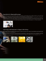
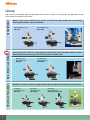
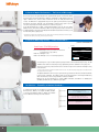
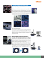
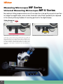
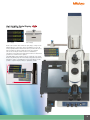
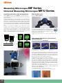
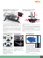
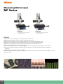

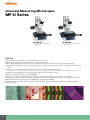
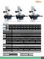
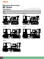
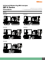
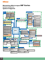
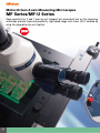
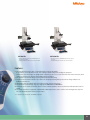
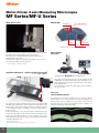
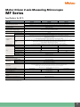
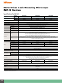
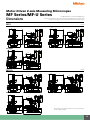
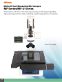
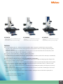
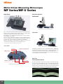
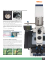
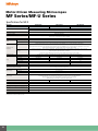
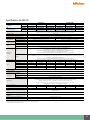
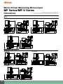
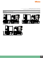
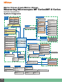

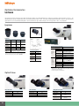
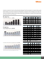
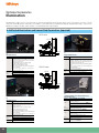
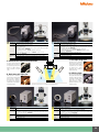
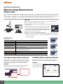
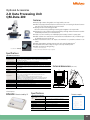
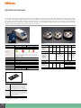
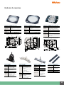
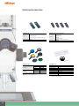
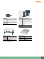
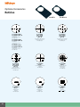
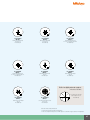


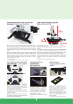
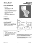
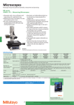

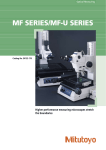
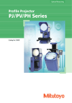
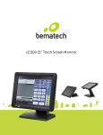
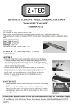
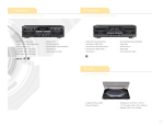


![8KG HEAT PUMP DRYER [Met DTD 315]](http://vs1.manualzilla.com/store/data/005851733_1-4b2b64d3b006b4e2563952fefa7cfd52-150x150.png)