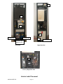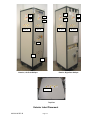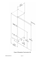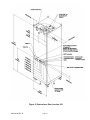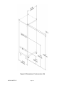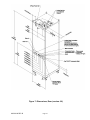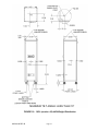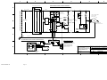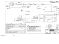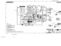
1
Customer Instruction Manual POLYCOLD CLOSED LOOP GAS CHILLER MODEL 1XCL-3-SE 440VAC Part # 700193-05 MODEL 1XCL-3-SE 2 440VAC Part # 700193-06 MODEL 1XCL-3-SE 2 480VAC Part # 700193-09 Serial # _____________ 825130-00 REV B Page 1 TABLE OF CONTENTS TABLE OF CONTENTS ................................................................................................................................ 2 1.0 INTRODUCTION ................................................................................................................................... 4 1.1 FOREWORD ............................................................................................................................. 4 1.2 SERVICE ............................................................................................................................. 5 1.4 HAZARD ALERTS INFORMATION .......................................................................................... 6 1.5 USER PRECAUTIONS............................................................................................................ 15 1.6 SAFETY INFORMATION ........................................................................................................ 17 1.7 SAFETY TRAINING GUIDELINES ................................................................................... 19 1.8 LOCK-OUT, TAG-OUT PROCEDURE.................................................................................... 20 2.0 INSTALLATION ................................................................................................................................... 21 2.1 SYSTEM DIAGRAMS.............................................................................................................. 21 Figure 3: System Block Diagram ............................................................................................... 23 Figure 4: Dimensions, Front (version -05) ................................................................................. 24 Figure 5: Dimensions, Rear (version -05) .................................................................................. 25 Figure 6: Dimensions, Front (version -06) ................................................................................. 26 Figure 7: Dimensions, Rear (version -06) .................................................................................. 27 2.2 ABOUT THE 1XCL .................................................................................................................. 28 2.3 INSPECT AND INSTALL THE 1XCL ................................................................................ 31 2.4 CONNECT THE COOLING WATER ....................................................................................... 41 2.5 INSTALL THE EXTERNAL GAS CIRCUIT AND GAS FILL LINE ........................................... 41 2.6 EMERGENCY OFF CIRCUIT ................................................................................................. 43 3.0 OPERATION ........................................................................................................................................ 43 3.1 INITIAL START-UP ................................................................................................................. 44 3.2 BAKE-OUT AND POST BAKE COOLING .............................................................................. 45 3.3 RESETTING SAFETY INTERLOCKS AFTER FAULT ........................................................... 45 4.0 INSPECTION & MAINTENANCE ......................................................................................................... 46 5.0 DISCONNECTION, STORAGE, AND RESHIPMENT ......................................................................... 48 6.0 TROUBLESHOOTING ......................................................................................................................... 49 GENERAL TROUBLESHOOTING MATRIX .................................................................................. 50 6.2 INDICATOR LAMPS BASED TROUBLESHOOTING MATRIX .............................................. 52 6.3 GAS COMPRESSOR UNIT (HC-8) FAULT MODES .............................................................. 57 6.4 AUTOFILL TROUBLESHOOTING BASICS ............................................................................ 60 6.5 AUTOFILL TROUBLESHOOTING MATRIX ..................................................................... 61 6.6 AUTO-FILL STATUS TABLES ................................................................................................ 62 6.7 AUTOFILL RELAYS AND SOLENOID VALVE ....................................................................... 63 6.8 ADJUSTING AUTO-FILL FILL CONTROL SETTINGS........................................................... 64 7.0 APPENDIX ........................................................................................................................................... 65 7.1 BRAZING SPECIFICATION .................................................................................................... 65 7.2 THERMOCOUPLE ATTACHMENT SPECIFICATION............................................................ 66 7.3 SPECIFICATIONS................................................................................................................... 67 7.4 DESIGN DATA ........................................................................................................................ 67 7.5 INSTRUCTIONS FOR INSTALLATION OF SEISMIC ANCHOR/JACK SCREWS ................ 68 8.0 GLOSSARY .......................................................................................................................................... 73 9.0 PROCESS & INSTRUMENTATION DIAGRAM AND ELECTRICAL SCHEMATICS .......................... 75 825130-00 REV B Page 2 ® ® Polycold® Systems Cooling Products, CryoTiger ,AquaTrap , Polycold Compact Cooler, Repair Services and Certified Refurbished Products Polycold® Systems cryogenic cooling products, including water vapor cryopumps (PFC, PCT, FLC, FI), chillers (PGC, PGCL), cryocoolers (P), CryoTiger, AquaTrap, Polycold Compact Cooler (PCC) and accessories, Certified Refurbished products (the “Products”) and Repair Service (i.e.- repairs other than warranty repairs) are warranted to be free from defects in materials and/or workmanship under normal service for the time period as set forth in Table A below from date of shipment from Brooks Automation, Inc. (“Brooks”). The warranty for Repair Service and Products is limited to the component parts replaced or repair performed by Brooks at Brooks’ facility. Customer is responsible for all charges and expenses for Brooks Services provided at Customer’s location by Brooks technicians as set forth in a quotation. Certified Refurbished Products and warranty exchange Products are remanufactured to like-new condition and contain used parts and materials. Table A Product New Product Warranty Repair Service Warranty Certified Refurbished Cryogenic Cooling Products Warranty Cryotiger® Products and Systems AquaTrap® Products and Systems Polycold® Compact Cooler (PCC) 15 Months 12 Months N/A Cryogenic cooling products, including: Water vapor cryopumps (PFC, PCT, FLC, FI), chillers (PGC, PGCL), cryocoolers (P), and accessories 24 Months 12 Months 12 months BROOKS MAKES NO OTHER REPRESENTATIONS OR WARRANTIES, EXPRESS OR IMPLIED, WITH RESPECT TO PRODUCTS OR SERVICES. UNLESS EXPRESSLY IDENTIFIED AS A WARRANTY, SPECIFICATIONS IN ANY PRODUCT DATASHEET CONSTITUTE PERFORMANCE GOALS ONLY, AND NOT WARRANTIES. BROOKS MAKES NO WARRANTY RESPECTING THE MERCHANTABILITY OF PRODUCTS OR THEIR SUITABILITY OR FITNESS FOR ANY PARTICULAR PURPOSE OR USE, OR RESPECTING INFRINGEMENT OF INTELLECTUAL PROPERTY RIGHTS. BROOKS DISCLAIMS ANY WARRANTY WITH RESPECT TO PRODUCTS MODIFIED WITHOUT BROOKS’ WRITTEN CONSENT, REPAIRS MADE OUTSIDE OF OUR FACTORY, PRODUCTS RENDERED DEFECTIVE BY CUSTOMER MISUSE, NEGLIGENCE, CORROSIVE ATMOSPHERES, ATTACK BY FREE CHEMICALS WITHIN THE SYSTEM, ACCIDENT, DAMAGE BY CUSTOMER OR CUSTOMER’S AGENT, OPERATION CONTRARY TO OUR RECOMMENDATION, IF THE SERIAL NUMBER HAS BEEN ALTERED, DEFACED OR REMOVED, THE USE OF SERVICE REPLACEMENT REFRIGERANTS FROM ANY THIRD PARTY NOT LICENSED BY BROOKS, OR THE PRODUCT IS OTHERWISE COMPROMISED BY USE OF UNAUTHORIZED PARTS OR SERVICE, ALL AS DETERMINED BY BROOKS IN ITS SOLE DISCRETION. IN NO EVENT WILL CUSTOMER BE ENTITLED TO, NOR WILL BROOKS BE LIABLE FOR INDIRECT, SPECIAL, INCIDENTAL, PUNITIVE OR CONSEQUENTIAL DAMAGES OF ANY NATURE, INCLUDING WITHOUT LIMITATION NEGLIGENCE, STRICT LIABILITY, OR OTHERWISE, ARISING AT ANY TIME, FROM ANY CAUSE WHATSOEVER, INCLUDING, WITHOUT LIMITATION, DOWN-TIME COSTS, DATA LOSS, DAMAGE TO ASSOCIATED EQUIPMENT, REMOVAL AND/OR REINSTALLATION COSTS, REPROCUREMENT COSTS, OR LOST PROFITS, EVEN IF BROOKS HAS BEEN ADVISED OF THE POSSIBILITY OF SUCH DAMAGES, AND EVEN IF THE LIMITED REMEDIES OF REPAIR OR REPLACEMENT FAIL OF THEIR ESSENTIAL PURPOSE. THIS WAIVER OF LIABILITY DOES NOT APPLY TO EITHER BROOKS’ LIABILITY UNDER A STATUTE, ACT OR LAW PERTAINING TO BODILY INJURY, OR TO ANY LIABILITY INCURING OUT OF DAMAGE TO THE BODY, HEALTH OR LIFE OF A PERSON. The exclusive remedies for breach of warranty will be either repair or replacement of the nonconforming parts or Products during the warranty period at the sole discretion of Brooks, shipped ExWorks (Incoterms 2000) Brooks factory. Customer’s recovery from Brooks for any claim shall not exceed the amount paid by customer to Brooks for the Product or Service giving rise to such claim, irrespective of the nature of the claim, whether in contract, tort, warranty, or otherwise. Customer must inspect the Products within a reasonable time upon receipt, and must notify Brooks within 30 days of discovering a defect. Every claim on account of defective material or workmanship shall be deemed waived unless made in writing within the warranty period specified above. Brooks does not assume, or authorize any other person to assume, any other obligations or liabilities in connection with the sale of the Products. All Polycold Products are also subject to the Brooks Automation, Inc. General Terms and Conditions, Polycold® Products, an excerpt of which is set forth above. ® Polycold is a registered trademark of Brooks Automation, Inc. Doc# PS-02 Rev D / January 26, 2006 3800 Lakeville Hwy • Petaluma, California 94954 U.S.A. • 707.769.7000 • Toll Free: 888.4.Polycold • Fax 707.769.1380 E-mail [email protected] • www.brooks.com 825130-00 REV B Page 3 1.0 INTRODUCTION 1.1 FOREWORD Polycold’s Cool Solutions® low temperature gas chillers are used to allow low temperature vacuum processing of semiconductor device wafers as well as other applications. Vacuum processing systems use recirculating fluids to keep the wafer at controlled temperature. The wafer sits on a pedestal or table in a vacuum and is processed, typically in a vacuum with specific gases and metallic vapors to create a uniform coating on it. Gas circulating in the secondary loop of the 1XCL closed loop gas chiller is cooled in the gas chiller. The temperature of the gas leaving the gas chiller can reach temperatures of –100oC. The chilled gas is recirculated by a secondary gas compressor. The customer-installed lines connecting the gas chiller and the pedestal are vacuum jacketed to minimize the heat leaks from the ambient to the chilled gas. The system consists of a refrigeration system, which chills the secondary gas, a secondary gas recirculating compressor, interconnecting gas lines and the table in the vacuum system. The refrigeration system uses a propriety and patented blend of refrigerants. The secondary loop compressor uses an inert gas whose dew point is below –80oC. The refrigeration system as well as the secondary gas loop requires cooling water. There is no co-mixing of the refrigerant and the secondary gas. The equipment is designed for continuous operation. Electricity, cooling water, and pressurized dry nitrogen are the only required utilities. Pressures are stated as gauge, not absolute. Psig is pounds per square inch gauge and kPa is Kilopascals gauge. kPa = 6.895 x Psig bar = Psig 14.5 This technical manual contains Safety, Service, Introduction, Specifications, Installation, Operation, Maintenance, and Parts information for all the equipment in the system. Notes: REVIEW THE INSTRUCTION MANUAL BEFORE OPERATING THIS EQUIPMENT! This unit was shipped with a shipping bolt to secure the compressor for transport. It must be removed to prevent excess vibration. Failure to do so may void your warranty. Before shipping this unit the shipping bolt must be re-installed to prevent damage during shipping. Failure to do so may void your warranty. Refer to section 2.3, Item 3. Upon arrival of the equipment and prior to starting its installation or operation confirm that the balance pressure (BP) shown on the suction pressure gauge is between 140 – 160 psi. Refer to section 2.3, Item 2. 825130-00 REV B Page 4 1.2 SERVICE Information provided within this document is subject to change without notice, and although believed to be accurate, Brooks Automation assumes no responsibility for any errors, omissions, or inaccuracies. AcuLigner, AcuLine, AcuTran, AcuTrav, AeroLoader IV, AeroTrak, ARV 2000, AquaTran, Atmospheric Express, BALI 400 Indexer, BiSymmetrik, ExpressLock, FabExpress, FixLoad, FrogLeg, Gemini, Gemini Express, Gemini Express Tandem, Guardian Bare Reticle Stocker, Hercules, Hercules Express, InCooler, InLigner, InLine Express, Leapfrog, Linear eXchange, MagnaTran 7, MagnaTran 70, MagnaTran 8, MagnaTran X, Marathon, Marathon Express, Marathon Express Tandem, MicroTool, MultiTran, OneFab AMHS, OpenMTS, PASIV, PF-100, PowerPak, Reliance ATR, Reliance DFR, Reliance WCR, SENTRY, TCM, Time Optimal Trajectory, TopCooler, TurboStocker, TurboStocker XT, Ultrasort, VacuTran, VCD, VCE, VPE, WAVE, WAVE II, Zaris, Z-Bot, Aquatrap, Conductron, Convectron, Cool Solutions, Cryodyne, Cryogem, Cryogenerator, CryoTiger, Cryo-Torr, CTI-Cryogenics, FastRegen™, GOLDLink, Granville-Phillips, GUTS, Helix, Micro-Ion, Mini-Convectron, Mini-Ion™, On-Board, Polycold, RetroEase, RetroFast, Stabil-Ion, ThinLine™, TrueBlueSM, TurboPlus, and Vacuum AssuranceSM are trademarks of Brooks Automation Hardware. All other trademarks are properties of their respective owners. © Brooks Automation 2006, All Rights Reserved. The information included in this manual is Brooks Proprietary Information and is provided for the use of Brooks customers only and cannot be used for distribution, reproduction, or sale without the expressed written permission of Brooks Automation. This information may be incorporated into the user’s documentation, however any changes made by the user to this information is the responsibility of the user. Brooks Automation 15 Elizabeth Drive Chelmsford, MA 01824 Phone +1 (978) 262-2400 Fax +1 (978) 262-2500 For emergencies, contact Technical Support +1 (978) 262-2900 www.brooks.com This manual is available in the following languages: English. This technology is subject to United States export Administration Regulations and authorized to the destination only; diversion contrary to U.S. law is prohibited. Printed in the U.S.A. © 2006 by Brooks Polycold Systems Inc. All rights reserved. Printed in the United States of America. Trademark Recognition:Armaflex® is a registered trademark of Armstrong World Industries, Inc. CPI UltraSeal™ is a trademark of Parker Hannifin Corporation. Phillips® is a registered trademark of Phillips Screw Company. Polycold® is a registered trademark of Brooks Technology Corporation. VCR® is a registered trademark of Cajon Company. is a registered trademark of Brooks Technology Corporation. 1.3 BEFORE YOU START Please have the following information available to help us assist you: Polycold Model: __________________________ Polycold Serial No: ________________________ Date Manufactured: ________________________ The above information is on the nameplate of your 1XCL. You may wish to enter this information now (before the 1XCL is installed). 825130-00 REV B Page 5 1.4 HAZARD ALERTS INFORMATION VISUAL HAZARD ALERTS USED IN THIS MANUAL AND AS LABELS ON THE EQUIPMENT SHOULD BE REVIEWED AND UNDERSTOOD BY PERSONNEL PRIOR TO USE OF THE SYSTEM. Hazard warnings are provided in this manual before each step that may involve hazards to personnel. See the following hazard alert icons and text for information on icons, which identify potentially hazardous situations/consequences of not avoiding the hazard. Hazard alerts used in the manual and on the equipment follow ANSI Z535 and use the signal words DANGER, WARNING or CAUTION. The signal words have the following meanings: WARNING ELECTRICAL HAZARD High Voltage can cause severe injury or death. Disconnect power before removing access panels HAZARD KEYWORD LEVELS DANGER An imminently hazardous situation that, if not avoided, will result in serious injury or death. WARNING A potentially hazardous situation that, if not avoided, could result in severe injury or death. CAUTION A potentially hazardous situation that, if not avoided could result in moderate or minor injury or property or equipment damage. Hazard Warning Labels Identified by Number 1. CAUTION 825130-00 REV B Page 6 2. WARNING 3. CAUTION 4. ATTENTION 5. CAUTION 825130-00 REV B Page 7 6. ATTENTION 7. WARNING 825130-00 REV B Page 8 8. CAUTION 9. SEISMIC ANCHOR P0INT 825130-00 REV B Page 9 10 11 REVIEW THIS INSTRUCTION MANUAL BEFORE STARTING THIS EQUIPMENT. 1. Before starting this equipment, record this pressure (refrigerant suction). When the refrigeration compressor is off, the normal range is 140 – 175 psi (9.6 – 12.1 bar). Lower pressures may be observed if the unit was operated in the last 24 hours and is still cold. Lower pressures when the unit is at room temperature can still provide adequate cooling performance. 2. There will be a delay of up to 2 minutes before the refrigeration compressor starts. After this delay, observe that the refrigerant suction gage pressure decreases to approx 20 psi (1.4 bar) during the first minute. If the pressure remains high turn off the unit and consult Polycold service. 12 P/N 407161-00 WARNING TIPPING HAZARD, HIGH CENTER OF GRAVITY, LESS THAN 10º MAX TILT ANGLE Over tipping (leaning) this device may cause it to fall over resulting in severe injury or death. Read the manual before moving this equipment using the casters. Move the equipment on level floors only. Move it slowly and avoid rapid acceleration and deceleration. Apply force to move the system below the equipment center of gravity. Do not place yourself between the moving equipment and fixed obstructions. Once equipment is installed, securely fasten frame to floor. 825130-00 REV B Page 10 13 14 825130-00 REV B Page 11 2 2 2 5 9 (version -06) 9 (version -06) 2 9 (version -05) 9 (version -05) 14 (version -06) Front View Right Side View 8 Close-up Right Side View Interior Label Placement 825130-00 REV B Page 12 3, 2, 5 5 4 7 9 (version -06) 9 (version -06) 9 (version -05) 9 (version -05) 14 (version -06) Rear View Left Side View 2 Top View Interior Label Placement, Continued 825130-00 REV B Page 13 11 11 11 11 13 13 13 2, 1, 3 2, 1, 3 2, 1, 3 13 2, 1, 3 12 6 10 Exterior, Left Front Oblique Exterior, Right Rear Oblique 2, 1, 3 Top View Exterior Label Placement 825130-00 REV B Page 14 1.5 USER PRECAUTIONS CAUTION! REVIEW THE INSTRUCTION MANUAL BEFORE PERFORMING ANY PROCEDURE OTHER THAN THE ROUTINE OPERATION OF THE 1XCL. Performance of procedures other than those specified herein may result in hazardous exposures to electrical, ultra-low temperature or moving parts hazards. Additional precautions are located in the appropriate section of this manual CAUTION! THE 1XCL CONTAINS PRESSURIZED GAS. DO NOT OPEN THE REFRIGERANT CIRCUIT TO THE ATMOSPHERE. All refrigeration work must be performed by qualified Type 2, High Pressure refrigeration technicians. Do not loosen any valve packing or fittings unless you are specifically following the instructions in the recharge procedure. Discharge of refrigerant may cause personal injury due to high pressures or ultra-low temperatures. In addition, if refrigerant is lost, the 1XCL may need to be recharged before it can be used. WARNING! HAZARDOUS VOLTAGE EXISTS AT ALL TIMES AFTER THE POWER IS CONNECTED. Only qualified electricians should perform electrical work. Power should be removed at the point of electrical connection, and locked out following standard lockout tag-out procedures. A lockout device may be placed on the supply power circuit breaker (provided by others) or on the supplied electrical power plug. DANGER! DO NOT REACH INSIDE THE 1XCL WHEN IT IS OPERATING. The unit contains hazardous voltages and extreme temperatures. DANGER! DO NOT TOUCH AN UNINSULATED GAS LINE OR THE EXITING GAS STREAM WHEN THE 1XCL IS OPERATING. The system circulates gas at ultralow temperatures, which on contact with skin presents the risk of frostbite. CAUTION! MAKE CERTAIN THERE IS ADEQUATE VENTILATION AROUND THE 1XCL, ESPECIALLY IF YOU ARE RECHARGING IT. Modern refrigeration practice is to reclaim and recycle the refrigerant. (Do not put the refrigerant back into the 1XCL, however.) CAUTION! IN THE EVENT OF A FAILURE OF THE REFRIGERANT UNIT PIPING, REFRIGERANT COULD BE RELEASED OUTSIDE THE 1XCL ENCLOSURE INTO THE ROOM ENVIRONMENT. 825130-00 REV B Page 15 WARNING! LIFTING HAZARD (900 pounds (400 kg)) Failure to properly lift this device may result in severe injury or death Read the manual before lifting this equipment using the lifting eyes. Assure that the eyes are fully engaged in the frame with no exposed threads. Use all four lifting eyes with an adequate lifting harness and mechanism. Lifting harness must be centered between the lifting eyes. Lift vertically only with no horizontal component. WARNING! TIPPING HAZARD, HIGH CENTER OF GRAVITY, LESS THAN 10º MAX TILT ANGLE Over tipping (leaning) this device may cause it to fall over resulting in severe injury or death. The equipment should be removed from its shipping pallet by using the top installed lifting eyes. WARNING! TIPPING HAZARD, HIGH CENTER OF GRAVITY, LESS THAN 10º MAX TILT ANGLE Over tipping (leaning) this device may cause it to fall over resulting in severe injury or death. Read the manual before moving this equipment using the casters. Move the equipment on level floors only. Move it slowly and avoid rapid acceleration and deceleration. Apply force to move the system below the equipment center of gravity. Do not place yourself between the moving equipment and fixed obstructions. CAUTION! THIS SYSTEM PRODUCES AND CIRCULATES COLD GAS AT TEMPERATURES AS LOW AS - 110º C. Assure that integrating systems and components are suitable for rapid exposure to these low temperatures. WARNING! TIPPING HAZARD, HIGH CENTER OF GRAVITY, LESS THAN 10º MAX TILT ANGLE Maintain weight on casters at all times. 825130-00 REV B Page 16 1.6 SAFETY INFORMATION Safety Hazards and Safeguards NOTE: The user is advised to retain current copies of material safety data sheets (MSDS) for refrigerants and cleaning agents used in the operation and maintenance of this equipment. One copy of the MSDS for the system refrigerant has been attached to this user’s manual. Safety Devices incorporated in the 1XCL and their function is described below: REFRIGERATION COMPRESSOR UNIT Descriptor PS1 Name Function A high-pressure switch is incorporated in the discharge side of the compressor. The switch opens contacts if the refrigerant pressure exceeds normal operating pressure, interrupting power to the compressor and turning it off. This switch requires manual reset. The user should not adjust it. High Pressure Switch FP1 Fusible Plug (located on expansion tank) A fusible plug is installed in the discharge plumbing of the compressor and serves as the controlled release point for refrigerant should a fire occur in the area of the 1XCL. The fusible plug provides a means to reduce high pressures caused by excessive ambient temperatures in a manner that does not result in an explosion. HTS/TS1 High Temperature Switch A high temperature switch is coupled to the condenser refrigerant side. In the event that the condenser is obstructed or flow is otherwise interrupted, the refrigerant temperature will rise, opening the contacts on the high temperature switch. This removes power from the compressor and turns it off. This switch requires manual reset. The user should not adjust it. Schematic representations of safety device locations may be found in the Process and Instrumentation Diagram and on the Electrical Diagrams. GAS COMPRESSOR UNIT PS2 Low Pressure Switch A low-pressure switch is incorporated in the suction side of the gas compressor. The switch opens contacts if the gas pressure drops below normal operating pressure, interrupting power to the compressor and turning it off. This switch is auto-reset. The user should not adjust it. PS3 High Pressure Switch A high-pressure switch is incorporated in the discharge side of the gas compressor. The switch opens contacts if the gas pressure exceeds normal operating pressure, interrupting power to the compressor and turning it off. This switch requires venting of nitrogen to 0 psi and manual reset. The user should not adjust it. TS2 Oil High Temp Pressure Switch TS3 Compressor Shell High Temperature Switch TS4 Gas High Temperature Switch A high temperature switch shuts off the gas compressor when excessive oil temperature causes it to function. The compressor automatically restarts after the temperature cools and the switch resets. A high temperature switch shuts off the gas compressor when excessive shell temperature causes it to function. The compressor automatically restarts after the temperature cools and the switch resets. A high temperature switch shuts off the gas compressor when excessive gas temperature causes it to function. The compressor automatically restarts after the temperature cools and the switch resets. 825130-00 REV B Page 17 CAUTION! Safety devices are installed on the 1XCL to help protect it from permanent damage. Some of the protective devices are self-resetting, with a system status output to the integrating equipment. When the system status indicates that a safety component has functioned, the integrating equipment should not enable operation until the cause of the fault is corrected. If a protective device is triggered, the cause of the problem must be corrected before continuing to use the 1XCL. Please see Section 6.0 “Trouble-Shooting” or call the Polycold Service Department for assistance. Bypassing or repeated resetting of a protective device may expose personnel and or the facility to hazards, permanently damage the equipment, and may void your warranty. TABLE A CIRCUIT BREAKER AND FUSE PROTECTION Reference Designation CB2 Protection Provided Over current Rated Voltage And Amperage 230V 20A Amperage Interrupting Capacity 2,500 (See Note) CB1 Over current 230V 25A 1,500 CB3 Over current 230V 2A 6,000 FU1 on Power Supply 1 FU2 on Power Supply 2 (PS2) Over current 230V 2AT Over current 230V 2AT Note: Your electrical supply must also have enough capacity to handle the Rated Load Amps and should be provided through a circuit breaker rated with at least 10,000 AIC. 825130-00 REV B Page 18 1.7 SAFETY TRAINING GUIDELINES The safety information in this chapter is a summary of the safety information that is to be successfully conveyed to service personnel as part of their training on the POLYCOLD GAS CHILLER 1XCL. The training program is intended to ensure that any person who undertakes the service of the 1XCL can demonstrate competence to perform the required tasks safely. Accordingly, training required for each task includes, but is not limited to, the following: 1. A review of applicable safety standards and procedures as well as those presented in this chapter. 2. A review of maintenance and safety recommendations applicable to vendor supplied equipment. 3. An explanation of the purpose of subsystems and their operation. 4. An explanation of the specific tasks and responsibilities of each person (operator, service personnel, etc.) assigned to the Polycold GAS Chiller 1XCL equipment. 5. The person(s) (identified by name, location and telephone number) to be contacted when required actions are beyond the training and responsibility of the person being trained. 6. Identification of the recognized hazards associated with each task. 7. Identification of, and appropriate responses to, unusual operating conditions. 8. Explanation of the functions and limitations of all safeguards, and their design characteristics. 9. Instructions for the functional testing (or other means of assurance) for proper operation of safeguarding devices. 10. Service personnel should understand the operation of process-related hardware interlocks, and the sequences of hardware operation that are executed automatically, as explained in this chapter. 11. The equipment should not be used without assuring correct operation of all connected facilities, especially fugitive emissions exhaust. 12. Service personnel should always assume that high voltage is present unless they have personally turned it off and locked it out. 13. The equipment should not be operated without all guards and safety devices in place. 14. The equipment should be shut down, locked out, and not operated while it is being maintained. 15. Users should not attempt to defeat, modify or disable any of the equipment’s safety interlock switches. 16. Only Brooks Automation trained service personnel should perform assembly, operation, disassembly, service or maintenance of the Polycold GAS Chiller 1XCL equipment. A certified refrigeration technician must perform any work performed on the refrigeration portion of the system. 17. All safety related incidents or near misses should be reported to a supervisor or Brooks Automation Customer Service. 18. The user should carefully review and understand manufacturer provided material safety data sheets (MSDS) for materials used by this equipment. 825130-00 REV B Page 19 1.8 LOCK-OUT, TAG-OUT PROCEDURE LOCK-OUT TAG-OUT PROCEDURE, ELECTRICAL 1. Notify personnel you are performing a Lock-Out Tag-Out (LOTO) 2. Shut down system following normal procedure: Remove power to the 1XCL, verify that the compressor is off. 3. Isolate the system from the electrical supply by locking-out the breaker in the “off” position and notifying others with an identification tag. 4. De-energize the unit’s internal capacitors. A qualified and trained technician must execute this procedure. If the unit’s power plug is accessible, connect a 10KΩ bleed resister between the L1 pin and Ground pin of the plug, then connect the bleed resistor between L2 pin and the Ground pin. It may be necessary to discharge the capacitors directly by connecting a 10KΩ resister from each capacitor terminal to ground. The capacitors are located inside the electrical enclosure. See figure below. 5. Use a voltmeter to observe “0” volts in the area you will be working. Service can now be performed. 6. To re-energize, reverse these steps. LOCK-OUT TAG-OUT PROCEDURE, GAS SUPPLY 1. Notify personnel you are performing a Lock-Out Tag Out (LOTO) 2. Isolate the system from the gas supply by closing the customer supplied gas connectors. 3. Verify the system is locked-out by slowly opening the gas inlet fitting on the 1XCL unit and allow the pressure to bleed down for 2 minutes—the flow should gradually slow to a stop. 4. Add lock and notification Tag to supply source shutoff. 5. To re-establish gas supply, reverse these steps. 825130-00 REV B Page 20 2.0 INSTALLATION 2.1 SYSTEM DIAGRAMS See Section 9 for Process & Instrumentation Diagram and Electrical Schematics 825130-00 REV B Page 21 Figure 2: Electrical Distribution Diagram (440, 460, 480VAC, 50/60Hz, 3Ø, 16A) 825130-00 REV B Page 22 Figure 3: System Block Diagram 825130-00 REV B Page 23 Figure 4: Dimensions, Front (version -05) 825130-00 REV B Page 24 Figure 5: Dimensions, Rear (version -05) 825130-00 REV B Page 25 Figure 6: Dimensions, Front (version -06) 825130-00 REV B Page 26 Figure 7: Dimensions, Rear (version -06) 825130-00 REV B Page 27 2.2 ABOUT THE 1XCL 1. What it is and what it does Polycold’s Cool Solutions® 1XCL is a refrigeration unit that cools a stream of gas to ultra-low temperatures. It consists of two separate subsystems, the upper portion known as the Refrigeration Unit, which provides the cooling of the gas stream and the lower portion, which provides the secondary loop circulation of the gas stream. The Refrigeration Unit has a refrigerant circuit and a gas circuit. The refrigerant circuit is located entirely within the 1XCL. The 1XCL‘s compressor circulates refrigerant in a continuous loop through the Polycold stack. The water-cooled condenser removes the heat of compression from the refrigerant by circulating cooling water through a coaxial coil, and the Polycold stack cools the refrigerant to ultra-low temperatures. (The refrigerant is a proprietary mixture of refrigerants provided by Brooks Automation.) The gas circuit consists of a continuous copper tube that runs through the refrigerant circuit. The gas is cooled as it runs through the Polycold stack. The gas compressor compresses customer supplied nitrogen or helium gas and uses a heat exchanger to cool it to room temperature. Oil separators and an oil adsorber reduce levels of oil and moisture in the gas stream to very low levels. A regenerative heat exchanger is used to assure that low pressure gas entering the compressor is within design limits of the gas compressor. High pressure gas exiting the regenerative heat exchanger enters the Polycold stack. When the Polycold stack is cold, it chills the high pressure gas being supplied to the customer process. Low pressure gas returning from the process passes through the regenerative heat exchanger before entering the gas compressor. 825130-00 REV B Page 28 2. The 1XCL features (refer to the figures below) 11 25 11 11 11 23 24 2 7 6 See Detail Below 33 4 5 9 8 13 1 10 35 3 31 14 34 32 12 FRONT VIEW REAR VIEW 19 20 21 17 22 13 14 15 16 18 REAR VIEW DETAIL 3. Unit Features: 1 MAIN ON/OFF ROCKER SWITCH Gas Compressor Unit (HC-8) (CB1): This switch starts the gas compressor unit. After initial startup, switch must remain in the ON position if unit functions are to be accessed remotely. 2 MAIN ON/OFF ROCKER SWITCH Refrigeration Unit (CB2): This switch starts the Refrigeration unit. After initial startup, ON/OFF functions of the unit may be accessed remotely. 825130-00 REV B Page 29 3 RUN INDICATOR HC-8: Will be illuminated when line voltage and user interface signals are present and CB1 is closed and the compressor contactor is closed. 4 RUN INDICATOR, Refrigeration Unit: Will be illuminated when power is applied, the rocker switch is in the on “I” position and all systems are operating normally indicating that the compressor contactor is closed (green LED). 5 FAULT INDICATOR, Refrigeration Unit: Will illuminate if a problem such as overpressures or temperature fault should occur. Refrigeration Unit and Gas Compressor Unit (HC-8): Illuminates when line voltage is present and Gas Compressor circuit breaker (CB1 is closed) (red LED). 6 LINE INDICATOR, Refrigeration Unit and Gas Compressor Unit (HC-8): Illuminates when line voltage is present (yellow LED). 7 EMO (emergency machine off) BUTTON: Used to power down the unit(s) in the event an emergency situation should occur. This circuit is wired to a dedicated safe voltage supply and if activated all unit functions will cease and cause power contactors to open with the exception of power to this circuit. This button latches in the off position and must be rotated clockwise to disengage. Hazardous voltages remain in the unit from the point of electrical connection to the line side of the compressor contactors. The customer is responsible for removing power from the Polycold unit supply when the EMO circuit is activated. 8 RECIRCULATING GAS SUPPLY GAUGE: This dial represents supply pressure from the Gas Compressor Unit (HC-8) portion of the cooling unit to the host equipment. During normal operation, the dial typically reads 85 - 115 PSI. 9 REFRIGERANT SUCTION GAUGE: This dial represents internal Refrigeration Unit pressure (suction). During normal operation, the dial typically reads 25-35 PSI. 10 SEISMIC ATTACHMENT POINTS: These (4) 3/8-16 NC threaded barrels are provided for seismic anchoring and can be used to install seismic anchor/jack screws. 11 LIFTING EYES: These (4) lifting eyes are provided as an accessory to safely lift the unit into place. These eyes are mounted in 3/8-16 NC threaded barrels. WARNING! LIFTING HAZARD (900 pounds (400 kg)) Failure to properly lift this device may result in severe injury or death Read the manual before lifting this equipment using the lifting eyes. Assure that the eyes are fully engaged in the frame with no exposed threads. Use all four lifting eyes with an adequate lifting harness and mechanism. Lifting harness must be centered between the lifting eyes. Lift vertically only with no horizontal component. 12 CASTERS: Enable the unit to be rolled into place for installation and for maintenance, etc. 13 WATER IN CONNECTION: ½ FNPT connection. 14 WATER OUT CONNECTION: ½ FNPT connection. 15 EMO LOOP J1 CONNECTOR: This is the FEMALE connector that allows access to the dedicated emergency machine off circuitry. It is wired in SERIES with the EMO button. 16 EMO LOOP J2 CONNECTOR: This is the MALE connector that allows access to the dedicated emergency machine off circuitry. It is wired in SERIES with the EMO button. 17 VENT VALVE: (V7) This valve is piped to the high-pressure side of the HC-8 compressor. 18 REMOTE CONNECTOR: This connector provides switch contact opening for status of refrigeration and gas compressor units. 19 THERMOCOUPLE CONNECTOR: Miniature Type K, Supply temperature OUT 20 THERMOCOUPLE CONNECTOR: Miniature Type K, Temperature return 825130-00 REV B Page 30 21 THERMOCOUPLE CONNECTOR: Spare 22 FILL VALVE: This is a ¼” compression fitting, used for charging the coolant loop. It is connected to a check valve to prevent pressurized gas from releasing through this fitting when it is open. It is piped to the suction side of the compressor. See fill procedures. 23 GAS SUPPLY: Bayonet adapter fits here, ½ Parker Ultraseal x Linde ½ 24 GAS RETURN: Bayonet adapter fits here, ½ Parker Ultraseal x Linde ½ 25 POWER INLET: Liquid tight conduit fitting, diam.: 1”, 2.45” (L) x 1.88” (W) 31 AUTO FILL CONTROL (PS 4): This display shows the gas suction pressure. It also is used to adjust settings for the auto fill controller. 32 FILL POWER SWITCH: This switch is used to enable or disable the auto fill controller. 33 FLOW INDICATING METER: Indicates that gas flow is occurring. Scale readings are not accurate for the nitrogen gas used. 34 GAS VENT VALVE WRENCH: This wrench is provided to open and close the gas vent valve (V7). 35 REMOTE JUMPER: This is used to simulate the remote interface “go” signals for the refrigeration chiller and the gas compressor unit. This jumper allows the 1XCL to be operated without being connected to the tool’s remote user interface. 2.3 INSPECT AND INSTALL THE 1XCL CAUTION! No operator serviced parts within. Access restricted to trained service personnel only. Review specifications table (7.3) for facility requirements prior to installation. Tools and materials needed: 1. Fork Lift (for overhead lift only), Pallet truck or Overhead Crane 2. Power plug to fit your power supply outlet (On 208V unit provide receptacle for equipment provided cord and plug assembly. On 480V unit provide attachment plug and cord to equipment mounted Hubble HBL2733 receptacle). 3. Wire stripper 4. #2 Phillips head screwdriver 5. 11/16 inch socket wrench for shipping bolt 6. ½ inch box wrench for 1-3/8 inch freeze plug 1. Inspect the 1XCL crate for damage and document any visible damage. 2. Open the crate and inspect the 1XCL. Notify the carrier immediately if you suspect the 1XCL was damaged during shipping. Read the dial of the RECIRCULATING GAS SUPPLY GAUGE and record the pressure: ________ psig. Read the dial of the REFRIGERANT SUCTION GAUGE and record the pressure:____psig. 825130-00 REV B Page 31 3. Determine if the Seismic anchor/jack screws are installed. If not, install the seismic anchor/jack screws per the procedure shown in 7.5. 4. Remove the 1XCL from the crate using the top mounted lifting eyes. WARNING! LIFTING HAZARD (900 pounds (400 kg)) Failure to properly lift this device may result in severe injury or death Read the manual before lifting this equipment using the lifting eyes. Assure that the eyes are fully engaged in the frame with no exposed threads. Use all four lifting eyes with an adequate lifting harness and mechanism. Lifting harness must be centered between the lifting eyes. Lift vertically only with no horizontal component. WARNING! TIPPING HAZARD, HIGH CENTER OF GRAVITY, LESS THAN 10º MAX TILT ANGLE Over tipping (leaning) this device may cause it to fall over resulting in severe injury or death. The equipment should be removed from its shipping pallet by using the top installed lifting eyes. WARNING! TIPPING HAZARD, HIGH CENTER OF GRAVITY, LESS THAN 10º MAX TILT ANGLE Over tipping (leaning) this device may cause it to fall over resulting in severe injury or death. Read the manual before moving this equipment using the casters. Move the equipment slowly and avoid rapid acceleration and deceleration. Apply force to move the system below the equipment center of gravity. Do not place yourself between the moving equipment and fixed obstructions. 5. Install 1XCL . (See Appendix 7.5). WARNING! Due to its weight, a lift truck or overhead crane is required to place and remove the 1XCL from the transport unit. WARNING! Due to its high center of gravity, care must be taken to avoid tipping the unit. 1) During transporting the pallet to which the unit is strapped and 2) positioning on its casters. See illustration figures 4 & 5. The 1XCL should only be lifted from above, using its lifting eyes and a sling system. Place the 1XCL as close as possible to the desired location of your cold GAS stream. The 1XCL must remain vertical during transport and installation. The base frame of the 1XCL can be secured to the floor at the four locations labeled Seismic Anchor Point. See section 6 for mounting dimensions. 6. Move the 1XCL Unit to Its Installation Location The 1XCL Unit should be moved to an area near its installation location using the top mounted lifting eyes and slings. The 1XCL unit may be transported short distances on level floors within the installation location on its casters. DO NOT MOVE THE UNIT UP OR DOWN RAMPS ON ITS CASTERS! WARNING! TIPPING HAZARD, HIGH CENTER OF GRAVITY, LESS THAN 10º MAX TILT ANGLE Over tipping (leaning) this device may cause it to fall over resulting in severe injury or death. Read the manual before moving this equipment using the casters. Move the equipment on level floors only. Move it slowly and avoid rapid acceleration and deceleration. Apply force to move the system below the equipment center of gravity. Do not place yourself between the moving equipment and fixed obstructions. 825130-00 REV B Page 32 WARNING! TIPPING HAZARD, HIGH CENTER OF GRAVITY, LESS THAN 10º MAX TILT ANGLE Maintain weight on casters at all times. Figure 8: 1XCL “Footprint” 825130-00 REV B Page 33 FIGURE 9: 1XCL (version -05) 440V Weight Distribution 825130-00 REV B Page 34 FIGURE 10: 1XCL (version -06) 440V Weight Distribution 825130-00 REV B Page 35 7. Shipping Bolt Removal There is a bolt at the base of the lower compressor that has been provided to protect the compressor from damage during shipping. Do Not operate the unit with this shipping bolt in place. Verify that the bolt has been removed prior to initial start-up. The shipping bolt must be removed from the base of the compressor prior to starting the unit. This is located on the underside of the base pan. A rubber plug has been supplied for the purpose of sealing the access hole so that the pan will act as a catch basin. Save this plug and the bolt for later use. It is required that the shipping bolt be replaced in the event that the unit is reshipped to another location. REVIEW THE INSTRUCTION MANUAL BEFORE OPERATING THIS EQUIPMENT! This unit was shipped with a shipping bolt to secure the compressor for transport. It must be removed to prevent excess vibration. Failure to do so may void your warranty. Before shipping this unit the shipping bolt must be re-installed to prevent damage during shipping. Failure to do so may void your warranty. 8. Connect the electrical power. WARNING! HAZARDOUS VOLTAGES Electrical power to the 1XCL must be connected by qualified personnel, according to local codes. WARNING! HAZARDOUS VOLTAGE EXISTS AT ALL TIMES AFTER THE POWER IS CONNECTED. Only qualified electricians should perform electrical work. Power should be removed at the point of electrical connection, and locked out following standard lock-out tag-out procedures. A lock-out device may be placed on the supply power circuit breaker (provided by others) or on the supplied electrical power plug. The host equipment is to provide the main disconnect device and a circuit breaker that serves as the overcurrent protection for the electrical supply circuit. Before connecting the 1XCL to your power source, verify the following: The disconnect device is readily accessible to the operator; located in sight and within 25’ of the 1XCL; and clearly marked to indicate the equipment that it protects. The disconnect device locks in the de-energized position only; complies with IEC 947-1 and 947-3 standards; and meets the requirements of SEMI S2 section 17. Your actual voltage falls within the acceptable range listed in Table B. 825130-00 REV B Page 36 Your electrical supply has enough capacity to handle the Rated Load Amps and is provided through a circuit breaker rated with at least 10,000 AIC. The circuit protection must be adequately sized to operate with the 10 AWG internal wiring of the circuit. The supply power wiring must be sized in accordance with NFPA 79. The 1XCL is grounded according to SEMI S2 and CE requirements. Note: The 1XCL is intended to be a subsystem of equipment and requires incorporation and protection by the host equipment Emergency Off (EMO) circuit. Refer to Electrical Schematic. TABLE B Nominal Voltage Voltage/Phase/ Cycles Acceptable Voltage Range FLA Fuse Size 440V 440/3Ø/60 396V- 484V 13.2A 16A 480V 480/3Ø//50/60 432V- 528V 12A 16A CAUTION! Phase sensitive equipment. Clockwise rotation required. Incorrect rotation will prevent equipment operation. The 1XCL is phase-sensitive and will not function if wired incorrectly. If you are uncertain of the phase rotation of your power source, you can confirm that the phase protection relay is satisfied (amber and green LEDs are illuminated) prior to completing electrical fit-up of the system (see section 6.6). CAUTION! Status on Power Interruption/Restoration The 1XCL system is not configured with onboard main circuit breaker. In the event of power interruption, the 1XCL ceases operation. On restoration of electrical power, the 1XCL system will restart when provided an enable signal. Placing the equipment in a safe shut down condition requires removing the 1XCL Main Power cord connector. Power Cord Installation 1. Remove top panel of the 1XCL unit. 2. Using a 5/16” nut driver or socket drive, remove the nuts from the plastic guard on the terminal block. 3. Remove the plastic guard from the terminal block (see photo below). 825130-00 REV B Terminal Block with Plastic Guard Page 37 Note: Use 10 AWG wire for your power cord. 4. Insert power cord through the liquid tight fitting located on the back-side of the 1XCL unit (see label 1 below). 1 Power Inlet 5. Connect power cord to terminal block using the #10-32 screws provided. 6. Tighten screws on the terminal block using a torque wrench set to 20 IN-LBS. 7. Connect ground wire to terminal lug labeled “PE” (potential earth)/ “GND” and tighten screws securely (see photo below). Terminal Block with Power Cord Connected 8. Re-install plastic guard (see photo below). Terminal Block with Power Cord Connected and Plastic Guard Installed 825130-00 REV B Page 38 9. Installation of seismic anchorage brackets Make sure seismic anchor/jack screws are installed (See Appendix 7.5 for more information). Install SEMI S2 approved seismic anchorage brackets. Install seismic anchorage brackets that secure the seismic anchor/jack screw firmly to the facility floor. Seismic anchorage brackets must be suitable to withstand a seismic load of 1400 lbs. per SEMI S2 requirements. (See semi.org for more information on S2 requirements.) WARNING! TIPPING HAZARD, HIGH CENTER OF GRAVITY, LESS THAN 10º MAX TILT ANGLE Maintain weight on casters at all times. 10. 1XCL Safety Circuit Connector WARNING! THIS UNIT MUST BE WIRED INTO THE CUSTOMER’S SAFETY CHAIN. HAZARDOUS VOLTAGE EXISTS AT ALL TIMES AFTER THE POWER IS CONNECTED. Only qualified electricians should perform electrical work. Power should be removed at the point of electrical connection, and locked out following standard lock-out tag-out procedures. A lock-out device may be placed on the supply power circuit breaker (provided by host) or on the supplied electrical power plug. The safety circuit connector provides two distinct functions. The first being pressure switch fault status, either high (discharge side) or low (suction side) pressure, the second being remote monitoring of the thermostat switches coupled to the discharge and liquid line temperatures. 11. 1XCL Thermocouple Connectors The type k thermocouple connector provides remote temperature monitoring of the refrigerant temperature as it leaves the evaporator and the discharge temperature of the compressor. RETURN - Measures the nitrogen temperature returning to the 1XCL from the customer process SUPPLY - Measures the temperature of the nitrogen supplied by the 1XCL SPARE – (optional) Customer supplied 12. Transformer Voltage Options. (Used on 440, 460, 480 VAC Supply) The transformer can be wired for a number of line voltages. The transformer is normally set for 440VAC and should be checked and reconfigured prior to use at other voltages. For the 480V configuration (700193-09), the taps should be set to 480V input power. See following diagram. Wiring Diagram for 440VAC Operation 825130-00 REV B Page 39 Terminal Block on Transformer Wired for 440VAC 13. Machine Remote Connector The Machine Remote Connector is used for the remote (User) operation of the 1XCL. This connection enables User controlled startup and provides the remote system with 1XCL contactor status signals. The 1XCL may be tested without connection to the User system by use of a jumper. Under normal operation the 1XCL should be under the control of the user remote system. CAUTION! Safety devices are installed on the 1XCL to help protect it from permanent damage. Some of the protective devices are self-resetting, with a system status output to the integrating equipment. When the system status indicates that a safety component has functioned, the integrating equipment should not enable operation until the cause of the fault is corrected. If a protective device is triggered, the cause of the problem must be corrected before continuing to use the 1XCL. Please see Section 6.0 “Trouble-Shooting” or call the Polycold Service Department for assistance. Bypassing or repeated resetting of a protective device may expose personnel and or the facility to hazards, permanently damage the equipment, and may void your warranty. 825130-00 REV B Page 40 2.4 CONNECT THE COOLING WATER Tools and materials needed: 1/2-inch (15 mm) standard pipe size wrench. Adjustable or open ended wrench for fittings supplied by customer 1. Make certain your cooling water is adequate. Measure the inlet water temperature. It must be 55-85°F (13-29°C). Make certain you have at least the minimum flow rate required for your water’s temperature. See Table C “Cooling Water Flow Requirements”. Your cooling water may be warmer in the summer than in the winter. Cooling water lines within the 1XCL are not insulated. To prevent condensation inside the system enclosure, assure that the cooling water temperature is warmer than the dew point of the room in which the 1XCL is installed. Maximum working pressure of the cooling water circuit is 200 psig (1380 kPa). Your cooling water should be clean and suitable for use in copper based heat exchangers. We recommend that you filter your cooling water if it is very dirty or has abrasives in it. Any chemical impurities in your cooling water must be compatible with copper. 2. Connect a supply and a drain line to the refrigeration unit. Make certain you use the correct size pipe—see “Tools & Materials Needed” at the beginning of this section. For the 1XCL, the COOLING WATER connections have 1/2-inch female NPT fittings. Connect your supply line to the port marked IN. Connect your drain line to the port marked OUT. The cooling water must flow in this direction to properly cool the unit. TABLE C Refrigerati on Unit Water Inlet Temperature ° F (° C) Minimum Flow Rate Gpm (L/min) Pressure Drop Inside the Unit Psi (kPa) Heat Rejection Btu/hour (kW) 1XCL 59 (15) 75 (24) 87 (30) 2.5 (9) 5.0 (18) 8.0 (29) 1.6 (11) 7.6 (52) 20.7 (142) 23,900 (7.0) 3. Verify that the water plumbing has no leaks. CAUTION! EQUIPMENT DAMAGE Do not turn on the unit until the cooling water has been connected and turned on. 2.5 INSTALL THE EXTERNAL GAS CIRCUIT AND GAS FILL LINE Tools and materials needed: Tubing or hoses with 3/8” I.D. or Vacuum Jacketed Lines (recommended) Clean room compatible tubing insulation rated for extreme temperatures Adhesive tape for fiberglass tubing insulation or equivalent 1-1/2 inch channel lock pliers 1. Verify the GAS source from the host equipment is adequate. 825130-00 REV B Page 41 CAUTION! If your GAS contains moisture, the water will condense and freeze in the GAS circuit and the 1XCL’s performance will degrade as the GAS circuit becomes blocked. The 1XCL system is designed for use with inert Gases having a dew point of lower than -80ºC (He or N2) only. Contact Brooks Automation prior to introduction of GAS other than those specified. CAUTION! Do not exceed 90psi max supply pressure to the 1XCL! If this pressure is exceeded the discharge pressure switch (PS3) may activate and cause a fault condition. ATTENTION! Due to shipping temperatures thermal switch TS1 may have tripped during transit. Locate and reset the switch upon installation. 2. Install the external gas circuit. Prior to installation the lines and chuck need to have been conditioned to remove any moisture and contaminants. Evacuating these components via vacuum pump for a minimum of 2 hours is recommended. After conditioning they need to be kept dry by back filling with nitrogen and sealing until they are ready for use. Note: When attaching vacuum jacketed lines or Linde Male and Female bayonet adapters special adjustments may be needed for rigid support of the lines. Both the supporting brackets are adjustable via the use of slotted holes. Difficulty may be experienced when fitting the Female line unless the outermost hanger clamp is removed completely and the inner clamp loosened. After the knurled nut has been tightened (taking care not to put undue stress on the copper line), the hanger brackets can be tightened safely. 1. Assemble vacuum jacketed lines to the Polycold unit and the System Integrator making sure all connections are leak-tight, Note: It is recommended to leak check using a pressure decay method: a. Connect a source of dry nitrogen (dew point < -80 C) to the gas fill port, V6. b. Verify that unit has power and that the auto fill control is on. This can be confirmed by observing that PS4 is illuminated. If not verify that unit has power and auto fill switch is in the on position. c. Pressurize the unit, vacuum jacketed lines and chuck assembly to 85 psig through gas fill port. The auto fill control will automatically pressurize the unit. This process takes 10 minutes or less. d. Observe/record reading on PS4. Switch the auto fill switch to the off position. e. Test for 30 minutes: there shall be no detectable leak. Notes: Small leaks (up to 20 psi loss per 24 hours, or 0.83 psi/hr, from 1XCL + lines) can be compensated for by using the auto fill control. Leaks in excess of this must be eliminated. f. Switch auto fill switch back to the on position. g. Do not use tracer gas (i.e., refrigerant) for leak detection due to possible damage to adsorber. 2. Purge the lines and chuck with nitrogen: a. Disconnect the return port bayonet connector at the Polycold unit. b. Purge the lines and chuck with nitrogen by turning on the nitrogen source and flowing approximately 5 to 10 SCFM for 30 minutes. c. Turn off nitrogen and re-connect the coolant gas outlet bayonet connector. d. Fill unit with nitrogen to 70 - 90 psig e. Verify that the return joint is leak tight (pressure degrade or soap test, etc.) 825130-00 REV B Page 42 3. Turn on refrigeration compressor and wait at least 30 minutes to allow refrigerant to achieve equilibration inside the Polycold unit. 4. After the refrigeration compressor has run for at least 30 minutes turn on recirculation compressor and wait at least 30 more minutes to allow the recirculating nitrogen to cool the chuck and the vacuum jacketed lines, 5. Observe/record recirculation compressor pressure, it must be: 85 – 115 psig 6. If the pressure is not as described in step above then allow auto fill control to add nitrogen until desired pressure is obtained. If the Chuck table does not achieve cold enough temperatures: Check the thermocouples with a Ktype thermocouple read-out meter. The temperatures during normal operation are: o Thermocouple connector at left-hand side, Chuck inlet (Polycold outlet temperature): Temperature should be colder than –70º C. o o Note: If the temperature is warmer than this check the following: Refrigeration gauge during operation (suction pressure); specification is 20 – 40 psig Recirculating compressor gauge (discharge pressure), specification is: 85 – 115 psig If the above readings are within specification tolerances turn off the refrigeration compressor and leave the N2 recirculating compressor on. Turn off the refrigeration compressor and run the gas compressor for 1 hour. Alternately, power off the unit for at least 18 hours. o o Refrigeration gauge when off and at ambient temperature (refrigerant “balance” pressure); specification is: 140 – 160 psi Recirculation compressor gauge when off and at ambient temperature (gas circuit “balance” pressure); specification is 70 – 90 psig If the above readings are not within specification tolerances it is necessary to call for refrigeration service. 2.6 EMERGENCY OFF CIRCUIT The EMO button provided on the 1XCL is a dry contact switch that is electrically designed to be connected to customers EMO loop. When properly wired into the customer provided EMO loop, if the EMO button on the 1XCL or on the customers system is pressed, then the AC power to the 1XCL and the customer’s system is shutdown. 3.0 OPERATION CAUTION! If dry GAS is not being pumped though the GAS circuit, the 1XCL will condense water in the GAS circuit whenever the Polycold stack is cold. This can occur while waiting for the stack to cool down (after turning on the 1XCL) and up to four hours after turning off the 1XCL as well. If the host equipment is sensitive to water, condensation can be avoided while not in use by plugging the open end(s) of the GAS circuit, or allowing a small amount (about 5 SCFH) of dry nitrogen to purge the GAS circuit. ATTENTION! The refrigeration compressor control circuit features a time delay to remote signals. After sending a remote signal (on or off) to the refrigeration compressor wait 2 minutes for this action to take place. 825130-00 REV B Page 43 ATTENTION! Due to shipping temperatures thermal switch TS1 may have tripped during transit. Locate and reset the switch upon installation. 3.1 INITIAL START-UP 1. Verify that the unit is hardwired or plugged in and that line voltage is present. LINE light on the front of the unit will illuminate when the Main On/Off Rocker Switch (item 1 in Unit Features) is in the on position. 2. Verify that the remote cable is connected to the remote connector on the back of the unit and that the EMO loop connections are connected. 3. Verify that GAS and COOLING WATER connections have been established, and are leak free. 4. Verify that the Fill Power Switch is in the ON position. 5. Switch the upper rocker switch (2) to the ON position. 6. The unit should be operational. Functions can be monitored through the remote connector. 7. Turn on the refrigeration compressor via the remote. Wait 120 seconds for refrigeration compressor to start. Observe the upper Refrigeration Gas Pressure gauge (9); it should show a drop in pressure. Initial pressure should be between 140 and 160 psi. Note initial pressure ________psi. 8. Wait approximately 30 minutes for the Refrigeration Unit portion of the unit to reach operating temperature. 9. Turn on the gas compressor via the remote. 10. If the system does not start, see Section 6. Troubleshooting. 825130-00 REV B Page 44 3.2 BAKE-OUT AND POST BAKE COOLING It is the responsibility of the operator/integrator to allow sufficient time after a bake-out cycle to bring the 1XCL down to temperature slowly, with out subjecting the components of the integrated unit to thermal shock or stresses that can cause premature failure. After a bake-out cycle, operate the gas compressor only until the return temperature is < 32° C, and then turn on the refrigeration chiller. User must control rate of chuck cooling to be within the design limits of the chuck. 3.3 RESETTING SAFETY INTERLOCKS AFTER FAULT First, try to determine the reason behind the fault condition and affect the proper remedy. In normal operation the protective devices should not be triggered, but should the need arise these devices can be reset. (See interlock descriptions in Section 1.6). Refer to the following illustrations. TS1 PS1 PS2, PS3 LOCATION OF PROTECTIVE DEVICES TS1, PUSH TO RESET RESETTING HIGH TEMPERATURE SWITCH 825130-00 REV B Page 45 PS1 Reset Switch RESETTING PS1 SWITCH PS3 Reset Switch RESETTING PS1 & PS2 PRESSURE SWITCH 4.0 INSPECTION & MAINTENANCE Inspect the Cool Solutions® 1XCL every six months or whenever moisture accumulates in the gas circuit, whichever occurs more often. 1. Verify there is adequate water circulation through the condenser. Check water flow requirements on the nameplate. Performance specifications assume that water temperature is no higher than 29°C (85°F). 2. Verify the insulation on the GAS-out line is adequate. The insulation should be airtight. It should not be cracked or holding moisture. If necessary, disconnect power to the 1XCL and replace the insulation. (See Section 2.5 “Install the External GAS Circuit”.) 3. Verify the refrigerant circuit does not have a leak. Run gas compressor w/refrigerant compressor off for 1 hour. Then check balance pressure. Disconnect power to the 1XCL and wait 24 hours. 825130-00 REV B Page 46 4. The balance pressure should be within 7 psig of the pressure recorded in Section 2.1, “Inspect and Install the 1XCL”, Step #2.) If the pressure is lower, the refrigerant circuit may have a leak. Remove moisture from the GAS circuit. Moisture may accumulate in the GAS circuit and will freeze when the 1XCL is operating, which may restrict GAS flow. To purge moisture from the gas line, follow the instructions in Section 2.5 of this document. Allow the GAS supply from the host equipment to flow (at about 50 SCFH) through the GAS circuit until the exiting GAS is dry. The exiting GAS should be dry in about 10 minutes. CAUTION! If the host equipment is sensitive to water, condensation can be avoided while the system is not in use by plugging the open end(s) of the GAS circuit, or allowing a small amount (about 5 SCFH) of dry nitrogen to purge the GAS circuit. 5. Adsorber (Molecular Sieve) Replacement The adsorber must be replaced as a part of routine maintenance after every 10,000 hours of operation of the Gas Compressor. Replacement part numbers: Polycold Part No# 840207-00 SHI-APD Part No# 257428D Molecular Sieve 1. Shut down system and allow N2 circuit to reach room temperature. 2. Vent gas using the refrigeration valve (17) at the rear of the unit. 3. Remove external and internal covers to allow access to molecular sieve. 4. Loosen sieve inlet and outlet fittings. 5. Remove two (2) securing screws. 6. Remove adsorber. 7. Place new adsorber on bottom plate and secure with two (2) screws. 8. Connect inlet and outlet gas lines. 9. Charge with gas and check for leaks. 10. Replace covers and run unit. 825130-00 REV B Page 47 5.0 DISCONNECTION, STORAGE, AND RESHIPMENT 1. The 1XCL should be transported using its original shipping materials. If these materials are unavailable, please contact Polycold for support. 2. Shut down power to the 1XCL and allow the system to reach ambient temperature (allow 24 hours to reach thermal equilibrium); or, turn off the refrigeration compressor unit and run the gas compressor unit for one (1) hour to warm up the lines and the chuck. 3. Disconnect electrical power from the 1XCL system. 4. Disconnect the gas supply line. 5. Vent gas from the Gas Compressor Unit using the refrigeration valve (17) at the rear of the unit. 6. After the gas has vented, disconnect the Coolant Gas Bayonet Connectors (23, 24). 7. Cap the bayonet connectors to prevent diffusion of moisture into the system. 8. Turn off the cooling water lines and disconnect. Use compressed air to blow out remaining water from the lines. 9. Remove the insulated interconnection plumbing from the transport path of the 1XCL unit. 10. Verify that the casters are firmly affixed to the base of the 1XCL unit. 11. Secure the compressor with the shipping bolt originally provided with the system. 12. Raise the seismic anchor/jack screws so that the weight of the unit rests on the casters and slowly transport the unit to an area where it may be lifted onto the pallet. WARNING! TIPPING HAZARD, HIGH CENTER OF GRAVITY, LESS THAN 10º MAX TILT ANGLE Over tipping (leaning) this device may cause it to fall over resulting in severe injury or death. Read the manual before moving this equipment using the casters. Move the equipment slowly and avoid rapid acceleration and deceleration. Apply force to move the system below the equipment center of gravity. Do not place yourself between the moving equipment and fixed obstructions. 13. Using the eyebolts on the top of the 1XCL unit lift the system and, depending on the crate design, remove its seismic anchor/jack screw. WARNING! TIPPING HAZARD, HIGH CENTER OF GRAVITY, LESS THAN 10º MAX TILT ANGLE Over tipping (leaning) this device may cause it to fall over resulting in severe injury or death. The equipment should be removed from its shipping pallet by using the top installed lifting eyes. WARNING! LIFTING HAZARD (900 pounds (400 kg)) Failure to properly lift this device may result in severe injury or death Read the manual before lifting this equipment using the lifting eyes. Assure that the eyes are fully engaged in the frame with no exposed threads. Use all four lifting eyes with an adequate lifting harness and mechanism. Lifting harness must be centered between the lifting eyes. Lift vertically only with no horizontal component. 825130-00 REV B Page 48 14. Lower the 1XCL unit onto its original shipping pallet. Verify that the casters carry no weight when the unit is in the crate. Failure to do so may cause damage to the casters and void your warranty. Assemble the crate around the 1XCL unit and transport to its new location. 6.0 TROUBLESHOOTING CAUTION! If dry GAS is not being pumped though the GAS circuit, the 1XCL will condense water in the GAS circuit whenever the Polycold stack is cold. This can occur while waiting for the stack to cool down (after turning on the 1XCL) and up to four hours after turning off the 1XCL as well. If the host equipment is sensitive to water, condensation can be avoided while not in use by plugging the open end(s) of the GAS circuit, or allowing a small amount (about 5 SCFH) of dry nitrogen to purge the GAS circuit. ATTENTION! The refrigeration compressor control circuit features a time delay to remote signals. After sending a remote signal (on or off) to the refrigeration compressor wait 2 minutes for this action to take place. ATTENTION! Due to shipping temperatures thermal switch TS1 may have tripped during transit. Locate and reset the switch upon installation. Contact your local sales representative or the Polycold Cool Solutions® Service Department if you need any assistance trouble-shooting or repairing your 1XCL. Be sure to do this if the compressors have an internal problem, if the refrigerant circuit has a leak or if the cooling water circuit is obstructed. Also, see section 3.3 for resetting safety limit switches. 825130-00 REV B Page 49 GENERAL TROUBLESHOOTING MATRIX Problem Unit does not start and there are no indicating lights on at the unit. Possible Cause EMO tripped on user system or 1XCL. No power to system. Inadequate power to system. Unit has power and both Refrigeration and Gas compressors are not operational. Customer user interface not connected properly. Corrective Action Determine if EMO is tripped, confirm that the EMO switch is in the extended (normally closed) position. EMO switch on the 1XCL and the user system is in the correct (ON) position. If this is the reason, make sure it is safe; then reset and restart the system. Confirm that upstream power source is adequate. Reconnect the equipment. Apply power. Correct power problem and supply adequate power to the equipment. For power requirements see table B in Polycold’s 825104 Customer Instruction Manual. Also verify the transformer taps are properly configured see Section 2.3 step 12. Disconnect user interface and install remote jumper; if compressors start troubleshoot tool side of user interface. If either compressor fails, see section 6.2 or 6.3. Refrigeration compressor not operating, Gas compressor is operating. See section 6.2. Gas compressor is operating Refrigeration compressor is not operating. See Section 6.3. 825130-00 REV B Page 50 Problem Refrigeration and Gas compressor both operating but cooling is inadequate. Possible Cause Line obstruction or Autofill not working (See section 6.5). Incorrect vacuum jacked lines. (AND) Nitrogen flow has been checked and is OK. Gas supply temperature incorrect. Corrective Action Verify nitrogen source is dry (dew point of –80° C or less. Verify nitrogen suction pressure is greater than 12 (i.e., red led reads 12 or minimum Autofill setting. See section 3.4) and nitrogen discharge pressure is less than 140. Check evidence of flow via mechanical flow meter on front panel of unit. Check against tool OEM specifications. Inlet gas flow is not within specification. Gas circuit has a leak. Water circulation through the condenser is inadequate. Refrigerant circuit has leak. Check gas supply temperature, if colder than –70° check Chuck heater control. If warmer than –70° and refrigeration compressor has been in operation for greater than 1 hour record refrigeration suction pressure and call your certified service agent or Polycold. See Polycold manual 825104 section 4.0 Inspection & Maintenance. Compressor hums or starts, and then stops. Electrical connections may be out of phase. The circuit breaker may have been triggered, or the thermal overload protector on the compressor may be cycling the compressor on and off. Verify the following: The compressor(s) are not overheating. The power supply (voltage) is adequate. Check the phase protector and verify that the voltage selected is correct. 1XCL makes unusual noises. Verify the following: The Shipping Bolt at the base of the Gas Compressor Unit has been removed. There are no loose parts. A tube is not rubbing or rattling against another surface. Remove the shipping bolt on the compressor. See Polycold manual 825104 section 2.3 step 7. In addition, look for loose parts and / or other conspicuous tubes or rattling components. 825130-00 REV B Page 51 6.2 INDICATOR LAMPS BASED TROUBLESHOOTING MATRIX REFRIGERATION UNIT STATIC MODE 1 (UNIT NOT RUNNING - NO LINE POWER PRESENT) INDICATOR COLOR STATUS LINE YELLOW OFF RUN GREEN OFF FAULT RED OFF POWER ORANGE OFF CB 2= NA, CB1 = NA REFRIGERATION UNIT STATIC MODE 2 (UNIT NOT RUNNING – LINE POWER PRESENT AND MAIN ON/OFF SWITCH FOR GAS COMPRESSOR IS IN ON POSITION) INDICATOR COLOR STATUS LINE YELLOW ON RUN GREEN OFF FAULT RED OFF POWER ORANGE OFF CB2 (REFRIGERATION COMPRESSOR POWER SW) = OFF, CB1 (GAS COMPRESSOR ROCKER SWITCH) = ON REFRIGERATION UNIT RUN MODE (UNIT RUNNING – SYSTEM OK) INDICATOR COLOR STATUS LINE YELLOW ON RUN GREEN ON FAULT RED OFF POWER ORANGE ON CB2 (REFRIGERATION COMPRESSOR POWER SW) = OFF, CB1 (GAS COMPRESSOR ROCKER SWITCH) = ON 825130-00 REV B Page 52 REFRIGERATION UNIT FAULT MODE 1 (NOT RUNNING - PRESS/TEMP TRIP OCCURRED) INDICATOR COLOR STATUS LINE YELLOW ON RUN GREEN OFF FAULT RED ON POWER ORANGE ON CB2 (REFRIGERATION COMPRESSOR POWER SW) = OFF, CB1 (GAS COMPRESSOR ROCKER SWITCH) = ON REFRIGERATION UNIT FAULT MODE 2 (NOT RUNNING - CIRCUIT BREAKER SWITCH TRIPPED) INDICATOR COLOR STATUS LINE YELLOW ON RUN GREEN OFF FAULT RED OFF POWER ORANGE OFF CB2 (REFRIGERATION COMPRESSOR POWER SW) = OFF, CB1 (GAS COMPRESSOR ROCKER SWITCH) = ON REFRIGERATION UNIT FAULT MODE 3 (NOT RUNNING - COMPRESSOR OVERLOAD TRIPPED) INDICATOR COLOR STATUS LINE YELLOW ON RUN GREEN ON FAULT RED OFF POWER ORANGE ON CB2 (REFRIGERATION COMPRESSOR POWER SW) = ON, CB1 (GAS COMPRESSOR ROCKER SWITCH) = ON 825130-00 REV B Page 53 6.2.1 REFRIGERATION UNIT INDICATOR LAMP FAULT CONDITIONS EXPLAINED ATTENTION! The refrigeration compressor control circuit features a time delay to remote signals. After sending a remote signal (on or off) to the refrigeration compressor wait 2 minutes for this action to take place. Problem STATIC MODE 1: Refrigeration compressor is not working AND CB2 is ON and the Line light is ON. Possible Cause Timer Delay relay is still active. Corrective Action Wait two minutes for timer to time out. Check timer relay settings if on delay is in excess of 2 minutes. Verify user remote signal is provided on pins 1 and 2. User remote signal is not provided. If user remote fails to start compressor but the remote jumper does, inspect condition of pins 1 and 2 for possible damage. The signal may be absent for several reasons including incorrect wiring at the integrating equipment, incorrect controls programming by the integrating equipment, or correct function of the integrating equipment in the event of unit fault resulting in control interrupt latching. 825130-00 REV B Page 54 Problem FAULT MODE 1: Refrigeration compressor not working, CB2 is ON AND fault light is ON. Possible Cause Refrigerant Pressure Switch (High Side) (PS1) is tripped due to: Corrective Action PS1 is a latching switch – manual reset required. Excess load: Verify nitrogen compressor pressures (typically 19 – 23 psi during operation – lower values used with long lines) are within control parameters of autofill control (see sections 6.5 to 6.9). If not, troubleshoot autofill control. Excess load. Verify gas return temperature is below 32 C. During post bake-out, the gas compressor can be used but the refrigeration compressor must remain off until the return temperature is below 32 C). Verify cooling water flow and temperature are within specifications of Table C. Cooling water flow or temperature out of specification. Verify condenser has not accumulated excessive scale. Call your certified service agent or Polycold. Problem with refrigerant charge. Before calling turn on the gas compressor for 30 minutes to warm the refrigerant system. Record the refrigerant suction pressure and check against installation records. TS1 is a latching switch manual reset is required Verify cooling water flow and temperature is within specifications of Table C. Temperature switch trip (TS1). Cooling water flow or temperature out of specification. 825130-00 REV B Switch tripped during transit. Page 55 Verify condenser has not accumulated excessive scale Reset switch if this is a new installation or if excessive ambient conditions occurred. Problem FAULT MODE 2: Refrigeration compressor not working AND CB2 is OFF. Possible Cause Incorrect Voltage or transformer tap configuration. Internal short in high voltage wiring. Corrective Action Verify the supply voltage meets specification (see Table B) and that the transformer taps are properly configured (see section 2.3 step 12). Call your certified service agent or Polycold. Call your certified service agent or Polycold. Locked rotor condition. FAULT MODE 3: Refrigeration compressor not working AND CB2 is ON AND the Fault light is not lit, AND CB1 is ON. Incorrect Voltage or transformer tap configuration. Internal motor failure. 825130-00 REV B Page 56 Verify the supply voltage meets specification (see Table B) and that the transformer taps are properly configured (see section 2.2 step 7). The internal overload is a nonlatching switch Call your certified service agent or Polycold. 6.3 GAS COMPRESSOR UNIT (HC-8) FAULT MODES Problem Circuit Breaker 1 (CB1) OFF (Open). Possible Cause Over-current in control circuit or compressor current. Corrective Action Verify the supply voltage meets specification (see Table B) and that the transformer taps are properly configured (see section 2.3 step 12). Call your certified service agent or PolyCold. Gas compressor runs with remote jumper but NOT with tool remote signal. Remote/Control Signal not present. Damaged pins on remote connector. Verify user remote signal is provided on pins 5 and 6. If user remote fails to start compressor but the remote jumper does, inspect condition of pins 5 and 6 for possible damage. The signal may be absent for several reasons including incorrect wiring at the integrating equipment, incorrect controls programming by the integrating equipment, or correct function of the integrating equipment in the event of unit fault resulting in control interrupt latching. Gas compressor not working (Run light is OFF) and CB1 is ON. Several possible conditions will prevent the compressor from starting. All assume that the proper remote signal is in place. See below: The Remote/Control Signal is provided from the integrating equipment and is required to initiate 1XCL function. Hi Pressure (PS3) Fault. Verify the supply voltage meets specification (see Table B) and that the transformer taps are properly configured (see section 2.2 step 7). Call your certified service agent or Polycold. PS3 is a latching switch – Manual reset required. If the Gas Compressor does not restart, the high pressure (PS3) switch may have been tripped. Restoring the system to operation requires the following steps: 825130-00 REV B Page 57 1. Vent gas to achieve 0 psi using the refrigeration valve (17) at the rear of the unit. 2. Press the green switch on the dual pressure switch to reset it. 3. Fill the gas system with a fresh charge of dry gas (70 psig minimum, 90 psig maximum). 4. Restart the system, and if the high pressures switch trips, check for restrictions in the customer installed lines. Problem Gas compressor not working (Run light is OFF) and CB1 is ON. Possible Cause Low Pressure (PS2) Fault. Corrective Action PS2 is a non latching switch. Low suction pressure in gas line due to: To reset the switch the nitrogen pressure must be raised above 70 psi. Low nitrogen charge/gas leaks. With gas compressor off check the recirculating gas pressure gauge which should show a minimum pressure of 70 psi. If below 70 psi check for: Adequate nitrogen fill source (70 psi minimum) Leaks in lines (Note: Small leaks can be compensated for with the internal autofill control switches on and autofill set properly, verify gas is connected to gas fill port and that its supply pressure is adequate; verify customer installed lines are not blocked. Mechanical obstruction in line. Kinked lines or other obstructions in line. Verify nitrogen supply meets required dryness (dew point < -80 C). Autofill control malfunction. 825130-00 REV B Refer to autofill trouble shooting section 6.5 and 6.6. Page 58 Problem Gas compressor not working (Run light is OFF) and CB1 is ON. Possible Cause Thermal Switch (TS2, TS3, TS4) Faults. Corrective Action Thermal switches TS2, TS3 and TS4 are nonlatching switches. To reset allow 30 minutes for thermostats to cool and reset. Incorrect water flow or temperature. Verify water flow and temperature are within specification (see Table C). Excessive discharge temperature at gas compressor. Verify proper operating pressures for gas compressor (suction pressure of 12 psi to 25 psi, discharge of 70 psi to 130 psi). These faults controlled by the phase protection relay. It will reset when proper power conditions are provided. When proper power conditions exist both LEDs are lit. See location photo below. Gas compressor not working (Run light is OFF) and CB1 is ON. Wrong phase for power. Provide clockwise rotation for the supply power. Wrong voltage (too low). Verify the supply voltage meets specification (see Table B) and that the transformer taps are properly configured (see section 2.3 step 12). Phase Protector Module 825130-00 REV B Page 59 6.4 AUTOFILL TROUBLESHOOTING BASICS 1. Verify the nitrogen supply pressure is in the correct range, 70 – 90 psi. 2. Verify that the auto-refill switch is ON and the red display illuminates on the SMC pressure switch. 3. Verify that the SMC pressure switch does not blink. If it does, turn off auto-refill switch for 1-2 minutes then turn it back on. If it is still blinking, remove one lead on the coil of auto-refill solenoid valve. If it becomes not to blink, replace the coil. 4. Verify that the SMC pressure switch setting is correct. a. Push and hold the set button for more than 2 seconds; then release it. The display should show “PSI,” push the set button again. If “PSI” is NOT shown, push the left or right scroll button until “PSI” is displayed; push the set button again. b. The display should show “1nC.” If not, push the left or right scroll button until the display shows “1nC.” Then, push the set button. c. The display should show “2nC.” If not, push the left or right scroll button until the display shows “2nC.” Then, push the set button. d. The display should show “768.” If not, push the left or right scroll button until the display shows “768.” Then, push the set button. _ e. The display should show “ n A n .” If not, push the left or right scroll button until the display _ shows “ n A n .” Then, push the set button. f. Check each set-point by pushing and holding the set button for less than 2 seconds. A correct set of set-points should be n_1 > n_2 > n_3 > n_4 > 8. If not, push the left or right scroll button to desired valve, then push the set button. g. See section 7.6 in Polycold’s 825104 Customer Instruction Manual for reprogramming instructions. 825130-00 REV B Page 60 6.5 AUTOFILL TROUBLESHOOTING MATRIX Problem Unit does not fill during initial nitrogen fill. Possible Cause Incorrect N2 fill pressure. There may be loose wiring somewhere. Unit continues to fill, OVER RESET VALUE, during initial nitrogen fill. Bad solenoid valve or SMC. Unit does not refill during a run. Bad solenoid valve or SMC. Loose wiring in the system. Unit continues to fill, OVER RESET VALUE, during a run. Loose wire, bad solenoid valve or SMC. Red LED display is flashing, Autofill function not working. Corrective Action Make sure 70-90 PSI is supplied at gas fill line. Open the E-box and check to see if relay #6 is lighted. If it is, check the autofill solenoid valve to feel whether its coil is warm. If the coil is warm and there is no nitrogen filling, replace the solenoid valve. If the coil is not warm, check its input voltage. If it is 24 V, replace the coil. If it is zero, check to see if there is loose wiring somewhere. If relay #6 is dim, check the green indicator on SMC. If it is ON, check the voltage between the Black and Brown lead of the SMC. If the voltage is zero, the SMC is bad. Check the status of relay #6. If it is dim, check the autofill solenoid valve; feel its coil to see if it is warm. If the coil is cold but unit continues filling, replace the solenoid valve. If relay #6 is lighted, check the green indicator of SMC. If it is OFF but the voltage between the Black and Brown lead is 24 VDC, the SMC is bad. Check to see if relay #5 is lighted. If it is, check the autofill solenoid valve to feel whether its coil is warm. If the coil is warm but no nitrogen filling occurs, replace the solenoid valve. If the coil is not warm, check its input voltage. If it is 24 V, replace the coil. If it is zero, check to see if there is loose wiring somewhere. If relay #5 is dim, check the red indicator on SMC. If it is on, check the voltage between the White and Brown lead. If the voltage is zero, the SMC is bad. If it is 24 V, check to see if there is loose wiring somewhere. Check whether relay #4 has been energized. If not, there is a loose wire. If it is energized, continue to next bullet. Check the status of relay #5. If it is dim, check the autofill solenoid valve to feel whether its coil is warm. If the coil is cold but nitrogen filling continues, replace the solenoid valve. Otherwise, continue to next bullet. If relay #5 is lighted, check the red indicator of the SMC. If it is off but the voltage between the White and Brown lead is 24 VDC, the SMC is bad. Cycle power for Autofill on / off switch. See section 9.0 for detailed Auto-fill schematic 825130-00 REV B Page 61 6.6 AUTO-FILL STATUS TABLES 1) Initial Fill SMC Pressure (p) Green Indicator on SMC Red indicator on SMC Relay #4 Relay #5 Relay #6 Autofill Solenoid Valve p < n3 On On Off On On On n3 < p < n1 On Off Off Off On On 2) Idle (unit has been filled but nitrogen compressor is off) SMC Pressure (p) Green Indicator on SMC Red indicator on SMC Relay #4 Relay #5 Relay #6 Autofill Solenoid Valve p < n2 On Off Off Off On On p >= n1 Off Off Off Off Off Off 3) Run (unit has been filled and nitrogen compressor is on) SMC Pressure (p) Green Indicator on SMC Red indicator on SMC Relay #4 Relay #5 Relay #6 Autofill Solenoid Valve 825130-00 REV B p < n4 On On On On On On p >= n3 On Off On Off On Off Page 62 p >= n1 Off Off Off Off Off Off 6.7 AUTOFILL RELAYS AND SOLENOID VALVE 1. 1XCL Autofill Relays and Solenoid Valve Relay #6 Relay #4 Relay #5 Solenoid Valve 825130-00 REV B Page 63 6.8 ADJUSTING AUTO-FILL FILL CONTROL SETTINGS This section describes how to adjust the settings of the auto fill controller (PS4). CAUTION! INCORRECT ADJUSTMENT MAY RESULT IN UNIT FAULTS Do not adjust these settings unless specifically authorized by the tool manufacturer. Contact the tool manufacturer before making any control setting adjustments The controller has been factory set with the following settings: Unit of measure = psig Set point when gas compressor off (n2): 70 psig. Reset point when gas compressor off (n1): 75 psig. Set point when gas compressor on (n4): 19 psig for -05, 53 psig for -06. Set point when gas compressor on (n3): 23 psig for -05, 49 psig for -06. Note: Your tool OEM may have changed switch settings due to operation at 50 Hz or other system parameters. Maximum allowable values for N3 and N4 are shown in table below. N3 N4 50 Hz 67 63 60 Hz 52 48 Even when not powered the controller will retain these settings for 5 – 10 years. Readjustment is not needed under normal circumstances. Do not adjust these settings unless specifically authorized by the tool manufacturer. Failure to do so may result in tool down time. Procedure to verify Pressure Switch Setup (Using -05 settings as an example) 1. Turn on the auto refill On/Off switch. Red display on SMC should illuminate. 2. Push set button for more than 2 seconds. Display should show “PSI”, push set button. If not, push the left or right scroll button until display “PSI”, then push set button. 3. Display should show “1nC”. If not, push the left or right scroll button until display “1nC”. Push set button. 4. Display should show “2nC”. If not, push the left or right scroll button until display “2nC”. Push set button. 5. Display should show “768”. If not, push the left or right scroll button until display “768”. Push set button. _ 6. Display should show y “ n A n ”. If not, push the left or right scroll button until display _ 7. 8. 9. 10. 825130-00 REV B “ n A n ”. Push set button. Push set button for less than 2 seconds. Display should show “n_1” and “75”. If it is not “75”, push the left or right scroll button until display “75”. Push set button. Display should show “n_2” and “70”. If not “70”, push the left or right scroll button until display “70”. Push set button. Display should show “n_3” and “23”. If not “23”, push the left or right scroll button until display “23”. Push set button. Display should show “n_4” and “19”. If not “19”, push the left or right scroll button until display “19”. Push set button. Page 64 7.0 APPENDIX 7.1 BRAZING SPECIFICATION Tools and materials needed: Tubing cutter Reamer Sandpaper or wire brush or steel wool Pressure or flow regulated dry nitrogen GAS Oxy-acetylene torch or air-acetylene torch (propane is not hot enough) For copper-to-copper joints: Harris Dynaflow® or Handy & Harman Sil-Fos 6M® or equivalent alloy For copper-to-stainless steel or copper-to-brass joints: Harris Safety-Silv 56® or Handy & Harman Braze 560® or equivalent silver alloy Harris Stay-Silv® black flux or Handy Flux type B-1 or equivalent Note: Brazing operations must be performed by qualified technicians. 1. Thoroughly clean all mating surfaces to bare metal. 2. Purge the tubes with dry nitrogen GAS while brazing and until the tubes and joints have cooled to below 190°C. (This prevents internal scale formation or oxidation.) 3. Remove all excess flux from the brazed joints. Use a wet rag while the brazed joint is still hot. 4. Dispose of the contaminated waste in a manner approved by the location. 5. Carefully inspect each joint for the proper flow of the brazing alloy (both surfaces should be “wetted” by the alloy). 6. Carefully check all joints for leaks. 825130-00 REV B Page 65 7.2 THERMOCOUPLE ATTACHMENT SPECIFICATION Tools and materials needed: Type K Thermocouple wire Thermal wire stripper Tools and materials needed for soldering: Sand paper Propane torch Rosin flux Harris Bridgit® or equivalent lead-free solder Neutralizing agent (to remove the flux) Note: Brazing operations should be performed by qualified technicians only. 1. Thoroughly clean all mating surfaces to bare metal. 2. Purge the tubes with dry nitrogen has while brazing and until the tubes and joints have cooled to below 190º C. 3. Remove half an inch (13 mm) of insulation from one end of the thermocouple wire and twist the two wires together. 4. Apply flux and pre-tin the twisted wires. 5. Use sandpaper to remove oxidation from the copper tube. 6. Apply flux and pre-tin the tube. 7. Apply flux to the pre-tinned wires and to the pre-tinned copper tube. 8. Position the thermocouple wire so that the first twist of wire (nearest the insulation) is against the tube. Important- Make certain the wire twist closest to the insulation is in contact with the copper tube. (It is the first twist of wire closest to the insulation that senses and determines the temperature reading.) 9. Solder the wire twist to the copper tube. Do not overheat the flux. Do not melt or cut the plastic insulation on the thermocouple wire-it may create false readings. 10. Remove the flux residue using a wet cloth. 11. Dispose of the contaminated waste in a manner approved by the location. 12. Wrap the thermocouple wire tightly around the tube 3-4 times. 13. Secure the wire with tie wrap(s) or tape suitable for ultra-low temperatures. Allow enough thermocouple wire to reach your temperature meter. 14. Apply insulation per Section 2.5 “Install the External GAS Circuit” 825130-00 REV B Page 66 7.3 SPECIFICATIONS Dimensions: See Figures 4 and 5 Shipping Weight: Based on 200 lb for wooden crate 1,000 lbs (454 Kgs) Installed Weight : 800 lbs (363 Kgs) (Max 260 lbs (118 Kgs) on each seismic anchor/jack screw) Electrical Requirements, 5300 W Required circuit breaker: Acceptable Voltage Range: 50 Hz: 60 Hz: 440V nom. 16 A 480V nom 16 A 396V – 484V 396V – 484V 432- 528V 432- 528V GAS-In & GAS-Out Lines: ½” x 6” Linde Bayonet connectors Water Temperature: 13ºC – 30º C Cooling Water Required: 5 gpm @ 15º C – 25º C, 8gpm @ 25º C – 30º C Cooling Capacity: 220W at 40°C Chuck Outlet Temperature and 11 scfm gas flow Noise Emissions (SPL): Less than 70 dB(A) Ambient Temperature: 10º C to 35º C Ambient Humidity: 10 to 85% RH (maximum dew point 27º C) Altitude: 0 to 3000 m Voltage Fluctuation: Complies with Semi F-47, survives 1 second power loss without tripping circuit breaker (single occurrence) Over voltage category per EN 61010-1: Category 2 7.4 DESIGN DATA Balance Pressure: 140 - 160 psig GAS Flow Rate Range: 8 – 12 SCFM for -05, 18-22 SCFM for -06 Approximate Heat Rejection Rate: 7000 W (23,900BTUH) Accessories & Refrigerant Charges: The refrigerant charge for your unit is specified on the unit nameplate. Contact your local sales representative or Polycold for a current price list. CONVERSION FACTORS & FORMULAS 1 psig = 0.07 bar = 0.07 kg/cm °F = (9/5 x C) + 32 1 inch = 2.54 centimeters, exactly °C = 5/9(F-32) 1 pound = 0.45 kilograms 1 standard cubic foot per hour (SCFH) = 0.47 standard liters/minute 825130-00 REV B Page 67 7.5 INSTRUCTIONS FOR INSTALLATION OF SEISMIC ANCHOR/JACK SCREWS This procedure describes installation of the seismic anchor/jack screw on Polycold’s Cool Solutions® 1XCL (PGCL-1) and 2XCL (PGCL-2) models. *Note: Option shown has seismic anchor/jack screws 1 ea all 4 sides. Some options have 2 ea front and rear. 1. Remove four panels (front, two sides and lower back). 825130-00 REV B Page 68 2. Lift the unit up about 18 inches (0.5 meters) off the ground using a forklift, hooks, and a harness. WARNING! LIFTING HAZARD (900 pounds (400 kg)) Failure to properly lift this device may result in severe injury or death If lifting using the lifting eyes (shown below): Assure that the eyes are fully engaged in the frame with no exposed threads. Use all four lifting eyes with an adequate lifting harness and mechanism. Lifting harness must be centered between the lifting eyes. Lift vertically only with no horizontal component. If lifting from the bottom using a fork lift, use only appropriate equipment, operated by trained employees. Strap the unit to the vertical back support of the fork lift to prevent the unit from tipping over when on the forks. 825130-00 REV B Page 69 3. Install threaded rod in front of unit. Locate opening on bottom side of frame centered in the front and labeled “Seismic Anchor Point”. Identify end of threaded rod with machined flats, this is the top. Insert top of threaded rod from below and thread up through frame until flats are exposed. Install pad onto bottom of threaded rod. Use a wrench on the pad and the flats to tighten. Thread jack screw higher up so that the pad will not contact the floor when the machine is lowered to the ground. 4. The remaining seismic anchor/jack screws can be installed with the unit on the floor, supported by the casters. Place the unit on floor and remove forklift or lifting harness. 825130-00 REV B Page 70 5. Screw in other three seismic anchor/jack screws from top and put the pad from bottom. For these thread the rod in from the top, keeping machined flats at top. After threading the rod though the frame and with about 2 inches of exposed thread below the frame, install pad. Use a wrench on the pad and the flats to tighten. 825130-00 REV B Page 71 6. Position the unit where it will be installed. Lower each of the four seismic anchor/jack screws to the floor. Turn each jack screw by one turn. DO NOT extend jack screws to point where caster will spin. Verify that unit is secure and will not roll. If not, add one more turn to each jack screw. Repeat as needed until unit is secure and will not roll. 7. Reinstall panels after install all seismic anchor/jack screws. WARNING! TIPPING HAZARD, HIGH CENTER OF GRAVITY, LESS THAN 10º MAX TILT ANGLE Maintain weight on casters at all times. 825130-00 REV B Page 72 8.0 GLOSSARY ANSI: American National Standards Institute ASHRAE: American Society of Heating, Refrigerating and Air-Conditioning Engineers AWG: American wire gauge CE: European conformity Coldest Liquid: portion of the refrigerant circuit, which obtains the lowest temperature prior to evaporation Compressor: component in the refrigeration unit that raises the refrigerant pressure and causes the refrigerant to move through the circuit Compressor Compartment: the portion of the refrigeration unit that contains the compressor and condenser Condenser: component in the refrigeration unit that removes heat from the refrigerant vapor after it exits the compressor Cryopump: Polycold’s cryogenic refrigeration system that captures water molecules in a vacuum chamber. It consists of a refrigeration unit, a refrigerant line and a cryosurface (with cryogenic feedthrough). Cryosurface: the coil or baffle in the vacuum chamber that captures water molecules by freezing them to its surface Discharge Line: portion of the refrigerant circuit containing high temperature, high pressure refrigerant just after it has exited the compressor EC: European Community EEC: European Economic Community EMC: electromagnetic compatibility EN: European norm (or standard) Feed Line: the copper tube in the refrigerant line that carries refrigerant from the refrigeration unit to the cryosurface Field Replacement Charge: refrigerant mixture that replaces the refrigerant in the cryopump FNPT: Female national pipe thread HC-8E1 Compressor -- Located inside the 1XCL, it provides recirculating inert high-pressure helium gas to the host equipment. IEC: International Electro-technical Commission I/O: input / output Liquid Line: portion of the refrigerant circuit containing high-pressure refrigerant just after the watercooled condenser has cooled it Manifold: service manifold gauge set NEC: national electrical code NPT: national pipe thread OFHC: oxygen free, high capacity Polycold stack: the upper portion of the refrigeration unit that is insulated with foam Recharge: procedure for replacing the refrigerant in a cryopump 825130-00 REV B Page 73 Refrigerant: a proprietary mixture of refrigerants made by Brooks Automation. Refrigerant Circuit: the path of the refrigerant which goes from the refrigeration unit, through the feed line, through the cryosurface, through the return line and back to the refrigeration unit Refrigerant Expansion Tank: tank inside the refrigeration unit that maintains the gaseous refrigerant at a safe pressure when the unit is not at operating temperature Refrigerant Line: insulated feed and return lines that carry refrigerant to and from the cryosurface Refrigeration Unit: the machine containing the compressor, condenser and Polycold stack that cools the refrigerant mixture to cryogenic temperatures Return Line: the copper tube in the refrigerant line that carries refrigerant from the cryosurface to the refrigeration unit SAE: Society of Automotive Engineers TC: thermocouple Top-off charge: refrigerant mixture that can be added to the refrigerant in the cryopump TÜV: Technical Supervision Society—verifies compliance with EN and IEC standards UL: Underwriters Laboratories—verifies compliance with NEC standards Vacuum Jacketed Gas Lines -- Connect the compressor to the vacuum process system. The supply gas line carries high-pressure inert gas from the compressor to the host equipment and another gas line returns low-pressure gas from the host equipment back to the compressor. 825130-00 REV B Page 74 9.0 PROCESS & INSTRUMENTATION DIAGRAM AND ELECTRICAL SCHEMATICS 825130-00 REV B Page 75 TS 1 4 X RED - + - + GAS CPRSR ON RED TERMINAL BUS CONNECTOR TERMINAL STRIP LEGEND 3 TS 1 RED +24 VDC BLK 6 5 E-STOP S1 RED WHT WHT BLK TS 2 D1 4 TS 2 3 2 WHT 28V BLK GRN SW 1 "ON / OFF" BLK RED 1 BLU SIG. 2 SMC PRESS. (PS4) SIG. 1 BRN LO WHT HI BLK 3 2 -1 +3 -13 BLK K4 +14 WHT K5 BLK SEE SEPARATE PARTS LIST 4 1 TS 2 REV -4 +2 5 -4 +2 COMMON K6 +24 VDC DATE 3800 Lakeville Highway, Petaluma, CA 94954 (707) 769-7000 V8 -1 +3 RED 679187-00 CKT DIAG PGCL1-V3 GAS AUTO FILL CONTROL WHT 9 REVISIONS RED RED TS 2 APVD/DATE RED RED WHT / RED BLK BLK BLK RED WHT Page 76 BLK RED WHT / BLK 825130-00 REV B ECO 1 2 3 4 5 6 REVISIONS APVD/DATE PGC-152 REV DESCRIPTION 00 DWN/DATE NEW DWF 5/9/05 ECO 5017 208VAC A A HC-8 GAS COMPRESSOR RMT RFGT CPRSR 14** 440 VAC 11** 3 PHASE CPRSR. 1 M 2 2 3 3 3 1 SYS REMOTE PHASE PROT ECTION MODULE S1-1 1 4 4 S1-2 5 L1 L2 AUX CONT. CB1 25A. OL1 L3 AUX CONT. 5 6 6 7 7 8 8 9 9 + 24VDC RFGT CPRSR ON _ STATUS CONT RFGT CPRSR + _ 24VDC GAS CPRSR ON STATUS CONT GAS CPRSR +24VDC 10 D9 MALE COM 6 15 VDC G 7 3 1 11 2 12 13 FLOW X-DUCER (OPTIONL) B + _ FLOW SIGNAL OUT 0-5 VDC = 0-25 SCFM (N2) B 14 15 95 M1 A2 96 16 A1 17 4 TDR (30 SEC) A2 18 S2 A1 + _ 24VDC FLOW STATUS 19 20 FLOW SWITCH 21 COM 10 15 VDC COM 4 24 VDC 24 VDC COM PPM 14** COM 10W 120 GRN 24 25 BLK 3 K1 5 23 + _ PRESS. SIG. OUT 1 1-5 VDC = 0-300 PSIG + _ PRESS. SIG. OUT 2 1-5 VDC = 0-300 PSIG D25 FEMALE 2 13 6 22 BLK PRESS X-DUCER 1 & 2 (OPTIONAL) 1 9 8 RED RMT HC-8 CPRSR 3 C BLK 24 VDC PPM 11** 8 RED GRN OPER. IND. 14 M1 AUX1 2 1 1 9 BLK 4 2 AMP REV SEX PLUG C 3 4 ESTOP S1-3 2 5 MPS LOOP J1 1 2 NOTES: 1 TRANSFORMER, 8.5 KVA, 440/230 VAC (PC P/N 530012-00) 3 + _ SUPPLY TEMP. 1 D T/C1 2 CONTACTOR ACC SW = ABB P/N CA5-10 (PC P/N 333030-00) 3 REMOVE WIRE #27 AND PLACE RELAY CONTACTS IN CKT AS SHOWN ABOVE 4 INCLUDES TEMPERATURE AND PRESSURE SWITCHES. SEE DETAIL, RIGHT. 5 TYPE K w/ MINEATURE CONNECTORS 6 POWER SUPPLY REQUIRES MINIMUM LOAD OF 240MA. 7 MASS FLOW SENSOR (PC P/N 326097-00) 8 PRESSURE TRANSDUCER, 0-300 PSI (PC P/N 326096-00) 9 POWER SUPPLY, 15 VDC (PC P/N 326093-00) 10 POWER SUPPLY, 24 VDC (PC P/N 326092-00) 2 T/C2 (T/C3) SHELL TEMP TDR HI PRESS OIL TEMP 825130-00 REV B + _ T HIS DOCUMENT CONTAINS CONFIDENT IAL AND PROPRIET ARY INFORMATION OF HELIX POLYCOLD SYSTEMS INC. NEITHER T HE DOCUMENT NOR THE INFORMAT ION THEREIN IS T O BE REPRODUCED, DISTRIBUT ED, USED OR DISCLOSED, EIT HER IN WHOLE OR IN PART , EXCEPT AS SPECIFICALLY AUT HORIZED BY HELIX POLYCOLD SYSTEMS INC. LO PRESS SAFETY LOOP DETAIL 3 4 POLYCOLD SYSTEMS HELIX TECHNOLOGY CORPORATION CKT DIAG GAS CHILLER PGCL1-V3 SE DWG NO. B 5/9/2005 T INYCAD .DSN FILE 5 D 3800 Lakev ille Highway, Petaluma, CA 94954 (707) 769-7000 SIZE DRAWN/DATE 2 Page 77 2 GAS TEMP D. FIKE 1 2 1 5 J2 + _ RETURN TEMP. 1 5 4 REV 679316-00 00 SHEET 1 OF 2 6 1 2 3 4 5 6 MAIN POWER & SAFETY CONTROL CIRCUITRY ON-OFF SWITCH/CKT BRKR A A 1 RED 15K 2Watt 21 18 16GA/4C 1 TDR2 15 3 GRN X2 "FAULT" GRN LED IND2 WHT 16GA/BLK RED R S M2 1 2 B 1 C 16GA/4C MOT OR HAS INT ERNAL T HERMAL OVERLOAD DEVICE. 28 4 CPRSR WHT X2 "RUN" BLK RED X1 C = MOT OR WINDING COMMON S = ST ART WINDING R = RUN WINDING "RUN" BLK X1 RED LED IND3 1 BLK FAULT INDICATION CIRCUIT CA16GA/4 20W150 LIQUID LINE T ST AT SW >40 C "ST ART" GRN 2 - 24 VDC 45uF 370Vac C2 RLY2 WHT HTS/TS1 145-175uF 250Vac C1 RED RED WHT CA18GA/2 CPRSR DISCH PRESS SW >27.9 bar (405 PSIG) 2 + CA18GA/2 "ON" 208V/1/50/60Hz 1 22 PS2 CB2 IND PS1 SAFETY CIRCUIT 2 16GA/BLK 14GA/3C 12 16GA/BLK 11 16GA/BLK CA14GA/3 L BLK RLY1 TDR2 2 BLK S1-2 A2 25 POTENTIAL RELAY EMO RLY2 A1 MOTOR STARTING CIRCUIT S1-1 RLY2 CB2(b) N 14GA/3C 21 5,4 16GA/BLK B CUSTOMER SUPPLIED FUSED DISCONNECT CIRCUIT BRN RLY2 CB2 (a) CA14GA/3 22 BLU 3 4 20 Amp C C GND 16GA/GRN,YEL 18GA/ RED PE ISOLATED REMOTE ON/OFF CONTROL & MONITOR CIRCUIT + CUSTOMER SUPPLIED REMOTE CIRCUIT RLY3 RLY3 ON/OFF J1 RMT 1 2 + + _ _ 3 D RUN IND + _ 24Vdc POWER SUPPLY 1 2 18GA/ BLK - RED 15 A1 TDR1 22GA/5C BLK 3 4 4 5 5 6 6 7 7 8 8 TDR2 A2 A2 FOR FIELD SERVICE ONLY! A1 TDR1 22GA/5C REMOTE CONT ROL BYPASS PLUG: 18 RED 1 3 4 CONT ACTOR (RLY2) RUN STAT US CONT ACT 6 DISCONNECT SERVICE BYPASS PLUG AFT ER SERVICE. FAILURE T O DISCONNECT WILL PREVENT REMOTE SHUT OFF OF PGC UNIT. WIT HOUT THE REMOT E BYPASS, T HE UNIT WILL ONLY RUN IF CB1 AND T HE REMOTE RELAY (TDR1) ARE BOT H ACT IVAT ED. 2 RLY2 5 (CLOSED = RUNNING) 9 825130-00 REV B 2 Page 78 4 HELIX TECHNOLOGY CORPORATION CKT DIAG GAS CHILLER PGCL1-V3 SE DWG NO. B NN 02-10-03 3 POLYCOLD SYSTEMS SIZE DRAWN/DATE D25 MALE D25 FEMALE 1 T HIS DOCUMENT CONTAINS CONFIDENT IAL AND PROPRIET ARY INFORMATION OF HELIX POLYCOLD SYST EMS INC. NEITHER T HE DOCUMENT NOR THE INFORMAT ION THEREIN IS T O BE REPRODUCED, DISTRIBUT ED, USED OR DISCLOSED, EIT HER IN WHOLE OR IN PART , EXCEPT AS SPECIFICALLY AUT HORIZED BY HELIX POLYCOLD SYST EMS INC. T INYCAD .DSN FILE 5 REV 679316-00 00 SHEET 2 OF 2 6 D Process & Instrumentation Diagram 825130-00 REV B Page 79 Wiring Diagram 825130-00 REV B Page 80