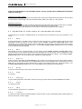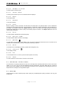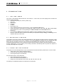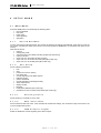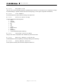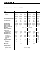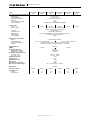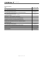
1
BTL-08 ECG
Series
USER'S MANUAL
v112z1IE24/04/2006EN
BTL-08 ECG Series
USER'S MANUAL
Before You Start
This manual has been written for the owners and operators of
the BTL-08 ECG products. It contains general instructions on
operation, precautionary practices and maintenance. While we
would like you to start using your equipment right away, we
encourage a thorough reading of this manual in order to fully
understand the operational features of your product.
All of us at BTL wish you every success with your BTL-08
system. We pride ourselves on being as responsive as possible
to our customer’s needs. Your suggestions and comments are
always welcome since we believe an ongoing relationship with
our customers is critically important to our future product line.
Please call us or email us your suggestions.
Please remember to complete the warranty registration form
printed in this manual. The warranty form should be returned to
us no later than 30 days following installation of your equipment
to initiate warranty protection.
Again, thanks for being a BTL customer. In the event of a
problem, or if you require service, please make an initial call to
your local distributor, who will decide whether to refer the
problem to our office.
page
2
of
30
BTL-08 ECG Series
USER'S MANUAL
CONTENTS:
1
GENERAL DESCRIPTION..................................................................................................................................5
2
INSTRUCTIONS FOR USE.................................................................................................................................6
2.1
Outward Appearance .....................................................................................................................................6
2.1.1
Rear View.................................................................................................................................................7
2.2
Assembly and Putting into Operation .............................................................................................................7
2.3
Overview of Functions of Keyboard Buttons ..................................................................................................8
2.3.1
auto ..........................................................................................................................................................8
2.3.2
man ..........................................................................................................................................................8
2.3.3
profile........................................................................................................................................................8
2.3.4
print ..........................................................................................................................................................8
2.3.5
stop...........................................................................................................................................................8
2.3.6
analyse .....................................................................................................................................................8
2.3.7
copy..........................................................................................................................................................8
2.3.8
1mV ..........................................................................................................................................................8
2.3.9
restart .......................................................................................................................................................8
2.3.10
number of leads........................................................................................................................................9
2.3.11
select leads ..............................................................................................................................................9
2.3.12
mm/s.........................................................................................................................................................9
2.3.13
mm/mV .....................................................................................................................................................9
2.3.14
filter...........................................................................................................................................................9
2.3.15
drift ...........................................................................................................................................................9
2.3.16
monitor leads ............................................................................................................................................9
2.3.17
patient.......................................................................................................................................................9
2.3.18
menu ........................................................................................................................................................9
2.3.19
contrast.....................................................................................................................................................9
2.3.20
esc............................................................................................................................................................9
2.3.21
enter .........................................................................................................................................................9
2.4
Checking Loose Leads...................................................................................................................................9
2.5
Printer ............................................................................................................................................................9
2.6
Accumulator .................................................................................................................................................10
2.7
Lithium Battery .............................................................................................................................................10
3
EXAMINATION..................................................................................................................................................11
3.1
"On-Line" Mode............................................................................................................................................11
3.2
Selecting A Profile........................................................................................................................................11
3.3
Fixing the Electrodes....................................................................................................................................11
3.3.1
Limb Electrodes......................................................................................................................................12
3.3.2
Chest Electrodes ....................................................................................................................................12
3.4
Examination Process ...................................................................................................................................12
3.4.1
Examination in the Automat Profile ........................................................................................................12
3.4.2
Examination in the Manual Profile ..........................................................................................................13
3.4.3
Examination in User Profiles ..................................................................................................................13
3.5
Reliability of Measuring and Diagnostics......................................................................................................13
3.6
Use of Filters ................................................................................................................................................13
4
SETUP MODE ...................................................................................................................................................17
4.1
Main Menu ...................................................................................................................................................17
4.1.1
Record Database ...................................................................................................................................17
4.1.2
Unit Setup...............................................................................................................................................17
4.1.2.1
Starting Profile ..................................................................................................................................17
4.1.2.2
Max. Heart Rate................................................................................................................................17
4.1.2.3
QRS Acoustic Signal ........................................................................................................................17
4.1.2.4
Rhythm lead......................................................................................................................................18
4.1.2.5
Line Width.........................................................................................................................................18
4.1.2.6
Patient Card Setup ...........................................................................................................................18
4.1.2.7
Optional Patient Data........................................................................................................................18
4.1.2.8
Battery Status Indication ...................................................................................................................18
4.1.2.9
Sleep Mode Interval ..........................................................................................................................18
4.1.2.10
Export setup - Export to BTL-08 / Modem.........................................................................................19
4.1.2.11
User Setup........................................................................................................................................20
4.1.2.11.1
Date / Time..................................................................................................................................20
4.1.2.11.2
Display Contrast..........................................................................................................................20
page
3
of
30
BTL-08 ECG Series
4.1.2.11.3
4.1.2.11.4
4.1.2.11.5
4.1.2.11.6
4.1.2.11.7
4.1.2.11.8
4.1.2.11.9
4.1.2.11.10
4.1.2.11.11
4.1.3
4.1.3.1
4.1.3.2
4.1.4
4.1.5
4.1.6
5
5.1
5.2
USER'S MANUAL
Select Language .........................................................................................................................20
Touch Panel Calibration ..............................................................................................................20
Repair of files ..............................................................................................................................20
File system formatting .................................................................................................................20
Default settings – no user data loss ............................................................................................20
Offline automat............................................................................................................................20
Color inversion into on-line..........................................................................................................20
Delete patient after print ..............................................................................................................20
Sound of keyboard ......................................................................................................................20
Profile Setup...........................................................................................................................................20
Setting Parameters of Profiles auto, man, normal ............................................................................21
Setting Parameters of Profiles long ..................................................................................................21
Select Physician .....................................................................................................................................21
Spirometry ..............................................................................................................................................21
Device Configuration Listing...................................................................................................................21
ACCESSORIES AND UPGRADES...................................................................................................................22
Accessories..................................................................................................................................................22
Upgrades .....................................................................................................................................................22
6
MAINTENANCE AND SAFETY ........................................................................................................................23
6.1
Cleaning of the equipment's surface and of its parts....................................................................................23
6.1.1
Cleaning of the Touch Screen ................................................................................................................23
6.1.2
Cleaning of accessories which come into contact with the patient (e.g. electrodes) ..............................24
6.2
Safety...........................................................................................................................................................25
6.3
Useful addresses .........................................................................................................................................26
6.4
Warranty ......................................................................................................................................................26
7
TECHNICAL PARAMETERS ............................................................................................................................27
page
4
of
30
BTL-08 ECG Series
1
GENERAL
USER'S MANUAL
DESCRIPTION
The BTL-08 series of electrocardiographs are advanced units with modern functional design. Developed in
accordance with the latest standards in cardio-diagnostics, they will provide you with years of reliable and trouble free
service.
The BTL-08 electrocardiographs are available in two lines:
The BTL-08 SD line presents 1, 3 and 6 channel ECG with graphic display and alphanumeric keyboard. These
electrocardiographs feature all the benefits of advanced ECG monitoring. They are small in size, yet powerful in
performance. Other advantages include accurate ECG monitoring, simple operation, portability, lightweight, and the
possibility of battery operation.
The BTL-08 MD/MT line features 3, 6 and 12 channel electrocardiographs with graphic display or touch screen. The
advanced design together with an extensive range of parameters will fit the needs of the most demanding users. The
alphanumeric keyboard, comprehensive ECG recording, broad range of filtering methods and storing of large number
of records are only some of the characteristics of these top performance electrocardiographs.
The BTL-08 cardiographs are fully versatile, with a number of optional upgrades, such as PC software, ergometry
system and spirometry.
With every BTL-08 unit, system can purchase a cart specially designed for BTL products. Its versatile design allows
you to conveniently store your BTL equipment. The cart includes a range of accessory trays, and specially designed
cable arm for lead wires. Four well-built and steady castors ensure easy movement of the unit in the office or in
hospital wards.
Please visit out corporate website at http://www.btlnet.com for the latest information on BTL products and services.
page
5
of
30
BTL-08 ECG Series
2
USER'S MANUAL
INSTRUCTIONS
2.1
FOR
USE
OUTWARD APPEARANCE
Model BTL-08 MT ECG:
1.
2.
3.
4.
5.
6.
7.
8.
9.
10.
11.
printer cover
locking lever for printer head (models MD3, MD, MT) / lever to open printer (models SD1, SD3, SD6)
display
control light indicating ON status and charging
automat profile control light
manual profile control light
profile profile control light
control light indicating printer operation and print errors
patient cable connector
keyboard to control printer
keyboard to set record parameters
page
6
of
30
BTL-08 ECG Series
USER'S MANUAL
Layout of controls on the other ECG models is similar, see following pictures:
BTL-08 SD ECG
2.1.1
BTL-08 MD ECG
Rear View
20
12.
13.
14.
15.
16.
17.
18.
19.
20.
2.2
mains switch – positions 0 / I
mains plug
PC port
mains fuse
manufacture and type label (on the bottom)
mains voltage switch
RESET button to restart the equipment if the unit does not react to any commands
grounding screw (on the bottom)
accessory port (models MD3, MD, MT)
ASSEMBLY AND PUTTING INTO OPERATION
Inspect the box for damage and report any damage to carrier and distributor. Do not proceed with installation and
assembly if box is damaged.
Unpack the equipment and place it on a stable horizontal surface suitable for the equipment's weight. Always position
the unit out of direct sunlight. Always position the unit away from direct heat sources such as radiator or room heater.
Cooling of the equipment is provided for by forced air circulation. Cooling vents are located at the bottom of the
equipment and around printer and must not be covered. Do not position the equipment on a soft surface which may
obstruct air flow to the bottom cooling vents. Do not put any heat-producing devices or objects containing water or
other liquid on the equipment. Do not place the equipment close to devices producing strong electromagnetic, electric
or magnetic field (diathermy, X-rays, etc.), as this could affect equipment electronics.
Retain the original packaging to ensure maximum protection of the device during transportation.
page
7
of
30
BTL-08 ECG Series
USER'S MANUAL
PLUG THE DEVICE DIRECTLY IN THE MAINS SOCKET. DO NOT USE ANY MULTI-CONNECTION EXTENSION
CABLE OR ADAPTER.
Checking correct mains voltage:
Before first connection of the equipment to the mains check if the mains voltage switch (17) located on the rear panel
is in the position corresponding to the local voltage standards, either in the "230V" or "115V" position.
Switching the device on:
Plug the power supply into the mains socket and switch the O/ I rocker switch (12) on the rear panel to the "I" position.
Press the on/off switch on the top panel. The ON status is indicated by the control light (4).
The mains switch (12) should always be in the "I" position so that the accumulators can be recharged.
2.3
OVERVIEW OF FUNCTIONS OF KEYBOARD BUTTONS
The following is an overview of available buttons on all models; some of the buttons may not be available on your
model.
2.3.1
auto
Press the print button in the auto mode to record and print ECG curve from 12 leads including analysis and verbal
interpretation (comes as option). For print options, use the number of leads and select leads buttons. Print
parameters can be modified during printing. Press the stop button to stop printing. The unit's internal memory stores
10-sec signals for later print, analysis and saving – use the copy, analyse, patient, menu buttons. The use of auto
mode is indicated by the pilot light (5).
2.3.2
man
Record ECG curve from 12 leads manually. For print options, use the number of leads and select leads buttons.
Print parameters can be modified during printing. Press the print button to start printing, press the stop button to stop
printing The unit's internal memory stores 10-sec signals for later print, analysis and saving – use the copy, analyse,
patient, menu buttons. The use of man mode is indicated by the pilot light (6).
2.3.3
profile
Select an active profile (edited in profile settings) to record ECG curve according to the user preset settings saved in
the unit's memory. Print parameters can be modified during printing. Press the print button to start printing, press the
stop button to stop printing The unit's internal memory stores 10-sec signals for later print, analysis and saving – use
the copy, analyse, patient, menu buttons. The use of profile mode is indicated by the pilot light (7).
2.3.4
print
To print record and saving into the memory in the selected profile.
2.3.5
stop
To stop print.
2.3.6
analyse
To print verbal interpretation and analysis of the last record (only active with the optional DIAGNOSTICS module).
2.3.7
copy
To reprint last record.
2.3.8
1mV
To print calibration signal of the 1mV amplitude.
2.3.9
restart
To restart ECG inputs and ECG internal amplifiers. Use this function in case of inadequate quality of ECG signals or if
the ECG curves are out of the display.
page
8
of
30
BTL-08 ECG Series
2.3.10
USER'S MANUAL
number of leads
To select number of leads for print.
2.3.11
select leads
To select groups of leads for print. The selected leads are displayed.
2.3.12
mm/s
To set paper speed.
2.3.13
mm/mV
To set print sensitivity.
2.3.14
filter
Button for setting of mains noise filter, muscular filters and artifact filter. The particular filters or their combinations
cyclically shift when pressing the button. The current filter or combination of filters is displayed in the top status bar on
the display. It is possible to select the adaptive auto filter which on the basis of the signal analysis automatically
activates the needed filter so that the quality of the resulting signal is maximum. The adaptive auto filter cannot be
combined with other filters.
2.3.15
drift
To switch between baseline filters (Anti Drift System).
2.3.16
monitor leads
To switch between leads monitored on the display.
2.3.17
patient
To enter data of a new patient. Press enter to save. The data is printed and saved with record. The data can be
recalled from the database (in the menu), viewed (MT model only) or printed.
2.3.18
menu
To activate menu on the display (unit setup, patient data management, etc.)
2.3.19
contrast
To set display contrast.
2.3.20
esc
To cancel selection and / or return to previous window (data is not saved).
2.3.21
enter
To confirm selection and save data or continue to next window.
2.4
CHECKING LOOSE LEADS
If an electrode is not properly attached to the skin, the control light of the selected profile starts to mark on the screen
LRFN, V1, V2, V3, V4, V5, V6. They are displayed inversely (models SD1, SD3, SD6, MD3, MD, MT). Check the
electrodes and press restart. Record the ECG signal only after the error messages stop. Recording the ECG curve
despite the error messages can bring distorted signal.
2.5
PRINTER
The printer prints on thermo-sensitive paper. Paper quality may considerably affect quality of printouts. Use only good
quality paper.
page
9
of
30
BTL-08 ECG Series
USER'S MANUAL
The yellow pilot light (8) indicates printer error status. Possible causes:
•
printer is out of paper
•
bad pressure of the head on the paper (in the MD3, MD and MT models: the printer head locking lever (2) is
in the position "unlocked"; shift the lever to the left to lock the head and make it ready for print).
In addition, the SD1, SD3, SD6, MD3, MD, MT models display: "Pressure!" and/or "Paper!".
Inserting paper (models SD1, SD3, SD6): Press the button (2) to open the printer cover (1). Insert the paper roll. The
thermo-sensitive layer should face the printer head. Close the cover. The control light indicating printer operation and
print errors (8) stops lighting.
Inserting paper (models MD3, MD, MT): Open the printer cover (1), shift the locking lever (2) to the right and insert the
paper roll. Put the end of the paper under the roller. The roller automatically starts to roll the paper on. Close the cover
and turn the locking lever back to the left.
2.6
ACCUMULATOR
See section Technical Parameters for details on the accumulator type. Have the accumulator replaced by authorized
service personnel only.
The accumulator is continuously recharged from the mains. The accumulator is recharged even when the unit is
switched off, provided it is connected to the mains and the mains switch (12) is in I position. It takes about 6 - 10 hours
to fully recharge the accumulator (recommended overnight). If the accumulator is not charged the recorded ECG
curve will likely be not printed. Save the record and print it after at least a partial accumulator recharge (about one
hour).
An audio tone (short intermittent beeping - can be switched off) signals discharged accumulator. On models with
displays, the "battery" warning message appears on the screen.
The status and operation of the equipment is also indicated by the pilot light (4).
•
•
•
•
equipment is on, accumulator is charged:.........................................................pilot light illuminate yellow
equipment is on, operating from accumulator: ..................................................pilot light illuminate green
equipment is off, accumulator is charged: ........................................................pilot light illuminate yellow
equipment is off, accumulator fully charged: ....................................................pilot light is off
If the discharge status is signalled it is likely that the full ECG record will not be printed. However, the data is still
saved in the memory.
It is recommended that the accumulator is kept permanently charged. Whenever possible, plug the ECG to the mains
and switch the mains switch (12) to the I position.
2.7
LITHIUM BATTERY
See section Technical Parameters for details on battery type. Have the battery replaced by authorized service
personnel only.
page
10
of
30
BTL-08 ECG Series
3
3.1
USER'S MANUAL
EXAMINATION
"ON-LINE" MODE
This mode is automatically selected after the unit's switch-on. In this mode, the screen displays the recorded ECG
signal and other information:
•
selected print profile (auto, manual, profile, long)
•
heart rate
•
paper speed
•
sensitivity
•
set filters
•
loose leads, if any
•
name of displayed lead (only when changed – press the monitor leads button)
•
number and names of the leads to be printed (MT model); The SD1, SD3, SD6, MD, MD3 models display
this information only when it is set (pressing the number of leads and/or select leads buttons).
•
ECG curve
•
error messages: battery (discharged battery), paper (no paper), pressure (printer head unlocked)
•
when the 10-second record is saved into the memory the equipment displays saving (or measuring in some
software versions) on the screen
3.2
SELECTING A PROFILE
The 'profiles' are pre-set recording and printing parameters for easy and fast recording and print. Their factory preset
parameters can be changed in the menu. In addition to the profiles automat ( the auto button) and manual (the man
button) the user can define a number of other profiles (press the profile button repeatedly to see all profiles).
The preset profile parameters can be changed at any time before and during recording. Press the respective buttons.
Press the print button to start recording. The recording terminates automatically after the preset time elapses or
manually if the stop button is pressed.
3.3
FIXING THE ELECTRODES
The quality of record is also dependant on the contact between the electrode and the patient's skin. For best contact:
•
make sure the skin is warm and patient relaxed
•
rub the skin with alcohol before fixing the electrodes
•
use enough ECG gel on the electrode
Recommended order to fix the electrodes:
•
first fix the N electrode to the right leg
•
then fix the other limb electrodes R, L, F
•
finally fix the chest electrodes in this order: V4 – V2 – V1 – V3 – V6 – V5
The following is a detailed description of the placement of electrodes.
page
11
of
30
BTL-08 ECG Series
3.3.1
USER'S MANUAL
Limb Electrodes
R – red
L – yellow
F – green
N – black
3.3.2
Chest Electrodes
V1 – red
V2 – yellow
V3 – green
V4 – brown
V5 – black
V6 – violet
3.4
- right arm
- left arm
- left leg
- right leg
- 4th intercostal
to the right of sternum
- 4th intercostal space
to the left of sternum
- between V2 and V4
- 5th intercostal in MDCL line
- at height of V4 in the front axillary line, evenly between V4 and V6
- at height of V4 in the middle axillary line
EXAMINATION PROCESS
•
Switch the unit on by the on/off button:
•
Enter the name of the patient to be printed in the record (if desired) :
(optional)
•
Select print profile – e.g. auto:
•
Fix the electrodes. Make sure that all leads are correctly connected and that ECG does not report any loose
leads. Check the signal on the display.
•
Press print:
3.4.1
Examination in the Automat Profile
SWITCH ON the unit – FIX ELECTRODES – SELECT PROFILE by auto button (unit setup) – START RECORDING
by print button – AUTOMATIC TERMINATION
Before recording, you can change the following parameters:
•
•
•
•
printed ECG leads, format of leads (1x12, 2x6, 3x4...)
paper speed
sensitivity
active filters (muscular, ADS and mains filter)
The examination will stop automatically after the preset time; or press the stop button to terminate the examination at
any time.
If the diagnosis and analysis has not been preset for print, you can still print it - press analyse (only with
DIAGNOSTICS module).
To reprint the record, set the print options using the keyboard and press copy.
For automatic recording of another patient, press print.
page
12
of
30
BTL-08 ECG Series
3.4.2
USER'S MANUAL
Examination in the Manual Profile
SWITCH ON the unit – FIX ELECTRODES – SELECT PROFILE by man button (unit setup) – START RECORDING
by print button – STOP recording by stop button
Before recording, set the following parameters (or change them during recording):
•
•
•
•
•
paper speed - mm/s button
sensitivity - mm/mV button
number of leads - number of leads button
leads to be printed - select leads button
filters - filter and drift buttons
Press print to start.
Press stop to stop recording. The last 10-sec strip has been saved in the memory.
Press analyse to print interpretation and analysis (only with DIAGNOSTICS module).
To reprint the last 10 sec record, set the print options and press copy.
For automatic recording of another patient, press print.
3.4.3
Examination in User Profiles
SWITCH ON the unit – FIX ELECTRODES – SELECT PROFILE by profile button (unit setup) – START RECORDING by
print button – AUTOMATIC TERMINATION or INTERRUPTION by stop button
Other steps are similar to those described in section 3.4.1.
3.5
RELIABILITY OF MEASURING AND DIAGNOSTICS
The parameters analysed on the basis of an averaged heart cycle can only be considered correct if the record has not
been too much distorted by the mains noise, by artefacts of myopotentials or by other noises, and provided the key
points of the P-QRS-T complex have been properly identified by the unit. The parameters' accuracy can be also
affected by inclusion of aberrant cycles to the averaged cycle, in case the unit incorrectly classifies them as typical for
the record. The unit attempts to determine the parameters of every record automatically. Therefore you should ensure
that at least three cycles typical for the record are correctly averaged and that the number of aberrant cycles does not
exceed the number of non-aberrant cycles.
3.6
USE OF FILTERS
Fully automatic adaptive filter (adaptive auto) – a filter which performs permanent analysis of the recorded signal
and on the basis of the acquired data filters the signal so as to achieve the optimum result. This filter comprises all
other filters automatically, therefore it CANNOT be combined with other filters.
ADAPTIVE-AUTO FUNCTIONALITY DESCRIPTION - the basic idea of muscle tremor filtering is based on low-pass
filter with optional cutoff frequency can lead to unsatisfactory result in ECG parts with low signal frequencies and also
to distortion of amplitudes in parts with high frequency content e.g. QRS complex. The adaptive filter as a new
technique process ECG signal the same way as simple lowpass filter with respect to signal frequency content. This
approach gives more effective results in noise filtering and in preservation of signal amplitudes, especially in QRS
complexes.
The raw signal of ECG (fig 1) is analyzed by rough curvature analyzing process resistant to powerline and muscular
noise which control function is derived from (fig.2). The control function enters to decision and executive block
consisting of four short FIR filters with different cutoff frequencies where all of the filters are executed but outputs of
them are weighted by fuzzy rules and reconstructed to clean ECG signal according to control function, i.e. parts of P
wave or T wave are reconstructed with respect of their content of frequencies around 0 – 15 Hz, and in parts of QRS
complex frequencies of 0 – 100 Hz are kept for good spike and slope representation. (fig 3)
page
13
of
30
BTL-08 ECG Series
USER'S MANUAL
Figure 1
The original raw signal of ECG
Figure 2
The control function as mentioned above in text
page
14
of
30
BTL-08 ECG Series
USER'S MANUAL
Figure 3
Output signal with Cut off frequencies
The adaptive filter is as complex filtering method enhanced by cubic spline baseline wander filtering. The baseline
points are extracted from original signal by ECG segment analysis and interpolated by piecewise cubic splines
method to remove baseline wandering with respect to low frequency content of ECG signals e.g. ST segments and
the other “slow” parts. The brief explanation is on figure 4.
Figure 4
Original ECG signal with baseline wandering and his spline baseline removal
Adaptable mains filter 50 Hz-60 Hz – designed to reduce noise from the mains. Adaptable to the changes in the
noise frequency. Typical for this noise is a harmonic (sinusoid) course with a period of approx. 1mm at the record
speed of 50mm/sec. Does not affect any diagnostically important record parameters.
page
15
of
30
BTL-08 ECG Series
USER'S MANUAL
Muscle tremor filter 35 Hz – filter with 35 Hz cut-off frequency. Designed to remove muscular artefacts.
Characterised by non-harmonic course with short random period. Using this filter can also partly remove disturbances
from the mains.. It is therefore useful to choose its combination with the mains filter – setting “35.50Hz”.
Muscle tremor filter 25 Hz – filter with 25 Hz cut-off frequency. Designed to remove muscular artefacts and possible
electromagnetic disturbance from other electric appliances. Characterised by non-harmonic course with short random
period. Using this filter can also partly remove disturbances from the mains. It is therefore useful to combine it with the
mains filter – setting 25.50Hz. In certain cases this filter can influence some values of amplitudes of the QRS complex.
Anti Drift System – base-line filters – filters to remove base-line drift. Use these filters in cases when the base-line
drift in the recorded examination is significant. Follow this scheme:
First use the filter with the longest time constant – ADS 3.2 sec. If the base-line drift is significant and the ECG record
'escapes' from the screen, switch the ADS filter successively to the filters with faster reaction - shorter time constant
(that is from ADS 3.2 sec towards 0.1 sec). The value ‘heart rate x time of reaction of the filter‘ should considerably
exceed 10 to avoid undesirable influence on the record. The use of filters with fast reaction (small number in the filter's
name – 0.1 sec) can possibly result in some distortion of the P-QRS-T intervals (in particular of the diagnostically
important S-T interval).
Good results are achieved with the setting of ADS 1.5sec – we recommend using of this particular filter. In case of
complicated conditions during the recording of the ECG signal (strong electromagnetic disturbance, scanning of ECG
without using of high-conductivity gel, and the like) we recommend using the ADS filter 0.6sec.
Splines filter
A new generation filter which is able to suppress the base-line fluctuation almost perfectly, while all important
parameters of the ECG signal remain preserved. It is based on the parameters of the record and on the precisely
specified points in the record, which enables it to eliminate considerable interference of this type.
All filters can be combined for optimum filtration.
page
16
of
30
BTL-08 ECG Series
4
4.1
SETUP
USER'S MANUAL
MODE
MAIN MENU
Press the menu button to scroll through the following items:
•
Record database
•
Unit setup
•
Profile setup
•
Select physician
•
Spirometry
4.1.1
Record Database
To open, view and print the last records. The records are stored in the memory automatically. If the memory is full, the
new record overwrites the oldest record stored. The records marked as archive are not overwritten and remain in the
memory.
Work with the record:
•
reprint it
•
change print profile
•
view the record on the display including analysis (MT model only)
•
mark it as archive
•
export it to a PC (to the BTL-08 Win program)
•
export it to a PC via modem and dial-up line (MT model only)
•
export it to a PC via mobile phone (MT model only)
4.1.2
Unit Setup
Set the following parameters:
•
time
•
date
•
profile to be used on opening
•
max. heart rate
•
acoustic signalling of the QRS complex
•
thickness of print
•
patient card details
•
acoustic signalling of discharged battery
•
sleep mode interval
•
display contrast
•
language
•
touch-panel calibration (MT model only)
•
parameters for PC or modem transmission (MT model only)
4.1.2.1
Starting Profile
Set the profile you would like to use on start.
4.1.2.2
Max. Heart Rate
Set the maximum heart rate value. If the recorded HR exceeds the settings, the unit starts to beep. Set the max. HR
to zero to disable this function.
4.1.2.3
QRS Acoustic Signal
Enable or disable the acoustic signalling of the QRS complex.
page
17
of
30
BTL-08 ECG Series
4.1.2.4
USER'S MANUAL
Rhythm lead
Here you can set from which lead the device will determine the heart rate. In most cases it is not necessary to change
the default settings, in special cases the lead can be changed (e.g. in some types of ergometric examination).
4.1.2.5
Line Width
Set desired thickness of print. Refine according to the paper used.
4.1.2.6
Patient Card Setup
Activate / deactivate the following items:
•
name
•
surname
•
third name
•
ID
•
age
•
sex
•
weight
•
blood pressure
•
height
•
pacemaker
•
3 user-defined items (MT model only)
4.1.2.7
Optional Patient Data
Add your own items on the patient card. Available only with the MT model.
4.1.2.8
Battery Status Indication
Enable/disable the acoustic signalling of discharged battery (short fast beep).
4.1.2.9
Sleep Mode Interval
Set the period of inactivity after which the equipment switches off.
page
18
of
30
BTL-08 ECG Series
4.1.2.10
USER'S MANUAL
Export setup - Export to BTL-08 / Modem
Available only with the MT model.
Select direct data export to PC – via the serial line RS232 – option connection = serial line.
Or select data transfer via modem (by phone, mobile phone...) – option connection = modem. Set the control
commands for your modem and your phone network. Typical setting for standard modem:
•
transmission speed: according to the modem's type, typically 19 200 for mobile phone, 115 200 for
modem
•
init string: ATX3Q0V1E1S0=0
•
dial string: ATDTdialled_phone_number (i.e., for example: ATDT2724856326)
•
your identification
The receiving party must have a PC with modem and running program BTL-08 ECG Modem. View and process the
received data using the BTL-08 Win program.
Schematic connection of ECG MT at the data export to a PC via modem and dial-up line
Schematic connection of ECG MT at the data export to a PC via mobile phone
page
19
of
30
BTL-08 ECG Series
4.1.2.11
USER'S MANUAL
User Setup
4.1.2.11.1
Date / Time
Setting of the date and time to be printed in the reports.
4.1.2.11.2
Display Contrast
Setting of the display contrast.
4.1.2.11.3
Select Language
Setting of the language in which the equipment communicates. The change of language does not occur before restart
of the equipment.
4.1.2.11.4
Touch Panel Calibration
Available only with the MT model.
If the buttons on the touch screen do not react when pressed, the touch screen needs calibration.
Calibration values are displayed on the screen. Use the soft touch stylus to make adjustments to the
sensitivity of the buttons.
Press esc to stop calibration. To verify touch screen adjustments, use the 'touch panel function
test' function.
4.1.2.11.5
Repair of files
If the stored data are corrupt because of interference or a device fault, there may appear errors in the file system (loss
of some records, loss of some of the stored patients). This function starts diagnostics of the file system and tries to
repair the fault without loss of the stored data, if possible. Depending on the amount of the stored data, this function
can take a very long time (hours), therefore we recommend running this function e.g. overnight. If this function is run,
it is necessary to wait until it is complete or to reset the device.
4.1.2.11.6
File system formatting
This function initializes the entire file system, i.e. it deletes all data stored in device and puts the device into the
initialized state (i.e. the same state as at purchase of the device). This function should be used only in case of a
serious breakdown or if the user wants to initialize the device completely.
4.1.2.11.7
Default settings – no user data loss
This function puts the device into the same state as at purchase (setting of language, colours, etc.) and at the same
time it keeps all stored data of profiles, patients, physicians and records.
4.1.2.11.8
Offline automat
At switching on this function, the data in the "automat" mode are loaded into the device's memory, then processed and
then printed. Thanks to it it is possible to process these data better, to apply the adaptive auto automatic filter, or to
replace the standard ADS filter with the Splines filter.
4.1.2.11.9
Color inversion into on-line
Setting of normal (white on black) or inverse (black on white) wiev of on-line screen..
4.1.2.11.10
Delete patient after print
Enables to cancel displaying of the patient data after taking of one record. At the following recording the patient data
will not be displayed anymore in the record.
4.1.2.11.11
Sound of keyboard
Enable/disable the acoustic signalling at the push of a key.
4.1.3
Profile Setup
Set the parameters of all print profiles: the default profiles automat and manual, other standard profiles (marked
profile) and profiles for long recording (long profiles).
page
20
of
30
BTL-08 ECG Series
4.1.3.1
USER'S MANUAL
Setting Parameters of Profiles auto, man, normal
Set these parameters for each profile:
•
profile name
•
active - yes / no (will be displayed in the list of profiles)
•
sensitivity
•
paper speed
•
length of printed and saved record
•
print the record?
•
printer mode (stops automatically after preset time or must be stopped manually by the stop button)
•
print options:
o number of leads printed above each other
o length of printing
o print mode: synchronous / in-time (the printed curves are either all recorded at the same time or
recorded at the time of printing)
o data to be printed in the header of the record
o print leads averaging yes / no (only with DIAGNOSTICS module)
o print 10 sec rhythm (only with DIAGNOSTICS module)
o print analysis (only with DIAGNOSTICS module)
o print verbal interpretation (only with DIAGNOSTICS module)
4.1.3.2
Setting Parameters of Profiles long
Set the following parameters:
•
profile name
•
active - yes / no (will be displayed in the list of profiles)
•
sensitivity
•
paper speed
•
length of saved record
•
data to be printed in the header of the record
•
numbers of printed and recorded leads
4.1.4
Select Physician
Set the physician's name and facility as it will appear on the record.
4.1.5
Spirometry
Attach the spirometry module to the patient connector (9) on the side of the unit (instead of the patient cable).
For correct evaluation, enter patient's age, height and sex.
4.1.6
Device Configuration Listing
If the restart button is held pressed when switching the device on by the on/off button, the printer pritns out the
current configuration of the device, i.e. the ecg type, diagnostics version, serial number, versions of mainboard,
analog and power supply, firmware version and set language. Then there is printed setting of all three profiles: auto,
manual and profile.
page
21
of
30
BTL-08 ECG Series
5
USER'S MANUAL
ACCESSORIES
5.1
AND
UPGRADES
ACCESSORIES
The equipment is not designed for use with other medical devices except for those stated in this manual.
The following is a list of accessories that can be supplied with the equipment, both standard and optional.
BTL accessories:
•
mains cable
•
limb electrodes
•
chest electrodes
•
self-adhesive electrodes
•
thermo-sensitive paper
•
touch-pen (MT type only)
•
spare fuse
•
BTL patient cable, type C008.108
•
BTL patient cable for self-adhesive electrodes, type C008.109
•
user's manual
•
suction cup electrodes set
•
spirometry module BTL-08 Spiro
•
software BTL-08 Win
•
software BTL-08 Win Ergo
•
software BTL-08 ECG Modem
5.2
UPGRADES
Equip your ECG with the DIAGNOSTICS module for full interpretation and analysis. The package includes:
•
•
•
•
•
table of analysis results (time intervals, amplitudes of segments, electrical axes calculation and pulse
frequency)
verbal interpretation
leads averaging (average complexes with optional reference marking)
overview of the last 10 sec of heart rate
pacemaker performance analysis (measurement of pulses and reference marking)
page
22
of
30
BTL-08 ECG Series
6
USER'S MANUAL
MAINTENANCE
AND
SAFETY
All maintenance and repairs must be carried out by authorized personnel only. The manufacturer bears no
responsibility for the results of maintenance or repairs by unauthorized persons.
Safe operation of any item of medical equipment requires close attention to detail. Please check the following on a
regular basis:
Power cord and plug - check for frays and kinks. Ensure that the insulation is not damaged in any way.
Wires, cables and electrodes - check for frays, cuts or tears in the insulation. Always route electrical cords and cables
away from user or patient foot traffic areas where they could increase the chance of a tripping related accident.
Check the unit before each use to determine that all controls function normally.
No part of the equipment needs to be aseptic or sterilized.
Fuse replacement
The fuse is located in the round black box (15) on the rear panel. Make sure the mains switch (12) is in the "0“
position. Unplug the power supply from the mains and from the equipment. Turn the segment of the fuse case to the
left by a fitting screwdriver or coin in the slot. Remove the fuse. Insert a new fuse of the same rating and turn the box
to the right.
Switching mains voltage
Before first connection of the equipment to the mains it is necessary to check if the mains voltage switch (17) is in the
position corresponding to the correct voltage configuration, either in the "230V" or "115V" position. To change the
voltage, make sure that the mains switch (12) is in the 0 position. Unplug the power supply from the mains as well as
the equipment. Turn the segment of the switch by a fitting screwdriver or coin in the slot in the desired direction.
Transport and Storage
We recommend keeping the original packaging of this equipment to ensure its maximum protection during
transportation. Unplug the mains cable and the accessories cables. The equipment must be stored or transported as
defined in section Error! Reference source not found. Error! Reference source not found..
The equipment is designed for use with defibrillator. The defibrillator must comply with the IEC 601-2-4 and IEC 6012-25 standards. The equipment is defibrillation resistant only if the original BTL cable is used.
The examination couch for ECG recording should be placed as far as possible from any potential sources of noise
(mains cables in walls, electrical appliances) to reach the best quality of ECG signal. The conductive parts of the
electrodes must not touch other conductive parts of the couch or the ground.
6.1
CLEANING OF THE EQUIPMENT'S SURFACE AND OF ITS PARTS
To keep the device clean, do not store or use it in dusty environment and do not spill any liquid on the surface. To
clean, turn the equipment off and unplug the power supply. Clean the unit with a damp cloth. Do not use abrasive
materials. Do not use agents containing alcohol, ammonia, benzine, thinners. We recommend that you clean the
accessories that come into contact with the patient after each treatment. Use appropriate agents.
6.1.1
Cleaning of the Touch Screen
The surface of the touch screen can be cleaned using agents designed for cleaning of monitor screens or for cleaning
of glass surfaces. The agents may be applied only by means of a spray. Sprinkle the centre of the touch screen
SLIGHTLY with the cleaning agent and then wipe and polish the surface using a dry cloth. Press the cloth VERY
LIGHTLY, otherwise the touch screen could crack.
ATTENTION
The cleaning agent must not get under the edges of the touch screen, otherwise it could penetrate into the equipment.
The cleaning agent should not get into contact with any other part of the equipment than the touch screen.
page
23
of
30
BTL-08 ECG Series
6.1.2
USER'S MANUAL
Cleaning of accessories which
the patient (e.g. electrodes)
come
into
contact
with
We recommend cleaning these parts after treating of each patient. For cleaning use agents which were approved by
the competent health officer (e.g. Sekusept, Bacilol, Incidur spray for the accessory cables, and the like).
page
24
of
30
BTL-08 ECG Series
6.2
USER'S MANUAL
SAFETY
ATTENTION!
Only the original BTL patient cable can be connected to the connector marked with this label to insure the defibrillation
protection. The applied part is of the CF type.
The grounding screw marked with this label is connected to the equipment's frame. In case of interference, ground the
unit using this screw: connect it for example to the metal frame of the couch.
ATTENTION!
This system has no user serviceable parts or assemblies. Do not remove the instrument covers under any
circumstances. Call your distributor for advice about any malfunction.
The device is equipped with a protection system that prevents connection of other accessories than supplied
from the manufacturer.
Safety Precautions
•
•
•
•
•
•
•
•
•
•
•
•
•
•
•
•
•
•
•
•
Read this manual thoroughly before operating the equipment.
All staff should be instructed by the manufacturer or the distributor in the operation, maintenance and checking of
the equipment and of all safety features and protocols.
Make sure the electrical network in your facility is in compliance with valid norms.
Check if the voltage switch located at the bottom of the equipment is switched to the correct voltage for your
facility.
Do not use this equipment in the presence of explosive gases and flammable anesthetics.
Using this equipment in close proximity to other equipment may cause electromagnetic interference.
Avoid the use of liquids in the immediate vicinity of this equipment since any liquid spilled onto the cabinet may
cause serious damage to internal components.
Inspect the equipment thoroughly before each use (loose cables, broken insulation of cables, display functions,
pilot lights, controls, etc.).
If the equipment shows any deviations from a normal operating situations, discontinue use and report the fault to
authorized service personnel.
Do not dismantle the equipment under any circumstances. Removal of protective covers implies the danger of
electrical injury. Replacement of the lithium battery and the lead accumulator may only be done by authorized
service personnel.
Make sure that all materials and parts that come to direct contact with patient's skin comply with your national
health standards.
The connectors for accessories as well as the other connectors must not be used for connection of anything else
than they are designed for, otherwise there is a danger of electric shock injury and serious damage to the
equipment!
Make sure that, during recording, the conductive parts of electrodes, including the N electrode, and all other
conductive patient applied parts do not touch ground or other conductive places in the office.
The equipment does not use or produce any toxic substances during its operation, storage or transport.
Exercise care when bringing the equipment from a cold environment to warm room. Do not plug it in the mains for
at least 1 hour. Never expose this equipment to very warm or very cold climatic conditions.
The time interval between switching the mains switch off and on must be at least 3 seconds.
This equipment does not imply any danger for patients with pacemakers.
The equipment is defibrillator resistant. Recording resumes till 10 seconds. Only the original BTL cable must be
used.
Do not touch the equipment during the defibrillation discharge.
Discard the equipment only after the lithium battery and lead accumulator was removed. The equipment does not
contain any toxic materials that would harm the environment and it can be done in a way which is usual for this
type of devices. The batteries must be disposed of in a proper way – not within the municipal waste.
Warning: removal of batteries causes irreversible damage of unit. Make only on environmental liquidation of unit!
Procedure: - Screw off the bottom cover of unit
- Remove the batteries with suitable tool (placing of batteries - see the picture)
page
25
of
30
BTL-08 ECG Series
•
•
•
•
•
•
•
USER'S MANUAL
This device is not designed for online ECG monitoring during the work with high-frequency surgical devices. It
must not be connected to the patient while a high-frequency surgical device is connected to the patient.
There is a potential risk resulting from simultaneous connection of several devices to single patient. Therefore,
we do not recommend the use of the equipment in connection with other devices, other then those described in
this manual.
Use the equipment and the accessories only in accordance with the manual.
Use recommended protective means when operating the equipment.
Keep the equipment out of the reach of children.
Always have the unit repaired by authorized service personnel.
Always follow your local and national electrical, safety and healthy standards when using this equipment. Call
your distributor for advice.
6.3
USEFUL ADDRESSES
The product is manufactured in accordance with the EU Medical Devices Directive by:
BTL Industries Ltd.
161 Cleveland Way
Stevenage
Hertfordshire, SG1 6BU United Kingdom
E-mail: [email protected]
http://www.btlnet.com
For service, please contact service department at [email protected].
6.4
WARRANTY
The Manufacturer of this product warrants the product to be free from defects in workmanship and material for a
period of twelve months after the date of shipment from the factory. This warranty excludes any disposable items and
accessories, including, but not limited to cables or leads, power cords and electrodes. The manufacturer agrees to
correct such defects without charge, or at its option to replace the item with a comparable model. To register and be
eligible for warranty service, you must send or fax the fully completed warranty registration form within 30 days of
installation. All costs of shipment are the responsibility of the purchaser. Damage to any part such as by accident or
misuse or improper installation or by use of any accessories or abrasive material not produced by the Manufacturer is
not covered by this warranty. Because of varying climatic conditions, this warranty does not cover any changes in
finish, including rusting, pitting, corrosion, tarnishing or peeling. Servicing performed by unauthorized persons render
this warranty invalid. There is no other express warranty. The Manufacturer hereby disclaims any and all warranties,
including but not limited to, those of merchantability and fitness for a particular purpose to the extent permitted by law.
The duration of any implied warranty which cannot be disclaimed is limited to the time period as specified in the
express warranty. The Manufacturer shall not be liable for incidental, consequential, or special damages arising out of,
or in connection with product use or performance except as may be otherwise accorded by law.
This warranty may differ from the warranty terms and conditions provided by your supplier and by applicable laws in
your country.
page
26
of
30
BTL-08 ECG Series
USER'S MANUAL
7
PARAMETERS
TECHNICAL
BTL-08 SD1
ECG
BTL-08 SD3
ECG
BTL-08 SD6
ECG
BTL-08 MD3
ECG
BTL-08 MD
ECG
BTL-08 MT
ECG
graphic
70 x 36
128 x 64
graphic
70 x 36
128 x 64
graphic
70 x 36
128 x 64
graphic
70 x 36
128 x 64
graphic
70 x 36
128 x 64
touch screen
118 x 90
320 x 240
functions
characters
functions
characters
functions
characters
functions
characters
functions
characters
functions
characters
touch-panel
Indication of discharged battery:
acoustic,
display
acoustic,
display
acoustic,
display
acoustic,
display
acoustic,
display
acoustic,
display
Check of loose leads:
yes,
individual
leads
yes,
individual
leads
yes,
individual
leads
yes,
individual
leads
yes,
individual
leads
yes,
individual
leads
58
58
112
112
5;10;25;50
5;10;25;50
5;10;25;50
5;10;25;50
2.5;5;10;20
2.5;5;10;20
2.5;5;10;20
2.5;5;10;20
12
12
12
12
3
6
3
6
1
1
1
1
I, II, III, aVR, aVL, aVF, V1, V2, V3, V4, V5, V6
R, L, F, N, C1, C2, C3, C4, C5, C6
112
5;10;25;50
2.5;5;10;20
12
12
3
Type:
Display:
dimensions (mm):
resolution:
Keyboard:
Paper width (mm):
Paper speed (mm/s):
Sensitivity (mm/mV):
Number of leads:
Number of channels:
Number of displayed leads:
Measured leads:
Electrode set:
Number of printed leads:
auto mode:
manual mode:
long mode:
Length of record:
auto mode (seconds):
long mode (minutes):
Record in auto mode:
58
5;10;25;50
2.5;5;10;20
12
1
1
1
1
1
1, 2, 3
1, 3
1
1, 2, 3, 6
1, 2, 3, 6
1
3
3
1
3, 4, 6
3, 4, 6, 12
1
3, 4, 6
3, 4, 6, 12
2
Saved 10-sec. records:
1;2;3;4;5;8;10;20
1.5;3;6;9
1.5;3;6;9
synchro
synchro
in-time
in-time
6
6
1;2;3;4;5;8;10;20
1.5;3;6;9
1.5;3;6;9
synchro
synchro
in-time
in-time
6
-
1;2;3;4;5;8;10;20
1.5;3;6;9
6
synchro
synchro
in-time
15
70
Filters:
mains filter (Hz):
muscular filters (Hz):
base-line filters (s)
adaptive auto
splines
50 / 60
50 / 60
25;35
25;35
3.2; 1.5; 0.6; 0.3; 0.1
-
50 / 60
50 / 60
25;35
25;35
3.2; 1.5; 0.6; 0.3; 0.1
-
50 / 60
50 / 60
25;35
25;35
3.2; 1.5; 0.6; 0.3; 0.1
yes
yes
yes
optional
yes
optional
yes
optional
yes
optional
yes
optional
yes
optional
3
3
3
3
3
3
1
-
5
5
10
10
Detection of pacemaker:
Diagnostics:
User profiles:
of normal type:
of long type:
Weight (max.):
Dimensions (l x w x h) [mm]:
2.1 kg
276 x 168 x 74
3.2 kg
330 x 270 x 74
Operating conditions:
temperature:
relative humidity:
atmospheric pressure:
position:
operation:
+ 10 °C to + 40 °C
30 % to 75 %
700 hPa to 1060 hPa
horizontal – on legs
continuous
page
27
of
30
BTL-08 ECG Series
USER'S MANUAL
Type:
BTL-08 SD1
ECG
BTL-08 SD3
ECG
Transport and storage conditions:
temperature:
relative humidity:
atmospheric pressure:
position:
max. duration of storage:
other conditions:
Power supply:
input:
mains voltage:
BTL-08 SD6
ECG
BTL-08 MD
ECG
BTL-08 MT
ECG
- 10 °C to + 55 °C
25 % to 85 %
650 hPa to 1100 hPa
any
1 year
transport only in the supplied packaging
30 VA
30 VA
30 VA
40 VA
40 VA
~ 99 V to 126 V (115 V nominal), AC
~ 198 V to 252 V (230 V nominal), AC
50 Hz to 60 Hz
II (according to IEC 536)
T1A / 250V, tube fuse 5 x 20 mm, according to IEC 127-2
on the rear panel, positions 0 / I
IP20
frequency:
protection class:
external fuse:
mains switch:
covering grade:
Internal chemical sources:
battery:
lead accumulator:
accumulator capacity:
charger:
40 VA
lithium battery CR2032
1x 6 V / 1.2 Ah; 25x97x52
1x 12 V / 1.2 Ah, 48x97x52
2 hours of ordinary use , approx. 15 min. of printing
internal, time for 100 % charging approx. 6 – 10 hours
Input impedance:
CMRR:
Sampling frequency:
long mode, one lead
long mode, two leads
Frequency range (filters off):
for +10% / -30 %
for +10% / -10 %
Amplitude accuracy:
Time accuracy:
Quantization noise:
Input noise:
A/D converter resolution:
Max. range of input voltage:
> 20 MΩ
> 95 dB
> 98 dB
2 000 Hz
18 000 Hz
9 000 Hz
0.05 Hz – 150 Hz
0.67 Hz – 40 Hz
±2%
±2%
3.9 µV
< 8 µV
13 bit
AC: ± 15.9 mV; DC: ± 400 mV
Applied part:
Connection to PC:
Connection to:
modem:
mobile phone:
BTL-08 MD3
ECG
CF type
RS232
RS232
RS232
RS232
RS232
RS232
no
no
no
no
no
no
no
no
no
no
yes
yes
page
28
of
30
BTL-08 ECG Series
USER'S MANUAL
Applicable Standards:
Name
IEC, EN, ISO, MDD
Medical electrical equipment
IEC 601-1
Part 1: General requirements for safety
Amendments to IEC 601-1
A2, A11, A12
Medical electrical equipment
Part 1: General requirements for safety
IEC 60601-1-1
1.Collateral standard: Safety requirements for medical electrical systems
Medical electrical equipment
Part 1: General requirements for safety
IEC 601-1-2
2. Collateral Standard: Electromagnetic compatibility.
Requirements and tests
Industrial, scientific and medical (ISM) radio-frequency equipment - Radio disturbance
EN 55011
characteristics - Limits and methods of measurement
Electromagnetic compatibility (EMC) - Part 4: Testing and measurement techniques - Section
IEC 61000-4-2
2: Electrostatic discharge immunity test - Basic EMC Publication
Electromagnetic compatibility (EMC) - Part 4: Testing and measurement techniques - Section
IEC 61000-4-3
3: Radiated, radio frequency, electromagnetic field immunity test
Electromagnetic compatibility (EMC) - Part 4: Testing and measurement techniques - Section
IEC 61000-4-4
4: Electrical fast transients/burst immunity test - Basic EMC Publication
Electromagnetic compatibility (EMC) - Part 4: Testing and measurement techniques - Section
IEC 61000-4-5
5: Surge immunity test
Medical electrical equipment
Part 1: General requirements for safety
IEC 601-1-4
4.Collateral standard: Programmable electrical medical systems
Medical devices - Risk analysis
EN 1441, ISO 14791
Biological evaluation of medical devices - Part 1: Evaluation and testing
ISO 10 993-1
The Medical Devices Directive 93/42/EEC
MDD 93/42/EEC
Medical electrical equipment - Part 2: Particular requirements for safety of
electrocardiographs
Amendment to IEC 601-2-25
page
29
of
30
IEC 601-2-25
A1
BTL-08 ECG Series
USER'S MANUAL
This product is manufactured in accordance with the EU Medical Devices Directive by:
BTL Industries Ltd.
161 Cleveland Way
Stevenage
Hertfordshire
SG1 6BU
United Kingdom
E-mail: [email protected]
http://www.btlnet.com
For service, please contact service department at [email protected].
© All rights reserved. No part of this manual may be reproduced, saved in a research centre or transferred by any means incl.
electronic, mechanic, photographic or other records without previous approval from BTL Industries Limited
BTL Industries Limited operates a policy of continuous development. Therefore, it reserves the right to make changes and
improvements to the Product described in this manual without prior notice.
The contents of this document is provided "as is". Except as required by applicable law, no warranties of any kind, either expressed
or implied, are made in relation to the accuracy, reliability or contents of this document. BTL Industries Limited reserves the right to
revise this document or withdraw it at any time without prior notice.
page
30
of
30