1
Broadband Wireless Transceivers
Version 2.5
MDS 05-4811A04, Rev. A
AUGUST 2012
User Manual
MDS Intrepid
MDS Intrepid Ultra
Note
This document contains information that is proprietary to GE MDS. No part of this publication
may be reproduced, modified, or distributed without prior written authorization of GE MDS, LLC.
This document is provided as is, without warranty of any kind.
Statement of Conditions
The information contained in this document is subject to change without notice. GE MDS shall
not be liable for errors contained herein or for incidental or consequential damage in connection
with the furnishing, performance, or use of this document or equipment supplied with it.
Information to User
Any changes or modifications of equipment not expressly approved by the manufacturer could
void the user's authority to operate the equipment and the warranty for such equipment.
Copyright © 2012 by GE MDS, LLC. All rights reserved
Quick Start Guide
Installation and Operation Manual
Quick Start Guide
Installation of an Intrepid Series Radio should be carried out only by an experienced
technician.
1.
Equipment Required
The following is a list of the equipment and materials required to install Intrepid hardware.
2.
Tools and materials:
Crimping tool for RJ-45 (if the ODU-IDU cable is without connectors)
Spanner/wrench 13 mm (0.5 in)
Drill (for wall mounting only)
Cable ties
Sealing material
Cables and connectors:
ODU grounding cable 12 AWG
IDU grounding cable 18 AWG
ODU-IDU cable (outdoor class, CAT-5e, 4 twisted pairs, 24 AWG).
Installation Sequence
Install the Intrepid system according to the following the steps:
1.
Survey the site
2.
Mount the ODUs
3.
Mount the external antennas (if used)
4.
Mount the lightning protection devices (if used)
5.
Perform outdoor connections
6.
Mount the IDUs
7.
Perform indoor connections
8.
Align the ODUs/antennas.
Intrepid and Intrepid Ultra User Manual
Release 2.5
Quick Start Guide
Installation and Operation Manual
3.
Installing the Intrepid Radio Units
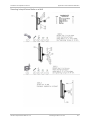
Mounting the ODUs
Notes
To mount the ODU on a pole or a wall:
1.
Ensure that the ODU is properly grounded.
2.
Mount the ODU onto the pole or wall. Ensure that the unit is oriented so that the cable
connectors are at the bottom. (If they are on top, water may penetrate into the unit
causing damage.)
Do not tighten the ODU to its mounting brackets until the alignment process of the
antenna is complete.
Ensure that there are no direct obstructions in front of the ODU or interference from manmade obstacles.
Mounting an External Antenna
To mount an external antenna:
1.
To mount an external antenna ensures that the antenna is properly grounded and
then mounts the antenna onto the pole.
2.
Follow the mounting instructions supplied with the antenna.
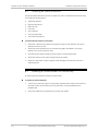
Performing Outdoor Connections
To complete the outdoor connections:
1.
Connect the ground cable to the ODU chassis as marked on the ODU.
2.
Connect the antenna cable(s) to the ODU.
3.
Connect the lightning protection device to the ODU.
4.
Attach the ODU-IDU cable to the ODU RJ-45 connector.
5.
Screw in the cable glands to ensure hermetic sealing of the ODU.
6.
Secure the cables to the pole, mast or brackets using UV-rated cable ties.
Mounting and IDU
To mount an IDU:
1.
If the rack already holds other equipment, ensure that it is properly grounded.
Do not proceed with installation into a “live” rack unless it is properly grounded.
Warning
2.
Attach the rack mounting brackets to the IDU.
3.
Bolt the IDU into an empty slot in the rack, ensuring that it sits securely.
GE MDS Intrepid and Intrepid Ultra
Ver. 2.5
Quick Start Guide
Installation and Operation Manual
4.
Note
Ground the IDU to the rack using grounding lug I. The IDU should be left permanently
grounded.
Instead of using the rack mounting brackets, the IDU may be rail mounted using the four
screw holes on each of its sides.
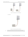
Connecting the ODU to the IDU
To connect the ODU to the IDU:
1.
Route the cable from the ODU to the IDU, secure the cable along its path
2.
Connect the cable to the ODU RJ-45 connector on the IDU.
Connecting User Equipment to the IDU
To connect user equipment to the IDU:
Connect user switch/router or any other compatible device to the IDU panel RJ-45
ports designated LAN.
Aligning ODUs
Warning
To align ODUs with integrated antennas or external bipolar antennas:
1.
For external dual-polarized antennas: Using a coax cable with N-Type connectors,
connect the vertical polarization connector of the antenna to the ANT 1 connector of
the ODU.
2.
For external dual-polarized antennas: Using a coax cable with N-Type connectors,
connect the horizontal polarization connector of the antenna to the ANT 2 connector
of the ODU.
3.
Ensure that power is connected to the IDUs at both sites.
4.
Ensure normal operation of the IDUs by the LED indications on the front panel.
5.
Provided that site A detects the signal from site B, the ODU starts beeping 20 seconds
after power up, and continues beeping until the ODUs are aligned, and the installation
is complete.
6.
In the following steps, “antenna” refers both to an external antenna and an integrated
antenna.
7.
Direct the antenna of site B in the direction of site A. This is simplified if a previous site
survey has been completed and azimuths are known.
When aligning the antennas, do not stand in front of a live antenna.
8.
Make a horizontal sweep of 180 degrees with the site A antenna so that the strongest
signal from site B can be detected.
9.
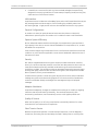
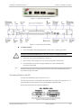
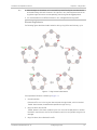
Slowly turn the site A antenna back towards the position of site B, listening to the tone
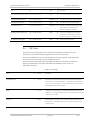
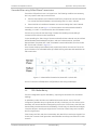
until the best signal is reached. See the following figure for audible signal variations.
GE MDS Intrepid and Intrepid Ultra
Ver. 2.5
Quick Start Guide
Note
Installation and Operation Manual
Three beeps and a pause is 'best signal so far'.
Two beeps and a pause is 'signal quality increased'.
One beep and pause is 'no change in signal'.
Long beep and short pause is 'signal quality decreased'.
One beep and a long pause is 'no air link'.
Any other signal does not relate to antenna alignment.
10. Secure the site A antenna to the pole/wall.
11. Repeat steps 4 to 8 for site B.
GE MDS Intrepid and Intrepid Ultra
Ver. 2.5
Chapter 1
Introduction
1.1
Overview
Intrepid and Intrepid Ultra offer throughput capacity of 25Mbps Full Duplex / 50Mbps
aggregate and 100 Mbps Full Duplex / 200Mbps aggregate for cost-effective point-to-point
broadband wireless transmission device. It transmits native Ethernet and TDM traffic
(TDMoIP) over a variety of bands, and is suitable for licensed and unlicensed deployment.
Product Options
Wireless Link Capacity
Intrepid PtP Systems are available with the following wireless link capacities:
25Mbps Full Duplex / 50Mbps aggregate
100 Mbps Full Duplex / 200Mbps aggregate
Frequencies
MDS Intrepid Products operates in different frequency ranges, with versions for FCC, ETSI
and other regulations.
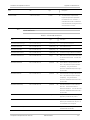
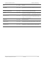
Table 1-1. Supported Frequencies, Regulations and Channel Bandwidths
Channel Bandwidth
Occupied
Frequency
Range [GHz]
Compliance
FCC/IC 2.4
2.402–2.472
FCC/IC 4.9
Band
10 MHz
20 MHz
40 MHz
FCC 47CFR, Part 15, Subpart C and IC RSS-210
Yes
Yes
No
4.940–4.990
FCC 47CFR, Part 90, Subpart Y and IC RSS-111
Yes
Yes
No
FCC/IC 5.3
5.260–5.340
FCC 47CFR, Part 15, Subpart E and IC RSS-210
Yes(*)
Yes
Yes(*)
FCC 5.4
5.480–5.715
FCC 47CFR, Part 15, Subpart E
Yes(*)
Yes
Yes(*)
IC RSS-210
Yes
Yes
Yes
IC 5.4
5.480–5.590
5.660–5.715
FCC/IC 5.8
5.725-5.850
FCC 47CFR, Part 15, Subpart C and IC RSS-210
Yes
Yes
Yes
ETSI 5.3
5.160–5.340
ETSI EN 301 893
Yes
Yes
No
ETSI 5.4
5.480–5.715
ETSI EN 301 893
Yes
Yes
Yes
Intrepid and Intrepid Ultra Ver. 2.6
Overview
1-1
Chapter 1 Introduction
Installation and Operation Manual
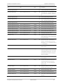
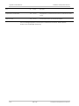
Channel Bandwidth
Occupied
Frequency
Range [GHz]
Compliance
ETSI 5.8
5.735–5.865
WPC India 5.8
MII China 5.8
Band
10 MHz
20 MHz
40 MHz
ETSI EN 302 502
Yes
Yes
No
5.825–5.875
GSR-38
Yes
Yes
Yes
5.730–5.845
MII China
Yes
Yes
Yes
Note
For FCC 5.4 and FCC/IC 5.3 bands: To comply with FCC regulations do not select channel
bandwidths of 10 and 40 MHz.
Features
Wireless Link
Intrepid Series Radios delivers up to 100 Mbps air rate for Ethernet and E1/T1 traffic. The
system supports a variety of spectrum bands.
Capacity
The two Intrepid Series models with different Ethernet or aggregate throughputs are
available:
Intrepid Ultra
Max 100 Mbps FD / 200 Mbps Aggregate,
Ethernet and up to 16 E1/T1 ports
Intrepid
Max 25 Mbps FD / 200 Mbps Aggregate
Ethernet and up 8 E1/T1s ports
Transmission Technologies
Using the following technologies, the Intrepid Series air interface is designed to ensure
nonstop, high quality transmission, even under interference and harsh conditions
1-2
Automatic Adaptive Rate (AAR) is a mechanism that dynamically adapts the air
interface rate by changing both the signal modulation and coding.
Automatic Channel Selection (ACS) chooses the best channel by monitoring the
available radio channels and dynamically selecting a channel which is best suited for
transmission at any given time.
Automatic Repeat Request (ARQ) is a mechanism for error control during data
transmission. When the receiver detects an error in the received information, it
automatically requests the transmitter to resend the information. This process is
repeated until the transmission is error free or the error continues beyond a
predetermined number of maximum transmissions. Intrepid Series ARQ mechanism is
optimized for time-critical traffic.
Overview
Intrepid and Intrepid Ultra Ver. 2.6
Installation and Operation Manual
Chapter 1 Introduction
Forward Error Correction (FEC) with very low overhead and algorithms specifically
designed for the varying conditions of license-exempt frequency bands, ensuring fast,
robust and error-free communications.
LAN Interface
Intrepid Series IDUs includes two 10/100BaseT ports and one SFP-based Fast Ethernet port
with autonegotiation and VLAN support. Traffic handling is provided by a MAC-level
self-learning bridge. Single port PoE units are also available for Ethernet-only systems.
Physical Configurations
An outdoor unit (ODU), an optional external antenna and an indoor unit (IDU) with
redundant DC power supplies. The outdoor unit is suitable for mast or wall installation.
Superior Spectral Efficiency
Built on advanced MIMO and OFDM technologies, the Intrepid Series system provides a
high-capacity link at the 10, 20 MHz channel bandwidths for Intrepid and 10, 20 , 40 MHz
bandwidths for Intrepid Ultra.
These channels support high robustness of the air interface under interference and harsh
conditions. In countries where applicable, narrow channel bandwidth reduces the cost of
the spectrum license.
Security
AES 128-bit integrated advanced encryption support provides enhanced air interface
security for carriers and private networks. It ensures user data protection with one of the
most sophisticated commercially available combined encryption and authentication
techniques, CCM/AES. This technique combines message authentication (preventing antispoofing and replay protection) with commercial encryption, and complies with the IEEE
802.11i (phase iii) security recommendations.
CCM/AES uses a symmetric 128-bit encryption key (EK), and a nonce, and provides both
message encryption and authenticating signature. The nonce mechanism enables the
receiver to remember already received genuine messages and reject all replayed
messages.
Adaptive Modulation
Intrepid Series adaptively changes the modulation according to air conditions, targeting
maximum rate while maintaining link stability. The rate drops temporarily after
encountering interference, then automatically returns to the highest possible rate.
Quality of Service
When the link quality is out of limits, Intrepid Series automatically searches for a clear
channel within a pre-selected list of frequencies.
Short Time-to-Service
Because Intrepid Series operates in license-exempt frequencies, it can be deployed in
record time, eliminating the costs and delays involved in leasing lines or trenching fiber.
Intrepid and Intrepid Ultra Ver. 2.6
Overview
1-3
Chapter 1 Introduction
Installation and Operation Manual
Ethernet Ring
Ethernet rings are used to protect data against link and node failures. The rings ensure
high availability of Ethernet services for critical applications.
VLAN Management
VLAN management allows the separation of user traffic from NMS traffic. The user decides
if such a separation is required. Both the headquarters and remote sites are configured
with VLAN management.
Ethernet QoS
VLAN- or Diffserv-based traffic prioritization technique is used for forwarding user Ethernet
traffic into four weighted queues. The queues handle traffic with different service demands
(real-time, near real-time, controlled loaf and best effort).
Monitored Hot Standby (MHS)
The Monitored Hot Standby (MHS) protects up to sixteen E1/T1 services with Intrepid Ultra
and up to four E1/T1 services with Intrepid . It is designed to provide high reliability highcapacity point-to-point links. The MHS is:
Designed to provide redundancy and high reliability for carrier class operators
Optimized for high capacity links operating in license-free bands
A comprehensive solution providing protection against both equipment failure and
loss of air interface, by simple connectivity between a primary link and a secondary
link
Able to use a different band for maximum protection to the air interface
The main features of the MHS are:
Fully automatic switchover from the primary to the secondary link in less than than 50
ms
Automatic restoration to primary link as soon as it becomes available
MHS supports TDM services; Ethernet services are carried by both links independently.
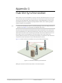
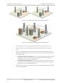
Hub Site Synchronization
When several Intrepid Series units are collocated at a common hub site interference may
occur from one unit to another. The ODU units are supplied with special hardware for the
collocation of up to eight units.
Using a method called Hub Site Synchronization (HSS) an external cable is connected to all
collocated Intrepid Series units , this cable carries pulses sent to each ODU, which
synchronize their transmission with each other.
Diversity
Intrepid Series links using dual bipolar antennas may be configured to transmit the same
data through both radios. This feature provides added data transmission inegrity under
harsh conditions.
1-4
Overview
Intrepid and Intrepid Ultra Ver. 2.6
Installation and Operation Manual
Chapter 1 Introduction
Management
A single SNMP-based network management application (Airmux Manager) is used to control
multiple Intrepid Series radions as a unified network.
VLAN management allows the separation of user traffic from NMS traffic. The user decides
if such a separation is required. Both the headquarters and remote sites are configured
with VLAN management.
Factory settings can be restored at any time for each ODU.
Information on links and management can be collected and analyzed via a single action.
Spectrum View displays a visual representation of spectrum avail-ability during the link
installation. It is an RF survey tool supporting the link installation prior to service activation.
Use Spectrum View to choose the operating channel.
1.2
Physical Description
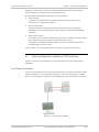
An Intrepid Series system may consist of an Outdoor Unit (ODU) and an Indoor Unit or an
outdoor PoE housed in a weather-proof enclosure.
Figure 1-1. Intrepid Series IDU and ODUs
Outdoor Unit (ODU)
The ODU is the radio transceiver of the Intrepid Series system. It supports two radios for
MIMO operation. The ODU may be mounted on a pole or a wall, and connects to the IDU or
PoE device using a Cat.5e cable.
Intrepid and Intrepid Ultra Ver. 2.6
Physical Description
1-5
Chapter 1 Introduction
Installation and Operation Manual
ODUs are available as:
Note
Integrated Antenna ODU. This ODU has an integrated 370 mm (1.2ft) flat panel
antenna. The ODU contains both the radio and the antenna as a single unit housed in
a weatherproof case.
Connectorized ODU. This ODU has 2 N-type connectors for connecting an external
antenna.
The external antenna choices are:
Single Dual-Polarized antenna
Optional - Two Single-Polarized antennas
Optional – Single Single-Polarized antenna – Reduces Throughput by 50%
Indoor Units (IDUs)
The IDUs have the service ports and provide aggregation of these services towards the
ODU that transports them over the air. The IDUs also provide power to the ODU.
Figure 1-1 shows typical Intrepid Series indoor IDU-E and ODU.
8.5” IDU provide up to two Ethernet ports and up to two E1/T1 interfaces.
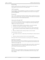
Power Over Ethernet (PoE) Devices
The basic PoE device provides Ethernet service only, with power for the ODU. The PoE
device is extremely compact, having one Ethernet port, one ODU port and a standard 3-pin
male AC power socket.
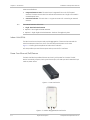
Figure 1-2. Basic PoE Device
Figure 1-3. Outdoor (Ruggedized) DC PoE Device
1-6
Physical Description
Intrepid and Intrepid Ultra Ver. 2.6
Installation and Operation Manual
Chapter 1 Introduction
Antennas
An antenna is the radiating and receiving element from which the radio signal, in the form
of RF power, is radiated to its surroundings and vice versa. The antenna gain and
transmitting power may be limited by country regulations.
Intrepid Series may be operated with an integrated antenna that is part of the ODU unit, or
with external antennas connected to the ODU via N-type connectors. All cables and
connections must be connected correctly to reduce RF losses. The required antenna
impedance is 50.
The 5.x GHz Integrated Antenna ODU is provided with 370 mm (1.2ft) flat panel antenna,
with a gain of 23dBi (5.x GHz) / 19 dBi (4.9 GHz) and 8° beam width. The 2.x GHz Integrated
Antenna ODU is provided with 370 mm (1.2ft) flat panel antenna, with a gain of 16 dBi and
16° beam width. The radio and the antenna are housed in a weatherproof case as a single
unit.
Figure 1-4. ODU with Integrated Flat Panel Antenna
External antennas are available for the Intrepid Series radios, varying in operating
frequencies, form factor, size and gain, dual or single polarization.
The flat panel antennas shown below can be used either as an integrated or external
antenna.
Figure 1-5. External Antennas for Use with Intrepid Series
GSU
The GPS-based synchronization unit (GSU) is designed to handle inter-site interferences
under large-scale deployment scenarios.
Intrepid and Intrepid Ultra Ver. 2.6
Physical Description
1-7
Chapter 1 Introduction
Installation and Operation Manual
The GSU is an outdoor unit consisting of a standard wireless link enclosure, a GPS antenna
and a PoE device.
The GSU is connected to the HSS unit using a standard HSS cable. It synchronizes the
transmission timing of multiple hub sites to the same clock source thus eliminating mutual
interference.
Figure 1-6. General GSU Configuration
1.3
Functional Description
Intrepid Series system comprises of the following units:
Outdoor Unit (ODU): An enclosed aluminum frame with a front sealed plastic cover,
containing an integrated transceiver with an antenna, RF module, modem and
standard interfaces. The ODU stores all the configuration parameters of the Intrepid
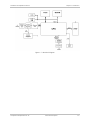
Series system. Figure 1-7 shows the ODU block diagram.
Indoor Unit (IDU): The interface unit between the ODU and the user. It converts 100–
240 VAC to -48 VDC, and sends it on to the ODU. The IDU does not store any
configuration data. Therefore, there is no need for additional configuration of the
Intrepid Series system when replacing an IDU.
Outdoor PoE (O-PoE): An enclosed aluminum frame with a front sealed aluminum
cover, containing a 110–220 VAC to 48 VDC switching power supply and an interface
interconnecting an un-powered Ethernet infrastructure to ODU.
1-8
Functional Description
Intrepid and Intrepid Ultra Ver. 2.6
Installation and Operation Manual
Chapter 1 Introduction
Figure 1-7. ODU Block Diagram
Intrepid and Intrepid Ultra Ver. 2.6
Functional Description
1-9
Chapter 1 Introduction
1.4
Radio
Installation and Operation Manual
Technical Specifications
Frequency Bands (GHz)
See Table 1-1
Throughput
100 Mbps FD / 200Mbps Agg. - Ethernet and up to 16 E1/T1
25 Mbps FD / 50 Mbps Aggf. - Ethernet and up 8 E1/T1
Channel Bandwidth
10, 20 MHz channel bandwidths for Intrepid
10, 20 , 40 MHz bandwidths for Intrepid Ultra.
Duplex Technique
TDD
Modulation
22 MIMO-OFDM (BPSK, QPSK, 16 QAM, 64 QAM), see
Table 1-2
Transmit Power
See Table 1-2
Sensitivity
See Table 1-2 (measured at BER <10E-11, 20 MHz)
Error Correction
FEC, k = 1/2, 2/3, 3/4, 5/6, see Table 1-2
Encryption
AES 128
Regulation
FCC/IC:
FCC 47CFR, Part 15, Subpart C,
FCC 47CFR, Part 15, Subpart E
FCC 47CFR, Part 90, Subpart Y
RSS-111
IC RSS-210
ETSI:
ETSI EN 302 502
ETSI EN 301 893
WPC India: GSR-38
China: MII
1-10
Technical Specifications
Intrepid and Intrepid Ultra Ver. 2.6
Installation and Operation Manual
Antennas
TDM Interface
Chapter 1 Introduction
Characteristics
Table 1-3
Polarization Type
Dual
Number of Ports
IDU – 2
IDU-E – 0, 4, 8 or 16
Type
E1/T1, configurable
Framing
Unframed (transparent)
Timing
Independent timing per port, Tx and Rx
Connector
RJ-45
Standards Compliance
ITU-T G.703, G.826
Line Code
Latency
Impedance
LAN Interface
HDB3 (E1)
B8ZS/AMI (T1)
Configurable 5–20 ms
E1: 120Ω, balanced,
T1: 100Ω, balanced
Jitter and Wander
According to ITU-T G.823, G.824
Number of Ports
IDU – 2
IDU-E – 3
Type
2 ports – 10/100BaseT
1 port – Fast Ethernet SFP
Framing/Coding
IEEE 802.3u
Bridging
Self-learning, up to 2048 MAC addresses
Traffic Handling
MAC layer bridging, self-learning
Latency
3 msec (typical)
Line Impedance
100 (10/100BaseT)
VLAN Support
Yes
Connector
RJ-45 (10/100BaseT)
LC (SFP-based)
Intrepid and Intrepid Ultra Ver. 2.6
Technical Specifications
1-11
Chapter 1 Introduction
Management
Indicators
Alarm
Connector
Power
Physical
Environment
Installation and Operation Manual
Application
PulseNet
Protocol
SNMP, Telnet
PWR (green)
Power status (IDU only)
IDU (green)
IDU-E status
ODU (green/red)
ODU-to-IDU link status
AIR I/F (green/red)
Link status
SVC (green/red)
E1/T1 signal status
HSS
HSS status
STBY
Standby mode status
Connector
DB-25 female
Electrical Characteristics
Dry contact, 30V/2A
Max input current, 0.01A at 0.5W (R=5K)
DC
-20 to -60 VDC (24 VDC or 48 VDC nominal) via AC/DC
converter
Power Consumption
35W max (ODU with IDU)
Connector
3-pin terminal block
ODU (with integrated
antenna)
Height: 371 mm (14.8 in)
Width: 371 mm (14.8 in)
Depth: 9 mm (3.6 in)
Weight 3.5 kg (7 lb)
IDU
Height: 45 mm (1.7 in)
Width: 436 mm (17.2 in)
Depth: 210 mm (8.3 in)
Weight 1.5 kg (3.3 lb)
Temperature
ODU: -35°C to +60°C (-31°F to +140°F)
IDU: 0°C to +50°C (32°F to +122°F)
Humidity
ODU: Up to 100% non-condensing, IP67
IDU: Up to 90%, non-condensing
1-12
Technical Specifications
Intrepid and Intrepid Ultra Ver. 2.6
Installation and Operation Manual
Chapter 1 Introduction
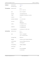
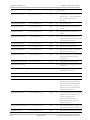
Table 1-2. Radio Link Characteristics
Modulation
BPSK
QPSK
16 QAM
64 QAM
Rate
FEC
Max Tx Power
Sensitivity
Single Antenna
Dual Antenna
[Mbps]
[Mbps]
[k = ]
6.5
13
1/2
13
26
1/2
19.5
39
3/4
26
52
1/2
24
25
-81
39
78
3/4
21
24
-77
52
104
2/3
19
24
-72
58.5
117
3/4
21
-70
65
130
5/6
20
-67
4.8–6 GHz
2.4 GHz
[dBm]
[dBm]
-88
25
26
-86
-83
18
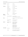
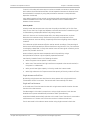
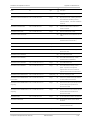
Table 1-3. Antenna Options
Antenna
Frequency
Gain
Beam
Dimensions
Weight
Connector
[GHz]
[dBi]
[degrees]
[mm]
[inch]
[kg]
[Ib]
4.9x–5.875
19 (4.9x GHz)
9
37137140
14141.5
2.5
5.5
2 × N-type
Type
Integrated
Flat panel
23 (5.x GHz)
Flat panel
2.40
16
16
37137140
14141.5
2.5
5.5
2 × N-type
Flat panel
2.40–2.70
19
16
37137140
14141.5
2.5
5.5
2 × N-type
Flat panel
4.40–5.10
22.8
10
37137140
14141.5
2.5
5.5
2 × N-type
Flat panel
4.90–5.80
20.5 (4.90–5.00 GHz)
8
37137140
14141.5
2.5
5.5
2 × N-type
9
37137140
14141.5
2.5
5.5
2 × N-type
9
37137140
14141.5
2.5
5.5
2 × N-type
5.6
Diam. 600
Diam. 23.6
7.0
15.4
2 × N-type
External
22 (5.00–5.80 GHz)
Flat panel
4.90–6.06
22.5 (5.15–5.25 GHz)
23 (5.25–5.875 GHz)
21.5 (5.875–6.00 GHz)
Flat panel
5.7–6.06
23 (5.70–5.875 GHz)
21.5 (5.875–6.06 GHz)
Dish
4.90–6.06
28 (low band)
28.5 (mid band)
30 (high band)
Note
The range of the system depends on the system configuration. For further information,
contact the GE MDS partner nearest you or one of GE MDS offices worldwide.
Intrepid and Intrepid Ultra Ver. 2.6
Technical Specifications
1-13
Chapter 2
Installation and Setup
This section describes the installation, alignment, and setup procedures for an Intrepid
Series Radio system.
After installing the hardware and establishing a link, refer to Chapter 3 for operation
instructions and Chapter 4 for configuration instructions.
In case a problem is encountered, refer to Chapter 5 for test and diagnostic instructions.
Internal settings, adjustment, maintenance, and repairs may be performed only by a
skilled technician who is aware of the hazards involved.
Warning
Note
Always observe standard safety precautions during installation, operation, and
maintenance of this product.
Before installing the product, review Handling Energized Products at the beginning of the
manual.
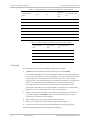
2.1
Warning
Safety Practices
Outdoor units and antennas should be installed ONLY by experienced installation
professionals who are familiar with local building and safety codes and, wherever
applicable, are licensed by the appropriate government regulatory authorities. Failure
to do so may expose the end user or the service provider to legal and financial
liabilities. GE MDSand its resellers or distributors are not liable for injury, damage or
violation of regulations associated with the installation of outdoor units or antennas.
Preventing Overexposure to RF Energy
To protect against overexposure to RF energy, install the ODUs so as to provide and
maintain minimal separation distances from all persons.
When the system is operational, avoid standing directly in front of the antenna. Strong RF
fields are present when the transmitter is on. The ODU must not be deployed in a location
where it is possible for people to stand or walk inadvertently in front of the antenna.
Warning
Do not activate indoors an ODU with an integrated or external antenna. To test an
active radio link inside the building, use an attenuated RF cable (at least 40 dB) for the
ODU connection.
Intrepid and Intrepid Ultra Ver. 2.6
Safety Practices
2-1
Chapter 2 Installation and Setup
Installation and Operation Manual
Table 2-1. Safety Distances for Intrepid Series Radio FCC and IC Products
IC ID
Antenna
Gain
[dBi]
Min. Safety Distance
[cm]
Q3KRW2058
5100A-RW2054
28
223
5.8
Q3KRW2058
5100A-RW2054
24
141
5.3/5.4
Q3KRW2054
5100A-RW2054
23.5 / 28
20
4.9
Q3KRW2049
5100A-RW2054
28
225
4.9
Q3KRW2049
5100A-RW2054
21
113
2.4
Q3KRW2024
5100A-RW2054
19
39
2.4
Q3KRW2024I
5100A-RW2024I
17.5
40
Frequency Band
[GHz]
FCC ID
5.8
Table 2-2. Safety Distances for Intrepid Series Radio ETSI Products
Frequency Band
[GHz]
Antenna Gain
[dBi]
Min. Safety Distance
[cm]
5.8
24 / 28
16
5.4
23.5 / 28
9
5.3
23.5 / 28
4
2.4
19 / 17.5
3
Grounding
All GE MDSproducts should be grounded during operation. In addition:
The ODU should be earthed by a wire with diameter of at least 12 AWG.
The Intrepid Series Radio ODU must be properly grounded to protect against lightning.
It is the user's responsibility to install the equipment in accordance with Section 810 of
the National Electric Code, ANSI/NFPA No.70-1984 or Section 54 of the Canadian
Electrical Code. These codes describe correct installation procedures for grounding the
outdoor unit, mast, lead-in wire and discharge unit. It also lays down the size of
grounding conductors and connection requirements for grounding electrodes.
The Intrepid Series Radio ODU must be grounded to a protective earth as described in
Appendix D and in accordance with the local electrical regulations.
The earth lug on the IDUE should be connected to the protective earth at all times, by
a wire with a diameter of 18 AWG or wider. Rack-mounted equipment should be
mounted only in earthed racks and cabinets.
Always make the ground connection first and disconnect it last
Never connect telecommunication cables to ungrounded equipment
Ensure that all other cables are disconnected before disconnecting the ground.
More detailed grounding guidelines are supplied in Appendix D.
2-2
Safety Practices
GE MDS Intrepid and Intrepid Ultra Ver. 2.6
Installation and Operation Manual
Chapter 2 Installation and Setup
Protection against Lightning
The use of lightning protection is dependent on regulatory and end user requirements. All
outdoor units are designed with surge limiting circuits to minimize the risk of damage due
to lightning strikes. GE MDS recommends the use of additional surge arrestor devices to
protect the equipment from nearby lightning strikes.
See Appendix D for detailed installation instructions of lightning protection devices.
It is recommended that installation of the outdoor unit be contracted to a professional
installer.
Before working on equipment connected to power lines or telecommunication lines,
you should remove jewelry or any other metallic object that may come into contact
with energized parts.
Use extreme care when installing antennas near power lines.
Use extreme care when working at heights.
When using an AC power source for Intrepid Series Radio always use the AC power
adapter supplied by GE MDS.
Use the right tools. In addition to standard tools required for any kind of ODU or
antenna installation, Intrepid Series Radio requires additional specific tools detailed in
the Additional Equipment Required section below.
2.2
Site Requirements and Prerequisites
For the IDU units, allow at least 90 cm (36 in) of frontal clearance for operating and
maintenance. Allow at least 10 cm (4 in) clearance at the rear of the unit for signal lines
and interface cables.
The ambient operating temperature should be –35 to 60C (–31 to 140F) (ODU), or 0 to
50C (32 to 122F) (IDU) at a relative humidity of up to 100% (ODU) or 90% (IDU),
non-condensing.
2.3
Package Contents
The Intrepid Series Radio packages include the following items:
ODU package containing:
One ODU, see Figure 2-1, Figure 2-2
An ODU mounting kit
Label showing the MAC address and the alternative community string. The label is
self-adhesive. You should keep this label safe.
Cable glands (to be used with the ODU-IDU cable).
Intrepid and Intrepid Ultra Ver. 2.6
Package Contents
2-3
Chapter 2 Installation and Setup
Installation and Operation Manual
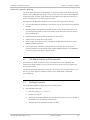
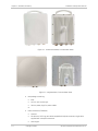
Figure 2-1. Connectorized ODU, Front and Rear Views
Figure 2-2. Integrated ODU, Front and Rear Views
IDU package containing:
IDUE
19-inch rack mounting kit
Two DC power plugs for power cables.
Or
2-4
External antenna (if ordered)
Antenna
RF cable 1m (3 ft) long; two cables supplied with bipolar antennas, single cable
supplied with monopolar antennas
Mounting kit.
Package Contents
GE MDS Intrepid and Intrepid Ultra Ver. 2.6
Installation and Operation Manual
2.4
Chapter 2 Installation and Setup
Additional Equipment Required
The following is a list of the equipment and materials required to install Intrepid Series
Radio hardware.
2.5
Tools and materials:
Crimping tool for RJ-45 (if the ODU-IDU cable is without connectors)
Spanner/wrench 13 mm (0.5 in)
Drill (for wall mounting only)
Cable ties
Sealing material
Cables and connectors:
ODU grounding cable 12 AWG
IDU grounding cable 18 AWG
ODU-IDU cable (outdoor class, CAT-5e, 4 twisted pairs, 24 AWG)
Ethernet cross cable (PoE-based links).
Installation Sequence
Install the Intrepid Series Radio system according to the following the steps:
1.
Survey the site
2.
Mount the ODUs, see Appendix B
3.
Mount the external antennas (if used), see Appendix B
4.
Mount the lightning protection devices (if used), see Appendix D
5.
Perform outdoor connections, see Outdoor Connections
6.
Mount the IDUs, see Mounting the IDUs.
7.
Perform indoor connections, Connecting the ODU to the IDU.
8.
Align the ODUs/antennas, page
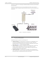
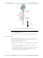
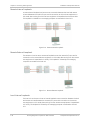
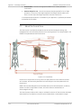
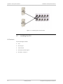
Figure 2-3 illustrates a typical installation of Intrepid Series Radio with an external antenna.
Intrepid and Intrepid Ultra Ver. 2.6
Installation Sequence
2-5
Chapter 2 Installation and Setup
Installation and Operation Manual
Figure 2-3. Typical Installation Diagram (with External Antenna)
2.6
Surveying the Site
This section explains how to survey the site intended for Intrepid Series Radio installation.
Planning the Link Site
Link site planning consists of a set of surveys, which must be carried out before any
equipment is brought to the site. If for some reason, the outcome of any of these surveys is
negative, site re-location will need to be considered.
A site survey consists of three stages:
2-6
Preliminary survey – The proposed link is analyzed in the office using a topographic
map.
Physical survey – The locations of the Intrepid Series Radio indoor and outdoor
equipment are determined on-site.
Radio Frequency (RF) survey – It is recommended that the installation area be scanned
with a spectrum analyzer, to identify RF interference so as to determine a clear
channel for Intrepid Series Radio installation (on-site).
Surveying the Site
GE MDS Intrepid and Intrepid Ultra Ver. 2.6
Installation and Operation Manual
Chapter 2 Installation and Setup
Site Survey
Intrepid Series Radio wireless links must be planned before installation. The designated
installation site must be appraised to determine that the wireless system is able to operate
efficiently and provide connectivity without signal degradation.
Intrepid Series Radio offers a wide operating frequency range. A free frequency channel
must be determined within the operating range, for optimum performance.
Recommended equipment:
Stage 1 (preliminary survey)
Topological map of the area
Urban map of the area
Compass
Stage 2 (physical survey)
100 meter tape measure
Ohmmeter, to check ground connection
Binoculars
Map
Digital camera
Paper, pencil, and a clipboard
GPS device (optional)
Compass (optional)
Stage 3 (RF survey)
Spectrum analyzer with Max Hold function and screen capture facility that can
store multiple images, for documentation purposes
RF accessories (connectors and cables)
Communication devices (for example, cellular phones, or a set of walkie talkies).
Stage 1 (Preliminary Survey)
A preliminary survey is necessary before visiting potential installation sites. As much detail
as possible should be obtained about the two designated ODU installation sites and the
area between them.
To perform a preliminary survey:
1.
Mark the two designated installation sites on a topographic map of the area.
2.
Measure the distance between the sites; check that it is within the specified range of
Intrepid Series Radio.
3.
On the urban map, check for developed areas situated between the two installation
sites. Pay attention to these areas when performing the physical site survey; there may
be tall buildings, RF towers, or transmitters, which could cause interference to the link.
4.
Check the area between the two sites for obstructions such as:
High ground - hills or mountains
Intrepid and Intrepid Ultra Ver. 2.6
Surveying the Site
2-7
Chapter 2 Installation and Setup
Installation and Operation Manual
Lakes or large bodies of water. Water has a reflection effect on RF signals like a
building. This type of reflection causes the received amplitude to be reduced. As a
rule of thumb, the presence of a large body of water between the link sites may
double the required antenna height.
5.
Determine and record the compass bearings between both ODUs, relative to north.
6.
If there are obstructions between the two sites, calculate the Fresnel Zone (see
Appendix C for details).
7.
If the site chosen does not meet requirements, consider alternative sites.
8.
Use the Link Budget Calculator (on the CD supplied with Intrepid Series Radio or using
the Link Manager) to determine the expected performance.
Stage 2 (Physical Survey)
The physical site survey reviews the environment of the proposed Intrepid Series Radio
installation location, to ensure that the link sites are suitable for the wireless network. The
results of the physical site survey should be recorded.
Note
It is advisable to go on a clear day, so you can more easily see any obstructions between the
two sites.
Note
To perform a physical survey:
1.
From the compass readings taken in the preliminary survey, find the azimuth
(horizontal position) that the ODU should face towards the second ODU.
2.
Using binoculars, locate any obstructions such as tall trees, high buildings, hills or
mountains. Look for other RF towers between the two sites. Mark the locations of the
obstructions on the map.
3.
Determine the location for the ODU (having regard for existing rooftop installations
and tower space). It should be above any obstructions, considering the Fresnel Zone
(see Appendix C).
4.
If you need to install the ODU on a tower, make sure that the tower is far away from
overhead electric power lines.
5.
Determine a location for the indoor equipment; it should be as close as possible to the
ODU. At an existing site, there is probably an equipment room with cable-routing
channels.
The IDU–ODU cable length limit is 100m, in accordance with IEEE 10/100BaseT
requirements.
6.
Measure and record the path length of the cable from the ODU position to the indoor
equipment room.
7.
Determine the ground and lightning connection points of the installation. The Intrepid
Series Radio ODU and IDU must both be grounded.
8.
Using the ohmmeter, measure and record the resistance of the required installation to
the grounding point. The resistance must be less than 10.
9.
Review the results of the physical site survey. Decide if the site is suitable for the
Intrepid Series Radio wireless network installation.
2-8
If the site is suitable, continue with stage 3, the RF survey
Surveying the Site
GE MDS Intrepid and Intrepid Ultra Ver. 2.6
Installation and Operation Manual
Chapter 2 Installation and Setup
If the site is not suitable, survey another site.
Stage 3 (RF Survey)
The RF survey examines the wireless environment of the Intrepid Series Radio installation
site, to determine whether there are available channels within the Intrepid Series Radio
operating frequency band. An RF survey is performed using a spectrum analyzer.
It is advisable to familiarize yourself with the spectrum analyzer before going out on site,
specifically the Max Hold and Marker functions.
You should perform the RF survey at both proposed link sites.
The survey should be carried out during a busy time of day, to best judge the worst-case
radio interference. Allow 2–4 hours duration for a good RF survey.
Note
It is possible to install the Intrepid Series Radio link and use the Link Manager to find a clear
channel. Each frequency channel can be evaluated in turn. Achievement of a clear channel is
indicated by the Quality bar on the Channel Setting window becoming green.
2.7
Outdoor Installation
Mounting the ODU
The ODU can be mounted on a pole or a wall. In both installations, the supplied mounting
kit is used to secure the ODU.
Note
A mast-sited ODU typically uses a pole attached to the mast.
An Intrepid Series Radio link operates in pairs of two ODUs with the same configuration.
Both ODUs must be installed, and the antennas aligned for maximum throughput.
Prior to connecting cables to the ODU, the protective earth terminal (screw) of the ODU
must be connected to an external protective ground conductor or to a grounded pole.
Only a qualified person using the proper safety equipment should climb the
antenna mast
Warning
Only qualified professional personnel should install or dismantle ODUs and masts.
Notes
To mount the ODU on a pole or a wall:
1.
Ensure that the ODU is properly grounded.
2.
Mount the ODU onto the pole or wall. Ensure that the unit is oriented so that the cable
connectors are at the bottom. (If they are on top, water may penetrate into the unit
causing damage.) It is possible to mount an ODU horizontally.
3.
Refer to Appendix B for detailed ODU mounting kit contents and schematics.
Do not tighten the ODU to its mounting brackets until the alignment process of the
antenna is complete.
Ensure that there are no direct obstructions in front of the ODU or interference from manmade obstacles.
Intrepid and Intrepid Ultra Ver. 2.6
Outdoor Installation
2-9
Chapter 2 Installation and Setup
Installation and Operation Manual
Mounting External Antennas
If you are using ODU with an integrated antenna, skip to Mounting the Lightning Protection
Devices below.
The supplied mounting kit is used to mount the antenna onto a pole. The antennas must be
aligned for maximum throughput.
Do not stand in front of a live antenna.
Warning
To mount an external antenna:
1.
To mount an external antenna ensures that the antenna is properly grounded and
then mounts the antenna onto the pole. Refer to Appendix B for detailed antenna
mounting instructions.
2.
Follow the mounting instructions supplied with the antenna.
Mounting the Lightning Protection Devices
The use of lightning protection is dependent on regulatory and end user requirements. The
Intrepid Series Radio ODU is designed with surge limiting circuits to minimize the risk of
damage due to lightning strikes. GE MDS recommends the use of additional surge arrestor
devices to protect the equipment from nearby lightning strikes.
Refer to Appendix D for detailed installation instructions of lightning protection devices.
Outdoor Connections
Connect the outdoor devices once they are installed.
To complete the outdoor connections:
1.
Connect the ground cable to the ODU chassis as marked on the ODU.
2.
Connect the antenna cable(s) to the ODU.
3.
Connect the lightning protection device to the ODU (see Appendix D).
4.
Attach the ODU-IDU cable to the ODU RJ-45 connector (see Appendix A)for the
connector pinout)
5.
Screw in the cable glands to ensure hermetic sealing of the ODU.
6.
Secure the cables to the pole, mast or brackets using UV-rated cable ties.
2.8
Indoor Installation
Mounting the IDUs
The Intrepid Series Radio IDUs can be placed on a desktop or mounted in a rack. The
figures below illustrate typical IDU panels. There may be differences in panels depending
on the hardware ordered.
2-10
Indoor Installation
GE MDS Intrepid and Intrepid Ultra Ver. 2.6
Installation and Operation Manual
Chapter 2 Installation and Setup
Figure 2-4. Typical IDU Rear Panel
Figure 2-5. Typical IDU-E Front Panels
To mount an IDU-E:
1.
If the rack already holds other equipment, ensure that it is properly grounded.
Do not proceed with installation into a “live” rack unless it is properly grounded.
Warning
Note
2.
Attach the rack mounting brackets (K) to the IDU-E.
3.
Bolt the IDU-E into an empty slot in the rack, ensuring that it sits securely.
4.
Ground the IDU-E to the rack using grounding lug I. The IDU should be left
permanently grounded.
Instead of using the rack mounting brackets, the IDU-E may be rail mounted using the four
screw holes on each of its sides.
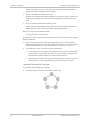
Connecting Power to the IDU
The IDUE has redundant power connection circuits.
The connectors are 3 pin in line female, with polarities (left to right) minus, ground, plus. To
avoid damage to the IDU, always use an AC/DC adapter supplied by RAD.
Ensure that the IDUs at both sites are powered up.
Figure 2-6. IDUE Power Connectors
Intrepid and Intrepid Ultra Ver. 2.6
Indoor Installation
2-11
Chapter 2 Installation and Setup
Installation and Operation Manual
Connecting the ODU to the IDU
The ODU-IDU cable conducts all the user traffic between the IDU and the ODU, and also
provides power to the ODU. The maximum length of the ODU-IDU cable is 100m (328 ft) in
accordance with 10/100BaseT standards.
The ODU-IDU cable is supplied pre-assembled with RJ-45 connectors, at the length
specified when ordering, or as a cable drum with spare connectors. If the ODU-IDU cable
was not ordered, use an outdoor class, CAT-5e 24 AWG shielded cable. See Appendix A for
wiring specifications.
To connect the ODU to the IDU:
1.
Route the cable from the ODU to the IDU, secure the cable along its path
2.
Connect the cable to the ODU RJ-45 connector on the IDU.
Installing a Link using PoE Devices
The PoE device is a simple unit having a power input connector and two Ethernet ports. It is
AC powered, and has a power LED.
To prepare a link using PoE devices:
1.
To connect the ODU to the PoE device, route the cable from the ODU to the PoE device,
secure the cable along its path and connect the cable to the P-LAN-OUT RJ-45
connector on the PoE device.
2.
Connect it to AC power.
3.
Repeat steps 1 to 2 for the second link.
Connecting to Ethernet Equipment
To connect Ethernet user equipment to the IDU:
Note
Connect user switch/router or any other compatible device to the IDU panel RJ-45 or
SFP ports designated LAN. Refer to Appendix A, for RJ-45 connector pinout.
Do not connect two LAN ports to the same network, or flooding may occur.
To connect user equipment to the PoE device:
Connect a user switch, router or any other compatible device to the PoE device RJ-45
port designated LAN-IN. Refer to Appendix A for connector pinout.
Connecting to E1/T1 Equipment
E1/T1 devices are connected to Intrepid Series Radio via balanced RJ-45 ports designated
TRUNK. There may be multiple trunk ports available depending on unit ordered.
Refer to Appendix A for the E1/T1 connector pinout.
To connect E1/T1 equipment to the IDU:
2-12
Connect Intrepid Series Radio to the E1/T1 devices using standard straight E1/T1
cables.
Indoor Installation
GE MDS Intrepid and Intrepid Ultra Ver. 2.6
Installation and Operation Manual
2.9
Chapter 2 Installation and Setup
Connecting and Aligning ODUs / Antennas
You perform antenna alignment using the ODU's audible tone. To speed up the installation
time, alignment of an Intrepid Series Radio system should be performed by two teams
simultaneously, at site A and at site B.
Warning
To align ODUs with integrated antennas or external bipolar antennas:
1.
For external bipolar antennas: Using a coax cable with N-Type connectors, connect
the vertical polarization connector of the antenna to the ANT 1 connector of the ODU.
2.
For external bipolar antennas: Using a coax cable with N-Type connectors, connect
the horizontal polarization connector of the antenna to the ANT 2 connector of the
ODU.
3.
Ensure that power is connected to the IDUs at both sites.
4.
Ensure normal operation of the IDUs by the LED indications on the front panel.
5.
Provided that site A detects the signal from site B, the ODU starts beeping 20 seconds
after power up, and continues beeping until the ODUs are aligned, and the installation
is complete.
6.
In the following steps, “antenna” refers both to an external antenna and an integrated
antenna.
7.
Direct the antenna of site B in the direction of site A. This is simplified if a previous site
survey has been completed and azimuths are known.
When aligning the antennas, do not stand in front of a live antenna.
8.
Make a horizontal sweep of 180 degrees with the site A antenna so that the strongest
signal from site B can be detected.
9.
Slowly turn the site A antenna back towards the position of site B, listening to the tone
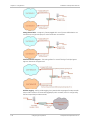
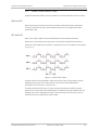
until the best signal is reached. See the following figure for audible signal variations.
Figure 2-7. Beep Sequence for Antenna Alignment
Note
Three beeps and a pause is 'best signal so far'.
Two beeps and a pause is 'signal quality increased'.
One beep and pause is 'no change in signal'.
Long beep and short pause is 'signal quality decreased'.
One beep and a long pause is 'no air link'.
Any other signal does not relate to antenna alignment.
Intrepid and Intrepid Ultra Ver. 2.6
Connecting and Aligning ODUs / Antennas
2-13
Chapter 2 Installation and Setup
Installation and Operation Manual
10. Secure the site A antenna to the pole/wall.
11. Repeat steps 4 to 8 for site B.
2.10
Working with the Link Manager Application
The Intrepid Series Radio management application is distributed on CD-ROM as an
executable file. System-specific PC resources required by the application are detailed in
Table 2-3.
Table 2-3. PC Requirements for the Link manager
Windows 2000
Windows XP Pro
Windows Vista/Windows 7
RAM
128 MB
512 MB
1 GB
Processor
P III
P IV
P IV Dual Core
Disk: 1 GB free hard disk space
Network: 10/100BaseT NIC
Graphics: Card and monitor that support 1024 768 screen resolution
with 16 bit color
Microsoft Explorer 5.01 or later.
Installing the Link Manager
To install the Link Manager:
1.
Insert the CD-ROM into your CD-ROM drive.
The installation starts automatically.
2.
Follow the on-screen instructions of the installation wizard to complete setup of the
Link Manager program in the desired location.
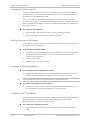
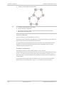
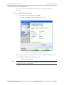
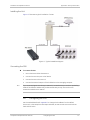
Starting the Link Manager
To start the Link Manager:
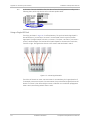
1.
Connect the managing computer to one of the two LAN ports of the IDUE as shown
below.
Figure 2-8. LAN Ports on the Front Panel of the IDUE
If you are not using a direct connection as above, ensure that you have IDU to managing
computer connectivity (e.g. through a LAN).
2-14
Working with the Link Manager Application
GE MDS Intrepid and Intrepid Ultra Ver. 2.6
Installation and Operation Manual
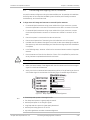
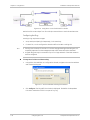
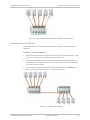
2.
Chapter 2 Installation and Setup
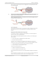
Check that you have connectivity to the ODU. You can do this by opening up a
command line session (Start>Run and then type, cmd). At the command prompt, type:
ping 10.0.0.120
You should receive a reply from Intrepid Series Radio.
Figure 2-9. Pinging an Uninstalled and Unconfigured Link
Any other response from ping means that the ODU is not responding. Check your Ethernet
connection and that both the IDU and ODU are switched on and then try again.
3.
Dismiss the command line session.
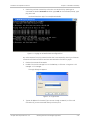
4.
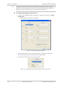
Double-click the Link manager icon on the desktop, or click Start > Programs > Link
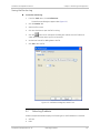
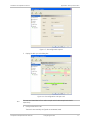
manager > Link manager.
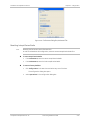
The Login dialog box appears.
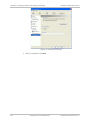
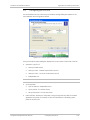
Figure 2-10. Login Screen
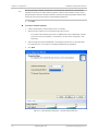
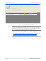
5.
Type an IP address for the ODU (if you connect through a network), or click Local
Connection (if you are connected directly to the IDU port).
Intrepid and Intrepid Ultra Ver. 2.6
Working with the Link Manager Application
2-15
Chapter 2 Installation and Setup
Caution
Installation and Operation Manual
If you log in on Local Connection, but your physical connection is not local (i.e. anything
other than a direct connection between the managing computer and the IDU), then any
configuration you carry out may affect other links in the network.
If you log in via an over-the-air IP address, you will receive a warning. If you reset the
site to which you are connected to factory settings, you can lock yourself out of the link.
Network login (IP address to the ODU) is recommended.
Note
If you log on using Local Connection through a PoE device, you will need to connect it to
the managing computer using a crossed Ethernet cable.
The default IP address for the ODU is 10.0.0.120. The subnet mask is 255.0.0.0. The actual
IP address is defined during link configuration (see Chapter 4).
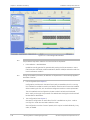
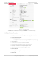
6.
Select your user type:
An Observer has read-only access to the link. An Observer can monitor the link,
generate reports, but may not change any link parameters.
An Operator can install and configure the link.
An Installer can, in addition to functioning as an Operator, also change the
operating band. The latter function requires familiarity with local regulations.
Table 2-4. User Types
User Type
Default Password
Function
Community
Community String
Observer
admin
Monitoring
Read-Only
public
Operator
admin
Installation,
configuration
Read-Write
netman
Installer
wireless
Operator plus set
band
Read-Write
netman
Note
Change default passwords as soon as possible.
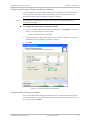
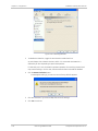
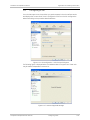
7.
Note
2-16
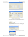
If you are a user with Read-Write permission, click Options to enter the Community
options.
If you are using the system for the first time, leave the default Community
passwords, netman for read-write, and public for read-only.
If Community values were previously defined, enter them under Community in the
Read-Only or Read-Write boxes.
If you are a user with read-only permission, click the Read Only Mode check box.
Intrepid Series Radio is protected with Community passwords. A user may be defined with
read-only permission or with read-write permission (see Chapter 4 for more details).
Working with the Link Manager Application
GE MDS Intrepid and Intrepid Ultra Ver. 2.6
Installation and Operation Manual
Chapter 2 Installation and Setup
Figure 2-11. Login Screen with Community Options Visible
Login Errors
This section describes problems that may occur during login.
Unsupported Device
Attempting to connect to an unsupported device on an otherwise valid IP address (for
example, a LAN printer) results in the following error message:
Figure 2-12. Unsupported Device Message
Incorrect IP Address
If the IP address chosen is invalid or the link is unreachable, the following error message is
displayed:
Intrepid and Intrepid Ultra Ver. 2.6
Working with the Link Manager Application
2-17
Chapter 2 Installation and Setup
Installation and Operation Manual
Figure 2-13. Unreachable Device Message
In both of the above situations, if you click No, you will see a warning graphic
alongside the IP Address field.
Incorrect Password
If you type an incorrect password in the Login screen, a warning graphic
alongside the password field.
is displayed
Invalid Read/Write Community String
This results in the following message:
Figure 2-14. Invalid Community String Message
Logging in to the Over-the-Air Site
You can log in to the over-the-air site of an established link (Site B in our example).
However, you will be first offered the following caution:
Figure 2-15. Logging in to an Over-the-Air Site
2-18
Working with the Link Manager Application
GE MDS Intrepid and Intrepid Ultra Ver. 2.6
Installation and Operation Manual
Chapter 2 Installation and Setup
Continuing without an IP Address
The Link manager provides limited “offline” functionality when there is no accessible
IDU/ODU. It is primarily for setting managing computer related parameters and running
the Link Budget Calculator.
Changing the Login Password
To change the login password:
1.
From the Tools menu, select Change Password.
The Change Password dialog box appears.
2.
Enter the current password, and the new password.
3.
Click OK to confirm.
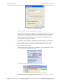
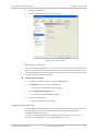
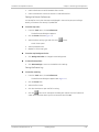
Using Link Manager Spectrum View
Prior to running the link installation wizard may use the Link manager Spectrum View
utility.
The Link Manager Spectrum View utility is an RF survey tool designed to support the link
installation prior to full link service activation. The tool provides comprehensive and clear
spectral measurement information enabling easier, faster and better quality installations.
You can view real-time spectrum information, save the spectral information and view
retrieved spectral information from historic spectrum scans.
The spectrum measurement and estimation algorithms are designed to show accurate
information while accommodating with variations in frequency, temperature and
interference power while overcoming anomalies that tend to occur in high interference
environments.
Note
Spectrum view information is supported in GE MDS MIB and can be used by external
Network Management applications.
The Spectrum View information is logged as part of the diagnostics information to
improve link and system diagnostics and remote support. It can be retrieved from the
Link manager menu using Help >Get Diagnostic Information.
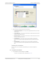
To launch the Spectrum View utility:
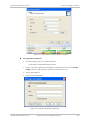
From the Link manager main window, select Tools > Spectrum View.
The main Spectrum View window is displayed.
Intrepid and Intrepid Ultra Ver. 2.6
Working with the Link Manager Application
2-19
Chapter 2 Installation and Setup
Installation and Operation Manual
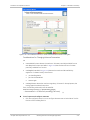
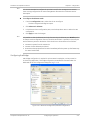
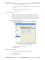
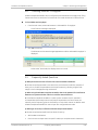
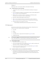
Figure 2-16. Spectrum View Utility before Spectrum Analysis
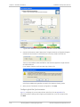
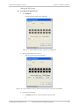
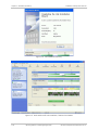
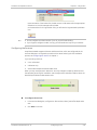
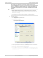
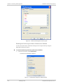
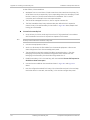
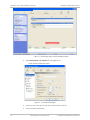
To analyze spectrum:
1.
Click Start Analysis.
A warning message is displayed.
2-20
Working with the Link Manager Application
GE MDS Intrepid and Intrepid Ultra Ver. 2.6
Installation and Operation Manual
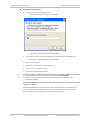
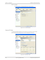
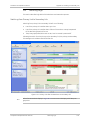
2.
Chapter 2 Installation and Setup
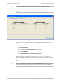
Click Yes to continue.
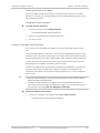
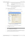
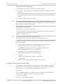
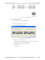
The managing site analysis results are displayed in a few seconds.
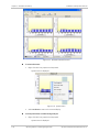
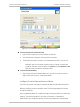
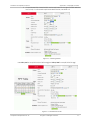
Figure 2-17. Spectrum Analysis Results for Managing Site (Site A)
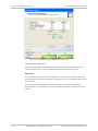
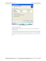
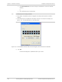
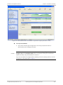
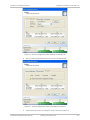
The over-the-air site spectrum analysis results are displayed several seconds
later.
Figure 2-18. Spectrum Analysis Results for Over-the Air Site (Site B)
Intrepid and Intrepid Ultra Ver. 2.6
Working with the Link Manager Application
2-21
Chapter 2 Installation and Setup
Installation and Operation Manual
The analysis complete when the Start Analysis button reverts to green. It never runs for
longer than ten minutes and you may stop it any time by clicking the red Stop Analysis
button.
The results for the over-the-air site are displayed after the link is re-established regardless
whether the analysis completes by itself or is stopped.
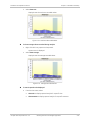
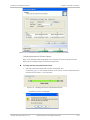
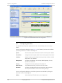
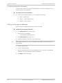
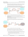
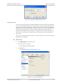
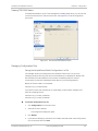
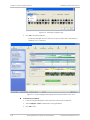
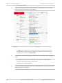
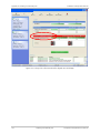
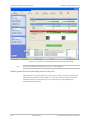
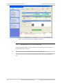
Display Information
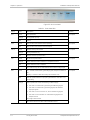
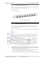
Figure 2-19 explains the Spectrum View window elements.
Figure 2-19. Spectrum View Window Elements
The Spectrum View provides clear information including:
2-22
Spectral measurement for each of the 4 receivers that make an Intrepid Series Radio
link (two sites x two antennas per site)
Spectral power measurements in 5 MHz channel granularity
Current, average and maximum power per channel
Indication of:
Channels free from radars
Channels with radars detected
Barred channels (for DFS bands)
Indication of scanned and unscanned channels
Indication of channels selected for ACS
Notation of the current operational channel of the Intrepid Series Radio link
Working with the Link Manager Application
GE MDS Intrepid and Intrepid Ultra Ver. 2.6
Installation and Operation Manual
Chapter 2 Installation and Setup
Time stamp of the last spectrum scan
Further, it supports zoom capability, selective view of antennas and sites constituting
the link and selectable detail level.
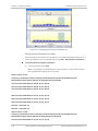
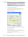
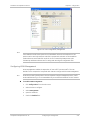
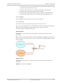
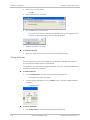
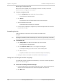
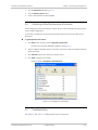
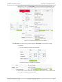
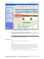
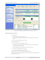
Changing the Display
Moving the mouse anywhere over one the display areas changes it to a cross hair. The
mouse may then be used to select an area for zooming, or to enable a right-click System
menu.
Figure 2-20. Mouse Pointer Active for Zooming
To zoom on specific channels:
1.
Press the right mouse button down.
2.
Select a rectangle on a spectrum view display above the channels in interest.
Figure 2-21. Selecting an Area of Interest to Zoom
3.
Release the right mouse button.
The channels below the selected area become zoomed.
Intrepid and Intrepid Ultra Ver. 2.6
Working with the Link Manager Application
2-23
Chapter 2 Installation and Setup
Installation and Operation Manual
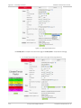
Figure 2-22. Selected Channels Zoomed
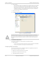
To reverse the zoom:
1.
Right-click within any Spectrum View panels.
System menu is displayed.
Figure 2-23. System Menu
2.
Select Un-Zoom to return to the normal display.
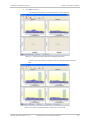
To show peak values recorded during analysis:
1.
Right-click within any Spectrum View panels.
System menu is displayed.
2-24
Working with the Link Manager Application
GE MDS Intrepid and Intrepid Ultra Ver. 2.6
Installation and Operation Manual
2.
Chapter 2 Installation and Setup
Select Show Max.
Display shows the maximum recorded values.
Figure 2-24. Maximum Recorded Values
To show average values recorded during analysis:
1.
Right-click within any Spectrum View panels.
System menu is displayed.
2.
Select Show Average.
Display shows the average recorded values.
Figure 2-25. Average Recorded Values
To restrict panels to be displayed:
From the View menu, select:
Show Site to display spectral analysis for a specific site.
Show Antenna to display spectral analysis for a specific antenna.
Intrepid and Intrepid Ultra Ver. 2.6
Working with the Link Manager Application
2-25
Chapter 2 Installation and Setup
Installation and Operation Manual
Figure 2-26. Displaying Spectral View for Antenna A only
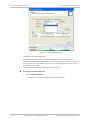
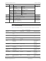
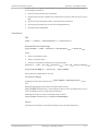
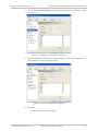
Saving Spectrum Analysis Information
Spectrum analysis information can be saved in a CSV (comma separated values) text file. It
can be retrieved from the Link manager menu using Help > Get Diagnostic Information.
To save the spectrum analysis information:
From the file menu, select Save.
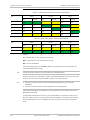
Below is an example of a saved spectrum view information. It can be later imported
into a spreadsheet program, such as MS Excel.
Spectrum View - Site: A
Frequency,Is Scanned,Last Scan Timestamp,Last NF-AntennaA,Last NF-AntennaB,Average NFAntennaA,Average NF-Anten-naB,Max NF-AntennaA,Max NF-AntennaB
5735,True,30/11/2009 08:20:52,-89,-90,-90,-91,-89,-90,
5740,True,30/11/2009 08:20:52,-89,-90,-90,-91,-89,-90,
5745,True,30/11/2009 08:20:52,-89,-90,-90,-91,-89,-90,
...
5830,True,30/11/2009 08:20:52,-92,-94,-93,-94,-92,-93,
5835,True,30/11/2009 08:20:52,-92,-94,-93,-95,-92,-94,
5840,True,30/11/2009 08:20:52,-92,-94,-93,-95,-92,-94,
Rx Power - AntennaA: -55
Rx Power - AntennaB: -55
Spectrum View - Site: B
Frequency,Is Scanned,Last Scan Timestamp,Last NF-AntennaA,Last NF-AntennaB,Average NFAntennaA,Average NF-Anten-naB,Max NF-AntennaA,Max NF-AntennaB
5735,True,30/11/2009 08:20:53,-91,-90,-92,-91,-91,-90,
2-26
Working with the Link Manager Application
GE MDS Intrepid and Intrepid Ultra Ver. 2.6
Installation and Operation Manual
Chapter 2 Installation and Setup
5740,True,30/11/2009 08:20:53,-90,-89,-91,-90,-90,-89,
5745,True,30/11/2009 08:20:53,-90,-89,-91,-90,-90,-89,
...
5830,True,30/11/2009 08:20:53,-93,-94,-94,-94,-93,-93,
5835,True,30/11/2009 08:20:53,-93,-94,-94,-95,-93,-94,
5840,True,30/11/2009 08:20:53,-93,-94,-94,-95,-93,-94,
Rx Power - AntennaA: -57
Rx Power - AntennaB: -55
The column headings are wrapped around. The table values in dBm are noise-floor (NF)
relative. The CSV file imports easily into most spreadsheet programs, such as MS Excel.
Note
Spectrum view information is supported in the product MIB and can be used by external
network management applications.
Installing the Link
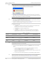
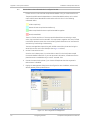
After the login the main Link Manager window is displayed.
Note
For the purposes of illustration, the following IP addresses will be used:
NMS – 192.168.1.100
The log-on ODU – 192.168.1.101
Over-the-air ODU – 192.168.1.102.
The subnet mask for both sites is 255.255.255.0 and no default gateway is defined.
If the login is successful, Intrepid Series Radio displays the opening window.
Intrepid and Intrepid Ultra Ver. 2.6
Working with the Link Manager Application
2-27
Chapter 2 Installation and Setup
Installation and Operation Manual
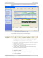
Figure 2-27. Link manager Main Window
Note
The procedure required to make the link functional has three phases:
1.
Link Installation – detailed below.
Installation actually gets the link operational by setting the link parameters. It uses a
fixed channel at the lowest possible modulation, BPSK at 6.5Mbps and works under the
harsh interference condition.
Note
During the installation procedure, the definition of all parameters is automatically applied to
both sides of the link.
2.
Link Configuration (see Chapter 4)
Configuration provides much the same functionality as Installation, but for a running
link. A fallback to Installation mode is provided for situations which cannot be handled
without resetting the link, such as antenna realignment and IDU or ODU replacement.
The Link Installation and Configuration phases are both carried out with Wizards,
which “walk you through” the processes. The Wizards are visually quite similar and will
be described in detail below.
3.
Site Configuration (see Chapter 4)
Site specific configuration for each side of the link is available at any time - under a
running link or under the restricted Installation mode.
Site Configuration consists of a set of panels, which may be invoked individually in any
order, as needed.
2-28
Working with the Link Manager Application
GE MDS Intrepid and Intrepid Ultra Ver. 2.6
Installation and Operation Manual
Chapter 2 Installation and Setup
An installed and configured link can be returned to installation mode for re-installation and
configuration from last settings or from factory settings.
Note
Reversion to installation mode requires a complete break in the link service
Configuration mode may vary the service throughput and quality, but without a service
break.
Link Installation Overview
Link installation procedure includes the following steps:
1.
Initiating the link installation wizard
2.
Defining system parameters
3.
Selecting a channel
4.
Defining transmit power and system settings
5.
Viewing configuration summary and completing the wizard.
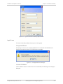
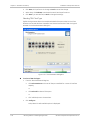
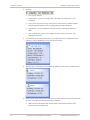
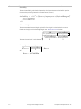
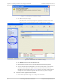
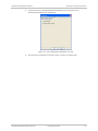
Initiating the Link Installation Wizard
To initiate the link installation wizard:
1.
In the tool bar of the Link manager main window, click the Link Installation button.
The Installation Wizard opens.
Note
The Link Installation button is only accessible if antennas are properly aligned.
2.
Click Next to proceed with the installation procedure.
Figure 2-28. Link Installation Wizard, Opening Screen
Intrepid and Intrepid Ultra Ver. 2.6
Working with the Link Manager Application
2-29
Chapter 2 Installation and Setup
Installation and Operation Manual
The bottom data area reproduces the corresponding data from the main window, which is
obscured by the above panel.
Note
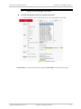
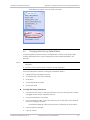
Defining System Parameters
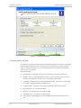
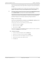
The System dialog box allows configuration of the general link and site parameters.
To define the system parameters:
1.
Note
From the System dialog box, configure the following parameters:
Enter a Link ID. The Link ID must be identical for both ODUs in the link,
otherwise they will not communicate. The Link ID must include at least eight
alphanumeric characters. Up to 24 characters are allowed. You should use a Link
ID composed of both alphabetic and numeric characters.
Link Name for the link identification. The default name is “Link”. It is recommended
to change the default name.
Site 1 and Site 2 names. The default names are both “Location”. It is
recommended to change the default names. Throughout this manual, A for Site 1
and B for Site 2 are used.
Link password (optional). Default password is wireless-bridge.
The link password is associated with the link, it does not have anything to do with the Link
manager login password.
If an incorrect password is entered, a link is established but configuration cannot be
performed and no services are available. A new link password may be obtained from RAD.
You can also acquire an alternative password as explained below.
2.
Click Next to continue.
Intrepid Series Radio starts evaluating the link at a default rate of 6.5 Mbps.
2-30
Working with the Link Manager Application
GE MDS Intrepid and Intrepid Ultra Ver. 2.6
Installation and Operation Manual
Chapter 2 Installation and Setup
Figure 2-29. Link Installation Wizard, System Dialog Box
To change the link password:
1.
Click the Change button in the System dialog box.
The Change Link Password dialog box opens.
2.
Enter the current link password. (The default link password for a new ODU is wirelessbridge). Select the Hide characters check box for maximum security.
3.
Enter a new password.
4.
Confirm the new password.
Figure 2-30. Change Link Password Dialog Box
Intrepid and Intrepid Ultra Ver. 2.6
Working with the Link Manager Application
2-31
Chapter 2 Installation and Setup
Installation and Operation Manual
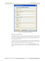
To acquire a new password:
1.
Click the Forgotten Link Password button.
Link Password Recovery dialog box is displayed.
Figure 2-31. Link Password Recovery Dialog Box
2.
Follow the instructions to use the Alternative Link Password, and click OK to finish.
The Change Link Password dialog box is displayed.
Note
3.
Enter a new password.
4.
Retype the new password in the Confirm field.
5.
Confirm the link password change.
6.
Click OK to complete the procedure.
Restoring Factory Defaults returns the Link Password to wireless-bridge.
If the link is inactive, then the link password may also be changed from the Site
Configuration dialogs.
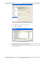
Selecting Channels
Intrepid Series Radio features an Automatic Channel Selection (ACS). In the event of sync
loss, ACS chooses the first available channel in a list of monitored channels. A channel
switch takes place sufficiently fast as to ensure no loss of service.
2-32
Working with the Link Manager Application
GE MDS Intrepid and Intrepid Ultra Ver. 2.6
Installation and Operation Manual
Chapter 2 Installation and Setup
Figure 2-32. Link Installation Wizard, Channel Settings Dialog Box
To select channels to be used by the link:
1.
Select the main frequency from the Installation Channel box.
2.
Click the check box if Automatic Channel Selection is required.
3.
The Available Channels List contains all of the allowable channels for the link. Check
the channels that can be automatically selected.
Selecting a new channel causes the system quality to change. The Quality bar
provides an indication of the link quality from No serv(ice) (red) to Ethernet + TDM
(green) as shown in the bottom of the figure above.
To select channel bandwidth:
1.
Select the required channel bandwidth (10, 20 or 40 MHz) for Intrepid Ultra Series
Radio, and 10 and 20 Mbps for Intrepid Series Radio.
2.
Click Next.
Configuring Transmit Power and Antenna Settings
The choice of Tx power, antenna gain and cable loss determines the EIRP and is affected
by such considerations as radio limitations and regulatory restrictions.
Before proceeding to antenna installation details, the following background information
should be considered:
Each Intrepid Series Radio ODU is made of two radio transceivers (radios). The radios make
use of algorithms that utilize both polarization and space diversity resulting in enhanced
capacity, range and link availability. The number of antennas (i.e. radios) used is
determined by user configuration and by automatic system decisions, explained below.
Intrepid and Intrepid Ultra Ver. 2.6
Working with the Link Manager Application
2-33
Chapter 2 Installation and Setup
Installation and Operation Manual
Figure 2-33. Transmission Power and Antenna Parameters
Dual Antennas at Both Sites
When using dual, single-polarized antennas at both sites (single bipolar antenna or two
monopolar antennas) you can choose between MIMO Mode and Diversity mode.
MIMO Mode
With MIMO the system doubles the link capacity. At the same time, it keeps the same rate
and modulation per radio as was used with single antenna, thus increasing capacity, range
and availability.
For example with a dual antenna Intrepid Series Radio can transmit at modulation of
64 QAM and FEC of 5/6 and get an air rate of 130 Mbps, compared to 65 Mbps with single
antenna.
2-34
Working with the Link Manager Application
GE MDS Intrepid and Intrepid Ultra Ver. 2.6
Installation and Operation Manual
Chapter 2 Installation and Setup
To work in this mode, each antenna port must be connected to an antenna, the RSS level in
both receivers should be balanced and a minimal separation between the antennas must
be maintained. (For example, by using dual polarization antennas a cross polarization
separation is attained).
Upon selecting Antenna Type as Dual, Intrepid Series Radio automatically selects MIMO
mode and doubles the air rates. Link manager indicates a case of unbalanced RSS
between the two antennas.
Diversity Mode
Diversity Mode uses two antennas to improve the quality and reliability of the link. Often,
there is not a clear line-of-sight (LOS) between transmitter and receiver. Instead the signal
is reflected along multiple paths before finally being received.
Each such “bounce” can introduce phase shifts, time delays, attenuations, and even
distortions that can destructively interfere with one another at the aperture of the
receiving antenna. Antenna diversity is especially effective at mitigating these multipath
situations.
This is because multiple antennas afford a receiver several recordings of the same signal.
Each antenna will be exposed to a different interference environment. Thus, if one antenna
is undergoing a deep fade, it is likely that another has a sufficient signal. Collectively such a
system can provide a robust link.
Antenna diversity requires antenna separation which is possible by using a
dual-polarization antenna or by two spatially separated antennas.
Use Diversity instead of MIMO in the following situations:
When the system cannot operate in MIMO mode
When one of the receivers has high interference compared to the second receiver (i.e.
the system is “unbalanced”)
When you achieve higher capacity in Diversity mode than in MIMO mode
When high robustness is of importance and the capacity of Diversity mode is sufficient
Single Antennas at Both Sites
By selecting a single antenna at both sites the ODUs operate with a single radio that is
connected to the ANT 1 connector. The second radio is automatically shut down.
Single and Dual Antennas
In this mode one of the sites uses the ODU with a single antenna while the other site uses
the ODU with a dual antenna.
The advantages in this mode in comparison to using a single antenna in both sites are
doubled total Tx power and additional polarization and/or space diversity.
Intrepid Series Radio automatically switches to this mode if one of the ODUs is connected to
a dual antenna or if the RSS at one of the ODU receivers is below minimal level.
The air rates used in this mode are same as when using single antennas in both sites.
Intrepid and Intrepid Ultra Ver. 2.6
Working with the Link Manager Application
2-35
Chapter 2 Installation and Setup
Installation and Operation Manual
Table 2-5. MIMO and Diversity Modes
Number of Antennas
Site A
Mode
Graphic Indication
Max Full Duplex Capacity
Site B
MIMO
50 Mbps
Diversity
25 Mbps
2
2
2
1
25 Mbps
1
2
25 Mbps
1
1
25 Mbps
The rates used by Intrepid Series Radio are shown below:
Table 2-6. Transmission Rates
2-36
Radio
Modulation
FEC
Air-Rate
[Mbps]
Single
BPSK
1/2
6.5
Single
QPSK
1/2
13
Single
QPSK
3/4
19.5
Single
16QAM
1/2
26
Single
16QAM
3/4
39
Single
64QAM
2/3
52
Single
64QAM
3/4
58.5
Single
64QAM
5/6
65
Dual
BPSK
1/2
13
Dual
QPSK
1/2
26
Dual
QPSK
3/4
39
Dual
16QAM
1/2
52
Dual
16QAM
3/4
78
Dual
64QAM
2/3
104
Dual
64QAM
3/4
117
Dual
64QAM
5/6
130
Working with the Link Manager Application
GE MDS Intrepid and Intrepid Ultra Ver. 2.6
Installation and Operation Manual
Chapter 2 Installation and Setup
.
Figure 2-34. Link Installation Wizard, Tx Power and Antenna Parameters Dialog Box
Considerations for Changing Antenna Parameters
Let:
maxAvailableTx Power denote the maximum Tx Power practically available from an
ODU (Required Tx Power per Radio in Figure 2-35) denote the maximum Tx Power
practically available from an ODU.
maxRegEIRP (Max EIRP in Figure 2-35) denote the maximum EIRP available by
regulation. It is determined by three factors:
per band/regulation
per channel bandwidth
antenna gain
maxRegTxPower denote the maximum regulatory Tx Power for the equipment, also
having regard the above three points.
Then, the following relationship must be satisfied:
maxAllowedTxPower min(maxRegEIRP
– AntennaGain + CableLoss maxRegTxPower)
(*)
To set Tx power and configure antennas:
1.
Click the Configure buttons in turn to configure the antennas on both sides of the link.
Each one offers a dialog like this:
Intrepid and Intrepid Ultra Ver. 2.6
Working with the Link Manager Application
2-37
Chapter 2 Installation and Setup
Installation and Operation Manual
Figure 2-35. Antenna Configuration Dialog with Opened Type Selection
2.
Choose the antenna type and required transmission (Tx) power for the first site and
click OK. Repeat the process for the second site.
The Tx power (per radio) indicates the power of each radio inside the ODU and is used
for Link Budget Calculations. The Tx power (System) shows the total transmission
power of the ODU and is used to calculate the EIRP according to regulations.
Note
To see the relationship between Tx Power (radio) and TX Power (system), note that
dBm = 10 log 10milliWatt
radios) then dBm will increase by
3.
so that if you double the power in milliWatts (for two
10 log 102 3
.
Set the Antenna Gain and Cable Loss. If do this you will receive a warning message:
Figure 2-36. Antenna Parameters Change Warning
2-38
Working with the Link Manager Application
GE MDS Intrepid and Intrepid Ultra Ver. 2.6
Installation and Operation Manual
Note
Chapter 2 Installation and Setup
The Max EIRP level will be automatically set according to the selected band and
regulation.
The EIRP level is the sum of the System Tx power and the Antenna Gain minus the Cable
Loss.
If inequality (*) above is violated, then the following warning window is displayed:
Figure 2-37. Tx Power Limits
The precise relationship between the items in inequality (*) and the window of Figure 2-35
is follows:
Required Tx Power (per radio) will be adjusted down to the lesser of the value entered
and maxAllowedTxPower
TxPower (system)is maxAllowedTxPower + 3 (for 2 radios)
Max EIRP is maxRegEIRP.
EIRP is maxAllowedTx Power + Antenna Gain - Cable Loss
The table in Figure 2-37 only shows rates where the maximum Tx Power is the limitation,
rather than regulations. When you close the window of Figure 2-37, the change you
requested will not be honored, and you will need to try again. When you close the window
of Figure 2-37, the change you requested will not be honored, and you will need to try
again.
Note
Since our demonstration link is entirely indoors, we have reduced Tx Power to 5 dBm to
obtain a realistic RSS. Although this is much too low for field use, the method is general.
Intrepid and Intrepid Ultra Ver. 2.6
Working with the Link Manager Application
2-39
Chapter 2 Installation and Setup
Installation and Operation Manual
Figure 2-38. Antennas Configured for Two Dual and Tx Power 5 dBm
4.
Choose Dual Antenna mode if appropriate. The green Antenna Configuration diagram
indicates the active state. For dual antennas in Diversity mode it looks like this:
There are intermediate modes available for dual antennas opposite a single antenna
as explained above.
If you make a change you will see a warning similar to this:
A similarly worded warning applies to a switch from MIMO to Diversity mode.
5.
When you are finished with Tx Power configuration, click Next.
Configuring Hub Site Synchronization
Figure 2-39 displays the current status of each side of the link. See Appendix G for
instructions about installing and configuring collocated links. If you do not require HSS,
click Next.
2-40
Working with the Link Manager Application
GE MDS Intrepid and Intrepid Ultra Ver. 2.6
Installation and Operation Manual
Chapter 2 Installation and Setup
Figure 2-39. HSS Settings
Configuring the Services
Intrepid Series Radio supports Ethernet and TDM services, which are configured via the
Services dialog box.
For Intrepid Ultra Series Radio models, allocate asymmetric Ethernet capacity by changing
the transmission ratio between the sites, see Configuring Asymmetric Ethernet Capacity below.
For Intrepid Series Radio models, and collocated links, proceed to Configuring TDM Services
below.
Intrepid and Intrepid Ultra Ver. 2.6
Working with the Link Manager Application
2-41
Chapter 2 Installation and Setup
Installation and Operation Manual
Figure 2-40. Link Installation Wizard, Services Dialog Box for Intrepid Ultra Series Radio
Figure 2-41. Link Installation Wizard, Services Dialog Box for Intrepid Series Radio Collocated as a Client
2-42
Working with the Link Manager Application
GE MDS Intrepid and Intrepid Ultra Ver. 2.6
Installation and Operation Manual
Chapter 2 Installation and Setup
Figure 2-42. Link Installation Wizard, Services Dialog Box for Intrepid Series Radio
Configuring Asymmetric Ethernet Capacity
Ratio of the upload and download speed on the Ethernet link of the Intrepid Ultra Series
Radio can be changed using the Transmission Ratio slider.
To change the Ethernet uplink/downlink ratio:
1.
Slide the Transmission Ratio slider to select the required ratio.
For example, Figure 2-43 illustrates allocation of the 70% of the link to the downstream
Ethernet traffic and 30% – to the upstream.
Figure 2-43. Changing the Ethernet Uplink/Downlink Ratio
The following caution is displayed:
Intrepid and Intrepid Ultra Ver. 2.6
Working with the Link Manager Application
2-43
Chapter 2 Installation and Setup
Caution
Installation and Operation Manual
If you have active collocated links, or if you are uncertain of whether collocated links
provide TDM services, do not use this option now. You can do it at a less disruptive time
using the Link Configuration (see Chapter 4).
2.
Click Yes to continue.
3.
If you are not using TDM services, click Next to complete link installation.
Limitations on the Use of Asymmetric Allocation
For non-collocated links, capacity allocation between uplink and downlink traffic is
determined automatically according to actual Ethernet traffic and air interface conditions.
Your manual allocation using this feature “cuts in” during congestion.
Asymmetric Allocation and Collocation
The use of Asymmetric Allocation is limited where the link is collocated.
Figure 2-44. Services and Rates - Intrepid Series Radio Master and Clients
The yellow areas should not be used. Using these areas, you may lose the collocated link
with the longest distance between sites.
Asymmetric Allocation and TDM
You cannot use this feature when TDM services are used. Selection of TDM ports as in the
next section resets the Ethernet balance to 50% in each direction and the green slider does
not appear in subsequent installation or configuration runs.
Cancelling TDM port use makes the allocation bar reappear, re-enabling asymmetric
Ethernet traffic allocation.
2-44
Working with the Link Manager Application
GE MDS Intrepid and Intrepid Ultra Ver. 2.6
Installation and Operation Manual
Chapter 2 Installation and Setup
Configuring TDM Services
To configure the TDM services:
1.
Click Configure.
The TDM Services dialog box is displayed.
Figure 2-45. Link Installation Wizard, TDM Services Dialog Box
2.
Select a TDM service type: E1 or T1.
TDM Ports section becomes available.
Figure 2-46. Link Installation Wizard, TDM Services Dialog Box, TDM Ports are Available
3.
Select active TDM ports:
Use Select spin box to choose consecutive service ports
or
Intrepid and Intrepid Ultra Ver. 2.6
Working with the Link Manager Application
2-45
Chapter 2 Installation and Setup
Installation and Operation Manual
Click Select Maximum to choose all TDM port available for current air interface
capacity
or
Note
Click individual ports to choose them.
Ethernet service is always selected.
The number of available services is changed in accordance with actual air interface
capacity.
The selected ports are enabled for both sides of the link. You cannot for example, use
ports 1, 3, 5, 7 on one side and 2, 4, 6, 8 on the other.
Figure 2-47. Link Installation Wizard, TDM Services Dialog Box, Seven TDM Ports are Selected
4.
Click OK.
The Services dialog box is updated to reflect your choice:
2-46
Working with the Link Manager Application
GE MDS Intrepid and Intrepid Ultra Ver. 2.6
Installation and Operation Manual
Chapter 2 Installation and Setup
Figure 2-48. Link Installation Wizard, Services Dialog Box, Services are Selected
Selecting Modulation Rate
You can choose a specific modulation rate or use adaptive rate to dynamically adapt the
air interface rate by changing both the signal modulation and coding.
To select modulation rate:
1.
In the Services dialog box, choose Adaptive or one of the available rates.
2.
Click Evaluate to continue or click the TDM Jitter Buffer tab to set the TDM jitter buffer
size.
Intrepid and Intrepid Ultra Ver. 2.6
Working with the Link Manager Application
2-47
Chapter 2 Installation and Setup
Installation and Operation Manual
Figure 2-49. Selecting Modulation Rate
Configuring TDM Jitter Buffer Size
The receiver jitter buffer for each site can be enlarged, thereby increasing system
resistance to interference (the larger the jitter buffer, the longer the interference period
that the system overcomes without TDM errors). You can also decrease the jitter buffer to
decrease the system delay.
The jitter buffer can be configured between 2.0 and 16.0 ms.
To configure TDM jitter buffer size:
1.
Click the TDM Jitter Buffer tab.
The TDM Jitter Buffer Configuration dialog box is displayed.
2-48
Working with the Link Manager Application
GE MDS Intrepid and Intrepid Ultra Ver. 2.6
Installation and Operation Manual
Chapter 2 Installation and Setup
Figure 2-50. TDM Jitter Buffer Configuration Dialog Box
2.
Set the desired jitter buffer depth value for both sites.
3.
Click Evaluate to check the TBFR (TDM Block Failure Ratio).
The TBFR evaluation bar is displayed at the bottom of the screen.
Figure 2-51. TDM Jitter Buffer Configuration Dialog Box, TBFR Evaluation Bar Displayed
Intrepid and Intrepid Ultra Ver. 2.6
Working with the Link Manager Application
2-49
Chapter 2 Installation and Setup
Installation and Operation Manual
4.
Click Next, which performs the change or Back to cancel the change.
5.
When done, click Evaluate to evaluate the overall service performance.
6.
Click Next if you are satisfied, or Back to change the settings.
Selecting TDM Clock Type
Flexible timing scheme allows the Intrepid Series Radio TDM ports to derive clock from
different sources and distribute it between local site and remote sites. TDM clock type is
selected via the TDM Parameters dialog box:
Figure 2-52. TDM Parameters Dialog Box
To select a TDM clock type:
1.
From the TDM Parameters dialog box,
Click Select Maximum to choose all TDM port available for current air interface
capacity
or
Click Select All to select all TDM ports
or
2.
Click individual ports to choose them.
Click Configure.
A drop-down list with available options is displayed.
2-50
Working with the Link Manager Application
GE MDS Intrepid and Intrepid Ultra Ver. 2.6
Installation and Operation Manual
Chapter 2 Installation and Setup
Figure 2-53. TDM Parameters Dialog Box, Clock Configuration in Progress
3.
Select a TDM port clock type to be one of the following:
Transparent/Transparent – The clock at Site A regenerates the clock from Site B
and vice versa.
Loop time/Recover – The Site A port receive clock is used as the transmit clock for
that port on both sides of the link.
Recover/Loop time – The Site B port receive clock is used as the transmit clock for
that port on both sides of the link.
Internal/Recover – The Site A port uses its internal oscillator to generate its
transmit clock while the Site B port regenerates the clock received at the Site A
port.
Recover/Internal – The Site B port uses its internal oscillator to generate its
transmit clock while the Site A port regenerates the clock received at the Site B
port.
Completing the Link Installation
The last screen of the link installation wizards allows you to view the configuration
summary.
To complete the link installation:
In the Installation Summary dialog box, click Done.
The main Link manager window is displayed (Figure 2-55).
Intrepid and Intrepid Ultra Ver. 2.6
Working with the Link Manager Application
2-51
Chapter 2 Installation and Setup
Installation and Operation Manual
Figure 2-54. Link Installation Summary
Figure 2-55. Main Window after Link Installation, TDM Services Enabled
2-52
Working with the Link Manager Application
GE MDS Intrepid and Intrepid Ultra Ver. 2.6
Installation and Operation Manual
Chapter 2 Installation and Setup
Figure 2-56. Main Window after Link Installation, Asymmetric Capacity Allocation, no HSS
To verify the installation:
Caution
Verify that the Radio Signal Strength (RSS) is according to expected results as
determined by the Link Budget Calculator.
Installation mode, as described above, may be re-entered using Configuration | 1
Configure Site A and Installation Mode the Site Configuration dialog. Some Installation
mode functionality may cause a break in link service.
If you can accomplish link changes without breaking the service, always prefer to use Link
Configuration mode, described in Chapter 4.
Intrepid and Intrepid Ultra Ver. 2.6
Working with the Link Manager Application
2-53
Chapter 3
Operation
This section provides the following information for Intrepid Series Radio:
Operating procedures (turning-on and turning-off)
IDU indicators
Normal indications
Default settings
Managing the Intrepid Series Radio.
3.1
Turning On the Unit
To turn on Intrepid Series Radio:
Connect the AC/DC converter to the IDU power connector and to the mains. See
Chapter 2 for full instructions on connecting the power.
The PWR indicator lights up (IDU only) and remains lit as long as the IDU is
receiving power.
Intrepid Series Radio requires no operator attention once installed, with the exception of
occasional monitoring of front panel indicators and statistics data. Intervention is only
required when Intrepid Series Radio must be configured to its operational requirements, or
diagnostic tests are performed.
The front panel of the IDU-S and IDU-C includes a series of LED indicators that show the
operating status of the unit. Figure 3-1 , Figure 3-2, Figure 3-3 show the IDU front panel.
Table 3-1 describes the front panel indicators.
IDUE
LAN
RAD
1
IDU ODU HSS
ODU
SVC AIR I/F
PRIMARY
ALARMS
2
SECONDARY
3
Figure 3-1. Ethernet-only IDU-E Front Panel
LAN
RAD
IDU
1
ODU
HSS
SVC AIR I/F STBY
1
3
5
TRUNKS
7
9
11
13
IDUE
15
ALARMS
ODU
2
3
2
4
6
8
10
12
14
STBY
PRIMARY
SECONDARY
16
Figure 3-2. TDM/Ethernet IDU-E Front Panel
Intrepid and Intrepid Ultra Ver. 2.5
Turning On the Unit
3-1
Chapter 3 Operation
Installation and Operation Manual
Figure 3-3. ID-S Front Panel
Table 3-1. Front Panel LEDs
Name
Color
Description
Location
IDU
Green
IDU operational
Front panel
Orange
During power-up only
Red
Failure
Green
ODU-to-IDU communication link is operating
Red
ODU-to-IDU communication link is disrupted
Green
Wireless link is synchronized
Orange
During installation only
Red
Wireless link lost synchronization
Green
E1/T1 line is synchronized
Orange
Alarm detected on Site B interface or a loopback is active
Red
Alarm detected on Site A interface
ODU
AIR I/F
SVC
Front panel
Front panel
Front panel
Off – Ethernet-only IDU or TDM interface has not been configured yet
HSS
Green
On – The ODU is HSS master, generating signal, and synchronization is
OK
Front panel
Blinking – The ODU is HSS client and synchronization is OK
Red
HSS not operational due to improper signal detection. This ODU is not
transmitting
Orange
HSS is operational. One of the following conditions apply:
This ODU is a master that is generating and detecting signals
This ODU is a master that is generating signals, but detected
improper signals
This ODU is a client “Continue Tx”, but is not detecting signals
This ODU is a client “Disable Tx” and is detecting signals from
multiple sources
All orange cases transmit.
Off –HSS is not active or ODU is disconnected from IDU
3-2
Turning On the Unit
Intrepid and Intrepid Ultra Ver. 2.5
Installation and Operation Manual
Name
Color
Chapter 3 Operation
Description
Location
MHS Mode
Link State
On – Primary
On – Active
Blinking – Secondary
Blinking – Not active
Red
Primary
Not active
Orange
Secondary
Active
Off – Off
MHS is disabled
STBY
Green
Front panel
LINK
Green
On – Good Ethernet link integrity
LAN connector
ACT
Yellow
Blinks according to the Ethernet traffic
LAN connector
Green
On – TDM service is OK
TDM connector
Red
On – AIS or LOS detected
TDM connector
Blinking – Loopback is active
3.2
Default Settings
Table 3-2 lists the default settings of the Intrepid Series Radio configuration parameters.
Table 3-2. Default Settings
Parameter
Description
Default Value
Menu Path
Setting Instructions
Aging Time
MAC address aging
period
300 sec
–
IDU Aging Time
Ethernet Mode
Line speed and duplex
mode negotiation
Auto Detect
Advanced
Configuring Ethernet
Mode
Frequency
Operation channel
frequency
First frequency in
the range
–
Selecting Channels
Link ID
Wireless link
identification
Link
–
Defining System
Parameters
(Chapter 2)
Link Password
Wireless link password
wireless-bridge
–
Defining System
Parameters
Local-public
Local-public
community name
bru1
–
Configuring SNMP
Communities
Manager Logon
Password
Login password of the
Link Manager
admin
–
Changing the Login
Password
ODU IP Address
IP address of the ODU
10.0.0.120
Management
Defining the
Management
Addresses
ODU Mode
Ethernet mode of the
ODU
Hub
Advanced
Configuring Ethernet
Mode
Intrepid and Intrepid Ultra Ver. 2.5
Default Settings
3-3
Chapter 3 Operation
Installation and Operation Manual
Parameter
Description
Default Value
Menu Path
Setting Instructions
Rate
Transmission rate
Adaptive
–
Configuring Service
Parameters
Read-only
Read-only community
name
public
–
Configuring SNMP
Communities
Read-write
Read-write community
name
netman
–
Configuring SNMP
Communities
Remote-public
Remote-public
community name
bru4097
–
Configuring SNMP
Communities
Site 1
Site 1 name
Site
–
Defining System
Parameters
Site 2
Site 2 name
Site
–
Defining System
Parameters
Subnet Mask
IP address of the ODU
255.0.0.0
Management
Defining the
Management
Addresses
Trap destination
IP address of an NMS to
be receiving traps
0.0.0.0
Management
Defining the
Management
Addresses
TDM Jitter Buffer
TDM jitter buffer depth
5.2
Services
Configuring TDM Jitter
Buffer Size
3.3
Configuration and Management Alternatives
The Intrepid Series Radio configuration and monitoring operations are performed using
one of the following tools:
GUI-based management utility (Link Manager)
Telnet.
Most of the Intrepid Series Radio management and operation parameters are set using link
configuration wizard. If necessary, the local and remote unit parameters can be
reconfigured via the Intrepid Series Radio management utility.
Telnet management is performed from a Telnet host using display and set commands.
The capabilities of the two options listed above are identical.
Note
PulseNet NMS management software provides access to the Link Manager via its topology
map.
Working with the Intrepid Series Radio Management Utility
Before starting a management session, make sure that a communication link between
local and remote units exists. The Link Status indication bar in the middle of the Main menu
3-4
Configuration and Management Alternatives
Intrepid and Intrepid Ultra Ver. 2.5
Installation and Operation Manual
Chapter 3 Operation
must be green and the Radio Link - Sync message must appear in the event log (see
Figure 3-4).
Figure 3-4. Main Screen, Wireless Link is Active
The Link Manager main screen consists of the following elements:
Toolbar – includes buttons serving for:
Link Configuration – Changes configuration parameters of an operating wireless
link; assigns text files for storing alarms, statistics and configuration data. This
button is disabled until a link installation has been completed.
Link Installation – Performs preliminary configuration of the system. This button is
disabled after the link is installed.
Site: <Site 1 name> – Opens the Site configuration dialog for Site A. Same as
Configuration > 1 Configure <Site 1 name>
Site: <Site 2 name> – Opens the Site configuration dialog for Site B. Same as
Configuration > 2 Configure <Site 2 name>
Get Diagnostics – Obtain system information
Clear Counters – Disabled
Log off – Closes the current session and logs off Link Manager
Exit – Exits Link Manager.
Intrepid and Intrepid Ultra Ver. 2.5
Configuration and Management Alternatives
3-5
Chapter 3 Operation
Installation and Operation Manual
Menu Bar
File– Log off, and exit
Configuration – use for link configuration, individual site configuration or link
installation
Tools –performance monitoring, active alarms, recent events, software upgrade,
changing band (installation only), changing password and preferences
Maintenance – running loopbacks, clearing counters, resetting Intrepid Series
Radio
Help – displays user manual, link budget calculator, system information, Link
Manager build version.
Link detail pane summarizes information on the radio link (link ID, configured services
frequency, channel bandwidth, current rate and link status)
Site detail pane show basics link site details (IP address, subnet mask, trap destination)
Monitor pane, is the main source of real time information about link performance at both
link sites. It includes the following panes (top to bottom):
3-6
Radio Interface, Received Signal Strength (RSS) in dBm and transmission ratio
(Intrepid Ultra Series Radio only).
Configuration and Management Alternatives
Intrepid and Intrepid Ultra Ver. 2.5
Installation and Operation Manual
Chapter 3 Operation
Ethernet Service:
Estimated Ethernet Throughput: The numbers are the current calculated
throughputs at each site. The colored bars (with numbers) indicate the
maximum possible throughput having regard for air conditions.
Rx and Tx Rates: The Rx and Tx rates are the receive and transmit rates on
the LAN side of each ODU, not the air side. For a balanced link, the Rx and Tx
rates at the LAN side of Site A will match the Tx and Rx rates at the LAN side
of Site B respectively. In all cases, The LAN side Rx rate shown will be the
same as the air side Tx rate for each individual ODU.
Actual Ethernet traffic received and transmitted rates per site, is in Mbps of
Fps, selectable in the panel title bar.
TDM Services, enables you to switch between Accumulative and Current view:
TDM Block Failure Ratio. It is zeroed by the Clear Counters button in the tool
bar.
Error block count is shown immediately above the active TDM channels
display.
The color of the TDM ports reflects their current status:
Green – operational
Red – error: LOS and AIS
Yellow – active loopback
Frequency box: It shows the link frequency. The color of the box indicates the
status:
Green – active link
Red – inactive link
Intrepid and Intrepid Ultra Ver. 2.5
Configuration and Management Alternatives
3-7
Chapter 3 Operation
Installation and Operation Manual
Magenta – authentication or compatibility problem
Brown – severe compatibility problem
Events Log stores alarms generated from both sides of the link
Status Bar displays the current system status:
Connectivity icon showing how the device is connected to the Ethernet.
Over-the-Air connection – using the IP address of the remote unit
Local connection – direct connection to the IDU without using an IP address
Network connection - through a LAN
ODU is unreachable
Encryption icon showing if the link is encrypted:
Encrypted link
Unencrypted link (lock open)
Link Password Validation failed. The link is encrypted with default keys.
Service and configuration is unavailable. Need to change the link password in
either site
Link Lock:
Link Lock is enabled
Link Lock is encrypted
Link Lock mismatch
Ethernet ring member
DFS in use
Active alarm is present
Verifying the Application Software Version
Before continuing the management session, verify that the unit is running version 2.5 of
the application software.
3-8
To verify the application software version:
1.
From the Main menu, select Configuration.
2.
Select a local or remote site.
Configuration and Management Alternatives
Intrepid and Intrepid Ultra Ver. 2.5
Installation and Operation Manual
Chapter 3 Operation
The configuration dialog box opens.
3.
Select Inventory.
4.
In the Inventory screen verify that that the software version 2.5.
5.
If the application software version is 2.5, proceed to Chapter 4 for further instructions
on how to configure the unit for management and operation.
6.
If displayed number is below 2.5, see Chapter 6 for software upgrade instructions.
Working with Telnet
Typically, the Telnet host is a PC or a Unix station with the appropriate suite of TCP/IP
protocols. The login name is admin and the login password is identical to the community
strings. Read/write allows using display and set commands (default value is netman).
To enable Telnet access:
1.
Display Protocol tab of the Management menu (Site Configuration > Management).
2.
Enable Telnet access by ticking the Telnet check box.
Figure 3-5. Enabling/Disabling Telnet Access
Table 3-3 lists the Telnet commands supported by Intrepid Series Radio.
Table 3-3. Telnet Commands
Command
Description
display inventory
Display ODU product name, name, location, hardware and software
revisions, uptime, MAC address, IDU product name, IDU software and
hardware revisions
display management
Display IP, subnet, gateway, traps table
display link
Display state, SSID, channel BW, RSS, TSL, frequency/ACS, DFS,
rate/ARA, distance
display Ethernet
Display bridge mode, aging time, port table (state, status and action)
display rfp
Display RFP for GSU
display ratio
Display transmission ratio for GSU
display tx_phase
Display transmission phase for GSU
display gpsinfo
Display GPS information for GSU
display tdm
Display clock mode, master clock mode, current clock, quality[1], TDM
table (line status, error blocks)
display ntp
Display time, server and offset
Intrepid and Intrepid Ultra Ver. 2.5
Configuration and Management Alternatives
3-9
Chapter 3 Operation
Installation and Operation Manual
Command
Description
display PM
<interface:AIR,LAN1,LAN2,TDM1,TDM2,TDM3,TD
M4> <interval:current,day,month>
Show the performance monitor tables for each interface according to
user defined monitoring intervals
set ip <ipaddr> <subnetMask> <gateway>
Set the ODU IP address, subnet mask and gateway
The user must reset the ODU after the command completion
set trap <index:1-10> <ipaddr>
<port:0-65535>
Set a specific trap from the traps table (set trap 3 10.0.0.133 162)
set readpw <oldpasswd> <passwd>
Set the read access password (read community)
set writepw <oldpasswd> <passwd>
Set the read-write access password (read-write community)
set trappw <oldpasswd> <passwd>
Set the trap community string
set buzzer <mode:0=OFF,1 =ON>
Toggle the buzzer mode (0 – off, 1 – on)
set tpc<power:Value between minimal TX
power, and maximal TX power>
Set the ODU transmit power. If a wrong value is entered, both min and
max values shall be displayed in the error reply
set bridge <mode:0=Bridging OFF,
1= Bridging ON >
Set the ODU bridge mode (0 – off, 1 – on)
set name <new name>
Set the name of the link
set location <new location>
Set the name of the location
set contact <new contact>
Set the name of the site manager
set Ethernet <port: MNG,LAN1,LAN2> <mode:
AUTO,10H,10F,100H,100F,
DISABLE>
Set the mode and speed of each ethernet port
set rfp <index> (2-6)
Set RFP for GSU
set ratio <ratio>
Set transmission ratio for GSU
set tx_phase <mode:1=normal,2=shifted>
Set transmission phase for GSU
reboot
Reset both the IDU and the ODU. The user shall be prompt that the
command will reset the device and that he/she has to restart the
Telnet session.
help
Displays the available commands
Figure 3-6 shows the available Telnet commands via the Help command.
3-10
Configuration and Management Alternatives
Intrepid and Intrepid Ultra Ver. 2.5
Chapter 4
Configuration
This chapter describes configuration procedures, which are performed after the physical
installation of the local and remote Intrepid Series Radio units and the Installation Link
wizard has been performed. The following parameters are configured via the Link
configuration wizard:
System parameters
Frequency channel
Transmit power and antenna
Service parameters
Ethernet ring.
The following parameters are defined via the Site Configuration dialog.
System parameters
Air interface (Transmit (Tx) power and antenna)
Ethernet ports
Bridge
Maximum information rate
VLANs.
4.1
Configuring the Link
The configuration wizard is used to redefine the configuration parameters if necessary.
Both sites in the link are defined simultaneously.
Configuring the System Parameters
After installing the link, the system configuration can be modified.
Note
All parameter changes are automatically applied to both sides of the link.
To change general parameters:
1.
In the Main menu, click the Link Configuration button.
2.
The Configuration wizard opens (Figure 4-1).
Intrepid and Intrepid Ultra Ver. 2.5
Configuring the Link
4-1
Chapter 4 Configuration
Installation and Operation Manual
Figure 4-1. Configuration Link Wizard
3.
Click Next.
The Link Configuration dialog box appears (see Figure 4-2).
Figure 4-2. Link Configuration Wizard, System Dialog Box
4-2
Configuring the Link
Intrepid and Intrepid Ultra Ver. 2.5
Installation and Operation Manual
4.
Chapter 4 Configuration
In the System dialog box, enter the new data for the link. All fields with a white
background can be edited.
Procedure for changing a link password is the same as during the link installation process,
see Defining System Parameters in Chapter 2.
5.
Click Next.
The Frequency dialog box appears.
Selecting Channels
The user is required to define the operating frequency channel. Procedure for selecting
channels is the same as during the link installation process, see Selecting Channels in
Chapter 2.
Automatic Channel Select enables Intrepid Series Radio to change frequency channels
automatically if the quality of the current operating channel deteriorates.
Figure 4-3. Channel Select Dialog Box – Automatic Channel Selection
To choose a channel automatically:
1.
Select the main frequency from the Operating Channel menu.
2.
Select the required bandwidth.
3.
Click the check box if Automatic Channel Selection is required.
4.
Click the check boxes in the Available Channels List of all the allowable channels that
can be automatically selected.
5.
If you are not satisfied with the channel that is selected automatically, click Reselect
Channel.
A new channel will be selected from one of the Available Channels that have been
defined.
Intrepid and Intrepid Ultra Ver. 2.5
Configuring the Link
4-3
Chapter 4 Configuration
Installation and Operation Manual
By clicking Reselect Channel, the ODU starts scanning all the channels from the available
channels list and looks for radio frequency activity in each of the channels. It tries to select
the optimal pure channel. If another channel is required, the operating channel that the ODU
finds most pure must be removed from the available channel list.
Note
6.
Click Next.
To choose a channel manually:
1.
Leave the Automatic Channel Selection box unchecked.
2.
Select the main frequency from the Operating Channel menu.
If you select other operating channel, an additional spin box is displayed. It allows
you to fine-tune the frequency in increments of ±5 MHz within a range of 5.740–
5.835 GHz.
3.
Select the required channel bandwidth. The available choices are 10, 20 and 40 MHz
for Intrepid Ultra or 10, 20 MHz for Intrepid and depending on regulation.
4.
Click Next.
Figure 4-4. Channel Select Dialog Box – Manual Channel Selection
4-4
Configuring the Link
Intrepid and Intrepid Ultra Ver. 2.5
Installation and Operation Manual
Chapter 4 Configuration
Configuring the Transmit Power and Antenna Settings
You can configure the transmit power and antenna parameters for the local and remote
sites. Configuration procedure is the same as during the link installation process, see
Configuring Transmit Power and Antenna Settings in Chapter 2.
Caution
Changing antenna type causes a service break. The service can be restored only by
installing the link again.
To configure the transmit power and antenna settings:
1.
From the Tx Power and Antenna Parameters dialog box, click Configure to change Tx
power or antenna settings for site A or site B.
Site A or site B dialog box is displayed.
2.
Change Antenna Type, Required Tx Power, Antenna Gain or Cable Loss for the site, as
explained in the link installation procedure in Chapter 2.
3.
Click Next.
Figure 4-5. Tx Power and Antenna Parameters
Configuring Hub Site Synchronization
The Synchronization Status dialog box displays the current status of each side of the HSS
link. See Appendix G for instructions about installing and configuring collocated links. If you
do not require HSS, click Next.
Intrepid and Intrepid Ultra Ver. 2.5
Configuring the Link
4-5
Chapter 4 Configuration
Installation and Operation Manual
Figure 4-6. HSS Status Parameters
Configuring Ethernet Ring
An Ethernet ring consists of several nodes connected by hops (links). Loops are not allowed
with Ethernet; therefore one hop is a Ring Protection Link (RPL) which “blocks” Ethernet
traffic. In the event of failure in the ring, the Ring Protection Link unblocks and Ethernet
traffic in the ring is restored.
Some terminology:
4-6
Normal State – all member links are functional except the RPL which is blocked.
Blocked – the air-link is up but Ethernet traffic is not transmitted across the link. The
Ethernet service panel for the RPL in the Link Manager is labeled Idle
Unblocked – Ethernet traffic is transmitted across the RPL. The Ethernet service panel
for the RPL in the Link Manager is labeled Active
Protection State – a member link is broken and the RPL passes Ethernet traffic
Ring Protection Link – as described above
Ring Link – any member link controlled by the RPL
Independent Link – not subject to ring protection
Ring Protection Message (RPM) – control message used to monitor and control the
ring.
Configuring the Link
Intrepid and Intrepid Ultra Ver. 2.5
Installation and Operation Manual
Note
Chapter 4 Configuration
RPM messages are broadcast, so it is essential (to prevent flooding) to associate the RPL
and member Ring Links with a VLAN ID. This requires in turn, that equipment used in the
ring either supports VLAN or can transparently pass through VLAN tagged packets.
It is recommended to use different VLANs for user, management and ring traffic.
Ethernet Ring Behavior
The following figure describes the RPL behavior during a ring failure and recovery cycle.
Figure 4-7. Ring Protection Mechanism
The steps below follow the numbering in Figure 4-7:
1.
Normal operation
Ethernet traffic runs in the ring, but does not pass through the RPL, which is blocked.
The RPL does however, broadcast RPM packets through the ring.
2.
Ring Link down, RPL notified
The RPL detects a link-down condition by the non-arrival of an RPM packet. It remains
blocked for the Minimum time for failure detection which is configurable using the Link
Manager.
3.
Ring Link down, RPL unblocked for traffic
Intrepid and Intrepid Ultra Ver. 2.5
Configuring the Link
4-7
Chapter 4 Configuration
Installation and Operation Manual
The RPL unblocks for Ethernet traffic after the Minimum time for failure detection
expires and no RPM message has been received.
4.
Ring Link restored but still blocked for traffic
The Ring Link is restored, but remains blocked for the Minimum time for recovery, set
using the Link Manager, to avoid rapid fluctuations leading to potential short term
loops.
5.
Ring Link restored, blocked, RPL blocked for traffic
The RPL blocks to Ethernet traffic after the Minimum time for recovery expires and
restores Ethernet traffic to the Ring Link (with a special RPM packet).
Return to 1. Ring Link restored, RPL blocked
The ring is back to normal operation.
Ring Protection solution prevents Ethernet loops in the ring at all times. The ring is always
broken somewhere.
Under a ring configuration a Ring Link that was down and commences recovery,
keeps blocking Ethernet traffic. The RPL identifies this situation, blocks itself and then
unblocks the other Ring Link. This is the transition from step 4 to 5 in Figure 4-7.
If the failed hop is not a link then there are two possibilities:
If the hop Ring Link can signal that it is down by issuing a Loss of Signal (LOS) at
the Ethernet port, then the RPL will control the link connected to that port in the
same manner as described above, to prevent an Ethernet loop.
Otherwise, there may be a short loop period when the RPL is still open for traffic
and the Ring Link is also unblocked during the Minimum time for recovery.
Supported Ethernet Ring Topologies
The following ring topologies are supported:
4-8
Standalone ring. The ring is not connected to other rings
Configuring the Link
Intrepid and Intrepid Ultra Ver. 2.5
Installation and Operation Manual
Note
Chapter 4 Configuration
Single-homed ring. One of the nodes is connected to another network / ring:
Dual-homed ring. Two adjacent nodes are connected through a non-link (for example,
microwave or fiber):
The network has to be layer 2 and support VLANs.
The ring control broadcasts RPM packets. Hence it is recommended to prevent these
packets from propagating into the network.
Mixed ring. Some of the hops are connected through non- links:
Repeater sites. Some of the hops are connected through links with PoE devices, not
supporting ring functionality:
Intrepid and Intrepid Ultra Ver. 2.5
Configuring the Link
4-9
Chapter 4 Configuration
Note
Installation and Operation Manual
Shared ring. RAD rings with shared hops.
A link hop can be a part of up to 4 rings.
The RPL cannot be a shared link.
The two RPLs should use different Minimum Time for Activation values to prevent
duplicate action causing a loop.
Protection Switching
Protection switching occurs upon failure in the ring.
The Ethernet service restoration time depends on the number of hops in the ring. With four
hops the Ethernet service is restored in less than 50 ms.
In single and dual homed topologies the service restoration may take longer due to the
aging time of the external switches. Switches that are immediately aware of routing
changes reduce the restoration time.
Hardware Considerations
Ethernet Ring Protection is supported by the IDU-S, IDU-C and PoE.
A typical Ring Protection Link consists of an IDU-S or IDU-E, a PoE and two ODUs as shown
in Figure 4-8. Hence one end of the RPL and of ring controlled links, as shown in Figure 4-8
has to be an IDU. It is recommended to have an IDU at each node to have the flexibility to
change the RPL.
A ring node is built from two ODUs from adjacent links. The ODUs can be connected to
either an IDU or to a PoE device as in Figure 4-8. Port names in the IDU are shown.
4-10
Configuring the Link
Intrepid and Intrepid Ultra Ver. 2.5
Installation and Operation Manual
Chapter 4 Configuration
Figure 4-8. Node with IDU and PoE Device
Note
Connect the switch at the site only to one IDU.
The switching function is carried out by the IDUs, which provide Layer 2 support.
Special Case: 1 + 1 Ethernet Redundancy
The same device may be used to provide economic 1 +1 redundancy for a single link. A 1+1
Ethernet is a ring with two nodes. One of the links is RPL. The equipment in a 1+1 Ethernet
installation is as follows:
Figure 4-9. 1+1 Ethernet Protection
Intrepid and Intrepid Ultra Ver. 2.5
Configuring the Link
4-11
Chapter 4 Configuration
Installation and Operation Manual
Figure 4-10. Using IDU-C or IDU-E with PoEs for the RPL
Notice that link content drops from four PoEs plus two switches to two PoEs and two IDUs.
Configuring the Ring
Creating a ring requires two stages:
Note
1.
Set up each participating link separately, in the usual way
2.
For each link, run the Configuration wizard to define it as RPL or a Ring Link.
The Ring uses a VLAN ID for the RPL. It is used to manage the Ring and nothing else; it is
completely separate from the management and traffic VLANs referred to elsewhere.
A regular Ring Link may be a member of up to four rings and each of their RPL VLAN IDs
must be configured.
To integrate a link into an Ethernet Ring:
1.
Using either the Installation or Configuration wizards, navigate to the Services window
and choose the Ring tab.
Figure 4-11. Services Window with Ring Tab Selected
2.
4-12
Click Configure. The Ring definition window is displayed. The default is Independent
Link and is used when the link is not part of any ring.
Configuring the Link
Intrepid and Intrepid Ultra Ver. 2.5
Installation and Operation Manual
Chapter 4 Configuration
Figure 4-12. Ring Options
3.
To configure the link as a regular Rink link, click Rink Link (Non- RPL) and enter the ring
LAN VIDs (at least one) to which it belongs and click OK.
Figure 4-13. Configuring Ring LAN VIDs
4.
To configure the link as RPL, click Ring Protection Link (RPL) and enter its Ring VID.
Intrepid and Intrepid Ultra Ver. 2.5
Configuring the Link
4-13
Chapter 4 Configuration
Installation and Operation Manual
Figure 4-14. Configuring RPL VIDs
5.
Enter the minimum times for failure detection and recovery.
For dual-homed configurations, where part of the ring goes through the core, if a core
segment fails, the core should be allowed to recover before the RPL enters Protection
State. Otherwise, it could happen that both the core and the RAD ring will switch in
parallel. You should therefore, configure a Minimum time for failure detection high
enough to take this possibility into account.
The Minimum time for recovery is a delay switch to prevent rapid “on-off” fluctuations.
It functions like a delay switch use to protect electrical devices from rapid “on-off”
power fluctuations, which in this context, may lead to potential short term loops .
6.
Click OK to accept your settings.
The RPL will be clearly indicated in the Link Manager. In the Link status area on the top
left, you will see an Ethernet (Blocked) notice:
A Link-Idle message is displayed on the Ethernet Services bar:
When the RPL cuts in as a result of a failure, the “Ethernet (Blocked)” notice disappears.
The Ethernet Services bar indicated that the RPL is active:
4-14
Configuring the Link
Intrepid and Intrepid Ultra Ver. 2.5
Installation and Operation Manual
Chapter 4 Configuration
Upon restoration of the broken link, the RPL returns to idle status with the appropriate
indications on the Link Manager main window.
On the status bar for all ring member links, you will see the ring membership indicator
icon:
Note
Do not configure more than one RPL. If you do, you will break the Ring.
If you forget to configure one RPL in a ring, you will introduce a loop into your network.
Configuring the Services
Intrepid Series Radio supports Ethernet and TDM services, which are configured via the
Services dialog box. Configuration procedure is the same as during the link installation
process, see Configuring the Services in Chapter 2.
If you are using a link that:
is non-collocated
is Ethernet-only
uses model Intrepid Ultra Series Radio ODUs,
When you may use Asymmetric Allocation. You may change the capacity allocation here
the same way as during link installation. Use the Asymmetric Allocation slider to select the
downlink/uplink Ethernet data stream ratio:
To configure the services:
1.
In the Services dialog box, configure the TDM services, select jitter buffer depth and a
rate.
2.
Click Next to continue.
Intrepid and Intrepid Ultra Ver. 2.5
Configuring the Link
4-15
Chapter 4 Configuration
Installation and Operation Manual
Figure 4-15. Link Configuration Wizard, Services Dialog Box
Configuring the TDM Clock
Clock type for each TDM interface is selected via the TDM Parameters dialog box.
Configuration procedure is the same as during the link installation process, see Selecting
TDM Clock Type in Chapter 2.
Figure 4-16. Link Configuration Wizard, TDM Parameters Dialog Box
4-16
Configuring the Link
Intrepid and Intrepid Ultra Ver. 2.5
Installation and Operation Manual
Chapter 4 Configuration
Completing the Link Configuration
The last screen of the link installation wizards allows you to view the configuration
summary.
To complete the link configuration:
In the Installation Summary dialog box, click Done.
The main Link Manager window is displayed (Figure 4-18).
Figure 4-17. Link Configuration Wizard, Final Screen
The Finish screen appears, showing a summary of the link configuration (see Figure 4-17).
Click Done to complete the configuration wizard.
The Main menu is displayed.
Caution
After completing the link setup, change the default IP addresses of the ODUs (see Defining
the Management Addresses section below.
Intrepid and Intrepid Ultra Ver. 2.5
Configuring the Link
4-17
Chapter 4 Configuration
Installation and Operation Manual
Figure 4-18. Main Window after Link Configuration
4.2
Configuring the Sites
You can edit the configuration parameters for each site individually without running a
wizard.
From the Configuration dialog box, (see Figure 4-19) the following functions are available
by selecting the items on the left of the dialog box:
System
Edit the contact person and location details. View the system details
Air Interface
Change the transmit power, cable loss, antenna type and HSS status
Inventory
View the hardware and software inventory (release numbers, model
identification, MAC address)
Management
Configure the IP address, subnet mask, default gateway, the trap
destination and VLAN ID.
Security
Change the community values and link password
Date and Time
Set the date and time of the link from an NTP servers
Advanced
Configure the bridge, define the LAN connection, set the external
alarm inputs and restore the unit to the factory settings.
From the Configuration dialog box, the following functions are available by clicking the
buttons at the top of the dialog box:
Backup
4-18
Saves a backup.ini file with the current configuration.
Configuring the Sites
Intrepid and Intrepid Ultra Ver. 2.5
Installation and Operation Manual
Chapter 4 Configuration
Restore
Loads the backup.ini file created by the backup.
Refresh
Discards the changes made and returns to the values which were
previously saved
Buzzer
Mutes the beeper at startup. Reactivate the beeper during alignment.
Installation Mode
Returns to Installation Mode for the entire link.
Selecting the Buzzer On/Off check box before clicking the Install Mode
button mutes the Beeper.
To configure via the local or remote site:
1.
Click the required site button on the main tool bar of the Link Manager.
or
Click Configuration from the main menu and select which site to configure.
The Configuration dialog box opens (see Figure 4-19).
Figure 4-19. System Configuration Dialog Box
2.
Select the appropriate item in the left hand list to open a dialog box.
3.
Click Apply to save the changes.
4.3
Configuring for Management
To allow access to the device (using the Intrepid Series Radio management utility or Telnet),
it is necessary to configure its management parameters, including system information, IP
address, VLANs (optional) and SNMP communities (optional).
Intrepid and Intrepid Ultra Ver. 2.5
Configuring for Management
4-19
Chapter 4 Configuration
Installation and Operation Manual
Configuring the System Information
You can assign a name to the system, contact person and location to distinguish it from
the other systems at your disposal.
To configure the system information:
From the System dialog box (Figure 4-19), configure the following:
Name – system name
Contact – system contact person
Location – system location.
Defining the Management Addresses
Each site must be configured separately, first site A then site B.
To define the management addresses:
1.
Click Configuration from the main menu.
2.
Select which site to configure.
The Configuration dialog box opens.
Note
4-20
3.
Select Management (see Figure 4-20).
4.
Enter the IP address of the ODU in the IP address field.
If performing configuration from the Link Manager, the IP address is that entered from the
Login window.
5.
Enter the subnet mask.
6.
Enter the default gateway.
7.
Enter the trap destination. This is the IP address of the PC running the management
application. The event log will be stored at this address.
8.
Click Apply to save the changes.
Configuring for Management
Intrepid and Intrepid Ultra Ver. 2.5
Installation and Operation Manual
Chapter 4 Configuration
Figure 4-20. Site Configuration, Management
Notes
The Installation mode button opens the Link Installation wizard to reinstall the link. This
option must be used only when the radio link is operational. Activation of the installation
mode without an active radio link results in a loss of connectivity between two units.
The Backup and Restore buttons are for saving and restoring the configuration files.
Configuring VLAN Management
VLAN management enables the separation of user traffic from NMS traffic. The user
decides if such a separation is required. Both sites are configured with VLAN management.
Note
VLAN IDs are used by RAD products in three separate contexts: Management VLAN, Traffic
VLAN and Ethernet ring. It is recommended that you use different VLAN IDs for each context.
To enable VLAN management:
1.
Click Configuration from the main menu.
2.
Select the site to configure.
3.
Select Management.
4.
Open the VLAN tab.
5.
Check the Enabled box.
Intrepid and Intrepid Ultra Ver. 2.5
Configuring for Management
4-21
Chapter 4 Configuration
6.
Installation and Operation Manual
Enter a VLAN ID.
After entering the VLAN ID, only packets with the specified VLAN ID are processed
by the ODU. This includes all the protocols supported by the ODU (ICMP, SNMP,
Telnet and NTP). The VLAN priority is used for the traffic sent from the ODU to the
management workstation. VLAN management affects all types of management
connections (local, network, and over-the-air).
7.
Enter a Priority number.
8.
Click <OK> to save the settings.
Figure 4-21: Configuring VLAN Settings
When this parameter is changed, it causes the management application to immediately
disconnect. In order to avoid problems, verify the change by setting the VLAN on only one
ODU. Only after proper VLAN network operation is verified, the other VLAN setting can be
changed.
Warning
To troubleshoot VLAN problems:
If the VLAN ID is forgotten or no VLAN network is connected to the ODU:
Reset the device.
In the first two minutes, neither the VLAN nor any VLAN connections are available.
You may use this period to reconfigure the VLAN ID and priority.
Configuring SNMP Communities
The ODU communicates with the management application using SNMPv1 protocol. The
protocol defines three types of communities:
4-22
Read-Only for retrieving information from the ODU
Read-Write to configure and control the ODU
Trap used by the ODU to issue traps.
Configuring for Management
Intrepid and Intrepid Ultra Ver. 2.5
Installation and Operation Manual
Chapter 4 Configuration
The community string must be entered at login. The user must know the password and the
correct community string in order to gain access to the system. A user may have read-only
privileges.
It is not possible to manage the ODU if the read-write or the read community values are
forgotten. An alternative community key may be obtained from technical support for the
purpose of setting new community; the MAC address of the ODU must be supplied.
Note
The manager application and the ODU use the community strings public-bru1 for the local
unit and public-bru4097 for the remote unit. These are the factory defaults.
A new community string can be set if necessary. The read-write community and read-only
community have a minimum of five alphanumeric characters. (Bru1 and bru4097 are not
permitted). Changing the trap community is optional by clicking the check box.
Editing Community Strings
The community change dialog box is available from the Configuration > Security tab. Both
read-write and read-only communities must be defined.
On entering for the first time, use the following community settings:
Read-write community – netman
Read-only community – public
Trap community – public.
The community string can be changed when entering the system for the first time, and the
community string netman cannot be used again.
To change a community:
1.
From the Configuration dialog box, select the Security tab
2.
Type the current read-write community (default is netman).
3.
Select the communities to be changed by clicking the check box.
4.
Type the new community and re-type to confirm.
5.
Click OK to save.
Intrepid and Intrepid Ultra Ver. 2.5
Configuring for Management
4-23
Chapter 4 Configuration
Installation and Operation Manual
Figure 4-22. Changing the Community String
Restoring Community String
If the read-write community string is unknown, an alternative community key can be used.
The alternative community key is unique per ODU and can be used only in order to change
the community strings. The alternative community key is supplied with the product, and it
is recommended to keep it safe.
If both the read-write community and the alternative community key are unavailable, then
an alternative community key can be obtained from customer support using the ODU MAC
address. The MAC address is displayed in the manager inventory tab.
When you have the alternative community key, click the Forgot Community button and
enter the Alternative Community (Figure 4-23). Then reconfigure the read-write community
string.
4-24
Configuring for Management
Intrepid and Intrepid Ultra Ver. 2.5
Installation and Operation Manual
Chapter 4 Configuration
Figure 4-23. Alternative Community Dialog Box
Setting SNMP Timeouts
When using SNMP management systems, you can define monitor interval and timeout.
To configure SNMP timeouts:
1.
From the Advanced tab of the Preferences dialog box (Tools > Preferences), select the
required monitor interval and timeout values in seconds..
2.
Click OK to finish.
Figure 4-24. Preferences Dialog Box, Advanced Tab
Intrepid and Intrepid Ultra Ver. 2.5
Configuring for Management
4-25
Chapter 4 Configuration
4.4
Installation and Operation Manual
Configuring for Operation
Changing the Transmit Power
Each site can have a different transmit power level.
Caution
Changing the Tx Power affects service quality. The same considerations apply here as were
noted in the Installation procedure described in Chapter 2.
To change the transmit power:
1.
Click Configuration from the main menu.
2.
Select which site to configure.
The Configuration dialog box opens.
3.
Select Air Interface (see Figure 4-25).
4.
Select the required Transmit Power Level (see Configuring Transmit Power and Antenna
Settings in Chapter 2).
5.
Click Apply to save the changes.
Figure 4-25. Changing the Transmit Power
Configuring Ethernet Ports
The Ethernet ports are configurable for line speed (10/100BaseT) and duplex mode (half or
full duplex). Intrepid Series Radio provides an Auto detect feature where the line speed and
duplex mode are detected automatically using autonegotiation. Use the manual
configuration when external equipment does not support autonegotiation. The default
setting is Auto Detect. (See Figure 4-26).
The maximum Ethernet Information Rate can be limited via the pull down menu. The
default setting is Not Limited.
4-26
Configuring for Operation
Intrepid and Intrepid Ultra Ver. 2.5
Installation and Operation Manual
Note
Chapter 4 Configuration
It is not recommended to configure the port that is used for the management connection,
since a wrong configuration can cause management disconnection or Ethernet services
interruption.
To configure the Ethernet mode:
1.
From the Configuration menu, select the site to reconfigure.
The Site Configuration dialog box opens.
Note
2.
Click Advanced > Ethernet.
3.
In the Ethernet Ports Configuration pane, use the drop-down menu to select the LAN
configuration.
4.
Click Apply to save the changes.
It is possible to close the Ethernet service by disconnecting the Ethernet port. (Disable option
in LAN port mode configuration) The user should be aware that it is possible to close the port
and not have any access to the device. If this should occur the workaround is as follows:
Connect the system from the remote site
Connect via other Ethernet port (IDU-E)
Power down the equipment and connect immediately after the power up (the fastest way
is to enter install mode).
Configuring the Bridge
ODU bridge configuration is required in various network topologies, such as protection
(1+1) and ring application. The bridge configuration parameters are located under the
Advanced tab of the Configuration dialog box (Figure 4-26).
Figure 4-26. Advanced Configuration, Ethernet Configuration
Intrepid and Intrepid Ultra Ver. 2.5
Configuring for Operation
4-27
Chapter 4 Configuration
Installation and Operation Manual
Selecting the ODU Bridge Mode
This parameter controls the ODU mode with two optional values:
Hub Mode – in Hub mode the ODU transparently forwards the all the packets over the
wireless link.
Bridge Mode – In Bridge mode the ODU performs both learning and aging, forwarding
only relevant packets over the wireless link. The aging time of the ODU is fixed at 300
seconds.
Changing these modes requires system reset.
Note
Intrepid Series Radio/100 Mbps ODUs work in Hub mode only. The bridge capability is built
into the IDU-E (it is not configurable). If an IDU-E is connected to an Intrepid Series Radio/100
Mbps, then the IDU-E performs the bridging.
Defining the IDU Aging Time
This parameter controls the IDU aging time.
The IDU has a 2047 MAC address-learning table. The aging time parameter controls the
time each MAC address is dropped from the table.
Default value is 300 seconds.
Notes
Any change to these parameters is effective immediately.
Each side of the link can be configured separately, with different aging times.
The following list details common configurations; both sides are must be configured with
the same parameter.
Standard (default) Configuration for Ethernet Applications with the IDU unit
Set IDU aging to 300 seconds, ODU set to Hub mode, Figure 4-26.
Standard (default) Configuration for Ethernet Applications with PoE unit
ODU set to Bridge mode, IDU aging is not applicable.
Fast aging mode – for rapid network topology changes
Set IDU aging to one second, ODU set to Hub mode.
Hub mode
The ODU is set to HUB mode. IDU aging is not applicable.
Ethernet bridge
The ODU is set to Bridge mode. The IDU aging is not applicable.
Setting the Maximum Information Rate
The maximum Ethernet throughput of the link can be limited. The default setting is Best
Effort, where the highest information rate available for the link conditions and settings is
used (see Figure 4-26). It does not affect the capacity of TDM services.
For example:
If the Link Budget Calculator or air conditions limit the capacity to X Mbps, and suppose
that you use Y (< X) Mbps for TDM services, then you are left with
X - Y=Z Mbps for Ethernet.
Suppose for example, that Z = 20 Mbps.
4-28
Configuring for Operation
Intrepid and Intrepid Ultra Ver. 2.5
Installation and Operation Manual
Chapter 4 Configuration
As a service provider, you can decide to sell a package based on 10 Mbps and charge $P1
for it, or 15 Mbps for $P2 > P1. The MIR setting allows you do this.
The default value is "best effort" which gives Z above.
Note
The MIR setting is independent per direction. The minimum value is 256 Mbps.
The maximum value will be the minimum between Z above and:
10 Mbps for Intrepid Series Radio 10M
50 Mbps for Intrepid Series Radio 50M
100 Mbps for Intrepid Series Radio 100M.
To set the Ethernet information rate:
1.
From the Configuration menu, select the site to reconfigure.
The Configuration dialog box opens.
2.
Click Advanced > Ethernet.
Figure 4-27. Selecting MIR
3.
4.
In the Information Rate pane, use the drop-down menu to select the maximum
Information Rate.
Select Other to define the throughput with 1 kbps resolution
Select Best Effort for the highest information rate possible for the link conditions
and settings.
Click Apply to save the changes.
Intrepid and Intrepid Ultra Ver. 2.5
Configuring for Operation
4-29
Chapter 4 Configuration
Installation and Operation Manual
Configuring VLANs
VLAN tagging enables multiple bridged networks to transparently share the same physical
network link without leakage of information between networks. IEEE 802.1Q is used as the
encapsulation protocol to implement this mechanism over Ethernet networks.
Note
If you are using a PoE device, this feature is unavailable. You may skip this section.
Figure 4-28. Two Network Using the Same Link with VLAN Tagging
Note
Link Manager uses the terms VLAN ID and VID interchangeably to denote a VLAN
identification number.
QinQ (Double Tagging) for Service Providers
QinQ is useful for service providers, allowing them to use VLANs internally in their
“transport network” while mixing Ethernet traffic from clients that are already VLANtagged.
Figure 4-29. Separating Client Data Streams Using Double Tagging
The outer tag (representing the provider VLAN) comes first, followed by the inner tag. In
QinQ the EtherType = 0x9100. VLAN tags may be stacked three or more deep.
When using this type of “provider tagging” you should keep the following in mind:
4-30
Under Provider Tagging, the system double-tags egress frames towards the Provider’s
network. The system adds a tag with a VLAN ID and EtherType = 0x9100 to all frames,
as configured by the ser¬vice provider (Provider VLAN ID).
The system always adds to each frame, tags with VLAN ID and EtherType = 0x9100.
Therefore,
Configuring for Operation
Intrepid and Intrepid Ultra Ver. 2.5
Installation and Operation Manual
Chapter 4 Configuration
For a frame without a tag – the system will add a tag with VLAN ID and EtherType
= 0x9100 so the frame will have one tag
For a frame with a VLAN tag – the system will add a tag with VLAN ID and
EtherType = 0x9100 so the frame will be double-tagged
For a frame with a VLAN tag and a provider tag – the system will add a tag with
VLAN ID and EtherType = 0x9100 so the frame will be triple-tagged and so on.
VLAN Untagging
VLAN untagging means the removal of a VLAN or a provider tag.
Port Functionality
The VLAN functionality is supported by all LAN and SFP ports in the IDU.
Each port can be configured how to handle Ethernet frames at the ingress direction (where
frames enter the IDU) and at the egress direction (where frame exit the IDU).
The configuration is independent at each port.
Ingress Direction
Transparent – The port ‘does nothing’ with regard to VLANs, inbound frames are left
untouched.
Tag – Frames entering the port without VLAN or QinQ tagging are tagged with VLAN ID and
priority, which are pre-configured by the user. Frames which are already tagged at ingress
are not modified.
Egress Direction
Transparent – The port ‘does nothing’ with regard to VLANs, outbound frames are left
untouched.
Untag all – All frames are untagged.
Intrepid and Intrepid Ultra Ver. 2.5
Configuring for Operation
4-31
Chapter 4 Configuration
Installation and Operation Manual
Untag selected VIDs – Untags only frames tagged with one of the user defined VIDs. You
can define up to eight VIDs per port. Other frames are not modified.
Filtered VLAN IDs at egress – This setting allows for mutual filtering of multiple ingress
tags not relevant at the egress end.
Provider tagging – With provider tagging, the system double-tags egress frames towards
the provider’s network. All frames are tagged QinQ with a VLAN ID, which is configured by
the service provider (provider VLAN ID).
4-32
Configuring for Operation
Intrepid and Intrepid Ultra Ver. 2.5
Installation and Operation Manual
Chapter 4 Configuration
With this setting, ingress frames which are not tagged with the configured provider VLAN
ID are blocked (filtered).
Note
Each port can be configured independently to a tagging mode. However, only a single
provider VLAN ID can be defined per IDU.
Provider tagging without filtering – This setting functions like provider tagging. However,
all ingress frames are passed through.
VLAN Configuration
VLAN IDs are used by RAD products in three separate contexts: management VLAN, traffic
VLAN and Ethernet ring. It is recommended that you use different VLAN IDs for each
purpose.
Management Traffic and Ethernet Service Separation
You can define a VLAN ID for management traffic separation. You should configure the
system to prevent conflicts as detailed below.
When configured for the default operational mode, a “provider port” will handle ingress
traffic as follows:
Filters frames that are not tagged with the provider VLAN ID
Removes the provider double tag
Therefore, if a port is configured for management traffic separation by VLAN and as
‘provider port’, then the received management frames must be double tagged as follows:
The outer tag has to be the provider’s tag (so the frame is not filtered)
The internal tag has to be management VLAN ID
To avoid mix-ups, best practice is to:
Separate the management and data ports
Define only a data port with provider function
All IDU models have two LAN ports so you can easily separate management and Ethernet
service.
VLAN configuration is carried out per site. It is up to you to ensure consistency between the
link sites. The discussion below is based on Site A, but it also applies to Site B.
Intrepid and Intrepid Ultra Ver. 2.5
Configuring for Operation
4-33
Chapter 4 Configuration
Installation and Operation Manual
Throughout this section, all VLAN IDs must be between 1 and 4094, inclusive. All VLAN
priorities must be between 0 and 6, inclusive. The values entered are range-checked. If for
example, you enter a VLAN ID of 4095, then 4094 will be reflected back.
Note
To configure VLAN tagging for Ethernet service:
1.
From the Ethernet dialog box (Site Configuration > Advanced > Ethernet), click VLAN
Configuration....
VLAN Configuration dialog box is displayed.
Figure 4-30. VLAN Configuration Dialog Box
2.
Select ingress mode for LAN 1, LAN 2 and SFP ports: Transparent or Tag. See Port
Functionality section above for description of the ingress modes.
3.
Select VLAN ID and VLAN priority for the Tag mode.
Figure 4-31. VLAN Ingress Mode, Setting VLAN ID and Priority for LAN 1
4-34
Configuring for Operation
Intrepid and Intrepid Ultra Ver. 2.5
Installation and Operation Manual
4.
Chapter 4 Configuration
Select egress mode for LAN 1, LAN 2 and SFP ports:
Transparent
Untag all
Untag selected VLAN IDs
Provider tagging
Provider tagging without filter
Filtered VLAN IDs
See Port Functionality section above for description of the egress modes.
The first two choices, Transparent and Untag all require no further action.
Untag selected VIDs causes the eight VLAN ID fields to become available:
Figure 4-32. Untagging Selected VIDs
You may nominate up to eight VIDs for untagging; beyond simple range checking,
there is no other validation.
Both Provider Tagging and Provider Tagging without Filter enable the provider
parameters fields:
Figure 4-33. Provider Parameters
There is of course only one Provider VLAN ID. It is most likely yours, as the provider!
Filtered VLAN IDs enables you to filter and block only frames tagged with one of the
user defined VIDs. You can define up to eight VIDs per port. Other frames are not
modified and are forwarded transparently.
5.
When you are finished, click OK to save your entries.
Configuring the QoS
The Quality of Service (QoS) feature is available for links using Intrepid Ultra Series Radio
radios. To use the facility you must be familiar with the use of VLAN (802.1p) or Diffserv.
QoS is a technique for prioritization of network traffic packets during congestion.
Intrepid Ultra Series Radio links support two classification criteria: VLAN- or Diffserv-based.
Intrepid and Intrepid Ultra Ver. 2.5
Configuring for Operation
4-35
Chapter 4 Configuration
Installation and Operation Manual
Based upon the classification criterion chosen, received packets will be mapped into one of
four quality groups: Real time, Near real time, Controlled load and Best effort.
You may partition the total link capacity across the four quality queues. The default
weights as percentages are shown in Table 4-1.
Further, you may also limit the maximum information rate (MIR) for each queue per site.
Table 4-1. Default priorities and Allocation by VLAN ID and Diffserv
Priority
Quality Queue
Note
REDAT %
Diffserv
VLAN
Real time
48–63
6–7
15
Near real time (responsive
applications)
32–47
4–5
20
Controlled load
16–31
2–3
25
Best effort
0–15
0–1
40
REDAT measures remaining Ethernet throughput after reduction of bandwidth used by TDM
channels. Use the Link Budget Calculator to see how much remaining bandwidth is available
for Ethernet.
You may set up QoS from either the Installation or Configuration wizards. Before doing so,
set up for VLAN (see Configuring VLANs above) or Diffserv, depending on which you intend
to use.
To configure QoS:
1.
4-36
Using either the Installation or Configuration wizards, navigate to the Services window
and chose the QoS tab.
Configuring for Operation
Intrepid and Intrepid Ultra Ver. 2.5
Installation and Operation Manual
Chapter 4 Configuration
Figure 4-34. Services Window with QoS Selected
Note
Although QoS is a link-oriented feature, each site may have its own separate parameters.
Click the Configure button for a site.
2.
Select classification mode: 802.1p (VLAN) or Diffserv.
Figure 4-35. Selecting Classification Mode
3.
Configure QoS parameters for selected classification mode.
Intrepid and Intrepid Ultra Ver. 2.5
Configuring for Operation
4-37
Chapter 4 Configuration
Installation and Operation Manual
Figure 4-36. Configuring 802.1p Parameters
Figure 4-37. Configuring Diffserv Parameters
If you over-book the Weight column, the last entered field will be reduced so that
the total is 100%.
No weight field may be left zero. If you do, you will not be able to proceed until it is
set to something:
This reflects the implementation policy under which no checked queue may be
completely starved. If you really do not want to use a queue under congestion,
uncheck it.
4-38
If you are under-booked, you will receive this notice:
In any event, you may automatically apply the same settings to both link sites:
Configuring for Operation
Intrepid and Intrepid Ultra Ver. 2.5
Installation and Operation Manual
Chapter 4 Configuration
Choose a Maximum Information Rate (MIR) for each queue.
Figure 4-38. Selecting MIR
4.
If you previously used Site > Ethernet > Maximum Information Rate to globally limit the
site, then your choice in Figure 4-38 will also be limited.
5.
Click OK on the exit dialog to accept the settings. If you did not use these settings for
the opposite site, you should configure it now.
To disable QoS:
4.5
Set the Mode to Disabled (see Figure 4-35).
Performing Additional Tasks
This section describes additional operations supported by the Intrepid Series Radio
management software, including the following:
Displaying inventory
Changing passwords
Setting date and time
Configuring external alarm inputs
Reinstalling the wireless link
Configuring link security
Muting the beeper
Resetting the unit.
Displaying the Inventory
To view the inventory data:
1.
Click Configuration from the main menu.
2.
Select which site to configure.
The configuration dialog box opens.
3.
Note
Select Inventory (Figure 4-39).
This screen is for viewing purposes only.
Intrepid and Intrepid Ultra Ver. 2.5
Performing Additional Tasks
4-39
Chapter 4 Configuration
Installation and Operation Manual
Figure 4-39. Inventory Screen
Changing Passwords
There are two passwords necessary to use the Intrepid Series Radio system. The first is
encountered when running the management software, the second, the link Password is
used for encryption purposes and is found when installing or configuring the link.
Changing the Management Password
To change the management password
1.
From the Tools menu, select Change Password
2.
The Change Password dialog box appears.
3.
Enter current password, and new password.
4.
Click OK to confirm.
Changing the Link Password
Intrepid Series Radio Link is encrypted using Advanced Encryption System (AES) using a 128
bit dynamic key. During the installation process a Link Password must be set. An Initial
encryption key is generated. Each time a link is established the Encryption key is validated.
If the validation failed the link is established but no service or configuration is allowed. In
this state the user can change the link password of each of the sites.
To change the link password:
1.
From the Configuration dialog box, select the Security tab
2.
Click Change next to the Link Password field box.
The Change Link Password dialog box appears.
3.
4-40
Enter the current link password.
Performing Additional Tasks
Intrepid and Intrepid Ultra Ver. 2.5
Installation and Operation Manual
Chapter 4 Configuration
4.
Enter the new password.
5.
Enter the new password again in the Confirm box.
Figure 4-40. Security Screen
Restoring Link Password
In case of a forgotten link password, the user may enter the key password supplied with the
product. The key password may be obtained from customer support after validation of the
device MAC address. The user may change the link password of both sides of the link at any
time using the Link Configuration Wizard.
To enter the key password:
1.
From the Configuration dialog box, select the Security tab.
2.
Click Change next to the Link Password field box.
The Change Link Password dialog box appears.
3.
Click the Forgot Link Password button.
The Key Link Password dialog box appears.
4.
Type the key link password.
A new link password may now be set.
Setting the Date and Time
The ODU maintains a date and time value. The date and time value can be synchronized
with any Network Time Protocol (NTP) version 3 compatible server. (Windows XP is
configured by default as a server).
On power-up the ODU configures the initial date and time using an NTP server. If the
server IP is not configured or is not reachable, a default time is set.
Intrepid and Intrepid Ultra Ver. 2.5
Performing Additional Tasks
4-41
Chapter 4 Configuration
Installation and Operation Manual
When configuring the NTP server IP, you should also configure the offset from the
Universal Coordinated Time (UTC). If there is no server available, you can either set the date
and time, or you can set the manager workstation time. Note that manual setting is not
recommended since reset, power up, or synchronization with an NTP server will override
the setting.
Note
The NTP uses UDP port 123. If a firewall is configured between the ODU and the NTP
server this port must be opened.
(Windows XP command w32tm /stripchart /computer:<server IP> can be used to check
the NTP server connectivity).
It can take up to 8 minutes for the NTP to synchronize the ODU date and time.
To set date and time:
1.
Click Configuration from the main menu.
2.
Select which site to configure.
The Configuration dialog box opens.
3.
Select Date & Time (see Figure 4-41).
Figure 4-41. Date and Time, NTP Synchronization
4-42
4.
If entering an address for the NTP Server, click Clear, and then enter the new address.
5.
Set the Offset value (minutes ahead or behind the GMT).
6.
To manually set the date and time, click Change (Figure 4-42) and edit the new values.
The ODU time can be locked to a PC clock by checking the corresponding box appears
on the Change screen.
Performing Additional Tasks
Intrepid and Intrepid Ultra Ver. 2.5
Installation and Operation Manual
Chapter 4 Configuration
Figure 4-42. Manually Changing Date and Time
Locking the Link
Link Lock is a part of the security concept intended to meet a form of abuse encountered
in the field. It is designed to prevent the situation where a remote ODU can be stolen and
used as a “pirate” link to steal services or information. The Link Lock feature actually locks
the local ODU to be synchronized ONLY to specific remote ODU. It is a site-oriented feature.
The lock can only be set from a live link. It is based on MAC authentication and is siteoriented and activated on a per ODU basis. For example, if you lock the Site B ODU to the
Site A ODU, you must still lock the Site A ODU to the Site B ODU to ensure complete two
way locking.
Link Lock can only be removed when the link is unsynchronized. In such a case, an alarm is
raised by the Link Manager.
To lock a link:
1.
Click Configuration from the main menu.
2.
Select which site to configure.
The Configuration dialog box opens.
3.
Choose Security.
The Security dialog box is displayed (Figure 4-43).
Figure 4-43. Security Configuration
Intrepid and Intrepid Ultra Ver. 2.5
Performing Additional Tasks
4-43
Chapter 4 Configuration
4.
Installation and Operation Manual
Select the Link Lock checkbox.
Click OK.
5.
You are asked to confirm the lock:
6.
Click the Yes to confirm the link lock.
The Lock the Link check box becomes unavailable and a link icon appears in the
status bar on the bottom right of the Link Manager window.
7.
Repeat the procedure for Site B.
To revert the link lock:
Reset ODU at either site to restore the link lock to its previous setting.
Muting the Buzzer
The ODU alignment tone becomes audible as soon as power is supplied, and continues
until the ODUs are aligned and the link established.
It is possible to mute the tone during regular operation of the link. It must be enabled when
performing the alignment procedure.
To mute the beeper:
1.
Click on Configuration in the Menu bar and select the relevant site.
The Configuration dialog box opens.
2.
In the Configuration dialog box, click the Buzzer button. The button toggles between
on and off.
The buzzer stops.
To restore the buzzer:
1.
4-44
Click Configuration in the Menu bar and select the relevant site.
Performing Additional Tasks
Intrepid and Intrepid Ultra Ver. 2.5
Installation and Operation Manual
Chapter 4 Configuration
The Configuration dialog box opens.
2.
In the Configuration dialog box, click the Buzzer button. The button toggles between
on and off.
or
Select Auto to have the buzzer beep only in install mode.
The buzzer starts.
Setting External Alarm Inputs
The IDU has two external alarm inputs and two external alarm outputs in the form of drycontact relays. The Alarm port is located on the front panel of the IDU-E or on the rear
panel of IDU and is a 25-pin D-type female connector, see Appendix A for the pinout. The
user enables or disables each of the alarms and can configure the text that appears in the
alarm trap. The ODU sends the alarm within less than a second from actual alarm trigger.
To set the external alarm inputs:
1.
Open the Site Configuration Alarms configuration by clicking Configuration >
Advanced > External Alarms.
Figure 4-44. External Alarm Configuration
2.
Enter a description of the alarms in the fields.
3.
Click Apply to save.
Viewing Air Interface Status
You can view air interface details via the Air Interface dialog box.
To view air interface status:
Select a site to configure.
Intrepid and Intrepid Ultra Ver. 2.5
Performing Additional Tasks
4-45
Chapter 4 Configuration
Installation and Operation Manual
Select Air Interface.
The following screen is displayed, detailing air interface status.
Figure 4-45. Air Interface Status
Viewing HSS Status
If Intrepid Series Radio operates in the HSS mode, you can view the current hub site
synchronization status. See Appendix G for HSS configuration instructions.
Figure 4-46. HSS Status Screen
4-46
Performing Additional Tasks
Intrepid and Intrepid Ultra Ver. 2.5
Installation and Operation Manual
Chapter 4 Configuration
Viewing TDM MHS Status
If Intrepid Series Radio is a part of the Managed Hot Standby (MHS) setup, you can view the
current MHS status via the TDM Services screen. See Appendix H for MHS configuration
instructions.
Figure 4-47. TDM Services (MHS) Status Screen
Managing Configuration Files
Saving the Intrepid Series Radio Configuration in a File
Link Manager allows you to backup the ODU software of both units of a link to the
managing computer as binary files. Each site is backed up in a separate file. Backup files
are matched to the MAC address of the site ODU. The default backup file name is
constructed from the ODU IP address and the date as in the following example:
Backup of Site A as used in our examples:
192.168.1.101_1.12.2009.backup
If you perform more than one backup on a given date you will need to change the file
name to something like this:
192.168.1.101_1.12.2009_00.backup
192.168.1.101_1.12.2009_01.backup
To save the configuration in a file:
1.
Click Configuration from the main menu.
2.
Select which site to backup.
The configuration dialog box opens.
3.
Click Backup.
4.
In the Save As dialog box, indicate in which folder and under what name configuration
file is to be saved, and click Save.
Intrepid and Intrepid Ultra Ver. 2.5
Performing Additional Tasks
4-47
Chapter 4 Configuration
Installation and Operation Manual
Restoring a Configuration File
Backup files can be uploaded from the managing computer. You may choose a full
software restore or configuration-only restore.
To restore a configuration file:
1.
From the Configuration menu, select the site to reconfigure.
The Configuration dialog box opens.
2.
Click Restore.
The Full Restore and Configuration Restore options are displayed.
3.
Select the desired restore mode.
The standard Open file dialog box is displayed.
4.
From the Open File dialog box, navigate to your backup storage area and choose file
to upload and click OK.
Reinstalling the Link
It may be necessary to reinstall the link if the ODUs should need to be
realigned.
Note
Activating the Installation Mode causes disruption in service for approximately 15 seconds.
To reinstall the link:
1.
Click Configuration in the Menu bar and select any one of the sites.
The Configuration dialog box opens.
2.
Click the Installation Mode button in the Configuration dialog box.
A message box asking if you want to enter install mode appears.
3.
Click Yes to continue.
Intrepid Series Radio enters install mode and the beeper starts beeping.
4.
Realign the ODUs and complete the Installation wizard (see Chapter2).
Setting the Link Manager Interface Language
If Link Manager interface localizations are available, you can set its interface language to
be other than default (English).
4-48
To select the Link Manager interface language:
1.
From the Advanced tab of the Preferences dialog box (Tools > Preferences), select the
required interface language from the Interface Language drop-down box.
2.
Click OK to finish.
Performing Additional Tasks
Intrepid and Intrepid Ultra Ver. 2.5
Installation and Operation Manual
Chapter 4 Configuration
Figure 4-48. Preferences Dialog Box, Advanced Tab
Resetting Intrepid Series Radio
Resetting the link causes service disconnection.
Note
In order to maintain the link configuration, reset the remote Intrepid Series Radio first.
To reset Intrepid Series Radio:
1.
From Maintenance, reset the remote Intrepid Series Radio.
2.
From Maintenance, reset the local Intrepid Series Radio.
To reset to factory defaults:
1.
Click Configuration in the Menu bar and select any one of the sites.
The Configuration dialog box opens.
2.
Select Operations in the Configuration dialog box.
Intrepid and Intrepid Ultra Ver. 2.5
Performing Additional Tasks
4-49
Chapter 4 Configuration
Installation and Operation Manual
Figure 4-49. Restoring Defaults
3.
To disable IDU detection, toggle the IDU Detection Mode check box.
An ODU always tries to detect the IDU to which it is connected. IDU Detection is
effected by an IDU responding to special ODU packets.
If a PoE device is in use, the detection packets spread to the containing network and
may cause flooding. In such a case, the IDU Detection feature should be disabled.
4.
Click the Restore Defaults button.
A message box asking if you want to restore factory default appears.
4-50
5.
Click the check box if you want to keep the current IP settings.
6.
Click Yes to continue.
Performing Additional Tasks
Intrepid and Intrepid Ultra Ver. 2.5
Chapter 5
Monitoring and Diagnostics
This chapter describes the GE MDS Intrepid Series Radio diagnostic functions, which
include:
Monitoring performance
Detecting problems
Handling events
Troubleshooting
Replacing an IDU
Running diagnostic loopbacks on TDM ports
Frequently asked questions
Technical support.
5.1
Monitoring Performance
GE MDS Intrepid Series Radio constantly monitors traffic over the radio link and collects the
following statistics data:
Site 1/Site 2 received traffic rate (in Mbps)
Site 1/Site 2 received frames rate (in Mbps)
Radio signal strength (in dBm)
Error (blocks).
The statistics (monitor) log and event log can be saved as TXT files. New alarms are
automatically added to the text file, as they enter the event log.
Viewing Performance Reports
The Performance Monitor Report displays performance views of each of the interfaces (see
Figure 5-1) (Ethernet performance is not collected in PoE systems.) Several performance
data are collected for each of the interfaces (ES, SES, and UAS), as well as Specific data per
Interface type (e.g., TX and RX bytes for Ethernet). For the Air Interface, user defined
thresholds data are collected. Refer to Table 5-1 and Table 5-2.
GE MDS Intrepid Series Radios Ver. 2.5
Monitoring Performance
5-1
Chapter 5 Monitoring and Diagnostics
Installation and Operation Manual
Data is collected and selectively displayed based on three time intervals as selected by the
Interval radio buttons:
Current (t=0)
15 minutes Intervals
Daily.
UAS – This parameter counts the time the air link was not providing any service. There are
several possible reasons for this situation; one of the sites has a power failure, high
interference, maintenance operation, etc.
Radio BBER Threshold – This parameter counts the seconds in which the radio
performance is below a user specified threshold. The threshold is measured in percent. The
threshold can be set from 0.1% up to 50%.
For links with Ethernet only service, 8% threshold is recommended and not 1% meaning
that for 8% threshold, the recommended BBER value should be 0 if there are no problems
during the 15 min interval. Since GE MDS Intrepid Series Radio provides a loss less Ethernet
service, there is throughput degradation in case of interference. The degradation is
proportional to the BBER.
The Radio RSS Threshold can also be used to indicate problems in the radio channel. The
expected RSS can be verified by means of the Link Budget Calculator. A value of -5dB from
the current RSS is recommended as a threshold.
Figure 5-1. Performance Monitoring Report Window
5-2
Monitoring Performance
Intrepid and Intrepid Ultra Ver. 2.5
Installation and Operation Manual
Chapter 5 Monitoring and Diagnostics
Table 5-1. Performance Counters
Data type
Reported value
Explanation
Generic PM Data
UAS – Unavailable
Seconds
Seconds in which the interface was out of service.
ES – Error Second
The number of seconds in which there was at least an error
block. Note that notation of an error block is different per
interface.
SES – Severe Error
Second
The number of seconds in which the service quality is low (the
actual BBER ratio varies per interface).
BBE – Background Block
Error
The number of error block in an interval.
Integrity
A flag indicating that the data is valid. Note that the PM data is
not valid if not all the values were stored. (Possible reasons are:
clock changes within the interval and Power up reset)
Max RSL
The maximum of the receive signal level (measured in dBm).
Min RSL
The minimum of the receive signal level (measured in dBm).
Max TSL
The maximum of the transmit signal level (measured in dBm).
(The transmit power is fixed. The value can be changed only by
user configuration)
Min TSL
The minimum of the transmit signal level (measured in dBm).
RSL Threshold 1
This parameter counts the number of seconds in which the RSL is
below the specified threshold.
RSL Threshold 2
This parameter counts the number of seconds in which the RSL is
below the specified threshold.
TSL Threshold 1
This parameter counts the number of seconds in which the RSL is
above the specified threshold.
BBER Threshold
The BBER Threshold value counts the number of seconds in
which the Background Block Error Ratio (BBER) exceeds the
specified threshold.
Received Bytes
The number of Mega bytes received in the specified port within
the interval
Transmitted Bytes
The number of Mega bytes received in the specified port within
the interval.
Air Interface PM Data
Ethernet Interface PM
Data
Table 5-2. Action Of The Tool Bar Button Commands
Button
Action
Get Data
Uploads the selected report from the ODU.
Save
Saves the data in a CSV or Text format for additional analysis.
Clear
Removes the current data from the window.
Selection pane
Selects the site, interface, and interval to be displayed.
Intrepid and Intrepid Ultra Ver. 2.5
Monitoring Performance
5-3
Chapter 5 Monitoring and Diagnostics
Installation and Operation Manual
Button
Action
Threshold
Opens the threshold configuration dialog box (Figure 5-2) to set the Air
Interface thresholds. Note that threshold change is effected immediately, but it
does not change any historical data.
Close
Closes the Performance Monitor Report window.
Figure 5-2. Threshold Configuration Dialog Box
RSL Thresholds
Two RSL Thresholds can be defined. They are used as an indicator of problems in the radio
channel. You can check the RSS from the Link Budget Calculator results during installation.
Values of -5dB and -8dB from the current RSS are typical.
TSL Threshold
A counter is maintained, of the number of second intervals during which Tx power exceeds
this threshold.
BBER Threshold
The Background Block Error Ratio is measured as a percentage. The threshold can be set
from 0.1% up to 50%.
For links with Ethernet only service, 8% threshold is recommended. If there are no
problems during the interval, then for that threshold, the recommended BBER value should
be 0. Since the system provides a lossless Ethernet service, there is throughput
degradation in case of interference. The degradation is proportional to the BBER.
Ethernet Thresholds – Capacity
This is used as a basis for checking adherence to a Service Level Agreement. It is the
number of seconds count that the link capacity falls below the threshold.
Ethernet Thresholds – Traffic
The number of seconds count that received traffic exceeded this threshold. It can be used
to measure traffic peaks.
5-4
Monitoring Performance
Intrepid and Intrepid Ultra Ver. 2.5
Installation and Operation Manual
Chapter 5 Monitoring and Diagnostics
Saving the Monitor Log
To save the monitor log:
1.
From the Tools menu, choose Preferences.
The Preferences dialog box appears (see Figure 5-3).
2.
Click the Monitor Tab.
3.
Select the file to save.
4.
Click the check box to open the file for saving.
5.
Click the
button and in the Select File dialog box indicate in which folder and
under what name the alarm log file is to be saved.
6.
Set the time interval for adding data to the file.
7.
Click OK to save the file.
Figure 5-3. Preferences Dialog Box, Monitor Tab
5.2
Detecting Problems
GE MDS Intrepid Series Radio employs the following error and fault detection methods:
Self-test
LEDs
Intrepid and Intrepid Ultra Ver. 2.5
Detecting Problems
5-5
Chapter 5 Monitoring and Diagnostics
Alarms and traps
Statistic counters
Link compatibility check
Remote power fail indication
Automatic link data collection.
Installation and Operation Manual
Self-Test
GE MDS Intrepid Series Radio performs a hardware self-test upon turn-on. The self-test
sequence checks the critical circuit functions of the device. The following error messages
indicate hardware problems:
BIT Failed (error code 256) – WAN adapter failure
BIT Failed (error code 512) – EPROM failure.
LEDs
LEDs located on the front and rear panel panels of the IDU and ODU inform users about
hardware failures; IDU-to-ODU, Ethernet and air link disruptions. For the detailed
description of LEDs and their functions, refer to Chapter 3.
Alarms and Traps
GE MDS Intrepid Series Radio reports compatibility problems, fault conditions of the radio
or user links by storing events in the event log and sending traps to the NMS. For the
detailed description of the events and instructions on how to use the event log, see
Handling Events below.
Statistic Counters
The air and service interface performance data is continuously collected during equipment
operation. The collected data enables the system administrator to monitor the
transmission performance, and thus the quality of service provided to users, for statistical
purposes. For detailed description of the statistic counter, see Monitoring Performance
above.
Link Compatibility Information
GE MDS Intrepid Series Radio indicates the version compatibility via software traps. As new
hardware is added to existing networks compatibility issues may arise. An incompatibility
issue is indicated to the user via a change of color of the Link Status box on the Main Menu
screen. Trap messages in the Event Log indicate the problems or limitations and suggest
upgrades when appropriate.
The following Link Status messages are given:
fullCompatibility - different software versions that are fully compatible. Message indicates
that upgrade is available.
restrictedCompatibility - different software versions that operate correctly. However, new
features are not supported
5-6
Detecting Problems
Intrepid and Intrepid Ultra Ver. 2.5
Installation and Operation Manual
Chapter 5 Monitoring and Diagnostics
softwareUpgradeRequired - different software versions with limited operation. The link
will operate as Ethernet only; a full service will not be available. The message is software
upgrade required.
versionsIncompatibility - different software versions that are not compatible. User needs
to perform local upgrades.
Table 5-3. Link Compatibility Trap Messages
Link State
Link State Text
Link Status
Color
Site Description
Site
Desc.
Color
Link Status Color
fullCompatibility
Active
Green
SW
Upgrade Available
Yellow
Green
restrictedCompatibility
Active - SW
Version
mismatch
Magenta (Same
as
authentication
error)
SW Upgrade
Recommended
Yellow
Magenta (Same as
authentication
error)
softwareUpgradeRequired
Active – SW
Upgrade
Required
Brown (Major)
SW Upgrade
Required
Yellow
Brown (Major)
versionsIncompatibility
Not Active - SW
Upgrade
Required
Red
Local SW Upgrade
Required
Yellow
Red
Remote Power Fail Indication
Remote power fail indication indicates to one side that the other side has had a power
failure. The failed site sends a final trap indication about the power loss just before
powering off.
A Dying-Gasp circuit identifies the power failure at a minimum interval of 20 milliseconds
before the IDU crash, during that interval a message notifying the power failure is sent to
the remote end.
Alarm output (dry contacts) indicates link loss due to power failure at the remote end.
5.3
Handling Events
GE MDS Intrepid Series Radio detects compatibility problems, fault conditions of the radio
or user links, and initiates alarms to alert the user.
Note
To store the Event Log, first define the IP address, subnet mask, default gateway and trap
address of the management PC, see Chapter 4 for details.
Alarms (traps) are displayed in the Event Log in the lower panel of the Main Menu screen.
The event log may be saved as a TXT file.
The event log includes the following fields:
Intrepid and Intrepid Ultra Ver. 2.5
Handling Events
5-7
Chapter 5 Monitoring and Diagnostics
Installation and Operation Manual
Sequential number (ID)
Date and time stamp
Message
Trap source
IP address of the ODU that initiated alarm.
Table 5-4. GE MDS Intrepid Series Radio Trap Messages
Trap Message
Severity
Remedy
Cannot bind to trap service port. Port 162 is already in use by
ProcessName (pid: ProcessId).
Warning
NMS will not catch any traps from
target, some other application has
grabbed this port
Device unreachable!
Error
Check connectivity to target
Connected to <site_name>
Information
<site_name> Site will be reset.
Information
Restore Factory Default Settings in process on Site
<site_name>
Information
Factory Settings: The process was not finished due to
connection issues.
Warning
Check connection to the target ODU
and repeat the reset
Reset: The process was not finished due to connection issues.
Warning
Check connection to the target ODU
and repeat the reset
Cannot Write to Monitor file. There is not enough space on the
disk.
Warning
Free some space on disk and retry
Windows Error: <error_ID>. Cannot Write to Monitor file.
Warning
Operating system error
TDM Counters were cleared for both sides
Information
Identical IP addresses at <local_site_name> and
<remote_site_name>
Warning
Set up a different IP to each site
The Product is not identified at the <local_site_name> site.
Warning
NMS is incompatible with the target
release
The Product is not identified at the <remote_site_name> site.
Warning
The Product is not identified at both sites.
Warning
5-8
Handling Events
Intrepid and Intrepid Ultra Ver. 2.5
Installation and Operation Manual
Chapter 5 Monitoring and Diagnostics
Trap Message
Severity
Product Not Identified!
Warning
The Manager identified a newer ODU release at the
<remote_site_name> site.
Warning
Remedy
ODU release is newer than NMS
release.
Wizards are not available. NMS will
be used just for monitoring. Upgrade
the NMS. (You will get this message
as a pop up).
The Manager identified a newer ODU release at both sites.
Warning
The Manager identified a newer ODU release at the
<local_site_name> site.
Warning
Newer Version identified at the <local_site_name> site.
Warning
ODU release is newer than NMS
release.
Wizards are not available. NMS will
be used just for monitoring. Upgrade
the NMS.
Newer Version identified at the <remote_site_name> site.
Warning
Newer Version Identified!
Warning
To view summary of saved alarms
From the Tools menu, choose Active Alarm.
The Active Alarms Summary window opens. See Table 5-5 for an explanation of
the command buttons.
Intrepid and Intrepid Ultra Ver. 2.5
Handling Events
5-9
Chapter 5 Monitoring and Diagnostics
Installation and Operation Manual
Figure 5-4. Active Alarms Summary
Table 5-5. Active Alarms Command Buttons
Command
Action
Save
Saves the alarms in CSV or text format for further analysis
Refresh
Reads the alarms from the ODU, and displays the alarms
Site
Selects site for the active alarms
Close
Closes the active alarm window
Viewing Recent Events
Each ODU stores the last 256 events.
To view the last 256 events:
1.
From the Tools menu, choose Recent Events.
The Recent Event Screen is displayed.
Figure 5-5. Recent Alarms List
5-10
Handling Events
Intrepid and Intrepid Ultra Ver. 2.5
Installation and Operation Manual
Chapter 5 Monitoring and Diagnostics
2.
Use the Site button to switch between sites A and B.
3.
Use the Save button to store the events in a tab-delimited list.
Setting the Events Preferences
You can define a color that the traps are displayed in the monitor pane, according to
severity of the event. The severity is predefined.
To set the trap color:
1.
From the Tools menu, choose Preferences.
The Preferences dialog box appears.
2.
Click the Events Tab (see Figure 5-6).
3.
Select the Event priority type and click on the
button.
A color chart opens.
4.
Select the desired color.
5.
Repeat for all the trap types.
To set the trap background color:
Click Background Color to change the text background.
To reset the trap colors:
Click Reset Settings to return to the default color settings.
Saving the Events Log
To save the event log:
1.
From the Tools menu, choose Preferences.
The Preferences dialog box appears (see Figure 5-6).
2.
Click the Events Tab.
3.
Select the file to save.
4.
Click the check box to open the file for saving.
5.
Click the
button and in the Select File dialog box indicate in which folder and
under what name the alarm log file is to be saved, and click OK.
Intrepid and Intrepid Ultra Ver. 2.5
Handling Events
5-11
Chapter 5 Monitoring and Diagnostics
Installation and Operation Manual
Figure 5-6. Preferences Dialog Box, Event Log Tab
Resetting the Monitoring and Alarm Preferences to Defaults
You can restore all Monitor and Events settings to their original value by using the
Advanced Preferences feature.
To reset the monitoring and alarm preferences to defaults:
1.
From the Tools menu, choose Preferences.
The Preferences dialog box appears.
Figure 5-7. Preferences Dialog Box, Advanced Tab
5-12
Handling Events
Intrepid and Intrepid Ultra Ver. 2.5
Installation and Operation Manual
Chapter 5 Monitoring and Diagnostics
2.
Click the Advanced tab (see Figure 5-7).
3.
Click the Restore Alerts button.
4.
Confirm the operation by selecting Yes.
5.4
Collecting Unified Performance Information
The Get Diagnostic Information feature collects all the link and manager information which
can be used for diagnostics.
In the event of needing to contact technical support send this file so as to speed up the
assistance.
To get diagnostic information
1.
Click Help on the menu bar, select Diagnostic Information.
The Get Link Information dialog box appears. See Figure 5-8.
2.
Select or deselect the data options. If the file is to be sent to Technical Support leave all
options checked.
3.
Click File Path to get to the directory to save the file in.
4.
Click Start to save the information.
The file is saved as Diagnostic Information.txt
Figure 5-8. Get Diagnostic Information
5.5
Troubleshooting
Use Table 5-7 and Table 5-7 to diagnose any faults in the system.
Intrepid and Intrepid Ultra Ver. 2.5
Troubleshooting
5-13
Chapter 5 Monitoring and Diagnostics
Installation and Operation Manual
Table 5-6. Troubleshooting
Symptom
Remedy
No power
Verify that AC power is connected to the IDU.
Verify that the ODU cable is properly wired and connected.
No signal
Complete the installation procedure from the management software.
Verify the antenna alignment. Check that the radio configuration of both
sites is the same (channel and SSID).
Weak signal
Verify the antenna alignment, reconfigure the link.
Verify the beeper sounds the Best Signal sequence.
The GE MDS Intrepid Series Radio LEDs show faults in the system or the link.
Table 5-7. Troubleshooting with GE MDS Intrepid Series Radio LEDs
LED
Status
Remedy
PWR
Off
Check that power is connected to the IDU
IDU
Red
Check that the IDU/ODU cable is properly wired and connected
ODU
Red
Check that the IDU/ODU cable is properly wired and connected
Orange
Complete the installation procedure from the Airmux Manager
Red
Check the antenna alignment. Check that the radio configuration of both site A and site B
units are the same (Channel and Link ID)
Orange
Alarm detected at the Site B interface or local/remote loopback is active
Red
Alarm detected at the Site A interface
Off
Ethernet only IDU or E1/T1 service are not configured
Red
HSS is not operational due to improper signal detection. This ODU is not transmitting.
Orange
HSS is operational. One of the following conditions apply:
AIR I/F
SVC
HSS
This ODU is a master that is generating signals and detecting signals
This ODU is a master that is generating signals but detected improper sig-nals
This ODU is a client "Continue Tx" but is not detecting signals
This ODU is a client "Disable Tx" and is detecting signals from multiple sources
All orange cases transmit.
STBY
Red
MHS mode Primary, Link state not active
Orange
MHS mode Secondary, Link state is active
5.6
Replacing an ODU
Prior to any action verify that both ODUs have the same software version (Configuration >
Configure site > Inventory). If one ODU has an old software version, perform a software
5-14
Replacing an ODU
Intrepid and Intrepid Ultra Ver. 2.5
Installation and Operation Manual
Chapter 5 Monitoring and Diagnostics
upgrade. It is important to configure the new ODU exactly the same as the old ODU to
avoid configuration mismatches, which will disrupt the link.
An ODU may be replaced with a new ODU in one several ways.
Use the backup
If a backup of the configuration is available, restore that configuration using
Configuration > Configure site > Restore.
Manual Configuration
The new ODU can be configured manually according to the link configuration,
remember to use the same settings for SSID, channels, link password, IP addresses,
and names.
Restore Factory Setup
From version 1.6xx the feature of Restore Factory Setup is available. Using this feature
we recommend putting the remaining ODU back to factory setup
Configuration>Configure site>Advance option, and then activate the second ODU
reconfiguring the link from scratch.
Option number 3 is a recommended option to prevent configuration mismatches.
5.7
Running Diagnostic Loopback on TDM Interfaces
TDM port connection can be tested by running local and remote internal and external
loopbacks.
Local External Loopback
A Local external loopback can be set to test the local E1/T1 port and its connection to local
side user equipment. In this mode, data coming from the local user equipment is looped
back to it. This loopback is initiated from a managing computer connected to the local unit.
Figure 5-9. Local External Loopback
Intrepid and Intrepid Ultra Ver. 2.5
Running Diagnostic Loopback on TDM Interfaces
5-15
Chapter 5 Monitoring and Diagnostics
Installation and Operation Manual
Remote Internal Loopback
A remote internal loopback can be set to test connection between the local and remote
units and between the local E1/T1 port and its connection to the local user equipment. In
this mode, data coming from the local user equipment is looped back at the remote side.
This loopback is initiated from a managing computer connected to the local unit.
Figure 5-10. Remote Internal Loopback
Remote External Loopback
The remote unit can be set to an external loopback to test the remote E1/T1 port and its
connection to the remote side user equipment. In this mode, data coming from the remote
user equipment is looped back to it locally. This loopback is initiated by the managing
computer connected to the local unit.
Figure 5-11. Remote External Loopback
Local Internal Loopback
The local unit can be set to close an internal loopback to test connection between the local
and remote units and between the remote E1/T1 port and its connection to the remote
user equipment. In this mode, data coming from the remote user equipment is looped back
to it locally. This loopback is initiated by the managing computer connected to the local
unit.
5-16
Running Diagnostic Loopback on TDM Interfaces
Intrepid and Intrepid Ultra Ver. 2.5
Installation and Operation Manual
Chapter 5 Monitoring and Diagnostics
Figure 5-12. Local Internal Loopback
To run a diagnostic loopback:
1.
From the Maintenance menu, choose Loopbacks...
or
Right-click the TDM display in the main window.
The Loopback dialog box is displayed.
Figure 5-13. Loopback Dialog Box
2.
Select TDM ports that you intend to test.
Selected ports are indicated by blue frames around them. The Configure option
from the Loopback Configuration becomes available.
3.
Select Configure and choose a type of loopback to run:
Reverse – internal
Line – external.
Intrepid and Intrepid Ultra Ver. 2.5
Running Diagnostic Loopback on TDM Interfaces
5-17
Chapter 5 Monitoring and Diagnostics
Installation and Operation Manual
Figure 5-14. Selecting a Loopback Type
4.
Click OK to activate a loopback.
The Airmux Manager returns to the main screen. An active test is indicated by a
loopback icon in a TDM port.
Figure 5-15. Airmux Manager Main Display with a Loopback Active on E1 Port 2
5-18
To deactivate a loopback:
1.
From the Loopback dialog box, select a TDM port with an active loopback.
2.
Select Configure > None to deactivate a running loopback.
3.
Click OK to finish.
Running Diagnostic Loopback on TDM Interfaces
Intrepid and Intrepid Ultra Ver. 2.5
Installation and Operation Manual
5.8
Chapter 5 Monitoring and Diagnostics
Checking Ethernet Throughput
GE MDS Intrepid Series Radio can be configured to estimate Ethernet throughput by filling
frames over the air to maximum for 30 seconds. This mode should not influence service.
To check Ethernet throughput:
1.
From the Main menu, select Maintenance > Estimated Eth. Throughput.
A confirmation message is displayed
2.
Click Yes to continue.
The Ethernet services area changes appearance and the estimated throughput is
displayed:
At the end of 30 seconds, the display reverts to normal.
5.9
Frequently Asked Questions
Q: What performance issues will arise due to environmental conditions?
A: GE MDS Intrepid Series Radio is not sensitive to environmental conditions. However if
heavy rain or snowfall is expected ensure the performance by allowing a higher fade
margin in the link budget planning calculations.
Q: When using the GE MDS Intrepid Series Radio, what is the potential for interference
between our system and other cellular or wireless network devices?
A: The GE MDS Intrepid Series Radio is a robust system. However since it operates in
unlicensed band there maybe some interference. Nevertheless, the fact that we can
manually set the frequency gives us the flexibility to find a clear channel. In addition each
GE MDS Intrepid Series Radio link uses unique user configurable SSID code.
Q: What type of security is offered on GE MDS Intrepid Series Radio?
A: GE MDS Intrepid Series Radio has three levels of security:
1.
AES hardware mechanism
2.
Each unit uses a unique SSID link-specific code (up to 24 alphanumeric characters)
Intrepid and Intrepid Ultra Ver. 2.5
Frequently Asked Questions
5-19
Chapter 5 Monitoring and Diagnostics
3.
Installation and Operation Manual
Proprietary protocol protects from eavesdropping from other systems.
Q: Can we use horizontal and vertical polarization on the same frequency to double the
number of wireless links?
A: Installing two GE MDS Intrepid Series Radio systems in the same band with cross
polarization provides 20–25 dB separations. Nevertheless, since there are reflections, the
cross polarization separation is decreased and spatial separation is recommended.
Q: Could you add the frequency of 5.735 to the manual selection in order to increase
the number of 20 MHz channels to six?
A: Currently the system provides fixed channels, with one manual frequency setting. The
manual setting provides flexibility of spectrum selection, including 5.735 MHz.
Q: Can we manage GE MDS Intrepid Series Radio using SNMPc other than the supplied
management software that comes with the units?
A: Yes. The GE MDS Intrepid Series Radio is SNMP-based. GE MDS Intrepid Series Radio can
be managed when using other SNMP software after implementing RAD MIBs.
Q: Can GE MDS Intrepid Series Radio be managed and configured via Telnet?
A: Yes.
Q: Can I use GE MDS Intrepid Series Radio with any vendor’s external antenna?
A: Yes. RAD supplies the GE MDS Intrepid Series Radio external ODU with an N-type typical
connector. Any vendor’s external antenna that can be cascaded to the external unit can be
used without problem. Note that dB losses in the cascading cable between the external
ODU and antenna should be taken into consideration. (In the supplied cascading cable of
one meter there is 1 dB loss)
Q: Do we need to add external arrestors on GE MDS Intrepid Series Radio cables?
A: The GE MDS Intrepid Series Radio ODU includes arrestors and lightning protection.
Therefore there is no need to add additional arrestors.
Q: Does GE MDS Intrepid Series Radio withhold any MAC Addresses?
A: The GE MDS Intrepid Series Radio is a layer 2 Bridge (VLAN transparent). The built-in
switch contains a MAC address table with up to 2047 entries.
Q: Can I use any category 5e cable in order to connect the IDU and ODU?
A: The cable should be suitable for outdoor use (shielded Category 5e).
Q: What are the BER values expected in the GE MDS Intrepid Series Radio link?
A: 10-11 (according to BER sensitivity threshold)
Q: Does GE MDS Intrepid Series Radio use DSSS technique?
A: No, GE MDS Intrepid Series Radio uses the advanced OFDM technique.
5-20
Frequently Asked Questions
Intrepid and Intrepid Ultra Ver. 2.5
Installation and Operation Manual
5.10
Chapter 5 Monitoring and Diagnostics
Technical Support
Technical support for this product can be obtained from the local distributor from whom it
was purchased.
For further information, please contact
Intrepid and Intrepid Ultra Ver. 2.5
Technical Support
5-21
Chapter 6
Software Upgrade
The Link Manager provides a Software Upgrade Utility (SWU) to upgrade the software
(firmware) of installed ODUs in a network. The update files may be located anywhere
accessible by the operator.
The SWU provides for prior backup of the current files prior to upgrade.
The default location of the software files is in the installation area, and can be used to
restore factory defaults.
Software upgrades can be delivered to a single or multiple sites using Manager.
To upgrade software of an installed link:
1.
From the Tools menu of the Link Manager, select Software Upgrade.
The Software Upgrade Tool dialog box is displayed.
Figure 6-1. SWU Main Menu
In the Software Upgrade list, the SWU main menu shows the default sites
belonging to the current link. The list may be empty if you are running the
Manager “offline”.
2.
Click Add Site to add additional sites for upgrade.
Intrepid and Intrepid Ultra Ver. 2.5
6-1
Chapter 6 Software Upgrade
Installation and Operation Manual
Figure 6-2. Adding Sites to Upgrade
3.
Select Add Single Site to add one site only.
The Add Site for Software Upgrade dialog box is displayed.
Figure 6-3. Add Site for Software Upgrade Dialog Box
4.
Enter the IP address of the site, the community strings (default: public and netman,
respectively) and then click OK.
The site appears in the Software Upgrade list box. For example if we add the site at
IP address 192.168.2.101, the SWU main window looks like this:
Figure 6-4. SWU Main Menu, Single Site Added for Upgrade
Note
6-2
You can clear the list by clicking the Clear All button.
GE MDS Intrepid Series Radio Ver. 2.5
Installation and Operation Manual
5.
Chapter 6 Software Upgrade
Add multiple sites from a prepared list using the Add from File option.
The list has the following format:
<IP address>,<Read-Only community>,<Read-Write community>
For example:
192.168.1.101,public,netman
192.168.1.102,public,netman
192.168.2.101,public,netman
192.168.2.102,public,netman
6.
Having created an update list, click Upgrade Package to choose the relevant SW files.
The default files are located in the SWU subdirectory in the Manager installation area.
They are currently named SWU_1k.swu and SWU_2k.swu. You may have to find them
elsewhere, depending on your system.
7.
You make limited changes to the list by right-clicking any line:
Figure 6-5. Software Upgrade Site Options
8.
Note
To back up your existing system, check Backup device software. Then click the
button for a standard file dialog. The default location is the My Documents directory on
the managing computer.
The backup provides a fallback software version if the upgrade proves problematic.
9.
Check Perform reset to each device after successful upgrade to determine the sites
that will be reset immediately after the upgrade.
A reset involves a service interruption, but the software upgrade does not become
effective until after the reset is carried out.
10. Click Start Upgrade to commence the process.
The upgrade begins.
The Stop Upgrade button becomes available. It can be used to interrupt the
process.
GE MDS Intrepid Series Radio Ver. 2.5
6-3
Chapter 6 Software Upgrade
Installation and Operation Manual
Figure 6-6. SWU Main Menu, Upgrade In Progress
Caution
If one or both sites fail to update, a warning notice is displayed.
If one site of a link updates but the other fails, you must correct the problem and update
the second site as soon as possible. If you do not, following the next reset of the updated
site, you will experience a link software mismatch which may affect service.
11. When the upgrade is finished, click Close to exit the software upgrade utility.
If you requested a delayed upgrade, a notice like this will appear in the SWU title bar:
Note
6-4
All GSUs in a distributed site can be updated simultaneously. Use an IP list as described
above.
GE MDS Intrepid Series Radio Ver. 2.5
Appendix A
Connection Data
A.1
ODU-IDU Cable
The ODU-IDU cable is standard CAT-5, four twisted pair 24 AWG FTP, terminated with RJ-45
connectors on both ends. It is covered by a cable gland on the ODU side for hermetic
sealing.
Table A-1 shows the connector pinout.
Table A-1. ODU-IDU Cable Connector Pinout
IDU RJ-45
Wire Color
Function
ODU RJ-45
1
twisted
White/Green
Ethernet (RxN)
1
2
pair
Green
Ethernet (RxT)
2
3
twisted
White/Orange
Ethernet (TxT)
3
6
pair
Orange
Ethernet (TxN)
6
4
twisted
Blue
Power (+)
4
5
pair
White/Blue
Power (+)
5
7
twisted
White/Brown
Power ()
7
8
pair
Brown
Power ()
8
Figure A-1. RJ-45 Wiring for IDU-ODU Cable
GE MDS Intrepid Series Radio Ver. 2.5
ODU-IDU Cable
A-1
Appendix A Connection Data
A.2
Installation and Operation Manual
LAN Port
The LAN 10/100BaseT interface terminates in an 8-pin RJ-45 connector, wired in
accordance with Table A-2.
Table A-2. Fast Ethernet Connector Pinout
A.3
Pin
Signal
Function
1
TD (+)
Transmit Data (positive)
2
TD (–)
Transmit Data (negative)
3
RD (+)
Receive Data (positive)
6
RD (–)
Receive Data (negative)
TDM Ports
The E1/T1 interfaces terminate in balanced 8-pin RJ-45 connectors, wired in accordance
with Table A-3.
Table A-3. E1/T1 Connector Pinout
A.4
Pin
Signal
Function
1
TxTip
Transmit Data Tip
2
TxRing
Transmit Data Ring
4
RxTip
Receive Data Tip
5
RxRing
Receive Data Ring
DC Power Terminal
IDU
DC power terminal of the IDU is a 3-pin connector, wired in accordance with Table A-4.
Table A-4. Terminal Block 3-pin -48 VDC Connector Pinout
A-2
Pin
Connection
Right
+
Center
Chassis
Left
–
DC Power Terminal
GE MDS Intrepid Series Radio Ver. 2.5
Installation and Operation Manual
Appendix A Connection Data
PoE Unit
Power terminal of a -48 VDC PoE device is wired in accordance with Table A-5.
Table A-5. Terminal Block 2-pin -48 VDC Connector Pinout
A.5
Pin
Connection
Right
+
Left
–
Alarm Connector
The Alarm interface is a 25-pin D-type female connector. Table A-6 lists the alarm
connector pinout.
Table A-6. Alarm Connector (Dry Contact)
GE MDS Intrepid Series Radio Ver. 2.5
I/O
Description
Pin
Input 1
Positive
14
Input 1
Negative
15
Input 2
Positive
16
Input 2
Negative
17
Input 3
Positive
18
Input 3
Negative
19
Input 4
Positive
20
Input 4
Negative
21
Output 1
Normally Open
1
Output 1
Common
2
Output 1
Normally Closed
3
Output 2
Normally Open
4
Output 2
Common
5
Output 2
Normally Closed
6
Output 3
Normally Open
7
Output 3
Common
8
Output 3
Normally Closed
9
Alarm Connector
A-3
Appendix A Connection Data
Installation and Operation Manual
I/O
Description
Pin
Output 4
Normally Open
10
Output 4
Common
11
Output 4
Normally Closed
12
The following diagram describes how to connect external input and output alarms.
Note
Use an external current limit resistor to limit the current at the output relays to 1 Ampere.
Such resistor is not required if the equipment connected to the IDU supports current
limiting to 1 Amp.
The voltage of the input alarm must be within the range of -10 to -50 VDC.
Figure A-2. Connecting External Alarm Equipment
Input Alarms
The input alarms are raised by events from external equipment, such as a fire warning,
door open or air conditioner failure.
Output Alarms
Output alarms are generated through dry contact relays to indicate various system events
according to the following table. An alarm is raised if at least one of the conditions is met.
A-4
Alarm Connector
GE MDS Intrepid Series Radio Ver. 2.5
Installation and Operation Manual
Appendix A Connection Data
Table A-7. Output Alarm Pinout
Alarm
Description
Alarm On Conditions
Alarm Off Condition
Output 1
Air interface alarm
Link is down
Link is up
Link in installation mode
Link authentication problem
Output 2
Equipment alarm
Built in Test (BIT) error
No connection to the ODU
Both ODU and IDU are in
operational state
Incompatible software
Output 3
Service alarm at site B
N/A
Permanently off
Output 4
Power failure at site B
Link Loss due to power failure at Site B
Link is up or down without
power failure indication within
the last two seconds
A.6
Hot Standby Port
Hot standby port terminates in an RJ-11 connector wired in accordance with Table A-8.
Table A-8. STANDBY Connector Pinout
A.1
Pin
Connection
1
Alarm Out
2
Alarm In
3
Ground
4
Ground
ODU-to-HSS Unit Cable Wiring
ODUs are connected to HSS unit via a Cat. 5e cable with RJ-45 connectors wired in
accordance with Table A-9.
Table A-9. ODU-to-HSS Unit Cable Wiring
GE MDS Intrepid Series Radio Ver. 2.5
ODU RJ-45 Pin
HSS Unit RJ-45
Pin Color
1
1
White/Green
ODU-to-HSS Unit Cable Wiring
A-5
Appendix A Connection Data
A-6
Installation and Operation Manual
ODU RJ-45 Pin
HSS Unit RJ-45
Pin Color
2
2
Green
3
3
White/Orange
6
6
Orange
4
4
Blue
5
5
White/Blue
7
7
White/Brown
8
8
Brown
ODU-to-HSS Unit Cable Wiring
GE MDS Intrepid Series Radio Ver. 2.5
Appendix B
Mast and Wall Installation
B.1
Mounting the ODU or O-PoE
The ODU or O-PoE can be mounted on a mast or a wall.
ODU Mounting Kit Contents
The ODU mounting kit includes the following items:
One large clamp (Figure B-1)
One small clamp (Figure B-2)
One arm (see Figure B-3)
Four screw hex head M8x40
Two screw hex head M8x70
Four washer flat M8
Three washer spring M8
Two M8 nuts.
Figure B-1. Large Clamp
GE MDS Intrepid Series Radio Ver. 2.5
Figure B-2. Small Clamp
Figure B-3. Arm
Mounting the ODU or O-PoE
B-1
Appendix B Mast and Wall Installation
Installation and Operation Manual
Mounting Intrepid Series Radio on a Mast
B-2
Mounting the ODU or O-PoE
GE MDS Intrepid Series Radio Ver. 2.5
Installation and Operation Manual
Appendix B Mast and Wall Installation
Mounting Intrepid Series Radio on a Wall
GE MDS Intrepid Series Radio Ver. 2.5
Mounting the ODU or O-PoE
B-3
Appendix B Mast and Wall Installation
B.2
Installation and Operation Manual
Mounting an External Antenna
The optional external antenna can be mounted on a mast. The external antenna mounting
kit includes the following items:
Twelve flat washers
Eight spring washers
Eight hex nuts
Four bolts
One U-bracket
One pivoting bracket
Two metal strap clamps.
To install external antenna on the mast:
1.
Attach the U-bracket to the back of the antenna using four flat washers, four spring
washers and four hex nuts.
2.
Attach the pivoting bracket to the U-bracket using eight flat washers, four spring
washers, four hex nuts and four bolts.
3.
Pass both strap clamps through the vertical slots in the pivoting bracket.
4.
Attach the antenna to the mast using the two strap clamps.
5.
Adjust the required tilt using the angular scale and tighten all bolts and nuts at the
required position.
B.3
Mounting a Connectorized ODU Horizontally
An ODU may be mounted horizontally as shown below.
B-4
To mount an ODU horizontally:
1.
To ensure your warranty rights for horizontally installed ODUs, make sure that the four
ports ANT1, ANT2, HSS and ODU are firmly secured or moisture sealed with the
supplied caps.
2.
Verify that cables are connected using a “water nose” below.
Mounting a Connectorized ODU Horizontally
GE MDS Intrepid Series Radio Ver. 2.5
Installation and Operation Manual
Appendix B Mast and Wall Installation
Figure B-4. Mounted ODUs with Correct “Water Nose”
3.
Do not do this:
Figure B-5. Incorrectly Mounted ODU (No “Water Nose”)
Note
If you attach an external PoE device close to the ODU, the same considerations apply.
GE MDS Intrepid Series Radio Ver. 2.5
Mounting a Connectorized ODU Horizontally
B-5
Appendix C
Link Budget Calculator
The Link Budget Calculator is a utility for calculating the expected performance of the
Intrepid Series Radio wireless link and the possible configurations for a specific link range.
The utility allows you to calculate the expected RSS of the link, and find the type of services
and their effective throughput as a function of the link range and deployment conditions.
C.1
Initiating the Link Budget Calculator
The Link Budget Calculator is supplied on the Manager CD. It may be run directly from the CD
or from the Manager application.
To run the Link Budget Calculator directly from the CD:
1.
Insert the Link Manager CD into the drive on the managing computer. In the window
which opens, click the Link Budget Calculator option.
To run the Link Budget Calculator from the Link Manager:
Choose Help > Link Budget Calculator from the main menu of the Link Manager.
The Link Budget Calculator window is displayed (Figure C-1).
Note
Allow running scripts when activating the Link Budget Calculator in Internet Explorer.
Intrepid and Intrepid Ultra Ver. 2.5
Initiating the Link Budget Calculator
C-1
Appendix C Link Budget Calculator
Installation and Operation Manual
Figure C-1. Link Budget Calculator
Use Link B, 100 for Intrepid Ultra(100 FD/200 Agg) and Link B, 50B for Intrepid (25FD /50 Agg)
Link Budget Calculator Parameters
You are required to enter or choose the following parameters. Depending on the product,
some of the parameters have a default value that cannot be changed.
Product (or regulation and band)
Series (Intrepid Series Radio)
Use Link B, 100 for Intrepid Ultra(100 FD/200 Agg) & Link B, 50B for Intrepid (25FD/50 Agg)
C-2
Channel bandwidth
Tx power (maximum Tx power per modulation is validated)
Antenna type (cannot be changed for ODU with integrated antenna)
Antenna gain per site (cannot be changed for integrated antenna)
Cable loss per site (cannot be changed for integrated antenna)
Required fade margin
Rate (and adaptive check box)
Service type (Ethernet Only, Ethernet + E1s, Ethernet + T1s)
Required range.
Initiating the Link Budget Calculator
Intrepid and Intrepid Ultra Ver. 2.5
Installation and Operation Manual
Appendix C Link Budget Calculator
For each product (or regulation and band) the calculator stores the following data required
for link budget calculations:
Maximum transmit power (per modulation)
Receiver sensitivity (per modulation) for Ethernet service and for TDM services at various
BER
Maximum linear input power (used to calculate minimum distance)
Antenna gain and cable loss for ODU with integrated antenna
Available channel bandwidths.
Calculations
EIRP
EIRP = TxPower + AntennaGainSiteA – CableLossSiteA
Expected RSS and Fade Margin
ExpectedRSS = EIRP – PathLoss + AntennaGainSiteB – CableLossSiteB
where:
Site A is the transmitting site
Site B is the receiving site
PathLoss is calculated according to the free space model,
PathLoss = 32.45 + 20 log 10 frequencyMHz + 20 log 10 RequiredRangeKm
ExpectedFadeM arg in = Sensitivity – ExpectedRSS
where Sensitivity is dependent on air-rate.
Min and Max Range
MinRange is the shortest range for which
rate.
ExpectedRSS MaxInputPower per air-
MaxRange (with Adaptive checked) is the largest range for which
ExpectedRSS Sensitivity , at the highest air-rate for which this relationship is true. In
a link with adaptive rate this will be the actual behavior.
MaxRange (for a given air-rate) is the largest range for which
ExpectedRSS Sensitivity + RequiredFadeM arg in .
Service
The Ethernet throughput is calculated according to internal product algorithms.
Intrepid and Intrepid Ultra Ver. 2.5
Initiating the Link Budget Calculator
C-3
Appendix C Link Budget Calculator
Installation and Operation Manual
Availability
The Service Availability calculation is based on the Vigants Barnett method which predicts
the downtime probability based on a climate factor (C factor).
Availability = 6 10
10
–7
– ExpectedFadeM arg in
-----------------------------------------------------------10
Cfactor frequencyGHz RequiredRangeKM
3
Antenna Height
The recommended antenna height required for line of sight is calculated as the sum the
Fresnel zone height and the boresight height. See About the Fresnel Zone below.
300
ExpectedRange 2
2 ----------------------------------- ----------------------------------------frequency GHz
2
----------------------------------------------------------------------------------------------------ExpectedRange ExpectedRange
----------------------------------------- + ----------------------------------------2
2
The Fresnel zone height is calculated as:
The boresight clearance height is calculated
R
as:
where
C-4
2
Maean
+ ExpectedRange
----------------------------------------2
RMean = 6367.4425Km
2
– RMaean
.
Using the Link Budget Calculator
Intrepid and Intrepid Ultra Ver. 2.5
Installation and Operation Manual
C.2
Appendix C Link Budget Calculator
Using the Link Budget Calculator
To use the Link Budget Calculator for Intrepid Series Radio:
1.
Choose a product from the drop-down list (or choose a Regulation and Band):
Figure C-2. Selecting a Product
Use Link B, 100 for Intrepid Ultra (100 FD/200 Agg) and Link B, 50B for Intrepid (25FD /50 Agg)
Intrepid and Intrepid Ultra Ver. 2.5
Using the Link Budget Calculator
C-5
Appendix C Link Budget Calculator
2.
Installation and Operation Manual
Select product series.
Figure C-3. Selecting Product Series
Select the channel bandwidth
Figure C-4. Selecting Channel Bandwidth
C-6
Using the Link Budget Calculator
Intrepid and Intrepid Ultra Ver. 2.5
Installation and Operation Manual
3.
Appendix C Link Budget Calculator
For a collocated link choose the RFP. Use the Help button to the right of the RFP selection
box for help. For collocated Intrepid Series Radio devices, use RFP B or E.
Figure C-5. Selecting the RFP
Use Link B, 100 for Intrepid Ultra (100 FD/200 Agg) and Link B, 50B for Intrepid (25FD /50 Agg)
Figure C-6. RFP Selection Guide
Intrepid and Intrepid Ultra Ver. 2.5
Using the Link Budget Calculator
C-7
Appendix C Link Budget Calculator
4.
Note
Installation and Operation Manual
Enter the radio details.
If you choose Adaptive Rate, then the Rate list becomes unavailable as well as the Climate
factor list. Both of these quantities are calculated.
Figure C-7. Selecting the Rate
Use Link B, 100 for Intrepid Ultra (100 FD/200 Agg) and Link B, 50B for Intrepid (25FD /50 Agg)
The Rate shown, defines the air-interface rate in Mbps. The system operates in TDD
mode and has the overhead of the air-interface protocol Thus, the actual Ethernet
throughput is provided by the Ethernet Rate.
Note
For a given air rate, Ethernet throughput decreases with increasing range due to propagation
delay.
The Fade margin is the minimum required for LOS conditions. For degraded link
conditions, a larger Fade margin should be used.
The EIRP is given in dBm and Watts.
Note
C-8
If you choose Adaptive Rate, then the Rate list is unavailable as is the Climate factor list. Both
of these quantities are calculated.
Using the Link Budget Calculator
Intrepid and Intrepid Ultra Ver. 2.5
Installation and Operation Manual
5.
Appendix C Link Budget Calculator
If the required range between the two link sites is known, you may enter it directly.
Alternatively, you can click Coordinates to enter the latitude and longitude of each site
in the link, in which case the distance between them will be calculated and displayed.
Figure C-8. Calculating Distance from Site Coordinates
Use Link B, 100 for Intrepid Ultra (100 FD/200 Agg) and Link B, 50B for Intrepid (25FD /50 Agg)
For example:
Enter the following coordinates and press Set.
The following range is calculated and displayed:
6.
Select climatic C Factor value from a drop-down list of Climactic C Factor values located
to the right of the green Coordinates button.
Intrepid and Intrepid Ultra Ver. 2.5
Using the Link Budget Calculator
C-9
Appendix C Link Budget Calculator
Installation and Operation Manual
Figure C-9. Selecting Climate Factor
Use Link B, 100 for Intrepid Ultra (100 FD/200 Agg) and Link B, 50B for Intrepid (25FD /50 Agg)
7.
C-10
For climate factors descriptions, click ? to the right of the drop-down list.
Using the Link Budget Calculator
Intrepid and Intrepid Ultra Ver. 2.5
Installation and Operation Manual
Appendix C Link Budget Calculator
Figure C-10. Climate Factors Description
Figure C-11 displays world map with the climate factor contours.
Figure C-11. World Map with Climate Factor Contours
8.
Note
Click Calculate to obtain the required performance estimate.
Placing the cursor in any other calculated field also updates the calculated results.
Figure C-12. Calculation Results
The Expected Performance parameters are calculated and displayed:
Expected RSS – the expected RSS that the Manager shows when the Intrepid Series
Radio ODUs are optimally aligned.
Services Type – max number of T1 or E1 trunks if “Max Trunks” is selected
Intrepid and Intrepid Ultra Ver. 2.5
Using the Link Budget Calculator
C-11
Appendix C Link Budget Calculator
Installation and Operation Manual
Ethernet Rate – maximum throughput available for the chosen parameter
combination
Antenna height for LOS – the minimum antenna height required for line-of-sight
operation. It is the sum of the height required for boresight clearance due to the
Earth’s curvature plus the height required to clear the Fresnel zone.
If the expected performance is not suitable for your application, try different parameters
and repeat the calculation.
C.3
About the Fresnel Zone
The Fresnel zone is an elliptically shaped conical zone of electromagnetic energy that
propagates from the transmitting antenna to the receiving antenna. It is always widest in the
middle of the path between the two antennas.
Figure C-13. Fresnel Zone
Fresnel loss is the path loss occurring from multi-path reflections from reflective surfaces
such as water, and intervening obstacles such as buildings or mountain peaks within the
Fresnel zone.
Radio links should be designed to accommodate obstructions and atmospheric conditions,
weather conditions, large bodies of water, and other reflectors and absorbers of
electromagnetic energy.
The Fresnel zone provides us with a way to calculate the amount of clearance that a wireless
wave needs from an obstacle to ensure that the obstacle does not attenuate the signal.
C-12
About the Fresnel Zone
Intrepid and Intrepid Ultra Ver. 2.5
Installation and Operation Manual
Appendix C Link Budget Calculator
There are infinitely many Fresnel zones located coaxially around the center of the direct
wave. The outer boundary of the first Fresnel zone is defined as the combined path length of
all paths, which are half wavelength (1/2 ) of the frequency transmitted longer than the
direct path. If the total path distance is one wavelength (1 ) longer than the direct path, then
the outer boundary is said to be two Fresnel zones. Odd number Fresnel zones reinforce the
direct wave path signal; even number Fresnel zones cancel the direct wave path signal.
The amount of the Fresnel zone clearance is determined by the wavelength of the signal, the
path length, and the distance to the obstacle. For reliability, point-to-point links are designed
to have at least 60% of the first Fresnel zone clear to avoid significant attenuation.
The concept of the Fresnel zone is shown in Figure C-13 above. The top of the obstruction
does not extend far into the Fresnel zone, leaving 60% of the Fresnel zone clear; therefore,
the signal is not significantly attenuated.
Intrepid and Intrepid Ultra Ver. 2.5
About the Fresnel Zone
C-13
Appendix D
Lightning Protection and
Grounding Guidelines
This appendix describes how to achieve best protection against electric shock and
lightning.
100% protection is neither implied nor possible.
Warning
Note
This appendix is at best a guide. The actual degree of lightning protection required depends
on local conditions and regulations.
D.1
Protection Elements
Lightning protection system consists of the following components:
Grounding for the antenna coax cable
Grounding for each IDU and ODU
External primary surge suppressor units and grounding for the outdoor cable
Internal ESD protection circuits over the power/telecom lines.
D.2
Grounding for Antenna Cable
A grounding kit must be connected to the coax antenna cable and reliably grounded as
shown in Figure D-1. The grounding kit is an Andrew Type 223158-2 (www.andrew.com).
GE MDS Intrepid Series Radio Ver 2.5
Grounding for Antenna Cable
D-1
Appendix D Lightning Protection and Grounding Guidelines
Installation and Operation Manual
Figure D-1. Grounding Antenna Cables
D.3
Grounding for Outdoor/Indoor Units
ODU and IDU of the Intrepid system must be grounded.
ODU Grounding
Intrepid uses a shielded CAT-5e cable to interconnect the outdoor (ODU) and indoor (IDU)
units. However, this shielding does not provide a good lightning discharge path, since it
cannot tolerate the high lightning current surges.
To provide an alternate lightning discharge path, the ODU and antenna grounding posts
should be connected to ground point by a 10 AWG short copper wire. The device must be
permanently connected to ground.
IDU Grounding
The IDUs grounding post should be connected to the internal ground point, using a
grounding wire of at least 10 AWG. The grounding wire should be connected to a
grounding rod or the building grounding system. The device must be permanently
connected to ground.
D-2
Grounding for Outdoor/Indoor Units
GE MDS Intrepid Series Radio Ver. 2.5
Installation and Operation Manual
D.4
Appendix D Lightning Protection and Grounding Guidelines
External Lightning Surge Suppressors and Grounding
A grounding kit and surge arrestor unit must be located near the ODU and properly
grounded as illustrated below.
Figure D-2. Grounding a Typical Pole Installation
GE MDS Intrepid Series Radio Ver. 2.5
External Lightning Surge Suppressors and Grounding
D-3
Appendix D Lightning Protection and Grounding Guidelines
Installation and Operation Manual
Figure D-3. Grounding a Typical Wall Installation
The next figure illustrates a close-up of the rear of grounded ODU:
Figure D-4. ODU Surge Suppressor and Grounding
D-4
External Lightning Surge Suppressors and Grounding
GE MDS Intrepid Series Radio Ver. 2.5
Installation and Operation Manual
Appendix D Lightning Protection and Grounding Guidelines
The Transtector protection circuits shown in Figure D-5 below, utilize silicon avalanche
diode technology. The unit consists of an outdoor-rated NEMA 3R type enclosure with easy
mounting flanges, ground stud attachment and easy wiring.
The ALPU-POE features RJ-45 protection circuits for the ODU-IDU data pairs (pins 1, 2 and
3, 6) and DC power (pins 4, 5 and 6, 7 with the pairs bonded).
The unit is designed to be wall-mounted. An optional set of bracket is available to allow a
wide range of pole mount applications. A dedicated ground stud is provided inside the unit
that must be bonded to the nearest grounding system (or master ground bar) for proper
surge protection.
The system wiring is installed with RJ-45 type connectors that can feed directly into the
chassis without having to cut, splice or route through awkward strain relief holes.
Figure D-5. Surge Suppressor
Note
To mount the lightning protection devices:
1.
Mount the device as close to the ODU as possible. Mount the unit so that the cable
connectors are at the bottom (to prevent water from penetrating), with the strain
reliefs facing the ground.
2.
Remove the cover by unscrewing the front of the unit.
3.
Mount the unit to an outside surface using the two mounting holes.
4.
Connect the ODU-IDU cable using the RJ-45 jack.
5.
Connect one cable between the ODU and the suppressor using an RJ-45 jack.
6.
Connect the suppressor’s ground stud to a grounding point. Use the appropriate wire
gauge and type, keeping the wire as short as possible, less than 1m (3 feet), between
the stud and the site grounding point.
7.
Replace the cover.
There may also be regulatory requirements to cross bond the ODU-IDU CAT-5e cable at
regular intervals up the mast. This may be as frequent as every 10 meters (33 feet).
A second Surge Arrestor Unit should be mounted at the building entry point and must be
grounded, as shown in Figure D-3 above.
GE MDS Intrepid Series Radio Ver. 2.5
External Lightning Surge Suppressors and Grounding
D-5
Appendix D Lightning Protection and Grounding Guidelines
Installation and Operation Manual
To mount the lightning protection at the building entry point:
1.
Mount the device outside the building, located as near as possible to the entrance of
the CAT-5e ODU-IDU cable. Mount the unit so that the cable connectors are at the
bottom (to prevent water from penetrating), with the strain reliefs facing the ground.
2.
Remove the cover by unscrewing the front of the unit.
3.
Mount the unit to an outside surface using the two mounting holes.
4.
Connect the ODU-IDU cable using the RJ-45 jack.
5.
Connect one cable between the IDU and the suppressor using an RJ-45 jack.
6.
Connect the suppressor’s ground stud to a grounding point. Use the appropriate wire
gauge and type, keeping the wire as short as possible, less than 1m (3’), between the
stud and the site grounding point.
7.
Replace the cover
Figure D-6. Surge Suppressor and Grounding at Building Entry Point
D-6
External Lightning Surge Suppressors and Grounding
GE MDS Intrepid Series Radio Ver. 2.5
Appendix E
MIB Reference
Intrepid’s MIB is a set of APIs that enables external applications to control equipment.
The MIB is divided into public and a private API groups:
Public: RFC-1213 (MIB II) variables, RFC-1214 (MIB II) System and Interfaces sections
Private: Controlled by GE and supplements the public group.
This appendix describes the public and private MIB used by GE for Intrepid
E.1
Interface API
Control Method
The Link Manager application provides all the means to configure and monitor an Intrepid
Series Radio link, communicating with the SNMP agent in each ODU. Each SNMP agent
contains data on each of the IDUs and ODUs in the link. Both agents communicate with
each other over the air using a proprietary protocol.
Note
Each ODU has a single MAC address and a single IP address.
To control and configure the device using the MIB, you should adhere to the following rules:
The connection for control and configuration is to the local site, over any SNMP/UDP/IP
network.
All parameters should be consistent between both of the ODUs. Note that
inconsistency of air parameters can break the air connection. To correct air
parameters inconsistency you must reconfigure each of the ODUs.
Common practice is to configure the remote site first and then to configure the local
site.
For some of the configuration parameters additional action must be taken before the
new value is loaded. Refer to the operation in the parameters description.
Some of the MIB parameters values are product dependent. It is strongly recommend
using the Airmux Manager application for changing these values. Setting wrong values
may cause indeterminate results.
Intrepid and Intrepid Ultra User Manual
Interface API
E-1
Appendix E MIB Reference
Installation and Operation Manual
Community String
To control a link, all SNMP requests must go to the local site IP address.
E.2
Private MIB Structure
Figure E-1 illustrates the sections in the private MIB and its location in the MIB tree.
Figure E-1. Top Level Sections of the Private MIB
The products MIB section contains the definition of the Object IDs for the two form factors
of the ODU, Integrated Antenna and Connectorized (referred in the MIB as external
antenna):
The ODU MIB contains the sections: Admin, Service, Ethernet, Bridge, Air, PerfMon and
Agent.
The IDU MIB contains the sections: Admin, Service, Ethernet, Bridge and TDM.
The GpsSynchronizerFamily MIB defines the GSU.
E-2
Private MIB Structure
Intrepid and Intrepid Ultra User Manual
Installation and Operation Manual
Appendix E MIB Reference
The general MIB include a single generic parameter that is used by all traps as a trap
description parameter.
E.3
MIB Parameters
The following section describes all of the MIB parameters. The MIB parameters follow the
following naming convention:
<airmux400><Section 1>...<Section n><Parameter Name>
For each of the configuration and control parameters (parameters with read-write access),
the “Description” column describes when the new value is effective. It is recommended
that you perform the appropriate action to make the values affective immediately after
any change. Where a change is required on both sides of the link, it is recommended that
you change both sides of the link first and then perform the action.
Table E-1. Supported RFC 1213 Variables
Name
OID
Type
Access
Description
ifIndex
.1.3.6.1.2.1.2.2.1.1.x
Integer
RO
A unique value for each interface.Its
value ranges between 1 and the value
of ifNumber.The value for each
interface must remain constant at least
from one re-initialization of the entity's
network management system to the
next re-initialization.
ifDescr
.1.3.6.1.2.1.2.2.1.2
DisplayString
RO
A textual string containing information
about the interface.This string should
include the name of the manufacturer,
the product name and the version of
the hardware interface.
ifType
.1.3.6.1.2.1.2.2.1.3
Integer
RO
The type of interface, distinguished
according to the physical/link
protocol(s) immediately `below' the
network layer in the protocol stack.
ifSpeed
.1.3.6.1.2.1.2.2.1.5
Gauge
RO
An estimate of the interface's current
bandwidth in bits per second. For
interfaces which do not vary in
bandwidth or for those where no
accurate estimation can be made, this
object should obtain the nominal
bandwidth.
Intrepid and Intrepid Ultra User Manual
MIB Parameters
E-3
Appendix E MIB Reference
Installation and Operation Manual
Name
OID
Type
Access
Description
ifPhysAddress
.1.3.6.1.2.1.2.2.1.6
Phys-Address
RO
The interface's address at the protocol
layer immediately `below' the network
layer in the protocol stack. For
interfaces which do not have such an
address (e.g., a serial line), this object
should contain an octet string of zero
length.
ifAdminStatus
.1.3.6.1.2.1.2.2.1.7
Integer
RW
The desired state of the interface. The
testing(3) state indicates that no
operational packets can be passed.
ifOperStatus
.1.3.6.1.2.1.2.2.1.8
Integer
RO
The current operational state of the
interface. The testing(3) state indicates
that no operational packets can be
passed.
ifInOctets
.1.3.6.1.2.1.2.2.1.10.x
Counter
RO
The total number of octets received on
the interface, including framing
characters.
ifInUcastPkts
.1.3.6.1.2.1.2.2.1.11.x
Counter
RO
The number of subnetwork-unicast
packets delivered to a higher-layer
protocol.
ifInNUcastPkts
.1.3.6.1.2.1.2.2.1.12.x
Counter
RO
The number of non-unicast (i.e.,
subnetwork- broadcast or subnetworkmulticast) packets delivered to a
higher-layer protocol.
ifInErrors
.1.3.6.1.2.1.2.2.1.14.x
Counter
RO
The number of inbound packets that
contained errors preventing them from
being deliverable to a higher-layer
protocol.
ifOutOctets
.1.3.6.1.2.1.2.2.1.16.x
Counter
RO
The total number of octets transmitted
out of the interface, including framing
characters.
ifOutUcastPkts
.1.3.6.1.2.1.2.2.1.17.x
Counter
RO
The total number of packets that
higher-level protocols requested to be
transmitted to a subnetwork-unicast
address, including those that were
discarded or not sent.
E-4
MIB Parameters
Intrepid and Intrepid Ultra User Manual
Installation and Operation Manual
Appendix E MIB Reference
Name
OID
Type
Access
Description
ifOutNUcastPkts
.1.3.6.1.2.1.2.2.1.18.x
Counter
RO
The total number of packets that
higher-level protocols requested be
transmitted to a non- unicast (i.e., a
subnetwork-broadcast or subnetworkmulticast) address, including those that
were discarded or not sent.
Note
x is the interface ID.
Table E-2. Private MIB Parameters
Access
Name
OID
Type
Description
radwllMilOduAdmProductType
1.3.6.1.4.1.4458.1000.1.1.1
DisplayString
RO
ODU configuration description.
radwllMilOduAdmHwRev
1.3.6.1.4.1.4458.1000.1.1.2
DisplayString
RO
ODU Hardware Version.
radwllMilOduAdmSwRev
1.3.6.1.4.1.4458.1000.1.1.3
DisplayString
RO
ODU Software Version.
radwllMilOduAdmLinkName
1.3.6.1.4.1.4458.1000.1.1.4
DisplayString
RW
Link Name. A change is effective immediately.
radwllMilOduAdmResetCmd
1.3.6.1.4.1.4458.1000.1.1.5
Integer
RW
Reset Command. A set command with a value
of 3 will cause a device reset. The read value
is always 0.
radwllMilOduAdmAddres
1.3.6.1.4.1.4458.1000.1.1.6
IpAddress
RW
ODU IP address. A change is effective after
reset. The parameter is kept for backward
compatibility. Using the alternative
parameter: radwllMilOduAdmIpParamsCnfg is
recommended.
radwllMilOduAdmMask
1.3.6.1.4.1.4458.1000.1.1.7
IpAddress
RW
ODU Subnet Mask. A change is effective after
reset. The parameter is kept for backward
compatibility. Using the alternative
parameter: radwllMilOduAdmIpParamsCnfg is
recommended.
radwllMilOduAdmGateway
1.3.6.1.4.1.4458.1000.1.1.8
IpAddress
RW
ODU default gateway. A change is effective
after reset. The parameter is kept for
backward compatibility. Using the alternative
parameter: radwllMilOduAdmIpParamsCnfg is
recommended.
radwllMilOduAdmBroadcast
1.3.6.1.4.1.4458.1000.1.1.10
Integer
RW
This parameter is reserved for the Manager
application provided with the product.
radwllMilOduAdmHostsTable
N/A
Trap destinations table. Each trap destination is
defined by an IP address and a UDP port. Up
to 10 addresses can be configured.
radwllMilOduAdmHostsEntry
N/A
Trap destinations table entry. INDEX {
radwllMilOduAdmHostsIndex }
Intrepid and Intrepid Ultra User Manual
MIB Parameters
E-5
Appendix E MIB Reference
OID
Type
radwllMilOduAdmHostsIndex
radwllMilOduAdmHostsIp
1.3.6.1.4.1.4458.1000.1.1.12.1.2
IpAddress
Access
Name
Installation and Operation Manual
Description
RO
Trap destinations table index.
RW
Trap destination IP address. A change is
effective immediately.
radwllMilOduAdmHostsPort
1.3.6.1.4.1.4458.1000.1.1.12.1.3
Integer
RW
UDP port of the trap destination. A change is
effective immediately.
radwllMilOduBuzzerAdminState
1.3.6.1.4.1.4458.1000.1.1.13
Integer
RW
This parameter controls the activation of the
buzzer while the unit is in install mode. A
change is effective immediately. The valid
values are: disabled (0) enabledAuto (1)
enabledConstantly(2).
radwllMilOduProductId
1.3.6.1.4.1.4458.1000.1.1.14
DisplayString
RO
This parameter is reserved for the Manager
application provided with the product.
radwllMilOduReadCommunity
1.3.6.1.4.1.4458.1000.1.1.15
DisplayString
RW
Read Community String. This parameter always
returns ***** when retrieving its value. It is
used by the Manager application to change the
Read Community String. The SNMP agent
accepts only encrypted values.
radwllMilOduReadWriteCommunity
1.3.6.1.4.1.4458.1000.1.1.16
DisplayString
RW
Read/Write Community String. This parameter
always returns ***** when retrieving its value.
It is used by the Manager application to
change the Read/Write Community String.
The SNMP agent accepts only encrypted
values.
radwllMilOduTrapCommunity
1.3.6.1.4.1.4458.1000.1.1.17
DisplayString
RW
Trap Community String. This parameter is used
by the Manager application to change the Trap
Community String. The SNMP agent accepts
only encrypted values.
radwllMilOduAdmSnmpAgentVersion
1.3.6.1.4.1.4458.1000.1.1.18
Integer
RO
Major version of the SNMP agent.
radwllMilOduAdmRemoteSiteName
1.3.6.1.4.1.4458.1000.1.1.19
DisplayString
RO
Remote site name. Returns the same value as
sysLocation parameter of the remote site.
radwllMilOduAdmSnmpAgentMinorVer 1.3.6.1.4.1.4458.1000.1.1.20
Integer
RO
Minor version of the SNMP agent.
DisplayString
RW
Link Password. This parameter always returns
sion
radwllMilOduAdmLinkPassword
1.3.6.1.4.1.4458.1000.1.1.21
***** when retrieving its value. It is used by
the Manager application to change the Link
Password. The SNMP agent accepts only
encrypted values.
radwllMilOduAdmSiteLinkPassword
1.3.6.1.4.1.4458.1000.1.1.22
DisplayString
RW
Site Link Password. This parameter always
returns ***** when retrieving its value. It is
used by the Manager application to change the
Link Password of the site. The SNMP agent
accepts only encrypted values.
radwllMilOduAdmDefaultPassword
E-6
1.3.6.1.4.1.4458.1000.1.1.23
MIB Parameters
Integer
RO
This parameter indicates if the current Link
Intrepid and Intrepid Ultra User Manual
Installation and Operation Manual
OID
Type
Access
Name
Appendix E MIB Reference
Description
Password is the default password.
radwllMilOduAdmConnectionType
1.3.6.1.4.1.4458.1000.1.1.24
Integer
RO
This parameter indicates if the Manager
application is connected to the local ODU or
to the remote ODU over the air. A value of
'unknown' indicates community string
mismatch.
radwllMilOduAdmBackToFactorySettin 1.3.6.1.4.1.4458.1000.1.1.25
Integer
RW
gsCmd
Back to factory settings Command. A change is
effective after reset. The read value is always
0.
radwllMilOduAdmIpParamsCnfg
1.3.6.1.4.1.4458.1000.1.1.26
DisplayString
RW
ODU IP address Configuration. The format is:
<IP_Address>|<Subnet_Mask>|<Default_Gatew
ay>|
radwllMilOduAdmVlanID
1.3.6.1.4.1.4458.1000.1.1.27
Integer
RW
VLAN ID. Valid values are 1 to 4094. Initial
value is 0 meaning VLAN unaware.
radwllMilOduAdmVlanPriority
1.3.6.1.4.1.4458.1000.1.1.28
Integer
RW
VLAN Priority. 0 is lowest priority 7 is highest
priority.
radwllMilOduAdmSN
1.3.6.1.4.1.4458.1000.1.1.29
DisplayString
RO
ODU Serial Number
radwllMilOduAdmProductName
1.3.6.1.4.1.4458.1000.1.1.30
DisplayString
RO
This is the product name as it exists at EC
radwllMilOduAdmActivationKey
1.3.6.1.4.1.4458.1000.1.1.31
DisplayString
RW
Activates a general key.
radwllMilOduAdmRmtPermittedOduTyp 1.3.6.1.4.1.4458.1000.1.1.32
DisplayString
RW
Mobile Application: permitted partner OduType.
e
radwllMilOduAdmCpuID
1.3.6.1.4.1.4458.1000.1.1.33
Integer
RO
CPU ID
radwllMilOduSrvMode
1.3.6.1.4.1.4458.1000.1.2.1
Integer
RW
System mode. The only values that can be set
are installMode and slaveMode; normalMode
reserved to the Manager application provided
with the product. A change is effective after
link re-synchronization.
radwllMilOduSrvBridging
1.3.6.1.4.1.4458.1000.1.2.3
Integer
RO
Bridging Mode. Valid values are: disabled (0)
enabled (1).
radwllMilOduSrvRingLinkMode
1.3.6.1.4.1.4458.1000.1.2.4.1
Integer
RW
Mode of the link regarding ring topology.
radwllMilOduSrvRingTopologySupporte 1.3.6.1.4.1.4458.1000.1.2.4.2
Integer
RO
Ring Topology options are: supported not
d
supported
radwllMilOduSrvRingVlanIdTable
N/A
Ring VLAN IDs table.
radwllMilOduSrvRingVlanIdEntry
N/A
VLAN ID of the internal ring messages. Valid
values are 1 to 4094. Initial value is 0 meaning
VLAN unaware. INDEX {
radwllMilOduSrvRingVlanIdIndex }
radwllMilOduSrvRingVlanIdIndex
1.3.6.1.4.1.4458.1000.1.2.4.3.1.1
Integer
RO
Index of VLAN ID of the internal ring messages.
radwllMilOduSrvRingVlanId
1.3.6.1.4.1.4458.1000.1.2.4.3.1.2
Integer
RW
VLAN ID of the internal ring messages. Valid
values are 1 to 4094. Initial value is 0 meaning
Intrepid and Intrepid Ultra User Manual
MIB Parameters
E-7
Appendix E MIB Reference
OID
Type
Access
Name
Installation and Operation Manual
Description
VLAN unaware.
radwllMilOduSrvRingEthStatus
1.3.6.1.4.1.4458.1000.1.2.4.4
Integer
RO
Represents the Ethernet service blocking state
of a Rings link
radwllMilOduSrvRingMaxAllowedTimeF 1.3.6.1.4.1.4458.1000.1.2.4.5
Integer
RW
romLastRpm
radwllMilOduSrvRingWTR
Defines the minimal time (in ms) required for
determination of ring failure.
1.3.6.1.4.1.4458.1000.1.2.4.6
Integer
RW
Defines the minimal time (in ms) required for
ring recovery.
radwllMilOduSrvQoSMode
1.3.6.1.4.1.4458.1000.1.2.5.1
Integer
RW
Mode of QoS feature.
radwllMilOduSrvQoSConfTable
N/A
QoS configuration table.
radwllMilOduSrvQoSConfEntry
N/A
QoS configuration table. INDEX {
radwllMilOduSrvQoSConfIndex }
radwllMilOduSrvQoSConfIndex
1.3.6.1.4.1.4458.1000.1.2.5.2.1.1
Integer
RO
Index of QoS Configuration.
radwllMilOduSrvConfVlanQGroups
1.3.6.1.4.1.4458.1000.1.2.5.2.1.2
Integer
RO
Frames classification according to VLAN
Priority IDs.
radwllMilOduSrvConfDiffservQGroups 1.3.6.1.4.1.4458.1000.1.2.5.2.1.3
Integer
RO
Frames classification according to Diffserv.
radwllMilOduSrvConfQueMir
1.3.6.1.4.1.4458.1000.1.2.5.2.1.4
Integer
RW
Desired Private MIR.
radwllMilOduSrvConfQueWeight
1.3.6.1.4.1.4458.1000.1.2.5.2.1.5
Integer
RW
QoS queueu's weights in percent.
DisplayString
RW
Frames classification according to VLAN IDs
radwllMilOduSrvQoSVlanQGroupsSetSt 1.3.6.1.4.1.4458.1000.1.2.5.3
r
string for set.
radwllMilOduSrvQoSDiffservQGroupsSe 1.3.6.1.4.1.4458.1000.1.2.5.4
DisplayString
RW
tStr
Frames classification according to Diffserv IDs
string for set.
radwllMilOduSrvQoSMaxRTQuePercent 1.3.6.1.4.1.4458.1000.1.2.5.5
Integer
RO
Maximal percent for RT & NRT queues.
radwllMilOduEthernetRemainingRate
Integer
RO
Current Ethernet bandwidth in bps.
radwllMilOduEthernetIfTable
N/A
ODU Ethernet Interface table.
radwllMilOduEthernetIfEntry
N/A
ODU Ethernet Interface table entry. INDEX {
1.3.6.1.4.1.4458.1000.1.3.1
radwllMilOduEthernetIfIndex }
radwllMilOduEthernetIfIndex
1.3.6.1.4.1.4458.1000.1.3.2.1.1
Integer
RO
ODU Ethernet Interface Index.
radwllMilOduEthernetIfAddress
1.3.6.1.4.1.4458.1000.1.3.2.1.5
DisplayString
RO
ODU MAC address.
radwllMilOduEthernetIfAdminStatus
1.3.6.1.4.1.4458.1000.1.3.2.1.6
Integer
RW
Required state of the interface.
radwllMilOduEthernetIfOperStatus
1.3.6.1.4.1.4458.1000.1.3.2.1.7
Integer
RO
Current operational state of the interface.
radwllMilOduEthernetIfFailAction
1.3.6.1.4.1.4458.1000.1.3.2.1.8
Integer
RW
Failure action of the interface.
radwllMilOduEthernetNumOfPorts
1.3.6.1.4.1.4458.1000.1.3.3
Integer
RO
Number of ODU network interfaces.
radwllMilOduBridgeBasePortTable
N/A
ODU Bridge Ports table.
radwllMilOduBridgeBasePortEntry
N/A
ODU Bridge Ports table entry. INDEX {
radwllMilOduBridgeBasePortIndex }
radwllMilOduBridgeBasePortIndex
E-8
RO
MIB Parameters
ODU Bridge Port Number.
Intrepid and Intrepid Ultra User Manual
Installation and Operation Manual
OID
Type
radwllMilOduBridgeBaseIfIndex
radwllMilOduBridgeTpMode
1.3.6.1.4.1.4458.1000.1.4.4.101
Integer
Access
Name
Appendix E MIB Reference
Description
RO
IfIndex corresponding to ODU Bridge port.
RW
ODU bridge mode. A change is effective after
reset. Valid values: hubMode (0) bridgeMode
(1).
radwllMilOduBridgeTpPortTable
N/A
ODU Transparent Bridge Ports table.
radwllMilOduBridgeTpPortEntry
N/A
ODU Transparent Bridge Ports table entry.
INDEX { radwllMilOduBridgeTpPortIndex }
radwllMilOduBridgeTpPortIndex
RO
ODU Transparent Bridge Port Number.
radwllMilOduBridgeTpPortInFrames
1.3.6.1.4.1.4458.1000.1.4.4.3.1.3
Counter
RO
Number of frames received by this port.
radwllMilOduBridgeTpPortOutFrames
1.3.6.1.4.1.4458.1000.1.4.4.3.1.4
Counter
RO
Number of frames transmitted by this port.
radwllMilOduBridgeTpPortInBytes
1.3.6.1.4.1.4458.1000.1.4.4.3.1.101
Counter
RO
Number of bytes received by this port.
radwllMilOduBridgeTpPortOutBytes
1.3.6.1.4.1.4458.1000.1.4.4.3.1.102
Counter
RO
Number of bytes transmitted by this port.
radwllMilOduBridgeConfigMode
1.3.6.1.4.1.4458.1000.1.4.4.102
Integer
RO
ODU bridge configuration mode
radwllMilOduAirFreq
1.3.6.1.4.1.4458.1000.1.5.1
Integer
RW
Installation Center Frequency. Valid values are
product dependent. A change is effective after
link re-synchronization.
radwllMilOduAirDesiredRate
1.3.6.1.4.1.4458.1000.1.5.2
Integer
RW
Deprecated parameter actual behavior is
read-only. Required Air Rate. For Channel
Bandwidth of 20 10 5 MHz divide the value by
1 2 4 respectively.
radwllMilOduAirSSID
1.3.6.1.4.1.4458.1000.1.5.3
DisplayString
RW
Reserved for the Manager application provided
with the product.
radwllMilOduAirTxPower
1.3.6.1.4.1.4458.1000.1.5.4
Integer
RW
Required Transmit power in dBm . This is a
nominal value while the actual transmit power
includes additional attenuation. The min and
max values are product specific. A change is
effective immediately.
radwllMilOduAirSesState
1.3.6.1.4.1.4458.1000.1.5.5
Integer
RO
Current Link State. The value is active (3) during
normal operation.
radwllMilOduAirMstrSlv
1.3.6.1.4.1.4458.1000.1.5.6
Integer
RO
This parameter indicates if the device was
automatically selected into the radio link
master or slave. The value is undefined if
there is no link.
radwllMilOduAirResync
1.3.6.1.4.1.4458.1000.1.5.8
Integer
RW
Setting this parameter to 1 will cause the link to
restart the synchronization process.
radwllMilOduAirRxPower
1.3.6.1.4.1.4458.1000.1.5.9.1
Integer
RO
Received Signal Strength in dBm.
radwllMilOduAirTotalFrames
1.3.6.1.4.1.4458.1000.1.5.9.2
Counter
RO
Total Number of received radio frames.
radwllMilOduAirBadFrames
1.3.6.1.4.1.4458.1000.1.5.9.3
Counter
RO
Total number of received radio frames with
CRC error.
Intrepid and Intrepid Ultra User Manual
MIB Parameters
E-9
Appendix E MIB Reference
Installation and Operation Manual
OID
Type
radwllMilOduAirCurrentRate
1.3.6.1.4.1.4458.1000.1.5.9.4
Integer
Access
Name
RO
Description
Deprecated parameter. Actual rate of the air
interface in Mbps. For Channel Bandwidth of
20 10 5 MHz divide the value by 1 2 4
respectively.
radwllMilOduAirCurrentRateIdx
1.3.6.1.4.1.4458.1000.1.5.9.5
Integer
RO
Index of current air rate.
radwllMilOduAirTxPower36
1.3.6.1.4.1.4458.1000.1.5.10
Integer
RW
Deprecated parameter. Actual behavior is
read-only.
radwllMilOduAirTxPower48
1.3.6.1.4.1.4458.1000.1.5.11
Integer
RW
Deprecated parameter. Actual behavior is
read-only.
radwllMilOduAirCurrentTxPower
1.3.6.1.4.1.4458.1000.1.5.12
Integer
RO
Current Transmit Power in dBm. This is a
nominal value while the actual transmit power
includes additional attenuation.
radwllMilOduAirMinFrequency
1.3.6.1.4.1.4458.1000.1.5.13
Integer
RO
Minimum center frequency in MHz.
radwllMilOduAirMaxFrequency
1.3.6.1.4.1.4458.1000.1.5.14
Integer
RO
Maximum center frequency in MHz.
radwllMilOduAirFreqResolution
1.3.6.1.4.1.4458.1000.1.5.15
Integer
RO
Center Frequency resolution. Measured in
MHz if value < 100 otherwise in KHz.
radwllMilOduAirCurrentFreq
1.3.6.1.4.1.4458.1000.1.5.16
Integer
RO
Current Center Frequency. Measured in MHz if
center frequency resolution value < 100
otherwise in KHz.
radwllMilOduAirNumberOfChannels
1.3.6.1.4.1.4458.1000.1.5.17
Integer
radwllMilOduAirChannelsTable
RO
Number of channels that can be used.
N/A
Table of channels used by automatic channels
selection (ACS).
radwllMilOduAirChannelsEntry
N/A
ACS channels table entry. INDEX {
radwllMilOduAirChannelsIndex }
radwllMilOduAirChannelsIndex
1.3.6.1.4.1.4458.1000.1.5.18.1.1
Integer
RO
Channel Index.
radwllMilOduAirChannelsFrequency
1.3.6.1.4.1.4458.1000.1.5.18.1.2
Integer
RO
Channel frequency in MHz.
radwllMilOduAirChannelsOperState
1.3.6.1.4.1.4458.1000.1.5.18.1.3
Integer
RW
Channel state. Can be set by the user.
Automatic Channel Selection uses channels
that are AirChannelsOperState enabled and
AirChannelsAvail enabled.
A change is
effective after link re-synchronization. Valid
values: disabled (0) enabled (1).
radwllMilOduAirChannelsAvail
1.3.6.1.4.1.4458.1000.1.5.18.1.4
Integer
RO
Channel state. Product specific and cannot be
changed by the user. Automatic Channel
Selection uses channels that are
AirChannelsOperState enabled and
AirChannelsAvail enabled. Valid values:
disabled (0) enabled (1).
radwllMilOduAirChannelsDefaultFreq
1.3.6.1.4.1.4458.1000.1.5.18.1.5
Integer
RO
Default channel's availability for all CBWs. The
valid values are: forbidden (0) available (1).
radwllMilOduAirDfsState
E-10
1.3.6.1.4.1.4458.1000.1.5.19
MIB Parameters
Integer
RO
Radar detection state. Valid values: disabled (0)
Intrepid and Intrepid Ultra User Manual
Installation and Operation Manual
OID
Type
Access
Name
Appendix E MIB Reference
Description
enabled (1).
radwllMilOduAirAutoChannelSelectionS 1.3.6.1.4.1.4458.1000.1.5.20
Integer
RO
tate
Deprecated parameter. Indicating Automatic
Channel Selection availability at current
channel bandwidth. Valid values: disabled (0)
enabled (1).
radwllMilOduAirEnableTxPower
1.3.6.1.4.1.4458.1000.1.5.21
Integer
RO
Indicating Transmit power configuration
enabled or disabled.
radwllMilOduAirMinTxPower
1.3.6.1.4.1.4458.1000.1.5.22
Integer
radwllMilOduAirMaxTxPowerTable
RO
Minimum Transmit power in dBm.
N/A
Table of Maximum transmit power per air rate
in dBm.
radwllMilOduAirMaxTxPowerEntry
N/A
Maximum Transmit power table entry. INDEX {
radwllMilOduAirMaxTxPowerIndex }
radwllMilOduAirMaxTxPowerIndex
1.3.6.1.4.1.4458.1000.1.5.23.1.1
Integer
RO
Air interface rate index.
radwllMilOduAirMaxTxPower
1.3.6.1.4.1.4458.1000.1.5.23.1.2
Integer
RO
Maximum Transmit power in dBm.
radwllMilOduAirChannelBandwidth
1.3.6.1.4.1.4458.1000.1.5.24
Integer
RW
Channel bandwidth in KHz. A change is
effective after reset.
radwllMilOduAirChannelBWTable
N/A
Channel Bandwidths table.
radwllMilOduAirChannelBWEntry
N/A
Channel Bandwidth table entry. INDEX {
radwllMilOduAirChannelBWIndex }
radwllMilOduAirChannelBWIndex
1.3.6.1.4.1.4458.1000.1.5.25.1.1
Integer
RO
Channel Bandwidth index.
radwllMilOduAirChannelBWAvail
1.3.6.1.4.1.4458.1000.1.5.25.1.2
Integer
RO
Channel Bandwidth availability product
specific. Options are: Not supported
supported with manual channel selection
supported with Automatic Channel Selection.
radwllMilOduAirChannelsAdminState
1.3.6.1.4.1.4458.1000.1.5.25.1.3
radwllMilOduAirChannelBWHSSATDDC 1.3.6.1.4.1.4458.1000.1.5.25.1.4
DisplayString
RO
Channels' availability per CBW.
Integer
RO
Indication for possible Link drop per CBW due
onflictPerCBW
to conflict between HSS and ATDD.
radwllMilOduAirChannelBWMinRatioFo 1.3.6.1.4.1.4458.1000.1.5.25.1.5
Integer
RO
rSupporting
Minimal TX ratio that may be used by the HSM
and still enable proper operation of the
aforementioned CBW.
radwllMilOduAirChannelBWMaxRatioFo 1.3.6.1.4.1.4458.1000.1.5.25.1.6
Integer
RO
rSupporting
Maximal TX ratio that may be used by the HSM
and still enable proper operation of the
aforementioned CBW.
radwllMilOduAirRFD
1.3.6.1.4.1.4458.1000.1.5.26
Integer
radwllMilOduAirRatesTable
RO
Current radio frame duration in microseconds.
N/A
Air Rate indexes table for current channel
bandwidth.
radwllMilOduAirRatesEntry
N/A
Air Rate indexes table entry. INDEX {
radwllMilOduAirRatesIndex }
radwllMilOduAirRatesIndex
1.3.6.1.4.1.4458.1000.1.5.27.1.1
Intrepid and Intrepid Ultra User Manual
Integer
MIB Parameters
RO
Air Rate index.
E-11
Appendix E MIB Reference
Installation and Operation Manual
OID
Type
radwllMilOduAirRatesAvail
1.3.6.1.4.1.4458.1000.1.5.27.1.2
Integer
Access
Name
RO
Description
Air Rate availability depending on air interface
conditions.
radwllMilOduAirDesiredRateIdx
1.3.6.1.4.1.4458.1000.1.5.28
Integer
RW
Required Air Rate index. 0 reserved for
Adaptive Rate. A change is effective
immediately after Set operation to the master
side while the link is up.
radwllMilOduAirLinkDistance
1.3.6.1.4.1.4458.1000.1.5.29
Integer
RO
Link distance in meters. A value of -1
indicates an illegal value and is also used when
a link is not established.
radwllMilOduAirLinkWorkingMode
1.3.6.1.4.1.4458.1000.1.5.30
Integer
RO
Link working mode as a result of comparing
versions of both sides of the link. Possible
modes are: Unknown - no link Normal versions on both sides are identical with full
compatibility
with restricted compatibility or
versions on both sides are different with
software upgrade or versions incompatibility.
radwllMilOduAirMajorLinkIfVersion
1.3.6.1.4.1.4458.1000.1.5.31
Integer
RO
Major link interface version
radwllMilOduAirMinorLinkIfVersion
1.3.6.1.4.1.4458.1000.1.5.32
Integer
RO
Minor link interface version
radwllMilOduAirHssDesiredOpState
1.3.6.1.4.1.4458.1000.1.5.40.1
Integer
RW
Required Hub Site Synchronization operating
state.
radwllMilOduAirHssCurrentOpState
1.3.6.1.4.1.4458.1000.1.5.40.2
Integer
RO
Current Hub Site Synchronization operating
state.
radwllMilOduAirHssSyncStatus
1.3.6.1.4.1.4458.1000.1.5.40.3
Integer
RO
Hub Site Synchronization sync status.
radwllMilOduAirHssExtPulseStatus
1.3.6.1.4.1.4458.1000.1.5.40.4
Integer
RO
Hub Site Synchronization external pulse
detection status. In GSS mode: if generating
then 1PSP is auto generated by the GSS Unit.
if generatingAndDetecting then 1PSP is
generated by GPS satellites signal.
radwllMilOduAirHssExtPulseType
1.3.6.1.4.1.4458.1000.1.5.40.5
Integer
RO
Hub Site Synchronization external pulse type.
radwllMilOduAirHssDesiredExtPulseTyp 1.3.6.1.4.1.4458.1000.1.5.40.6
Integer
RW
Hub Site Synchronization required external
e
pulse type. Valid values for read write:
{typeA(2) typeB(3) typeC(4) typeD(5) typeE(6)}.
Valid value for read only: {notApplicable(1)}.
radwllMilOduAirHssRfpTable
N/A
ODU Radio Frame Patterns (RFP) Table.
radwllMilOduAirHssRfpEntry
N/A
ODU RFP Table entry. INDEX {
radwllMilOduAirHssRfpIndex }
radwllMilOduAirHssRfpIndex
1.3.6.1.4.1.4458.1000.1.5.40.7.1.1
Integer
RO
ODU RFP Table index. The index represent the
Radio Frame Pattern: typeA(2) typeB(3)
typeC(4) typeD(5) typeE(6).
radwllMilOduAirHssRfpEthChannelBW5 1.3.6.1.4.1.4458.1000.1.5.40.7.1.2
MHz
Integer
RO
Represents the compatibility of Ethernet
service under Channel BW of 5MHz
in the
specific Radio Frame Pattern.
E-12
MIB Parameters
Intrepid and Intrepid Ultra User Manual
Installation and Operation Manual
OID
Type
radwllMilOduAirHssRfpTdmChannelBW 1.3.6.1.4.1.4458.1000.1.5.40.7.1.3
Integer
Access
Name
Appendix E MIB Reference
RO
5MHz
Description
Represents the compatibility of TDM service
under Channel BW of 5MHz
in the specific
Radio Frame Pattern.
radwllMilOduAirHssRfpEthChannelBW1 1.3.6.1.4.1.4458.1000.1.5.40.7.1.4
Integer
RO
0MHz
Represents the compatibility of Ethernet
service under Channel BW of 10MHz
in the
specific Radio Frame Pattern.
radwllMilOduAirHssRfpTdmChannelBW 1.3.6.1.4.1.4458.1000.1.5.40.7.1.5
Integer
RO
10MHz
Represents the compatibility of TDM service
under Channel BW of 10MHz
in the specific
Radio Frame Pattern.
radwllMilOduAirHssRfpEthChannelBW2 1.3.6.1.4.1.4458.1000.1.5.40.7.1.6
Integer
RO
0MHz
Represents the compatibility of Ethernet
service under Channel BW of 20MHz
in the
specific Radio Frame Pattern.
radwllMilOduAirHssRfpTdmChannelBW 1.3.6.1.4.1.4458.1000.1.5.40.7.1.7
Integer
RO
20MHz
Represents the compatibility of TDM service
under Channel BW of 20MHz
in the specific
Radio Frame Pattern.
radwllMilOduAirHssRfpEthChannelBW4
RO
0MHz
Represents the compatibility of Ethernet
service under Channel BW of 40MHz
in the
specific Radio Frame Pattern.
radwllMilOduAirHssRfpTdmChannelBW
RO
40MHz
Represents the compatibility of TDM service
under Channel BW of 40MHz
in the specific
Radio Frame Pattern.
radwllMilOduAirHssRfpStr
1.3.6.1.4.1.4458.1000.1.5.40.8
DisplayString
RO
Hub Site Synchronization supported patterns
radwllMilOduAirHSSHsmID
1.3.6.1.4.1.4458.1000.1.5.40.9
Integer
RO
A unique ID which is common to the HSM and
all its collocated ODUs
radwllMilOduAirHssTime
1.3.6.1.4.1.4458.1000.1.5.40.10.0
DisplayString
RO
Hub Site Synchronization GPS time
radwllMilOduAirHssLatitude
1.3.6.1.4.1.4458.1000.1.5.40.11.0
DisplayString
RO
Hub Site Synchronization GPS Latitude
radwllMilOduAirHssNSIndicator
1.3.6.1.4.1.4458.1000.1.5.40.12.0
DisplayString
RO
Hub Site Synchronization GPS N/S Indicator
radwllMilOduAirHssLongitude
1.3.6.1.4.1.4458.1000.1.5.40.13.0
DisplayString
RO
Hub Site Synchronization GPS Longitude
radwllMilOduAirHssEWIndicator
1.3.6.1.4.1.4458.1000.1.5.40.14.0
DisplayString
RO
Hub Site Synchronization GPS E/W Indicator
radwllMilOduAirHssNumSatellites
1.3.6.1.4.1.4458.1000.1.5.40.15.0
DisplayString
RO
Hub Site Synchronization GPS Number of
satellites
radwllMilOduAirHssAltitude
1.3.6.1.4.1.4458.1000.1.5.40.16.0
DisplayString
RO
Hub Site Synchronization GPS Altitude
radwllMilOduAirHssRfpPhase
1.3.6.1.4.1.4458.1000.1.5.40.17.0
Integer
RW
Hub Site Synchronization GPS RFP phase
radwllMilOduAirLockRemote
1.3.6.1.4.1.4458.1000.1.5.41
Integer
RW
This parameter enables locking the link with a
specific ODU. The following values can be set:
Unlock (default) - The ODU is not locked on a
specific remote ODU. Unlock can only be
performed when the link is not connected.
Lock - The ODU is locked on a specific remote
ODU. Lock can only be performed when the link
is active.
Intrepid and Intrepid Ultra User Manual
MIB Parameters
E-13
Appendix E MIB Reference
Installation and Operation Manual
OID
Type
radwllMilOduAirAntennaGain
1.3.6.1.4.1.4458.1000.1.5.42
Integer
Access
Name
RW
Description
Current Antenna Gain in 0.1 dBi resolution. User
defined value for external antenna. Legal
range:
MinAntennaGain<AntennaGain<MaxAntennaG
ain.
radwllMilOduAirFeederLoss
1.3.6.1.4.1.4458.1000.1.5.43
Integer
RW
Current Feeder Loss in 0.1 dBm resolution. User
defined value for external antenna.
radwllMilOduAirMaxAntennaGain
1.3.6.1.4.1.4458.1000.1.5.44
Integer
RO
Maximum allowed Antenna Gain in 0.1 dBi
resolution.
radwllMilOduAirMinAntennaGain
1.3.6.1.4.1.4458.1000.1.5.45
Integer
RO
Minimum allowed Antenna Gain in 0.1 dBi
resolution.
radwllMilOduAirMaxEIRP
1.3.6.1.4.1.4458.1000.1.5.46
Integer
RO
Maximum EIRP value as defined by regulation
in 0.1 dBm resolution.
radwllMilOduAirAntennaGainConfigSup 1.3.6.1.4.1.4458.1000.1.5.47
Integer
RO
port
Antenna Gain Configurability options are
product specific: supported not supported.
radwllMilOduAirAntennaType
1.3.6.1.4.1.4458.1000.1.5.48
Integer
RW
External Antenna Type: Monopolar or Bipolar.
radwllMilOduAirRssBalance
1.3.6.1.4.1.4458.1000.1.5.49
Integer
RO
RSS balance. Relation between RSS in radio 1
and RSS in radio 2.
radwllMilOduAirTotalTxPower
1.3.6.1.4.1.4458.1000.1.5.50
Integer
RO
Total Transmit Power in dBm. This is a nominal
value While the actual transmit power includes
additional attenuation.
radwllMilOduAirInstallFreqAndCBW
1.3.6.1.4.1.4458.1000.1.5.51
DisplayString
RW
Installation frequency Channel BW.
radwllMilOduAirDFStype
1.3.6.1.4.1.4458.1000.1.5.52
Integer
RO
DFS regulation type.
radwllMilOduAirComboSubBandTable
N/A
ODU Multi-band Sub Bands Table.
radwllMilOduAirComboSubBandEntry
N/A
ODU Multi-band Sub Bands Table entry. INDEX
{ radwllMilOduAirComboSubBandIndex }
radwllMilOduAirComboSubBandIndex 1.3.6.1.4.1.4458.1000.1.5.53.1.1.1
Integer
RO
ODU Multi-band sub bands table index.
radwllMilOduAirComboSubBandId
1.3.6.1.4.1.4458.1000.1.5.53.1.1.2
DisplayString
RO
Represents the Multi-band sub band ID.
radwllMilOduAirComboSubBandDescri 1.3.6.1.4.1.4458.1000.1.5.53.1.1.3
DisplayString
RO
Multi-band sub band description.
Integer
RO
Represents the Multi-band sub band
ption
radwllMilOduAirComboSubBandInstallF 1.3.6.1.4.1.4458.1000.1.5.53.1.1.4
req
installation frequency in KHz.
radwllMilOduAirComboSubBandAdmin 1.3.6.1.4.1.4458.1000.1.5.53.1.1.5
Integer
RO
State
Represents the Multi-band sub band
administrative state.
radwllMilOduAirComboSubBandInstalla 1.3.6.1.4.1.4458.1000.1.5.53.1.1.6
Integer
RO
tionAllowed
Reflects if the Multi-band sub band allowes
installtion.
radwllMilOduAirComboFrequencyBandI 1.3.6.1.4.1.4458.1000.1.5.53.1.1.7
Integer
RO
Reflects the frequency band Id.
Integer
RO
Represents the number of Multi-band sub
d
radwllMilOduAirComboNumberOfSubB 1.3.6.1.4.1.4458.1000.1.5.53.2
E-14
MIB Parameters
Intrepid and Intrepid Ultra User Manual
Installation and Operation Manual
OID
Type
Access
Name
Appendix E MIB Reference
ands
Description
bands.
radwllMilOduAirComboSwitchSubBand 1.3.6.1.4.1.4458.1000.1.5.53.3
DisplayString
RW
Switch sub band operation with a given sub
band ID. The get operation retrieves the
current sub band ID.
radwllMilOduAirInternalMaxRate
1.3.6.1.4.1.4458.1000.1.5.54
Integer
RO
Max Ethernet throughput of the site (in Kpbs).
radwllMilOduAirCapacityDirection
1.3.6.1.4.1.4458.1000.1.5.55
Integer
RW
Capacity direction of the site.
Integer
RW
Spectrum Analysis operation state. The
radwllMilOduAirSpectrumAnalysisOper 1.3.6.1.4.1.4458.1000.1.5.56.1
State
configurable values are Spectrum Analysis
Stop Start and Restart. Not Supported value
indicates that the feature is not supported on
the device. Not Supported is not a
configurable state.
radwllMilOduAirRxPowerAntennaA
1.3.6.1.4.1.4458.1000.1.5.56.2
Integer
RO
Received Signal Strength in dBm of Antenna A.
radwllMilOduAirRxPowerAntennaB
1.3.6.1.4.1.4458.1000.1.5.56.3
Integer
RO
Received Signal Strength in dBm of Antenna B.
radwllMilOduAirNumberOfSpectrumCh 1.3.6.1.4.1.4458.1000.1.5.56.4
Integer
RO
Represents the number of Spectrum Channels.
radwllMilOduAirSpectrumChannelTable
N/A
ODU Spectrum Analysis Channel Table.
radwllMilOduAirSpectrumChannelTable
N/A
ODU Spectrum Analysis Channel Table entry.
annels
Entry
INDEX { radwllMilOduAirSpectrumChannelIndex
}
radwllMilOduAirSpectrumChannelIndex 1.3.6.1.4.1.4458.1000.1.5.56.5.1.1
Integer
RO
ODU Spectrum Channel index.
radwllMilOduAirSpectrumChannelFreq 1.3.6.1.4.1.4458.1000.1.5.56.5.1.2
Integer
RO
ODU Spectrum Channel frequency in MHz.
uency
radwllMilOduAirSpectrumChannelScan 1.3.6.1.4.1.4458.1000.1.5.56.5.1.3
Integer
read-only
ned
radwllMilOduAirSpectrumChannelScan 1.3.6.1.4.1.4458.1000.1.5.56.5.1.4
TimeTicks
RO
ningTimestamp
Channel last scan timestamp in hundredths of
a second since device up time. If the channel
was not scanned than the return value will be
0.
radwllMilOduAirSpectrumChannelLast 1.3.6.1.4.1.4458.1000.1.5.56.5.1.5
Integer
RO
NFAntennaA
Antenna A - (including 2 neighbor frequencies).
radwllMilOduAirSpectrumChannelLast 1.3.6.1.4.1.4458.1000.1.5.56.5.1.6
Integer
RO
NFAntennaB
Normalized Noise Floor value in dBm - of
Antenna B - (including 2 neighbor frequencies).
radwllMilOduAirSpectrumChannelAver 1.3.6.1.4.1.4458.1000.1.5.56.5.1.7
Integer
RO
ageNFAntennaA
Average normalized Noise Floor value in dBm of Antenna A - over all dwells.
radwllMilOduAirSpectrumChannelAver 1.3.6.1.4.1.4458.1000.1.5.56.5.1.8
Integer
RO
ageNFAntennaB
Average normalized Noise Floor value in dBm of Antenna B - over all dwells.
radwllMilOduAirSpectrumChannelMax 1.3.6.1.4.1.4458.1000.1.5.56.5.1.9
Integer
RO
NFAntennaA
Max normalized Noise Floor value in dBm - of
Antenna A - over all dwells.
radwllMilOduAirSpectrumChannelMax 1.3.6.1.4.1.4458.1000.1.5.56.5.1.10
Intrepid and Intrepid Ultra User Manual
Normalized Noise Floor value in dBm - of
Integer
MIB Parameters
RO
Max normalized Noise Floor value in dBm - of
E-15
Appendix E MIB Reference
OID
Type
Access
Name
Installation and Operation Manual
NFAntennaB
Description
Antenna B - over all dwells.
radwllMilOduAirSpectrumChannelCACP 1.3.6.1.4.1.4458.1000.1.5.56.5.1.11
Integer
RO
read-only
TimeTicks
RO
Last CAC performed timestamp in hundredths
erformed
radwllMilOduAirSpectrumChannelLastC 1.3.6.1.4.1.4458.1000.1.5.56.5.1.12
ACTimestamp
of a second since device up time. If no CAC
has performed on the channel the return value
will be 0.
radwllMilOduAirSpectrumChannelRada 1.3.6.1.4.1.4458.1000.1.5.56.5.1.13
Integer
RO
read-only
TimeTicks
RO
Last Radar Detection timestamp in hundredths
rDetected
radwllMilOduAirSpectrumChannelRada 1.3.6.1.4.1.4458.1000.1.5.56.5.1.14
rDetectionTimestamp
of a second since device up time. If no Radar
has detected on the channel the return value
will be 0.
radwllMilOduAirSpectrumChannelAvail 1.3.6.1.4.1.4458.1000.1.5.56.5.1.15
Integer
RO
read-only
Integer
RO
Description: Antenna configuration and Rates
able
radwllMilOduAirAntConfAndRatesStatu 1.3.6.1.4.1.4458.1000.1.5.57
s
status (1 = Single antenna with single data
stream 2 = Dual antenna with single data
stream 3 = Dual antenna with dual data
stream).
radwllMilOduAirDualAntTxMode
1.3.6.1.4.1.4458.1000.1.5.58
Integer
RW
Description: Transmission type when using
Dual radios (MIMO or AdvancedDiversity using
one stream of data).
radwllMilOduAirTxOperationMode
1.3.6.1.4.1.4458.1000.1.5.59
Integer
RW
This parameter controls the Operation mode of
frames sent over the air. The Operation mode
is either normal (1) for regular transmission
where frame size is determined by the traffic or
throughput test (2) when the user requests an
actual over the air throughput estimation using
full frames. The latter lasts no more than a
predetermined interval (default 30 sec).
radwllMilOduAirDesiredNetMasterTxRa 1.3.6.1.4.1.4458.1000.1.5.60.1
Integer
RW
tio
This parameter is reserved to the element
manager provided with the product.
radwllMilOduAirCurrentNetMasterTxRat 1.3.6.1.4.1.4458.1000.1.5.60.2
Integer
RO
Represents the actual Net Master Tx RAtio.
Integer
RO
Represents the minimal value the user can
io
radwllMilOduAirMinUsableMasterTxRati 1.3.6.1.4.1.4458.1000.1.5.60.3
o
configure for Desired net mAster Tx Ratio.
radwllMilOduAirMaxUsableMasterTxRat 1.3.6.1.4.1.4458.1000.1.5.60.4
Integer
RO
io
radwllMilOduAirAccumulatedUAS
Represents the maximal value the user can
configure for Desired net mAster Tx Ratio.
1.3.6.1.4.1.4458.1000.1.5.61
Integer
RO
Accumulates the Unavailable seconds of the
Air Interface.
radwllMilOduPerfMonCurrTable
E-16
N/A
MIB Parameters
This table defines/keeps the counters of the
Intrepid and Intrepid Ultra User Manual
Installation and Operation Manual
OID
Type
Access
Name
Appendix E MIB Reference
Description
current 15 min interval.
radwllMilOduPerfMonCurrEntry
N/A
This is an entry in the Current Interval Table.
INDEX {ifIndex }
radwllMilOduPerfMonCurrUAS
1.3.6.1.4.1.4458.1000.1.6.1.1.1
Gauge
RO
The current number of Unavailable Seconds
starting from the present 15 minutes period.
radwllMilOduPerfMonCurrES
1.3.6.1.4.1.4458.1000.1.6.1.1.2
Gauge
RO
Current number of Errored Seconds starting
from the present 15 minutes period.
radwllMilOduPerfMonCurrSES
1.3.6.1.4.1.4458.1000.1.6.1.1.3
Gauge
RO
Current number of Severely Errored Seconds
starting from the present 15 minutes period.
radwllMilOduPerfMonCurrBBE
1.3.6.1.4.1.4458.1000.1.6.1.1.4
Gauge
RO
Current number of Background Block Errors
starting from the present 15 minutes period.
radwllMilOduPerfMonCurrIntegrity
1.3.6.1.4.1.4458.1000.1.6.1.1.5
Integer
radwllMilOduPerfMonIntervalTable
RO
Indicates the integrity of the entry.
N/A
This table defines/keeps the counters of the
last day (in resolution of 15 min intervals).
radwllMilOduPerfMonIntervalEntry
N/A
This is an entry in the Interval Table. INDEX
{ifIndex radwllMilOduPerfMonIntervalIdx }
radwllMilOduPerfMonIntervalIdx
RO
This table is indexed per interval number. Each
interval is of 15 minutes and the oldest is 96.
radwllMilOduPerfMonIntervalUAS
RO
The current number of Unavailable Seconds
per interval.
radwllMilOduPerfMonIntervalES
RO
Current number of Errored Seconds per
interval.
radwllMilOduPerfMonIntervalSES
RO
Current number of Severely Errored Seconds
per interval.
radwllMilOduPerfMonIntervalBBE
RO
Current number of Background Block Errors
per interval.
radwllMilOduPerfMonIntervalIntegrity
RO
Indicates the integrity of the entry per interval.
radwllMilOduPerfMonDayTable
N/A
This table defines/keeps the counters of the
last month (in resolution of days).
radwllMilOduPerfMonDayEntry
N/A
This is an entry in the Days Table. INDEX
{ifIndex radwllMilOduPerfMonDayIdx }
radwllMilOduPerfMonDayIdx
RO
This table is indexed per interval number. Each
interval is of 24 hours and the oldest is 30.
radwllMilOduPerfMonDayUAS
RO
The current number of Unavailable Seconds
per interval of 24 hours.
radwllMilOduPerfMonDayES
RO
Current number of Errored Seconds per interval
of 24 hours.
radwllMilOduPerfMonDaySES
RO
Current number of Severely Errored Seconds
per interval of 24 hours.
Intrepid and Intrepid Ultra User Manual
MIB Parameters
E-17
Appendix E MIB Reference
OID
Type
radwllMilOduPerfMonDayBBE
Access
Name
Installation and Operation Manual
RO
Description
Current number of Background Block Errors
per interval of 24 hours.
radwllMilOduPerfMonDayIntegrity
RO
Indicates the integrity of the entry per interval
of 24 hours.
radwllMilOduPerfMonAirCurrTable
N/A
This table defines/keeps the air counters of the
current 15 min interval.
radwllMilOduPerfMonAirCurrEntry
N/A
This is an entry in the Current Interval Table.
INDEX {ifIndex }
radwllMilOduPerfMonAirCurrMinRSL
1.3.6.1.4.1.4458.1000.1.6.4.1.1
Integer
RO
Current Min Received Level Reference starting
from the present 15 minutes period.
radwllMilOduPerfMonAirCurrMaxRSL
1.3.6.1.4.1.4458.1000.1.6.4.1.2
Integer
RO
Current Max Received Level Reference starting
from the present 15 minutes period.
radwllMilOduPerfMonAirCurrRSLThresh 1.3.6.1.4.1.4458.1000.1.6.4.1.3
Gauge
RO
1Exceed
Number of seconds Receive Signal Level
exceeded the RSL1 threshold in the last 15
minutes.
radwllMilOduPerfMonAirCurrRSLThresh 1.3.6.1.4.1.4458.1000.1.6.4.1.4
Gauge
RO
2Exceed
Number of seconds Receive Signal Level
exceeded the RSL2 threshold in the last 15
minutes.
radwllMilOduPerfMonAirCurrMinTSL
1.3.6.1.4.1.4458.1000.1.6.4.1.5
Integer
RO
Current Min Transmit Signal Level starting from
the present 15 minutes period.
radwllMilOduPerfMonAirCurrMaxTSL
1.3.6.1.4.1.4458.1000.1.6.4.1.6
Integer
RO
Current Max Transmit Signal Level starting
from the present 15 minutes period.
radwllMilOduPerfMonAirCurrTSLThresh 1.3.6.1.4.1.4458.1000.1.6.4.1.7
Gauge
RO
1Exceed
Number of seconds Transmit Signal Level
exceeded the TSL1 threshold in the last 15
minutes.
radwllMilOduPerfMonAirCurrBBERThres 1.3.6.1.4.1.4458.1000.1.6.4.1.8
Gauge
RO
h1Exceed
Number of seconds Background Block Error
Ratio exceeded the BBER1 threshold in the last
15 minutes.
radwllMilOduPerfMonAirIntervalTable
N/A
This table defines/keeps the air counters of the
last day (in resolution of 15 min intervals).
radwllMilOduPerfMonAirIntervalEntry
N/A
This is an entry in the Interval Table. INDEX
{ifIndex radwllMilOduPerfMonAirIntervalIdx }
radwllMilOduPerfMonAirIntervalIdx
RO
This table is indexed per interval number. Each
interval is of 15 minutes and the oldest is 96.
radwllMilOduPerfMonAirIntervalMinRSL
RO
Current Min Received Level Reference per
interval.
radwllMilOduPerfMonAirIntervalMaxRS
RO
L
interval.
radwllMilOduPerfMonAirIntervalRSLThr
RO
esh1Exceed
E-18
Current Max Received Level Reference per
Number of seconds Receive Signal Level
exceeded the RSL1 threshold per interval.
MIB Parameters
Intrepid and Intrepid Ultra User Manual
Installation and Operation Manual
OID
Type
radwllMilOduPerfMonAirIntervalRSLThr
Access
Name
Appendix E MIB Reference
RO
esh2Exceed
Description
Number of seconds Receive Signal Level
exceeded the RSL2 threshold ACCESS readonly per interval.
radwllMilOduPerfMonAirIntervalMinTSL
RO
Current Min Transmit Signal Level per interval.
radwllMilOduPerfMonAirIntervalMaxTSL
RO
Current Max Transmit Signal Level per interval.
radwllMilOduPerfMonAirIntervalTSLThr
RO
Number of seconds Transmit Signal Level
esh1Exceed
exceeded the TSL1 threshold per interval.
radwllMilOduPerfMonAirIntervalBBERTh
RO
resh1Exceed
Number of seconds Background Block Error
Ratio exceeded the BBER1 threshold per
interval.
radwllMilOduPerfMonAirDayTable
N/A
This table defines/keeps the air counters of the
last month (in resolution of days).
radwllMilOduPerfMonAirDayEntry
N/A
This is an entry in the Days Table. INDEX
{ifIndex radwllMilOduPerfMonAirDayIdx }
radwllMilOduPerfMonAirDayIdx
RO
This table is indexed per Day number. Each Day
is of 15 minutes and the oldest is 96.
radwllMilOduPerfMonAirDayMinRSL
RO
Current Min Received Level Reference per Day.
radwllMilOduPerfMonAirDayMaxRSL
RO
Current Max Received Level Reference per Day.
radwllMilOduPerfMonAirDayRSLThresh
RO
Number of seconds Receive Signal Level
1Exceed
exceeded the RSL1 threshold per Day.
radwllMilOduPerfMonAirDayRSLThresh
RO
2Exceed
Number of seconds Receive Signal Level
exceeded the RSL2 threshold per Day.
radwllMilOduPerfMonAirDayMinTSL
RO
Current Min Transmit Signal Level per Day.
radwllMilOduPerfMonAirDayMaxTSL
RO
Current Max Transmit Signal Level per Day.
radwllMilOduPerfMonAirDayTSLThresh
RO
Number of seconds Transmit Signal Level
1Exceed
exceeded the TSL1 threshold per Day.
radwllMilOduPerfMonAirDayBBERThres
RO
h1Exceed
Number of seconds Background Block Error
Ratio exceeded the BBER1 threshold per Day.
radwllMilOduPerfMonEthCurrTable
N/A
This table defines/keeps the ethernet counters
of the current 15 min interval.
radwllMilOduPerfMonEthCurrEntry
N/A
This is an entry in the Current Interval Table.
INDEX {ifIndex }
radwllMilOduPerfMonEthCurrRxMBytes 1.3.6.1.4.1.4458.1000.1.6.7.1.1
Gauge
RO
Current RX Mega Bytes starting from the
present 15 minutes period.
radwllMilOduPerfMonEthCurrTxMBytes 1.3.6.1.4.1.4458.1000.1.6.7.1.2
Gauge
RO
Current Transmit Mega Bytes starting from the
present 15 minutes period.
radwllMilOduPerfMonEthCurrEthCapaci 1.3.6.1.4.1.4458.1000.1.6.7.1.3
Gauge
RO
tyThreshUnder
radwllMilOduPerfMonEthCurrHighTraffi 1.3.6.1.4.1.4458.1000.1.6.7.1.4
Intrepid and Intrepid Ultra User Manual
The number of times throughput was below
threshold in the present 15 minutes period.
Gauge
MIB Parameters
RO
The number of times actual traffic was above
E-19
Appendix E MIB Reference
OID
Type
Access
Name
Installation and Operation Manual
cThreshExceed
Description
threshold in the present 15 minutes period.
radwllMilOduPerfMonEthCurrActiveSec 1.3.6.1.4.1.4458.1000.1.6.7.1.5
Gauge
RO
onds
The number of seconds in which RPL Ethernet
swervice was not blocked in the present 15
minutes period.
radwllMilOduPerfMonEthIntervalTable
N/A
This table defines/keeps the ethernet counters
of the last day (in resolution of 15 min
intervals).
radwllMilOduPerfMonEthIntervalEntry
N/A
This is an entry in the Interval Table. INDEX
{ifIndex radwllMilOduPerfMonEthIntervalIdx }
radwllMilOduPerfMonEthIntervalIdx
RO
This table is indexed per interval number. Each
interval is of 15 minutes and the oldest is 96.
radwllMilOduPerfMonEthIntervalRxMBy
RO
Current RX Mega Bytes per interval.
RO
Current Transmit Mega Bytes per interval.
RO
The number of times throughput was below
tes
radwllMilOduPerfMonEthIntervalTxMBy
tes
radwllMilOduPerfMonEthIntervalEthCa
pacityThreshUnder
threshold in the each interval.
radwllMilOduPerfMonEthIntervalHighTr
RO
afficThreshExceed
The number of times actual traffic was above
threshold in the each interval.
radwllMilOduPerfMonEthIntervalActive
RO
Seconds
The number of seconds in which RPL Ethernet
service was not blocked in the each interval.
radwllMilOduPerfMonEthDayTable
N/A
This table defines/keeps the ethernet counters
of the last month (in resolution of days).
radwllMilOduPerfMonEthDayEntry
N/A
This is an entry in the Days Table. INDEX
{ifIndex radwllMilOduPerfMonEthDayIdx }
radwllMilOduPerfMonEthDayIdx
RO
This table is indexed per Day number. Each
interval is of 15 minutes and the oldest is 96.
radwllMilOduPerfMonEthDayRxMBytes
RO
Current RX Mega Bytes per day.
radwllMilOduPerfMonEthDayTxMBytes
RO
Current Transmit Mega Bytes per day.
radwllMilOduPerfMonEthDayEthCapaci
RO
The number of times throughput was below
tyThreshUnder
threshold each day.
radwllMilOduPerfMonEthDayHighTraffi
RO
cThreshExceed
The number of times actual traffic was above
threshold each day.
radwllMilOduPerfMonEthDayActiveSec
RO
onds
The number of seconds in which RPL Ethernet
service was not blocked each day.
radwllMilOduPerfMonTdmCurrTable
N/A
This table defines/keeps the TDM counters of
the current 15 min interval.
radwllMilOduPerfMonTdmCurrEntry
N/A
This is an entry in the Current Interval Table.
INDEX {ifIndex }
E-20
MIB Parameters
Intrepid and Intrepid Ultra User Manual
Installation and Operation Manual
OID
radwllMilOduPerfMonTdmCurrActiveSe 1.3.6.1.4.1.4458.1000.1.6.10.1.1
Type
Gauge
Access
Name
Appendix E MIB Reference
RO
conds
Description
Parameter indicating whether the TDM service
was active. Under TDM backup link the
parameter indicates whether
the backup link
was active.
radwllMilOduPerfMonTdmIntervalTable
N/A
This table defines/keeps the TDM counters of
the last day (in resolution of 15 min intervals).
radwllMilOduPerfMonTdmIntervalEntry
N/A
This is an entry in the Interval Table. INDEX
{ifIndex radwllMilOduPerfMonTdmIntervalIdx }
radwllMilOduPerfMonTdmIntervalIdx
RO
This table is indexed per interval number. Each
interval is of 15 minutes and the oldest is 96.
radwllMilOduPerfMonTdmIntervalActiv
RO
eSeconds
Parameter indicating whether the TDM service
was active. Under TDM backup link the
parameter indicates whether the backup link
was active.
radwllMilOduPerfMonTdmDayTable
N/A
This table defines/keeps the TDM counters of
the last month (in resolution of days).
radwllMilOduPerfMonTdmDayEntry
N/A
This is an entry in the Days Table. INDEX
{ifIndex radwllMilOduPerfMonTdmDayIdx }
radwllMilOduPerfMonTdmDayIdx
RO
This table is indexed per Day number. Each
interval is of 15 minutes and the oldest is 96.
radwllMilOduPerfMonTdmDayActiveSe
RO
conds
Parameter indicating whether the TDM service
was active. Under TDM backup link the
parameter indicates whether the backup link
was active.
radwllMilOduPerfMonTxThresh1
1.3.6.1.4.1.4458.1000.1.6.20
Integer
RW
When the Transmit power exceeds this
threshold a performance monitoring TSL1
counter is incremented.
radwllMilOduPerfMonRxThresh1
1.3.6.1.4.1.4458.1000.1.6.21
Integer
RW
When the RX power exceeds this threshold a
performance monitoring RSL1 counter is
incremented.
radwllMilOduPerfMonRxThresh2
1.3.6.1.4.1.4458.1000.1.6.22
Integer
RW
When the RX power exceeds this threshold a
performance monitoring RSL2 counter is
incremented.
radwllMilOduPerfMonBBERThresh1
1.3.6.1.4.1.4458.1000.1.6.23
Integer
RW
When the BBER exceeds this threshold a
performance monitoring BBER counter is
incremented. The units are 1/10 of a percent.
radwllMilOduPerfMonEthCapacityThres 1.3.6.1.4.1.4458.1000.1.6.24
Integer
RW
hKbps
When the current throughput is below this
threshold the corresponding counter is
incremented
radwllMilOduPerfMonHighTrafficThresh 1.3.6.1.4.1.4458.1000.1.6.25
Integer
RW
Kbps
radwllMilOduAgnGenAddTrapExt
When the current traffic is above this threshold
then corresponding counter is incremented.
1.3.6.1.4.1.4458.1000.1.7.1.1
Intrepid and Intrepid Ultra User Manual
Integer
MIB Parameters
RW
If 'yes' is chosen the ifIndex Unit Severity
E-21
Appendix E MIB Reference
OID
Type
Access
Name
Installation and Operation Manual
Description
Time_T and Alarm Id from the
radwllMilOduAgnCurrAlarmTable will be bind
to the end of each private trap.
radwllMilOduAgnGenSetMode
1.3.6.1.4.1.4458.1000.1.7.1.2
Integer
RW
This parameter is reserved to the element
manager provided with the product.
radwllMilOduAgnNTPCfgTimeServerIP 1.3.6.1.4.1.4458.1000.1.7.2.1
IpAddress
RW
IP address of the server from which the current
time is loaded.
radwllMilOduAgnNTPCfgTimeOffsetFro 1.3.6.1.4.1.4458.1000.1.7.2.2
Integer
RW
mUTC
radwllMilOduAgnRealTimeAndDate
Offset from Coordinated Universal Time
(minutes). Possible values: -1440..1440.
1.3.6.1.4.1.4458.1000.1.7.2.3
OctetString
RW
This parameter specifies the real time and date
Format 'YYYY-MM-DD HH:MM:SS'
(Hexadecimal).
A date-time specification:
field octets contents
1
1-2 year
month
range
0..65536
1..12
3
2
3
4 day
1..31
4
5 hour
minutes
6
0..23
5
6
0..59
7 seconds
0..60
(use 60 for leap-second)
7
8 deci-seconds
0..9 For example Tuesday May 26 1992 at
1:30:15 PM EDT would be displayed as: 07 c8
05 1a 0d 1e 0f 00 (1992 -5 -26 13:30:15)
radwllMilOduAgnCurrAlarmLastChange 1.3.6.1.4.1.4458.1000.1.7.3.1
Integer
RO
This counter is initialized to 0 after a device
reset and is incremented upon each change in
the radwllMilOduAgnCurrAlarmTable (either
an addition or removal of an entry).
radwllMilOduAgnCurrAlarmTable
N/A
This table includes the currently active alarms.
When a RAISED trap is sent an alarm entry is
added to the table. When a CLEAR trap is sent
the entry is removed.
radwllMilOduAgnCurrAlarmEntry
N/A
Entry containing the details of a currently
RAISED trap. INDEX {
radwllMilOduAgnCurrAlarmCounter }
radwllMilOduAgnCurrAlarmCounter
1.3.6.1.4.1.4458.1000.1.7.3.2.1.1
Integer
RO
A running counter of active alarms. The
counter is incremented for every new RAISED
trap. It is cleared after a device reset.
radwllMilOduAgnCurrAlarmSeverity
1.3.6.1.4.1.4458.1000.1.7.3.2.1.2
Integer
RO
Current Alarm severity.
radwllMilOduAgnCurrAlarmId
1.3.6.1.4.1.4458.1000.1.7.3.2.1.3
Integer
RO
Unique Alarm Identifier (combines alarm type
and interface). The same AlarmId is used for
RAISED and CLEARED alarms.
radwllMilOduAgnCurrAlarmIfIndex
1.3.6.1.4.1.4458.1000.1.7.3.2.1.4
Integer
RO
Interface Index where the alarm occurred.
Alarms that are
E-22
MIB Parameters
not associated with a
Intrepid and Intrepid Ultra User Manual
Installation and Operation Manual
OID
Type
Access
Name
Appendix E MIB Reference
Description
specific interface will have the following value:
65535.
radwllMilOduAgnCurrAlarmUnit
1.3.6.1.4.1.4458.1000.1.7.3.2.1.5
Integer
RO
Unit associated with the alarm.
radwllMilOduAgnCurrAlarmTrapID
1.3.6.1.4.1.4458.1000.1.7.3.2.1.6
Integer
RO
ID of the raised trap that was sent when this
alarm was raised.
radwllMilOduAgnCurrAlarmTimeT
1.3.6.1.4.1.4458.1000.1.7.3.2.1.7
Integer
RO
Timestamp of this alarm. This number is in
seconds from Midnight January 1st 1970.
radwllMilOduAgnCurrAlarmText
1.3.6.1.4.1.4458.1000.1.7.3.2.1.8
DisplayString
RO
Alarm display text (same as the text in the sent
trap).
radwllMilOduAgnLastEventsNumber
1.3.6.1.4.1.4458.1000.1.7.4.1
Integer
RO
This counter indicates the size of the
radwllMilOduAgnLastEventsTable
radwllMilOduAgnLastEventsTable
N/A
This table includes the last events. When a trap
is
sent an event entry is added to the
table.
radwllMilOduAgnLastEventsEntry
N/A
Entry containing the details of last traps.
INDEX { radwllMilOduAgnLastEventsIndex }
radwllMilOduAgnLastEventsIndex
1.3.6.1.4.1.4458.1000.1.7.4.2.1.1
Integer
RO
The index of the table
radwllMilOduAgnLastEventsSeverity
1.3.6.1.4.1.4458.1000.1.7.4.2.1.2
Integer
RO
Current Trap severity.
radwllMilOduAgnLastEventsIfIndex
1.3.6.1.4.1.4458.1000.1.7.4.2.1.3
Integer
RO
Interface Index where the event occurred.
Traps that are
not associated with a specific
interface will have the following value: 65535.
radwllMilOduAgnLastEventsTimeT
1.3.6.1.4.1.4458.1000.1.7.4.2.1.4
Integer
RO
Timestamp of this trap. This number is in
seconds from Midnight January 1st 1970.
radwllMilOduAgnLastEventsText
1.3.6.1.4.1.4458.1000.1.7.4.2.1.5
DisplayString
RO
Trap display text (same as the text in the sent
trap).
radwllMilIduAdmProductType
1.3.6.1.4.1.4458.1000.2.1.1
DisplayString
RO
IDU configuration description.
radwllMilIduAdmHwRev
1.3.6.1.4.1.4458.1000.2.1.2
DisplayString
RO
IDU Hardware Revision.
radwllMilIduAdmSwRev
1.3.6.1.4.1.4458.1000.2.1.3
DisplayString
RO
IDU Software Revision.
Integer
RO
Indicates the number of currently available
radwllMilOduAdmNumOfExternalAlarm 1.3.6.1.4.1.4458.1000.2.1.4
In
External Alarm Inputs.
radwllMilOduAdmExternAlarmInTable
N/A
This is the External Alarm Inputs table.
radwllMilOduAdmExternAlarmInEntry
N/A
Entry containing the elements of a single
External Alarm Input.
INDEX {
radwllMilOduAdmExternAlarmInIndex}
radwllMilOduAdmExternAlarmInIndex 1.3.6.1.4.1.4458.1000.2.1.5.1.1
Integer
RO
This value indicates the index of the External
Alarm Input entry.
radwllMilOduAdmExternAlarmInText
1.3.6.1.4.1.4458.1000.2.1.5.1.2
DisplayString
RW
This field describes the External Alarm Input. It
is an optional string of no more than 64
characters which will be used in the event
being sent as a result of a change in the status
Intrepid and Intrepid Ultra User Manual
MIB Parameters
E-23
Appendix E MIB Reference
OID
Type
Access
Name
Installation and Operation Manual
Description
of the External Alarm Input. DEFVAL {Alarm
Description}
radwllMilOduAdmExternAlarmInAdmin 1.3.6.1.4.1.4458.1000.2.1.5.1.3
Integer
RW
State
This value indicates if this External Alarm Input
is enabled or disabled.
radwllMilOduAdmExternAlarmInStatus 1.3.6.1.4.1.4458.1000.2.1.5.1.4
Integer
RO
This value indicates the current status of the
External Alarm Input.
radwllMilIduAdmSN
1.3.6.1.4.1.4458.1000.2.1.6
DisplayString
RO
IDU Serial Number
radwllMilIduAdmIduDetectionMode
1.3.6.1.4.1.4458.1000.2.1.7
Integer
RW
The parameter defines whether to send
Ethernet frames to detect an IDU. The valid
writable values are: userDisabled (3)
userEnabled (4). A change requires a reset and
is effective after reset.
radwllMilIduAdmMountedTrunks
1.3.6.1.4.1.4458.1000.2.1.8
Integer
RO
Number of mounted trunks in the IDU
radwllMilIduAdmLicensedTrunks
1.3.6.1.4.1.4458.1000.2.1.9
Integer
RO
Number of Licensed Trunks in the IDU
radwllMilIduAdmVlanSupported
1.3.6.1.4.1.4458.1000.2.1.10
Integer
RO
Identifies if the local IDU supports VLAN
tag/untag
radwllMilIduAdmVlanEgressMode
1.3.6.1.4.1.4458.1000.2.1.11
DisplayString
RW
VLAN tag/untag egress values
radwllMilIduAdmVlanIngressMode
1.3.6.1.4.1.4458.1000.2.1.12
DisplayString
RW
VLAN tag/untag ingress values
radwllMilIduAdmVlanDefaultPortVIDs
1.3.6.1.4.1.4458.1000.2.1.13
DisplayString
RW
VLAN tag/untag default VLAN ids for each port
- Right most digit is Vlan priority (0-6) other
digits compose Vlan Id (1-4094)
radwllMilIduAdmVlanLan1UntaggedVI 1.3.6.1.4.1.4458.1000.2.1.14
DisplayString
RW
VLAN untagged VIDs for LAN1 port
DisplayString
RW
VLAN untagged VIDs for LAN2 port
radwllMilIduAdmVlanSfpUntaggedVIDs 1.3.6.1.4.1.4458.1000.2.1.16
DisplayString
RW
VLAN untagged VIDs for Sfp port
radwllMilIduAdmVlanLan1FilteredVIDs 1.3.6.1.4.1.4458.1000.2.1.17
DisplayString
RW
VLAN filtered VIDs for LAN1 port
radwllMilIduAdmVlanLan2FilteredVIDs 1.3.6.1.4.1.4458.1000.2.1.18
DisplayString
RW
VLAN filtered VIDs for LAN2 port
radwllMilIduAdmVlanSfpFilteredVIDs
1.3.6.1.4.1.4458.1000.2.1.19
DisplayString
RW
VLAN filtered VIDs for Sfp port
radwllMilIduSrvDesiredTrunks
1.3.6.1.4.1.4458.1000.2.2.2
Integer
RW
Required trunks bitmap. Note that the number
Ds
radwllMilIduAdmVlanLan2UntaggedVI 1.3.6.1.4.1.4458.1000.2.1.15
Ds
of possible trunks that can be configured may
vary based on the IDU hardware configuration
the selected air interface rate and the range of
the installation. The provided Manager
application enables the user to select only
available configurations. A change is effective
immediately if applied to a master unit and the
link is in service mode.
radwllMilIduSrvServices
1.3.6.1.4.1.4458.1000.2.2.4
ObjectID
RO
This parameter is reserved to the Manager
application provided with the product.
E-24
MIB Parameters
Intrepid and Intrepid Ultra User Manual
Installation and Operation Manual
Appendix E MIB Reference
OID
Type
radwllMilIduSrvActiveTrunks
1.3.6.1.4.1.4458.1000.2.2.6
Integer
Access
Name
RO
Description
A bitmap describing the currently open TDM
trunks.
radwllMilIduSrvAvailableTrunks
1.3.6.1.4.1.4458.1000.2.2.8
Integer
RO
A bitmap describing the number of TDM trunks
that can be opened in the current
configuration. The values take into account the
IDU hardware configuration the air rate and
the installation range.
radwllMilIduSrvPossibleServicesTable
N/A
IDU Possible Services table.
radwllMilIduSrvPossibleServicesEntry
N/A
IDU Services table entry. INDEX {
radwllMilIduSrvPossibleServicesIndex }
radwllMilIduSrvPossibleServicesIndex
1.3.6.1.4.1.4458.1000.2.2.10.1.1
Integer
RO
Table index Rate index of the air interface.
radwllMilIduSrvPossibleTdmServices
1.3.6.1.4.1.4458.1000.2.2.10.1.2
Integer
RO
Deprecated parameter. A bitmap describing
the TDM trunks that can be opened in the
corresponding Air Rate.
radwllMilIduSrvPossibleEthServices
1.3.6.1.4.1.4458.1000.2.2.10.1.3
Integer
RO
Deprecated parameter. This parameter
describes if the Ethernet Service can be opened
in the corresponding Air Rate. The valid values
are: disabled (0) enabled (1).
radwllMilIduSrvRemainingRate
1.3.6.1.4.1.4458.1000.2.2.10.1.4
Integer
RO
Current Ethernet bandwidth in bps per air rate.
radwllMilIduSrvTrunkCost
1.3.6.1.4.1.4458.1000.2.2.10.1.5
Integer
RO
Cost of the TDM Service in bps.
radwllMilIduSrvAvailServicesTable
N/A
ODU Possible TDM Services table.
radwllMilIduSrvAvailServicesEntry
N/A
ODU TDM Services table entry. INDEX {
radwllMilIduSrvAvailServicesIndex }
radwllMilIduSrvAvailServicesIndex
1.3.6.1.4.1.4458.1000.2.2.11.1.1
Integer
RO
Table index. The index is the bit mask of the
TDM service.
radwllMilIduSrvAvailServicesState
1.3.6.1.4.1.4458.1000.2.2.11.1.2
Integer
RO
Represents the TDM service availability.
radwllMilIduSrvAvailServicesMinRateId 1.3.6.1.4.1.4458.1000.2.2.11.1.3
Integer
RO
Minimum rate index of the air interface which
x
make the service possible.
radwllMilIduSrvAvailServicesMaxRateId 1.3.6.1.4.1.4458.1000.2.2.11.1.4
Integer
RO
x
radwllMilIduSrvAvailServicesReason
Maximum rate index of the air interface which
make the service possible.
1.3.6.1.4.1.4458.1000.2.2.11.1.5
Integer
RO
Information about the TDM Service availability.
- Not Applicable if the service is available. The
reasons for TDM Service unavailability: - The
available throughput isn't sufficient for Service
demands; - The IDU HW doesn't support the
service; - A Link Password mismatch was
detected; - The external pulse type detected
is improper for TDM services; - A Software
versions mismatch was detected. - ASymetric TDD Mode Is Obligated.
radwllMilIduSrvEthActive
1.3.6.1.4.1.4458.1000.2.2.12
Intrepid and Intrepid Ultra User Manual
Integer
MIB Parameters
RO
Represents the Ethernet service activation
E-25
Appendix E MIB Reference
OID
Type
Access
Name
Installation and Operation Manual
Description
state.
radwllMilIduSrvEthAvailable
1.3.6.1.4.1.4458.1000.2.2.13
Integer
RO
Represents the Ethernet service availability
state.
radwllMilIduSrvEthThroughput
1.3.6.1.4.1.4458.1000.2.2.14
Gauge
RO
Current available Ethernet service throughput
in bps.
radwllMilIduSrvEthMaxInfoRate
1.3.6.1.4.1.4458.1000.2.2.15
Integer
RW
Holds the maximum bandwidth (kbps) to be
allocated for Ethernet service. Value of zero
means that Ethernet service works as best
effort. The maximum value is product
specific. Refer to the user manual.
radwllMilIduSrvAvailableTrunksT1
1.3.6.1.4.1.4458.1000.2.2.16
Integer
RO
A bitmap describing the TDM trunks that can
be opened under T1 configuration. The values
take into account the IDU hardware
configuration the air rate and the installation
range.
radwllMilIduEthernetIfTable
N/A
IDU Ethernet Interface table.
radwllMilIduEthernetIfEntry
N/A
IDU Ethernet Interface table entry. INDEX {
radwllMilIduEthernetIfIndex }
radwllMilIduEthernetIfIndex
RO
If Index corresponding to this Interface.
radwllMilIduEthernetIfAddress
1.3.6.1.4.1.4458.1000.2.3.1.1.5
DisplayString
RO
IDU MAC address.
radwllMilIduEthernetNumOfLanPorts
1.3.6.1.4.1.4458.1000.2.3.3
Integer
RO
Number of LAN interfaces in the IDU.
radwllMilIduEthernetNumOfSfpPorts
1.3.6.1.4.1.4458.1000.2.3.4
Integer
RO
The number of SFP interfaces in the IDU.
radwllMilIduEthernetSfpProperties
1.3.6.1.4.1.4458.1000.2.3.5
DisplayString
RO
SFP venfor properties : Vendor Name PN and
Revision.
radwllMilIduBridgeTpAging
1.3.6.1.4.1.4458.1000.2.4.4.2
Integer
RW
Timeout in seconds for aging. Note that for this
parameter to be effective the ODU must be
configured to HUB mode. A change is effective
immediately.
radwllMilIduTdmTxClockAvailStates
1.3.6.1.4.1.4458.1000.2.6.1.1
Integer
RO
Available states of the TDM Transmit Clock
Control each input status is represented by a
bit. When the state is available the bit value is
1. When the state is unavailable the bit value
is 0. The available states are:
bit 2 =
Transparent bit 3 = Local Loop Timed bit 4 =
Remote Loop Timed bit 5 = Local Internal bit
6 = Remote Internal
radwllMilIduTdmTxClockDesiredState
1.3.6.1.4.1.4458.1000.2.6.1.2
Integer
RW
Required state of the TDM Transmit Clock
Control. A change is effective after reactivation of the TDM service.
radwllMilIduTdmTxClockActualState
1.3.6.1.4.1.4458.1000.2.6.1.3
Integer
RO
Actual state of the TDM Transmit Clock Control.
radwllMilIduTdmMasterClockAvailOptio 1.3.6.1.4.1.4458.1000.2.6.2.1
Integer
RO
Available options of the TDM Master Clock
Control each input status is represented by a
E-26
MIB Parameters
Intrepid and Intrepid Ultra User Manual
Installation and Operation Manual
OID
Type
Access
Name
Appendix E MIB Reference
ns
Description
bit. When the option is available the bit value
is 1. When the option is unavailable the bit
value is 0. The available options are:
bit 2 =
Automatic bit 3 = Trunk #1 bit 4 = Trunk #2
bit 5 = Trunk #3 bit 6 = Trunk #4 When no
options are available the returned value is: 1
radwllMilIduTdmMasterClockDesired
1.3.6.1.4.1.4458.1000.2.6.2.2
Integer
RW
Required TDM Master Clock. A change is
effective after re-activation of the TDM service.
radwllMilIduTdmMasterClockActual
1.3.6.1.4.1.4458.1000.2.6.2.3
Integer
RO
Actual Trunk used for TDM Master Clock.
radwllMilIduTdmConfigTable
N/A
IDU TDM Links Configuration table.
radwllMilIduTdmConfigEntry
N/A
IDU TDM Links Configuration table entry.
INDEX { radwllMilIduTdmConfigIndex }
radwllMilIduTdmConfigIndex
RO
Table index.
radwllMilIduTdmIfIndex
RO
Link index in the interface table.
RW
This parameter applies to T1 trunks only. The
radwllMilIduTdmLineCoding
1.3.6.1.4.1.4458.1000.2.6.6.1.6
Integer
parameter controls the line coding. Setting the
value to each of the indices applies to all. A
change is effective after the next open of the
TDM service.
radwllMilIduTdmLoopbackConfig
1.3.6.1.4.1.4458.1000.2.6.6.1.9
Integer
RW
Loop back configuration table. Each of the
trunks can be set Normal Line loop back or
Reverse line loop back. A change is effective
immediately.
radwllMilIduTdmLineStatus
1.3.6.1.4.1.4458.1000.2.6.6.1.10
Integer
RO
Line status.
radwllMilIduTdmCurrentTable
N/A
IDU TDM Links Statistics table.
radwllMilIduTdmCurrentEntry
N/A
IDU TDM Links Statistics table entry. INDEX {
radwllMilIduTdmCurrentIndex }
radwllMilIduTdmCurrentIndex
RO
Table index (Same as
radwllMilIduTdmLineIndex).
radwllMilIduTdmCurrentBlocks
1.3.6.1.4.1.4458.1000.2.6.7.1.101
Counter
RO
Number of correct blocks transmitted to the
line.
radwllMilIduTdmCurrentDrops
1.3.6.1.4.1.4458.1000.2.6.7.1.102
Counter
RO
Number of error blocks transmitted to the line.
radwllMilIduTdmCurrentTxClock
1.3.6.1.4.1.4458.1000.2.6.7.1.103
Integer
RW
TDM Transmit Clock. A change is effective after
re-activation of the TDM service.
radwllMilIduTdmCurrentBlocksHigh
1.3.6.1.4.1.4458.1000.2.6.7.1.104
Counter
RO
High part of the 64 bits counter Current Blocks
radwllMilIduTdmRemoteQual
1.3.6.1.4.1.4458.1000.2.6.8
Integer
RO
Estimated average interval between error
second events. The valid values are 1-2^31
where a value of -1 is used to indicate an
undefined state.
radwllMilIduTdmRemoteQualEval
1.3.6.1.4.1.4458.1000.2.6.9
Integer
RO
Estimated average interval between error
second events during evaluation process. The
Intrepid and Intrepid Ultra User Manual
MIB Parameters
E-27
Appendix E MIB Reference
OID
Type
Access
Name
Installation and Operation Manual
Description
valid values are 1-2^31 where a value of -1 is
used to indicate an undefined state.
radwllMilIduTdmSrvEval
1.3.6.1.4.1.4458.1000.2.6.10
Integer
RW
Evaluated TDM service bit mask. Setting this
parameter to value that is bigger than the
activated TDM service bit mask will execute
the evaluation process for 30 seconds.
Setting this parameter to 0 will stop the
evaluation process immediately.
radwllMilIduTdmBackupAvailableLinks 1.3.6.1.4.1.4458.1000.2.6.11
Integer
RO
Number of TDM backup trunks.
radwllMilIduTdmBackupTable
N/A
IDU TDM Links Statistics table.
radwllMilIduTdmBackupEntry
N/A
IDU TDM Links Statistics table entry. INDEX {
radwllMilIduTdmBackupIndex }
radwllMilIduTdmBackupIndex
1.3.6.1.4.1.4458.1000.2.6.12.1.1
Integer
RO
Table index.
radwllMilIduTdmBackupMode
1.3.6.1.4.1.4458.1000.2.6.12.1.2
Integer
RW
TDM backup mode: Enable or Disable where
the
main link is the air link or the external
link. Changes will be effective immediatly.
radwllMilIduTdmBackupCurrentActiveLi 1.3.6.1.4.1.4458.1000.2.6.12.1.3
Integer
RO
nk
radwllMilIduTdmJitterBufferSize
TDM backup current active link: N/A
air link
is active or external link is active.
1.3.6.1.4.1.4458.1000.2.6.13
Integer
RW
TDM Jitter Buffer Size. The value must be
between the minimum and the maximum TDM
Jitter Buffer Size.
The units are 0.1 x
millisecond.
radwllMilIduTdmJitterBufferDefaultSize 1.3.6.1.4.1.4458.1000.2.6.14
Integer
RO
TDM Jitter Buffer Default Size. The units are 0.1
x millisecond.
radwllMilIduTdmJitterBufferMinSize
1.3.6.1.4.1.4458.1000.2.6.15
Integer
RO
TDM Jitter Buffer Minimum Size. The units are
0.1 x millisecond.
radwllMilIduTdmJitterBufferMaxSize
1.3.6.1.4.1.4458.1000.2.6.16
Integer
RO
TDM Jitter Buffer Maximum Size. The units are
0.1 x millisecond.
radwllMilIduTdmJitterBufferSizeEval
1.3.6.1.4.1.4458.1000.2.6.17
Integer
RW
TDM Jitter Buffer Size for evaluation.
The
value must be between the minimum and the
maximum TDM Jitter Buffer Size.
The units
are 0.1 x millisecond.
radwllMilIduTdmType
1.3.6.1.4.1.4458.1000.2.6.18
Integer
RW
TDM Type (The value undefined is read-only).
radwllMilIduTdmTypeEval
1.3.6.1.4.1.4458.1000.2.6.19
Integer
RW
TDM Type for evaluation.
radwllMilIduTdmLineStatusStr
1.3.6.1.4.1.4458.1000.2.6.20
DisplayString
RO
Line status.
radwllMilIduTdmHotStandbySupport
1.3.6.1.4.1.4458.1000.2.6.21
Integer
RO
Indicates if Hot Standby is supported.
radwllMilIduTdmDesiredHotStandbyMo 1.3.6.1.4.1.4458.1000.2.6.22
Integer
RW
Desired Hot Standby Mode.
Integer
RO
The Link Actual Status.
de
radwllMilIduTdmHotStandbyOperation 1.3.6.1.4.1.4458.1000.2.6.23
Status
E-28
MIB Parameters
Intrepid and Intrepid Ultra User Manual
Installation and Operation Manual
OID
Access
Name
Appendix E MIB Reference
Type
radwllMilIduTdmBackupLinkConfigurati 1.3.6.1.4.1.4458.1000.2.6.24
Description
Integer
RW
The current configuration of the backup link.
on
radwllMilGeneralTrapDescription
1.3.6.1.4.1.4458.1000.100.1
DisplayString
RO
Trap's Description. Used for Trap parameters.
radwllMilGeneralTrapSeverity
1.3.6.1.4.1.4458.1000.100.2
Integer
RO
Trap's Severity. Used for Trap parameters.
radwllMilGeneralCookie
1.3.6.1.4.1.4458.1000.100.3
DisplayString
RW
Reserved for the Manager application provided
with the product used for saving user
preferences affecting ODU operation.
radwllMilGeneralEcChangesCounter
1.3.6.1.4.1.4458.1000.100.4
Integer
RO
This counter is initialized to 0 after a device
reset and is incremented upon each element
constant write operation via SNMP or Telnet.
radwllMilGeneralTelnetSupport
E.4
1.3.6.1.4.1.4458.1000.100.5
Integer
RW
Enable/disable Telnet protocol.
MIB Traps
Each ODU can be configured with up to 10 different trap destinations. When the link is
operational, each ODU sends traps originating from both Site A and Site B.
The source IP address of the trap is the sending ODU. The trap originator can be identified
by the trap Community string or by the trap description text.
Each trap contains a trap description and additional relevant information such as alarm
severity, interface index, time stamp and additional parameters. See Table E-3 for
additional information.
Table E-3. MIB Traps
Name
ID
Severity
Description
trunkStateChanged
1
normal
Indicates a change in the state of one of the TDM trunks. Raised by both
sides of the link. Contains 3 parameters: 1 - Description: TDM Interface %n %x 2 - %n: Is the trunk number 3 - %x: Is the alarm type and can be one of
the following: Normal AIS LOS Loopback
linkUp
2
normal
Indicates that the radio link is up. Contains a single parameter which is its
description: 1 - Description: Radio Link - Sync on channel %n GHz. %n Is the
channel frequency in GHz.
linkDown
3
critical
Indicates that the radio link is down. Contains a single parameter which is
its description: 1 - Description: Radio Link - Out of Sync. The reason is: %s.
%s Is the reason.
Intrepid and Intrepid Ultra User Manual
MIB Traps
E-29
Appendix E MIB Reference
Installation and Operation Manual
Name
ID
Severity
Description
detectIDU
4
normal
Indicates that the IDU was detected. Raised by both sides of the link.
Contains a single parameter which is its description: 1 - Description: IDU of
Type %s was Detected. %s Is the type of the IDU.
disconnectIDU
5
major
Indicates that the IDU was disconnected. Raised by both sides of the link.
Contains a single parameter which is its description: 1 - Description: IDU
Disconnected.
mismatchIDU
6
major
Indicates a mismatch between the IDUs. Raised by the master only.
Contains a single parameter which is its description: 1 - Description: IDUs
Mismatch: One Side is %s and the Other is %s. %s Is the type of the IDU.
openedServices
7
normal
Indicates that services were opened. Raised by the master only. Contains 3
parameters: 1 - Description: %n2 out of %n1 Requested TDM Trunks have
been Opened 2 - %n1: Is the requested number of TDM trunks 3 - %n2: Is
the actual number of TDM trunks that were opened
closedServices
8
normal
Indicates that services were closed. Raised by the master only. Contains a
single parameter which is its description: 1 - Description: TDM Service has
been closed. The reason is: %s. %s Is the reason.
incompatibleODUs
9
critical
Indicates that the ODUs are incompatible. Contains a single parameter
which is its description: 1 - Description: Incompatible ODUs.
incompatibleIDUs
10
major
Indicates that the IDUs are incompatible. Contains a single parameter which
is its description: 1 - Description: Incompatible IDUs.
incompatibleOduIdu
11
major
Indicates that the ODU and IDU are incompatible. Contains a single
parameter which is its description: 1 - Description: The IDU could not be
loaded. The reason is: %s. %s Is the incompatibility type.
probingChannel
12
normal
Indicates that the ODU is monitoring radar activity. Contains a single
parameter which is its description: 1 - Description: Monitoring for radar
activity on channel %n GHz. %n is the channel frequency in GHz.
radarDetected
13
normal
Indicates that radar activity was detected. Contains a single parameter
which is its description: 1 - Description: Radar activity was detected in %s on
channel %n GHz. %s Is the site name. %n Is the channel frequency in GHz.
E-30
MIB Traps
Intrepid and Intrepid Ultra User Manual
Installation and Operation Manual
Appendix E MIB Reference
Name
ID
Severity
Description
transmittingOnChannel
14
normal
Indicates that the ODU is transmitting on channel. Contains a single
parameter which is its description: 1 - Description: Transmitting on channel
%n GHz. %n Is the channel frequency in GHz.
scanningChannels
15
normal
Indicates that the ODU is scanning channels. Contains a single parameter
which is its description: 1 - Description: Channel scanning in progress.
incompatiblePartner
16
critical
Indicates that configuration problem was detected and that link installation
is required in order to fix it. Contains a single parameter which is its
description: 1 - Description: Configuration problem detected. Link
installation required.
timeClockSet
17
normal
Indicates that the ODU time clock was set. Contains a single parameter
which is its description: 1 - Description: The time was set to: %p. %p Is the
date and time.
configurationChanged
18
normal
Indicates that the ODU recovered from an error but there are configuration
changes. Contains two parameters: 1 - Description: Configuration changed.
Error code is: %n. 2 - %n number.
hssOpStateChangedToINU
19
normal
Indicates that the HSS operating state was changed to INU type. Contains a
single parameter which is its description: 1 - Description: HSS operating
state was changed to: INU.
hssOpStateChangedToHSM
20
normal
Indicates that the HSS operating state was changed to HSM type. Contains
a single parameter which is its description: 1 - Description: HSS operating
state was changed to: HSM.
hssOpStateChangedToHSC
21
normal
Indicates that the HSS operating state was changed to HSC type. Contains a
single parameter which is its description: 1 - Description: HSS operating
state was changed to: HSC_DT/HSC_CT.
vlanModeActive
22
normal
Indicates to non-VLAN PC that after 2 minutes the system will support only
VLAN tag on management interface. Contains a single parameter which is
its description: 1 - Description: VLAN Mode is active. Non-VLAN traffic will be
blocked in 2 minutes.
spectrumAnalysis
Intrepid and Intrepid Ultra User Manual
23
normal
Indicates that the ODU is in Spectrum Analysis mode. Contains a
single parameter which is its description: 1 - Description: Spectrum
analysis in progress.
MIB Traps
E-31
Appendix E MIB Reference
Installation and Operation Manual
Name
ID
Severity
Description
tdmServiceAlarm
100
major
Indicates that TDM Service is in alarm state. Contains a single parameter
which is its description: 1 - Description: TDM Service - Alarm.
ethServiceClosed
101
major
Indicates that Ethernet Service is closed. Contains a single parameter which
is its description: 1 - Description: Ethernet Service is closed.
ethServiceNotPermitted
102
major
Indicates that Ethernet Service is not permitted. Contains a single
parameter which is its description: 1 - Description: A valid IDU could not be
detected at %s. Please check your configuration. %s - Is the Local Site name
or Remote Site name or both sides of the Link.
encryptionAlarm
103
major
Indicates an encryption key mismatch. Contains a single parameter which is
its description: 1 - Description: Encryption Status - Failed. No Services are
available.
changeLinkPasswordAlarm
104
major
Indicates that a failure has occurred while attempting to change the Link
Password. Contains a single parameter which is its description: 1 Description: Failed to change the Link Password at/on: %s. %s - Is the Local
Site name or Remote Site name or both sides of the Link.
externalAlarmInPort1Alarm
105
major
The trap is sent every time an alarm occurs in the External Alarm Input of
port #1. Contains a single parameter which is its description: 1 Description: External Alarm 1 - <User Text> - Alarm.
externalAlarmInPort2Alarm
106
major
The trap is sent every time an alarm occurs in the External Alarm Input of
port #2. Contains a single parameter which is its description: 1 Description: External Alarm 2 - <User Text> - Alarm.
bitFailedAlarm
107
critical
The trap is sent if there is no way to recover from the situation.Contains two
parameters: 1 - Description: ODU power up built in test failed. Error code is:
%n 2 - %n number
wrongConfigurationLoadedAlarm
108
major
The trap is sent if there is a way to recover from the situation.Contains two
parameters: 1 - Description: Wrong configuration loaded. Error code is: %n
2 - %n number
lanPort1DisconnectedAlarm
109
major
Indicates the LAN port 1 status changed to disconnected.Contains a single
parameter which is its description: 1 - Description: LAN port 1 status
changed to disconnected.
E-32
MIB Traps
Intrepid and Intrepid Ultra User Manual
Installation and Operation Manual
Appendix E MIB Reference
Name
ID
Severity
Description
lanPort2DisconnectedAlarm
110
major
Indicates the LAN port 2 status changed to disconnected.Contains a single
parameter which is its description: 1 - Description: LAN port 2 status
changed to disconnected.
mngPortDisconnectedAlarm
111
major
Indicates the management port status changed to disconnected.Contains a
single parameter which is its description: 1 - Description: Management port
status changed to disconnected.
externalAlarmInPort3Alarm
112
major
The trap is sent every time an alarm occurs in the External Alarm Input of
port #3. Contains a single parameter which is its description: 1 Description: External Alarm 3 - <User Text> - Alarm.
externalAlarmInPort4Alarm
113
major
The trap is sent every time an alarm occurs in the External Alarm Input of
port #4. Contains a single parameter which is its description: 1 Description: External Alarm 4 - <User Text> - Alarm.
swVersionsMismatchFullCompatibilityAlarm
114
warning
The trap is sent if SW versions mismatch with full link functionality. Contains
a single parameter which is its description: 1 - Description: Software
versions mismatch - full link functionality
swVersionsMismatchRestrictedCompatibilityAlarm
115
minor
The trap is sent if SW versions mismatch with restricted link functionality.
Contains a single parameter which is its description: 1 - Description:
Software versions mismatch - restricted link functionality
swVersionsMismatchSoftwareUpgradeRequired
116
major
The trap is sent if SW versions mismatch and SW upgrade is required.
Contains a single parameter which is its description: 1 - Description:
Software versions mismatch - Software upgrade required
swVersionsIncompatible
117
critical
The trap is sent if SW versions are incompatible. Contains a single
parameter which is its description: 1 - Description: SW Versions
incompatible
hssMultipleSourcesDetectedAlarm
118
major
Indicates that multiple sync pulse sources were detected. Contains a single
parameter which is its description: 1 - Description: HSS multiple sync
sources were detected.
hssSyncToProperSourceStoppedAlarm
119
major
Indicates that synchronization to a proper sync pulse source was stopped.
Contains a single parameter which is its description: 1 - Description: HSS
sync pulse - Down. The reason is: %s. %s - Is the reason for the sync down.
Intrepid and Intrepid Ultra User Manual
MIB Traps
E-33
Appendix E MIB Reference
Installation and Operation Manual
Name
ID
Severity
Description
hssSyncPulseDetectedAlarm
120
major
Indicates that HSS additional sync pulse was detected. Contains a single
parameter which is its description: 1 - Description: HSS additional sync pulse
was detected.
tdmBackupAlarm
121
major
Indicates that the TDM backup link was activated. Contains a single
parameter which is its description: 1 - Description: TDM backup alarm backup link was activated.
linkLockUnauthorizedRemoteODU
122
major
Indicates that the remote ODU is unauthorized.Contains a single parameter
which is its description: 1 - Description: Unauthorized remote ODU
connection rejected.
linkLockUnauthorizedODU
123
major
Indicates that the ODU is unauthorized.Contains a single parameter which is
its description: 1 - Description: Unauthorized ODU connection rejected.
hotStandbyAlarm
124
major
Indicates that the hot standby secondary link was activated. Contains a
single parameter which is its description: 1 - Description: Secondary Link Is
Active.
sfpInsertion
126
major
Indicates that a device was inserted to SFP Port
sfpPort1DisconnectedAlarm
127
major
Indicates the SFP port 1 status changed to disconnected.Contains a single
parameter which is its description: 1 - Description: SFP port 1 status
changed to disconnected.
desiredRatioCanNotBeAppliedAlarm
129
normal
Indicates Desired UL/DL RAtio Can Not Be Applied.
cbwMismatch
130
major
Indicates that a Channel Bandwidth mismatch was detected.Contains two
parameters: 1 - Description: Channel Bandwidth Mismatch: one side is %n0
MHz and the other is %n1 MHz. %n0 is the local Channel Bandwidth value
in MHz. %n1 is the remoet Channel Bandwidth value in MHz.
gpsNotSynchronized
131
major
Indicates that the GPS is not synchronized with satellites. Pulses are self
generated.
tdmServiceClear
200
normal
Indicates that TDM Service fault is cleared. Contains a single parameter
which is its description: 1 - Description: TDM Service - Normal.
ethServiceOpened
201
normal
Indicates that Ethernet Service has been opened. Contains a single
parameter which is its description: 1 - Description: Ethernet Service has
been opened.
E-34
MIB Traps
Intrepid and Intrepid Ultra User Manual
Installation and Operation Manual
Appendix E MIB Reference
Name
ID
Severity
Description
encryptionClear
203
normal
Indicates that encryption is OK. Contains a single parameter which is its
description: 1 - Description: Encryption Status - Normal.
changeLinkPasswordClear
204
normal
Indicates that the Link Password was changed successfully. Contains a
single parameter which is its description: 1 - Description: Link Password has
been changed at/on: %s. %s - Is the Local Site name or Remote Site name
or both sides of the Link.
externalAlarmInPort1Clear
205
normal
This Trap is sent every time an External Alarm Input fault of port # 1 is
cleared. Contains a single parameter which is its description: 1 Description: External Alarm 1 - <User Text> - Alarm Cleared.
externalAlarmInPort2Clear
206
normal
This Trap is sent every time an External Alarm Input fault of port # 2 is
cleared. Contains a single parameter which is its description: 1 Description: External Alarm 2 - <User Text> - Alarm Cleared.
lanPort1Clear
209
normal
Indicates the LAN port 1 status changed to connected. Contains two
parameters: 1 - Description: LAN port 1 status changed to connected - %s 2
- %s Is the Eth. mode (speed & duplex)
lanPort2Clear
210
normal
Indicates the LAN port 2 status changed to connected. Contains two
parameters: 1 - Description: LAN port 2 status changed to connected - %s.
2 - %s Is the Eth. mode (speed & duplex).
mngPortClear
211
normal
Indicates the management port status changed to connected. Contains two
parameters: 1 - Description: Management port status changed to
connected - %s 2 - %s Is the Eth. mode (speed & duplex)
externalAlarmInPort3Clear
212
normal
This Trap is sent every time an External Alarm Input fault of port # 3 is
cleared. Contains a single parameter which is its description: 1 Description: External Alarm 3 - <User Text> - Alarm Cleared.
externalAlarmInPort4Clear
213
normal
This Trap is sent every time an External Alarm Input fault of port # 4 is
cleared. Contains a single parameter which is its description: 1 Description: External Alarm 4 - <User Text> - Alarm Cleared.
swVersionsMatchFullCompatibilityClear
214
normal
The trap is sent if SW versions match. Contains a single parameter which is
its description: 1 - Description: Software Versions compatible
swVersionsMatchRestrictedCompatibilityClear
215
normal
The trap is sent if SW versions match and link functionality is not restricted.
Contains a single parameter which is its description: 1 - Description:
Software Versions compatible
Intrepid and Intrepid Ultra User Manual
MIB Traps
E-35
Appendix E MIB Reference
Installation and Operation Manual
Name
ID
Severity
Description
swVersionsMatchSoftwareUpgradeRequiredClear
216
normal
The trap is sent if SW versions match and SW upgrade is successful.
Contains a single parameter which is its description: 1 - Description:
Software Versions compatible
swVersionsCompatibleClear
217
normal
The trap is sent if SW versions compatible Contains a single parameter
which is its description: 1 - Description: Software Versions compatible
hssMultipleSourcesDisappearedClear
218
normal
Indicates that multiple sync pulse sources disappeared. Contains a single
parameter which is its description: 1 - Description: HSS multiple sync pulse
sources disappeared.
hssSyncToProperSourceAchievedClear
219
normal
Indicates that synchronization to a proper Sync source was achieved.
Contains a single parameter which is its description: 1 - Description: HSS
sync pulse - Up.
hssSyncPulseDisappearedClear
220
normal
Indicates that HSS additional sync pulse disappeared. Contains a single
parameter which is its description: 1 - Description: HSS additional sync pulse
was disappeared.
tdmBackupClear
221
normal
Indicates that the TDM main link was activated. Contains a single parameter
which is its description: 1 - Description: TDM main link was activated.
linkLockAuthorizedRemoteODU
222
normal
Indicates that the remote ODU is authorized. Contains a single parameter
which is its description: 1 - Description: Authorized remote ODU connection
accepted.
linkLockAuthorizedODU
223
normal
Indicates that the ODU is authorized. Contains a single parameter which is
its description: 1 - Description: Authorized ODU connection permitted.
linkAuthenticationDisabled
224
normal
Indicates that the Link Lock is disabled. Contains a single parameter which
is its description: 1 - Description: Link Authentication has been disabled.
hotStandbyClear
225
normal
Indicates that the Primary Link Was Activated. Contains a single parameter
which is its description: 1 - Description: Primary Link Is Active.
sfpExtraction
226
normal
Indicates that a device was extracted from SFP Port
sfpPort1Clear
227
normal
Indicates the SFP port 1 status changed to connected. Contains two
parameters: 1 - Description: SFP port 1 status changed to connected - %s 2
- %s Is the Eth. mode (speed & duplex)
E-36
MIB Traps
Intrepid and Intrepid Ultra User Manual
Installation and Operation Manual
Appendix E MIB Reference
Name
ID
Severity
Description
compatibleIdus
228
normal
Indicates that the ODU has identified compatible Idus on both sides of the
link.
desiredRatioCanNotBeAppliedClear
229
normal
Indicates Current UL/DL Ratio Is Equal To Desired Ratio.
cbwMatch
230
normal
Indicates that a Channel Bandwidth match was detected. Contains a single
parameter which is its description: 1 - Channel Bandwidth value in MHz.
switchCbwAndChannel
231
normal
Indicates that the system is switching Channel Bandwidth and channel
frequency. Contains two parameters: 1 - Switching to Channel Bandwith
%n0 MHz and to channel %n1 GHz.
ringRplStateIdle
232
normal
RPL state changed to Idle.
ringEthServiceStatus
233
normal
Indicates Ethernet service's state - blocked \ unblocked. Contains a single
parameter: 1 - Description: Ethernet's state (blocked \ unblocked)
ringFirstRpmReceived
234
normal
Ring application: in non-RPL link indicates first from a specific RPL was
received. Contains a single parameter: 1 - Description: RPM's VLAN ID
Intrepid and Intrepid Ultra User Manual
MIB Traps
E-37
Appendix E MIB Reference
Installation and Operation Manual
Name
ID
Severity
Description
ringEthernetSrviceUnblockedTO
235
normal
Ring application: in non-RPL link Ethernet service is unblocked due to RPM
timeout.
gpsSynchronized
236
normal
Indicates that the GPS is synchronized with satellites.
The Link Manager application issues traps to indicate various events. These traps are
shown in the Link Manager Events Log.
E-38
MIB Traps
Intrepid and Intrepid Ultra User Manual
Appendix F
Preloading IP Address and
Changing Default Band
This appendix explains how to preload a static IP address to an ODU and change its
factory-default band in the field.
F.1
Preloading an ODU with an IP Address
All ODUs supplied by GE come pre-configured with an IP address of 10.0.0.120. For use in a
network, the ODUs must be configured with suitable static IP addresses. The method for
doing this under office conditions is explained in Chapter 4.
There are two situations under which ODUs may need to be preloaded with an IP address
prior to installation to a link:
Changing an individual ODU in the field
Preparing a large number of ODUs in a warehouse prior to deployment in the field,
according to a network installation plan.
The minimal equipment required to pre-load an ODU with an IP address is:
Laptop computer (managing computer)
An installed copy of the Airmux Manager
A PoE device
A crossed Ethernet LAN cable
An IDU-ODU cable
If you have connectorized ODUs, two N-type RF terminators.
To preload an ODU with an IP address:
1.
Using the IDU-ODU cable, connect the PoE device to the ODU, ensuring that the cable
is plugged into the PoE port marked P-LAN-OUT.
2.
For connectorized ODUs, screw the RF terminators into the two antenna ports.
A powered up ODU emits RF radiation from the antenna port (or connected antenna).
When working with a powered up connectorized ODU, always use RF terminators.
Warning
For an ODU with an integrated antenna, ensure that the antenna is always directed
away from people.
3.
Connect the Poe device to AC power.
Intrepid and Intrepid Ultra Ver. 2.5
Preloading an ODU with an IP Address
F-1
Appendix F Preloading IP Address and Changing Default Band
Installation and Operation Manual
4.
Using a crossed LAN cable, connect the LAN-IN port of the PoE device to the Ethernet
port of the managing computer. The ODU will commence beeping at about once per
second, indicating correct operation.
5.
Launch the Airmux Manager.
6.
At the log on window, choose Local Connection.
Figure F-1. Log on Window for Local Connection
7.
Enter the default password, admin. After a few moments, the Airmux Manager main
window appears:
Figure F-2. Opening Link Manager Window prior to Installation
F-2
Preloading an ODU with an IP Address
Intrepid and Intrepid Ultra Ver. 2.5
Installation and Operation Manual
8.
Appendix F Preloading IP Address and Changing Default Band
Click the available Site:Location button and select Management. The following dialog
box appears:
Figure F-3. Management Configuration Dialog Box
9.
Enter the IP address, subnet mask and default gateway as required. For example, the
ODU used here is to be configured as follows:
Figure F-4. ODU with IP Parameters Configured
10. Click OK.
You are asked to confirm the change.
Intrepid and Intrepid Ultra Ver. 2.5
Preloading an ODU with an IP Address
F-3
Appendix F Preloading IP Address and Changing Default Band
Installation and Operation Manual
Figure F-5. Confirmation of IP Address Change
11. Click Yes to accept the change.
After about half a minute the changes are registered in the ODU. The left hand
panel of the main window displays the new IP configuration for the ODU.
Figure F-6. Main Window after IP Address Change
12. Click Cancel to leave the open Management dialog.
13. Remove the RF terminators from a connectorized ODU after powering it down.
14. You may now exit the Airmux Manager, or connect to another ODU. If you choose to
connect to another ODU, after about a minute, the main window of the Airmux
Manager will revert to that shown in Figure F-2 above. In any event, power down the
changed ODU; the IP address change will take effect when you power it up again.
To recover a lost or forgotten ODU IP address:
F-4
Use the above procedure to log on to it using Local Connection.
Preloading an ODU with an IP Address
Intrepid and Intrepid Ultra Ver. 2.5
Installation and Operation Manual
Appendix F Preloading IP Address and Changing Default Band
The IP address will appear in the left hand status area:
F.2
Changing the Factory-Default Band
All ODUs supplied by GE MDS come pre-configured with a factory set up product (part
number) dependent band. It may be changed using the procedure explained in this
appendix.
Caution
If for some reason the default band needs to be changed, it must be done before link
Installation.
Use of an incorrect band may be in violation of local regulations.
The minimal equipment required to change an ODU default band is:
Laptop computer (managing computer).
An installed copy of the Airmux Manager
A PoE device
A crossed Ethernet LAN cable
An IDU-ODU cable.
To change the factory default band:
1.
Using the IDU-ODU cable, connect the PoE device to the ODU, ensuring that the cable
is plugged into the PoE port marked P-LAN-OUT.
2.
Connect the Poe device to AC power.
3.
Using a crossed LAN cable, connect the LAN-IN port of the PoE device to the Ethernet
port of the managing computer.
The ODU starts beeping at about once per second, indicating correct operation.
4.
Launch the Airmux Manager.
5.
Log in as Installer.
Intrepid and Intrepid Ultra Ver. 2.5
Changing the Factory-Default Band
F-5
Appendix F Preloading IP Address and Changing Default Band
Installation and Operation Manual
Figure F-7. Logging in as an Installer
6.
Enter the default password, wireless.
After a few moments, the Link Manager main window appears:
Figure F-8. Opening Link Manager Window prior to Band Change
Caution
F-6
If you are changing the band on an installed link, change the “over the air” site (site B) first.
Otherwise you will lock yourself out of the link.
7.
If you are required to enter a license key, click Site: Location and select Operations.
8.
Enter a license key obtained from GE MDS into the License Key field.
9.
Click Activate to activate the key.
Changing the Factory-Default Band
Intrepid and Intrepid Ultra Ver. 2.5
Installation and Operation Manual
Appendix F Preloading IP Address and Changing Default Band
Figure F-9. Using the Operations Window to Enter a License Key
10. Click Cancel to return to the Airmux Manager main win
11. Select Tools > Change Band.
The Change Band dialog box is displayed.
Figure F-10. Change Band Dialog Box
Note
The bands appearing in Figure F-10 are product-dependent.
12. Select the required band.
Intrepid and Intrepid Ultra Ver. 2.5
Changing the Factory-Default Band
F-7
Appendix F Preloading IP Address and Changing Default Band
Installation and Operation Manual
Figure F-11. Selecting a Different Band
13. Click OK.
The Change Band warning is displayed.
Figure F-12. Change Band Confirmation
14. Click Yes to confirm.
The band change starts. The left hand panel of the main window displays the new
band.
F-8
Changing the Factory-Default Band
Intrepid and Intrepid Ultra Ver. 2.5
Installation and Operation Manual
Appendix F Preloading IP Address and Changing Default Band
Figure F-13. Main Window after Band Change
If you carry out this operation on a link, the band change is effective on both sites and
installation mode is initiated. For a DFS band all configurations are made via the main
window and the installation mode is disabled.
Note
Entering a License Key
License keys are required for activating certain product features or enabling operational
frequencies. License keys are distributed by GE MDS
To enter a license key:
1.
Log on as Installer.
2.
In the Operations dialog box (Site Configuration > Advanced > Operations button from
the main tool bar, enter your license key into the License Key field and click Activate.
Intrepid and Intrepid Ultra Ver. 2.5
Changing the Factory-Default Band
F-9
Appendix F Preloading IP Address and Changing Default Band
Installation and Operation Manual
Figure F-14. Entering a License Key
3.
F-10
When it is accepted, click Cancel.
Changing the Factory-Default Band
Intrepid and Intrepid Ultra Ver. 2.5
Appendix G
Hub Site Synchronization
When several units are collocated at a common hub site, interference may occur from one
unit to another. ODU units support the collocation of more than two units at a central site.
Like any other RF deployment, the wireless operation is highly dependent on factors such
as available frequencies, the physical spacing between radios, other interfering radios or
GE MDS Intrepid units are installed.
Note
HSS does not eliminate the need for careful RF planning to ensure the design will work as
planned. See Chapter 2 for information on installation site survey.
The Hub Site Synchronization (HSS) method uses a cable connected from the master ODU
to all collocated ODUs; this cable carries pulses sent to each ODU, which synchronize their
transmission with each other. The pulse synchronization ensures that transmission occurs
at the same time for all collocated units. This also results in all of the hub site units
receiving data at the same time, eliminating the possibility of interference that could result
if some units transmit while other units at the same location receive.
Figure G-1 shows interference caused by non-synchronized collocated units.
Figure G-1. Interference Caused by Collocated Units
Adding HSS removes interference as shown in the next two figures:
Intrepid and Intrepid Ultra User Manual
Hardware Installation
G-1
Appendix G Hub Site Synchronization
Installation and Operation Manual
Figure G-2. Collocated units using Hub Site Synchronization (A)
Figure G-3. Collocated units using Hub Site Synchronization (B)
The units are connected to each other with HSS cables and HSS distribution units.
One of the radios in the site is defined as HSS Master and generates synchronization
pulses.
The other collocated radios in the site, the HSS clients, are connected to the HSS master
and synchronize their transmission to the pulses. An HSS client can be configured to work
in one of two modes:
HSS Client-Continue Transmission (HSC-CT): If the unit loses synchronization with the
HSS master, the link remains active. However, without synchronization pulses, it is
possible that this unit will cause interference.
HSS Client-Disable Transmission (HSC-DT): If the unit loses synchronization with the
HSS master, the link is dropped until the synchronization pulses resume. This setting
prevents the unit from causing interference.
The remote ODUs that are not located at the hub site, are called independent units and do
not require HSS hardware.
G-2
Hardware Installation
Intrepid and Intrepid Ultra User Manual
Installation and Operation Manual
G.1
Appendix G Hub Site Synchronization
Hardware Installation
A single HSS unit supports up to ten collocated ODUs. In addition to each unit being
connected to its IDU or PoE device, the collocated unit has an additional cable that is
connected to the HSS unit. The HSS unit is a compact, weatherproof (IP67) connector box
that is installed on the same mast as the ODUs. All collocated units connect to this box
using CAT-5e cable. Cables in prepared lengths are available for purchase.
The HSS unit is supplied with ten protective covers; any port not in use must be closed with
a protective cover.
Figure G-4. HSS Interconnection Unit
Note
If you collocate more than eight radios, cascade two HSS Units with an HSS cable.
Ensure that the collocated units are connected in sequence from SYNC 1. If an ODU is
removed from the hub site, then all remaining ODUs must be reconnected to maintain
the connectivity.
To connect an ODU to the HSS
1.
Prepare a Cat. 5e cable with RJ-45 connectors in accordance to the cable ODU-to-HSS
unit cable wiring in Appendix A.
2.
Unscrew the protective cover from the port marked SYNC 1.
3.
Connect the RJ-45 connector from one end of the CAT 5e cable to SYNC 1.
4.
Connect the other end of the CAT 5e cable to the ODU connector labeled SYNC.
5.
Tighten the protective seal that is on the prepared cable over the RJ-45 connector.
6.
Repeat for all ODUs that are to be collocated at the hub site. The next ODU to be
connected is inserted to SYNC 2, followed by SYNC 3 and so on.
Intrepid and Intrepid Ultra User Manual
Hardware Installation
G-3
Appendix G Hub Site Synchronization
Note
Installation and Operation Manual
In the event of an HSS installation fault, the ODU will sound a beep pattern according to the
following chart, which may also be seen on the ODU product label:
Using a Single HSS Unit
The wiring, as shown in Figure G-5 is self explanatory. The synchronization signal path is
less self evident. If you set ODU 1 (on SYNC 1) to HSS Master, then the synchronization
signal path. The signal travels from ODU 1 to SYNC 1, from SYNC 1 to SYNC 2, from SYNC 2
to ODU 2 and back again. The back and forth paths repeat for the second to fourth ODU,
from left to right. The signal exits the HSS unit at SYNC 5 and terminates in ODU 5.
Figure G-5. HSS Wiring Schematics
The choice of the ODU on SYNC 1 as HSS master is not mandatory, but is good practice. If
for example you were to use ODU 3 as HSS master, the synchronization signal path would
be ODU 3 to SYNC 3, then left and right to SYNC 2 and SYNC 4. It would then propagate to
ODUs 2 and 4, terminating at both ODUs 1 and 5.
G-4
Hardware Installation
Intrepid and Intrepid Ultra User Manual
Installation and Operation Manual
Appendix G Hub Site Synchronization
Figure G-6. HSS Synchronization Signal Path with ODU 1 as HSS Master
Using More than One HSS Unit
Several ODUs may be connected in a large collocation site subject to the following two
conditions:
Condition 1: Cabling Sequence
1.
Up to nine ODUs can be connected to the first HSS unit using HSS ports SYNC 1, SYNC
2, SYNC 3,... up to SYNC 9 in order without leaving empty ports.
2.
The next available SYNC port of the first HSS unit should be connected to SYNC 10 of
the second HSS unit as shown in Figure G-7. In the illustration, the next available port
on the first HSS unit is SYNC 6.
3.
The second HSS unit may be filled out with up to nine more ODUs in reverse order.
That is, connect SYNC 9, SYNC 8, SYNC 7... as shown in Figure G-7.
Figure G-7. Cascading Two HSS Units
Intrepid and Intrepid Ultra User Manual
Hardware Installation
G-5
Appendix G Hub Site Synchronization
Installation and Operation Manual
4.
To add a further HSS unit: Connect the next available SYNC port from the second HSS
unit in descending order (SYNC 5 in Figure G-7) to SYNC 1 of the third HSS unit.
5.
ODUs are connected to the third HSS unit from SYNC 2 as shown in Figure G-8, in
ascending order:
Figure G-8. Cascading Three HSS Units
6.
Note
If further ODUs are required, observe the convention that additional even numbered
units are populated in descending order from SYNC 9 and odd numbered HSS units
are populated in ascending order from SYNC 2.
If an ODU is disconnected from an HSS unit, then all remaining ODUs must be moved up or
down to maintain the connectivity.
Condition 2: Total HSS Cable Length
The total path of the HSS sync pulse must not exceed 300m (984 ft). This applies no matter
how many HSS units are used. To illustrate the method for calculating the sync pulse path
length we show three examples. For our purpose, let:
Lmn denote the length of the ODU-HSS unit cable at SYNC n on HSS unit m
Hm be the length of the cable joining HSS unit m to HSS unit m+1.
One HSS unit with five collocated ODUs
Two cascaded HSS units as shown in Figure G-7:
Three cascaded HSS units as shown in Figure G-8:
G-6
Hardware Installation
Intrepid and Intrepid Ultra User Manual
Installation and Operation Manual
G.2
Appendix G Hub Site Synchronization
Radio Frame Pattern Table
A Radio Frame Pattern (RFP) is the cycle duration of transmit and receive of the air-frame.
Without HSS
When selecting TDM or Ethernet services, the system automatically and transparently
chooses the optimal RFP. When TDM and Ethernet services are configured, the RFP is
optimized for TDM.
RFP and HSS
When HSS is used, the RFP for the collocated radios must be selected manually.
Both Airmux-200 and GE MDS Intrepid use the Time Division Duplex (TDD) mechanism.
Under HSS, TDD enables synchronization of transmission for the collocated units as shown
in Figure G-9:
Figure G-9. Radio Frame Pattern
Five RFP types (A to E) are available. Under HSS the RFP must be configured by the user
depending on the type of the radio products, services and channel bandwidth in
accordance with the Table H-1 and Table H-2.
The tables describe the efficiency of the air interface according to the RFP type, radio
products mix, services and channel bandwidth. The tables may also be viewed in the Link
Manager and in the Link Budget Calculator fo GE MDS Intrepid. The efficiency of the air
interface will vary according to the product used.
Intrepid and Intrepid Ultra User Manual
Radio Frame Pattern Table
G-7
Appendix G Hub Site Synchronization
Installation and Operation Manual
Table H-1. Radio Frame Pattern Table ( older Intrepid Radios)
RFP
20 MHz
10 MHz
5 MHz
TDM
Ethernet
TDM
Ethernet
TDM
Ethernet
A
Best
Best
Fit
Fit
N/A
N/A
B
N/A
N/A
Best
Fit
Best
Fit
C
N/A
N/A
N/A
Best
N/A
Fit
D
N/A
N/A
N/A
N/A
N/A
Best
E
Fit
Fit
Fit
Fit
N/A
N/A
Table H-2. Radio Frame Pattern Table (GE MDS Intrepid)
RFP
40 MHz
20 MHz
10 MHz
TDM
Ethernet
TDM
Ethernet
TDM
Ethernet
B
Fit
Fit
Fit
Fit
Fit
Fit
E
Best
Best
Best
Best
Best
Best
Legend:
Fit – available RFP for TDM and Ethernet services.
Best – optimal RFP for TDM and Ethernet services.
N/A – service unavailable
Select the RFP that gives you the Best or Fit for required system services and select the
channel bandwidth accordingly.
Note
The RFP must be the same for each link within the collocated system.
Five RFP types (A to E) are available. The RFP is selected depending on the type of the radio
products, services and channel bandwidth used by the complete system.
Note
RFP type E should be used if and only if GE MDS Intrepid links are part of the HSS
installation.
The RFP must be the same for each link within the collocated system.
Select the RFP that gives you the Best Fit for the system services and select the Channel
Bandwidth accordingly.
The table below describes the efficiency of the Older Radio air interface according to the
RFP type, radio products mix, services and channel bandwidth. The table may be viewed in
the Link Manager and in the Link Budget Calculator and varies according to the product
used.
H-8
Radio Frame Pattern Table
Intrepid and Intrepid Ultra User Manual
Installation and Operation Manual
Appendix G Hub Site Synchronization
RFP Considerations
When setting the RPF, the following considerations should be borne in mind:
When synchronizing GE MDS Intrepid units you must use RFP B or E
If you mix GE MDS Intrepid in a collocated site, you must use RFP B or E
Selection of the RFP influences the capacity, latency and TDM quality
RFP influences capacity and latency. Jitter buffer configuration can be used to set the
TDM quality
Using the Link Budget Calculator, you can see the effect of the RFP on the Ethernet
throughput.
GE MDS Intrepid Considerations
RFP B and channel bandwidths 14 MHz, 7 MHz and 5 MHz will only be available for
release 1.9.30 and later
The performance of GE MDS Intrepid radios that operate with RFPs B or E can be seen
in the Link Budget Calculator.
For GE MDS Intrepid 100M series: If the HSS Master works in asymmetric Tx/Rx ratio,
then all other collocated GE MDS Intrepid units must operate in the same Tx/Rx ratio.
In this case the ratio will be fixed and not automatic adaptive.
Installation/Configuration considerations: If you are using GE MDS Intrepid 100M
master and GE MDS Intrepid clients, the Services and Rates dialog will look like this:
Figure H-10. Services and Rates, GE MDS Intrepid Ultra Master, GE MDS Intrepid Clients
Intrepid and Intrepid Ultra User Manual
Radio Frame Pattern Table
H-9
Appendix G Hub Site Synchronization
Installation and Operation Manual
The circled areas should not be used. Using those areas, you may lose the collocated
link with the longest distance between sites. If you do move the slider into a circled
area, you will receive a popup warning:
Figure H-11. Services and Rates, GE MDS Intrepid Ultra Master, GE MDS Intrepid Clients, Extreme Asymmetric
Allocation
By restricting one direction into the restricted area, the more distant sites may not even be
able to sustain the links much less sends or receive data.
Asymmetric Allocation and Collocation: If the link is collocated, the use of Asymmetric
Allocation is limited.
The effective available range for Asymmetric Allocation (between the two circled tick in
Figure H-10) is primarily determined by three factors:
The RFP in use (B or E)
Channel bandwidth
Link distance
The first two parameters are entered during link installation/configuration.
Possible scenarios are shown in Error! Reference source not found.. Whenever
asymmetric allocation is available, it is static for all traffic conditions.
H-10
Radio Frame Pattern Table
Intrepid and Intrepid Ultra User Manual
Installation and Operation Manual
H.1
Appendix G Hub Site Synchronization
Configuring an HSS Link
For HSS-enabled units, the Hub Site Synchronization Settings dialog box appears in the
Link Installation and Configuration Wizard.
Figure H-12. Hub Site Synchronization Settings Dialog Box
The Synchronization Status dialog box displays the current status of each side of the link.
Operation: Type of unit
Hub Sync Master (HSM)
Hub Sync Client – Disable Transmission (HSC-DT)
Hub Sync Client – Continue Transmission (HSC-CT)
Independent Unit
.
Synchronization:
N/A- for Master or Independent Units
Synchronized – for Hub Site Clients
Not Synchronized – for Hub Site Clients
External Pulses: The status of the pulses running through the HSS cable. The Master
generates such pulses. The severity of each of these states is indicated by green,
yellow or red text color.
Intrepid and Intrepid Ultra User Manual
Configuring an HSS Link
H-11
Appendix G Hub Site Synchronization
Installation and Operation Manual
Table H-3. External Pulse Status
HSS Sync Status
Meaning
Generating
ODU is HSM and generates the sync pulse
Detected
ODU is HSC and detects the sync pulse
Not detected
ODU is independent
Generating and detected
HSM, but other HSM present
Generating and Improperly
Detected
GE MDS Intrepid ODU is HSM, but detects an
older Indrepid radio HSM signal that is not RFP E
Not detected
HSC but no HSM present
Improperly detected
HSC but HSM pulse doesn’t fit the HSC as
configured. Occurs only for GE MDS Intrepid,
which stops transmitting.
Color Code
Green
Orange
Red
To configure the operational states of the hub site unit:
1.
Click the Enabled check box.
2.
Click the Configure button
The Hub Site Configuration dialog box with the current status of the ODUs is
displayed.
Note
3.
Select the type of unit configuration from the drop-down list.
4.
Select the appropriate RFP radio button. Some RFP options may be disabled
depending on the BW previously selected.
Take care to avoid incorrect configuration of bandwidth, RFP or to set multiple Hub Sync
Masters, as system interference can occur. Link Manager gives error messages and tool tips
if the system is configured with mismatches.
Figure H-13. Hub Site Configuration Dialog Box
H-12
Configuring an HSS Link
Intrepid and Intrepid Ultra User Manual
Installation and Operation Manual
H.2
Appendix G Hub Site Synchronization
Configuring a Site
For units that support HSS, the Hub Site Sync option appears in the Air Interface section
and displays the current HSS of the unit. Configure the unit from the Link Configuration
Wizard according to the procedure described above.
Figure H-14. Site Configuration – Hub Site Sync Dialog Box
The following figure is displayed when the hardware does not support HSS. These units
may be used as independent remote units.
Figure H-15. HSS Not Supported Message
Intrepid and Intrepid Ultra User Manual
Configuring a Site
H-13
Appendix H
Installing a Hot Standby Link
Intrepid’s hot standby link is a duplicated link set up as a primary link and a secondary link
in hot standby mode as shown in figure below.
Figure H-1. Hot Standby Link
MHS provides redundancy and backup to TDM services. It is designed to provide high reliability high-capacity
Point-to-Point links. The MHS is:
Designed to provide redundancy and high reliability for carrier class operators
Optimized for high capacity links operating in license-free bands
A comprehensive solution providing protection against equipment failure and loss of
air interface, by simple connectivity between a primary link and a secondary link
The main service redundancy features of the MHS are:
TDM service cut-over from the primary to the secondary link is completely automatic
TDM service cut-over time no more than 50 ms
Automatic restore to primary link as soon as it becomes available
Support for up to sixteen TDM channels For Intrepid Ultra and eight TDM channels for
Intrepid .
Intrepid and Intrepid Ultra User Manual
Hot Standby Package Contents
H-1
Appendix H Installing a Hot Standby Link
Installation and Operation Manual
Equipment Protection
Equipment protection is provided for the electrically-active network elements, ODU and
IDU.
The primary IDU and the secondary IDU are connected by a cable to monitor failure and to
control protection switching. Switching time is less than 50 ms.
When connecting two Intrepid links as 1+1, one dual-polarization antenna can be shared
by the primary link and the secondary link.
Air-Interface Protection
Air-Interface protection is unique to GE and is optimized for wireless links operating in
license-free bands.
The primary link and the secondary link use different frequency channels. If the airinterface of the primary link is disturbed and cannot carry the required TDM service, then
the system automatically switches to the secondary link.
In addition, improved robustness and frequency planning flexibility is achieved, as the
primary and secondary air interfaces can operate in the same frequency band or in
different frequency bands.
Automatic Channel Selection (ACS) can be configured for each link to add additional
robustness.
The primary and secondary links are synchronized using Hub Site Synchronization (HSS).
It is recommended that both sites be installed with HSS cables. If HSS fails at one site, it can
be operated from the other site by remote configuration.
H-2
Hot Standby Package Contents
Intrepid and Intrepid Ultra User Manual
Installation and Operation Manual
H.1
Appendix H Installing a Hot Standby Link
Hot Standby Package Contents
In addition to the regular GE MDS Intrepid Series units and accessories, the following items
are required for implementation of a hot standby link:
One MHS cable
Hot standby patch panels
Figure H-2. Hot Standby Patch Panel
H.2
Installing a Hot Standby Link
The following procedure is substantially generic to all intrepid radio products. What you
see on your running Link Manager may differ in some details from the screen captures
used to illustrate this appendix.
Figure H-1 illustrate an MHS setup. Figure H-3 shows how to connect the IDUs to the patch
panel.
Figure H-3. Connecting IDUs to Patch Panels
Note
With GE MDS Intrepid Series links you can protect up to 16 TDM ports. To protect more
than eight TDM ports use two patch panels at each site.
Ethernet services are carried independently by primary and secondary links. Each link
carries different Ethernet traffic. MHS does not protect Ethernet traffic.
Intrepid and Intrepid Ultra User Manual
Installing a Hot Standby Link
H-3
Appendix H Installing a Hot Standby Link
Installation and Operation Manual
In what follows, it is assumed that:
We depart from our usual Site A / Site B conventions. Sites A and B on the primary link
will be Sites 1.2 and 1.4 respectively. The corresponding sites on the secondary link will
be Sites 2.2 and 2.4. The site names reflect their IP addresses. This is a useful
convention and is reflected in the screen captures below.
The link will be managed from Site 1.2; Site 1.4 may be a remote site.
The links intended as the primary and secondary are referred to their respective
names, Primary Link and Secondary Link as shown in Figure H-1 above, despite their
having yet to be installed.
To install a hot standby link:
1.
Note
H-4
Set up Primary Link in the usual way. Ensure that it is fully operational in accordance
with the relevant instructions in the previous chapters of the manual.
Do not proceed unless this condition is fully met!
2.
Connect user equipment to Site 1.4.
3.
At Site 1.2, disconnect the TDM cables from the external equipment or disconnect
external equipment from the Hot Standby patch panel.
4.
The HSS cable (connecting the ODUs) should be connected at Site 1.2. The ODU
belonging to the primary link should be configured as HSM, whereas the ODU
belonging to the secondary link should be configured as HSC-CT.
5.
Establish Secondary Link in the usual way, with HSS enabled. The two link frequencies
should be at least 5 MHz apart.
6.
Connect the MHS cables at Sites A and B as shown in Figure H-1 and Figure H-3
above.
7.
Run the Configuration Wizard for Primary Link. Activate TDM services in the usual way.
Notice that there is a new tab, "Hot Standby", in the Services Configuration panel:
Installing a Hot Standby Link
Intrepid and Intrepid Ultra User Manual
Installation and Operation Manual
Appendix H Installing a Hot Standby Link
Figure H-4. Services Configuration Panel Showing Hot Standby Tab
8.
After you have configured TDM services, click the Hot Standby tab.
Figure H-5. Services Configuration Panel, Hot Standby Tab Selected
9.
Check the Primary button to configure primary link as the primary link.
Intrepid and Intrepid Ultra User Manual
Installing a Hot Standby Link
H-5
Appendix H Installing a Hot Standby Link
Installation and Operation Manual
10. Complete the configuration wizard, and then move to secondary link.
11. Repeat step 10 for secondary link. For the Services Hot Standby tab, this time, check
the Secondary button.
12. Complete the configuration wizard.
13. At Site 1.2, reconnect the Hot Standby Patch panel to the external equipment.
From this point on, we will simply refer to primary and secondary link (no capitalized
names).
At the end of the process, the Link Manager main windows should look like this:
Figure H-6. The Primary Link under Normal Operation
H-6
Installing a Hot Standby Link
Intrepid and Intrepid Ultra User Manual
Installation and Operation Manual
Appendix H Installing a Hot Standby Link
Figure H-7. The Secondary Link under Normal Operation
To see what happens following a switchover from the primary link to the secondary link,
you need to have running two copies of the Link Manager – one logged into the primary
link, and one logged into the secondary link.
When the switchover to the secondary link occurs, the following indications appear:
Intrepid and Intrepid Ultra User Manual
Installing a Hot Standby Link
H-7
Appendix H Installing a Hot Standby Link
Installation and Operation Manual
Figure H-8. Primary Link a few Seconds before Regular No-Link Display
H-8
Installing a Hot Standby Link
Intrepid and Intrepid Ultra User Manual
Installation and Operation Manual
Appendix H Installing a Hot Standby Link
Figure H-9. Active Secondary Link after Switchover
Note
The active secondary link appears in red, although is operational.
H.3
Maintaining a Hot Standby Link
IDU Replacement
There are two situations, which must be treated differently.
Situation 1
To replace either of the IDUs at Site 1.4 or the secondary IDU at Site 1.2, nothing special is
required. Simply disconnect the IDU to be replaced – and replace it with a new one.
Replacing a secondary link IDU obviously has no effect on the TDM service. Disconnecting
the Site 1.4 primary IDU activates Hot Standby. After the Site 1.4 primary IDU is replaced,
the Link will detect the change and switch back to the primary link.
If you replaced the Site 1.2 secondary IDU, remember to reconnect the MHS cable.
Intrepid and Intrepid Ultra User Manual
Maintaining a Hot Standby Link
H-9
Appendix H Installing a Hot Standby Link
Installation and Operation Manual
Situation 2
Replacing the Site 1.2 primary IDU is different, and requires several steps.
To replace the Site 1.2 primary link IDU:
1.
1. Power off the Site 1.2 primary IDU. This activates the secondary link using Hot
Standby.
2.
Run the Configuration manager on the secondary link, and in the Hot Standby panel of
Figure H-5 above, check the Disabled button.
3.
Replace the Site 1.2 primary IDU without connecting it to the ODU (to prevent
transmission by the primary link with the undefined IDU).
4.
Reconnect the MHS cable between the IDUs at Site 1.2.
5.
Again, run the configuration wizard on the secondary link, and in the panel of
Figure H-5 above, check the Secondary button to re-enable the link as secondary.
6.
Connect the new Site 1.2 primary IDU to its ODU.
The hot standby automatically reverts to the primary link within 50 ms.
ODU Replacement
Both the primary and secondary replacement ODUs require pre-configuration prior to
insertion into the link. The items to be pre-configured are
Note
HSS mode
Link ID
Frequency
Hot Standby mode – using the new Services panel in Figure H-5 above
IP address (optional).
Pre-configuration must be carried out before the new ODU is connected to its IDU. If you try
to do it "live" against its IDU, it will cause spurious transmissions and a service break.
To pre-configure an ODU:
1.
Attach the new ODU to a PoE device or IDU.
2.
Run the Link Manager and use Hot Standby tab of Figure H-5 above to configure the
new ODU to Primary or Secondary mode as required.
3.
Ensure that it is set to the proper HSS mode in accordance with Figure H-5 above.
Enter the required Link ID and frequency.
To replace an ODU for primary or secondary link, at either site:
H-10
Install the pre-configured ODU. (Since the other link is working normally, nothing need
be done with it. If the secondary ODU was replaced, service remains as is on the
primary link. If the primary ODU was replaced, then the service switches back to the
primary link.)
Maintaining a Hot Standby Link
Intrepid and Intrepid Ultra User Manual
Installation and Operation Manual
H.4
Appendix H Installing a Hot Standby Link
Switching Logic
This section describes logic behind link switchover and restoration process.
Switching from Primary Link to Secondary Link
Switching from primary link to secondary link will occur following:
Loss of the primary air interface due to sync loss
Loss of the primary air interface due to failure of the receiver to acquire expected
E1/T1 data during a period of 24 ms
The primary equipment (either ODU or IDU, local or remote) is powered off.
Following the switch from the primary to the secondary link, the primary and secondary
link Manager main windows should look like this:
Figure H-10. Primary Link after the Switchover to Secondary Link
Note
After a few seconds the display in Figure H-10 moves to No-Link display, with TDM ports
grayed out.
Intrepid and Intrepid Ultra User Manual
Switching Logic
H-11
Appendix H Installing a Hot Standby Link
Installation and Operation Manual
Figure H-11. Secondary Link Operating after the Switchover to Secondary
Note
After a few moments the TDM icons in Figure H-11 become green.
Switching back from the Secondary to the Primary Link
Switching back from the secondary link to the primary link will occur after the primary link
has become and remains fully functional for a continuous period of at least one second.
Following reversion from the secondary link to the primary link, the Manager main
windows should look like this:
H-12
Switching Logic
Intrepid and Intrepid Ultra User Manual
Installation and Operation Manual
Appendix H Installing a Hot Standby Link
Figure H-12. Primary Link Operating after the Switchover from Secondary
Intrepid and Intrepid Ultra User Manual
Switching Logic
H-13
Appendix H Installing a Hot Standby Link
Installation and Operation Manual
Figure H-13. Secondary Link operating after the switch back to Primary
System Operation Description
Normal operation:
E1 services are carried by the primary link
The secondary link (equipment and air interface) is operating but not carrying user
traffic
E1 ports on the secondary IDUs are tri-state.
Switching to backup link:
Loss of the primary air interface due to sync loss
Loss of the primary air interface due to failure of the receiver to acquire expected
E1/T1 data during a period of 24 ms
Primary equipment power off (either ODU or IDU, local or remote)
E1 ports on the primary IDUs turn to tri-state
E1 ports on the secondary IDUs become active.
Backup operation: E1 services are carried by the secondary link
Restoration of primary link: Switching back to primary occurs as soon as the primary link is
fully functional for 1 second.
H-14
Switching Logic
Intrepid and Intrepid Ultra User Manual
Appendix I
FCC/IC DFS Installation
Procedure
The FCC/IC regulation for 5.4/5.3 GHz allows unlicensed wireless data equipment, provided
that it does not interrupt radar services. If radar activity is detected, the equipment must
automatically change frequency channel. This feature is termed Dynamic Frequency
Selection (DFS). According to the standard, a channel with active radar is prohibited from
use for 30 minutes. Before using a channel for transmission, the radio equipment must
probe it for radar signals for a period of 60 seconds.
GE MDS Intrepid Series products have the DFS feature available as well as ACS.
An immediate consequence of the FCC/IC regulation for 5.4/5.3 GHz is that the standard
method of link installation using a single default fixed installation channel, cannot be used.
Instead of the installation procedure of Chapter 2, a link activation method is used.
The ODUs are either supplied from the factory ready for use at 5.4 GHz or 5.3 GHz FCC/IC
or alternatively, they can be set up for these bands using the Link Manager.
I.1
Activating FCC/IC 5.4/5.3 GHz Link
To activate a FCC/IC 5.4/5.3 GHz link:
1.
Install Link Manager software as usual.
2.
Connect the PC to the IDU-ODU pair to be used as the local site.
3.
Run the Link Manager and log in as Installer.
You will see the following window with the Link Status label red and showing
Inactive.
Intrepid and Intrepid Ultra User Manual
Activating FCC/IC 5.4/5.3 GHz Link
I-1
Appendix I FCC/IC DFS Installation Procedure
Installation and Operation Manual
Figure I-1. Activating an ODU, Inactive Manager Window
4.
Select Site:Location > Air Interface for the logged in site.
The Air Interface dialog box opens:
Figure I-2. Air Interface Dialog Box
I-2
5.
Enter the Link ID and note it for use with the second site of the link.
6.
Check the Master radio button.
Activating FCC/IC 5.4/5.3 GHz Link
Intrepid and Intrepid Ultra User Manual
Installation and Operation Manual
7.
Appendix I FCC/IC DFS Installation Procedure
Click OK.
The following window appears:
Figure I-3. Active Manager Window, Local ODU after Activation – Probing
Note
The Link ID is shown in the Link name pane.
8.
Repeat the above procedure for the remote ODU, ensuring that in the Air Interface
window, that you enter exactly the same Link ID, but this time that you check the Slave
radio button
If both ODUs are powered up, after a minute or so a link will be established. If you
are still connected to the remote site (from the previous steps), the window of
Figure I-3 will look like this:
Intrepid and Intrepid Ultra User Manual
Activating FCC/IC 5.4/5.3 GHz Link
I-3
Appendix I FCC/IC DFS Installation Procedure
Installation and Operation Manual
Figure I-4. Both Sites Activated and Awaiting Configuration
I.2
Configuring FCC/IC 5.4/5.3 GHz Link
The configuration procedure can be carried out from either site using the configuration
wizard as described in Chapter 4.
Note
Both sites in a FCC/IC 5.4/5.3 GHz Link must be configured identically.
The only difference is in the Channel Settings window, which does not allow disabling the
ACS.
I-4
Configuring FCC/IC 5.4/5.3 GHz Link
Intrepid and Intrepid Ultra User Manual
Installation and Operation Manual
Appendix I FCC/IC DFS Installation Procedure
Figure I-5. Channel Settings Dialog Box, ACS is Permanently Enabled
Upon completion of the wizard, the Site configuration dialogs can be used in the usual way.
Once operational, the Link Manager window is the same as for other Link Models.
Here is the Link Manager main window upon completion of the wizard:
Figure I-6. FCC/IC 5.4/5.3 GHz Link is Operational
Intrepid and Intrepid Ultra User Manual
Configuring FCC/IC 5.4/5.3 GHz Link
I-5
Appendix J
GPS Synchronization
The GPS-based synchronization unit (GSU) is designed to handle inter-site interferences
under large-scale deployment scenarios.
The GSU is an outdoor unit consisting of a standard wireless link enclosure, a GPS antenna
and a PoE device.
The GSU is connected to the HSS Unit using a standard HSS cable. It synchronizes the
transmission timing of multiple hub sites to the same clock source thus eliminating mutual
interference.
The GSU receives a synchronization signal from the GPS once per second. It distributes a
proprietary synchronization signal to all other ODU units using the RS-422 protocol and the
standard HSS mechanism, where the GSU acts as an HSM unit.
When the GSU doesn’t receive a synchronization signal from the GPS for 30 seconds, it
moves automatically to Self-Generation mode and acts as a regular HSM unit, until the GPS
recovers.
J.1
Typical Applications
This section describes possible deployment scenarios with GPS-based synchronization.
Independent Distributed Sites
In the scenario of Figure J-1, we have multiple independent collocated sites, which may
interfere with each other. To meet this situation, we coordinate all of them using the GSU
as shown.
The GSU functions like “wide area HSS unit”, ensuring that all participating radios at the
locations marked GSU each transmit and receive at the same time.
Intrepid and Intrepid Ultra User Manual
Typical Applications
J-1
Appendix J GPS Synchronization
Installation and Operation Manual
pendent
dis
tributed
sites
Figure J-1. Independent Distributed Sites
Multiple Distributed Sites with Communication
What happens if, in Figure J-1, the GSU towers themselves have radios communicating as
shown in Figure J-2?
Consider GSU 1 and GSU 2: Both collocated towers transmit and receive simultaneously.
However, the radios communicating at GSU 1 and GSU 2 must transmit and receive in turn
according to the scheme in marked “Normal Phase” in Figure J-3. This is an impossible
situation, if all the links must send and receive together. It is further complicated by adding
a third and further sites as shown.
Figure J-2. Communicating Distributed Sites
J-2
Typical Applications
Intrepid and Intrepid Ultra User Manual
Installation and Operation Manual
Appendix J GPS Synchronization
Cascaded Sites using Shifted Phase Transmission
The solution offered here is not a “universal cure”. The following conditions are necessary,
but in any specific case may not be sufficient:
The GSU sites (marked 1, and 3 above) are sufficiently far apart as to ensure that there
is no mutual interference between communicating sites (1–2 and 2–3 above)
There should be no interference between non-communicating sites (1 and 3 above).
To see how it works, we use Figure J-2. The GSU towers are numbered and marked for
cascading, 1–2 and 2–3. There should not be a link between 1 and 3.
The GSU can synchronize the TDD timing of several sites enabling the cascading of
consecutive links without mutual interference.
To use cascading, the TDD timing of the even-ordered links (GSU 2 above) must be “shifted”
(Shifted Phase) and odd-ordered links (GSU 1 and GSU 3 above) must be “unshifted”
(Normal Phase). The phase shift is half of the Radio Frame Duration (RFD) from the chosen
RFP. The scheme is shown in Figure J-3.
Since the GSU is always HSS master (HSM), at each GSU location, the GSU can “force” the
synchronization of its collocated radios. By half RFD shifting, alternate collocated sites can
talk to each other.
Figure J-3. Phase-Shifted Transmission, Phase Shift is 1/2 the RFD
Choice of normal or shifted phase is configurable per GSU using the Manager.
J.2
GSU Redundancy
The GSU is designed to support redundancy, improving the robustness of a GSU based
topology.
In redundancy mode, two GSUs are installed at the same HSS site. One of them selfconfigures to generate HSS sync signals. We will call it the Primary unit. The other one, the
Secondary unit remains dormant merely polling the first GSU. If the Primary GSU fails, then
the Secondary GSU becomes active immediately. If the Primary unit becomes active again,
it remains dormant, reversing the original roles. The choice of the Primary GSU is random
and of no significance.
If the Primary GSU fails, and then the Secondary GSU also fails to receive sync signals from
its GPS, then it moves to self-generation HSM mode like an ordinary HSM ODU until its GPS
recovers.
Intrepid and Intrepid Ultra User Manual
GSU Redundancy
J-3
Appendix J GPS Synchronization
Installation and Operation Manual
Figure J-4. Connecting Two GSUs to HSSU
J.3
Installing the GSU
Kit Contents
The GSU package includes:
J-4
GSU
Mounting kit
GPS antenna
GPS antenna mounting kit
RF cable, 1.5m (4.9 ft).
Installing the GSU
Intrepid and Intrepid Ultra User Manual
Installation and Operation Manual
Appendix J GPS Synchronization
Installing the Unit
Figure J-5 illustrates a typical installation of a GSU.
Figure J-5. Typical Installation Diagram
Connecting the GSU
Note
To connect the GSU:
1.
Mount the GSU and the GPS antenna.
2.
Connect the GSU ODU port to PoE device
3.
Connect the GSU to the HSS unit.
4.
Connect the external LAN port of the PoE device to the managing computer.
If you are accessing the GSU through a network it is essential that you use the IP preloading
method. The default IP address may be inaccessible and you may not use the Local
Connection method over a network.
J.4
Configuring the GSU
Use the method described in Appendix F to change the IP address from the default
(10.0.0.120). In the example screen captures below, we use 192.168.222.20 with subnet
mask 255.255.252.0.
Intrepid and Intrepid Ultra User Manual
Configuring the GSU
J-5
Appendix J GPS Synchronization
Installation and Operation Manual
To configure the GSU:
1.
Log in as described in Chapter 2.
The Main window is displayed.
The main menu is a subset of the main menu applicable to Intrepid. Notice that there
are no Installation or Configuration wizards. Such configuration as is necessary is
carried out using a modified version of Site Configuration for Intrepid.
Figure J-6. GSU Main Configuration Window
The top five items in the GSU Monitor panel are taken from a satellite. The transmission
Phase may be Normal as shown or Shifted. It purpose, together with the Tx Ratio bar,
will be explained below.
Under normal operating conditions, the status box will be green as shown, indicating
that it is synchronized with a satellite.
If satellite synchronization is lost, then the GSU will function as an independent HSM
and the status box will change color:
2.
J-6
Display the Site Configuration System dialog box and fill out the necessary fields.
Configuring the GSU
Intrepid and Intrepid Ultra User Manual
Installation and Operation Manual
Appendix J GPS Synchronization
Figure J-7. Site Configuration: System
3.
Display the GPS Sync Unit dialog box.
Figure J-8. Site Configuration: GPS Sync Unit
Note
The 1000 and 2000 labels refer to Older Intrepid and GE MDS Intrepid Series Radio
respectively.
4.
Configure the RFP for HSS.
The GSU is automatically configured as HSS Master (HSM).
Intrepid and Intrepid Ultra User Manual
Configuring the GSU
J-7
Appendix J GPS Synchronization
Note
Installation and Operation Manual
Ensure that no other collocated ODU is configured as HSM.
If there are one or more GE MDS Intrepid Series Radios units, you must use RFP B or E.
The permitted RFPs are also dependent on channel bandwidth and are color-coded.
Use the RFP/Channel Bandwidth combinations with this color For the following
collocated radios:
Older Intrepid only
Newer GE MDS Intrepid Series Radios only
Older Intrepid and GE MDS Intrepid Series Radios together
None (unavailable)
There is a further restriction: If there are two distributed sites transmitting to each
other, they must both use the same RFP. This requirement, together with use of shifted
transmission phase, ensures that communicating distributed sites to not interfere with
each other by transmitting simultaneously.
Two GSU managed sites transmitting with shifted transmission phase and using the
same RFP, transmit one half a RFD apart (see Figure J-3 above).
5.
Set the Tx transmission ratio.
Since the GSU is always HSM, it must be able to cater for hub site GE MDS Intrepid
Ultra Series Radios based links. If you use asymmetric allocation, shifted transmission
phase becomes unavailable and you cannot “cascade” links.
6.
Choose the transmission phase. If you choose shifted phase then the Asymmetric
Ratio selector is disabled.
7.
Display the Management dialog box and configure the GSU IP address, subnet mask,
default gateway and trap destinations.
Figure J-9. Site Configuration: Management
J-8
Configuring the GSU
Intrepid and Intrepid Ultra User Manual
Installation and Operation Manual
8.
Appendix J GPS Synchronization
Choose the units for latitude/longitude coordinates from the GSU tab of the
Preferences tab (Advanced > Operations).
Figure J-10. Site Configuration: Operations, GSU Tab
9.
Continue with configuration of the GSU, which is similar to a regular ODU.
Intrepid and Intrepid Ultra User Manual
Configuring the GSU
J-9
IN CASE OF DIFFICULTY...
GE MDS products are designed for long life and trouble-free operation. However, this equipment, as with
all electronic equipment, may have an occasional component failure. The following information will assist
you in the event that servicing becomes necessary.
TECHNICAL ASSISTANCE
Technical assistance for GE MDS products is available from our Technical Support Department during
business hours (8:00 A.M.–5:30 P.M. Eastern Time). When calling, please give the complete model
number of the product, along with a description of the trouble/symptom(s) that you are experiencing. In
many cases, problems can be resolved over the telephone, without the need for returning the unit to the
factory. Please use one of the following means for product assistance:
Phone: 585 241-5510
E-Mail: [email protected]
FAX: 585 242-8369
Web: www.gemds.com
FACTORY SERVICE
Component level repair of this equipment is not recommended in the field. Many components are installed
using surface mount technology, which requires specialized training and equipment for proper servicing.
For this reason, the equipment should be returned to the factory for any PC board repairs. The factory is
best equipped to diagnose, repair and align your unit to its proper operating specifications.
If return of the equipment is necessary, you must obtain a Service Request Order (SRO) number. This
number helps expedite the repair so that the equipment can be repaired and returned to you as quickly as
possible. Please be sure to include the SRO number on the outside of the shipping box, and on any correspondence relating to the repair. No equipment will be accepted for repair without an SRO number.
SRO numbers are issued online at www.gemds.com/support/product/sro/. Your number will be issued
immediately after the required information is entered. Please be sure to have the model number(s), serial
number(s), detailed reason for return, “ship to” address, “bill to” address, and contact name, phone number,
and fax number available when requesting an SRO number. A purchase order number or pre-payment will
be required for any units that are out of warranty, or for product conversion.
If you prefer, you may contact our Product Services department to obtain an SRO number:
Phone Number: 585-241-5540
Fax Number: 585-242-8400
E-mail Address: [email protected]
The equipment must be properly packed for return to the factory. The original shipping container and packaging materials should be used whenever possible. All factory returns should be addressed to:
GE MDS, LLC
Product Services Department
(SRO No. XXXX)
175 Science Parkway
Rochester, NY 14620 USA
When repairs have been completed, the equipment will be returned to you by the same shipping method
used to send it to the factory. Please specify if you wish to make different shipping arrangements. To
inquire about an in-process repair, you may contact our Product Services Group using the telephone, Fax,
or e-mail information given above.
GE MDS, LLC
175 Science Parkway
Rochester, NY 14620
General Business: +1 585 242-9600
FAX: +1 585 242-9620
Web: www.gemds.com