1
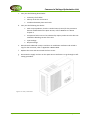
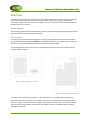
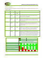
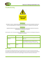
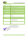
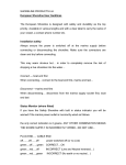
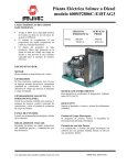
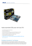
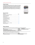
Commercial Voltage Optimisation Unit Table of Contents Introduction ............................................................................................................................................ 3 Purpose ............................................................................................................................................... 5 Important Points ................................................................................................................................. 5 WARNINGS AND CAUTIONS .................................................................................................................... 6 Installation .............................................................................................................................................. 7 Operation .............................................................................................................................................. 12 Under Voltage ................................................................................................................................... 12 Over Current ..................................................................................................................................... 12 Status Indications ............................................................................................................................. 13 Troubleshooting .................................................................................................................................... 14 Warranty ............................................................................................................................................... 14 Technical Specification.......................................................................................................................... 15 Document Revision Revision No. Date Reason for revision 01 08 October 2012 First draft version September 2012 Page 2 of 15 Commercial Voltage Optimisation Unit Introduction This Installation & User Manual covers the installation and use of the Apex Commercial Voltage Optimisation (VO) units. Apex Energy have a range of 3 phase voltage optimisation products ranging from 63A, 100A, 160A and 200A. They have been specifically designed to suit a wide range of applications and can be installed on main incoming supplies or on sub circuits to reduce energy costs on specific loads. The units are self commissioning and are fully automated to ensure optimum savings are achieved as well as ensuring continuity of supply even during bypass operation. The Apex Voltage Optimisation (VO) units are supplied in 2 frame sizes. Each device in the range of Apex Voltage Optimisation (VO) units is supplied complete with a 3 pole mains isolator and LCD display. An optional Moulded Case Circuit Breaker in place of the isolator is available as an extra cost option. Rating Fixing Size 1 63A and 100A Wall Mounted Size 2 160A and 200A Floor Mounted Table 1 All Apex Voltage Optimisation (VO) units feature an LED indicator status to identify the following conditions; “Main On“, “Unit in Save Mode” & “Unit in Bypass Mode“ The LCD display on the front of the unit shows “incoming voltage”, “outgoing voltage” and “current drawn” per phase. The incoming voltage to a site will vary around the country but by law it can be between 216V and 253V (current European Legislation ESQCR 2002). However, sudden voltage surges can damage electronic equipment and cause premature failure due to the stresses a high voltage applies. All electrical equipment is designed to work within a range of 207V and 253V if it complies with European Conformity CE. But, critically, the optimum and most efficient supply voltage for these appliances is 220V. When the supply voltage exceeds 220V wasted power can be generated, as both heat and vibration. This could significantly reduce the life span and efficiency of the equipment. The commercial range of Apex Voltage Optimisation (VO) units feature a “Dual Tap” function. This enables the unit to automatically select the correct tap setting according to the incoming voltage. This offers 2 major benefits. 1) Prevents the site voltage going below the recommended lower voltage. 2) Ensures that even when the incoming voltage drops, the Apex VO unit can automatically adjust to a lower tap setting, ensuring that savings are still being achieved. September 2012 Page 3 of 15 Commercial Voltage Optimisation Unit Electric loads that will deliver energy savings are those that are known as “voltage dependent” loads. Appliances that will benefit from voltage optimisation are typically; Refrigeration loads. Air conditioning without invertors. Electric motors without speed drives. Heating pump motors. Metal Halide / SON Lamps. Incandescent lamps. Compact fluorescent lamps. Fluorescent tubes T8 / T12. Halogen lighting indoor and outdoor. LED lighting. Process loads. * Savings may vary between different manufacturers. In addition to energy saving, the Apex VO unit can also protect your appliances from harmful over voltages and spikes that can significantly reduce the electrical life of sensitive electronic equipment. The Apex VO units have a dedicated electronic control unit (ECU) which intelligently and constantly monitors all the parameters such as incoming voltage, outgoing voltage, load, current, temperature, even its own performance ensuring the unit always delivers the optimum performance to the premises. The Apex VO unit will automatically select the correct level of voltage reduction or even to bypass depending on the algorithm of conditions. Incorporating the latest sine wave sampling (SWS) and active sine wave mapping (ASWM) technology enables the unit to monitor and control three critical performance and safety functions. 1) Low Voltage Threshold (LVT) eliminates the risk of the optimised voltage falling below a minimum target voltage. When it detects the voltage has recovered and stabilised it automatically switches back to 'save' mode. 2) High Current Threshold (HCT) 63A unit and 160A unit only protects against over current. The unit will automatically detect this and remains in a temporary 'bypass' mode until the over current reduces. 3) Optimum Switching Threshold (OST) by constantly mapping the sine wave, the Apex VO unit will only switch at the optimum point, which eliminates any interruption to the supply voltage. It also eliminates spikes and transients. September 2012 Page 4 of 15 Commercial Voltage Optimisation Unit Purpose The purpose of the Apex VO unit is as follows: Reduce energy waste and carbon footprint by reducing the power consumed by appliances. Contribute to Government funded targets on carbon reduction. Generate end user savings, which start immediately after installation. Substantially extend the life of appliances and lighting. Protect sensitive electrical devices from damage. Important Points Familiarise yourself with this manual and the Apex VO unit before installing and / or operating the unit. In particular, ensure that you have read the WARNINGS AND CAUTIONS section. Contact your electrical supplier before breaking any main fuse seals during the installation of this product. Apex Energy recommends, if necessary, that you ask the supplier to install an isolator switch. September 2012 Page 5 of 15 Commercial Voltage Optimisation Unit WARNINGS AND CAUTIONS These warnings and cautions must be observed when installing and/or operating the Commercial Voltage Optimisation Unit. WARNING 1 ELECTRICITY CAN KILL. INSTALLING THIS EQUIPMENT WITHOUT ISOLATING THE SUPPLY IS NOT ONLY DANGEROUS BUT CONTRAVENES THE ELECTRICITY AT WORK REGULATIONS 1989. WARNING 2 MAKE SURE THAT MAXIMUM CONDUCTIVE CABLE SURFACE IS IN CONTACT WITH TERMINALS AND THAT THEY ARE SECURE. LOOSE CONNECTIONS CAN CAUSE ARCING THAT MAY RESULTS IN HEAT DAMAGE TO COMPONENTS AND ULTIMATELY FIRE. WARNING 3 THIS WORK MUST BE CARRIED OUT BY A REGISTERED ELECTRICIAN. CAUTIONS Install the VO unit in free air ventilation Make sure the installation location is clean and dry to prevent any current leakage. The unit must never be covered. September 2012 Page 6 of 15 Commercial Voltage Optimisation Unit Installation The configuration of a typical commercial installation is illustrated in Figure 1. The configuration when integrated with a typical PV installation is illustrated in Figure 2. Figure 1: Typical Commercial Installation Note: Before commencing with the installation: Make sure that you have the correct CSA and length of tails. Add together the total maximum design current of the circuits to be supplied by the Apex VO unit to calculate the conductor size of the cable required; refer to Appendix 6 of the BS7671 On Site Guide; Establish how isolation is to be achieved. If an isolation switch is not installed; check if there is an isolation facility on the meter. As a last resort, remove the supply fuse, this is usually a BS88 or BS371 cartridge type. If seals are fitted, notify the supplier and ask permission before you remove them; Make sure the unit is clean and undamaged prior to installation. September 2012 Page 7 of 15 Commercial Voltage Optimisation Unit Figure 2: Typical installation with PV solar power system September 2012 Page 8 of 15 Commercial Voltage Optimisation Unit 1. The 63A and 100A three phase commercial units can be wall mounted. The 160A and 200A three phase commercial units are recommended for floor mounting only. 2. Cable entries are supplied on either side of the top of the units via the gland plate. 3. Remove the front cover to allow access to the mounting plate fixing and the terminations for the supply and feed cables. a. Secure the base to the wall as follows; 63A and 100A units only b. Choose a location for the base unit of the Apex VO unit, either horizontally or vertically on a solid surface in a convenient position for access and in a well-ventilated and dry location. Ensure the unit has a minimum 100mm clearance all around for ventilation. CAUTION If the unit is to be installed vertically the transformer must be positioned uppermost. c. Measure and mark positions of the six (6) securing screws, according to whether the unit is to be mounted horizontally or vertically. The dimensions of the hole centres are given in Figure 3 d. Drill appropriate size hole for either direct fixing into wood or the correct type of wall plugs for plasterboard, brick etc. e. Use M12 screws with wall plugs if appropriate. Leave the heads of the screws protruding sufficiently to locate in their relative location holes in the base unit. f. Locate the base unit on the M12 screws; if necessary, tighten the screws to prevent any movement of the base unit but do not tighten fully as it should be made possible for the unit to slide in and out of position. Figure 3: Dimensions of mounting hole centres (63A and 100A Wall Mounted Unit Only) 4. Isolate the supply to the premises at the isolation switch, meter, or by removing the supply fuses as applicable. If the supply fuses are removed make sure that the fuse holder is covered with insulation material to prevent any possible contact with live terminals. September 2012 Page 9 of 15 Commercial Voltage Optimisation Unit 5. Remove the tails and connect directly to the Apex VO unit Isolator or Mould Case Circuit Breaker (MCCB) or, if not possible due to inconvenient lengths cut or use new longer tails. If it is necessary to connect longer tails get permission before you remove any seals at the meter. If applicable; connect the tails to the meter; make sure that the connection is in accordance with BS7671 Chapter 13 of the Wiring Regulations 17th Edition i.e: That all the terminal screw is in contact with the conductive part of the cable. There is no excess conductor exposed. 6. Connect the cable tails from the meter to the Apex VO unit and the output cables as follows: a. Connect the cables to the terminals of the triple pole isolator or moulded case circuit breaker at the Apex VO unit. Connect the output cables from the Apex VO unit at the din rail connectors. Refer to Figure 4 for cable installation. Figure 4: Cable installation x 3 for 3 Phase connections b. Connect the correct size earth bonding cable (refer to Chapter 4 of the BS7671 On Site Guide) between the main earth terminal and the chassis of the Apex Voltage Optimisation (VO) unit, using a terminal lug crimped to the earth cable. Note: Leave the main earth conductor (usually 16mm² CSA) connected between the main earth terminal and the distribution board. September 2012 Page 10 of 15 Commercial Voltage Optimisation Unit c. Carry out the following dead checks: Continuity of all cables Polarity of the live and neutral. Insulation between phase and earth. d. Carry out the following live checks: Earth Loop Impedance, check it is within limits (max Zs) for the protective devices installed within the Apex VO unit, refer to BS7671 17th edition chapter 4. Prospective fault current if not obtained by enquiry make sure this does not exceed the breaking current of the unit. Input Voltage Output Voltage. e. Record results obtained in steps c and d on an installation certificate and include a copy for the consumer; refer to Appendix 7 BS7671 OSG. f. Replace the cover and secure with the four screws. g. Re-instate the supply and turn on the Apex VO unit and leave it to go through its selfsetting procedure. Figure 5a: 63A / 100A Unit September 2012 Page 11 of 15 Commercial Voltage Optimisation Unit Operation The Apex VO unit constantly monitors the input supply voltage and current and will automatically control the supply within the parameters of the product. The incoming supply will fluctuate constantly; the Apex VO unit will react as follows;- A “click” noise may be heard from the unit as it changes state, this is normal. Under Voltage The incoming supply will fluctuate constantly; where a risk of under voltage exists the Apex VO unit will automatically revert back to mains voltage. Over Current The Apex VO unit must NOT be subjected to a current on any phase that is above its name plate rating. Suitable thermal protection MUST be installed downstream of the Apex VO unit to protect the unit from irreparable damage that will be caused should this happen. The operating status of the Apex VO unit is indicated by two LED’s in the small circular indicator window. Refer to Figure 7 Figure 7: 63A / 100A Apex VO unit Figure 7b: 160A / 200A Apex VO unit The Apex VO unit will instantly switch to “save“mode when it is powered up and switched on. Should the Apex VO unit detect a low voltage on any one of the three phases it will automatically revert to a bypass condition until the voltage is high enough to allow “save“ mode to be selected. There may be a delay between these states as the Apex VO unit is establishing that the supply voltage has stabilised. September 2012 Page 12 of 15 Commercial Voltage Optimisation Unit Status Indications The status indicated by the LEDs is described in the following table. A graphical representation of this is given in Figure 6. Green LED Red LED Status Description Constant Off “Save” mode The unit is working normally and in “Save” mode. Flashing Single Flashing Internal Testing The unit is conducting internal tests (this will typically occur following a power outage). The unit will revert to “Save” mode once completed. Flashing Single Flashing “Bypass” mode The unit has reverted to “Bypass” mode due to a temporary under voltage. Once the voltage increases to specification levels the unit will automatically revert back to “Save” mode. Flashing Double Flashing “Bypass” mode The unit has reverted to “Bypass” mode due to a temporary over current. Once the current drops the voltage optimisation device will automatically revert back to “Save” mode. Flashing Triple Flashing “Bypass” mode The unit has reverted to “Bypass” mode due to a temporary over temperature. Once the unit temperature drops to specification levels the voltage optimisation device will automatically revert back to “Save” mode. Off Continuous Flashing Unit Shutdown The unit has shutdown either because the incoming voltage has exceeded 290V OR the unit has become too hot OR the unit has exceeded its maximum load. Switching the main Isolator off then on again should reset the unit. Please note that there may need to be a time delay before the unit will reset if it tripped due to over temperature. Table 2 Event Fault Status (RED) indicates a fault condition VO Mode (GREEN) indicates voltage selection mode Number of flashes indicates fault type. Solid for VO Mode. Flashing for Bypass Mode. Power up, Self test Start-up / Bypass mode Normal Voltage Optimizing mode Low input voltage, Bypass mode High Current, Bypass mode Over Temperature, Bypass mode Unit failure Figure 6: Graphical presentation of status indicators September 2012 Page 13 of 15 Commercial Voltage Optimisation Unit Troubleshooting WARNING 4 ELECTRICITY CAN KILL. TROUBLESHOOTING THIS EQUIPMENT WITHOUT ISOLATING THE SUPPLY IS NOT ONLY DANGEROUS BUT CONTRAVENES THE ELECTRICITY AT WORK REGULATIONS 1989. WARNING 5 TROUBLESHOOTING THAT REQUIRES THE REMOVING OF INSULATING COVERS MUST ONLY BE PERFORMED BY A QUALIFIED ELECTRICIAN. CAUTION Removing the cover of the Apex Voltage Optimisation (VO) unit without contacting Apex Energy may invalidate your warranty. LED display Both LEDs not lit on Optimiser Red LED continuously flashing. Status of Unit Action Loss of Power Consult supplier to check if supply power has been cut. Loss of Power Check visually cable from meter to optimiser only qualified electricians should carry out further checks or attempt to reconnect cables. Optimiser Unit Failure Contact your Apex supplier Warranty The Commercial Voltage Optimisation Unit is guaranteed for one year from the date of purchase. The installer will record the serial numbers of the Apex VO unit and the circuit board on the warranty card. This warranty card must be sent to Apex Energy to increase the warranty to three years. September 2012 Page 14 of 15 Commercial Voltage Optimisation Unit Technical Specification Incoming Voltage 232V – 253V Outgoing Voltage 214V – 235V Frequency 50 / 60Hz Voltage Reduction 18v or 9v – Twin Tap automatically selected Humidity 85% Ambient Operating Temperature -20 to +45°C Efficiency >99% Insulation Class BS2757 120 degree maximum IP Rating IP 23 Cooling Case is naturally ventilated Voltage Surge Able to withstand 3.3kv for 60 seconds Breaking Current 10kA Temperature rise @ Full load above ambient 63A = 10 degrees 100A = 10 degrees 160A = 10 degrees 200A = 10 degrees Noise Emissions All units < 5db Operating Current Continuous Maximum current dependant on model, 63A, 100A , 160A, 200A Dimensions 63A - H = 480mm W = 702mm D = 230mm 100A - H = 480mm W = 702mm D = 230mm 160A - H = 600mm W = 700mm D = 300mm 200A - H = 600mm W = 700mm D = 300mm Weight 63A = 42kg 100A = 42kg 160A = 90kg 200A = 90kg INSTALLATION & USER MANUAL COMMERCIAL VOLTAGE OPTIMISATION UNIT Designed, developed and manufactured in the UK by Apex Energy UK St. Johns Road Meadowfield Ind. Est. Durham DH7 8R September 2012 Page 15 of 15