1
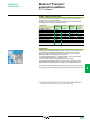
Modicon Premium
automation platform
®
Catalog
2010
™
8001 Knightdale Blvd.
Knightdale, NC 27545
Tel: 919-266-3671
19 Waterman Avenue
Toronto, Ontario M4B 1Y2
Tel: 416-752-8020
http://www.schneider-electric.us/
The information provided in this documentation contains general descriptions and/or technical
characteristics of the performance of the products contained herein. This documentation is not
intended as a substitute for and is not to be used for determining suitability or reliability of these
products for specific user applications. It is the duty of any such user or integrator to perform the
appropriate and complete risk analysis, evaluation and testing of the products with respect to the
relevant specific application or use thereof. Neither Schneider Electric nor any of its affiliates or
subsidiaries shall be responsible or liable for misuse of the information contained herein.
Please note: not all parts listed in this catalog are available in all countries.
Design: Schneider Electric
Photos: Schneider Electric
ART. 960268
02/2010
MKTED208054EN-US
Schneider Electric - North American Operating Division
2010
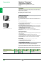
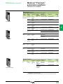
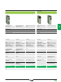
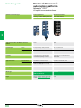
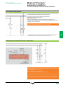
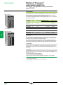
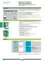
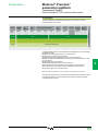
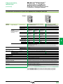
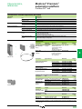
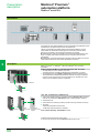
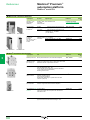
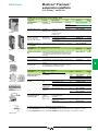
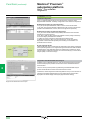
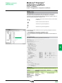
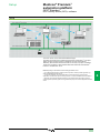
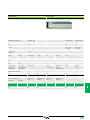
Modicon® Premium™ automation platform
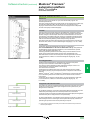
A full range of catalogs for . . . . .
Modicon® Premium™
automation platform
Catalog
2010
Detection
Automation
Automation
Operator dialog
Motion and Drives
&
&
&
&
&
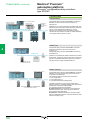
Global Detection
Electronic and
electromechanical sensors
Modicon® Momentum™
distributed I/O and control
Twido® programmable
controller and Twido Suite™
software
Control and signalling
components
Lexium® 32 Servo Drives
motion control
Catalog 2009/2010
MKTED208052EN
Photo-electric sensors
Proximity sensors
Capacitive proximity sensors
Ultrasonic sensors
Limit switches
Pressure switches
Rotary encoders
Radio frequency identification
Machine cabling accessories
MKTED205061EN
&
Modicon® Quantum™
automation platform
Catalog 2009
MKTED208011EN-US
&
Modicon® Premium™
automation platform
Catalog 2010
MKTED208054EN-US
&
Modicon M340 and
Unity software
®
™
DIA6ED2081007EN
PLCs
Discrete, analog I/O and
application-specific solutions
Communication
DIA3ED2090202EN
Controller base
Discrete, analog I/O
Communication
&
Automation functions,
relays, interfaces and
power supplies
MKTED208031EN
Control and signalling units
Control stations & enclosures
Cam switches
Beacons and indicator banks
Pendant control stations
Controllers
Emergency stops
Foot switches
&
DIA7ED2090405EN-US
Motion controllers
Servo drives and Servo motors
Stepper motors and drives
Integrated drives
Modicon Premium
motion control modules
&
MKTED207031EN
Human-Machine interfaces
Soft starters and variable
speed drives
Smart relays
Timing relays
Measurement & control relays
Analog interfaces
Counters
Plug-in relays
Interfaces for discrete signals
Power supplies & transformers
MKTED206071EN
MKTED206111EN
Operator interface terminals
Industrial PCs
HMI and SCADA PC-based
software
Soft starters and variable speed
drives
Software
PLCs and safety controllers
programming software
Software
Vijeo Designer
Operator terminal software
Not all products shown in this catalog are available in every country. Check individual country’s web site or Sales Office for product availability.
See on: www.schneider-electric.com
Software
Software for drives
Motor control programming
software
. . . . Automation & Control functions
Motor control
&
Motor starter solutions
Control and protection
components
MKTED205103EN
Contactors
Circuit-breakers, fuse carriers
Thermal relays
Combinations, motor controllers
Mounting solutions
Motor starter mounting kits
Machine safety
This catalog contains
Automation and Control function
products relating to machines
Safety
&
Preventa™
Machine Safety Products
Catalog 2009
MKTED208051EN-US
Safety PLCs
Safety controllers
Safety monitors
Safety solutions on AS-Interface
cabling system
Safety switches
Safety light curtains
Safety mats
Emergency stops
Control stations
Enabling switches
Foot switches
Beacons & indicator banks
Switch disconnectors
Thermal-magnetic motor circuit
breakers
Enclosed D.O.L. starters
Software
XPSMFWIN configuration
software
XPSMCWIN configuration
software
Interfaces and I/O
Power supplies
&
&
Terminal blocks
Phaseo® power supplies
and transformers
MKTED207011EN
Terminal blocks
Cable ends
&
Advantys™ STB
IP 20 distributed
inputs/outputs
MKTED208053EN
Modules for automation island
Network interfaces
Power distribution
Digital I/O, analogs and
application-specific
Software
STB configuration software
DIA3ED2061209EN
Switch mode power supplies
Filtered rectified power supplies
Transformers
Systems & architectures
This catalog contains
Automation and Control function
products relating to
Communication
&
Machine & Installations with
industrial communication
MKTED207012EN
Preferred implementations
Ethernet TCP/IP, the universal
communication standard
CANopen for machines and
installations
AS-interface, simple and safe
Products
Human-Machine interface
Controllers and PLCs
Field devices
Infrastructure and wiring
Gateways
Software and tools
Collaborative Automation
Partner Program & Partners
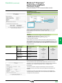
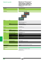
General contents
Modicon® Premium™
automation platform
1 – Premium™ processors
Unity™ selection guide . . . . . . . . . . . . . . . . . . . . . . . . . . . . . . . . . . . . . . . . . . . . 1/2
Unity processors . . . . . . . . . . . . . . . . . . . . . . . . . . . . . . . . . . . . . . . . . . . . . . . . 1/4
PL7™ selection guide . . . . . . . . . . . . . . . . . . . . . . . . . . . . . . . . . . . . . . . . . . . . 1/16
PL7 processors . . . . . . . . . . . . . . . . . . . . . . . . . . . . . . . . . . . . . . . . . . . . . . . . 1/18
2 – Racks, I/O architectures and power supplies
Power supply and fan modules. . . . . . . . . . . . . . . . . . . . . . . . . . . . . . . . . . . . . 2/2
Single rack configuration . . . . . . . . . . . . . . . . . . . . . . . . . . . . . . . . . . . . . . . . . 2/6
Multi-racks configuration without remote module . . . . . . . . . . . . . . . . . . . . . 2/8
Multi-racks configuration with remote module . . . . . . . . . . . . . . . . . . . . . . . 2/12
3 – Discrete and analog I/O
Discrete I/O modules . . . . . . . . . . . . . . . . . . . . . . . . . . . . . . . . . . . . . . . . . . . . . 3/2
Analog I/O modules . . . . . . . . . . . . . . . . . . . . . . . . . . . . . . . . . . . . . . . . . . . . . 3/20
Distributed I/O modules. . . . . . . . . . . . . . . . . . . . . . . . . . . . . . . . . . . . . . . . . . 3/28
TeSys® Quickfit for motor starter components . . . . . . . . . . . . . . . . . . . . . . . 3/42
4 – Application-specific modules and solutions
Preventa™ machine safety modules . . . . . . . . . . . . . . . . . . . . . . . . . . . . . . . . . 4/2
Counter and electronic cam modules . . . . . . . . . . . . . . . . . . . . . . . . . . . . . . . 4/18
Motion control modules . . . . . . . . . . . . . . . . . . . . . . . . . . . . . . . . . . . . . . . . . . 4/32
Integrated weighing system . . . . . . . . . . . . . . . . . . . . . . . . . . . . . . . . . . . . . . 4/54
Hot Standby redundancy (Unity) . . . . . . . . . . . . . . . . . . . . . . . . . . . . . . . . . . 4/60
Warm Standby redundancy (PL7) . . . . . . . . . . . . . . . . . . . . . . . . . . . . . . . . . . 4/70
5 – Communication
Selection guides . . . . . . . . . . . . . . . . . . . . . . . . . . . . . . . . . . . . . . . . . . . . . . . . . 5/2
Ethernet network - Transparent Ready® . . . . . . . . . . . . . . . . . . . . . . . . . . . . . 5/12
CANopen machine bus . . . . . . . . . . . . . . . . . . . . . . . . . . . . . . . . . . . . . . . . . . 5/62
AS-Interface® sensor/actuators bus . . . . . . . . . . . . . . . . . . . . . . . . . . . . . . . . 5/68
X-Way™ bus and network . . . . . . . . . . . . . . . . . . . . . . . . . . . . . . . . . . . . . . . . . 5/74
Modbus Plus™ network and Profibus DP/InterBus® buses. . . . . . . . . . . . . . . 5/90
Modbus®, Uni-Telway™ and asynchronous serial links . . . . . . . . . . . . . . . . 5/100
3
0
6 – Software
Unity™ software . . . . . . . . . . . . . . . . . . . . . . . . . . . . . . . . . . . . . . . . . . . . . . . . . 6/2
PL7™ software . . . . . . . . . . . . . . . . . . . . . . . . . . . . . . . . . . . . . . . . . . . . . . . . . . 6/60
Vijeo® Citect® supervisory software . . . . . . . . . . . . . . . . . . . . . . . . . . . . . . . . 6/90
OPC Factory Server (OFS)™ software . . . . . . . . . . . . . . . . . . . . . . . . . . . . . . 6/100
7 – Human/Machine Interfaces
Magelis® Small Panel units and terminals. . . . . . . . . . . . . . . . . . . . . . . . . . . . . 7/2
Magelis Advanced Panel . . . . . . . . . . . . . . . . . . . . . . . . . . . . . . . . . . . . . . . . . . 7/4
HMI software . . . . . . . . . . . . . . . . . . . . . . . . . . . . . . . . . . . . . . . . . . . . . . . . . . . . 7/6
8 – Connection interfaces and power supplies
Advantys™ Telefast® ABE 7 pre-wired system . . . . . . . . . . . . . . . . . . . . . . . . . 8/2
Phaseo® Universal range power supplies . . . . . . . . . . . . . . . . . . . . . . . . . . . 8/20
Phaseo AS-Interface® range switch mode power supplies. . . . . . . . . . . . . . . 8/34
9 – Services
Treatement for severe environments
Conformal Coating Premium modules . . . . . . . . . . . . . . . . . . . . . . . . . . . . . . 9/2
TSX™ PSY power supply module selection document . . . . . . . . . . . . . . . . . . 9/6
Technical information
Standards, certifications and environment conditions . . . . . . . . . . . . . . . . . . 9/8
Ethernet network, infrastructure . . . . . . . . . . . . . . . . . . . . . . . . . . . . . . . . . . 9/12
Automation product certifications . . . . . . . . . . . . . . . . . . . . . . . . . . . . . . . . . 9/18
MFB (Motion Function Blocks) Library
Motion Control . . . . . . . . . . . . . . . . . . . . . . . . . . . . . . . . . . . . . . . . . . . . . . . 9/20
Index
Product reference index . . . . . . . . . . . . . . . . . . . . . . . . . . . . . . . . . . . . . . . . 9/22
1
1
2
3
4
5
6
7
8
9
10
1/0
2
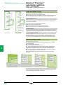
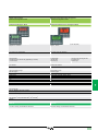
Contents chapter 1
Modicon® Premium™ processors 1
1.1 - Premium processors - Unity™
Processors and slot-PLCs Selection guide ���������������������������������������������������� 1/2
b Premium processors
v
v
v
v
v
Presentation�������������������������������������������������������������������������������������������������� 1/4
Description���������������������������������������������������������������������������������������������������� 1/5
Memory structure������������������������������������������������������������������������������������������ 1/8
Characteristics�������������������������������������������������������������������������������������������� 1/10
References ������������������������������������������������������������������������������������������������ 1/12
1
2
b PCMCIA memory extension cards������������������������������������������������������������������ 1/14
1.2 - Premium processors - PL7™
Processors Selection guide���������������������������������������������������������������������������� 1/16
b Premium processors
v
v
v
v
v
Presentation������������������������������������������������������������������������������������������������
Description��������������������������������������������������������������������������������������������������
Characteristics��������������������������������������������������������������������������������������������
Memory structure����������������������������������������������������������������������������������������
References . . . . . . . . . . . . . . . . . . . . . . . . . . . . . . . . . . . . . . . . . . . . . . . . .
1/18
1/19
1/20
1/22
1/23
3
4
b PCMCIA memory extension cards������������������������������������������������������������������ 1/24
5
6
7
8
9
10
1/1
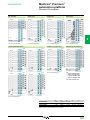
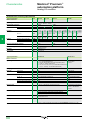
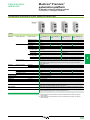
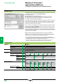
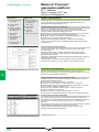
Selection guide
Modicon® Premium™
automation platform
0
Premium processors
Unity™ Pro software
Premium™ platform for Unity™ Pro software offer
TSX™ 57 0p processor
TSX 57 1p processors
1
2
3
g
Number of racks (according to rack type)
1 with 4, 6, 8 or 12 slots
4 with 4, 6, or 8 slots or 2 with 12 slots
In-rack I/O (1)
Analog I/O
256 channels (8-, 16-, 32- or 64-channel
module)
12 channels (4-, 8- or 16-channel module)
512 channels (8-, 16-, 32- or 64-channel
module)
24 channels (4-, 8- or 16-channel module)
Max. no. of channels
Integrated counter (max. 40 kHz)
Counter
4
8
–
Modules with 2/4 counter channels 1 MHz max., single-channel electronic cam module
Motion (2)
Modules with 1/2 axes for stepper motors, 2/3/4 axes for analog control servo motors, 8/16 axes
with SERCOS™ digital link
Module for 8 load cells (2 application-specific channels)
TSX SCY in-rack communication modules (1 application-specific channel)
RS 232, RS 485 or current loop (3) (4) master/slave PCMCIA modules and RS 485 master/
slave in-rack communication modules
1 integrated RS 485 master/slave channel, RS 232, RS 485 or current loop (3) (4) master/slave
PCMCIA modules and RS 485 master/slave in-rack communication modules
1 integrated RS 485 channel, RS 232, RS 485 or current loop PCMCIA modules (3) (4)
and RS 485 in-rack communication modules
1 in-rack module
2 in-rack modules
In-rack applicationspecific channels
4
Serial link
connections
Character mode
Bus connections
7
Weighing
Serial links
Modbus®
Uni-Telway™
5
6
Discrete I/O
Network connections
AS-Interface® actuator/sensor
bus master V2
CANopen machine bus
master V4.02
InterBus® fieldbus master V2 (5)
or Profibus DP™ fieldbus master V0
Class 1 and 2 (5)
8
Ethernet
Multiprotocol in-rack modules (Modbus /TCP, Uni-TE™, Global Data, I/O Scanning, TCP Open),
Web server, FactoryCast™ server or FactoryCast HMI server
Fipway module (4), Ethway in-rack modules
Modbus Plus (3), Fipway (3)(4) modules,
Ethway in‑rack modules
Configurable loops
Programmable loops
–
Process control EFB library
–
Without PCMCIA extension
96 Kb program and data
With PCMCIA extension
128 Kb program
224 Kb program
96 Kb data
96 Kb data
256 Kb (PCMCIA extension in upper slot (0) on processor)
–
100…240 V a, 24 c non-isolated and 24…48 V c isolated power supply. A power supply is
required for each rack.
Data storage
USB programming port
Power supply
9
Premium processor
Integrated Ethernet
(9)
Integrated CANopen
96 Kb program and data
TSX P57 104M
TSX P57 1634M
Standard
TSX P57 0244M
g
TSX P57 154M (11)
Pages
1/12
(1) The maximum values for the numbers of discrete and analog I/O are cumulative (with the exception of TSX H57 24M/44M Hot Standby processors).
(2) 1 axis = 1 application-specific channel, except for SERCOS modules where, depending on the configuration, the module = 2…32 channels.
(3) Module to be inserted into the lower PCMCIA slot (no. 1).
(4) Module to be inserted into the TSX SCY 21 601 in-rack communication module slot.
(5) The InterBus and Profibus DP limits are not cumulative.
(11) The TSX P57 154M processor does not support the CANopen bus PCMCIA module.
Integrated Fipio®
10
–
1
Hot Standby availability
Memory capacity
1 PCMCIA module (3)
Max. no. of networks
Fipway®/Ethway™/Modbus Plus™
modules
Integrated process
control
1 integrated PCMCIA module
1/2
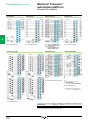
TSX 57 2p processors and slot PLCs TSX 57 3p processors and slot
PLCs
0
TSX 57 4p processors
n
TSX 57 5p
processors
TSX 57 6p
processors
1
n
n
1 with 6, 8 or 12
slots
16 with 4, 6, or 8 slots or 8 with 12 slots
1 with 6, 8 or 12
slots
16 with 4, 6, or 8 slots or 8 with 12 slots
512 channels (64channel modules)
80 channels (16channel modules)
18
–
–
1024 channels (8-, 16-, 32- or 64-channel modules)
512 channels (64channel modules)
128 channels (16channel modules)
18
2048 channels (8-, 16-, 32- or 64-channel modules)
80 channels (4-, 8- or 128 channels (4-, 8- or 16-channel
16-channel modules) modules)
24
32
3
256 channels (4-, 8- or 512 channels (4-, 8- or 16-channel
16-channel modules) modules)
64
Modules with 2/4 counter channels, single-channel
–
Modules with 2/4 counter channels, single-channel electronic
electronic cam
cam
–
Modules with 1/2 axes for stepper motors, 2/3/4 axes for
–
Modules with 1/2 axes for stepper motors, 2/3/4 axes for
servo motors, 8/16 axes with SERCOS digital link
servo motors, 8/16 axes with SERCOS digital link
–
Module for 8 load cells (2 application-specific channels)
–
Module for 8 load cells (2 application-specific channels)
TSX SCY in-rack communication modules (1 application-specific channel)
RS 232, RS 485 or current loop (3) (4) master/slave PCMCIA modules and RS 485 master/slave in-rack communication modules
1 integrated RS 485 master/slave channel, RS 232, RS 485 or current loop (3) (4) master/slave PCMCIA modules and RS 485 master/slave in-rack communication
modules
1 integrated RS 485 channel, RS 232, RS 485 or current loop PCMCIA modules (3) (4) and RS 485 in-rack communication modules
–
4 in-rack modules
–
–
8 in-rack modules
–
8 in-rack modules
1 PCMCIA module (3)
–
1 PCMCIA module (3)
1 in-rack module
–
4 in-rack modules
3 in-rack modules
5 in-rack modules
2
2 + 1 software
3
3 + 1 software
4
gateway
gateway
®
™
Multiprotocol in-rack modules (Modbus /TCP, Uni-TE , Global Data, I/O Scanning (6), TCP Open), Web server, FactoryCast server or FactoryCast HMI server
–
Modbus Plus™ (3), Fipway (3)(4) module,
Ethway in-rack modules
10 channels with 3 loops max.
Process control EFB library
Yes
–
15 channels with 3 loops max.
160/192 Kb program and data (8)
192/208 Kb program and data (8)
–
Modbus Plus (3), Fipway (3) (4) (7) module,
Ethway in-rack modules
20 channels with 3 loops max.
Yes
(10)
TSX P57 204M
TSX P57 2634M
TSX P57 304M
TSX P57 3634M
440 Kb program and data
TSX P57 254M
TSX P57 354M
TSX H57 44M
(10)
4
5
6
7
30 channels with 3 loops max.
–
768 Kb program
1.75 Mb program
2 Mb program
160/192 Kb data (8)
192/208 Kb data (8)
440 Kb data
8 Mb (PCMCIA extension in upper or lower slot (0 or 1) on processor)
–
1
100…240 V a, 24 V c non-isolated and 24…48 V c isolated power supply. A power supply is required for each rack.
TSX H57 24M
2
1 Mb program and
data
7 Mb program
1 Mb data
2 Mb program and
data
7 Mb program
2 Mb data
TSX P57 4634M
TSX P57 5634M TSX P57 6634M
TSX P57 454M
TSX P57 554M
4/69
1/12
1/12
1/21
1/13
4/69
1/13
(6) TSX H57 24M/44M Hot Standby processors do not support the Ethernet I/O Scanning service.
(7) TSX P57 4634M/5634M/6634M processors with integrated Ethernet port do not support the PCMCIA Fipway card.
(8) The second value applies to TSX P57 254M/354M processors with integrated Fipio link and to the TSX H57 24M Hot Standby processor.
(9) The integrated Ethernet port requires one of the available network connections.
(10) The integrated Ethernet port is dedicated to Hot Standby communication (CPU Sync link between “Primary” and “Redundant” processors).
8
9
10
n New feature
1/3
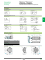
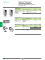
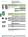
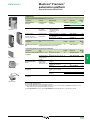
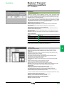
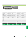
Presentation
Modicon® Premium™
automation platform
0
Unity™ processors
Presentation
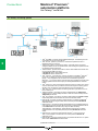
Modicon® Premium™ TSX™ P57 pp4M, TSX P57 pp34M and TSX Hp4M automation
platform processors manage the entire PLC station comprising:
b Discrete I/O modules
b Preventa™ safety modules
b Analog I/O modules
b Application-specific modules (counter, motion, weighing, communication)
1
n The Premium processor offer has seen the addition of three new references:
2
b TSX P57 6634M, high-end processor with 1 integrated Ethernet Modbus®/TCP
port and an internal 2 Mb RAM
b TSX H57 24M/44M, that supports the Hot Standby system (with "Primary" and
"Secondary" PLCs), see pages 4/60 to 4/69
The processors differ in terms of their memory capacities, processing speeds, the
number of I/O and the number of communication ports.
Depending on the model, they include:
b 1 to 16 racks interconnected by means of Bus X (max. distance: 700 m)
b 192 to 2040 discrete I/O
b 12 to 512 analog I/O
b 4 to 64 application-specific channels. Each application-specific module (counter
motion control, communication or weighing) accounts for one or more applicationspecific channels.
b 1 to 4 networks (Ethernet Modbus/TCP, Fipway®, Modbus Plus™, Ethway), 1 to 8
AS‑Interface buses
b 0 or 1 Fipio® bus, 0 or 1 CANopen or Modbus Plus bus and 0 to 5 InterBus® or
Profibus DP™ (1) fieldbuses
b 0 to 30 process control channels, with each channel capable of supporting up to
3 loops
3
4
5
Depending on the model, Premium™ processors also feature:
b A 10BASE-T/100BASE-TX Ethernet Modbus/TCP port (RJ45 connector)
b A 1 Mbit/s Fipio bus link (bus manager)
b Communication via 2 terminal ports (TER and AUX) using Uni-Telway or character
mode protocol (typically a 19 or 115 Kbit/s programming terminal and an operator
dialog terminal)
b A USB type TER port (for connecting a programming terminal)
6
Each processor has two slots for a PCMCIA card:
b An upper slot (no. 0) for battery-backed memory extension cards (program,
symbols, constants and/or data files)
b A lower slot (no. 1) for (1) a network card (Fipway, Modbus Plus) or bus
(CANopen, Fipio Agent, Modbus, Uni-Telway and serial links). Memory extension
cards intended specifically for storing data can also be inserted into this slot.
7
Treatment for harsh environments
n If the Modicon Premium automation platform is destined for use in extremely
harsh environments, the "conformal coating" offer is available. This involves applying
a coat of "humiseal 1A33" varnish to the electronic cards of the processor and power
supply modules, I/O modules on Bus X and the racks. See page 9/2.
8
Premium application design and installation
The installation of these Premium processors requires:
b Unity™ Pro Medium, Large or Extra Large programming software. This is the same
as the software for installing the Modicon M340 and Modicon Quantum platforms.
b Optionally, depending on requirements:
v The Unity Application Generator (UAG) specialist software for modelling and
generating process applications
v Unity EFB toolkit software for developing EF and EFB libraries in C language
v Unity SFC View software for visualizing and diagnosing applications written in
Sequential Function Chart (SFC) or Grafcet language
9
___________________________________________________________________________
(1) TSX H57 24M/44M Hot Standby processors do not support the following buses or networks:
Fipio, CANopen, Modbus Plus, InterBus and Profibus DP.
10
n New feature
1/4
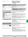
Modicon® Premium™
automation platform
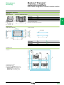
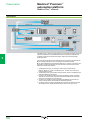
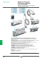
Description
0
Unity™ processors
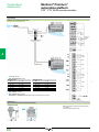
TSX™ P57pp4M processors without integrated Ethernet port
8
1
2
3
4
5
6
7
TSX P57 154M
TSX P57 104M
1
2
3
4
5
6
7
TSX P57 204M/304M
TSX P57 1p4M single-format processors and TSX P57 2p4/3p4M double-format
processors feature the following on the front panel:
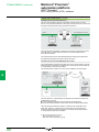
1 A display block with 5 LEDs:
v RUN LED (green): Processor in operation (program running)
v ERR LED (red): Controller detected fault on the processor or its on-board devices
(PCMCIA memory card and PCMCIA communication card)
v I/O LED (red): Controller detected fault occurring on another station module or
configuration fault
v TER LED (yellow): Activity on TER or AUX terminal port
v FIP LED (red): Activity on integrated Fipio® bus (depending on model)
2 RESET button causing a cold restart of the PLC when it is activated
3 An 8-way female mini-DIN connector marked TER for connecting a programming
or adjustment terminal (RS 485)
4 An 8-way female mini-DIN connector marked AUX for connecting a programming,
adjustment or operator dialog terminal (RS 485)
5 A PCMCIA slot (no. 0) for a memory card
6 A PCMCIA slot (no. 1) for a communication card or memory extension card for
storing additional data
7 A 9-way SUB-D connector (on TSX P57 154/254/354M models) for Fipio bus
communication (Fipio manager port)
8 An air recirculating heatsink (on TSX P57 0244/1p4M models)
1
2
3
4
TSX P57 254M/354M/454M
Processor with integrated CANopen port
7
1
2
3
4
5
6
TSX P57 0244M
The TSX P57 0244M processor features:
1 A display block with 4 LEDs:
v RUN LED (green): Processor in operation (program running)
v ERR LED (red): Controller detected fault on the processor or its on-board devices
(PCMCIA memory card and PCMCIA communication card)
v I/O LED (red): Controller detected fault occurring on another station module or
configuration fault
v TER LED (yellow): Activity on TER or AUX terminal port
2 RESET button causing a cold restart of the PLC when it is activated
3 An 8-way female mini-DIN connector marked TER for connecting a programming
or adjustment terminal (RS 485)
4 An 8-way female mini-DIN connector marked AUX for connecting a programming,
adjustment or operator dialog terminal (RS 485)
5 A PCMCIA slot (no. 0) for a memory card
6 A PCMCIA slot (no. 1) equipped with PCMCIA CANopen master V4.02 card,
complete with cordset and tap junction (see page 5/65)
7 An air recirculating heatsink.
5
6
7
8
9
10
1/5
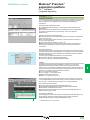
Description (continued)
Modicon® Premium™
automation platform
0
Unity™ processors
1 3
2
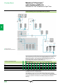
TSX™ P57 pp34M processors with integrated Ethernet port
1
4
5
6
7
2
8
TSX P57 1634M/2634M/3634M
3
4
5
6
7
8
9
10
1/6
TSX P57 1634M/2634M/2834M double-format processors with integrated
Ethernet Modbus®/TCP port feature, on the front panel:
1 A display block with 5 LEDs:
v RUN LED (green): Processor in operation (program running)
v ERR LED (red): Controller detected fault on the processor or its on-board devices
(PCMCIA memory card and PCMCIA communication card)
v I/O LED (red): Controller detected fault occurring on another station module or
configuration fault
v TER LED (yellow): Activity on TER or AUX terminal port
2 A display block relating to the integrated Ethernet port featuring 5 LEDs:
v RUN LED (green): Ethernet port ready
v ERR LED (red): Ethernet port operative
v COL LED (red): Collision detection
v STS LED (yellow): Ethernet link diagnostics
v Two TX and RX LEDs (yellow): Transmission/reception activity
3 RESET button causing a cold restart of the PLC when it is activated
4 An 8-way female mini-DIN connector marked TER for connecting a programming
or adjustment terminal (RS 485)
5 An 8-way female mini-DIN connector marked AUX for connecting a programming,
adjustment or operator dialog terminal (RS 485)
6 An RJ45 connector for connection to the
Ethernet Modbus/TCP 10BASE-T/100BASE‑TX network
7 A PCMCIA slot (no. 0) for a memory card
8 A PCMCIA slot (no. 1) for a communication card or memory extension card for
storing additional data
Description (continued)
Modicon® Premium™
automation platform
0
Unity™ processors
1 2
1 2
3
4
5
6
7
8
TSX P57 454M/554M
9
TSX P57 4634M/5634M
TSX P57 6634M
TSX™ P57 4p4/5p4/6634M and TSX H57 p4M
high‑performance processors (1)
Modicon® Premium™ double-format high-performance processors
TSX P57 454/554M/4634M/5634M/6634M and TSX H57 24M/44M (1) feature the
following on the front panel:
1 A display block with 5 LEDs:
v RUN LED (green): Processor in operation (program running)
v ERR LED (red): Controller detected fault on the processor or its on-board devices
(PCMCIA memory card and PCMCIA communication card)
v I/O LED (red): Controller detected fault occurring on another station module or
configuration fault
v TER LED (yellow): Activity on the AUX terminal port
v FIP LED (red): Activity on integrated Fipio bus (TSX P57 454/554M model)
In the case of models with an integrated Ethernet port
(TSX P57 4634M/5634M/6634M), this display block features 6 additional LEDs:
v RUN LED (green): Ethernet port ready
v ERR LED (red): Ethernet port inoperative
v COL LED (red): Collision detection
v STS LED (yellow): Ethernet link diagnostics
Two TX and RX LEDs (yellow): Transmission/reception activity
2 A "Memory extract" button for extracting the PCMCIA memory extension card.
The associated "Memory extract ready" LED indicates that this card can be
extracted safely.
3 RESET button causing a cold restart of the PLC when it is activated
4 An 8-way female mini-DIN connector marked AUX for connecting a programming,
adjustment or operator dialog terminal
5 A USB type connector marked TER for connecting a programming terminal
(requires the PC-compatible 3 m connection cable, reference UNY XCA USB 033,
to be ordered separately)
6 A PCMCIA slot (no. 0) for a memory extension card
7 A PCMCIA slot (no. 1) for a communication card or memory extension card for
storing additional data
8 A 9-way SUB-D connector (on TSX P57 454M/554M models) for Fipio bus
communication (Fipio manager port)
9 An RJ45 connector (on TSX P57 4634M/5634M/6634M models) for connection to
the Ethernet Modbus/TCP 10BASE-T/100BASE-TX network
1
2
3
4
5
6
USB port
The USB port 5 boasts a faster useful data rate (12 Mbit/s) than the Uni-Telway
terminal port available on Premium processors. The USB port is compatible with
Unity Pro programming software and the OPC Factory Server (OFS).
TSX P57 4p4M/5p4M/6634M processors can be connected to a USB bus
comprising several peripheral devices. However:
b Only one processor must be connected to the USB bus
b No device on the USB bus (modem, printer) can be controlled by the PLC.
7
8
__________________________________________________________________
(1) TSX H57 24M/44M Hot Standby processor, see description on page 4/61.
9
10
1/7
Memory structure
Modicon® Premium™
automation platform
0
Unity™ processors
Memory structure
1
Processor without PCMCIA memory card
2
Internal RAM
96 to 2048 Kb
Located data
Global and DFB
unlocated data
Program, symbols and area
for online program
modification
Constants
3
Processor with PCMCIA memory card in slot no. 0
4
Internal RAM
96 to 2048 Ko
Located data
DFB unlocated data
128 to 7168 Ko
Program and symbols
PCMCIA card
(slot no. 0)
Constants
Additional data storage
6
2 Area in internal RAM or PCMCIA memory card for the program and symbols. If
this area happens to be inside the internal RAM, it also contains the area for
modifying the program in online mode (1).
This area contains the program's executable binary code and IEC source code.
The user selects the type of information to be stored in the PLC memory.
4 Area for storing additional data (slot no. 0 or no. 1), e.g. for production data and
manufacturing recipes
Memory organization
The memory will be organized in one of two ways, depending on whether the
Premium processor is fitted with 0, 1 or 2 memory extension cards:
b Application in internal RAM: In this case, the application is completely loaded into
the processor's internal battery-backed RAM (2), the capacity depends on the
processor model (96 Kb to 2 Mb).
b Application in PCMCIA card: In this case, the internal RAM is reserved for the
application data. The PCMCIA memory card (slot no. 1) contains the program space
(program, symbols and constants areas) (128 Kb to 2 Mb). Certain types of PCMCIA
memory card also host the data storage area (max. 6976 Kb).
Symbols areas
Processor with data storage type memory card in slot no. 0
Internal RAM
96 to 2048 Kb
Located data
7
1 The application data that is in the internal RAM, is divided into two possible types:
v Located data, corresponding to data defined by an address (e.g. %MW237), that
can have a symbol linked to it (e.g. Counter_rejects).
v Unlocated data, corresponding to data defined only by a symbol. This type of
addressing eliminates the problems of memory mapping management, because
addresses are assigned automatically. It also facilitates data structuring.
v DFB unlocated data, corresponding to DFB user function block data. The size of
this area is determined by the physical size of the available internal RAM. The
available RAM depends on the processor model, see pages 1/12 and 1/13.
3 Constants area in the internal RAM or the PCMCIA memory card (slot no. 0)
Global unlocated data
DFB unlocated data
5
The application memory is divided into memory areas, that are physically distributed
across the internal RAM and 0, 1 or 2 PCMCIA memory extension cards:
Having the symbols area in the same place as the program area is optional.
However, if the application symbols database is available on the PLC, it means that,
when an empty programming terminal is connected to the PLC, the elements
needed to debug or upgrade this PLC can be transferred to the terminal.
Unlocated data
Program, symbols and area
for online program
modification
8
PCMCIA data
storage card
(slot no. 0)
9
10
1/8
4096 or 8192 Ko
Constants
Additional data storage
__________________________________________________________________
(1) If a PCMCIA card has been inserted, it is the memory on this memory card that will be used
for the purpose of modifying the program in online mode (outside areas 2, 3 and 4 opposite).
(2) The internal RAM is backed up by an optional battery (with a service life of 3 years). The
battery is located in the power supply module (see page 2/4).
Memory structure (continued)
Modicon® Premium™
automation platform
0
Unity™ processors
Internal RAM
96 to 2048 Ko
Processor with mixed type memory card in slot no. 0 and data
storage type memory card in slot no. 1 (1)
Located data
Global and DFB unlocated
data
PCMCIA card
(slot no. 0)
128 to 7168 Ko
Program and
symbols
Constants
PCMCIA data
storage card
(slot no. 1)
4096 or 8192 Ko
Additional data
storage (zone A)
Additional data
storage (zone B)
Memory structure (continued)
Extension of the data storage area
Memory cards reserved for data storage (4096 or 8192 Kb) are used to:
b Access the data storage area in cases where the application is fully loaded into the
internal RAM. In this case, the data storage memory card is inserted into PCMCIA
slot no. 0.
b Free up memory to serve as additional program space when the application is on
the PCMCIA card (slot no. 0). In this case, the data storage memory card is inserted
into PCMCIA slot no. 1 (although the memory card in slot no. 0 can still be used for
some of the data).
2
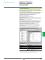
Unity™ Pro programming software helps the application designer to manage the
structure and organize how the memory space on the Premium PLC is occupied.
Protecting the application
Regardless of the PLC memory structure (whether the application is located in the
internal RAM or on the PCMCIA card), it is possible to prevent the application from
being accessed (for the purpose of reading or modifying the program) by only
loading the executable code into the PLC.
A memory protection bit, set in configuration mode, is also available to prevent any
program modification (via the programming terminal or downloads).
Program modification in online mode
(1) TSX P57 20 processors and higher
1
This function is different from previous versions of Modicon® Premium™ PLCs (with
PL7 software) in that it now allows program code and data from different parts of the
application to be added or modified in a single modification session (thus making
modification unified and consistent with regard to the controlled process).
This increased flexibility comes at a cost in terms of the amount of program memory
required. In order for the program to be modified in online mode, the amount of
program memory space available must be at least equal to the combined size of the
sections of the Unity Pro program affected by the single modification session
concerned.
Depending on circumstances:
b In the case of a processor with a memory extension card, there will be sufficient
memory left on the card for online modification, provided that the recommendations
on page 1/22 are observed.
b In the case of a processor without a memory extension card, if the user wants to
be able to make modifications in online mode, he or she must select a processor on
the basis of the following:
v The anticipated size of the application
v The number and size of the program sections to be modified in online mode
3
4
5
6
7
Note: A memory extension card based exclusively on Flash EPROM technology (without
additional SRAM) is clearly incapable of supporting online program modifications.
8
9
10
1/9
Modicon® Premium™
automation platform
Characteristics
Unity™ processors
1
2
Modicon® Premium™ PLCs have been developed to comply with major national and international standards on electronic industrial automation
equipment. See pages 9/8 to 9/19 "Standards, certification and environmental conditions".
Characteristics and performance
Types of processor
Maximum
configuration
4/6/8 slots
12 slots
Max. no. of slots for modules
Functions
Max. no in-rack Discrete I/O
(3)
Analog I/O
Process control
channels
TSX P57
0244M
1
1
12
No. of racks
Integrated
connections
Max. no. of
connections
4
5
Memories
Execution time Without
for one
PCMCIA card
instruction
8
9
10
Tasks
With PCMCIA
card
No. of
Kinstructions
executed
every ms
TSX P57
204M
16
8
128
TSX P57
2634M (1)
TSX P57
254M
Counter, axis control, weighing and serial links (Modbus®, Uni-Telway™ and asynchronous)
Serial link
Network (Ethernet,
Fipway®, Ethway,
Modbus Plus™)
–
1
(63 agents)
1 link with 2 connectors (TER and AUX) 19.2 Kbit/s
1
1 integrated 1
Ethernet
port
AS-Interface® bus
CANopen or
Modbus Plus bus
1
2
1 integrated 1
CANopen
InterBus® or
–
–
–
1
96
prog. + data
128 prog.
224 prog.
96 data
96 data
160
prog. + data
768 prog.
160 data
16,384 (limited to 8192 with current
PCMCIA cards)
8132
Profibus DP™ bus
Without PCMCIA card Kb
1
1 Modbus
Plus only
With PCMCIA card
Kb
Data storage
Kb
256
bits
4096
Kb
64 for internal words %Mpi
64 for constant words %Kpi
Elementary EDT and derived DDT data: 32 Kb
Unlocated internal
data
Application
structure
TSX P57
154M
1024
80
10 (up to 30 parameterizable simple
loops)
Programmable loops via EFB control blocks (with Unity™ Pro Large and Extra Large)
4
8
24
Application-specific
channels, type
Ethernet
Fipio® manager
Maximum size Located internal bits
of object zones (%Mi)
Located internal data
6
7
Maximum
capacity
TSX P57
1634M
192/256 (2) 512
12
24
–
Application-specific
channels, number
3
TSX P57
104M
4
2
32
Master
Fast
Auxiliary
Event-triggered
Boolean
On word or fixed-point
arithmetic
On floating points
Boolean
On word or fixed-point
arithmetic
On floating points
Kb
ms
ms
ms
ms
ms
ms
1
–
2
–
1
(127 agents)
3 including
2
1 integrated
Ethernet port
4
1
192 prog.+
data
768 prog.
192 data
Elementary EDT and derived DDT data:
64 Kb
DFB and EFB function blocks: Size per instance: 64 Kb, unlimited number of instances (7)
1
1
1
1
1
1
–
–
–
32 (1 has priority)
64 (1 has priority)
0.19
0.19
0.19
0.25
0.25
0.25
1.75…2.60
(7)
0.25
0.50
1.75…2.60
(7)
4.76
1.75…2.60 (7)
1.75…2.60 (7)
0.25
0.50
0.21
0.42
1.75…2.60 (7)
1.75…2.60 (7)
Kinst/
4.76
4.76
ms
65% Boolean and
Kinst/ 3.71
3.71
3.71
35% fixed arithmetic
ms
With PCMCIA 100% Boolean
Kinst/ 3.10
3.10
3.70
card
ms
65% Boolean and
Kinst/ 2.10
2.10
2.53
35% fixed arithmetic
ms
System
Tasks
Master
ms
1.00
1.00
1.00
overhead
Fast
ms
0.30
0.30
0.30
(1) For details of TSX H57 p4M processor characteristics and performance, see page 4/68.
(2) The first value applies to the TSX P57 Cp 0204M configuration and the second to the TSX P57 0244M processor.
(3) Only affects in-rack modules. The maximum values for the number of discrete I/O, analog I/O, application-specific channels and process control channels are
cumulative. The remote I/O on the bus or network (Ethernet, CANopen, AS-Interface, Uni-Telway, Fipio, Modbus Plus, etc.) or third-party bus (InterBus or
Profibus DP) are not included in these maximum numbers.
1/10
Without
PCMCIA card
100% Boolean
Modicon® Premium™
automation platform
Characteristics (continued)
0
Unity processors
™
Modicon® Premium™ PLCs have been developed to comply with major national and international standards on electronic industrial automation
equipment. See pages 9/8 to 9/18 "Standards, certification and environmental conditions".
Characteristics and performance (continued)
Types of processor
TSX P57
304M
Maximum
No. of racks
configuration
Functions
4/6/8 slots
12 slots
Max. no. of slots for modules
Max. no in-rack Discrete I/O
(3)
Analog I/O
Process control
channels
Integrated
connections
Memories
Maximum
capacity
Application-specific
channels, number
Application-specific
channels, type
Ethernet
Fipio® manager
Data storage
Maximum size Located internal bits
of object zones (%Mi)
Located internal data
Unlocated internal
data
Application
structure
Tasks
Master
Fast
Auxiliary
Event-triggered
Execution
time for one
instruction
Without
PCMCIA card
Boolean
On word or fixed-point
arithmetic
On floating points
Boolean
On word or fixed-point
arithmetic
On floating points
100% Boolean
With PCMCIA
card
Typical
Without
program
PCMCIA card
code
execution
time for 1
With PCMCIA
Kinstruction
card
System overhead
65% Boolean and
35% fixed arithmetic
100% Boolean
65% Boolean and
35% fixed arithmetic
Master task
Fast task
TSX P57
454M
TSX P57
4634M (1)
TSX P57
554M
TSX P57
5634M
6634M
Counter, axis control, weighing and serial links (Modbus®, Uni-Telway and asynchronous)
–
–
Network (Ethernet,
Fipway®, Ethway™,
Modbus Plus™)
AS-Interface® bus
CANopen or
Modbus Plus bus
InterBus® or
Profibus DP™ bus
Without PCMCIA card Kb
With PCMCIA card
TSX P57
354M
16
16
16
8
8
8
128
128
128
1024
2040
2040
128
256
512
15 (up to 45 parameterizable simple
20 (up to 60 parameterizable 30 (up to 90 parameterizable
loops)
simple loops)
simple loops)
Programmable loops via EFB control blocks (with Unity™ Pro Large and Extra Large)
32
64
64
Serial link
Max. no. of
connections
TSX P57
3634M
Kb
Kb
bits
Kb
Kb
1
–
1 (127 agents)
1
–
1 x 12 Mbit/s USB link (TER),
1 x 19.2 Kbit/s (AUX) link
4
4 including
4
1 integrated
Ethernet port (4)
8
8
3
4
208 prog. 440
+ data
prog. + data
1792 prog.
1792 prog. 2048 prog.
208 data
192 data
440 data
16,384 (limited to 8192 with current PCMCIA cards)
16,384
32,768
64 for internal words %Mpi
64 for constant words %Kpi
Elementary EDT and derived DDT
data: 64 Kb
DFB and EFB function blocks:
- Size per instance: 64 Kb
- Unlimited number of instances (6)
1
1
–
64 (1 has priority)
2
3
–
1
1
–
(127 agents)
1 link with 2 connectors (TER and
AUX) 19.2 or 115 Kbit/s
3
3 including
3
1 integrated
Ethernet port
8
1
192 prog. + data
1
4 including
1 integrated
Ethernet port (4)
5
5
1024/2048 (5)
prog. + data
7168 prog.
1024/2048 data (5)
32,768
128 for int. words %Mpi
64 for const. words %Kpi
Elementary EDT and derived DDT data: Unlimited (6)
ms
ms
0.12
0.17
DFB and EFB function blocks:
- Size per instance: unlimited (6),
- Unlimited number of instances (6)
1
1
1
1
–
4
64 (1 has priority)
128 (1 has priority)
32 (timers)
0.039…0.057 (7)
0.0375...0.045 (7)
0.054…0.073 (7)
0.045...0.060 (7)
ms
ms
ms
1.75...3.00 (7)
0.17
0.32
0.55…0.63 (7)
0.048…0.057 (7)
0.054…0.073 (7)
0.48...0.56 (7)
0.0375...0.045 (7)
0.045...0.060 (7)
ms
Kinst/
ms
Kinst/
ms
Kinst/
ms
Kinst/
ms
ms
ms
1.75...3.00 (7)
6.72
0.55…0.63 (7)
15.75
0.48...0.56 (7)
20.26
5.11
11.40
14.00
4.59
15.75
20.26
3.11
11.40
14.00
1.00
0.35
1.00
0.08
1.00
0.07
4
6
7
8
9
10
(4) TSX FPP 20 PCMCIA Fipway card not supported.
(5) The first value applies to TSX P57 554M/5634M processors and the second to the TSX P57 6634M processor.
(6) Within the limits of the processor's data memory capacity
(7) Values limited according to type of instruction.
1/11
Modicon® Premium™
automation platform
References
0
Unity™ processors
TSX™ 57 processors
I/O capacity (1)
1
Capacity
Memory
TSX 57 0p 1 rack
256 discrete I/O
96 Kb
12 analog I/O 4 application- integrated
128 Kb on
specific channels
PCMCIA
2
TSX P57 0244M
Control
channels
0
TSX 57 1p 4 racks (2)
512 discrete I/O
96 Kb
0
24 analog I/O 8 application- integrated
224 Kb max. on
specific channels
PCMCIA
3
Maximum number
of bus/network
modules
Integrated
port
Reference
1 network
1 AS-Interface® bus
CANopen
TSX P57 0244M
0.320
1 network
–
2 AS-Interface buses
1 CANopen bus
TSX P57 104M
0.380
2 AS-Interface buses Ethernet
1 CANopen bus
TSX P57 1634M
1 network
2 AS-Interface buses
TSX P57 154M
Fipio
Weight
kg
–
0.420
TSX 57 2p 16 racks (2)
1024 discrete I/O
80 analog I/O
24 applicationspecific channels
4
TSX P57 1634M
160 Kb
10
integrated
768 Kb max. on
PCMCIA
192 Kb
10
integrated
768 Kb max. on
PCMCIA
5
2 networks
–
TSX P57 204M
4 AS-Interface buses
1 CANopen bus (3)
1 fieldbus (3)
1 network
Ethernet
TSX P57 2634M
4 AS-Interface buses
1 CANopen bus (3)
1 fieldbus (3)
2 Ethernet networks Ethernet
TSX H57 24M
dedicated to
Hot Standby
0.520
–
0.560
2 networks
Fipio
4 AS-Interface buses
1 CANopen bus (3)
1 fieldbus (3)
TSX P57 254M
–
3 networks
–
8 AS-Interface buses
1 CANopen bus (3)
3 fieldbuses (3)
2 networks
Ethernet
8 AS-Interface buses
1 CANopen bus (3)
3 fieldbuses (3)
3 networks
Fipio
8 AS-Interface buses
1 CANopen bus (3)
3 fieldbuses (3)
TSX P57 304M
0.520
TSX 57 3p 16 racks (2)
1024 discrete I/O
128 analog I/O
32 applicationspecific channels
6
192 Kb
integrated
1792 Kb max.
on PCMCIA
15
TSX P57 2634M/3634M
208 Kb
integrated
1792 Kb max.
on PCMCIA
7
15
TSX P57 3634M
TSX P57 354M
–
0.560
(1) Cumulative maximum values. The number of remote I/O on the various buses is not taken into account.
(2) Maximum number of TSX RKY 4EX/6EX/8EX racks (4, 6 or 8 slots). Using the TSX RKY 12 EX rack (12 slots) is the same
as using 2 racks with 4, 6 or 8 slots.
(3) Fieldbus: InterBus or Profibus DP.
8
TSX P57 154M/254M/354M
9
10
1/12
References (continued)
Modicon® Premium™
automation platform
Unity™ processors
TSX™ 57 processor (continued)
I/O capacity (1)
Capacity
Memory
TSX 57 4p 16 racks (2)
2040 discrete I/O
256 analog I/O
64 application-specific
channels
440 Kb
integrated
2048 Kb max.
on PCMCIA
Control
channels
20
Maximum number
of bus/network
modules
Ethernet
3 networks
8 AS-Interface® buses
1 CANopen bus (3)
4 fieldbuses (3)
4 networks
Ethernet
TSX P57 454M/554M
Integrated
port
Reference
TSX P57 4634M
Ethernet
TSX H57 44M
dedicated to
Hot Standby
Weight
kg
0.610
0.610
4 networks
Fipio
8 AS-Interface buses
1 CANopen bus
4 fieldbuses (3)
TSX P57 454M
1 Mb integrated 30
7168 Kb max.
on PCMCIA
3 networks
Ethernet
8 AS-Interface buses
1 CANopen bus
5 fieldbuses (3)
TSX P57 5634M
0.610
4 networks
Fipio
8 AS-Interface buses
1 CANopen bus
5 fieldbuses (3)
TSX P57 554M
0.560
3 networks
Ethernet
8 AS-Interface buses
1 CANopen bus
5 fieldbuses (3)
TSX P57 6634M
0.610
2
0.560
3
TSX 57 5p 16 racks (2)
2040 discrete I/O
512 analog I/O
64 application-specific
channels
1
4
TSX 57 6p 16 racks (2)
TSX P57 4634M/5634M/6634M
2040 discrete I/O
512 analog I/O
64 application-specific
channels
2 Mb integrated 30
7168 Kb max.
on PCMCIA
5
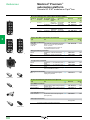
PCMCIA memory extension cards
Modicon® Premium™ processors can support up to 2 memory extension cards. However, useful memory capacity is limited to
the maximum size defined for the processor model. See pages1/22 and 1/23
6
Connection cables for PC programming terminal
Description
Universal cable for
terminal port/RS 232 port
Use
From terminal port
Mini-DIN (TER or AUX) on:
TSX Micro
Premium™ TSX P57 0p/1p
Premium TSX P57 2p/3p
Tap junction TSX P ACC 01
To PC
RS 232D port
(9-way SUB-D)
Length
Reference
2.5 m
TSX PCX 1031
Weight
kg
0.170
7
TSX PCX 1031
Cable for terminal port/
USB port
Mini-DIN (TER or AUX) on:
TSX Micro
Premium TSX P57 0p/1p
Premium TSX P57 2p/3p
Tap junction TSX P ACC 01
USB port
(USB/RS 485
converter)
0.4 m
TSX CUSB 485
(4)
0.144
USB port
(mini-DIN/RJ45
cable)
2.5 m
TSX CRJMD 25
(4)
0.150
USB (TER) on:
Premium TSX 57 4p/5p
Quantum™ 140 CPU 6p1
USB port on a PC
terminal
3.3 m
UNY XCA USB 033
8
–
9
TSX CUSB 485
(1) Product supplied with a multilingual Quick Reference Guide.
(2) Maximum number of TSX RKY 4EX/6EX/8EX racks (4, 6 or 8 slots). Using the TSX RKY 12 EX rack (12 slots) is the same
as using 2 racks with 4, 6 or 8 slots.
(3) Fieldbus: InterBus or Profibus DP.
(4) The TSX CUSB485 converter requires the use of cable TSX CRJMD 25 (length 2.5 m, equipped with1 mini-DIN connector
and 1 RJ45 connector).
1/13
10
Modicon® Premium™
automation platform
Presentation
0
PCMCIA memory extension cards
Unity™
Presentation
PCMCIA memory extension cards are used to extend the internal RAM capacity of
Modicon® Premium™ processors.
Some of the cards can also be used on Modicon® Quantum™ and Micro™ processors.
Depending on the model, these cards can host:
b Application program, symbols and constants
b Additional application data
b Or both
1
2
3
PCMCIA memory extension cards
The cards are inserted into PCMCIA slot no. 0 on Premium processors, i.e.:
b The upper slot on processors
b The internal slot on slot PLCs
Two of these SRAM data storage memory cards can also be inserted into slot no. 1,
i.e.:
b The lower slot on processors
b The external slot on slot PLCs
PCMCIA SRAM memory card
These cards support three types of data storage:
b Application storage: Program, symbols and constants in a common space (128 Kb
to 7168 Kb, depending on the card model):
v TSX™ MRP PpppK for SRAM memories
v TSX™ MFP PpppK/M for Flash EPROM memories
b Storage of the application and additional data, with 192 Kb to 7 Mb of application
space and 7 Mb to 0 Kb of data storage space for additional data. The limit between
these 2 spaces is configurable. The configurable cards are:
v TSX MRP CpppK/M for SRAM memories
v TSX™ MCP CpppK/M for Flash EPROM and SRAM memories
b Storage of additional data, provided by 4 Mb or 8 Mb TSX MRP F00pM SRAM
memory cards
4
PCMCIA Flash EPROM memory card
5
These cards use 2 technologies:
b Battery-backed SRAM
Used in particular in the creation and debugging phases for the application program.
These cards support:
v The application’s transfer and modification services in online mode
v Additional data storage
The memory is backed up by a removable battery integrated into the PCMCIA card.
A second auxiliary battery is present to enable the main battery to be replaced
without loss of data.
6
b Flash EPROM
Used once debugging of the application program is complete. It enables:
v Backup battery life restrictions to be overcome
v A global application transfer to be performed
If it is used, the application cannot be modified in online mode.
7
Program modification in online mode
Only extension cards on which the program is stored in SRAM memory
(TSX MRP PpppK/M and TSX MRP CpppK/M) support online program modification.
8
9
Users of processors fitted with memory extension cards who wish to modify or add
program data in online mode must follow the two recommendations below:
b Structure the application program in a number of sections of a reasonable size
b Where possible, select one of the two extension cards recommended in the table
below:
Modicon® Premium™ processors
TSX™ P57 0p
TSX P57 1p
Cards recommended for program modification TSX MRP PpppK TSX MRP
in online mode
and TSX MRP
P224K/P384K,
CpppK/M/7
TSX MRP
CpppK/M/7
10
1/14
TSX P57 2p
TSX P57 3p
TSX P57 4p
TSX P57 5p
TSX P57 6p
TSX PCI 57 2p TSX PCI 57 3p
TSX MRP CpppK/M/7
TSX MRP C002M, TSX MRP C003M,
TSX MRP C007M
Modicon® Premium™
automation platform
References
0
PCMCIA memory extension cards
Unity™
Memory capacities of processors and slot PLCs
Memory capacities without PCMCIA extension card (data, program, symbols, and constants in internal RAM memory):
Modicon® Premium™
TSX™ P57 TSX P57 TSX 57
TSX™ PCI TSX P57 TSX P57 TSX P57 TSX PCI TSX P57 TSX P57
processors
0244M
104/154M/ 204/
57 204M 254
304/
354M
57 354M 454/
554/
1634M
2634M
3634M
4634M
5634M
In internal RAM
96 Kb
160 Kb
192 Kb
208 Kb
440 Kb
1024 Kb
Memory capacities with PCMCIA extension card(s) (data in internal RAM memory; program, symbols, constants, and data storage on PCMCIA card):
Premium™ processors
TSX P57 TSX P57 TSX 57
TSX PCI TSX P57 TSX P57 TSX P57 TSX PCI TSX P57 TSX P57
0244M
104/154M/ 204/
57 204M 254
304/
354M
57 354M 454/
554/
1634M
2634M
3634M
4634M
5634M
Data in internal RAM
96 Kb
160 Kb
192 Kb
208 Kb
440 Kb
1024 Kb
PCMCIA extension (progr.,
128 Kb
224 Kb
768 Kb
768 Kb
1792 Kb
1792 Kb
2048 Kb
7168 Kb
symbols and constants)
Data storage on PCMCIA (1) 256 Kb
16,384 Kb, limited to 8192 Kb if the TSX MRP F008M PCMCIA card is used
TSX P57
6634M
1
2048 Kb
TSX P57
6634M
2048 Kb
7168 Kb
2
PCMCIA memory extension cards
Premium processors support the memory extension cards listed below. There are two types of memory limit:
- One associated with the type of processor or slot PLC (see above)
- One associated with the model of PCMCIA memory card selected
The lowest of these two limits defines the memory capacity available to the user for his/her application.
Use on processor
Slot
Memory size
Application
Reference
Additional data
SRAM application memory extensions
Slot 0
TSX™ P57 0p…57 4p
TSX™ PCI 57 2p/3p
3
Weight
kg
4
128 Kb
–
224 Kb
–
384 Kb
–
Configurable SRAM application/additional data memory extensions
TSX P57 0p…57 4p/PCI 57 2p/3p Slot 0
96…448 Kb
352…0 Kb
TSX 57 0p…57 6p
Slot 0
192…768 Kb
576…0 Kb
TSX PCI 57 2p/3p
192…1024 Kb
832…0 Kb
192…1792 Kb
1600…0 Kb
192…2048 Kb
1856…0 Kb
192…3072 Kb
2880…0 Kb
192…7168 Kb
6976…0 Kb
Flash EPROM application memory extensions
TSX P57 0p…57 4p
Slot 0
128 Kb
–
TSX PCI 57 2p/3p
224 Kb
–
384 Kb
–
TSX P57 0p…57 6p
Slot 0
512 Kb
–
TSX PCI 57 2p/3p
1024 Kb
–
TSX™ MRP P128K
TSX MRP P224K
TSX MRP P384K
0,076
0,076
0,076
TSX MRP C448K
TSX MRP C768K
TSX MRP C001M
TSX MRP C01M7
TSX MRP C002M
TSX MRP C003M
TSX MRP C007M
0,076
0,076
0,076
0,076
0,076
0,076
0,076
5
TSX™ MFP P128K
TSX MFP P224K
TSX MFP P384K
TSX MFP P512K
TSX MFP P001M
0,044
0,044
0,044
0,044
0,044
6
TSX P57 2p…57 6p
TSX PCI 57 2p/3p
TSX MFP P002M
TSX MFP P004M
0,044
0,044
TSX™ MCP C224K
0,076
TSX MCP C512K
TSX MCP C002M
0,076
0,076
TSX MRP F004M
TSX MRP F008M
0,076
0,076
TSX MFP B096K
0,044
Slot 0
2048 Kb
–
4096 Kb
–
Flash EPROM and SRAM application/additional data memory extensions
TSX P57 0p…57 4p
Slot 0
224 Kb
256 Kb
TSX PCI 57 2p/3p
TSX P57 0p…57 6p
Slot 0
512 Kb
512 Kb
TSX PCI 57 2p/3p
2048 Kb
1024 Kb
SRAM additional data memory extensions
TSX P57 2p…57 6p
Slot 0 or 1 –
4096 Kb
TSX PCI 57 2p/3p
(2)
8192 Kb
Flash EPROM backup card (3)
TSX 57 0p/1p
Slot 0
96 Kb
–
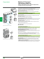
Handle to remove memory card for high-performance processors
Description
Use
Slot of processor
Handles
Remove PCMCIA memory card for No. 0 (upper slot)
(not provided with the memory card) TSX P57 4p…57 6p
No. 1 (lower slot)
Replacement parts
Description
Use
Type
Reference
TSX™ P CAPUP
TSX P CAPL
Reference
Main
TSX™ BAT M02 (4)
Auxiliary
TSX BAT M03
Handle
Remove PCMCIA memory card for –
TSX P CAP
(provided with the memory card)
TSX P57 0p…57 3p
(1) Intended for the storage of manufacturing recipes and production data. Capacity depending on PCMCIA card model.
(2) Memory extension card for file storage to be inserted into slot no. 0 if free, otherwise into slot no. 1. In the latter case, an
application memory type or application memory and file storage type memory extension card is inserted into slot no. 0.
(3) This card is pre-loaded and can be used to update the application program on a Premium PLC without having to use a
programming terminal (the entire program must be located in the internal RAM).
(4) TSX BAT M02 with PCMCIA card PV u 04 (blue), for PCMCIA card PV < 04, please order TSX BAT 01 reference.
Backup batteries
PCMCIA SRAM memory card
Weight
kg
0,012
0,012
Weight
kg
0.010
0 005
0.010
7
8
9
10
1/15
Selection guide
Modicon® Premium™
automation platform
0
Premium processors
PL7™
1
Modicon® Premium™ platforms for PL7™
software offer
TSX™ 57 1p processors
TSX 57 2p processors
Number of racks (according to rack type)
4 with 4, 6, or 8 slots or 2 with 12 slots
16 with 4, 6, or 8 slots or 8 with 12 slots
In-rack I/O (1)
512 channels (8-, 16-, 32- or 64-channel
modules)
24 channels (4-, 8- or 16- channel modules)
–
2
3
Discrete I/O
Analog I/O
Integrated process control
4
In-rack applicationspecific channels
Max. no. of channels
Counter
Motion (2)
Weighing
Serial links
5
Serial link connections Modbus®
Uni-Telway™
Character mode
6
Bus connections
Network connections
7
Network modules
Memory capacity
8
10
Without PCMCIA extension
With PCMCIA extension
Data storage
Symbol storage
Power supply
Premium processor
9
Actuator/sensor bus
AS-Interface® master V2
CANopen machine bus master
V4.02 (5)
InterBus® fieldbus master V2 (5)
or Profibus DP™ fieldbus master
V0 Class 1 and 2 (5)
Max. no. of networks
Ethernet
1024 channels (8-, 16-, 32- or 64-channel
modules)
80 channels (4-, 8- or 16- channel modules)
Configurable loops (10 channels with 3 loops
max.)
8
24
Modules with 2/4 counter channels 1 MHz max., single-channel electronic cam module
Modules with 1/2 axes for stepper motors, 2/3/4 axes for analog control servo motors, 8/16 axes
with SERCOS™ digital link
Module for 8 load cells (2 application-specific channels)
In-rack communication modules (1 application-specific channel)
RS 232, RS 485 or current loop (3) (4) master/slave PCMCIA modules and RS 485 master/
slave in-rack communication modules
1 integrated RS 485 master/slave channel, RS 232, RS 485 or current loop (3) (4) master/slave
PCMCIA modules and RS 485 master/slave in-rack communication modules
1 integrated RS 485 channel, RS 232, RS 485 or current loop (3) (4) PCMCIA modules and
RS 485 in-rack communication modules
2 in-rack modules
4 in-rack modules
1 PCMCIA module (3)
–
1 in-rack module
1
1
Multiprotocol in-rack modules (Modbus®/TCP, Uni-TE™, Global Data, I/O Scanning, TCP Open),
Web server, FactoryCast™ service and FactoryCast HMI services
Fipway® (3) (4) and Modbus Plus (3) PCMCIA modules, Ethway™ in-rack modules
32 Kwords program and data
32 Kwords data
64 Kwords program
128 Kwords
–
48/64 Kwords program and data (6)
48/64 Kwords data (6)
160 Kwords program
640 Kwords + 2048 Kwords
128 Kwords
100…240 V a, 24 V c non-isolated and 24…48 V c isolated power supply modules. A power
supply is required for each rack.
Standard
Integrated Ethernet
Integrated Fipio®
Integrated Ethernet and Fipio
TSX™ P57 103M
TSX P57 153M (7)
TSX P57 203M Q
TSX P57 2623M Q (8)
TSX P57 253M Q
TSX P57 2823M (8)
Pages
1/31
(1) The maximum values for the numbers of discrete I/O, analog I/O and process control channels are cumulative.
(2) 1 axis = 1 application-specific channel, except for SERCOS modules where, depending on the configuration, the module = 2…32 channels.
(3) Module to be inserted into the lower PCMCIA slot (no. 1) on the processor.
(4) Module to be inserted into the PCMCIA slot on the TSX SCY 21 601 in-rack communication module.
(5) Reduce the number of InterBus or Profibus DP modules permitted by 1 when CANopen is used.
(6) The second value corresponds to the processor with integrated Fipio bus manager link.
1/16
TSX™ 57 3p processors
0
TSX 57 4p processors
1
2
n
3
16 with 4, 6, or 8 slots or 8 with 12 slots
1024 channels (8-, 16-, 32- or 64-channel modules)
128 channels (4-, 8- or 16- channel modules)
Configurable loops (15 channels with 3 loops max.)
4
32
64
Modules with 2/4 counter channels 1 MHz max., single-channel electronic cam module
Modules with 1/2 axes for stepper motors, 2/3/4 axes for analog control servo motors, 8/16 axes with SERCOS digital link
Module for 8 load cells (2 application-specific channels)
In-rack communication modules (1 application-specific channel)
5
RS 232, RS 485 or current loop (3) (4) master/slave PCMCIA modules and RS 485 master/slave in-rack communication modules
1 integrated RS 485 master/slave channel, RS 232, RS 485 or current loop (3) (4) master/slave PCMCIA modules and RS 485 master/slave in-rack
communication modules
1 integrated RS 485 channel, RS 232, RS 485 or current loop (3) (4) PCMCIA modules and RS 485 in-rack communication modules
8 in-rack modules
6
1 PCMCIA module (3)
2 in-rack modules
3
4
Multiprotocol in-rack modules (Modbus®/TCP, Uni-TE™, Global Data, I/O Scanning, TCP Open), Web server, FactoryCast™ service and FactoryCast HMI services
Fipway® (3) (4) and Modbus Plus™ (3) PCMCIA modules, Ethway in-rack modules
64/80 Kwords program and data (6)
80/96 Kwords data (6)
384 Kwords program
640 Kwords + 2048 Kwords
128 Kwords
96 Kwords program and data
176 Kwords data
512 Kwords program (992 Kwords with PL7 V4.4 or higher)
2048 Kwords (640 Kwords + 2048 Kwords with PL7 V4.4 or higher)
256 Kwords (384 Kwords with PL7 V4.4 or higher)
8
100…240 V a, 24 V c non-isolated and 24…48 V c isolated power supply modules. A power supply is required for each rack.
TSX™ P57 353LAM (9)
TSX P57 303AM Q
TSX P57 3623AM Q (8)
TSX P57 353AM Q
TSX P57 453AM
1/31
(7) The TSX P57 153M processor does not support the CANopen bus PCMCIA module.
(8) The integrated Ethernet port requires one of the available network connections.
(9) Processor reserved for updating configuration with TSX P57 352M PL7 processor (old version)
7
9
TSX P57 4823AM (8)
Q Processor can be migrated from PL7 to Unity Pro by means of a simple update of the processor's operating system (included on the Unity Pro software CD-ROM).
n New feature
10
1/17
Presentation
Modicon® Premium™
automation platform
PL7™ processors
Presentation
1
Premium™ TSX™ P57 pp3M/3AM and TSX P57 pp23M/23AM automation platform
processors manage the entire PLC station, and are comprised of discrete I/O
modules, Preventa™ machine safety modules, analog I/O modules, and applicationspecific modules, that can be distributed over one or more racks connected via Bus X
or a fieldbus.
2
The types of processor available are divided into different capacities according to
memory, in-rack I/O, communication, and processing speed. According to the model:
b 4 to 16 racks
b 512 to 2040 discrete I/O
b 24 to 256 analog I/O
b 8 to 64 application-specific channels: Each application-specific module (counter,
motion control, serial link or weighing) accounts for 1 or a number of applicationspecific channels.
b 1 to 4 networks (Ethernet, Fipway®, Ethway™, Modbus Plus™), 2 to 8 AS‑Interface®
sensor/actuator buses, 1 to 2 fieldbuses (CANopen, InterBus®, Profibus DP™), 0 or 1
Fipio fieldbus, serial links (Modbus®, Uni-Telway™)
b 10 to 20 process control channels
TSX P57 processors
3
Integrated communication
4
According to the model, Premium processors include:
b A 10 or 100 Mbit/s Ethernet Modbus/TCP port (RJ45 connection)
b A 1 Mbit/s Fipio bus link (bus manager)
b Communication via 2 terminal ports (TER and AUX) using Uni-Telway or character
mode protocol (typically a 19 or 115 Kbit/s programming terminal and an operator
dialog terminal)
Each processor has a slot for a type III PCMCIA card that can accommodate a
network card (Fipway, Modbus Plus), bus (CANopen (1), Fipio Agent) or serial links
(Modbus, Uni-Telway, character mode).
5
Application design and installation
Different software licences are available for PL7™ Junior/Pro version V4.5 depending
on requirements:
b Single-station
b Multistation in the form of independent local stations (Junior/Pro), remote stations
connected to a server via a network (Pro OpenTeam for 3 to10 stations or
Pro OpenSite for more than 10 stations).
These licences are compatible with PC terminals running Windows 2000
Professional® or Windows XP® operating systems.
6
Configurations with TSX P57 351/352M processor
7
The TSX P57 353LAM single-format processor is intended as a replacement for the
old version TSX P57 351M/352M processors.
Migration of Modicon® Premium™ processors
Some Premium TSX P57 pp3M/3AM processors that are compatible with PL7
software can be migrated for compatibility with the Unity Pro™ software without the
need for hardware modifications. This migration from PL7 to Unity Pro is achieved by
means of the following software updates:
b Processor operating system
b Integrated Ethernet port operating system
This update is carried out using the OS-Loader tool, included in Unity Pro (see page
6/27). Once migrated, PL7 processors are equivalent to corresponding Unity
processors.
The following PL7 processors can be migrated to Unity Pro (software migration):
b TSX 57 2p: TSX P57 203/253/2623M become
TSX P57 204/254/2634M respectively.
b TSX 57 3p: TSX P57 303/353/3623AM become
TSX P7 304/354/3634M respectively (migration supported by Unity Pro version u 3.0).
8
9
Note: Processor migration requires the use of new PCMCIA TSX MRP P/C, TSX MFP P/C
memory references. See the equivalence table on page 1/32.
10
___________________________________________________________________________
(1) Not with TSX P57 153M processor.
1/18
Modicon® Premium™
automation platform
Presentation (continued),
description
PL7™ processors
Presentation (continued)
Migration of Modicon® Premium™ processors (continued)
Migration offers involving the replacement of the processor are available for other
product references. Please contact your Regional Schneider Electric Sales Office for
more information about these offers. They are only available for a limited period of time,
and include the following PL7™ processors:
b TSX™ P57 2823M for migration to TSX P57 254M with TSX ETY 4103 (1)
b TSX P57 453AM for migration to TSX P57 454M
b TSX P57 453AM for migration to TSX P57 554M
b TSX P57 4823AM for migration to TSX P57 4634M
b TSX P57 4823AM for migration to TSX P57 5634M
b TSX P57 4823AM for migration to TSX P57 454M with TSX ETY 4103 (1)
b TSX P57 4823AM for migration to TSX P57 554M with TSX ETY 4103 (1)
Description
1
2
3
4
Processors without integrated Ethernet port
5
6
7
TSX P57 353LAM
TSX P57 1p3M
1
2
3
4
5
6
7
TSX P57 2p3M TSX P573p3AM/453AM
Single-format TSX P57 1p3M/353LAM processors and double-format
TSX P57 2p3M/3p3AM/453AM processors feature the following on the front panel:
1 A display block with 5 LEDs:
v RUN LED (green): Processor in operation (program running)
v ERR LED (red): Controller detected fault on the processor or its on-board devices
(PCMCIA memory card and PCMCIA communication card)
v I/O LED (red): Controller detected fault occurring on another station module or
configuration fault
v TER LED (yellow): Activity on the terminal port
v FIP LED (red): Activity on the integrated Fipio bus
2 RESET button causing a cold restart of the PLC when it is activated
3 An 8-way female mini-DIN connector marked TER for connecting a programming
or adjustment terminal
4 An 8-way female mini-DIN connector marked AUX for connecting a peripheral
device
5 A PCMCIA slot (no. 0) for a memory extension card
6 A PCMCIA slot (no. 1) for a communication card or 4 Mb SRAM memory
extension card for storing additional data
7 A 9-way SUB-D connector (on TSX P57 153/253M, TSX P57 353 LAM and
TSX P57 353/453AM models) for Fipio bus manager communication
Processors with integrated Ethernet port
2
1
2
3
4
5
6
2
Double-format TSX P57 2623/2823M and TSX P57 3623AM/4823AM processors with
integrated Ethernet port feature the following on the front panel:
1 A display block with 5 LEDs:
v RUN LED (green): Processor in operation (program running)
v ERR LED (red): Controller detected fault on the processor or its on-board devices
3
4
(PCMCIA memory card and PCMCIA communication card)
5
v I/O LED (red): Controller detected fault occurring on another station module or
6
configuration fault
7
v TER LED (yellow): Activity on the terminal port
v FIP LED (red): Activity on the integrated Fipio bus
8
2 A display block relating to the integrated Ethernet port featuring 5 LEDs:
9
v RUN LED (green): Ethernet port ready
v ERR LED (red): Ethernet port inoperative
v COL LED (red): Collision detection
TSX P57 2623M
TSX P57 2823M
v STS LED (yellow): Ethernet link diagnostics
TSX P57 3623AM
TSX P57 4823AM
v Two TX and RX LEDs (yellow): Transmission/reception activity
3 RESET button causing a cold restart of the PLC when it is activated
4 An 8-way female mini-DIN connector marked TER for connecting a programming
or adjustment terminal
5 An 8-way female mini-DIN connector marked AUX for connecting a peripheral
device
6 An RJ45 connector for connection to the Ethernet network
7 A PCMCIA slot (no. 0) for a memory extension card
8 A PCMCIA slot (no. 1) for a communication card or 4 Mb SRAM memory
extension card for storing additional data
9 A 9-way SUB-D connector (on TSX P57 2823M/4823AM models) for Fipio bus
manager communication
________________________________________________________________________________________________________________________________
1
1
(1) The TSX ETY 4103 Ethernet Modbus/TCP module offered features the same functions as the integrated Ethernet port on TSX P57 2823M/4823AM processors.
However, the combined processor and Ethernet module use one slot more than the PL7 processor to be migrated. Therefore, this type of migration requires a
free slot in the Premium rack and modification of the converted Unity Pro application.
1/19
7
8
9
10
Modicon® Premium™
automation platform
Characteristics
PL7™ processors
1
Modicon® Premium™ PLCs have been developed to comply with major national and international standards on electronic industrial automation
equipment. See pages 9/8 to 9/19 “Standards, certification and environmental conditions”.
Characteristics and performance
Types of processor
TSX P57
103M
4
2
32
Maximum
No. of racks
configuration
2
4/6/8 slots
12 slots
Max. no. of slots for modules
Functions
3
4
Memories
5
Application
structure
6
7
Execution
time per
instruction
9
TSX P57
2623M
TSX P57
253M
TSX P57
2823M
Discrete I/O
512
1024
Analog I/O
24
80
Process control channels
–
10 (up to 30 simple loops)
Application-specific
8
24
channels, number
Application-specific
Counter, axis, weighing and serial links (Modbus®, Uni-Telway™ and asynchronous)
channels, type
Integrated
Ethernet
–
1
–
1
connections
–
1 (63 agents) –
1 (127 agents)
Fipio® manager
Serial link
1 link with 2 connectors (TER and AUX) 19.2 Kbit/s
1
1
1 integrated
1
1 integrated
Max. no. of
Networks (Ethernet,
Ethernet port
Ethernet port
connections
Fipway®, Modbus
Plus™, Ethway™)
AS-Interface® bus
2
4
CANopen bus
1
–
1
–
1, none if CANopen is used
InterBus® or
Profibus DP™ bus
Maximum
Without PCMCIA card
Kwords 32, program and data
48, program and data
64, program and data
capacity
With PCMCIA card
Kwords 64, program
160, program
160, program
32, data
48, data
64, data
Data storage
Kwords 128
2688
Maximum size Located internal bits
bits
4096
8132
of object zones (%Mi)
Located internal data
Kwords 30.5 for internal words %Mpi
32 for constant words %Kpi
Tasks
Master
1
1
Fast
1
1
Event
32 (1 has priority)
64 (1 has priority)
Without
PCMCIA card
No. of
Without
Kinstructions PCMCIA card
executed
every ms
With PCMCIA
card
System
overhead
TSX P57
203M
16
8
128
Max. no
in-rack
(1)
With PCMCIA
card
8
TSX P57
153M
Tasks
Boolean
On word or fixed-point
arithmetic
On floating points
Boolean
On word or fixed-point
arithmetic
On floating points
100% Boolean
65% Boolean and
35% fixed arithmetic
100% Boolean
65% Boolean and
35% fixed arithmetic
Master
Fast
ms
ms
0.50
0.62
0.19
0.25
ms
ms
ms
44
0.60
0.87
2.6
0.21
0.42
ms
Kinst/
ms
Kinst/
ms
Kinst/
ms
Kinst/
ms
ms
ms
44
1.52
2.6
4.76
1.05
3.57
1.18
3.70
0.85
2.50
1.50
0.80
3.10
1.00
0.35
1.2
(1) Only affects in-rack modules. The maximum values for the number of discrete I/O, analog I/O, application-specific channels, and process control channels are
cumulative. The remote I/O on the bus or network (CANopen, AS-Interface, Uni-Telway, Fipio, Modbus Plus, etc.) or fieldbus (InterBus or Profibus DP) are not
included in these maximum numbers.
10
1/20
Modicon® Premium™
automation platform
Characteristics (continued)
PL7™ processors
Modicon® Premium™ PLCs have been developed to comply with major national and international standards on electronic industrial automation
equipment. See pages 9/8 to 9/19 “Standards, certification and environmental conditions”.
Characteristics and performance (continued)
Types of processor
TSX™ P57
303AM
Maximum
No. of racks
configuration
Functions
4/6/8 slots
12 slots
Max. no. of slots for modules
16
8
128
Max. no
in-rack
(1)
1024
128
15 (up to 45 simple loops)
32
Integrated
connections
Max. no. of
connections
Memories
Maximum
capacity
Discrete I/O
Analog I/O
Process control channels
Application-specific
channels, number
Application-specific
channels, type
Ethernet
Fipio® manager
Serial link
Networks (Ethernet,
Fipway®, Modbus Plus™,
Ethway™)
AS-Interface® bus
CANopen bus
InterBus® or
Profibus DP™ bus
Without PCMCIA card
Kwords
With PCMCIA card
Data storage
Maximum size Located internal bits
of object zones (%Mi)
Located internal data
Application
structure
Task
Master
Fast
Event
Execution
time per
instruction
Without
PCMCIA card
Boolean
On word or fixed-point
arithmetic
On floating points
Boolean
On word or fixed-point
arithmetic
On floating points
100% Boolean
With PCMCIA
card
No. of
Without
Kinstructions PCMCIA card
executed
every ms
With PCMCIA
card
System
overhead
TSX P57
3623AM
Tasks
65% Boolean and 35%
fixed arithmetic
100% Boolean
65% Boolean and 35%
fixed arithmetic
Master
Fast
TSX
P57 353LAM
P57 353AM
TSX P57 453AM
TSX P57 4823AM
2
2040
256
20 (up to 60 simple loops)
64
3
Counter, axis, weighing and serial links (Modbus®, Uni-Telway™ and asynchronous)
–
1
–
–
1 (127 agents)
1 link with 2 connectors (TER and AUX) 19.2 or 115 Kbit/s
3
3 including
3
4
integrated
Ethernet port
8
1
2, 1 if CANopen is used
64, program and data
Kwords 384, program
80, data
Kwords 640 + 2048
bits
16,384
1
1
4 including
integrated
Ethernet port
80, program and 96, program and data
data
384, program
512/992 (2), program
96, data
176, data
2048/640 + 2048 (2)
32,768
4
5
Kwords 30.5 for internal words %Mpi
32 for constant words %Kpi
1
1
64 (1 has priority)
6
ms
ms
0.12
0.17
0.19/0.12 (3)
0.25/0.17 (3)
0.06
0.08
ms
ms
ms
2.5
0.17
0.33
2.6/2.5 (3)
0.21/0.17 (3)
0.42/0.33 (3)
1.7
0.06
0.08
ms
Kinst/
ms
Kinst/
ms
Kinst/
ms
Kinst/
ms
ms
ms
2.6
6.57
2.6/2.6 (3)
4.76/6.57 (3)
1.7
13.82
4.70
3.57/4.70 (3)
8.80
4.49
3.70/4.49 (3)
13.82
3.08
2.50/3.08 (3)
8.80
1.15
0.29
1.00/1.15 (3)
0.35/0.29 (3)
1.15
0.22
7
8
(1) Only affects in-rack modules. The maximum values for the number of discrete I/O, analog I/O, application-specific channels, and process control channels are
cumulative. The remote I/O on the bus or network (CANopen, AS-Interface, Uni-Telway, Fipio, Modbus Plus, etc.) or fieldbus (InterBus or Profibus DP) are not
included in these maximum numbers.
(2) The second value applies if PL7 Junior/Pro programming software V4.4 or higher is used.
(3) The first value applies to the single-format TSX P57 353LAM processor and the second to the double-format TSX P57 353AM processor.
9
10
1/21
Modicon® Premium™
automation platform
Functions,
references
Internal RAM
2
Program
Application data (30.5 Kwords max.)
Task descriptor and executable code
Constant words, initial values and configuration
30.5 Kwords
128/256
Kwords
128/640
Kwords
5
1
2
3
4
Data
Program
32 Kwords
PCMCIA card
(slot no. 0)
64 to 512 Kwords
4
32 to 176 Kwords
Processor with PCMCIA card
Internal RAM
6
Data
Constants
1
2
3
3
Memory structure
Processor without PCMCIA card
32 to 96 Kwords
1
PL7™ processors
Constants
Additional
data
storage
Symbols storage
Application data (30.5 Kwords max.)
Task descriptor and executable code
Constant words, initial values and configuration
Depending on the model of PCMCIA card
7
The application memory is divided into memory areas that are physically distributed
across the internal RAM memory and the PCMCIA memory extension card(s):
b The application data area is always in the internal RAM.
b The application program area is in the internal RAM or the PCMCIA memory card.
b The constants area is in the internal RAM or the PCMCIA memory card.
There are two ways of organizing the application memory for
TSX™ P57 1p3/2p3/2p23M and TSX P57 3p3/3623/453/4823AM processors with or
without a memory extension installed in the form of a PCMCIA format card:
Application in internal RAM
The application is completely loaded into the processor's battery-backed internal RAM (1).
The capacity depends on the processor model (32 to 96 Kwords).
For example, the TSX P57 1p3M processor has 7.5 Kwords of application data and
24.5 Kwords of program, constants and system data (2).
The memory space (32 Kwords) is shared between the application data, the
program, the constants and the system data (2).
Application in the PCMCIA card (slot no. 0)
The internal RAM is reserved for the application data.
The PCMCIA card contains the program and constants (64 to 512 Kwords).
The file storage area of 128 K or 640 Kwords (depending on the model of PCMCIA
card) can be used in remote applications, for storing production data information,
recipes, etc.
The symbols storage area of 128 K or 256 Kwords (depending on the model of
PCMCIA card) enables the application symbols database to be stored on the PLC.
Extension of the additional data storage area (slot no. 1)
This area, containing 128 or 640 Kwords, can be extended up to 2688 Kwords by using
an SRAM TSX MRP DS 2048P/MFP 004MPCMCIA memory card. This card is inserted
into the lower slot on TSX P57 2p3/2p23M, TSX P57 3p3/3623/453/4823AM processors
and can be used in conjunction with memory extension cards (type 1 in the upper slot).
Data in internal RAM
The data area can be extended to up to 30.5 Kwords. It is only supported by the
PLC's internal RAM.
PL7™ Junior/Pro software helps the application designer to manage the structure
and organize how the memory space on the Premium PLC is occupied.
Protecting the application
Regardless of the PLC memory structure (whether the application is located in the
internal RAM or on the PCMCIA card), it is possible to protect the application so that
it cannot be accessed (for the purpose of reading or modifying the program) in online
mode under PL7 Junior/Pro.
A memory protection bit, set in configuration mode, is also available to prevent any
program modification (via the programming terminal or downloading).
Modicon® Premium™ processor references
TSX 57 10/20/30/40 processors are equipped with:
b A PCMCIA slot (no. 0) that can accommodate a memory extension or SRAM
memory card for the purpose of storing additional data
b A PCMCIA slot (no. 1) that can accommodate a communication card or memory
card for the purpose of storing additional data
b Two terminal ports (8-way female mini-DIN type), Uni-Telway or character mode.
TSX 57 processors are double-format modules (except TSX P57 1p3M and
TSX P57 353LAM processors, which are single-format).
TSX 57 30/40 processors support the loading of programs, via the terminal port, at a
maximum speed of 115 Kbit/s (limited to 19.2 Kbit/s for TSX 57 10/20 processors).
The integrated Fipio® link (bus manager) on TSX 57 20/30/40 processors supports a
maximum of 127 connection points. The link on the TSX P57 153M processor is
limited to 63 connection points.
8
9
___________________________________________________________________________
(1) The internal RAM is protected by an optional battery with a life of 3 years. The battery is
located in the power supply module.
(2) The system has a minimum reserve RAM memory area in the order of 5 Kwords. Please refer
to the PL7 Micro/Junior/Pro reference manual.
10
1/22
References (continued)
Modicon® Premium™
automation platform
PL7™ processors
TSX™ 57 processors
I/O capacity (1)
Capacity
Memory
Control
channels
TSX 57 10 4 racks (2)
512 discrete I/O
32 Kwords
0
24 analog I/O 8 application- integrated
specific channels
64 Kwords max.
on PCMCIA
TSX P57 103M
TSX P57 153M
Maximum number
of bus/network
modules
Integrated
Port
Reference
Weight
kg
1 network
–
2 AS-Interface® buses
1 CANopen bus
–
1 integrated Fipio®
1 network
2 AS-Interface buses
TSX P57 103M
0.380
TSX P57 153M
0.420
1 network
–
4 AS-Interface buses
1 CANopen bus (3)
1 fieldbus (3)
4 AS-Interface buses 1 Ethernet
1 CANopen bus (3)
1 fieldbus (3)
TSX P57 203M
0.520
1
2
TSX 57 20 16 racks (2)
1024 discrete I/O
80 analog I/O
24 applicationspecific channels
TSX P57 203M
TSX P57
353LAM
48 Kwords
integrated
160 Kwords
max. on
PCMCIA
10
64 Kwords
integrated.
160 Kwords
max. on
PCMCIA
10
TSX P57 2623M
–
1 integrated Fipio
–
1 network
4 AS-Interface buses
1 CANopen bus (3)
1 fieldbus (3)
TSX P57 253M
1 integrated Fipio
1 Ethernet
4 AS-Interface buses
1 CANopen bus (3)
1 fieldbus (3)
TSX P57 2823M
–
3 networks
–
8 AS-Interface buses
1 CANopen bus (3)
2 fieldbuses (3)
2 networks
1 Ethernet
8 AS-Interface buses
1 CANopen bus (3)
2 fieldbuses (3)
TSX P57 303AM
0.520
3
0.560
4
TSX 57 30 16 racks (2)
1024 discrete I/O
128 analog I/O
32 applicationspecific channels
TSX P57 253M
TSX P57 353AM
TSX P57 453AM
64/80 Kwords
integrated (4)
384 Kwords
max. on
PCMCIA
15
80/96 Kwords
integrated (4)
384 Kwords
max. on
PCMCIA
15
1 integrated Fipio
3 networks
8 AS-Interface buses
1 CANopen bus (3)
2 fieldbuses (3)
–
TSX P57 3623AM
–
TSX P57 353LAM
(5)
TSX P57 353AM
(5)
0.420
TSX P57 453AM
0.560
0.560
TSX 57 40 16 racks (2)
2040 discrete I/O
256 analog I/O
64 applicationspecific channels
TSX P57 2623M
TSXP57 3623AM
TSX P57 2823M
TSX P57 4823AM
96/176 Kwords 20
integrated (4)
12/992 Kwords
max. (6) on
PCMCIA
1 integrated Fipio
–
4 networks (7)
8 AS-Interface buses
1 CANopen bus (3) 1 Ethernet
2 fieldbuses (3)
TSX P57 4823AM
5
6
7
–
PCMCIA memory extension cards
8
Premium processors can support up to 2 memory extension cards. However, useful memory capacity is limited to the
maximum size defined for the processor model.
References, see pages 1/32 and 1/33.
_________________________________________________________________________________________________
(1) Cumulative maximum values. The number of remote I/O on the bus is not included.
(2) Maximum number of TSX™ RKY 4EX/6EX/8EX racks (4, 6 or 8 slots). Using the TSX™ RKY 12EX rack (12 slots) is the
same as using 2 racks with 4, 6 or 8 slots.
(3) Using the CANopen bus reduces the number of possible fieldbuses (InterBus®/Profibus DP™) by 1.
(4) The second value corresponds to the integrated memory capacity when the processor is equipped with a PCMCIA
memory card.
(5) Single-format processor for TSX™ P57 353LAM, double-format processor for TSX P57 353AM.
(6) 992 Kwords with PL7 Junior/Pro software V4.4 or higher.
(7) 3 networks with TSX P57 4823AM processor.
1/23
9
10
Modicon® Premium™
automation platform
Presentation
0
PCMCIA memory extension cards
PL7™
Presentation
PCMCIA memory extension cards are used to extend the internal RAM capacity of
Premium processors. Depending on the model, these cards are designed to:
b Receive the application program and constants
b Store additional application data and/or various application object symbols
1
Mémoire PCMCIA Flash EPROM
Offer for Modicon® Premium™ platform under PL7™
As of November 2004, the old TSX™ MRP/MFP pppP PCMCIA memory extension
cards offer, which was specifically for Premium processors under PL7, was replaced
by a new offer. This offer includes (1):
b TSX Micro™ PLCs under PL7
b Premium processors under Unity™ Pro and PL7
b Modicon® Quantum™ processors under Unity Pro
The table below indicates equivalences between the old and new versions. There
may be one or more new references corresponding to each old reference depending
on whether migration from PL7 to Unity Pro is envisaged.
PCMCIA Flash EPROM memory
2
3
PCMCIA SRAM memory
SRAM memory extension (slot no. 0)
Use
4
5
All TSX 57 types
Max. memory size
PL7
Additional Symbol
application data
storage
Old reference
32 Kwords
–
–
128 Kwords –
–
–
TSX MRP 032P
TSX MRP 232P
TSX MRP 064P
128 Kwords –
TSX MRP 264P
64 Kwords
TSX 57 20
TSX 57 30
TSX 57 40
128 Kwords –
–
TSX MRP 0128P
128 Kwords 128 Kwords TSX MRP 2128P
256 Kwords –
6
–
TSX MRP 0256P
640 Kwords 128 Kwords TSX MRP 3256P
384 Kwords 640 Kwords –
TSX 57 40
7
512 Kwords –
TSX MRP 3384P
256 Kwords TSX MRP 0512P
992 Kwords 640 Kwords 384 Kwords –
Do you envisage migration from PL7 to
Unity Pro?
(P indicates “PL7 program”)
No
No
No
–
No
–
–
No
–
No
–
–
No
–
No
–
–
–
No
–
–
No
–
Yes
Yes
Yes, P < 52 Kwords
Yes, P > 52 Kwords
Yes (2)
Yes (2)
Yes, P < 64 Kwords
Yes, 64 Kwords < P < 104 Kwords
Yes, P > 104 Kwords
Yes (2)
Yes (2)
Yes, P < 104 Kwords
Yes, 128 Kwords < P < 208 Kwords
Yes, P > 208 Kwords
Yes
Yes (3)
Yes (4)
Yes (2)
Yes (2)
Yes, P < 256 Kwords
Yes, 256 Kwords < P < 384 Kwords
Yes, P > 384 Kwords
–
Recommended
reference
TSX MRP P128K
TSX MRP P384K
TSX MRP P224K
TSX MRP P384K
TSX MRP P384K
TSX MRP C768K
TSX MRP P384K
TSX MRP C448K
TSX MRP C768K
TSX MRP C768K
TSX MRP C01M7
TSX MRP C768K
TSX MRP C001M
TSX MRP C01M7
TSX MRP C01M7
TSX MRP C002M
TSX MRP C003M
TSX MRP C01M7
TSX MRP C002M
TSX MRP C01M7
TSX MRP C002M
TSX MRP C003M
TSX MRP C007M
Flash EPROM memory extension (slot no. 0)
All TSX 57 types
8
TSX 57 20
TSX 57 30
TSX 57 40
9
TSX MFP 264P
TSX MFP 0128P
No
No
No
No
–
No
No
Yes
Yes
No
Yes, P < 52 Kwords
Yes, P > 52 Kwords
Yes
No
TSX MFP P128K (5)
TSX MCP C224K (5)
TSX MFP 064P2 (1)
TSX MFP P224K (5)
TSX MFP P384K (5)
TSX MCP C224K (5)
TSX MFP 0128P2 (1)
–
–
No
No
Yes
Yes
TSX MFP P384K (5)
TSX MFP P001M (5)
–
TSX MRP DS 2048P
No
Yes
TSX MRP F004M
–
TSX MFP BAK 032P
No
Yes
TSX MFP B096K (4)
32 Kwords –
–
128 Kwords –
64 Kwords –
–
TSX MFP 032P
TSX MFP 232P
TSX MFP 064P
128 Kwords –
128 Kwords –
–
256 Kwords –
SRAM memory extension (slot no. 1)
TSX 57 20
TSX 57 30
TSX 57 40
–
2048
Kwords
Flash EPROM backup card (slot no. 0)
TSX 57 10
10
32 Kwords
–
(1) With the exception of TSX MFP 064P2/0128P2 Flash EPROM memory cards for use with PL7 processors.
(2) Selection based on the size of the PL7 program memory in relation to the size of the data storage memory.
(3) If symbols do not need to be stored on the PCMCIA.
(4) If additional data does not need to be stored on the PCMCIA.
(5) Memory card compatible with processor version u 5.5.
1/24
Presentation (continued),
references
Modicon® Premium™
automation platform
0
PCMCIA memory extension cards
PL7™
Presentation (continued)
PCMCIA memory extension cards
Memory cards (with the exception of TSX™ MRP P004M and TSX MRP DS 2048P for additional SRAM data storage) are
inserted into PCMCIA slot no. 0 on Modicon® Premium™ processors (upper slot). The TSX™ MRP F004M/TSX MRP DS 2048P
additional data storage card is inserted into slot no. 1 only on Premium processors (lower slot).
With PL7™, these cards support four different types of storage:
b Application storage: Program and constants in a common area of between 64 and 512 Kwords, in the SRAM or Flash
EPROM memory.
b Application and additional data storage, comprising an application area of between 64 and 384 Kwords and a data storage
area of 128 or 640 Kwords designed for additional data, in the SRAM or Flash EPROM and SRAM.
b Application, additional data and symbol storage, comprising an application area of between 32 and 512 Kwords, a data
storage area of 128 or 640 Kwords designed for additional data, and a symbols area of 128 or 256 Kwords, in the SRAM or
Flash EPROM and SRAM.
b Additional data storage provided by an SRAM with a capacity of 2 M words.
These cards use 2 technologies:
b Battery-backed SRAM. Used in particular in the creation and debugging phases for the application program. These cards
support application transfer and modification services in online mode and the storage of additional data.
The memory is backed up by a removable battery integrated into the PCMCIA card. A second, auxiliary battery, provides
backup so that the main battery can be replaced without data being lost.
b Flash EPROM. Used once debugging of the application program is complete. It enables restrictions in terms of the service life
of backup batteries to be avoided and supports global application transfer. If a Flash EPROM is used, the application cannot be
modified in online mode.
References
If future migration from PL7™ to Unity™ Pro is envisaged, see the equivalence table opposite for the new equivalent reference.
1
2
3
4
SRAM memory extension (slot no. 0)
Use
TSX™ 57 10…40
TSX 57 20…40
TSX 57 40
Max. memory size
PL7
Additional Symbol
application data
storage
Old reference
TSX 57 20…40
32 Kwords –
–
TSX MRP 032P
TSX™ MRP P128K
0.076
64 Kwords –
128 Kwords
128 Kwords –
128 Kwords
256 Kwords –
640 Kwords
384 Kwords 640 Kwords
512 Kwords –
992 Kwords 640 Kwords
–
–
–
128 Kwords
–
128 Kwords
–
256 Kwords
384 Kwords
TSX MRP 064P
TSX MRP 232P/264P
TSX MRP 0128P
TSX MRP 2128P
TSX MRP 0256P
TSX MRP 3256P
TSX MRP 3384P
TSX MRP 0512P
–
TSX MRP P224K
TSX MRP P384K
TSX MRP C448K
TSX MRP C768K
TSX MRP C001M
TSX MRP C01M7
TSX MRP C002M
TSX MRP C003M
TSX MRP C007M
0.076
0.076
0.076
0.076
0.076
0.076
0.076
0.076
0.076
32 Kwords
–
–
TSX MFP 032P
TSX™ MFP P128K (1)
0.044
64 Kwords
–
–
128 Kwords
–
–
–
–
–
–
–
–
–
TSX MFP 064P
TSX MFP 064P
TSX MFP 232P/264P
TSX MFP 0128P
TSX MFP 0128P
–
TSX MFP P224K (1)
TSX MFP 064P2 (2)
TSX MCP C224K (1)
TSX MFP P384K (1)
TSX MFP 0128P2 (2)
TSX MFP P001M (1)
0.044
0.044
0.044
0.044
0.044
0.044
TSX MRP DS 2048P
TSX MRP F004M
0.076
TSX MFP BAK 032P
TSX MFP B096K (1)
0.044
Type
Reference
128 Kwords
256 Kwords
Flash SRAM memory extension (slot no. 1)
TSX 57 20…40
Weight
kg
Flash EPROM memory extension (slot no. 0)
TSX 57 10…40
Reference
–
2048 Kwords –
Flash EPROM backup card (slot no. 0)
TSX 57 10
32 Kwords –
–
5
6
7
8
Replacement parts
Description
Backup batteries
Handle
Use
PCMCIA SRAM memory cards
Main battery
Auxiliary battery
Removal of PCMCIA memory card –
(provided with the memory card)
TSX™ BAT M02 (3)
TSX BAT M03 (4)
TSX™ P CAP
Weight
kg
0.010
0.05
0.010
(1) Memory card (blue) compatible with processor version u 5.5.
(2) Memory card (orange) only compatible in run mode (no backup facility) with processor version y 5.0 and < 6.1 compatible
with processor version u 6.1. Memory card designed for PL7 processors.
(3) For the SRAM memory card with the old reference TSX MRP pppP or with the new reference PV < 04 (green), quote order
reference number TSX BAT M01.
(4) Only for SRAM memory cards with a new reference.
1/25
9
10
1
2
3
4
5
6
7
8
9
10
1/26
2/0
Contents chapter 2
Racks, I/O architectures
and power supplies
2
2.1 - Power supply and fan modules
b Description�������������������������������������������������������������������������������������������������������� 2/2
b Characteristics�������������������������������������������������������������������������������������������������� 2/3
1
b Functions���������������������������������������������������������������������������������������������������������� 2/4
b References ������������������������������������������������������������������������������������������������������ 2/5
b Dimensions and mounting�������������������������������������������������������������������������������� 2/5
2
2.2 - Single rack configuration
b Presentation,description ���������������������������������������������������������������������������������� 2/6
b References ������������������������������������������������������������������������������������������������������ 2/6
b Dimensions and mounting�������������������������������������������������������������������������������� 2/7
3
2.3 - Multi-racks configuration without remote module
b Presentation����������������������������������������������������������������������������������������������������� 2/8
b Description�������������������������������������������������������������������������������������������������������� 2/9
b Rack addresses������������������������������������������������������������������������������������������������ 2/9
4
b References ���������������������������������������������������������������������������������������������������� 2/10
b Dimensions and mounting������������������������������������������������������������������������������� 2/11
2.4 - Multi-racks configuration with remote module
5
b Presentation��������������������������������������������������������������������������������������������������� 2/12
b Description������������������������������������������������������������������������������������������������������ 2/13
b References ���������������������������������������������������������������������������������������������������� 2/13
6
7
8
9
10
2/1
Modicon® Premium™
automation platform
Description
Power supply and fan modules
Description of power supply modules
1
1
TSX™ PSYppp0M power supply modules provide the power supply for each rack
and the modules installed on it.
2
3
The power supply module is selected according to:
b The mains electrical supply: c 24 V, c 24...48 V, a 100...120, a 200...240 V
b The required power: standard format or double format model, see power
consumption table on page 9/6.
4
2
5
7
TSX PSYppp0M power supply modules are comprised of:
1 Display block comprising:
v OK lamp (green), on if voltages are present and correct.
v BAT lamp (red), on if the battery is inoperative or missing.
v 24 V lamp (green), on when the sensor voltage is present (according to model).
2 RESET pencil-point pushbutton causing a warm restart of the application.
3 Slot for a battery that protects the internal RAM memory of the processor.
4 Cover to protect the front panel of the module.
5 Screw terminal for connecting:
v To mains supply.
v The alarm relay contact.
v The sensor power supply for a.c. supplies (according to model).
6 Opening for cable clamp.
7 Fuse located beneath the module and protecting:
v 24 VR voltage on the non-isolated d.c. supply with TSX PSY 3610.
v Primary voltage on the other power supplies.
8 110/220 voltage selector (according to model).
6
TSX PSY 2600M
3
8
1
2
3
4
4
5
5
7
6
Description of fan modules
TSX PSY 5500M
TSX™ FAN ppP fan modules installed above the racks of Modicon® Premium™ PLCs
provide forced air convection, in order to maintain an even ambient temperature
inside the enclosure and to eliminate the various hot spots that may exist.
Fan modules are required whenever the ambient temperature is between 60 °C and
70 °C (forced ventilation enables the ambient temperature in the enclosure to be
lowered by 10 °C) (1).
Three types of fan module are available: c 24 V, a 110 V and a 220 V.
6
7
According to the modularity of the racks used:
b One fan module for a 4 or 6 position rack,
b Two fan modules for an 8 position rack,
b Three fan modules for a 12 position rack.
3
3
1
4
2
8
TSX FAN ppP fan modules are comprised of:
1 Connection terminal for the fan module power supply, the internal temperature
probe and the associated LED or preactuator.
2 Ground terminal.
3 Two mounting holes for the fan module.
4 Shuttered air outlets.
__________________________________________________________________
(1) For an ambient temperature between 25 °C and 60 °C, the use of fan modules increases the
MTBF.
9
10
2/2
Modicon® Premium™
automation platform
Characteristics
Power supply and fan modules
Characteristics
Type of power supply module
Primary
Voltage
Nominal
Limit (ripple included)
Frequency
Currency
Nominal/limit
Nominal input
Initial start up 1 inrush
at 25 °C (2)
I²t on activation
It on activation
Duration of Main supply (accepted)
micro breaks
Integrated protection
Secondary
Power
Total useful (typical)
Output c 5 V Nominal voltage
Nominal current
Power (typical)
Output
Nominal voltage
c 24 VR (3) Nominal current
Power (typical)
Output c 24 V sensors
Integrated protection on outputs (4)
Conformity to standards
Isolation
Dielectric
Primary/secondary and
withstand
primary/ground
Insulation
Primary/secondary and
resistance
primary/ground
Type od power supply module
Primary
Voltage
Nominal
Limit (ripple included)
Frequencys Nominal/limit
Current
Nominal input
Initial start up I inrush current
at 25 °C
(2)
I²t on activation
It on activation
Duration of
Mains supply (accepted)
micro breaks
Integrated protection
Secondary Power
Total useful (typical)
Output c 5 V Nominal voltage
Nominal current
Power (typical)
Output
Nominal voltage
c 24 VR (3) Nominal current
Power (typical)
Output
Sensors
c 24 VC
Integrated protection on outputs (4)
Conformity to standards
Isolation
Dielectric
Primary/secondary and
withstand
primary/ground
Insulation
Primary/secondary and
resistance
primary/ground
Hz
A rms
TSX PSY 1610M
TSX PSY 3610M
c 24
c 24
c 19.2...30 (1)
(possible up to 34 V for 1 h in evry 24 h)
–
–
≤ 1.5 at c 24 V
≤ 2.7 at c 24 V
A
100 at c 24 V
150 at c 24 V
A ²s
12.5
20
As
0.2
0.5
ms
≤1
≤1
V
V
TSX PSY 5520M
c 24...48
c 19.2...60
1
–
≤ 3 at c 24 V
≤ 1.5 at c 48 V
15 at c 24 V
15 at c 48 V
50 at c 24 V
55 at c 48 V
7 at c 24 V
6 at c 48 V
≤1
2
By fuse 5 x 20,
time-delayed 5 A
50
5
7
35
24
0.8
19
–
V eff
By fuse 5 x 20,
No
time-delayed 3.5 A
30
50
5
5
3
7
15
35
U mains - 0.6
U mains - 0.6
0.6
0.6
15
19
–
–
Yes, against overloads, short-circuits and overvoltages
IEC 61131-2
Non isolated, internal 0 V connected to PLC ground
MW
–
≥ 10
W
V
A
W
V
A
W
ms
W
V
A
W
V
A
W
A
By fuse 5 x 20, time-delayed, 4 A
26
50
5
5
5
7
25
35
24
24
0.6
0.8
15
19
0.5
0.8
77 (5)
5
15
75
–
–
–
1.6 (TBTS)
V eff
Yes, against overloads, short-circuits and overvoltages
IEC 61131-2
2000 - 50/60 Hz - 1 min
3000 - 50/60 Hz - 1 min
MW
≥ 100
A
A²s
As
4
2000 - 50/60 Hz - 1 min
TSX PSY 2600M
a 100...240
a 85...264
50…60/47…63
0.5 at a 100 V
0.3 at a 240 V
37 at a 100 V
75 at a 240 V
0.63 at a 100 V
2.6 at a 240 V
0.034 at a 100 V
0.067 at a 240 V
≤ 10
V
V
Hz
A rms
3
TSX PSY 5500M
a 100...120/200...240
a 85...140/190...264
a 85...140/170...264
1.7 at a 100 V
0.5 at a 240 V
38 at a 100 V
38 at a 240 V
4 at a 100 V
2 at a 240 V
0.11 at a 100 V
0.11 at a 240 V
≤ 10
1.7 at a 100 V
0.5 at a 240 V
30 at a 100 V
60 at a 240 V
15 at a 100 V
8 at a 240 V
0.15 at a 100 V
0.15 at a 240 V
≤ 10
5
TSX PSY 8500M
6
7
8
9
(1) When supplying modules with relay outputs, the range is reduced to 21.6…26.4 V.
(2) These values should be taken into account when starting several devices simultaneously and
for sizing protection devices.
(3) Output c 24 V for supplying relays of modules with relay outputs.
(4) Output c 24 VR, cannot be accessed by the user and is protected by a fuse located beneath
the module (5 x 20, 4 A, type Medium)
(5) 77 W at 60 °C, 85 W at 55 °C, or 100 W at 55 °C using TSX FANppP fan modules.
2/3
10
Functions
Modicon® Premium™
automation platform
Power supply and fan modules
Functions
Alarm relay
1
The alarm relay located in each power supply module has a volt-free contact that
can be accessed on the connection screw terminal of the module.
2
The operating principle is as follows:
b Module alarm relay located on the processor rack (rack 0): in normal operation,
PLC in RUN, the alarm relay is activated and its contact is closed (state 1). Whenever
the application stops, even partially:
v occurrence of a blocking condition
v incorrect output voltages
v loss of mains power,
the relay de-energizes and the associated contact opens (state 0).
3
b Alarm relay of power supply modules located on other racks (racks 1 to 7): when
the module is powered up and if the output voltages are correct, the relay is activated
and its contact is closed (state 1). When the mains power is lost or if the output
voltages are incorrect, the relay de-energizes (state 0).
Back-up battery
Each power supply module has a slot reserved for a battery that provides the power
supply to the internal RAM memory located in the processors, in order to help ensure
that data is saved when the PLC is switched off. The duration of data back-up is one
year. The battery must be changed as soon as the BAT lamp (red) on the front panel
lights up.
4
RESET pushbutton
Pressing this pushbutton, on the front panel of the power supply module, triggers a
sequence of service signals that is the same for:
b A power break when the pushbutton is pressed
b A power up when the pushbutton is released
5
These operations are expressed by the application as a warm restart.
6
Sensor power supply c 24 V
The TSX™ PSY 2600M/5500M/8500M a.c. power supply modules have an
integrated power supply that provides a voltage of c 24 V to supply the input
sensors. Connection to this sensor power supply can be accessed via the module
screw terminal. The available power on c 24 V depends on model (0,5/0,8/1,6 A),
see characteristics page 2/3.
7
8
9
10
2/4
Modicon® Premium™
automation platform
References,
dimensions,
mounting
Power supply and fan modules
References
Each TSX™ RKY p/pEX rack must be equipped with a single or double format power supply
module (slot marked PS).
The power required to supply each TSX RKY rack depends on the type and number of modules
installed in the rack. It is therefore necessary to establish a power consumption table rack by rack
in order to determine the TSX PSY power supply module most suitable for each rack (see pages
9/6 and 9/7).
Power supply module
Power
supply
Available power (1)
c5V
c 24 VR c 24 VC Total
15 W
15 W
–
30 W
35 W
19 W
–
50 W
Standard TSX PSY 1610M
Double
TSX PSY 3610M
0.540
0.780
35 W
19 W
–
50 W
Double
TSX PSY 5520M
0.890
a 100…240 V 25 W
15 W
12 W
26 W
Standard TSX PSY 2600M
0.510
a 100…120 V 35 W
a 200…240 V 75 W
19 W
–
19 W
38 W
(SELV)
50 W
77 W
Double
Double
TSX PSY 5500M
TSX PSY 8500M
0.620
0.740
c 24 V non
isolated (3)
c 24...48 V
isolated
TSX PSY 2600M
Format
Reference
(2)
Weight
kg
Accessories
Description Use
Battery
TSX PSY 5500M
Quantity Reference
Internal RAM memory backup (position 1 battery
in power supply modules)
10
batteries
TSX PLP 01
TSX PLP 101
Weight
kg
0.010
0.100
Fan modules
Description Use
Fan modules For TSX RKY p or
(4)
TSX RKY pEX racks
TSX FAN ppP
Power supply
Reference
c 24 V
a 100…120 V
a 200…240 V
TSX™ FAN D2P
TSX FAN A4P
TSX FAN A5P
Weight
kg
0.500
0.500
0.500
(1) Voltages c 5 V and c 24 VR for power supply to Premium modules, voltage c 24 VC for
supplying power to input sensors. The sum of absorbed power on each voltage (c 5 V,
c 24 VR and c 24 VC) should not exceed the total power of the module. See power
consumption table on page 9/6.
(2) Product supplied with a processor RAM memory backup battery.
(3) The internal 0 V of the module is connected to the PLC ground.
(4) One fan module for rack with 4 or 6 positions, two fan modules for rack with 8 positions and
three fan modules for rack with 12 positions. Product supplied with bilingual Quick Reference
Guide: English and French.
1
2
3
4
5
6
7
Dimensions/mounting TSX FAN pP
Side view
Front view
Fan module mounting
8
9
10
2/5
Modicon® Premium™
automation platform
Presentation,
description,
references
0
Single rack configuration
Presentation
TSX™ RKY pp racks form the basic elements of the Premium control system
platform with a single rack (6, 8 or 12 positions).
1
These non extandable racks provide the following functions:
b Mechanical function: they enable the modules of a PLC station (power supply,
processor, discrete I/O, analog I/O, application-specific modules) to be fitted.
b Electrical function: they enable connection to the bus (bus X) and provide
distribution of: They enable connection to:
v power supplies required for each module in the same rack,
v data and service signals for the entire PLC station where this has several racks.
2
TSX™ FAN ppP fan modules installed above the racks of Premium PLCs provide
forced air convection, in order to maintain an even ambient temperature inside the
enclosure and to eliminate the various hot spots that may exist (see page 2/2).
3
4
Description
1
5
9
5
8
3
7
6
4
2
6
TSX RKY pp non-extendable racks are comprised of:
1 Metal frame.
2 Slots for anchoring the module pins.
3 48-way female 1/2 DIN connectors for module-rack connections (the first
connector is reserved for the power supply module).
4 Locating slot for the power supply module.
5 Tapped holes for fixing the module.
6 Four holes for mounting the rack.
7 Position for rack address label.
8 Position for station network address label.
9 Two ground terminals for grounding the rack.
References
Non-extendable racks
Description
7
8
Non-extendable
racks,
for single rack
configuration
Type of modules to be
Capacity
installed
TSX PSY power supply,
6 positions
TSX P57 processor,
8 positions
TSX H57 processor
12 positions
I/O modules,
application-specific modules
Reference
TSX RKY 6 (1)
TSX RKY 8 (1)
TSX RKY 12
Weight
kg
1.470
1.750
2.310
TSX RKY 6
Connection accessories
Description
Use
Protective covers Unoccupied position on
TSX RKY p or
TSX RKY pEX racks
Mounting screws Mounting for
M6 x 25
TSX RKY p or
TSX RKY pEX racks
9
Comprising
Unit reference
5 screw-on
TSX™ RKA 02
covers
(Sold in lots of 5)
Captive screw
TSX™ ACC VA625
and washer with
hexagonal slotted
head
(Sold in lots of 50)
Weight
kg
0.050
0.350
(1) In the case where the limits of electromagnetic emissions between 30 MHz and 1 GHz must
be supervised, it is recommended to use the TSX RKY 6EX/8EX extendable racks instead of
the TSX RKY 6/8 non-extendable racks, dee page 2/10.
10
2/6
Dimensions,
mounting
Modicon® Premium™
automation platform
0
Single rack configuration
Dimensions, mounting
TSX™ RKY
Common side view
1
Front view : TSX RKY 6 exemple
TSX RKY 6
TSX RKY 8
TSX RKY 12
a
261.6
335.3
482.6
(1) With screw terminal block
(2) With HE 10 or SUB-D type connectors
2
on AM1 ED profiles
3
Mounting of racks
on AM1 PA perforated plate
4 holes (1)
4
5
a
b
TSX RKY 6
261.6
244.1
TSX RKY 8
335.3
317.8
TSX RKY 12
482.6
465.1
(1) For mounting on panel: the diameter of the holes must accommodate an M6 screw
6
Installation rules
7
8
9
a ≥ 50 mm
(1) Equipment or enclosure
10
(2) Cable ducting or clip
(3) ≥ 130 mm with TSX FAN ppP fan module
(4) TSX RKY 6: 1 fan module per rack
TSX RKY 8: 2 fan modules per rack
TSX RKY 12: 3 fan modules per rack
2/7
Presentation
Modicon® Premium™
automation platform
Multi-racks configuration without remote module
Composition of a PLC station
1
Using 1 TSX™ RKY 4EX/6EX/8EX/12EX (1) extendable racks, a PLC station can be
constituted which is comprised of up to:
b 4 racks for a station with TSX 57 10 Premium™ processor,
b 16 racks for a station with TSX 57 20, 57 30, 57 40, 57 50 Premium™ processor.
The racks are connected to each other by bus X extension cables 2.
2
The racks distributed on bus X are connected to each other via bus X extension
cables whose total length is 100 m maximum. Using TSX REY 200 bus X remote
modules enables the length of bus X to be increased to a maximum of 2 x 350 m (see
2/12).
The racks are connected to each other using TSX CBY pp0K bus X extension cables
which are connected to one of the two 9-way SUB-D connectors on each extendable
rack. The incoming cable from another rack can be connected to either the right 4 or
left-hand 3 connector.
Bus X
3
Line terminations
The two extendable racks located at the ends of the line must have a TSX TLY EX
line terminator 5 fitted on the unused 9-way SUB-D type connector.
Presentation of extentable racks
4
TSX RKY ppEX racks form the basic elements of the Modicon® Premium™ control
system platform. These racks provide the following functions:
b Mechanical function: they enable the modules of a PLC station (power supply,
processor, discrete I/O, analog I/O, application-specific modules) to be fitted.
b Electrical function: they enable connection to the bus (bus X) and provide
distribution of:
v power supplies required for each module in the same rack,
v data and service signals for the entire PLC station where this has several racks.
5
To meet user requirements, several types of rack are available in order to make up
PLC stations comprising 1 to 16 racks maximum distributed over bus X with a
maximum cumulative length of 100 meters.
TSX FAN ppP fan modules installed above the racks of Premium PLCs provide
forced air convection, in order to maintain an even ambient temperature inside the
enclosure and to eliminate the various hot spots that may exist (see page 2/2).
6
7
__________________________________________________________________
(1) Using the TSX RKY 12EX (12 slots) is the same as occupying 2 racks with 4, 6 or 8 slots.
8
9
10
2/8
Modicon® Premium™
automation platform
Description,
functions
Multi-racks configuration without remote module
Description
1
5
10
9
8
3
11
11
7
6
4
2
“less-significant”
00
01
02
03
04
05
06
07
8
9
1
2
3
Rack addresses
“most-significant”
Address rack n, example with 2 racks 6 slots, standard format
power supply and standard format processor
PS
TSX™ RKY ppp racks are comprised of:
1 Metal frame.
2 Slots for anchoring the module pins.
3 48-way female 1/2 DIN connectors for module-rack connections (the first
connector is reserved for the power supply module).
4 Locating slot for the power supply module.
5 Tapped holes for Mounting the module.
6 Four holes for mounting the rack.
7 Position for rack address label.
8 Position for station network address label.
9 Two ground terminals for grounding the rack.
10 Microswitches for coding the rack address (on extendable racks).
11 Two 9-way female SUB-D connectors for the remote connection of bus X to
another extendable rack.
10
Address rack n, example with 1 rack 12 slots, standard format
power supply and standard format processor
Principal rack
address 0 with
standard format
power supply and
standard format
processor
Principal rack
address 0 with
double format
power supply and
standard format
processor
Extension rack
address n with
standard format
power supply
Address 0: this address is always assigned to the rack which holds the processor.
This rack can be located in any position on the line.
Addresses 1 to 7: these can be assigned in any order to the other extendable racks
of the station.
As the two racks with 4,6, or 8 slots which make up each pair can have the same
address on the bus X, position numbers are defined as follows:
b Rack n “less-significant”: position 00 to xx (02, 04 or 06); rack n “most-significant”:
position 08 to yy (10, 12 or 14).
b Each rack with 12 slots holds an address (with position 00 to 10).
Installing the various modules on the standard or extendable rack with address 0
The rack with address 0 must contain a power supply module and the processor
module. For Modicon® Premium™ PLCs which have two types of power supply
(standard or double format), the position of the processor (standard or double
format) will depend on the type of power supply used.
Using a standard format power supply module:
b The power supply module systematically occupies position PS.
b The processor module must be installed in position 00/01 (00 with standard
format processor).
b The other modules are installed from position 02 (01 with standard format
processor).
Using a double format power supply module:
b The power supply module systematically occupies positions PS and 00.
b The processor module must be installed in position 01/02 (01 with standard format
processor).
b The other modules are installed from position 03 (02 with standard format
processor).
Installing the various modules on extendable racks with addresses 1 to 7
4
5
6
7
8
Each rack must have either a standard format or double format power supply
module.
Using a standard format power supply module:
b The power supply module systematically occupies position PS.
b The other modules are installed from position 00 onwards.
Using a double format power supply module:
b The power supply module systematically occupies positions PS and 00.
b The other modules are installed from position 01 onwards.
9
Extension rack
address n with
double format power
supply
10
2/9
Modicon® Premium™
automation platform
References
Multi-racks configuration without remote module
Extendable racks
Description
1
2
Extendable racks
for multi-racks
configuration
(max. 16 racks)
(1)
TSX RKY 6EX
4
5
6
Reference
TSX™ PSY power supply,
TSX™ P57 or TSX H57 processor (main rack)
I/O modules
Application-specific modules
Communication modules
4 positions
6 positions
8 positions
12 positions
TSX™ RKY 4EX
TSX RKY 6EX
TSX RKY 8EX
TSX RKY 12EX
Weight
kg
1.160
1.500
1.780
2.340
Use
Comprising
Length
Reference
Daisy chaining
cables
Bus X (total length
100 m max.)
(2)
Between
TSX RKY pEX racks
2 x 9-way SUB-D
connectors
1m
3m
5m
12 m
18 m
28 m
38 m
50 m
72 m
100 m
TSX™ CBY 010K
TSX CBY 030K
TSX CBY 050K
TSX CBY 120K
TSX CBY 180K
TSX CBY 280K
TSX CBY 380K
TSX CBY 500K
TSX CBY 720K
TSX CBY 1000K
Cable on reel
Length to be fitted with Cable with free ends, 100 m
TSX CBY K9
2 line testers
connectors
TSX CBY 1000
Bus X connectors
For TSX CBY 1000
cable ends
2 x 9-way SUB-D
connectors
Sold in lots of 2
TSX CBY K9
0.080
Line terminators
Compulsory on the
2 TSX RKY pEX end
racks
2 x 9-way SUB-D
connectors labelled
A and B
Sold in lots of 2
TSX™ TLY EX
0.050
Protective covers
Unoccupied position
on TSX RKY p or
TSX RKY pEX racks
5 screw-on covers
Sold in lots of 5
TSX™ RKA 02
0.050
Installation of
connectors
Mounting of
TSX CBY K9
connectors
2 crimping pliers,
1 pen (3)
–
TSX™ CBY ACC 10
Mounting screws
M6 x 25
Mounting for
TSX RKY p or
TSX RKY pEX racks
Captive screw and
washer with
hexagonal slotted
head
Sold in lots of 50
TSX™ ACC VA625
TSX TLY EX
7
Capacity
Connection accessories
Description
3
Type of modules to be installed
Weight
kg
0.160
0.260
0.360
1.260
1.860
2.860
3.860
5.060
7.260
10.060
(1) 16 racks TSX RKY 4EX/6EX/8EX max. (4, 6 or 8 slots) or 8 racks TSX RKY 12EX max. (12 slots). Using the
TSX RKY 12EX (12 slots) is the same as occupying 2 racks with 4, 6 or 8 slots.
(2) 2 x 350 m maximum when using the TSX REY 200 bus X remote module (see page 2/12).
(3) Installation of connectors on the cable also requires a wire stripper, a pair of scissors and a digital ohmmeter.
8
9
10
2/10
12.320
–
0.350
Dimensions,
mounting
Modicon® Premium™
automation platform
Multi-racks configuration without remote module
Dimensions, mounting
TSX™ RKY
Common side view
1
Front view : TSX RKY 6EX example
TSX RKY 4EX
TSX RKY 6EX
TSX RKY 8EX
TSX RKY 12EX
a
187.9
261.6
335.3
482.6
2
(1) With screw terminal block
(2) With HE 10 or SUB-D type connectors
Mounting of racks
on AM1 PA perforated plate
3
On AM1 ED profiles
4 holes (1)
4
a
b
TSX RKY 4EX
187.9
170.4
TSX RKY 6EX
261.6
244.1
TSX RKY 8EX
335.3
317.8
TSX RKY 12EX
482.6
465.1
(1) For mounting on panel: the diameter of the holes must accommodate an M6 screw
5
6
Installation rules
a u 50 mm
7
8
(1)
(2)
(3)
(4)
Equipment or enclosure
Cable ducting or clip
u 130 mm with TSX FAN ppP fan module
TSX RKY 4EX/6EX: 1 fan module per rack
TSX RKY 8EX: 2 fan modules per rack
TSX RKY 12EX: 3 fan modules per rack
9
10
2/11
Presentation
Modicon® Premium™
automation platform
Multi-racks configuration with remote module
Presentation
Bus X for Modicon® Premium™ PLCs can be used to connect eight 12 position racks
or sixteen 4, 6 or 8 position racks, distributed over a maximum length of 100 meters
(2/9).
For applications requiring longer distances between racks, the bus X remote
rackmaster module: TSX™ REY 200 can be used to increase this distance up to a
maximum of 350 meters without reducing performance.
The bus X remote system is electrical. Using the bus X remote rackmaster module
will not result in any loss of performance in reading or controlling I/O.
The bus X remote system is comprised of:
b One TSX REY 200 module called the “master” 1 located on the rack at address 0
(rack supporting the processor 2 and the main bus X 3). This module has 2 channels
used to locate 2 bus X segments 5 remotely at a maximum distance of 250 meters.
b One or two TSX REY 200 modules 4 called “slaves” located on each extendable
rack.
b Each slave module is connected to the master module by a TSX CBRY 2500
cable 5, which the user should cut and fit with TSX CBRY K5 connectors as required
(cabling does not require any special equipment).
1
2
3
Each end of the bus should be fitted with a TSX TLY EX line terminator 6.
4
Remote location of bus X at 250 m max.
5
Remote location of bus X at 250 m max.
6
7
Implantation rules
The rules for installing the bus X remote rackmaster module, TSX REY 200, are as
follows :
b Bus X remote rackmaster module acting as a master. It is installed on the rack at
address 0 supporting the processor with :
v The power supply module systematically occupying position(s) PS (and 00). The
processor module must be installed in position 01 (and 02 if it is a double format
processor).
v The bus X remote rackmaster module, TSX REY 200, can be installed in any
position after 02 (or 03 if it is a double format processor).
8
9
b Bus X remote rackmaster module acting as a slave. It is installed in an extendable
rack (located on an extendable bus X segment) in any position apart from the
positions dedicated to the power supply module.
10
2/12
Description,
references
Modicon® Premium™
automation platform
Multi-racks configuration with remote module
Maximum distances for remote location
From one remote system, the maximum permitted distances from the processor are
shown in the table below:
Type of modules
Reference
Discrete inputs (1)
Discrete outputs
Preventa safety module
Discrete inputs/outputs (2)
Analog inputs/outputs (3)
Counting/motion modules (4)
Weighing module
AS-Interface bus module
SERCOS motion modules
Communication modules
Ethernet TCP/IP modules
Fieldbus modules
(1) Discrete inputs
(2) Discrete inputs/outputs
(3) Analog inputs/outputs
(4) Counting/motion modules
1
2
3
Description
TSX™ DEY ppp
TSX™ DSY ppp
TSX™ PAY 262/282
TSX™ DMY
TSX™ AEY ppp/ASY ppp
TSX™ CTY pA/CAY 21/CAY41/CFY p1
TSX™ ISP Y101/Y121
TSX™ SAY 1000
TSX™ CSY 84/85/164
TSX™ SCY 21601/11601
TSX™ ETY 110WS/4103/5103/WMY 100
TSX™ IBY 100/PBY100
TSX™ DEY 16FK (version u 06)
TSX™ DMY 28FK/28RFK
TSX™ AEY 810/1614
TSX™ ASY 410 (version u 11)
TSX™ CTY 2C/CCY 1128
TSX™ CAY 22/42/33
Description
Rep.
Extendable racks
2
Remote location of
bus X not permitted
3
225 m less then the
lenght 3 of bus X
Operation
Number of channels Reference
–
4/6/8/12 positions
See page 2/10
2
TSX REY 200
Bus X remote
Master/slave
rackmaster module
1 or 4
Connection cables and accessories
Description
Use
Bus X cables
Connection of two
supplied on a drum TSX REY 200
5
modules
Class C1 flame
resistance
5-ways SUB-D 9
connectors
Description
Line terminators
6
TSX TLY EX
175 m less then the
lenght 3 of bus X
The front panel of the bus X remote rackmaster module TSX REY 200 is comprised of:
1 A display block with 6 indicator lamps:
v RUN indicator: module running
v ERR indicator: module has detected an internal fault
v I/O indicator: module has detected an external fault
v MST indicator: module acting as master or slave
v CH0 indicator: channel 0 operating
v CH1 indicator: channel 1 operating
2 5-way SUB-D 9 connector for the connection of channel 0.
3 5-way SUB-D 9 connector for the connection of channel 1.
References
TSX REY 100
1
Lenght of bus X
remote system 5
250 m
Length
Reference
250 m
TSX CBRY 2500
Weight
kg
4
5
6
–
Weight
kg
–
Cable for daisy chain 250 m
mounting (1)
TSX CBRY 2500F
–
Connections for
bus X cable
Sold in lots of 5
TSX CBRY K5
–
Use
Composition
Reference
Must be fitted on
eachTSX RKY pEX
end rack
2 x 9-way SUB-D
connectors
Sold in lots of 2
TSX TLY EX
Weight
kg
0.050
(1) Mobile installations: cables as per VDE 472, part 603/H:
- for use on cable drag chain with minimum bend radius of 75 mm,
- for use on gantry crane (strikethrough: portal support), subject to compliance with conditions
for use such as acceleration, speed, length etc: contact our regional branch office for further
information.
- not authorized for use on robots, or multi-axis applications.
2/13
7
8
9
10
1
2
3
4
5
6
7
8
9
10
2/14
3/0
Contents chapter 3
Discrete I/O, analog I/O
and distributed I/O
3.1 - Discrete I/O modules
Selection guide: Input and input/output modules ������������������������������������������ 3/2
Selection guide: output modules���������������������������������������������������������������������� 3/4
1
b Discrete I/O modules
v
v
v
v
Principle,description�������������������������������������������������������������������������������������� 3/6
Characteristics���������������������������������������������������������������������������������������������� 3/9
References ������������������������������������������������������������������������������������������������ 3/14
Connections������������������������������������������������������������������������������������������������ 3/17
2
3.2 - Analog I/O modules
Selection guide: Input and output modules . . . . . . . . . . . . . . . . . . . . . . . . . . 3/20
b Analog I/O modules
v
v
v
v
Presentation,description ����������������������������������������������������������������������������
Functions����������������������������������������������������������������������������������������������������
Characteristics��������������������������������������������������������������������������������������������
References ������������������������������������������������������������������������������������������������
3/22
3/23
3/24
3/26
3.3 - Distributed I/O systems
3
4
Selection guide:IP 20 inputs/outputs. . . . . . . . . . . . . . . . . . . . . . . . . . . . . . . . 3/28
Selection guide: Advantys™ IP 67 splitter boxes and interfaces ������������������ 3/30
b Discrete I/O IP 67 modules on Fipio® bus�������������������������������������������������������� 3/32
5
3.4 - Specialized I/O
b TeSys® Quickfit for motor starter components
v Presentation������������������������������������������������������������������������������������������������ 3/42
v Compatibility with Modicon®
automation platforms���������������������������������������������������������������������������������� 3/44
6
7
8
9
10
3/1
Selection guide
Modicon® Premium™
automation platform
0
Discrete I/O modules
Applications
Connecting inputs to screw terminal blocks for bare wires fitted with either cable ends or
open/closed cable tags
Type
Voltage
Modularity
(Number of channels)
c
24 V
8 isolated
channels
Connection
Via 20-way screw terminals: TSX BLY 01
1
2
3
4
5
6
Isolated inputs
Isolated outputs
7
8
9
10
–
Type 2
Logic
Sensor compatibility acc.
to IEC 60947-5-2 standard
Positive
2 wire c/a, 3 wire PNP c any type
Negative
2 wire c/a,
3 wire NPN
c any type
–
2 wire c/a
TSX™ DEY
08D2
TSX DEY
16A2
TSX DEY
16A3
100…120V
Fallback
3/14
–
TeSys® Quickfit
–
Compatibility with
Advantys™ Telefast®
ABE 7 pre-wired system
Connection sub-bases
–
Input adaptor sub-bases
–
Type of passive
connection sub-bases
Miniature (55 or 72 mm)
–
Standard (106 or 113 mm)
–
Large width (194 mm)
–
Solid input relays
Plug-in relays
Type of cordsets fitted with HE10 connectors
3/2
a
48 V
Type 2
Tego® Dial
Type of adaptor sub-base
c or a
24 V
IEC 61131-2 conformity
IEC 61131-2 conformity
Protection
Logic
Type of discrete input and I/O modules
Pages
Compatibility with
installation system
48 V
16 isolated channels
–
–
–
TSX DEY
16D2
TSX DEY
16D3
TSX DEY
16A4
Connecting inputs to
screw terminal
blocks f
0
Connecting inputs to HE 10 connectors with preformed cables with flying leads, rolled
ribbon cables or multicore cables
Connecting inputs to HE 10 connectors with
preformed cables with flying leads, rolled
ribbon cables or multicore cables
1
2
3
4
a
200…240 V
16 isolated
channels
c
24 V
16 fast isolated
channels
Via 20-way screw
terminals:
TSX BLY 01
Type 2
Via 20-way HE 10 connectors
–
2 wire c/a
Positive
2 wire c/a , 3 wire PNP c any type
32 isolated
channels
64 isolated
channels
48 V
32 isolated
channels
Type 1
24 V
16 isolated inputs and 12 isolated outputs
0.5 A
Event-triggered fast
Programmable
inputs
reflex I/O
Type 1
6
Output fallback may be configured, with
continuous monitoring of output control and
output reset in case of internal detected fault
Yes
Protected
Positive
TSX DEY 32D2K
TSX DEY 64D2K
TSX DEY 32D3K
TSX™ DMY 28FK
5
TSX™ DEY 16A5
TSX DEY16FK
3/14
–
Tego® Dialbase 8I/8O APE 1B24M
–
–
Splitter box LU9 G02 (see page 3/44)
–
–
8 or 16 channels, with or without LED, with common or 2 terminals per channel passive connection sub-bases
–
16 channels c 5 V TTL, c 24 V, c 48 V, a 115 V or 230 V, 2 terminals per channel adaptor sub-bases
–
ABE 7H08Rpp, ABE 7H08S21, ABE 7H16R50, ABE 7H20Eppp
–
–
ABE 7H16S21, ABE 7H16R23, ABE 7H16R1p, ABE 7H16R2p,
ABE 7H16R3p, ABE 7H16Cpp
ABE 7H16R20
–
ABE 7H16S43
–
ABE 7H08Rpp, ABE 7H08S21,
ABE 7H16R50, ABE 7H20Eppp,
ABE 7H12R50
ABE 7H16R1p, ABE 7H16R2p,
ABE 7H16R3p, ABE 7HCpp,
ABE 7H16S21, ABE 7H16R23,
ABE 7H12Rpp
ABE 7H16S43
–
ABE 7S16E2pp
–
–
–
ABE 7P16F3pp
–
TSX CDP pp3 or ABF H20pp0
7
TSX DMY
28RFK
3/15
8
9
10
–
3/3
Discrete output
selection guide
Modicon® Premium™
automation platform
0
Discrete I/O modules
Applications
Connecting ouptuts to screw terminal blocks for bare wires or wires fitted with either cable ends
or open/closed cable tags (minimum cross-section 0.28 mm2, maximum 1.5 mm2)
Type
c transistor
Voltage
24 V
Current
0.5 A
Modularity
(number of channels)
8 channels, protected
1
2
3
4
5
6
7
Connection
Isolated outputs
9
10
16
channels,
protected
8
channels,
protected
16
channels,
protected
8
channels
not
protected
16
channels
not
protected
Not protected
Logic
Positive
–
TSX™
DSY
08T2
3/15
–
Connection sub-bases
–
Input adaptor sub-bases
–
Miniature (55 or 72 mm)
–
Standard (106 or 113 mm)
–
Large width (194 mm)
–
Solid input relays
–
Plug-in relays
–
Type of cordsets fitted with HE10 connectors
–
3/4
0.25 A
Protected
TeSys® Quickfit
Type of adaptor sub-base
1A
Protection
–
Type of passive
connection sub-bases
0.5 A
IEC 61131-2 conformity
Tego® Dial
Compatibility with
Advantys™ Telefast®
ABE 7 pre-wired system
2A
c 24 V,
a 24…240 V
3 A (lth)
Output fallback may be
configured
Pages
8
48 V
Via 20-way screw terminals: TSX BLY 01
Output fallback may be configured, with continuous monitoring of
output control and output reset in case of internal detected fault
Yes
Fallback
Types of discrete output module
Compatibility with
installation system
c our a relay
TSX
DSY
08T22
TSX
DSY
16T2
TSX
DSY
08T31
TSX
DSY
16T3
TSX
DSY
08R5
TSX
DSY
16R5
Connecting ouptuts to screw terminal blocks for bare wires or wires fitted with
either cable ends or open/closed cable tags (minimum cross-section 0.28 mm2,
maximum 1.5 mm2)
0
Connecting outputs to HE 10 connectors with preformed cables with flying
leads (cross-section 3.324 mm2), rolled ribbon cables (cross-section
0.08 mm2) or multicore cables (cross-section 0.324 mm2)
1
2
3
4
c our a
relay
c 24…48 V
a 24…240V
5 A (lth)
c relay
a triac
24…120 V
5 A (lth)
48…240 V
2 A per
channel
8 channels, protected
c transistor
1 A per
channel
16 channels,
protected
24…120 V
1 A per
channel
16 channels,
not protected
Via 20-way screw terminals: TSX BLY 01
Output fallback may be
–
configured
Yes
5
0.1 A per channel
32 channels, protected
64 channels, protected
Via 20-way HE 10 connectors
Output fallback may be configured, with continuous monitoring of output
control and output reset in case of internal detected fault
Protected
Not
protected
–
TSX™ DSY
08R5A
24 V
Protected
Positive
TSX DSY
08R4D
TSX DSY
08S5
TSX DSY
16S5
TSX DSY
16S4
6
TSX DSY 32T2K
7
TSX DSY 64T2K
3/15
–
Tego® Dialbase 8I/8O APE 1B24M
–
Splitter box LU9 G02 (see page 3/44)
–
–
8 or 16 channels, with or without LED, with common or 2 terminals per
channel
8 or 16 relay channels with 1 “NO”, 1 or 2 “C/O” or transistor,
c 5…48 V, c 24 V, a 24…240 V 1 or 2 terminals per channel
ABE 7H08Rpp, ABE 7H08S21
–
ABE 7H16S21
–
ABE 7H16F43
–
ABE 7S08S2pp, ABE 7R08Sppp, ABE 7S16Sppp, ABE 7R16Sppp
–
ABE 7P08T330, ABE 7R16Tppp, ABE 7P16Tppp
–
TSX CDP pp3 or ABF H20pp0
–
8
9
10
3/5
Modicon® Premium™
automation platform
Principle
0
Discrete I/O modules
Connecting modules with screw terminal blocks
Discrete I/O module terminal blocks have a device for automatically transferring the
coding when first used. This prevents manipulation errors when a module is replaced.
This coding helps to ensure electrical compatibility for the type of module.
Each terminal can accept bare wires or wire with cable ends with open tags.
The capacity of each terminal is:
b Minimum: 1 x 0.2 mm2 wire (AWG 24) without cable end.
b Maximum: 1 x 2 mm2 wire (AWG 14) without cable end or 1 x 1.5 mm2 wire
(AWG 15) with cable end.
Screw connection terminal blocks are equipped with captive screws.
The maximum terminal block capacity is 16 x 1 mm2 (AWG 17) wires + 4 x 1.5 mm2
(AWG 15) wires.
1
2
Connecting modules with HE 10 connectors
Preformed cable with 20 wires, AWG 22-gauge (0.324 mm2)
3
Used for simple and direct wire to wire connection of the I/O of the module with
connectors 1 to the sensors, preactuators or terminals.
This preformed cable 3 is comprised of:
b An insulated HE10 2 connector at one of the ends, with 20 x 0.34 mm2
cross-section sheathed wires.
b At the other end 4, flying leads differentiated by a color code conforming to
standard DIN 47100.
1
2
3
4
TSX CDP 301: 3 meters long,
TSX CDP 501: 5 meters long,
TSX CDP 1001: 10 meters long.
Rolled ribbon cable with sheath, AWG 28-gauge (0.08 mm2)
5
Used for connecting I/O of modules with HE 10 connectors 1 to
Advantys™ Telefast® ABE 7 fast wiring 2 connection and adaptation interfaces.
This cable 3 has 2 HE 10 connectors 4 and a rolled ribbon cable with sheath with
0.08 mm2 cross-section wires.
Given the small cross-section of the wires, it is recommended for use with low
current I/O only (100 mA maximum per output).
Preformed cable
6
1
TSX CDP 102: 1 meter long,
TSX CDP 202: 2 meters long,
TSX CDP 302: 3 meters long.
4
Connection cable, AWG 22-gauge (0.324 mm2)
3
Used for connecting the I/O of modules with HE 10 connectors 1 to
Advantys Telefast ABE 7 fast wiring 2 connection and adaptation interfaces. This cable 5
has 2 insulated HE 10 connectors 6 and a cable for carrying higher currents (500 mA
maximum).
1
7
6
2
5
8
4
6
Rolled ribbon and connection cable
9
10
3/6
TSX CDP 053: 0.5 meters long,
TSX CDP 103: 1 meter long,
TSX CDP 203: 2 meters long,
TSX CDP 303: 3 meters long,
TSX CDP 503: 5 meters long.
TSX CDP 1003: 10 meters long.
Modicon® Premium™
automation platform
Principle (continued),
description
0
Discrete I/O modules
Connection to Tego® Dial and TeSys® Quickfit systems
TSX™ DEY 16FK/32D2K/64D2K input modules and TSX™ DSY 32T2K/64T2K
output modules 1 are specially designed for use in conjunction with Tego Dial and
TeSys Quickfit systems (1).
1
The modules are easily connected using a TSX™ CDP pp3 connecting cable 2 to the
Dialbase sub-base APE 1B24M 3 installed on the Dialpack terminal 4 equipped with a
panel 5 which enables operator dialog.
3
2
4
1
2
5
3
4
(1) See pages 3/42 to 3/45
Description
1
Discrete I/O modules are standard format (1 slot). They have a plastic case which
helps to ensure IP 20 protection of the electronics.
2
3
4
I/O modules with screw terminal connection
1 A display block for channels and module diagnostics.
2 A removable screw terminal for direct connection of the I/O to the sensors and
preactuators, TSX™ BLY 01 (connectors to be ordered separately).
3 A pivoting cover for accessing the terminal block screws and holding the
identification label.
4 A rotating support containing the module locating device.
I/O modules with connection via HE 10 connector
1
2
5
6
7
1 A display block for channels and module diagnostics.
2 HE 10 connectors, protected by a cover. They are used to connect the I/O to
sensors and preactuators either directly, or via Advantys™ Telefast® ABE 7
connection sub-bases.
8
9
10
3/7
Functions
Modicon® Premium™
automation platform
Discrete I/O modules
Functions
I/O assignment
Each module is functionally organized into groups of 8 channels. Each group of
channels can be assigned a specific application task.
1
Reactivation of outputs
If a module detected fault has caused an output to trip, the output can be reactivated if
no other terminal condition is present. The reactivation command, defined during
configuration, can be automatic (reactivation every 10 seconds) or controlled via the
program. Reactivation is carried out in groups of 8 channels. This function can be
accessed on modules with solid state d.c. outputs. For relay and triac output modules
protected by fuse, the same type of reactivation (automatic or via program) is
necessary after replacement of one or more fuses.
2
RUN/STOP command
3
An input can be configured to control the RUN/STOP mode for the PLC.
The command is accepted on a rising edge. A STOP command via an input takes
priority over a change to RUN via the terminal or via a network command.
Output fallback
When an application is placed in STOP mode, outputs must be set to a state which is
not harmful to the application. This state, known as the fallback position, is defined
for each module when its outputs are configured.
This configuration enables the choice between:
b fallback: channels are set to state 0 or 1 depending on the fallback value entered.
b maintain: outputs retain the state they were in before the PLC stopped.
4
Diagnostic functions
5
b module diagnostics: any potential hardware problem detected that would prevent
normal operation of an output module or fast input module is signaled. Similarly, any
module detected internal fault is signaled.
b process diagnostics: sensor/pre-actuator voltage check, terminal block presence
check, short-circuit and overload check, sensor voltage check, pre-actuator
voltage check.
6
Specific functions of the TSX™ DEY 16FK and TSX™ DMY 28 FK module inputs
b Latching: accepts particularly short pulses with a duration of less than the PLC
scan time.
b Event input: enables events to be accepted and helps to ensure their immediate
processing (processing on interrupt). These inputs are associated with event
processing (EVTi) and defined in configuration mode where: i = 0 to 31, 0 to 63 or 0
to 128 depending on Premium processors model.
b Event processing can be triggered on a rising edge (0→1) or falling edge (1→0) of
the associated input. A masking/unmasking function for TSX DEY 16FK/DMY 28FK
inputs is available in online mode.
b Programmable input filtering: inputs are equipped with filtering which can be
configured for each channel. Inputs are filtered by a fixed analog filter which helps
ensure a maximum immunity of 0.1 ms for filtering line interference and by a digital
filter which can be configured from 0.1 to 7.5 ms in increments of 0.5 ms.
7
8
Reflex and timer functions for the TSX DMY 28RFK module
Can be used to create applications which require a faster response time than the
FAST task or event processing (< 500 ms). These control system functions are
executed in the module and are independent of the PLC task. They are programmed
using Unity™ Pro or PL7™ Junior/Pro software in configuration mode.
9
Removal when powered up
Due to their integrated devices, I/O modules (including application-specific modules)
can be removed and connected while powered up.
10
3/8
0
Modicon® Premium™
automation platform
Functions (continued),
characteristics
0
Discrete I/O modules
Functions (continued)
2/3 wire compatibility
Type of input
c 24 V
type 1
positive logic
c 24/48 V
type 2
positive logic
3 wire c sensors, PNP
3 wire c sensors, NPN
Telemecanique 2-wire c sensor
or others with the following characteristics:
- residual voltage, closed ≤ 7 V
- minimum switching current ≤ 2.5 mA
- residual current, open ≤ 1.5 mA
a 24 V
type 2 (1)
a 24/48 V
a 100…120 V
type 2
a 200…240 V
type 2
(1)
2
2-wire c / a sensor
2-wire a sensor
(2)
(2)
Compatible
Compatible with
conditions
Not compatible
(1) The a 24 V inputs can be used as negative logic (source) compatible with 3-wire c sensor,
NPN type, but are not IEC-compliant.
(2) In nominal voltage range a 220…240 V.
Environment
Conformity to standards
Temperature derating
IEC 60664, IEC/EN 611131-2, UL 508, CSA 22.2 No. 142
Characteristics at 60 °C are validated for 60 % of inputs and 60 % of outputs at state 1
5
Characteristics of input modules c 24/48 V
Type of module
Number of inputs
Connections
TSX™ DEY TSX DEY
08D2/16D2 16D3
8/16
16
TSX DEY
16A2
16
TSX DEY
16FK
16
TSX DEY
32D2K
32
TSX DEY
64D2K
64
TSX DEY
32D3K
32
Screw
terminal
c 24
(pos. logic)
Screw
terminal
c 48
(pos. logic)
Screw
terminal
c 24
(neg. logic)
HE 10
connector
c 24
(pos. logic)
HE 10
connector
c 24
(pos. logic)
HE 10
connector
c 48
(pos. logic)
3.5
3.5
7
Voltage
V
Current
mA
7
7
16
HE 10
connector
c 24
(pos. logic)
Fast inputs
3.5
Sensor supply
(ripple included)
V
19…30
38…60
19…30
19…30
19…30
19…30
38…60
At state 1
Voltage
Current
V
mA
≥ 11
≥ 6,5
≥ 30
≥ 6.5
≤ Ups - 14
≥ 6.5
≥ 11
≥3
≥ 11
≥3
≥ 11
≥3
At state 0
Voltage
Current
V
mA
≤5
≤2
≤ 10
≤2
≥ Ups - 5
≤2
≤5
≤ 1.5
≤5
≤ 1.5
≤5
≤ 1.5
≥ 30
≥ 6.5 (pour
U = 30 V)
≤10
≤2
Impedance at entry at state 1
KW
4
7
1.6
6.3
6.3
6.3
4
Response temperature
ms
ms
4
7
4
7
10
20
Configurable 4
from
7
0.1 to 7.5
4
7
4
7
–
Type 1
Type 1
Type 1
See “Functions” table above
Input limit
values
Typical
Maximum
Conforming IEC/EN 61131-2
Compatibility 2-wire/3-wire prox. sensor
Isolation resistance
Dielectric strength
Type of input
Consumption
Dissipated power
No. = No. of channels
3
4
Characteristics
Nominal input values
1
Type 2
Type 2
IEC/EN 60947-5-2
MW
V rms
W
> 10 at c 500 V
1500 - 50/60 Hz for 1 minute
Current sink
Resistive
See page 9/6
1 + 0.15 Nb 1 + 0.3 Nb
1 + 0.4 Nb
6
7
8
Type 2
IEC/EN
60947-5-2
9
Current sink
1.2 + 0.1 Nb 1 + 0.1 Nb
1.5 + 0.1Nb 2+ 0.1 Nb
10
3/9
Modicon® Premium™
automation platform
Characteristics (continued)
0
Discrete I/O modules
Characteristics of a.c. input modules
1
Type of module
TSX™ DEY 16A2
TSX DEY 16A3
TSX DEY 16A4
TSX DEY 16A5
16
16
16
16
V
mA
Hz
V
a 24
15
47…63
20…26
a 48
16
47…63
40…52
a 110
12
47…63
85…132
a 220
15
47…63
170…264
V
mA
V
mA
10
6
5
4
29
6
10
4
74
6
20
4
159
6
40
4
Input impedance at state 1 for 24 V
KW
1.6
3.2
9.2
20
Response time
ms
ms
15
20
10
20
10
20
10
20
IEC/EN 61131-2 conformity
Type 2
Type 2
Type 2
Type 2
Compatibility 2-wire/3-wire prox. sensor
IEC/EN 60947-5-2
0.83
0.97
Number of inputs
Nominal input values
2
Input limit
values
At state 1
At state 0
3
4
5
7
Typical
Maximum
Isolation resistance
MW
> 10 at c 500 V
Dialectic strength
V rms
1500 - 50/60 Hz for 1 min
Type of input
Resistive
Consumption
See page 9/6
Dissipated power
W
V
TSX™ DSY 08T2/16T2 TSX DSY 08T22
c 24
c 24
TSX DSY 08T31
c 48
TSX DSY 16T3
c 48
Current
A
0.5
2
1
0.250
Output limit values
Voltage
Current/channel
Current/module
V
A
A
19…30
0.625
4/7
19…30
2.5
14
38…60
1.25
7
38…60
0.31
4
Leakage current
At state 0
mA
< 0.5
<1
<1
< 0.5
Residual voltage
V
< 1.2
< 0.5
<1
< 1.5
Min. load impedance
W
48
12
48
192
1.2 ms
200 ms
200 ms
1.2 ms
Response time
Built-in protection
9
0.86
Voltage
Switching frequency on inductive load
8
0,89
Capacitive
Characteristics of solid state modules with terminal block
Type of module
Output nominal values
6
Voltage
Current
Frequency
Sensor supply
(ripple included)
Voltage
Current
Voltage
Current
3/10
0.5/LI2
Against overvoltages
Yes, by Transil diode
Against inversions
Yes, by reverse mounted diode, use a fuse on the + 24 V or + 48 V of the preactuators
Against short-circuits and
overloads
Preactuator voltage detection threshold
Isolation resistance
Dielectric strength
Consumption
Nominal power
Dissipated
Per output x module current
10
Hz
Electronic tripping on reactivation (automatic or via program)
V
MW
V rms
W
16
> 10 sous c 500 V
1500 - 50/60 Hz for 1 min
See page 9/6
1/1.1
1.3
+ (0.75 W)
+ (0.2 W)
34
2.2
+ (0.55 W)
2.4
+ (0.85 W)
Modicon® Premium™
automation platform
Characteristics (continued)
0
Discrete I/O modules
Characteristics of 50 VA relay output modules
Type of module
Voltage
a.c.
Nominal
V
TSX™ DSY 08R5/16R5
a 24…240
Limit
V
a 20…264
Nominal
V
c 12…24
Limit
V
c 10…34
Thermal current
A
3
Voltage
a.c. load
Power
V
VA
24
50 (5)
48
50 (6), 110 (4)
110
110 (6), 220 (4)
Power
VA
24 (4)
10 (10), 24 (8)
10 (11), 50 (7), 110 (2) 10 (11), 50 (9)
110 (6), 220 (1)
Power
W
24 (6), 40 (3)
–
Power
W
10 (8), 24 (6)
–
ms
ms
<8
< 10
d.c.
d.c. load
Response time
AC-12 duty,
resistive
AC-14 and AC-15
duty, inductive
DC-12 duty,
resistive
DC-3 duty,
inductive
Activation
Deactivation
Type of contact
Built-in
protection
1
2
220
220 (6)
3
Normally open
Against overloads and short-circuits
Against a.c. inductive overvoltages
None, each channel or group of channels must have a fast blow fuse
None, an RC circuit MOV (ZNO) peak limiter circuit appropriate to the voltage must be mounted
in parallel across the terminals of each preactuator
None, a discharge diode must be fitted across the terminals of each preactuator
Against d.c. inductive overvoltages
Isolation resistance
MW
> 10 at c 500 V
Dielectric strength
V rms
2000 - 50/60 Hz for 1 min
Consumption
Dissipated nominal power
5
See page 9/6
W
4
0.25 W + (0.2 W x No. of outputs at 1)
(1) For 0.1 x 10⁶ operating cycles.
(2) For 0.15 x 10⁶ operating cycles.
(3) For 0.3 x 10⁶ operating cycles.
(4) For 0.5 x 10⁶ operating cycles.
(5) For 0.7 x 10⁶ operating cycles.
(6) For 1 x 10⁶ operating cycles.
(7) For 1.5 x 10⁶ operating cycles.
(8) For 2 x 10⁶ operating cycles.
(9) For 3 x 10⁶ operating cycles.
(10)For 5 x 10⁶ operating cycles.
(11)For 10 x 106 operating cycles.
6
7
8
9
10
3/11
Modicon® Premium™
automation platform
Characteristics (continued)
0
Discrete I/O modules
Characteristics of 100 VA relay output modules
1
Type of module
Operating
a.c.
voltage
d.c.
2
3
4
V
TSX™ DSY 08R4D
–
TSX DSY 08R5A
a 24…240
Limit
V
–
a 20…264
Nominal
V
c 24…130
c 24…48
Limit
V
c 19…143
c 19…60
A
5
5
V
VA
–
–
24
100 (5)
VA
–
50 (4)
Power
V
W
Power
W
24
50 (6)
100 (3)
20 (8)
50 (6)
< 10
< 15
Thermal current
Voltage
a.c. load
Voltage
d.c. load
Response time
AC-12 duty,
Power
resistive
AC-14 and AC-15 Power
duty, inductive
DC-12 duty,
resistvie
DC-3 duty,
inductive
Activation
Deactivation
ms
ms
Type of contacts
Built-in
protection
5
Nominal
Against overloads and short-circuits
Against overvoltages
7
8
24
24 (6)
50 (3)
10 (8)
24 (6)
220…240
440 (6)
20 (11)
110 (9)
220 (6)
440 (1)
48
50 (6)
100 (3)
24 (8)
50 (6)
Interchangeable 6.3 A fast blow fuse per common
RC circuit and Ge-Mov
Isolation resistance
MW
> 10 at c 500 V
Dielectric strength
V rms
2000 - 50/60 Hz
Dissipated
nominal power
100…130
220 (6)
440 (3)
110 (8)
220 (6)
100…120
220 (6)
440 (4)
20 (11)
110 (7)
220 (2)
2 x 2 “O/F”, 2 x 2 “F”
Consumption
6
48
100 (6)
200 (3)
50 (8)
100 (6)
48
100 (6)
200 (4)
20 (10)
50 (8)
See page 9/6
No: number of outputs at 1
W
0.25 + 0.24 Nb
Characteristics of triac output modules
Type of module
Operating
a.c.
voltage
Nominal
V
TSX DSY 08S5
a 48…240
Limit
V
a 41…264
Permissible current
A
Response time
Activation
Deactivation
ms
ms
2 A per channel
12 A per module
≤ 10
≤ 10
Built-in
protection
Against overvoltages
Against overloads and short-circuits
TSX DSY 16S5
a 20…132
1 A per channel
12 A per module
Ge-Mov
Fast blow fuse per common y 5 A
Isolation resistance
MW
> 10 at c 500 V
Dielectric strength
V rms
2000 - 50/60 Hz
Consumption
See page 9/6
Dissipated power
0.5 W + 1 W/A per output
10
3/12
1 A per channel
12 A per module
Non interchangeable fireproof
protection per common, 10 A
See page 9/6
0.85 W + 1 W/A per output
(1) For 0.1 x 10⁶ operating cycles.
(2) For 0.15 x 10⁶ operating cycles.
(3) For 0.3 x 10⁶ operating cycles.
(4) For 0.5 x 10⁶ operating cycles.
(5) For 0.7 x 10⁶ operating cycles.
(6) For 1 x 10⁶ operating cycles.
(7) For 1.5 x 10⁶ operating cycles.
(8) For 2 x 10⁶ operating cycles.
(9) For 3 x 10⁶ operating cycles.
(10)For 5 x 10⁶ operating cycles.
(11)For 10 x 106 operating cycles.
9
TSX DSY 16S4
a 24…120
0.85 W + 1 W/A per output
Modicon® Premium™
automation platform
Characteristics (continued)
0
Discrete I/O modules
Characteristics of solid state output modules with connector
Type of module
Logic
Operating voltage d.c.
(ripple included)
Nominal
Limit
Permissible current
Filament lamp max power
Residual voltage
Response time
Paralleling of outputs
Leakage current
Compatibility with d.c. inputs
Built-in
Against overvoltages
protection
Against overloads and short-circuits
Against polarity inversion
Load impedance At state 1
Isolation resistance
Dielectric strength
Consumption
Dissipated power
V
V
A
W
V
ms
mA
W
MW
V rms
W
TSX™ DSY 32T2K
TSX DSY 64T2K
Positive
c 24
c 19…30, possible up to 34 V, limited to 1 hr per 24 hr period
0.1 A per channel, - 3.2 A per module
1.2
< 1.5 for I = 0.1 A
1.2
Yes: 3 max
< 0.1 for U = 30 V
IEC 1 and 2
Yes, transil diode
Automatic trip after 15 ms
Reverse diode (place a 3 A fuse on the 24 V)
> 220
> 10 at c 500 V
1500 - 50/60 Hz for 1 minute
See page 9/6
1.6 W + 0.1 W/output
1
0.1 A per channel, - 5 A per module
2
3
2.4 W + 0.1 W/output
Characteristics of I/O mixed modules with connector
Type of module
Nominal values
Voltage
Current
V
mA
Filament lamp max power
Output limit
At state 1
values
Voltage
Current
At state 0
Voltage
Current
Sensor power supply (ripple included)
W
V
mA
V
mA
V
Output limit
values
V
A
A
mA
V
W
ms
ms
ms
Voltage
Current/channel
Current/module
Leakage current At state 0
Residual voltage At state 1
Minimum load impedance
Filter time
Default
Configurable
Response time (2)
Type of input
Paralleling of inputs (3)
Switching frequency on inductive load
IEC/EN 61131-2 conformity
Built-in
Against overvoltages
protection
Against inversions
Compatibility
Against short-circuits and overloads
2-wire proximity sensor
Hz
–
u 11
u3
y5
y 1.5
19…30 (possible up to 30 V, limited to 1 in
every 24 hours)
–
–
–
–
–
–
4
0.1…7.5 (at intervals of 0.5)
–
Current sink
Yes
–
Yes type 1
–
–
ms
3-wire proximity sensor
Preactuator voltage detection threshold
Isolation resistance
Dielectric strength
Consumption
Dissipated power
Temperature
Characteristics at 60 °C
derating
TSX™ DMY 28FK/TSX DMY 28RFK
Fast inputs c 24 V
c 24
3.5
V
MW
V rms
W
–
Yes (Telemecanique sensor and < 1.5 mA
leakage current)
Yes
–
> 10 at c 500 V
1500 - 50/60 Hz for 1 min
See page 9/6
1.2 + 0.1 x no. of inputs at 1
Validated for 60 % of inputs at state 1
4
Solid state outputs c 24 V
c 24
500
6
–
–
–
–
–
5
19…30 (1)
0.5
4
<1
< 1.2
48
–
–
0.6
–
–
0.5/LI2
–
Yes, by transil diode
6
7
Yes, by inverted diode.
Fuse required on + 24 V of preactuators
15
–
8
–
16
9
–
Validated for 60 % of the maximum current of
the module
(1) 34 V possible for 1 hour in every 24 hour period.
(2) Outputs are equipped with an electro-magnet rapid demagnetisation circuit. Discharge time for
electro-magnets < L/R.
(3) This characteristic enables several inputs to be wired in parallel on the same module, or on
different modules for input redundancy.
3/13
10
Modicon® Premium™
automation platform
References
0
Discrete I/O modules
References
Discrete input modules
1
Type of
current
c
2
Input
voltage
24 V
(pos. log.)
48 V
(pos. log.)
TSX DEY 08D2
24 V
(pos. log.)
3
24 V
(neg. log.)
48 V
(pos. log.)
4
TSX DEY 16FK
a
50/60 Hz
24 V
48 V
100...120 V
5
6
200...240 V
TSX DEY 32D3K
7
8
9
10
3/14
Connection IEC/EN
(1)
61131 2
conformity
Screw
Type 2
terminal
block
Screw
terminal
block
HE 10
connector
Screw
terminal
block
HE 10
connector
Screw
terminal
block
Screw
terminal
block
Screw
terminal
block
Screw
terminal
block
Modularity
(no. of channels)
Reference (2)
Weight
kg
8 isolated inputs
TSX™ DEY 08D2
0.300
16 isolated inputs
TSX DEY 16D2
0.300
Type 2
16 isolated inputs
TSX DEY 16D3
0.300
Type 1
16 isolated
fast inputs (2)
32 isolated inputs
TSX DEY 16FK
0.300
TSX DEY 32D2K
0.300
64 isolated inputs
TSX DEY 64D2K
0.370
–
16 isolated inputs
TSX DEY 16A2
0.310
Type 2
32 isolated inputs
TSX DEY 32D3K
0.310
Type 2
16 isolated inputs
TSX DEY 16A2
0.310
Type 2
16 isolated inputs
TSX DEY 16A3
0.320
Type 2
16 isolated inputs
TSX DEY 16A4
0.320
Type 2
16 isolated inputs
TSX DEY 16A5
0.360
(1) By connector: module supplied with cover. By screw terminal block: connection block
TSX BLY 01 to be ordered separately.
(2) Module with isolated fast inputs (filtering from 0.1 to 7.5 ms) can activate the event task.
Modicon® Premium™
automation platform
References (continued)
0
Discrete I/O modules
References (continued)
Discrete output modules (screw terminal block not supplied)
Type of
current
Connection IEC/EN
(1)
61131-2
conformity
24 V/0.5 A
Screw
Yes
(pos. log.)
terminal
block
24 V/2 A
Screw
Yes
(pos. log.)
terminal
block
24 V/0.5 A
Screw
Yes
(pos. log.)
terminal
block
48 V/1 A
Screw
Yes
(pos. log.)
terminal
block
48 V/0.25 A Screw
Yes
(pos. log.)
terminal
block
24 V 0.1A
HE 10
Yes
per channel connector
(pos. log.)
Modularity
(no. of channels)
Reference
8 protected outputs
TSX™ DSY 08T2
0.320
8 protected outputs
TSX DSY 08T22
0.410
16 protected outputs
TSX DSY 16T2
0.340
8 protected outputs
TSX DSY 08T31
0.320
16 protected outputs
TSX DSY 16T3
0.340
32 protected outputs
TSX DSY 32T2K
0.300
64 protected outputs
TSX DSY 64T2K
0.360
c 24 V/3 A, Screw
a 24 to
terminal
240 V/3 A
block
Yes
8 outputs,
not protected
16 outputs,
not protected
TSX DSY 08R5
0.330
TSX DSY 16R5
0.380
c 24 to
48 V/5 A,
a 24 to
240 V/5 A
Screw
terminal
block
Yes
8 protected outputs
TSX DSY 08R5A
0.420
c
relay
24...120 V
5A
Screw
terminal
block
Yes
8 protected outputs
TSX DSY 08R4D
0.370
a
triac
24...120 V
1 A/channel
Screw
terminal
block
Screw
terminal
block
Screw
terminal
block
Yes
16 outputs,
not protected
TSX DSY 16S4
0.380
Yes
16 protected outputs
TSX DSY 16S5
0.310
Yes
8 protected outputs
TSX DSY 08S5
0.340
c
solid state
TSX DSY 16T2
c or a
relay
TSX DSY 64T2K
Output
voltage
48...240 V
1 A/channel
48...240 V
2 A/channel
Discrete I/O modules
TSX DMY 28FK/28RFK
Weight
kg
1
2
3
4
5
Number of Connection No. and type No. and type IEC/EN 61131-2
I/O
(1)
of inputs
of outputs conformity
28
HE 10
16 fast
12, solid
Input, type 1
connector
(pos. log.)
state
Output, Yes
(2)
c 24 V/0.5 A
protected
12 reflex or Input, type 1
time-delayed
c 24 V/0,5 A
protected
Reference
TSX™ DMY 28FK
Weight
kg
0.320
TSX DMY 28RFK
0.350
6
7
8
9
(1) By connector: module supplied with cover. By screw terminal block: connection block
TSX BLY 01 to be ordered separately.
(2) Module with isolated fast inputs (filtering from 0.1 to 7.5 ms) can activate the event task.
10
3/15
References (continued)
Modicon® Premium™
automation platform
0
Discrete I/O modules
Connection terminal block
Designation
1
Use
Screw connection terminal block
20-way
Reference
To be ordered separately TSX™ BLY 01
with each I/O module with
screw terminal block
connection
Weight
kg
0.100
TSX BLY 01
2
Connecting cables for I/O modules fitted with HE 10 connectors
Description
Constitution Section
Use
1 HE 10
0.324 mm2
connector with (AWG 22)
color coded
flying leads
Length
Reference
3m
5m
10 m
TSX CDP 301
TSX CDP 501
TSX CDP 1001
Rolled ribbon
connecting cable
2 HE 10
0.08 mm2
(AWG 28)
connectors
for Advantys™
®
Telefast ABE 7
system
1m
2m
3m
TSX CDP 102
TSX CDP 202
TSX CDP 302
0.090
0.170
0.250
Connecting cables
2 HE 10
0.324 mm2
(AWG 22)
connectors
for Advantys
Telefast ABE 7
system
0.5 m
1m
2m
3m
5m
10 m
TSX CDP 053
TSX CDP 103
TSX CDP 203
TSX CDP 303
TSX CDP 503
TSX CDP 1003
0.085
0.150
0.280
0.410
0.670
1.180
20-wire pre-formed
cable
3
4
TSX CDP p01
TSX CDP p02
5
TSX CDP p03
Weight
kg
0.400
0.660
1.210
Simulator sub-base
Designation
2 01
6
0
1
2
3
4
5
6
7
2 01
8
9
10
11
12
13
14
15
Use
16-channel Advantys Is comprised of 2 HE 10 connectors which ABE 7TES160
Telefast ABE 7
allow it to be inserted between the PLC I/O
simulator sub-base module and the Telefast I/O sub-base
for discrete I/O
ABE 7H/P/R/S.
Enables display, forcing, inhibiting or
continuity of discrete I/O
ABE 7TES160
(1) By connector: module supplied with cover.
7
8
9
10
3/16
Reference
Weight
kg
0.350
Modicon® Premium™
automation platform
Connections
0
Discrete I/O modules
TSX™ DEY 08D2
TSX DEY 16D2
Inputs
Sensors
TSX DEY 16D3
Inputs
Sensors
Sensors
TSX DEY 16FK
1
Inputs
2
FU1
3
0V
c 24 V
FU1: 0.5 A fast-blow fuse
FU1: 0.5 A fast-blow fuse
FU1: 0.5 A fast-blow fuse
TSX DEY 32D2K/64D2K/32D3K
TSX DEY 16A2 (negative logic)
Inputs
Inputs
Sensors
Sensors
FU1: 0.5 A fast-blow fuse
Sensors
Inputs
TSX DEY 16A2/16A3/16A4/16A5
Sensors
Inputs
4
5
6
Inputs
Sensors
Inputs
Sensors
FU1: 0.5 A fast-blow fuse
UV:
- a 24 V for TSX DEY 16A2
- a 48 V for TSX DEY 16A3
- a 110 V for TSX DEY 16A4
- a 220 V for TSX DEY 16A5
7
FU1: 0.5 A fast-blow fuse
8
9
FU1: 0.5 A fast-blow fuse
UV
A
B
C
D
TSX DEY 32D2K
c 24V
I00 V 15
I16 V 31
–
–
TSX DEY 32D3K
c 48V
I00 V 15
–
I32 V 47
–
TSX DEY 64D2K
c 24V
I00 V 15
I16 V 31
I32 V 47
I48 V 63
20-wire preformed cable TSX CDP pp1: correspondence between HE 10 connector pin and
color(s) of wire, see table on page 3/19 of this catalog.
3/17
10
Connections (continued)
Modicon® Premium™
automation platform
0
Discrete I/O modules
TSX™ DSY 08T2
1
Preactuors
TSX DSY 08T22
Outputs
Preactuors
TSX DSY 16T2/16T3
Outputs
Preactuors
TSX DSY 08T31
Outputs
Preactuors
Outputs
2
3
FU2: 6.3 A fast-blow fuse
FU2: 16 A fast-blow fuse
4
TSX DSY 32T2K/64T2K
Preactuors
Outputs
Preactuors
Outputs
UV: c 24 V for TSX DSY 16T2
c 48 V for TSX DSY 16T3
FU2: fast-blow fuse
6.3 A for TSX DSY 16T2
10 A for TSX DSY 16T3
FU2: 10 A fast-blow fuse
TSX DSY 08R5/16R5
TSX DSY 08R5A/08R4D
Preactuors
Outputs
Preactuors
Outputs
5
6
7
Preactuors
Outputs
Preactuors
Outputs
a 19…240V
or c 24 V
FU: fuse to be rated according to load
UV:
- a 19…240 V or c 19…60 V
for TSX DSY 08R5A
- c 24…130 V for TSX DSY 08R4D
FU: 6.3 A fast-blow fuse
8
(1) Connection must be made for
c 24 V or a 24 V power supply
9
FU2: 2 A fast-blow fuse
A
B
C
D
TSX DSY 32T2K
Q00 V 15
Q16 V 31
–
–
TSX DSY 64T2K
Q00 V 15
Q16 V 31
Q32 V 47
Q48 V 63
20-wire preformed cable TSX CDP pp1: correspondence between HE 10connector pin and
color(s) of wire, see table on page 3/19 of this catalog.
10
3/18
Connections (continued)
Modicon® Premium™
automation platform
0
Discrete I/O modules
TSX™ DSY16S4
Preactuors
TSX DSY 16S5
Outputs
Preactuors
TSX DSY 08S5
Preactuors
Outputs
1
Outputs
2
3
FU: Fusible 6.3 A fast-blow fuse
FU: interchangeable 5 A fast-blow fuse
FU: interchangeable 5 A fast-blow fuse
TSX DMY 28FK/28RFK
4
Inputs
Outputs
5
6
FU2: 2 A fast-blow fuse
FU1: Fusible 0.5 A fast-blow fuse
20-wire preformed cable TSX™ CDP pp1:
correspondence between HE 10 connector pin
and color(s) of wire, see table below
1
2
3
4
5
6
7
8
9
10
11
12
13
14
15
16
17
18
19
20
white
brown
green
yellow
grey
rose
blue
red
black
violet
grey/rose
red/blue
white/green
brown/green
white/yellow
yellow/brown
white/grey
grey/brown
white/rose
rose/brown
7
8
9
10
3/19
Selection guide
Modicon® Premium™
automation platform
0
Analog I/O modules
Applications
Analog inputs
Type of I/O
Low level isolated inputs,
thermocouples, temperature
probes
Thermocouple inputs
High level inputs with
common point
Type
Multirange
Multrange
Voltage/current
± 10 V, ± 5 V, 0…10 V, 0…5 V,
1…5 V
4…20 mA, 0…20 mA,
external shunt supplied
B, E, J, K, L, N, R, S, T, U
thermocouples
Pt 100, Pt 1000, Ni 1000, 2 or
4 -wire temperature probes
- 80…+ 80 mV
± 10 V, 0…10 V, 0…5 V,
1…5 V
0…20 mA,
4…20 mA
1
2
3
Range
Current
4
5
Thermocouple,
temperature probes
8
9
–
Thermocouples
B, E, J, K, L, N, R, S, T, U
Modularity
4 channels
16 channels
8 channels
Isolation
Between channels: a 2830 V
rms
Between bus and channels:
a 1780 V rms
Between channels
and ground: a 1780 V rms
Between channels:
± c 100 V
Between bus and channels:
a 1000 V rms
Between channels and
ground: a 1000 V rms
Between channels: common
point
Between bus and channels:
a 1000 V rms
Between channels and
ground: a 1000 V rms
Read time
550 ms
1120 ms (normal scan)
70 ms/channel used
(fast scan)
27 ms (normal scan)
3 ms/channel used
(fast scan)
Response time
User-definable filtering 0 to
68.5 s
User-definable filtering
0.04 Te to 0.012 Te
(Te: module scan time)
User-definable filtering
0 to 3.44 s
Resolution
16 bits
16 bits
12 bits
Connection
20-way screw terminal:
TSX BLY 01
Two 25-way SUB-D
connectors
25-way SUB-D connector
or via 2 Advantys™ Telefast®
sub-bases ABE 7CPA12
or via 1 Advantys Telefast
sub-base ABE 7CPA02/03
TSX AEY 1614
TSX AEY 800
6
7
Voltage
Type of module
TSX™ AEY 414
Pages
3/26
10
3/20
0
Analog outputs
1
2
High level inputs with
common point
High level isolated inputs
between channels
High level input with common
point
Isolated outputs between
channels
Voltage/current
Voltage/current
± 10 V, 0…10 V, 0…5 V, 1…5 V
± 10 V
0…20 mA, 4…20 mA
0…20 mA,
4…20 mA
Outputs with common point
3
4
5
16 channels
8 channels
4 channels
4 channels
8 channels
Between channels: common
point.
Between bus and channels:
a 1000 V rms
Between channels and
ground: a 1000 V rms
Between channels:
± c 200 V
Between bus and channels:
a 1000 V rms
Between channels and
ground: a 1000 V rms
Between channels: common
point
Between bus and channels:
a 1000 V rms
Between channels and
ground: a 1000 V rms
Between channels:
a 1500 V rms
Between bus and channels:
a 1500 V rms
Between channels and
ground: a 1500 V rms
Between channels: common
point
Between bus and channels:
a 1000 V rms
Between channels and
ground: a 1000 V rms
51 ms (normal scan)
3 ms/channel used
(fast scan)
126.4 ms (normal scan)
3.3 ms/channel used
(fast scan)
1 ms
–
–
User-definable filtering
0 to 6.50 s
User-definable filtering
0 to 3.82 s
–
2.5 ms
5 ms
12 bits
16 bits
11 bits + sign
13 bits + sign for voltage
13 bits for current
Two 25-way SUB-D
connectors
25-way SUB-D connector
25-way SUB-D connector
20-way screw terminal:
TSX BLY 01
25-way SUB-D connector
or via 2 Advantys™ Telefast®
sub-bases ABE 7CPA02/03
or via 1 Advantys Telefast
sub-base
ABE 7CPA02/31
or via 1 Advantys Telefast
sub-base ABE 7CPA03/21
TSX™ AEY 1600
TSX AEY 810
TSX AEY 420
6
7
8
or via 1 Advantys Telefast
sub-base ABE 7CPA02
TSX™ ASY 410
9
TSX ASY 800
3/26
10
3/21
Modicon® Premium™
automation platform
Presentation,
description
Analog I/O modules
Presentation
Analog I/O modules for Modicon® Premium™ PLCs are equipped with :
b Either one 25-way SUB-D connector (TSX™ AEY 420/800/810 and TSX™ ASY 800)
b Or two 25-way SUB-D connectors (TSX AEY 1600/1614)
b Or a screw terminal block (TSX AEY 414, TSX ASY 410)
They can be installed in any position in TSX™ RKY ppp racks except for the positions
reserved for power supply modules. Analog I/O modules can be removed while the
PLC is powered up.
1
2
The maximum number of analog channels in a Premium configuration
(12…256 channels) depends on the processor used, see pages 1/10, 1/20 and 1/28.
Description
3
Connection using screw
terminal block
The front panels of TSX AEY/ASY analog I/O modules include:
1 display and module diagnostics block.
2 connector for receiving the screw terminal block.
3 rotating support containing the module locating device.
4 removable screw terminal for direct connection of the I/O to the sensors and
pre-actuators TSX BLY 01 (to be ordered separately).
1
5 pivoting cover for accessing the terminal block screws and holding the
identification label.
6 rotating support containing the module locating device .
7 25-way SUB-D connector for connecting the sensors.
Connection using
SUB-D connector
1
4
2
3
5
5
6
7
Premium
(extension rack)
6
TSX CAP 030
ABE 7CPA02
7
Note: The TSX ASY 800 modules have on the front panel a screw terminal for external 24 VR
connection. See page 3/26
4
TSX CAP 030
ABE 7CPA03/31
8
9
10
3/22
Connection principle for TSX™ AEY/ASY modules with SUB-D connector
The Advantys™ Telefast® ABE 7 pre-wired system simplifies the installation of
modules by providing access to the inputs (or outputs) at the screw terminals.
Connection is via a TSX CAP 030/100 3 or 10 m shielded cable equipped with
SUB-D connectors at either end.
b The Telefast ABE 7CPA02 sub-base enables 8 channels to be connected.
b The Telefast ABE 7CPA03/31 sub-base enables the connection of 8 channels
and:
v provides channel by channel supply for 2 and 4-wire sensors with c 24 V for
sub-base ABE 7CPA03,
v channel by channel isolated supply for 2 and 4-wire 24 V sensors for sub-base
ABE 7CPA31,
v helps ensure continuity of current loops when the SUB-D connector is removed,
v protects the current shunt within the modules against overvoltages.
b The Advantys Telefast ABE 7CPA12 sub-base enables 16 thermocouples to be
connected with 2 TSX CAP 030/100 cordsets. The terminal block is fitted with a
temperature probe for cold junction compensation.
4
Functions
Modicon® Premium™
automation platform
4
Analog I/O modules
TSX™ AEY 420, 800/810, 1600 analog input modules
TSX AEY ppp modules are high level analog input modules with 4 inputs for the
TSX AEY 420 module, 8 inputs for TSX AEY 800/810 modules and 16 inputs for the
TSX AEY 1600 module.
Used with sensors or transmitters, they perform monitoring, measurement and
process control functions for continuous processes.
Depending on the choice made during configuration, TSX AEY 420/800/810/1600
modules offer the following ranges for each of their inputs ± 10 V, 0…10 V, 0…5 V,
1…5 V, 0…20 mA, 4…20 mA.
Functions
v Scanning of input channels, protection against overvoltages, adaptation of signals
by analog filtering, scanning by solid state multiplexing.
v Adaptation to input signals: gain selection, drift compensation.
v Digitisation of signals: 12-bit analog/digital conversion for TSX AEY 800/1600 and
16 bit analog/digital conversion for TSX AEY 420/810.
v Converting input measurements to user format: recalibration coefficient, filtering,
scaling.
v Module monitoring: conversion circuit test, range overshoot test, terminal block
presence test, “watchdog” test.
v Isolation of input channels on TSX AEY 810.
v Fast processing of inputs (1 ms) on TSX AEY 420.
TSX™ AEY 414/1614 analog input modules
The TSX AEY 414 module is a multirange input module with 4 channels isolated
from each other.
Depending on the choice made during configuration, the following ranges are
available for each of its inputs:
b thermocouples B, E, J, K, N, R, S, T, U or - 13…+ 63 mV electrical range.
b 2 or 4-wire Pt 100, Pt 1000, Ni 1000 temperature probe, or ohmic range:
0…400 W, 0…3850 W.
b High level ± 10 V, 0…10 V, ± 5 V, 0…5 V (0…20 mA with external shunt) or
1…5 V, 4…20 mA (4…20 mA with external shunt).
The TSX AEY 1614 module is an analog input module with 16 thermocouple inputs.
Depending on the selections made during configuration, the following range is
available for each of the input channels (supporting a common mode between them
of c 250 V or a 280 V): thermocouples B, E, J, K, L, N, R, S, T, U, or electrical range
± 80 mV.
Functions
v Scanning of input channels, gain selection according to input signals, multiplexing.
v Digitisation of input signals.
v Converting input measurements to user format: recalibration coefficient,
linearisation, cold junction compensation, filtering, scaling.
v Module monitoring: conversion circuit test, range overshoot test, terminal block
presence test, sensor link test, “watchdog” test.
TSX™ ASY 410, 800 analog output modules
The TSX ASY 410 module has 4 analog outputs isolated from each other, and the
TSX ASY 800 module has 8 outputs with common point. Depending on the choice
made during configuration, the modules offer the following range for each of its
outputs: ± 10 V, 0…20 mA and 4…20 mA without external supply.
Functions
v Protection of the module against overvoltages.
v Adaptation to the different actuators: voltage or current output.
v Conversion of digital signals to analog signals: 11 bits + sign for TSX ASY 410 and
13 bits + sign for TSX ASY 800.
v Transforming application data into data which can be used by the digital/analog
converter.
v Module monitoring and detected fault indication to the application: converter test,
range overshoot test, terminal block presence test, “watchdog” test.
1
2
3
4
5
6
7
8
9
Setup
Unity™ Pro or PL7™ Junior/Pro software performs configuration and debugging
functions:
v Choice of modules used.
v Configuration of channels according to the type of module: scanning (normal or
fast), cold junction compensation (internal or external), range, filtering, display
format, task (MAST or FAST), detection of terminal block presence, wiring check.
v Debugging, access to certain parameter settings, module/channel diagnostics,
forcing, calibration.
3/23
10
Modicon® Premium™
automation platform
Characteristics
4
Analog I/O modules
Characteristics of analog input modules
1
Type of input module
Number of channels
TSX™
Input range
Analog/digital conversion
2
3
4
5
6
7
Read time
Normal scan
Fast scan
ms
ms
Tolerance
Isolation
At 25 °C
%FS
0…60 °C
%FS
Between channels and bus
Between channels and ground
Between channels
V rms
V rms
cV
AEY 1600
16
27
51
3 x (no. of channels used + 1)
29.7
1
3.3 x (no. of channels used + 1) –
± 10 V
0…5 V
0…10 V 1…5 V
0.19/0.1 0.15/0.1
(1)
(1)
0.22/
0.22/
0.13 (1) 0.13 (1)
1000
1000
Common point
± 10 V
0…10 V
0.244
0…5 V
1…5 V
0.13
0…20 mA ± 10 V
4…20 mA 0…10 V
0.142
0.1
0…5 V
1…5 V
0.2
0…20 mA
4…20 mA
0.2
0.305
0.191
0.12
0.4
0.4
Max. overvoltage/overcurrent on the inputs
± 30 V voltage
± 30 mA en current
IEC/EN 61131-2
Consumption
mA
AEY 420
4
16 bits
None
Standards
AEY 810
8
± 10 V, 0…10 V, 0…5 V,
1…5 V, 0…20 mA, 4…20 mA
12 bits
Common mode between channels
0…20 mA
4…20 mA
0.25/0.16
(1)
0.41/0.32
(1)
0.2
± 200
Common point
± 200
None
See page 9/6
Type of input module
Number of channels
TSX AEY 414
4
Input range
-
Analog/digital conversion
16 bits
16 bits
TSX AEY 1614
16
B, E, J, K, L, N, R, S, T, U thermocouples
- B, E, J, K, L, N, R, S, T, U
- 13…+ 63 mV electrical range
thermocouples
Pt 100, Pt 1000, Ni 1000 2 or 4-wire temperature probes
- ± 80 mV
0…400 W, 0…3850 W ohmic range:
± 10 V, 0…10 V, ± 5 V, 0…5 V (0…20 mA with external shunt)
1…5 V, 4…20 mA (4…20 mA with external shunt)
Read time
Normal scan
Fast scan
ms
ms
550
–
70 ms/channel
–
Tolerance
At 25 °C
%FS
See “Characteristics” table above
0…60 °C
%FS
See “Characteristics” table above
Between channels and bus
Between channels and ground
Between channels
V rms
V rms
V rms
1780
1780
2830
See “Characteristics” table
above
See “Characteristics” table
above
1000
1000
–
V
a 240 or c 100 between channels and ground
a 415 or c 200 between channels
a 240 between channels and
ground
c 250 or a 280 between
channels
Max. overvoltage/overcurrent on the inputs
± 30 V powered up without 250 W external resistance
± 15 V powered down without 250 W external resistance
± 25 mA powered up/down without 250 W external shunt
c ± 30 V in differential mode
Standards
Sensors: IEC/EN 60584, IEC/EN 60751, NF C42-324
PLC: IEC/EN 61131-2
See page 9/6
Isolation
Common mode
8
9
AEY 800
8
Consumption
mA
(1) The 1st value corresponds to the tolerance of the TSX AEY 800 module, the 2nd, to the
TSX AEY 1600.
10
3/24
Modicon® Premium™
automation platform
Characteristics (continued)
4
Analog I/O modules
Characteristics of analog input modules (continued)
Input range for TSX™ AEY 414
Voltage/current range
Tolerance at 25 °C
Tolerance at 0…60 °C
%FS
(1)
%FS
(1)
Temperature probe range
± 10 V
0…10 V ± 5 V
0…5 V
1…5 V
0.27
0.16
0.27
0.22
0.50
0.39
0.50
0.45
4…20
mA
0.45
13…63 0…
mV
4000 W
0.19
0.13
0…
3850 W
0.22
0.56
0.69
0.86
0.44
0.48
0.27
Tolerance at 25 °C
Tolerance at 0…60 °C
°C
°C
Pt 100
1.2
2.4
Tolerance
at 25 °C
IC (2)
EC (3)
°C
°C
B
3.5
1.5
E
6.1
1.5
J
7.3
1.8
K
7.8
2.3
L
7.5
2
N
6
2
R
6
3.2
S
6.6
3.4
T
6.6
1.5
U
5.4
1.5
Tolerance
at 0…60 °C
CIC (2)
EC (3)
°C
°C
8.1
3.5
8.1
3.2
9.5
3.8
10.5
4.7
9.8
4.1
8.7
4.3
11
7.7
12
8.5
8.8
3.2
7.3
3.1
°C
°C
B
2.5
4
E
0.8
1.2
J
0.9
1.4
K
1
1.6
L
0.9
1.4
N
1.1
1.7
R
2.1
2.4
S
2.2
3.7
T
1
1.3
U
1
1.3
Thermocouple range
Input range for TSX AEY 1614
Thermocouple range
Tolerance at 25 °C (4)
Tolerance at 0…60 °C (4)
Pt 1000
2.5
5
0.27
0…20
mA
0.36
Ni 1000
1
2
1
2
3
4
Characteristics of analog output modules
Type of output module
Number of channels
TSX™ ASY 410
4
Output range
± 10 V, 0…20 mA and 4…20 mA, output supplied by PLC (or 24 V SELV external on
TSX ASY 800, see page 8/25)
Analog/digital conversion
11 bits + sign
Conversion time
ms
2,5
%FS
Voltage output 5.12 mV (5),
Current output 10.25 mA (6)
Voltage output, impedance > 1 kW, load < 0.1 mF,
Current output, impedance < 600 W, load < 300 mH
0.45 to 25 °C, 0.75 from 0 to 60 °C
Maximum resolution
Output load
Measurement tolerance
as a % of FS
Isolation between
Voltage output, FS = 10 V
Current output, FS = 20 mA %FS
0.52 to 25 °C, 0.98 from 0 to 60 °C
Channels and bus
Channels and ground
Channels
1500
c 500 V
1500
V rms
V rms
Type of protection
Max. voltage without damage
5
13 bits + sign (voltage), 13 bits
current
5
Voltage output 1.28 mV,
Current output 2.56 mA
6
± 0.14 to 25 °C,
± 0.28 from 0 to 60 °C
± 0.21 to 25 °C,
± 0.52 from 0 to 60 °C
1000
1000 V rms
Common point
7
Short-circuits and overload
V
Standards
Consumption
TSX ASY 800
8
± 30
IEC 1131
mA
8
See page 9/6
(1) %FS: tolerance as a % of full scale.
(2) IC: with internal cold junction compensation.
(3) EC: with external cold junction compensation (with class A Pt 100 probe on channel 0).
(4) Tolerance, regardless of type of internal or external cold junction compensation (via Advantys
Telefast ABE 7 sub-base or with class A Pt 100 probe).
(5) Value given for TSX ASY 410 (software version: II > 10), for TSX ASY 410 (software version:
II ≤ 10). This value is 4.88 mV.
(6) Value given for TSX ASY 410 (software version: II > 10), for TSX ASY 410 (software version:
II ≤ 10). This value is 9.77 µA.
9
10
3/25
Modicon® Premium™
automation platform
References
4
Analog I/O modules
Analog input modules
Type of inputs
1
2
Analog, high level with
common point
TSX AEY 420/800
3
4
6
Resolution Connection
No. of
channels
1 x 25-way SUB-D 4 fast
connector
channels
Reference
16 bits
TSX™ AEY 420
Analog, low level isolated ± 10 V,
0...10 V,
0...5 V,
1...5 V,
± 5 V,
0...20 mA,
4...20 mA,
- 13...+ 63 mV,
0...400 W,
0...3850 W,
temperature
probe,
thermocouple
16 bits
Screw terminal
block
(1)
Analog, high level with
common point
± 10 V,
0...10 V,
0...5 V,
1...5 V,
0...20 mA,
4...20 mA
12 bits
1 x 25-way SUB-D 8 channels TSX AEY 800
connector
2 x 25-way SUB-D 16 channels TSX AEY 1600
connectors
Analog, low level isolated ± 10 V,
0...10 V,
0...5 V,
1...5 V
0...20 mA
4...20 mA
16 bits
1 x 25-way SUB-D 8 channels
connector
Thermocouple
16 bits
2 x 25-way SUB-D 16 channels TSX AEY 1614
connectors
TSX ASY 410/AEY 414
5
Input signal
range
± 10 V,
0...10 V,
0...5 V,
1...5 V,
0...20 mA,
4...20 mA
± 63 mV,
(B, E, J, K, L, N,
R, S, T, U)
4 channels
TSX AEY 414
TSX AEY 810
Weight
kg
0.330
0.320
0.310
0.340
0.330
0.350
TSX AEY 1600/1614
Analog output modules
Type of outputs
7
Analog, isolated
Output signal
range
± 10 V,
0...20 mA,
4...20 mA
Analog with common point ± 10 V,
0...20 mA,
4...20 mA
8
Resolution Connection
11 bits + sign Screw terminal
block
(1)
No. of
channels
4 channels
13 bits + sign 1 x 25-way SUB-D 8 channels
connector
(2)
Reference
(1)
TSX™ ASY 410
Weight
kg
0.350
TSX ASY 800
TSX ASY 800
(1) TSX BLY 01 screw terminal block not supplied. To be ordered separately.
(2) The number of TSX ASY 800 modules is limited to 1 per rack with standard format power
supply, to 2 per rack with double format power supply (when this supplies the
c 24 VR voltage required by outputs).
9
10
3/26
–
References (continued)
Modicon® Premium™
automation platform
4
Analog I/O modules
Connection accessories
Description
Compatible
Use
with module
Advantys™ Telefast® ABE 7 TSX™ AEY 800 Distribution of 8 channels on
sub-bases
TSX AEY 810 screw terminals
TSX AEY 1600
TSX™ ASY 800
(1)
ABE-7CPA0p
Description
Connection cordsets
Screw terminal
20-way
TSX BLY 01
Type of
Reference
terminal block
Screw
ABE 7CPA02
Weight
kg
0.290
1
TSX AEY 420 Distribution of 8 channels with
Screw
TSX AEY 800 common point on screw
TSX AEY 1600 terminals, protected sensor
supply, continuity of current
loops during disconnection,
protection against overvoltages
ABE 7CPA03
0.330
2
TSX AEY 810
ABE 7CPA31
0.410
Distribution of 8 isolated
Screw
channels on screw terminals,
channel by channel sensor
supply (without common point),
protection against overvoltages
3
TSX AEY 1614 Distribution of 16 channels on
screw terminals, integrates
temperature probe for external
cold junction compensation
Screw
ABE 7CPA12
0.360
TSX AEY 420
TSX ASY 410
(2)
Distribution of 4 channels on
screw terminals
Screw
ABE 7CPA21
0.200
Compatible
with module
TSX AEY 420
TSX AEY 800
TSX AEY 810
TSX AEY 1600
TSX AEY 1614
(3)
TSX ASY 800
Use
Length
Reference
Link between 25-way SUB-D
connectors of analog I/O
modules and
ABE 7CPAppsub-bases
Length 3 m
3m
10 m
TSX CAP 030
TSX CAP 100
Weight
kg
0.670
1,120
TSX ASY 410
Link between module and
ABE 7CPA21 sub-bases
(4)
1.5 m
2m
3m
5m
ABF Y25S150
ABF Y25S200
ABF Y25S300
ABF Y25S500
0.500
0.560
0.740
0.920
TSX AEY 414
TSX ASY 410
To be ordered separately with
Screw
each I/O module for connection
via screw terminal block
TSX BLY 01
0.100
Use
Reference
Set of 4 resistors
250 W
Adaptation for current range
(resistors supplied with
TSX AEY 414)
TSX AAK2
Compatible
with module
TSX AEY 414
5
6
7
Replacement part
Description
4
Weight
kg
0.020
8
(1) Can be used with TSX AEY 420 module.
(2) Can be used with TSX ASY 410 module by using the ABF Y25Spp0p cordsets.
(3) Necessity to use two TSX CAP 030 cables to connect the ABE 7CPA12 sub-base.
(4) Includes the TSX BLY 01 20-way screw terminal block.
9
10
3/27
Selection guide
Modicon® Premium™
automation platform
IP 20 distributed I/O system
Module type
Monobloc IP 20 distributed I/O
1
Modicon® Momentum™
2
3
4
5
6
Type of communication with Modicon® Premium™
platform
Ethernet TCP/IP
Modbus Plus™
Fipio®
Profibus DP™
InterBus®
Max. nunber per connexion points
1 base with 1 communicator
Discrete inputs/outputs
Number of channels
Base of 16 I, 32 I, 8 O, 16 O, 32 O, 10 I/8 O, 16 I/8 O, 16 I/12 O and 16 I/16 O
Input voltage
c 24 V, a 120 V and a 230 V
Output voltage
c 24 V, a 120 V and a 230 V and relay
Analog inputs/outputs
Bases 8 I, 16 I or 4 O voltage/current
Base 4 I thermocouple or RTD
Counting
Base 2 channels 10 kHz/200 kHz
Base 6 I/3 O a 120 V with 1 Modbus port
7
8
Type of input/output connectors
Screw or spring terminal blocks
Housing type
Plastic
Module type
170 ADp
Pages
Consult our catalog “Modicon Momentum automation platform”
9
10
3/28
0
0
Optimum IP 20 distributed I/O
Modular IP 20 distributed I/O
Advantys™ OTB
Advantys™ STB
1
2
3
Ethernet TCP/IP
CANopen
Modbus® (RS 485)
Ethernet TCP/IP
Modbus Plus™
Fipio®
Profibus DP™
InterBus®
1 interface module and 7 Twido I/O expansion modules
1 “NIM” interface module + 32 I/O modules
12 I/8 O (interface module)
8I, 16 I, 32 I, 8 O, 16 O, 32 O, 4 I/4 O and 16 I/8 O (expansion modules)
Module of 2 I, 4 I, 6 I, 16 I, 2 O, 4 O, 6 O or 16 O
c 24 V and a 120 V
c 24 V, a 115 V and a 230 V
c 24 V and relay
c 24 V, a 115/230 V and relay
2 I, 4 I, 8 I, 1 O, 2 O, 2 I/1 O and 4 I/2 O (expansion modules)
voltage/current, thermocouple or temperature probe
Modules 2 I and 2 O voltage/current
Module 2 I thermocouple or RTD
Integrated in interface module:
- 2 channels 5 kHz/20 kHz
- 2 PWM function channels
–
Module 1 channel 40 kHz
4
5
6
Parallel interface module for TeSys Quickfit and TeSys U motor-starters
Removable screw terminal blocks (interface module)
Removable screw or non-removable spring terminal blocks or
HE 10 connector (expansion modules)
Plastic
Screw or spring connectors
OTB 1p0 DM9LP
STB Dpp/App
Consult our catalog “Advantys OTB distributed I/O”
Consult our catalog “Advantys STB distributed I/O”
7
Plastic
8
9
10
3/29
Modicon® Premium™
automation platform
Selection guide
Advantys™ IP67
I/O splitter boxes and interfaces
Splitter box and interface type
Passive splitter boxes
Monobloc I/O interfaces
Advantys™ Telefast® ABE9 splitter boxes
TSX™ EpF I/O modules
Type of communication with Modicon® Premium™
platform
Direct
Fipio
Inpouts/Outputs
Discrete
8 I/O (4 channels), 16 I/O (8 channels)
8 I, 16 I, 8 I/8 O or 8 O
Analog
–
–
Connection of 1 to 16 sensors/actuors
LED indicator depending on model
Connection of 1 to 16 sensors/actuors
LED indicator
Sensors/actuators
Female M12 connectors, 5-ways
Female M12 connectors, 5-ways
Automation
Female M23 connectors or
Multicore cable (length 5 m or 10 m)
Female M23 connectors
Housing type
Plastic
Plastic
Module type
ABE 9C12ppC23
ABE 9C12ppL05/L10
TSX EpF
Pages
Please, consult our catalog pages on the
website, www.schneider-electric.com
3/32
1
2
3
4
5
Functions
6
7
Type of connectors
8
9
10
3/30
0
0
Monobloc I/O splitter boxes and interfaces
Advantys™ FTB splitter boxes
Modular I/O splitter boxes
Advantys™ IP 67 interfaces
1
Advantys™ FTM splitter boxes
2
3
CANopen
InterBus®
Profibus-DP™
CANopen
Profibus-DP
AS-Interface®
CANopen
Profibus-DP
16 I, 8 I/8 O, 12 I/4 O,
16 configurable I/O, 8 I + 8 configurable I/O
4 I, 3 O, 4O,
2 I/2 O, 4 I/4 O, 4 I/3 O
8 I, 16 I,
8 configurable I/O, 16 configurable I/O
–
–
4 I/4 O
Connection of 1 to 16 sensors/actuors
LED indicators
Connection of 1 to 8 sensors/actuors
LED indicators
Connection of 1 to 256 sensors/actuors per bus
module
Female M12 connectors, 5-ways
Female M12 connectors, 5-ways
Male and female M12 connectors
Terminal block with InterBus
Direct connection on
AS-Interface flat cable
Female M8 or M12 connectors, depending on
model
Male and female M12 connectors
Plastic
Metal
Plastic
FTB 1ppppPp
FTB 1ppppS0
ASI 67FPPppp
Please, consult our catalog pages on the website,
www.schneider-electric.com
Male M12 connectors
4
5
6
Plastic
ASI 67FMPppp
Please, consult our catalog “Machine &
Installations with industrial communications”
7
FTM 1pp10/FTM 1Dppp/FTM 1Ap04
Please, consult our catalog pages on the
website, www.schneider-electric.com
8
9
10
3/31
Modicon® Premium™
automation platform
Presentation,
architecture
3
Discrete I/O IP 67 modules on Fipio® bus
Presentation
De-centralizing the I/O meets the requirements of both users and machine
manufacturers while maintaining performance comparable with that of a centralized
structure.
1
Fipio® bus dust and damp proof I/O modules are used to create distributed control
systems by removing the need for enclosures, improving connections and thus
increasing the availability of installations. These IP 67 protection modules also offer
the possibility of locating the standard I/O interfaces used in the processes or
machines in harsh environments (oil jets, water jets, dust etc).
2
Unity™ Pro or PL7™ Junior/Pro programming software is used for the software
configuration and installation of the dust and damp proof I/O modules on the Fipio
bus.
3
There are 4 types of Fipio bus dust and damp proof I/O module:
b Input module, 8 channels, c 24 V IEC type 2: TSX™ EEF 08D2.
b Input module, 16 channels c 24 V IEC type 2: TSX EEF 16D2.
b Mixed module, 8 IEC type 2 inputs/8 x 0.5 A transistor outputs, c 24 V:
TSX™ EMF 16DT2.
b Output module, 8 channels, 2 A transistor outputs, c 24 V: TSX ESF 08T22.
4
Furthermore, this module design offers a number of special functions:
b Remote power supply: the Fipio modules, inputs, and Fipio communication power
supplies are provided using a single cable. Each remote power supply can be used
to power up to 31 modules.
b A daisy-chained module can be changed without interrupting the bus.
b An operator terminal can be connected at any point on the bus.
b Short-circuits in the sensor power supply can occur without causing the bus to
malfunction.
b A Fipio bus fast connection system using cables and M23 connectors.
b A sensor/preactuator fast connection system using an M12 connector.
5
The Fipio bus dust and damp proof I/O modules conform to the following standards
and approvals:
b IEC/EN 61131.
b CNOMO.
b Fipio® certification.
b DIN.
b UL certification.
b CSA certification.
b e mark.
6
7
Architecture
Premium™
8
Fipio®
Advantys™ STB
9
Momentum™
Fipio
10
3/32
c 24 V
c 24 V
TSX™ EpF
TSX EF ACC 99
TSX EpF
c 24 V
pre-actuator
Architecture (continued),
description
Modicon® Premium™
automation platform
3
Discrete I/O IP 67 modules on Fipio® bus
Architecture (continued)
6
7
2
3
1
The Fipio® fieldbus is a standard relating to communication between different
automation components where the IP 67 dust and damp proof I/O are located
remotely.
1
Each segment supports up to 31 IP 67 I/O modules over a maximum distance of
1000 m. Because the IP 67 I/O modules have a remote power supply, the voltage
drops caused by the connected modules limit the maximum distances between each
T-junction box (from the one which provides the c 24 V power supply) and the remote
powered IP 67 I/O modules. For the calculation of these distances, see page
Modicon® Premium™ Cat Interior Rev 11-09/38.
The use of electrical or electrical/fiber-optic repeaters allows the connection of up to 98
IP 67 I/O modules on 5 segments over a maximum distance of 15,000 m.
2
Description
5
4
TSX™ EEF 08D2 and TSX EEF 16D2 modules
Dust and damp proof input modules are monobloc type in an IP 67 casing
and include:
1 8 female M12 type fast connectors for connecting the sensors (2 input channels
per connector for the 16-channel model).
2 8 or 16 channel status indicator lamps.
3 3 status indicator lamps for module operation and integrated communication.
4 Dust and damp proof male M23 type connector for connection of the Fipio bus, the
c 24 V power supply for the sensor and the internal electronics of the module.
5 Access to the addressing micro-switch.
6 1 or 2 sensor power supply status indicators.
7 9 slots for channel and module referencing labels (10 labels supplied).
Two sealing plugs for M12 connectors are supplied with every module.
7
7
6
8
2
TSX™ ESF 08T22 module
Dust and damp proof output modules are monobloc type in an IP 67 casing
and include:
1 8 female M12 type fast connectors for connecting the preactuators.
2 8 channel status indicator lamps.
3 3 status indicator lamps for module operation and integrated communication.
4 Dust and damp proof male M23 type connector for connection of the Fipio bus and
the power supply for the internal electronics of the module.
5 Access to the addressing micro-switch.
6 2 preactuator power supply presence indicators.
7 A male 7/8” type connector for connecting the two c 24 V preactuator power
supplies.
8 9 slots for channel and module referencing labels (10 labels supplied).
Two sealing plugs for M12 connectors are supplied with the module.
3
1
6
5
4
8
TSX™ EMF 16DT2 module
7
6
8
9
2
3
1
6
5
4
Dust and damp proof I/O modules are monobloc type in an IP 67 casing
and include:
1 8 female M12 type fast connectors of which 4 are for connecting the sensors and
4 for the preactuators (2 input channels or 2 output channels per connector).
2 16 channel status indicator lamps.
3 3 status indicator lamps for module operation and integrated communication.
4 Dust and damp proof male M23 type connector for connection of the Fipio bus, the
c 24 V power supply for the sensor and the internal electronics of the module.
5 Access to the addressing micro-switch.
6 2 preactuator power supply presence indicators.
7 A male 7/8” type connector for connecting the two c 24 V preactuator power
supplies.
8 1 sensor power supply status indicator.
9 9 slots for channel and module referencing labels (10 labels supplied).
Two sealing plugs for M12 connectors are supplied with the module.
9
3
4
5
6
7
8
9
10
3/33
Description (continued)
Modicon® Premium™
automation platform
3
Discrete I/O IP 67 modules on Fipio® bus
2
3
Description (continued)
1
TSX™ EF ACC 2ppp Fipio® bus connecting cables
TSX EF ACC 2ppp cables are used to carry Fipio bus signals and the c 24 V power
supply for the sensors and the internal electronics of TSX EEF/ESF/EMF modules.
2
4
They are comprised of:
1 A trunk cable, with a 150 W shielded twisted pair and a 1.5 mm2 power supply pair,
0.2, 1, 3, 7, 12 or 25 m long depending on the model (radius of curvature 30 mm,
Ø 9.5 mm).
1
At one end:
2 An insulated IP 67 male connector, with M23 type ring, 6-way for Fipio connection
to the preceding module n-1 (or to the upstream T-junction box).
At the other end: an insulated double connector comprising :
3 An IP 67 female connector, with M23 type ring, 6-way for connection to module n.
4 An IP 67 female connector, with M23 type thread, 6-way for an outgoing cable of the
same type for connection to the next module n+1 (or to the downstream T-junction
box).
3
Use of this cable on the dust and damp proof I/O modules:
b Locks access to the module’s Fipio addressing microswitch.
b Helps to ensure continuity of the Fipio bus even if the module is disconnected
(when replacing a module, for example). Patented system.
4
1
2
5
4
3
6
7
8
9
10
3/34
TSX EF ACC 99 T-junction box
The IP 65 T-junction box is comprised of:
1 A male M23 type soldering connector for connecting the Fipio bus (incoming and
outgoing).
2 A male 7/8” type connector for connecting the c 24 V power supply for the remote
powered modules, fitted with a protective plug.
3 A female M23 type connector for connecting the Fipio bus (outgoing), fitted with a
sealing plug.
4 An access cover for the 9-way female SUB-D connector used for connecting an
operator terminal.
Modicon® Premium™
automation platform
Functions,
characteristics
3
Discrete I/O IP 67 modules on Fipio® bus
Functions
Remote dust and damp proof I/O modules can be integrated with the following
monitoring devices:
b Inputs:
v power supply status monitoring in groups of 8 channels. Indicated on the front
panel by the SF1 and SF2 indicator lamps (red).
v module status monitoring. Indicated on the front panel by the ERR indicator
lamp (red).
One status bit for the module is available at PLC processor level for use by the
user program.
b Outputs:
v pre-actuator power supply presence monitoring in groups of 4 channels. Indicated
on the front panel by the US1 and US2 indicator lamps (green). A power supply
presence bit is associated with each indicator lamp.
v short-circuit monitoring for each channel. Indicated on the front panel by an indicator
lamp for each channel (red). There is one status bit per channel (for 8 channel modules)
or per group of 2 channels (for mixed modules). In addition, there is one bit per group of 4
channels which can be used to reset the channels remotely.
v module status monitoring. Indicated on the front panel by the ERR indicator lamp
(red). One status bit for the module is also available.
In the case of the TSX™ EMF 16DT2 mixed module, a diagnostic bit allows the origin
of the power supply status to be determined (input or output power supply).
1
2
3
4
Environmental characteristics
Type of module
Temperature
Operation
Storage
°C
°C
Degree of protection
Altitude
m
TSX™ EEF 08D2/EEF 16D2/ESF 08T22/EMF 16DT2
0...60
0...60
TSX™ ACC 99
IP 67
IP 65
5
0...2000
Protection against shocks
15 gn/11 ms
Operating positions
Any position
6
Input characteristics
Type of module
Inputs channels Number
TSX EEF 08D2
8 inputs
TSX EEF 16D2
16 inputs
Groups of channels
Conforms to IEC/EN 61131-2
1
Yes, type 2
2
Proximity sensor 2-wire/3-wire
compatibility
Yes
Nominal values
Voltage
Current
Sensor power supply
V
mA
V
c 24 (positive logic)
7
c 19.2...30 (ripple included)
Inputs limit
values
Voltage
V
V
mA
mA
≤5
≥ 11
<2
≥ 6 to 11 V
Built-in protection against short-circuits
mA
350 per 4 channels group
Typical response State 0 to 1
time
State 1 to 0
ms
ms
3.5
3.5
Sensor power supply monitoring
V
c 14...18
V
None
a 500
Current
Isolation
Consumption
At state 0
At state 1
At state 0
At state 1
Between channels
Between bus and internal logic
mA
80 with 5-two-wire sensor
inputs
(1)
TSX EMF 16DT2
8 inputs (8 outputs, see
page 3/36 of this catalog)
1
™
7
8
9
130 with 10 two-wire sensor
inputs
(1)
See “Consumption”
page 3/36 of this catalog
10
(1) + 10mA per additional input and + 10 mA per 3-wire sensor input.
3/35
Modicon® Premium™
automation platform
Characteristics (continued)
3
Discrete I/O IP 67 modules on Fipio® bus
Output characteristics
1
Type of module
Type of outputs
TSX™ ESF 08T22
Solid state
TSX™ EMF 16DT2
Solid state
Output channels Number
8 outputs
8 outputs (8 inputs, see “Input
Characteristics” page 3/35 of
this catalog)
Groups of channels
2
Nominal values
Voltage
Current
V
A
c 24
2
0.5
Voltage
Current per channel
Current per group At 40 °C
of 4 channels
At 60 °C
V
A
A
A
c 19.2...30
2.5
8
4.8
0.625
2
1.2
Leakage current at state 0
mA
<1
Residual voltage at state 1
V
< 0.5 to 2 A
Response time
ms
< 0.5 (resistive load)
Preactuator power supply monitoring
V
c 14...18
Built-in
protection
Against overvoltage
Against short-circuits and overloads
A
Isolation
Between channels of the same group
Between output channel groups
Between output channel groups and
internal logic
Between input channels and output
channels
Between bus and internal logic
Output limit
values
3
4
2 groups of 4 channels
5
Consumption
V rms
V rms
Yes, by transil diode
4.5
by thermal circuit-breaker
Non
a 60
a 60
V rms
–
V
a 500
mA
80 with 5 outputs at state 1 (1)
< 0.5 to 0.5 A
1.5
by thermal circuit-breaker
a 60
130 with 5 two-wire sensor
inputs and 5 output at state 1
(1) (2)
(1) + 10 mA per additional output at state 1.
(2) + 10 mA per additional input and + 10 mA per 3-wire sensor input.
6
7
8
9
10
3/36
Modicon® Premium™
automation platform
Connections,
dimensions,
mounting
3
Discrete I/O IP 67 modules on Fipio® bus
Connections
TBX™ EEF 08D2 inputs
Mechanical contacts
2-wire sensors
1
3-wire sensors
2
TBX EEF 16D2/TSX EMF 16DT2 inputs
Mechanical contacts
2-wire sensors
3-wire sensors
3
TBX™ ESF 08T22 outputs
TBX EMF 16DT2 outputs
Direct wiring
Direct wiring
4
Pre-actuator power supply
Power supply 2
c 24 V
5
Power supply 1
c 24 V
Dimensions, mounting
TSX™ EpF inputs/outputs
TSX EpF + TSX EF CT 03
TSX EpF + TSX EF CF 03
(1) TSX EF CT 03
(2) 2 oblong holes Ø 4.5
(3) TSX EF ACC pppp
6
a
222
252
7
e
87
1
8
TSX EF ACC 99 T-junction box
™
Rear mounting
Front mounting
9
10
3/37
Modicon® Premium™
automation platform
Connections
3
Discrete I/O IP 67 modules on Fipio® bus
Dust and damp proof input/output wiring system
1
2
c 24 V
c 24 V
3
4
A
c 24 V
5
c 24 V
6
A: Main junction box
B: Remote powered T-junction box
B
7
8
Control of c 24 V voltage drop
The dust and damp proof I/O module power supply is carried by Fipio® cables, which
means that the maximum distance from each TSX™ EF ACC 99 T-junction box
depends on the type of c 24 V power supply and the number of I/O modules. The
power supply voltage of the last module must be no lower than 19.2 V.
Typical voltage drops are given in the table below (1):
Distance between T-junction box (used with c 24 V remote supply) and last
Number of input/output modules
m
9
5
10
15
20
25
30
V
V
V
V
V
V
input/output module
10
20
30
50
75
100
125
150
200
250
300
0.09
0.18
0.28
0.46
0.7
0.9
1.2
1.4
1.9
2.3
2.8
0.17
0.34
0.51
0.86
1.3
1.7
2.1
2.6
3.4
4.3
5.1
0.25
0.5
0.75
1.25
1.9
2.5
3.1
3.7
5
6.2
7.5
0.32
0.65
0.98
1.63
2.5
3.3
4
4.9
6.5
8.2
9.8
0.4
0.8
1.2
2
3
4
5
6
8.1
10
12
0.48
0.96
1.45
2.4
3.6
4.8
6
7.2
9.6
12
14.5
(1) The typical values are given for connecting 2-wire sensors. If using 3-wire sensors, apply a
coefficient of 1.77 to these voltage drop values.
Example: Use of a 24 V ± 3% power supply
Over a distance of 100 m and connecting 30 dust and damp proof I/O modules.
The voltage drop is (24 x 0.97) - 4.8 = 18.48 V (which is less than the permitted
19.2 V). It is necessary to insert a second c 24 V power supply via a TSX™ EF ACC 99
T-junction box (distance to be defined and verified according to the installation
topology).
10
3/38
Connections (continued)
Modicon® Premium™
automation platform
3
Discrete I/O IP 67 modules on Fipio® bus
T-junction box
1 TSX™ EF ACC 99: IP 65 Fipio bus T-junction box, used to connect the c 24 V
power supply intended for dust and damp proof I/O. It also has a 9-way female
SUB-D connector for an operator terminal. This box also serves as the main Fipio
bus junction box A as well as for connecting the c 24 V T-junction power supply
(example B).
Connectors
1
2 TSX EF CF 01: IP 67 female soldering connector with M23 type ring, 6-way for
connection of Fipio bus and c 24 V power supply. This type of connector is used
at the ends of TSX FP CA/CC/CP/CR p00 cables.
3 TSX EF CM 01: IP 67 male soldering connector with M23 type ring, 6-way for
connection of Fipio bus and c 24 V power supply. This type of connector is used
at the ends of TSX FP CA/CC/CP/CR p00 cables.
4 TSX EF CF 03: IP 67 female 7/8” type screw connector, 5-way for c 24 V power
supply connection. This type of connector is used for the c 24 V power supply of
the TSX ESF/EMF I/O modules and the TSX EF ACC 99 T-junction box. The
maximum current permitted for each connector contact is 8 A.
5 TSX EF CM 03: IP 67 male 7/8” type screw connector, 5-way for connection to a
TSX EF CT 03 T-connector used for the c 24 V preactuator power supply.
6 TSX EF CT 03: IP 67 7/8” type T-connector, 5-way for daisy-chaining the c 24 V
pre-actuator power supply. The maximum current permitted for each connector
contact is 8 A.
7 TSX EF CF 02: IP 67 female soldering connector with M23 type thread, 6-way for
extending Fipio TSX FP CP p00 cables.
8 TSX™ FP ACC 2 or TSX FP ACC 12: 9-way SUB-D connectors for Fipio/Fipway
connection to PLC. Used for daisy chain or tap link connection (90° output high or
low, 45° output high or low).
Cables
2
9 TSX EF ACC 2pppp: trunk cable, a 150 W shielded twisted pair and a 1.5 mm2
power supply pair. Fitted with an M23 male connector and a double M23
female/female connector.
10 TSX FP CP p00: trunk cable, a 150 W shielded twisted pair and a 1.5 mm2 power
supply pair (Ø 9.5 mm). Wire ends free to fit IP 67 M23 type soldering connectors
TSX EF CF 01/02 and TSX EM CM 01.
11 TSX FP CC p00: tap link cable, double shielded twisted pair 150 W (Ø 8 mm) for
normal environments and use inside buildings. Wire ends free to fit IP 67 M23 type
soldering connector TSX EF CM 01.
12 TSX FP CA p00: trunk cable, shielded twisted pair 150 W (Ø 8 mm) for normal
environments and use inside buildings.
TSX FP CR p00: trunk cable, shielded twisted pair 150 W (Ø 8 mm) for harsh
environments and use outside buildings.
Wire ends free to fit IP 67 M23 type soldering connectors TSX EF CF 01/02 and
TSX EF CM 01.
5
Other components
13 TSX EF ACC 7: IP 67 M23 type line terminator, to be placed at one or both ends of
the segment, depending on the use.
14 TSX FP ACC 7: IP 20 line terminator (set of 2), to be placed at one or both ends of
the segment, depending on the use.
15 TSX FP CG 0p0: tap link connecting cable for TSX FPP 10 PCMCIA card for
TSX Micro/Premium PLC and PC compatibles.
3
4
6
7
8
Calculation of bus length
The total length of a bus is the sum of the lengths of the trunk cables plus the lengths
(multiplied by 2) of the tap link cables.
i.e. in the example opposite, the length of the cables is: ∑12 + ∑9 + ∑10 + (2 x ∑11).
9
10
3/39
Modicon® Premium™
automation platform
References
3
Discrete I/O IP 67 modules on Fipio® bus
Dust and damp proof input/output modules (IP 67)
Number of
I/O
1
8
2
16
No and type No and type Inputs
of inputs
of outputs
characteristics
8 c 24 V
–
IEC type 2
positive logic
–
8 solid state –
c 24 V/2A
16 c 24 V
8 c 24 V
–
IEC type 2
positive logic
8 solid state IEC type 2
c 24 V/0.5A positive logic
Connection
via
Reference
Weight
8 female M12
connectors
8 female M12
connectors
TSX™ EEF 08D2
kg
0.500
TSX™ ESF 08T22
0.540
8 female M12
connectors
8 female M12
connectors
TSX EEF 16D2
0.500
TSX™ EMF 16DT2
0.540
TSX ESF 08T22
Fipio® bus IP67 connection accessories
3
Type
Use
No.
(1)
Reference
Weight
kg
Fipio bus T-junction box
4
0.715
2
TSX EF CF 01
0.080
3
TSX EF CM 01
0.080
7
TSX EF CF 02
0.075
4
TSX EF CF 03
0.050
5
TSX EF CM 03
0.050
6
TSX EF CT 03
0.095
13
TSX EF ACC 7
0.085
No.
(1)
Reference
M23 type soldering connectors
Female
TSX EEF 16D2
TSX EMF 16DT2
Equipment for TSX FP CA/CC/CP bus
cables
Equipment for TSX FP CA/CC/CP bus
cables
Extension for TSX FP CA bus trunk cables
Male
Female
5
7/8” type screw connectors
Female
Equipment for c 24 V preactuator power
supply
Equipment for c 24 V preactuator power
supply
c 24 V preactuator power supply daisy
chain on TSX EpF I/O modules
Male
6
TSX™ EF ACC 99
Trunk cable tap-off via two M23 connectors 1
Remote c 24 V power supply distribution
via 7/8” connector
PC compatible terminal connection via
9-way female SUB-D 9 connector
1 male M23
1 female M23
1 male 7/8”
T
TSX EF ACC 99
M23 type line terminator
Male
7
TSX EF CF 01
To place at the ends of the Fipio segment
requiring IP 67 protection
TSX EF CM
IP 20 connection accessories for Fipio bus
Type
Use
Weight
kg
9-pin SUB-D connectors
8
Female zamac
TSX EF CF 02
Female insulating
Bus connection for Fipio manager output on 8
Premium™ PLCs
Bus connection for Fipio manager output on 8
Premium PLCs
Line terminator (set of 2)
2-wire connection
9
To place at the ends of the Fipio segment
(IP 20 protection)
0.080
TSX FP ACC 12
0.040
TSX FP ACC 7
0.020
See page 5/88
–
TSX EF CT 03
Other Fipio accessories
(1) For key to numbers, see pages 3/38 and 3/39.
10
14
TSX™ FP ACC 2
TSX EF ACC7
3/40
TSX EF CF 03
References (continued)
Modicon® Premium™
automation platform
3
Discrete I/O IP 67 modules on Fipio® bus
Fipio® bus connecting cables
Type
Use
No.
(1)
Length
Reference
Weight
kg
Trunk cables with M23 moulded connections (patented)
Ø 9.5 mm,
1 shielded twisted
pair,
1 pair, 1.5 mm2 for
remote power
supply
Fipio bus and c 24 V 9
power supply
Equipped with 1 male
M23 connector and
1 double female M23
connector
0.2 m
1m
3m
7m
12 m
25 m
Trunk cables to be fitted with M23 connectors
Ø 8 mm, 1 shielded
twisted pair
TSX EF ACC 20pp
Ø 9.5 mm,1 shielded
twisted pair,
1 pair, 1.5 mm2 for
remote power
supply
Tap-off cables
Ø 8 mm, 2 shielded
twisted pairs
TSX EF ACC 2002
TSX EF ACC 2010
TSX EF ACC 2030
TSX EF ACC 2070
TSX EF ACC 20120
TSX EF ACC 20250
™
0.245
0.340
0.580
1.020
1.645
3.180
Fipio bus, for use in 12
normal environments
(2) inside buildings
100 m
200 m
500 m
TSX™ FP CA 100
TSX FP CA 200
TSX FP CA 200
5.680
10.920
30.000
Fipio bus, for use in 12
harsh environments
(3) and outside
buildings or in garland
100 m
200 m
500 m
TSX FP CR 100
TSX FP CR 200
TSX FP CR 500
7.680
14.920
40.000
Fipio bus and c 24 V 10
power supply
To be fitted with M23
connectors, according
to use
100 m
500 m
TSX FP CP 100
TSX FP CP 500
5.680
30.000
11
100 m
200 m
500 m
Fipio bus tap-off
(between 2
TSX EF ACC 99
T-junction boxes)
Use
For referencing I/O modules and I/O channel connectors
TSX FP CC 100
TSX FP CC 200
TSX FP CC 500
Unit reference
5.680
10.920
30.000
3
5
Weight
kg
XZ LG101
0.010
XZ LG102
0.005
170 XTS 050 00
0.140
IP 67 seling plugs
For M12 type connectors
Order in multiples of 10
For M23 type connectors
2
4
Replacement parts
Strip of 10 referencing labels
1
6
7
(1) For key to numbers, see pages 3/38 and 3/39 of this catalog.
(2) Normal environment:
- without special environmental restrictions,
- operating temperature between + 5 °C and + 60 °C,
- fixed installations.
(3) Harsh environment:
- resistance to hydrocarbons, industrial oils, detergents, solder splashes,
- up to 100 % humidity,
- saline environment,
- significant variations in temperature,
- operating temperature between - 10 °C and + 70 °C,
- mobile installations,
- Use in garland: radius of curvature = 10 x cable diameter (either 80 or 95 mm).
8
For other special restrictions, please consult your Regional Sales Office.
9
10
3/41
Presentation
Modicon® Premium™
automation platform
TeSys® Quickfit for motor starter components
Components with spring terminals
TeSys® Quickfit is a modular system which standardizes and simplifies the set up of
motor starters by utilizing its pre-wired control and power circuits.
Installation of a motor starter is quick, simple and flexible. In addition, this system:
b enables the motor starter to be customized at a later date,
b reduces maintenance time and
b optimizes panel space by reducing the number of terminals and intermediate
interfaces and the amount of ducting.
1
System for motor starters with spring terminals
Motor starters with TeSys® GV2 ME circuit-breakers
2
b From 0 to 18 A max.,
b TeSys GV2 ME circuit-breakers combined with LC1 D contactors from 9 to 25 A
(spring terminal version),
b Quickfit pre-wired power and control connections.
Motor starters with TeSys® GV3 P circuit-breakers
3
b From 9 to 65 A max.,
b TeSys GV3 P circuit-breakers combined with LC1 D contactors from 40 to 65 A
(spring terminal version),
b Quickfit pre-wired control connections only,
b For pre-wired power connections, use busbar sets from the TeSys d 40 to 65 A
contactor range (see page 24511/9).
4
This range is comprised of pre-wiring components for:
b the power circuits,
b the control circuits.
Motor starter with GV2 ME circuit-breakers
Power circuit pre-wiring components
(motor starters with TeSys GV2 circuit-breakers only)
b a power circuit connection kit comprising, for each starter, a plate for mounting
the contactor and the circuit-breaker and two power connection modules,
b a power splitter box for 2 or 4 starters,
b an upstream terminal block for a power supply up to 60 A (16 mm2),
b an outgoing terminal block for connection of the motor power supply cables and
the ground cables (6 mm2).
5
Note: with GV3 circuit-breakers, no accessories are required for pre-wiring of the
power circuit. The GV3 Ppp outgoing terminal block can be removed.
This circuit-breaker is also sold with only one terminal block (reference: GV3 Ppp1).
6
Control circuit pre-wiring components
(motor starters with TeSys GV2 and GV3 circuit-breakers)
7
Motor starter with GV3 P circuit-breakers
8
9
10
3/42
b a control circuit connection module which plugs directly into the contactor and
the circuit-breaker on each starter. This module incorporates status and control data
for this motor starter.
b a parallel wiring module which concentrates the data of each motor starter:
v HE 10 connector, for centralized applications. Data is transmitted to the PLC via
the Advantys Telefast pre-wired system.
v STB, designed for decentralized automation architectures. This module is suitable
for use in an Advantys STB configuration for connection to the PLC via a field bus.
Presentation (continued)
Modicon® Premium™
automation platform
TeSys® Quickfit for motor starter components
Components with spring terminals
Control/command
HE 10 connection
1
1 Automation platform
2 Connection cable
TSXCDPpp or ABFH20pp
3 Splitter box LU9 G02
2
Connection on bus using Advantys™ STB (1)
Configuration example (for motor starter applications only):
4 Network interface module
5 Supply module
6 Parallel interface module
Power supply module
Module
STB PDT 3100
Connection base
STB XBA 2200
Terminal block
STB XTB 1130
Parallel interface module (2)
Module
STB EPI 2145
Connection base
STB XBA 3000
Network interface module (3)
CANopen
STB NCO 1010 (4)
STB NFP 2210
Fipio®
Ethernet TCP/IP
STB NIP 2210
STB NIB 1010 (4)
InterBus®
STB NDP 1010 (4)
Profibus DP™
STB NDN 1010 (4)
DeviceNet®
STB NMP 2210
Modbus Plus™
Terminal block
STB WTS 2120
TeSys® Quickfit LAD 9AP3 pp used with modules APP1 Cpp
3
4
5
6
7
7 TeSys® Quickfit module
8 Adapter plate APP 2CX
9 Splitter box LU9 G02 for 8 direct motor
starters, with channel connections on the
APP 1C module side by two HE 10
connectors (20-way) and on theTeSys
Quickfit side, by RJ45 connectors
10 Connection cable APP 2AH40H060
8
The motor starter is connected to an APP 1Cp module 7 using an adapter plate
APP 2CX 8 and a connection cable APP 2AH40H060 10.
Information is available on the module for each motor starter:
b 1 output: motor control,
b 2 inputs: circuit-breaker status and contactor status.
9
(1) Please consult our catalog "Advantys STB I/O. The open solution".
(2) For 4 direct or 2 reversing motor starters.
(3) Reference to be selected according to the network used.
(4) Optimized version.
10
3/43
Modicon® Premium™
automation platform
Compatibility
TeSys® Quickfit for motor starter components
TeSys® Quickfit, compatibility with PLC inputs/outputs and distributed inputs/outputs
1
Automation platforms
Splitter box
Parallel interface module
Advantys™ STB
2
3
Type
4
Modularity of
connection to
the PLC
Compatible I/O
modules
Splitter
Module
- for 8 motor starters TeSys® U (16 PLC inputs - for 4 motor starters TeSys® U
and 8 PLC outputs)
- 4 x RJ45 connectors, motor starters side
- 8 RJ45 connectors, motor starters side
- 2 HE 10 connectors, PLC side
LU9 G02
STB EPI 2145
Modicon® TSX Micro™ platform
5
16 inputs
TSX™ DMZ 28DTK Max. 8 motor starters: 1 splitter
+ 12 outputs
2 x 16 inputs
TSX DMZ 64DTK Max. 16 motor starters: 2 splitters
+ 2 x 16 outputs
Modicon® Premium™ platform
6
16 inputs
+ 12 outputs
2 x 16 inputs
+ 2 x 16 outputs
7
2 x 16 inputs
+ 2 x 16 outputs
8
16 inputs
+ 8 outputs
TSX™ DMY 28FK Max. 8 motor starters: 1 splitter
TSX™ DEY 32D2K Max. 16 motor starters: 2 splitters
TSX™ DSY 32T2K
4 x 16 inputs
TSX DEY 64D2K 3Max. 32 motor starters: 4 splitters
+ 2 x 16 outputs TSX DSY 32T2K
Modicon® Quantum™ platform
140 DDI 353 00, Max. 16 motor starters: 2 splitters
140 DDI 853 00
140 DD0 353 10
6 x 16 inputs
140 DDI 364 00
Max. 48 motor starters: 6 splitters
+ 6 x 16 outputs 140 DD0 364 00
Advantys™ STB distrbuted inputs/outputs
9
10
3/44
STB EPI 1145
Max. 4 motor starters: 1 parallel interface
module
3
3
TeSys® Quickfit, compatibility with PLC inputs/outputs and distributed inputs/outputs (continued)
Connection accessories
1
2
3
Splitter box 16 to 2 x 8
- 3 HE 10 connectors
Cordsets
- with 2 HE 10 connectors
- AWG 22, 0.324 mm2
- 5 lengths 0.5, 1, 2, 3, 5 or
10 m
Cordsets
- with 2 HE 10 connectors
- AWG 28, 0.080 mm2
- 3 lengths 1, 2 or 3 m
ABE 7ACC 02
TSX CDP pp3 (1)
ABF H20 Hpp0 (2)
Cabled connectors
- terminal block with 2
cordsets equipped to HE 10
connectors
- AWG 22, 0.324 mm2
- 2 lengths 1.5 or 3 m
ABF M32 Hpp0 (3)
Cordsets
- with 2 RJ45 connectors
- 3 lengths 0.3, 1 or 3 m
LU9 Rpp (4)
Modicon® TSX Micro™ platform
5
2 cordsets
1 splitter
(rest 16 PLC outputs)
Modicon® Premium™ platform
4
5 cordsets
2 cordsets
1 splitter
(rest 16 PLC outputs)
5 cordsets
2 splitters
10 cordsets
6
Modicon® Quantum™ platform
3 splitters
(rest 48 PLC outputs)
7
2 cabled connectors
3 splitters
(rest 16 PLC outputs)
15 cordsets
Advantys™ STB distrbuted inputs/outputs
8
4 cordsets
9
(1) Replace pp by 05: length 0.5 m, 10: length 1 m, 20: length 2 m, 30: length 3 m, 50: length 5 m, 100: length 10 m.
(2) Replace pp by 10: length 1 m, 20: length 2 m, 30: length 3 m.
(3) Replace pp by 15: length 1.5 m, 30: length 3 m.
(4) Replace pp by 03: length 0.3 m, 10: length 1 m, 30: length 3 m.
10
3/45
1
2
3
4
5
6
7
8
9
10
3/46
4/0
Contents chapter 4
Application-specific modules
and solutions
4.1 - Preventa™ machine safety modules
and solutions
b Use of Preventa machine safety modules �������������������������������������������������������� 4/2
1
b Preventa machine safety modules . . . . . . . . . . . . . . . . . . . . . . . . . . . . . . . . . . 4/4
b Preventa configurable safety controllers . . . . . . . . . . . . . . . . . . . . . . . . . . . . . 4/10
2
4.2 - Application-specific counter modules
Selection guide: Counter and electronic cam modules�������������������������������� 4/18
b 40 kHz counter modules��������������������������������������������������������������������������������� 4/20
b 1 MHz measurement and counter module������������������������������������������������������ 4/24
b Electronic cam module������������������������������������������������������������������������������������ 4/28
3
4.3 - Motion control modules
Selection guide: motion control modules������������������������������������������������������ 4/32
b Modules for stepper motors ���������������������������������������������������������������������������� 4/34
b Modules for servo motors�������������������������������������������������������������������������������� 4/38
4
b SERCOS™ motion control modules �������������������������������������������������������������� 4/46
4.4 - Integrated weighing system
b ISP Plus weighing modules
v
v
v
v
v
Presentation������������������������������������������������������������������������������������������������
Description��������������������������������������������������������������������������������������������������
Functions����������������������������������������������������������������������������������������������������
Characteristics��������������������������������������������������������������������������������������������
References ������������������������������������������������������������������������������������������������
4/54
4/55
4/56
4/57
4/58
5
6
4.5 - Redundancy solutions
b Hot standby system (Unity™ Pro)
v
v
v
v
v
v
v
Presentation������������������������������������������������������������������������������������������������
Description��������������������������������������������������������������������������������������������������
Architectures and connections��������������������������������������������������������������������
Functions����������������������������������������������������������������������������������������������������
Dimensions ������������������������������������������������������������������������������������������������
Characteristics��������������������������������������������������������������������������������������������
References ������������������������������������������������������������������������������������������������
4/60
4/61
4/62
4/66
4/67
4/68
4/69
b Warm Standby redundancy (PL7™ Pro)
v
v
v
v
Presentation/principle ��������������������������������������������������������������������������������
Functions����������������������������������������������������������������������������������������������������
References ������������������������������������������������������������������������������������������������
Connections������������������������������������������������������������������������������������������������
4/70
4/72
4/74
4/75
7
8
9
10
4/1
Modicon® Premium™
automation platform
Presentation
0
Use of Preventa™ machine safety modules
Machine safety
Production workshops and technical building installations are subject to increasing requirements for machine safety.
1
2
3
A good machine design combines the following
b Protection of personnel.
b Availability of the production tool.
b Good machine design is achieved by:
v optimizing personnel protection and machine availability,
v using basic principles: redundancy, self-monitoring, etc,
v considering reliability (determine correct machine behavior in the event of communication loss or other
unplanned events),
v ease of maintenance.
4
The machinery directive and the work equipment directive
The machinery directive
A machine manufacturer is required to conform to the machinery directive
5
The machinery directive (89/392/EEC, 91/36/EEC, 93/44/EEC and 93/68/EEC) is designed to help ensure the
free circulation of machinery and safety components in European Union countries and to improve the level of
protection for personnel.
Harmonized European standards establish technical specifications which comply with the minimum safety
requirements defined in the corresponding directive.
Manufacturers must produce machinery which conforms to safety requirements.
6
The work equipment directive
The user is required to ensure that his range of machines conforms to the use of work equipment by workers at
work directive
Directive 89/655/EEC lays down the minimum objectives for protection in the working environment and in
particular concerns the use of products. The directive specifies the general framework of preventative measures
which should be taken in the workplace.
7
Machine safety and automated systems
Hazardous areas must be identified and have restricted access, and be controlled in a secure manner.
It should be noted that the use of safety products does not necessarily mean that the machine conforms to the
machinery directive.
It is the operation, wiring, compatibility and scheme used, that enable the machine to meet the required standards.
It is more important to think in terms of safety solutions rather than safety products.
8
Schneider Electric - a machine safety specialist
Schneider Electric, a specialist in machine safety applications and products, has a range of several thousand
products, some of which are designed specifically to address machine safety requirements.
9
Preventa safety module
10
“Mushroom head”
emergency stop
button
Two-handel control
Safety module integrated in PLC
For further details on components for safety applications, please consult our catalog:
“Preventa™ Machine Safety Products 2009”.
4/2
Modicon® Premium™
automation platform
Presentation (continued)
0
Use of Preventa™ machine safety modules
Non-controlled safety systems
Emergency
stop
The control signal from the protection device (emergency stop pushbutton illustrated
to the left) acts directly on the power contactor of the machine.
1
In this type of scheme, the risks of simple detected faults are:
b Emergency stop button being shorted.
b KM1 contactor sticking.
When the operator presses an emergency stop button, the instruction is not
processed, and another sequence can begin following the emergency stop, despite
the presence of the detected fault.
2
In the case of detected failure, the safety function (1) is compromised.
Therefore, a reliable intermediate relay system must be used.
3
___________________________________________________________________________
(1) A safety function is a function whose non-execution or untimely execution results in the
immediate placement of the equipment into a non-hazardous position.
Safety system controlled by a Preventa™ safety module
5
6
Feedback loop
Run
Emergency
stop
Preventa safety module
4
7
Redundancy
KM5 and KM6 contactors
with mechnically linked contacts
8
Independent safety circuits
Preventa safety modules provide a reliable interposing relay function by helping to
eliminate the risks of:
b An inoperative control circuit (inputs).
b An inoperative power circuit (outputs).
b An inoperative internal component on a safety module.
9
The safety function remains operative whenever any one of these situations occur.
Note: For the use of mechanically linked contacts CA2-KN22/KN31, LC1-D09/D18/D25 with
contacts which can be used in the feedback loop, please consult your Regional Sales Office
4/3
10
Presentation,
functions
1
Modicon® Premium™
automation platform
Preventa™ machine safety modules
type TSX™ PAY
Presentation
TSX™ PAY safety modules integrated in the Modicon® Premium™ PLC combine :
v the simplicity of use of Preventa™ machine safety modules
v the high performance of PLC diagnostics
in addition to the advantages of a standard PLC (extended choice of I/O, simplicity
of setup, flexibility for hardware and software developments, etc).
1
TSX PAY safety modules incorporate in a single module, a Preventa (XPS) hard-wired
safety block and an electronic data acquisition unit for complete diagnostics of input
contacts and the state of outputs in the safety system.
2
TSX PAY safety modules are used to interrupt one or more Emergency stop or safety
stop control circuits according to the standards IEC/EN 60204-1 and EN/ISO 13850.
The proven performance of hard-wired technology and the performance of
Premium™ PLCs make the TSX PAY modules the optimum solution for creating
machines which are more available, more compact and lower in cost.
3
Solution for applications requiring safety systems and high-performance
diagnostics
4
Premium + TSX PAY
Emergency
stop
Limit
switch
The solution, integrated safety modules, enables complete diagnostics on the entire
safety system. This diagnostics quickly locates the inoperative contact, pushbutton
cables, or limit switch, without additional contacts on the inputs and without any
additional wiring.
TSX PAY safety modules have their own power supplies and operate independently
of the PLC processor.
TSX PAY modules are suitable for Emergency stop and limit switch monitoring
applications, demanding up to a category 4 rating according to standard EN 954-1/
ISO 13849-1 (parts of control systems relating to safety).
5
Functions
6
TSX PAY modules offer the following functions:
b Monitoring of 1 to 12 double or single pushbutton contacts, Emergency stop and
limit switches for safety guards for an Emergency stop or immediate stop safety
system (Emergency stop category 0 according to standard EN/ISO 13850).
b Hard-wired safety block identical to Preventa XPS safety modules:
v 2 or 4 N/O (normally open) safety outputs,
v 12 double contact inputs.
b Safety block independent of the Premium PLC processor: the PLC does not
operate on the safety module.
b 28 LEDs on the module display block: for complete diagnostics of the safety
system.
b Electronic data acquisition units for complete diagnostics of the safety system:
v read the status of the 24 inputs (image of the status of the 12 pushbuttons or limit
switches)
v read the enable input,
v read the feedback loop,
v read the safety outputs control,
v monitor the external power supply of the module.
7
8
This electronic data acquisition is designed so that the safety function is not
compromised by detected failure. If the safety system uses more sensors, it is
possible to connect several TSX PAY modules.
9
10
4/4
1
Functions (continued)
1
Modicon® Premium™
automation platform
1
Preventa™ machine safety modules
type TSX™ PAY
TSX™ PAY 262 module schematic
To help ensure the safety function regardless of the first detected failure, it is
compulsory to use:
b For the inputs: Emergency stop pushbuttons or safety limit switches with double
contacts
b For the outputs: if relaying is necessary, use a guided contact relay
b On the module power supply : an F1 protection fuse (see characteristics page 4/7)
1
2
13-14 and 23-24
Y1-Y2/S33:
Y2/S33-S34:
Y3-Y4:
S121 to S232:
S01 to S112:
A1-A2:
B1:
3
Bus interface
Safety logic
I
s
o
l
a
t
i
o
n
Bus
4
Safety outputs, volt-free
Feedback loop
Run enable
Choice of reactivation mode, see page 4/9
12 contacts on (+) input channel
12 contacts on (+) input channel
c 24 V external power supply
Selection of double or single contact wiring
5
Functional diagrams
6
Emergency stop function
On
Power supply
voltage
Emergency stop not activated
Emergency stop
activated
Input channel (+) S121 to S232
Input channel (-) S01 to S112
7
Feedback loop Y1-Y2/S33
Start-up button Y2/S33-S34 N/O
Output 13-14 N/O
Output 23-24 N/O
8
Protective function with automatic start-up
Power
supply
voltage
1st switch
2nd switch
Guard closed
Guard open
Input channel (+) S121 to S232
9
Input channel (-) S01 to S112
Feedback loop Y1-Y2/S33
Shunt to Y2/S33-S34 N/O
Output 13-14 N/O
10
Output 23-24 N/O
4/5
Description,
connection principle
1
1
2
6
3
2
4
1
Modicon® Premium™
automation platform
1
Preventa™ machine safety modules
type TSX™ PAY
Description
TSX™ PAY safety modules feature the following on the front panel :
1 Rigid IP 20 casing to hold and protect the electronic card.
2 Display block (32 LEDs) showing operating modes, and the status of the safety
system.
3 High density 44-way SUB-D connector for connecting the safety system.
4 6-way removable screw terminal block for connecting the safety outputs.
5 Marking for labeling the safety outputs.
6 Marking for the external power supply of the module.
5
3
Connection principle
4
Two types of connection for TSX PAY safety modules are available:
Standard wiring
A TSX™ CPP 301 3 m cordset is fitted with a 44-way SUB-D moulded, elbow
connector at one end, and flying leads differentiated by a color code at the other end.
This wiring system conforms to the standard EN 954-1/ISO 13849-1.
5
6
Fast wiring
Using the Advantys™ Telefast® ABE 7 pre-wired system facilitates the installation of
TSX PAY safety modules by giving access to inputs on the safety system via screw
terminals.
Connection is carried out using TSX CPP p02 cordsets fitted with 44-way SUB-D
moulded, elbow connectors at both ends.
7
The Advantys Telefast ABE 7CPA13 sub-base enables the connection of 12 double or
single contact inputs, the power supply, reset inputs and the feedback loop.
This wiring system conforms to the standard EN 954-1/ISO 13849-1.
8
9
10
4/6
Characteristics
1
Modicon® Premium™
automation platform
1
Preventa™ machine safety modules
type TSX™ PAY
Standards and certifications
Type of modules
Standards Machine
Product
PLC
TSX™ PAY 262
IEC/EN 60204-1, EN/ISO 12100
Machine electrical
equipment
Emergency stop equipment
Machine safety-parts of
control systems relating to
safety
Specific requirements
TSX PAY 282
1
EN/ISO 13850
EN 954-/ISO 13849-11 category 4, EN 1088/ISO 14119
IEC/EN 61131-2, CSA 22-2, UL 508
Product certifications
2
BG, UL, CSA
General characteristics
Power supply
Protection by external
F1 fuse
Consumptions
Isolation
Nominal voltage
Operating voltage limit
Status indication
Maximum consumption
Conforming to
IEC/EN 947-5-1
V
V
V
mA
A
c 24
c 19,2…30
c < 20
200
1 gG
mA
kV
See page 9/6
4 (overvoltage category III, degree of pollution 2)
3
4
Characteristics of discrete inputs
Modularity
Discrete inputs
Reset PB input
Feedback loop input
Reset PB monitoring input
Double or single contact
selection input
12 double or single contacts for Emergency stop or limit switch
1
1
1
1
Logic
IEC/EN 61131 conformity
Inrush current
Maximum
Isolation between input and ground
A
V rms
Positive
Type 1
0,5
500 - 50/60 Hz for 1 min
Power
W
<5
Dissipated in the module
5
6
Characteristics of safety relay outputs
Modularity
2 volt-free outputs
Operating voltage limit
a.c
d.c
Maximum thermal current (Ithe)
Minimum current
a.c. load
d.c. load
Inductive
AC-15 duty
Inductive
DC-13 duty
(L/R = 100 ms)
Voltage
Power
Voltage
Power
Response timee
V
V
A
a 19…250
c 17…127
2,5
mA
V
VA
V
VA
30
a 24
60
c 24
60
ms
< 10
Type of contact
External protection of outputs by F2 fuse
Cross-section of
Without cable end
connecting cables
With cable end
Isolation between input Insulation voltage
and ground
Test voltage
4 volt-free outputs
a 48
120
a 110
280
7
a 220
550
8
AgCdO gold plated
A
mm2
mm2
V
V rms
4 gG, conforming to IEC/EN 60947-5-1
0.2…2.5
1,5
300, conforming to DIN VDE 0110 part 2
1500 - 50/60 Hz for 1 min
9
10
4/7
References
1
Modicon® Premium™
automation platform
1
Preventa™ machine safety modules
type TSX™ PAY
Safety modules
Type of input c 24 V
1
12 Emergency stops or limit
switches (double or single
contacts),
1 reset button,
1 feedback loop,
1 reset monitor
2
TSX PAY 262
Safety outputs Connections
Reference
2 N/O
(volt-free)
2.5 A (Ithe)
Inputs: 44-way SUB-D connector TSX™ PAY 262
Outputs: screw terminal
(supplied)
4 N/O
(volt-free)
2.5 A (Ithe)
Inputs: 44-way SUB-D connector TSX PAY 282
Outputs: screw terminal
(supplied)
Weight
kg
0.430
0.490
TSX PAY 282
Connection accessory
Description
3
4
Advantys™ Telefast® ABE 7
sub-base
for TSX PAY 2p2 modules
For
Type of connector on
connection on TSX PAY 2p2
screw terminal
Safety system, SUB-D, 44-way
reset, monitoring
and loop inputs
Power supply
c 24 V
Reference
From
To
TSX PAY 2p2
module
44-way SUB-D ABE-7CPA13
connector
sub-base
Length
Reference
1m
2m
3m
TSX™ CPP 102
TSX CPP 202
TSX CPP 302
0.160
0.260
0.360
3m
TSX CPP 301
0.330
ABE 7CPA13
Weight
kg
0.290
ABE-7CPA13
Connecting cordsets
Use
For fast wiring
5
For standard wiring
TSX CPP p02
6
7
8
9
10
4/8
TSX CPP301
44-way SUB-D Flying leads
connector
with colorcoded wires
Weight
kg
Connections
1
Modicon® Premium™
automation platform
1
Preventa™ machine safety modules
type TSX™ PAY
Input channel connection schemes
Wiring 1 input channel: single contact
Wiring 2 input channels: double contacts
1
2
3
4
Single contact wiring is not suitable for applications which require
a category 3 or 4 safety level. A short-circuit on a contact is
not detected.
When using less than 12 single contacts, connect the input
terminals which are not being used.
For applications with more than 12 single contacts, it is possible
to use several TSX PAY modules by wiring the outputs in series.
5
Double contact wiring of the inputs is necessary for creating
applications which require a category 3 or 4 safety level.
When prompted, the first faults are detected and located. A
short-circuit between the 2 inputs is detected.
When using less than 12 double contacts, connect the input
terminals which are not being used.
For applications with more than 12 double contacts, it is possible
to use several TSX PAY modules by wiring the outputs in series.
6
Safety output connection schemes
Reset function configurations
7
Automatic start-up
Manual reset without start button
monitoring
8
9
The design of a category 3 or 4 immediate stop system requires redundancy and
checking, on request, of the power supply breaker devices.
Manual reset with start button
monitoring
10
The wiring of N/C contacts (K3 and K4) enables this check on each request.
Relays K3 and K4 must be mechanically linked contact relays.
When TSX PAY modules cut the power directly, it is necessary to connect the
terminals Y1 and Y2/S33.
4/9
Presentation
Modicon® Premium™
automation platform
0
Preventa™ configurable safety controllers
type XPS MC
1
105739
Presentation
2
Configurable safety controllers XPS MCppZp are designed to provide a solution for
safety applications requiring conformity to category 4 of standard EN 954-1/EN/
ISO 13849-1 and SIL 3 requirements of standard IEC 61508.
This range of configurable controllers is comprised of 6 products, each with different
technical characteristics.
Configurable
controllers
3
105545
XPS MC16ZC
4
Inputs
Outputs (1) Communication via
CANopen bus Profibus™
bus
Modbus® serial
link
XPS MC16Z
16
6+2x2
–
–
Yes, slave
XPS MC16ZC
16
6+2x2
Yes, slave
–
Yes, slave
XPS MC16ZP
16
6+2x2
–
Yes, slave
Yes, slave
XPS MC32Z
32
6+2x2
–
–
Yes, slave
XPS MC32ZC
32
6+2x2
Yes, slave
–
Yes, slave
XPS MC32ZP
32
6+2x2
–
Yes, slave
Yes, slave
Line control
The safety inputs are supplied by the various control outputs (2), in such a manner
so as to monitor for short-circuits between the inputs, short-circuits between each
input and ground, or the presence of residual voltages.
The controller, assisted by the control outputs, continuously tests the connected
inputs. As soon as an error is detected on an input, the outputs associated with this
input are disconnected. Safety outputs associated with other inputs remain active.
5
Configuration
XPS MC32ZC
6
Safety controllers XPS MCppZp are configurable and addressable using software
XPS MCWIN running on a PC. Connection accessories required: see page 4/17 of
this catalog.
Connections
For connection of safety inputs and outputs, safety controllers XPS MCppZp can be
fitted with a choice of:
v screw connectors type XPS MCTSpp, or
v spring clip connectors type XPS MCTCpp.
These connectors are to be ordered separately, see page 4/17 of this catalog.
7
(1) 8 independent safety outputs = 6 solid-state safety outputs + 2 x 2 relay outputs (4 relay
outputs with guided contacts).
(2) 8 control outputs are available but they are not safety outputs.
8
9
10
4/10
Presentation (continued)
Modicon® Premium™
automation platform
0
Preventa™ configurable safety controllers
type XPS MC
Safety functions
Configuration of the safety functions is carried out using software XPSMCWIN which
is available on the Safety Suite V2 CD-ROM.
1
30 certified functions are available with this software and they are easily assignable
to the safety outputs. These safety functions have multiple combination possibilities
and various starting conditions.
The functions are:
v certified in accordance with EN 954-1/EN/ISO 13849-1 and IEC 61508,
v configurable in controller XPS MC using software XPSMCWIN which is available
on the Safety Suite V2 software pack.
The 8 safety outputs are suitable for use in related parts of control systems
conforming to category 4 of EN 954-1/EN/ISO 13849-1 and each output can
disconnect one of its safety circuits.
2
3
Main safety functions
b Emergency stop monitoring, with or without time delay, 1 or 2-channel wiring
b Two-hand control (type III-C conforming to EN 574/ISO 13851)
b Guard monitoring with 1 or 2 limit switches
b Guard monitoring for injection presses and blowing machines
b Magnetic switch monitoring
b Sensing mat monitoring
b Light curtain (type 4 conforming to EN/IEC 61496, relay or solid-state output)
monitoring
b Zero speed detection
b Dynamic monitoring of hydraulic valves on linear presses
b Monitoring safety stop at top dead center on eccentric press
b Safety time delays
b “Muting” function of light curtains
b Enabling switch monitoring, 2 or 3 contact
b Hydraulic press
b Eccentric press
b Foot switch monitoring
b Chain shaft breakage monitoring
b Position selector
4
5
6
Application schemes and functional diagrams
Consult our catalog “Preventa™ Machine Safety Products 2009”
7
8
9
10
4/11
Modicon® Premium™
automation platform
Presentation (continued)
0
Preventa™ configurable safety controllers
type XPS MC
Communication
CANopen fieldbus
1
Micro™ automation platform
Modicon® Premium™
automation platform
2
Advantys STB
™
Configurable
controllers
XPS™ MC16ZC,
MC32ZC
CANopen bus
3
Altivar® 71
Configurable safety controllers XPS MCppZC incorporate a
SUB-D 9-pin male connector for direct connection on
CANopen bus.
CANopen bus is an open bus that provides deterministic and
reliable access to the real-time data of automation equipment.
The bus uses a shielded dual twisted pair on which a
maximum of 127 devices can be connected by chaining.
The data rate varies between 10 Kbps and 1Mbps depending
on the length of the bus (5000 m to 20 m).
FTB 1CN
TeSys® U
TeSys® Quickfit
Profibus™ bus
Premium automation platform
4
Configurable safety controllers XPS MCppZP incorporate
a SUB-D 9-pin female connector for connection on
Profibus™ bus.
Configurable safety controllers XPS MCppZP are slaves on
the Profibus bus.
Profibus™ bus
Third-party
products
5
Repeater
(3 max.)
Profibus bus is a fieldbus that meets industrial communication
requirements. The topology of the Profibus bus is of the linear
type with a centralized master/slave type access procedure.
The physical link is a single shielded twisted pair.
Configurable controller
XPS MC16ZP, MC32ZP
6
Modbus® serial link
Premium automation platform
7
Magelis® graphic terminal
Modbus® serial link
Configurable controllers XPS MC16Zp/MC32Zp,
slaves of the Modbus serial link
8
9
10
4/12
Configurable safety controllers XPS MCppZp MC incorporate
a Modbus® communication interface (RJ45 connector) for
configuration and diagnostics.
This interface enables connection of the controllers to:
v a PC (configuration),
v a PLC (diagnostics), or
v an operator dialog terminal (diagnostics).
The Modbus serial link is comprised of a master station
(Modicon® Premium™ automation platform) and slave stations
(configurable controllers XPS MC16/32Zp).
Two exchange mechanisms are possible:
b Question/response: the questions from the master are
addressed to a given slave. The response is expected by
return from the interrogated slave.
b Distribution: the master distributes a message to all the
stations of the Modbus serial link. The latter execute the order
without transmitting a reply.
Description
Modicon® Premium™
automation platform
0
Preventa™ configurable safety controllers
type XPS MC
Description
Configurable safety controllers XPS MCppZp
Front face of controllers:
1
1 LED display and system diagnostics.
2 Two LEDs for CANopen or Profibus™ (1) connection status.
3 SUB-D 9-pin male connector for connection on CANopen bus (XPS MC16ZC/
MC32ZC)
or SUB-D 9-pin female connector for connection on Profibus bus (XPS MC16ZP/
MC32ZP).
4 Solid-state safety output and “muting” indicator light terminals.
5 Power supply (c 24 V) and relay safety output terminals.
6 Control output terminals for power supply to safety inputs and safety input
terminals.
7 RJ45 connector for connection on Modbus serial link.
8 RESET button (resetting of controller).
Rear face of controllers:
9 Fixing plate for mounting on rail.
Configurable safety controller XPS MCppZp,
with screw connectors
LED details
Illuminated display
Color
Status
Meaning
1 PWR
2 CNF
Green
Yellow
3 E In
Red
On
On
Flashing
On
Supply voltage present.
In configuration mode.
Not configured, initial power-up.
Internal detected error: safety outputs
deactivated.
4 E Ex
Red
On
5 COM
Green
On
6 R1, R2
Green
On
Green
Flashing
Off
External detected error: safety outputs
associated with the circuit are deactivated.
Controller communicating via the TER (RJ45)
connection.
Relay outputs 13/14, 23/24, 33/34 and 43/44
activated.
Detected fault on these outputs.
Hardware OK for the Profibus bus or the
CANopen bus.
Communicating on Profibus bus or on
CANopen bus.
Normal status.
Communication impossible, incorrect
configuration, damaged cabling or absence.
Bus deactivated
Communicating on CANopen or Profibus bus.
Normal status.
Warning limit reach.
7 RUN
On
8 ERR
Red
On
Off
9 1…16
1…32
Green
10 o1…o6 Green
11 RUN
Green
Flashing
(x 1)
Flashing
(x 2)
Flashing
(x 3)
On
Flashing
On
Flashing
On
Flashing
3
4
(1) Depending on controller model.
LED
2
5
Detected control event error on CANopen bus.
6
7
8
Synchronization error on CANopen bus.
Input circuit closed.
Error detected on input relating to LED.
Solid-state output activated.
Short-circuit, detected fault on output.
Run mode.
Changing from run mode to stop mode.
9
10
4/13
Characteristics
Modicon® Premium™
automation platform
Preventa™ configurable safety controllers
type XPS MC
Characteristics
1
2
3
4
Configurable safety controller type
XPS MC16Z and MC32Z, XPS MC16ZC and MC32ZC, XPS MC16ZP and MC32ZP
Conformity to standards
EN/IEC 60204-1, EN 1760-1/ISO 13856-1, EN/IEC 60947-5-1, EN/IEC 61496-1,
EN 574/ISO 13851, EN 954-1/EN/ISO 13849-1, IEC 61508
Product certifications
UL, CSA, TÜV
Products designed for max. use in safety related parts of
control systems (conforming to EN 954-1/EN/ISO 13849-1 and
IEC 61508)
Supply voltage
Category 4 max. (EN 954-1/EN/ISO 13849-1), SIL 3 max. (IEC 61508)
V
c 24 ± 20%
Maximum consumption
W
12
Fuse protection
A
16 gL max.
Start button monitoring
Configurable
Control circuit voltage
28.8 V/13 mA (between input terminals C1-I1 to C8-I16, resp. I32)
Calculation of wiring resistance RL
W
100 max, maximum cable length: 2000 m (Between input terminals)
Synchronization time between inputs
s
Depending on configuration selected
Outputs
Relay
Voltage reference
Volt-free
Safety circuit
2 N/O per function (4 N/O total) (13-14, 23-24, 33-34, 43-44)
Breaking capacity in AC-15
VA
Breaking capacity in DC-13
5
6
Solid-state
7
8
24 V/1.5 A L/R = 50 ms
Thermal current (Ithe) for each
group of 2 outputs
Current limit
A
6 for 1 output and 2 for the other, or 4 for both outputs.
A
Ith y 16 (with several relay output circuits simultaneously loaded)
Output fuse protection
A
4 gL or 6 quick blow
Minimum current
mA
10 (1)
Minimum voltage
V
17 (1)
Breaking capacity
24 V/2 A
Safety circuit
6 solid-state (O1, O2, O3, O4, O5, O6)
Current limit
A
Electrical durability
Ith y 6.5 (with several solid-state output circuits simultaneously loaded)
See page 38610-EN/2
Response time on input opening
ms
Response time = 20 or 30, configurable using software XPSMCWIN
v if 20 for controllers XPS MCppZp: 30 for a safety mat
v if 30 for controllers XPS MCppZp: 45 for a safety mat
Rated insulation voltage (Ui)
V
300 (degree of pollution 2 conforming to IEC 60647-5-1, DIN VDE 0110 part 1)
Rated impulse withstand voltage (Uimp.)
kV
4 (overvoltage category III, conforming to IEC 60647-5-1, DIN VDE 0110 part 1)
Operating
°C
30 (XPS MC16Z), 46 (XPS MC32Z)
32 (XPS MC16ZC/MC16ZP, 48 (XPS MC32ZC/MC32ZP)
- 10…+ 55
Storage
°C
- 25…+ 85
LED display
Temperature
9
C300: inrush 1800, maintained 180
Degree of protection
IP 20 conforming to EN/IEC 60529 (connector and enclosure)
(1) The controller is also capable of switching low power loads (17 V/10 mA minimum) provided that the contact has not been used for switching high power loads
(possible contamination or wear of the gold layer on the contact tips).
10
4/14
0
Characteristics (continued)
Modicon® Premium™
automation platform
0
Preventa™ configurable safety controllers
type XPS MC
Communication
Modbus® serial link
Compatibility
Serial link ports
Number and type
Status
Data exchange
Addressing
Baud rate
Parity
Fixed parameters
bps
Functions supported
CANopen bus
Compatibility
Serial link ports
Number and type
Status
Data exchange
Parameters
(adjustable using software
XPSMCWIN)
Profibus™ bus
Compatibility
Serial link ports
Baud rate
Kbps
Mbps
Address
Number and type
Status
Data exchange
Parameters
Baud rate
Address
1
XPS MC16Z, XPS MC32Z,
XPS MC16ZC, XPS MC32ZC,
XPS MC16ZP, XPS MC32ZP
1 x RJ45
Slave
Mbps
14 words
1 …247
1200, 2400, 4800, 9600 or 19200
Even, odd, none
RTU (Remote Terminal Unit) mode
1 start bit / 8 data bits
1 stop bit stop with “even” or “odd” parity
2 stop bits without parity
01: 8-bit output data / 32-bit input data (0 = OFF, 1 = ON)
02: 32-bit input data / 8-bit output data (0 = OFF, 1 = ON)
03: information and detected errors
2
3
XPS MC16ZC, XPS MC32ZC
1 x SUB-D 9-pin male
Slave
14 words
By included dual port memory: only data addresses, diagnostics, but no baud rates
20, 50, 125, 250, 500, 800
1
1…127
XPS MC16ZP, XPS MC32ZP
1 x SUB-D 9-pin female
Slave
14 words
By included dual port memory: only data addresses
12
1…125
5
Connections
Type
Separate plug-in screw connector
XPS MCTSpp (1)
Power supply and relay output terminals
1 conductor Without cable end
With cable end
2 conductors Without cable end
With cable end
Separate plug-in spring clip connector
XPS MCTSpp (1)
mm²
Solid or flexible cable: 0.2…2.5 mm², AWG 24-12
Without bezel, flexible cable: 0.25…2.5
mm²
With bezel, flexible cable: 0.25…2.5
mm²
Solid or flexible cable: 0.2…1.5
–
mm²
Without bezel, flexible cable: 0.25…1.5
–
mm²
Double, with bezel, flexible cable:
0.5…1
–
Tightening torque of screw terminals
Nm
Double, with bezel, flexible cable:
0.5…1.5
0.5…0.6
Wire stripping length
mm
10
mm²
Solid or flexible cable: 0.14…1.5 mm², AWG 28-16
Without bezel, flexible cable: 0.25…1.5
mm²
With bezel, flexible cable: 0.25…0.5
mm²
–
mm²
Solid cable: 0.14…0.5
Flexible cable: 0.14…0.75
Without bezel, flexible cable: 0.25…0.34
mm²
Double, with bezel, flexible cable: 0.5
–
4
6
7
8
Other terminals
1 conductor
Without cable end
With cable end
2 conductors Without cable end
With cable end
Enclosure fixing (conforming to DIN EN 50022)
(1) To be ordered separately.
9
–
10
Metal adaptor for fixing on DIN 35 mm metal rail
4/15
Modicon® Premium™
automation platform
References
0
Preventa™ configurable safety controllers
type XPS MC
References
Configurable safety controllers (connector not included)
1
Number of inputs Number of outputs
16
Solid-state
Communi
cation
Reference
Relay
4 (2 x 2)
6
Modbus®
XPS MC16Z
0.820
Modbus,
CANopen
XPS MC16ZC
0.820
Modbus,
Profibus™
XPS MC16ZP
0.820
Modbus
XPS MC32Z
0.840
Modbus,
CANopen
XPS MC32ZC
0.840
Modbus,
Profibus
XPS MC32ZP
0.840
2
3
XPS MC16Z
kg
XPS MC32Z
32
4 (2 x 2)
6
4
XPS MC16ZC
Weight
XPS MC32ZC
5
Plug-in connectors for configurable safety controllers (1)
Description
6
7
Reference
Weight
kg
Screw connectors XPS MC16Z, MC16ZC, MC16ZP
XPS MCTS16
0.080
XPS MC32Z, MC32ZC, MC32ZP
XPS MCTS32
0.110
XPS MC16Z, MC16ZC, MC16ZP
XPS MCTC16
0.080
XPS MC32Z, MC32ZC, MC32ZP
XPS MCTC32
0.110
Spring clip
connectors
XPS MC16ZP
For use with
XPS MC32ZP
Configuration software
b Reference XPS MCWIN is the full version of configuration software XPSMCWIN
version 2.10 and must be installed if no previous version of this software has been
installed.
b Reference SSVXPSMCWINUP is an update for software XPSMCWIN and can be
used if SSVXPSMCWINUP has been installed using Safety Suite V1. An update from
version 2.0 to version 2.10 for the software XPSMCWIN will then be performed.
8
Description
9
10
Operating
system
Details
(2)
Languages Reference
Weight
kg
Configuration
software for
controllers
XPS MCppZp
CD-ROM + user
manual
Windows 2000®, Software available EN,
Windows XP® on Safety Suite V2 FR,
software pack
DE,
IT,
ES,
PT
XPS MCWIN
0.520
XPSMCWIN
software update
CD-ROM + user
manual
Windows 2000, Software available EN,
Windows XP on Safety Suite V2 FR,
software pack
DE,
IT,
ES,
PT
SSVXPSMCWINUP
0.520
(1) To be ordered separately to the controllers.
(2) EDS and GSD files are available on the XPSMCWIN configuration software CD-ROM.
4/16
References (continued),
dimensions
Modicon® Premium™
automation platform
0
Preventa™ configurable safety controllers
type XPS MC
References
Connecting cables (1)
Function
XPS MCCPC
Diagnostics using Magelis® operator dialog terminal type XBT GT
Configuration software
Length
m
Reference
Weight
kg
3
VW3 A8 306 R30
1.130
1
Adaptor: RJ45 socket/PC connection cables –
XPS MCCPC
0.011
2
Cable to PC serial port (type SUB-D9)
2.5
TSX™ PCX 1031
0.170
3
Straight shielded twisted pair cables,
EIA/TIA 568 standard
(RJ45 connector at each end)
2
490 NTW 000 02
–
5
490 NTW 000 05
–
12
490 NTW 000 12
–
Straight shielded twisted pair cables,
UL and CSA 22.1 approved
(RJ45 connector at each end)
2
490 NTW 000 02U
–
5
490 NTW 000 05U
–
12
490 NTW 000 12U
–
with RJ45/PC USB port converter (2)
0.4
TSX™ CUSB485
–
Medium
Length
m
Reference
Modbus® serial link access
Premium™ automation platform TSX SCY 21601
–
XPS MCSCY
–
CANopen bus access
1 CANopen connection cables
(fitted with: 1 SUB-D 9-pin female connector at
each end)
0.3
TSX™ CANCADD03
–
1
TSX CANCADD1
–
3
TSX CANCADD3
–
5
TSX CANCADD5
–
2 CANopen tap-off box
–
TSC CANTDM4
–
3 Standard CANopen cables
50
TSX CANCA50
–
100
TSX CANCA100
–
300
TSX CANCA300
–
100
TSX™ PBS CA100
–
400
TSX PBS CA400
–
ABL 8RPS24100
1.000
TSX PCX 1031
490 NTp 000 pp
Function
TSX CUSB485
Profibus™ bus access
TSX CAN TDM4
1
2
3
Weight
kg
4
5
6
Accessories (1)
Regulated switch mode
power supply, single-phase
Output voltage: c 24…28.8 V
Nominal current: 10 A
Nominal power: 240 W
7
(1) To be ordered separately.
(2) The converter TSX CUSB485 is installed using Driver Pack V2.3. This “driver” is available on the Safety Suite V2 software
pack or downloadable from our site: www.schneider-electric.com
ABL 8RPS24100
Dimensions, mounting
XPS MCppZp
8
9
10
(1) 153 mm with screw connector XPS MCTSpp. 151.4 mm with spring clip connector XPS MCTCpp.
(2) Metal adaptor for fixing on metal DIN 35 mm rail.
4/17
Selection guide
Modicon® Premium™
automation platform
1
Counter and electronic cam modules
Applications
Counter modules
Number of channels
Frequency per channel
Module cycle time
2 channels
40 kHz
5 ms
1
2
3
Counter/measurement
input
4
Counting pulses c 24 V
Incremental encoder
Absolute encoder
5
6
Per channel:
3 inputs c 24 V: enable, preset and capture,
1 input c 24 V line check, incremental encoder power supply,
2 reflex outputs c 24 V
Counting capacity
24 bits + sign (0 to + 16 777 215 points or ± 16 777 215 points)
Functions
Downcounting with preset input, upcounting with reset to zero input
Up/down counting with preset input, configurable upcounter input:
- 1 upcounter input/1 downcounter input
- 1 up/down counter input and 1 direction input
- Incremental encoder with phase-shifted signals
Processing
Inputs: counter enable, counter preset, read current value
Comparison:
- Downcounting, to value 0
- Upcounting, 2 thresholds and 1 setpoint
- Up/down counting, 2 thresholds and 2 setpoints
8
10
Up to 40 kHz:
Sensor type 2,
Mechanical contacts
Up to 40 kHz :
c 10…30 V,
c 5 V RS 422 with zero marker
–
Reflex inputs/outputs
7
9
4 channels
40 kHz
10 ms
Reflex outputs:
- Downcounting function, 1 passage through zero output
- Upcounting function,1 passage through setpoint value output
- Up/down counting function, 2 user-definable outputs
Events
User-definable activation of the event-triggered task (threshold crossing, setpoint crossing, preset
or reset, enable, capture)
Connection
- 15-way SUB-D connectors (1 per counter channel, direct or TSX TAP S15 pp accessory)
- HE 10 connector for auxiliary I/O and power supply
- Advantys™ Telefast® ABE 7 system (ABE 7CPA01, ABE 7H08R10/16R20)
Type of module
TSX™ CTY 2A
Pages
4/23
4/18
TSX CTY 4A
Fast counter and measurement module
1
Electronic cam module
1
2
2 channels
500 kHz
1 ms
1 channel
3
Up to 1 MHz :
–
Sensors type 2,
Mecanichal contacts
500 kHz in multiplication by 1, 250 kHz in multiplication by 4:
- c 10…30 V
- c 5 V RS 422 with zero marker
Power supply c 5 V or c 10…30 V:
- SSI absolute encoder up to 25 bits
- Parallel absolute encoder up to 24 bits (with AdvantysTelefast ABE 7CPA11 sub-base)
4
Per channel :
- 2 inputs c 24 V: preset and read
- 1 enable input or c 24 V output, configurable
- 2 reflex outputs c 24 V
- 1 programmable frequency output 24 V
- 1 encoder power supply input c 5 V/24 V
- 3 proximity sensor compatible inputs 24 V type I
- 24 track outputs 24 V/0.5 A protected
24 bits + sign (0 to + 16 777 215, upcounting) or 24 bits + sign (- 16 777 215 to
+ 16 777 215, downcounting, up/down counting).
Up to 25 bits for SSI absolute encoder
256 to 32 768 points per cycle and from 1 to 32 768 cycles, (absorbs play on
reverse)
Up/down counting with preset input, configurable counter input:
- 1 upcounter input/1 downcounter input
- 1 up/down counter input and 1 direction input
- Incremental encoder with phase-shifted signals
Measurement 2 thresholds:
- SSI absolute encoder
- Parallel output absolute encoder with ABE 7CPA11 sub-base
Processing of 128 cams/32 tracks (24 with direct output)
Output update cycle:
- 50 μs for 16 cams
- 100 μs for 64 cams
- 200 μs for 128 cams
Two capture registers
Control/recalibration of axis slip
Inputs: counter enable, counter preset, read current value
Comparison:
2 thresholds
Cam profi les: 3 basic types (position, monostable, brake)
Associated functions:
- Elimination of axis backlash, position recalibration
- Measurement capture
- Switching feedforward
- Parts counter
5
7
8
Sorties réflexes :
2 sorties paramétrables.
Surveillance de vitesse
Fonctions spéciales
User-definable activation of the event-triggered task (crossing of thresholds or
modulo value, preset, enable, capture)
6
User-definable activation of the event-triggered task (cams, track, adjustment,
read, etc.)
9
- 15 way SUB-D connectors (1 per counter channel, direct or TSX TAP S15pp accessory)
- HE 10 connector for reflex I/O and power supply
- Advantys™ Telefast® ABE 7 (ABE 7CPA01, ABE 7H16R20, ABE 7CPA11)
TSX™ CTY 2C
TSX CCY 1128
4/27
4/30
10
4/19
Modicon® Premium™
automation platform
Presentation,
description,
operation
0
TSX™ CTY 2A/4A counter modules
Presentation
Counting functions are required for counting parts or events, grouping objects,
incoming or outgoing flow control, and measuring the length or the position
of elements.
1
Modicon® Premium™ PLCs perform these functions using TSX™ CTY 2A/4A counter
modules which have a counting frequency of 40 kHz maximum. In a Premium PLC
configuration, the number of TSX CTY counter modules is added to the number of
other application-specific modules (communication, motion control and weighing).
See pages 1/12, 1/21 and 1/31. They can be disconnected while powered up.
Counter modules are characterized by the number of channels:
b 2 channels with downcounting, upcounting and up/down counting functions for the
TSX CTY 2A module,
b 4 channels with downcounting, upcounting and up/down counting functions for the
TSX CTY 4A module.
The parameters of these functions are set by software configuration. The modules
accept c 5 V or c 10 to 30 V solid state output sensors (incremental encoders,
proximity sensors, photoelectric detectors) and mechanical contact output sensors
(in this case the counting frequency is limited to 100 Hz).
2
3
Description
4
The front panel of TSX CTY 2A (2-channel) and TSX CTY 4A (4-channel) counter
modules is comprised of:
1 One 15-way SUB-D type connector per channel for connecting:
v Counting sensors or incremental encoder.
v Sensor power supply.
v Encoder supply feedback for checking it is correctly supplied.
2 One 20-way HE10 type connector for 2 channels for connecting on each channel:
v Auxiliary inputs: preset, enable.
v Reflex outputs.
v Power supplies for auxiliary I/O and incremental encoders.
3 Rigid casing which:
v Holds the electronic card.
v Locates and locks the module in its slot...
4 Module diagnostic LEDs:
v Module diagnostics:
3
4
1
5
2
TSX CTY 2A
TSX CTY 4A
6
4
- Green RUN LED: module operating,
- Red ERR LED: detected internal fault, detected module failure,
- Red I/O LED: detected external fault.
v Channel diagnostics:
- Green CHp LED: channel diagnostics available.
7
Operation block diagram
Block diagram of a channel
Configuration
and adjustment
%KW, %MW
8
9
%Q, %QW
%I, %IW
10
Configuration
parameters
Upcounting and/or
downcounting function with
processing:
- measurement comparison
with 2 thresholds and
2 setpoints
- event management
Discrete sensor or
incremental
encoder signals
Auxiliary
I/O
processing
Incremental encoder input
Sensor inputs
Counter enable input
Read input
Preset input
Reflex output 0
Reflex output 1
Counter modules are set up using PL7™ Junior/Pro software
4/20
Modicon® Premium™
automation platform
Characteristics
0
TSX™ CTY 2A/4A counter modules
Electrical characteristics
Type of modules
Modularity
Frequency on counter inputs
Consumption
Dissipated power
Sensor power supply check
Module cycle time
Event processing response time
kHz
mA
W
ms
ms
TSX™ CTY 2A
TSX CTY 4A
2 channels
4 channels
40 maxi
40 maxi
see page 9/6
see page 9/6
4.5 typical (6 maxi)
8 typical (11.5 maxi)
yes
yes
5
10
Acceptance of event-triggered input (enable/read/preset) and positioning of:
- reflex output on TSX CTY 2A/4A: 1 ms
- discrete module output; TSX DSY 8T22: 2.1 ms; TSX DSY 32T2K: 3.2 ms
1
2
Input characteristics
Type of input
Nominal values
Limit values
Counter inputs
(IA/IB/IZ)
Voltage
Current
Voltage
At state 1
At state 0
Voltage
Current
Voltage
Current
Logic
Sensor voltage check response time
At loss of 24 V
At return of 24 V
Input impedance For nominal U
For U = 2.4 V
(RS 422 compatibility)
Response time
V
mA
V
5
18
≤ 5.5
V
mA
V
mA
ms
ms
W
W
Auxiliary inputs
(preset, enable, read)
≥ 2.4
> 3.7 (for U = 2.4 V)
≤ 1.2
< 1 (for U = 1.2 V)
Positive
24
18
19...30 (up to 34 V possible,
limit 1 hr per 24 hr period)
≥ 11
> 6 (for U = 11 V)
≤5
< 2 (for U = 5 V)
Positive
24
7
19...30 (up to 34 V possible,
limit 1 hr per 24 hr period)
≥ 11
> 6 (for U = 11 V)
≤5
< 2 (for U = 5 V)
Positive
–
ms
400
> 270
–
–
1400
–
< 2.5
–
3400
–
Max. permissible frequency 40 kHz with incremental encoder
Immunity 1.6 ms with mechanical contact
Resistive
Resistive
–
Type 2
–
2-wire/3-wire
Type of input
IEC/EN 61131 conformity
Proximity sensor compatibility
Nominal
4
5
< 250 ms
Current sink
Type 2
2-wire/3-wire
6
Output characteristics
Type of output
3
Auxiliary outputs (2 par channel)
Voltage
Current
Voltage limits
Maximum voltage drop when ON
Leakage current
Switching time
Electrostatic discharge time
Switching frequency on inductive load
Compatibility
With Premium d.c. inputs
IEC/EN 61131
Protections
Overloads and short-circuits
against
Channel overvoltages
Polarity inversions
V
mA
V
V
mA
ms
s
Hz
c 24
500
19...30 (up to 34 V possible, limit 1 hr per 24 hr period)
< 0.5
< 0.1
< 250
L/R
F < 0.6 / (LI2)
Any positive logic inputs with input resistance < 15 kW
yes
Current limiter and thermal tripping (reactivated via program or automatically)
Zener diode between outputs and + 24 V
Diode reverse-mounted on supply
7
8
9
10
4/21
Modicon® Premium™
automation platform
Connections,
dimensions
0
TSX™ CTY 2A/4A counter modules
Connections
1
Examples of connecting counter inputs
Counter sensor
c 24 V supply
2
Channel 2
Channel 0
Channel 3
Channel 1
ABE 7CPA01
3-wire PNP
proximity
sensor
Channels
2 and 3
3
Channels
0 and 1
4
Reflex
outputs
Auxiliary I/O
Supply c 24 V
Read
5
Enable
Preset
ABE 7H16R20
+ ABE 7BV20
6
7
8
Channel 1
Reflex
outputs
1 Incremental encoder
2 TSX™ TAP S15 05/24 connector
TSX TAP S15 05
TSX TAP S15 24
1 IB 7 NC
1 NC
7 NC
2 Power ret.
8 IB + 5 V
2 NC
8 IB + 24 V
3 IZ + 5V
9 NC
3 IZ + 24 V
9 NC
4 IZ 10 0 V
4 NC
10 0 V
5 IA + 5 V
11 NC
5 IA + 24 V
11 NC
6 IA 12 + 5 V
6 NC
12 + 10…30 V
3 TSX™ CCP S15 cable with connector
4 TSX™ CAP S15 connector
5 TSX™ CDPpp1 preformed cable
6 TSX CDPpp2 or TSX CDP pp3 rolled ribbon or preformed cable with connectors
Read
Enable
Channel 0
Preset
Encoder power
supply
Dimensions
Connection interface for incremental encoder
9
TSX TAP S15 05/24
Mounting through enclosure (dust and damp proof)
- cut-out Ø 37,
- maximum panel thickness 5 mm.
10
4/22
Modicon® Premium™
automation platform
References
0
TSX™ CTY 2A/4A counter modules
Counter modules
Type of input
Characteristics
2/3-wire prox.sensors PNP/NPN, c 24 V,
Incremental encoder c 5 V RS 422 or
c 10…30 V Totem Pole
Counting 40 kHz
Cycle time 5 ms
Counting 40 kHz
Cycle time 10 ms
No. of
channels
2
Reference
4
TSX CTY 4A
Rep.
Unit Reference
4
TSX™ CAP S15
–
ABE 7CPA01
0.300
–
ABE 7H16R20
0.300
–
ABE 7BV20
0.030
2
TSX™ TAP S15 05
0.260
2
TSX TAP S15 24
0.260
TSX™ CTY 2A
Weight
kg
0.320
0.430
2
Connection accessories
Description
TSX CTY 2A
TSX CTY 4A
SUB-D
connectors
Sold in lots of 2
Advantys™
Telefast® ABE 7
connection
sub-bases
For connecting
Connector type on
TSX CTY pp
Counter sensors or SUB-D, 15-way
incremental encoder
Counter sensors
SUB-D, 15-way
and c 24 V power
supply
Auxiliary inputs,
HE 10, 20-way
c 24 V power
(for 2 channels )
supply and
c 5 V/10…30 V
encoder power
supply
Additional terminal
20 shunted terminals
block
for ABE 7H16R20
Order in mulitiples of 5 sub-base
ABE 7CPA01
Connection
Encoder
SUB-D, 15-way
interfaces for
c 5 V RS 422
incremental encoder Encoder c 10...30 V SUB-D, 15-way
Totem Pole
ABE 7H16R20
1
Weight
kg
0.050
3
4
5
Connecting cables
Description
Cordsets
AWG 12 (0.205 mm2)
TSX TAP S15 pp
20-wire preformed
cables
AWG 22 (0,324 mm2)
500 mA max.
Rolled ribbon cable
AWG 28 (0,08 mm2)
100 mA max.
TSX CCP S15 ppp
TSX CDP p01
Conecting cables
AWG 22 (0,324 mm2)
500 mA max.
TSX CDP p02
From TSX CTY pp
module
15-way SUB-D
connector
To
Rep.
ABE 7CPA01/CPA11
3
sub-bases
or TSX TAP S15pp
(15-way SUB-D connector)
0.5 m
1m
2.5 m
Weight
kg
TSX™ CCP S15 050
0.110
TSX CCP S15 100
0.160
TSX CCP S15
0.300
Auxiliary inputs,
Free end with color-coded 5
c 24 V power
wires
supply and
c 5 V/10…30 V
encoder power
supply
(HE 10, 20-way
moulded connector)
3m
5m
10 m
TSX™ CDP 301
TSX CDP 501
TSX CDP 1001
Auxiliary inputs,
c 24 V power
supply and
c 5 V/10…30 V
encoder power
supply
(HE 10, 20-way
connector)
ABE 7H16R20 sub-base
6
(HE 10, 20-way connector)
Auxiliary inputs,
c 24 V power
supply and
c 5 V/10…30 V
encoder power
supply
(HE 10, 20-way
connector)
ABE 7H16R20 sub-base
6
(HE 10, 20-way connector)
Length Reference
6
0.400
0.660
1.210
7
1m
2m
3m
TSX CDP 102
TSX CDP 202
TSX CDP 302
0.090
0.170
0.250
8
0.5 m
1m
2m
3m
5m
10 m
TSX CDP 053
TSX CDP 103
TSX CDP 203
TSX CDP 303
TSX CDP 503
TSX CDP 1003
0.085
0.150
0.280
0.410
0.670
1.180
9
TSX CDP p03
10
4/23
Modicon® Premium™
automation platform
Presentation,
description,
operation
0
TSX™ CTY 2C measurement and
counter module
Presentation
The TSX™ CTY 2C measurement and counter module is used with fast machines
requiring precise measurements with short cycle times and high input frequencies
(timber machines, packing machines, etc).
1
The TSX CTY 2C measurement and counter module provides the standard functions
(speed monitoring, reflex outputs, etc) enabling a simple position control function to
be performed by the application program.
The TSX CTY 2C measurement and counter module also enables special functions
to be managed.
2
Description
3
4
1
3
2
4
TSX CTY 2C
5
4
The front panel of a TSX CTY 2C measurement and counter module is comprised of:
1 One 15-way SUB-D connector per channel for connecting:
v Counting sensors or incremental encoder,
v SSI absolute encoder or parallel output encoder with ABE 7CPA11 sub-base,
v Sensor power supply,
v Encoder power supply feedback for checking it is correctly supplied.
2 One 20-way HE10 connector for connecting on each channel :
v Auxiliary inputs: preset, enable and read,
v Reflex outputs,
v Programmable frequency output,
v Power supplies for auxiliary I/O and encoders.
3 Rigid casing which:
v Holds the electronic card,
v Locates and locks the module in its slot...
4 Module diagnostic lamps:
v Module diagnostic:
- Green RUN: module operating.
- Red ERR lamp: detected internal fault, detected module failure.
- Red I/O lamp: detected external fault.
v Channel diagnostic:
- Green CHp lamp: channel diagnostics available.
Operation block diagram
Block diagram of a channel
6
Configuration
and adjustment
%KW, %MW
Configuration
parameters
7
%Q, %QW
%I, %IW
8
Upcounting/downcounting
function and measurement
with processing:
- measurement comparison
with 2 thresholds
- event management
- speed monitoring
Discrete sensor
signals or
incremental
encoder or SSI
absolute encoder
Incremental encoder input
Detector inputs
SSI absolute encoder inputs
Parallel output encoder inputs
Auxiliary I/O
processing
Enable input (1)
Read input
Preset input
Reflex output 0
Reflex output 1
Output 2 (1)
Programmable frequency output 3
Counter modules are set up using Unity™ Pro or PL7™ Junior/Pro software
9
10
___________________________________________________________________________
(1) The enable input and output 2 cannot be used simultaneously.
4/24
Modicon® Premium™
automation platform
Characteristics
0
TSX™ CTY 2C measurement and
counter module
Electrical characteristics
Type of module
Modularity
Frequency on counter inputs
TSX™ CTY 2C
2 channels
Counting: 1 MHz.
With phase-shifted signal encoder: multiplication by 1: 500 kHz, multiplication by 4: 250 kHz
Consumption
Dissipated power
Sensor power supply check
Module cycle time
Event processing
response time
mA
W
ms
ms
see page 9/6
7 typical (10 max.)
Yes
1 (for 2 channels)
Acceptance of event-triggered input (enable/read/preset) and positioning of
- a reflex output: 1 ms
- discrete output modules TSX DSY 8T22: 2.1 ms ; TSX DSY 32T2K: 3.2 ms.
1
2
Input characteristics
Type of input
Nominal values
Limit values
At state 1
At state 0
Voltage
Current
Voltage
V
mA
V
Voltage
Current
Voltage
Current
V
mA
V
mA
Logic
Sensor voltage check response At loss of 24 V
time
At return of 24 V
Input impedance
For nominal U
Input impedance for U = 2.4 V (RS 422 compatibility)
Response time
Type of input
IEC/EN 61131 conformity
Proximity sensor compatibility
ms
ms
W
W
ms
Counter inputs
IA/IB/IZ or SSI absolute
encoder
5
18
≤ 5.5
IA/IB/IZ
Auxiliary inputs
(preset, enable, read)
≥ 2.4
> 3.6 (for U = 2.4 V)
≤ 1.2
< 1 (for U = 1.2 V)
Positive
–
–
24
16
19...30 (up to 34 V possible,
limited to 1 hr per 24 hr period)
≥ 11
> 6 (for U = 11 V)
≤5
< 2 (for U = 5 V)
Positive
–
–
24
8
19...30 (up to 34 V possible,
limited to 1 hr per 24 hr period)
≥ 11
> 6 (for U = 11 V)
≤5
< 2 (for U = 5 V)
Positive
< 2.5
< 10
400
> 270
–
Resistive
–
–
1500
–
–
Resistive
Type 2
2-wire/3-wire
3400
–
< 50
Current sink
Type 2
2-wire/3-wire
3
5
6
Output characteristics
Type of output
Nominal values Voltage
Current
Voltage limits
Maximum voltage drop at state 1
Leakage current
Switching time
Electrostatic discharge time
Switching frequency on inductive load
Compatibility
With Premium d.c. inputs
IEC/EN 61131-2
Protection
Overloads and short-circuits
against
Channel overvoltages
Polarity inversions
Auxiliary outputs (2 per channel)
V
mA
V
V
mA
ms
s
Hz
4
c 24
500
19...30 (up to 34 V possible, limited to 1 hr per 24 hr period)
< 0.5
< 0.1
< 250
L/R
F < 0.6 / (LI2)
Any positive logic inputs with input resistance < 15 kW
Yes
Current limiter and thermal tripping (reactivation via program or automatically)
Zener diode between outputs and + 24 V
Diode reverse-mounted on supply
7
8
9
10
4/25
Modicon® Premium™
automation platform
Connections,
dimensions
0
TSX™ CTY 2C measurement and
counter module
Connections
1
Examples of connecting counter inputs
Counter sensor
c 24 V supply power
2
Channel 0
Channel 0
Channel 1
Channel 1
3-wire PNP
proximity sensor
3
4
Reflex
outputs
Frequency
output
Read
5
Enable
Channel 1
Auxiliary I/O
c 24 V power spply
Preset
7
8
9
2
3
4
5
6
5
6
7
8
Reflex
outputs
TSX TAP S15 24
1 NC
Ret. Alim
8 IB + 5 V
2 NC
IZ + 5V
9 NC
3 IZ + 24 V
IZ 10 0 V
4 NC
IA + 5 V
11 NC
5 IA + 24 V
IA 12 + 5 V
6 NC
TSX™ CCP S15ppp cable with connectors
TSX™ CAP S15 connector
TSX™ CDPpp1 preformed cable
TSX CDPpp2 or TSX CDP pp3 rolled ribbon or preformed cable
7
NC
8
9
10
11
12
IB + 24 V
NC
0V
NC
+ 10…30 V
Frequency
output
Read
Enable
Channel 0
6
1 Incremental encoder
2 SSI serial absolute encoder fitted with its cable
3 Parallel output absolute encoder
4 TSX™ TAP S15 05/24 connector
TSX TAP S15 05
1 IB 7 NC
Preset
Reference voltage
Encoder
power supply
Dimensions
TSX TAP S15 05/24
Mounting through enclosure (dust and damp proof):
- cut-out Ø 37
- maximum panel thickness 5 mm
10
4/26
Modicon® Premium™
automation platform
References
0
TSX™ CTY 2C measurement and
counter module
Measurement and counter module
Type of input
TSX CTY 2C
Characteristics
2/3-wire prox.sensors PNP/NPN c 24 V
Incremental encoder c 5 V RS 422 or
c 10…30 V Totem Pole
Counting
Cycle time 1 ms
SSI serial or parallel output absolute
encoders with ABE 7CPA11 sub-base
Cycle time 1 ms
Nb of
Reference
channels
2
TSX™ CTY 2C
Weight
kg
0.340
2
Connection accessories
Connector type
on TSX™ CTY 2C
SUB-D, 15-way
Rep.
Unit reference
6
TSX™ CAP S15
Advantys™ Telefast® Counter sensors and
ABE 7 connection c 24 V power supply
sub-bases
Auxiliary inputs,
supply c 24 V and
encoder supply
c 5 V/10…30 V
SUB-D, 15-way
–
ABE 7CPA01
0.300
HE 10, 20-way
(for 2 channels)
–
ABE 7H16R20
0.300
Additional terminal 20 shunted terminals
block
for ABE 7H16R20
Order in multiples of 5 sub-base
–
–
ABE 7BV20
0.060
Adaptor
Parallel output
sub-base for
absolute encoders
TSX CTY 2C module c 5 V, c 10…30 V
(1)
SUB-D, 15-way
–
ABE 7CPA11
0.300
Connection
Encoder c 5 V RS 422 SUB-D, 15-way
interfaces for
Encoder c 10...30 V SUB-D, 15-way
incremental encoder Totem Pole
4
4
TSX™ TAP S15 05
TSX TAP S15 24
0.260
0.260
Description
SUB-D connector
Sold in lots of 2
ABE 7CPA01
ABE 7H16R20
For connecting
Counter sensors or
incremental encoder
1
Weight
kg
0.050
3
4
5
TSX TAP S15 pp
Connecting cables
Description
From TSX CTY 2C
module
15-way, SUB-D
Cordsets
AWG 12 (0.205 mm2) connector
TSX CCP S15 ppp
TSX CDP p02
TSX CDP p01
To
Rep.
Length
Reference
ABE 7CPA01/CPA11
sub-base or
TSX TAP S15pp
accessory
(15-way, SUB-D
connector)
Auxiliary inputs supply Free end with flying
20-wire preformed
c 24 V and encoder
leads
cables
AWG 22 (0,324 mm2) supply c 5 V/10…30 V
500 mA max.
(20-way, HE 10
moulded connector)
5
0.5 m
1m
2.5 m
Weight
kg
0.110
TSX™ CCP S15 050
TSX CCP S15 100
0.160
TSX CCP S15
0.300
7
3m
5m
10 m
TSX™ CDP 301
TSX CDP 501
TSX CDP 1001
0.400
0.660
1.210
Rolled ribbon cables Auxiliary inputs supply ABE 7H16R20
Telefast® 2 sub-base
AWG 22 (0,08 mm2) c 24 V and encoder
100 mA max.
supply c 5 V/10…30 V (20-way, HE 10
(20-way, HE 10
connector)
connector)
8
1m
2m
3m
TSX CDP 102
TSX CDP 202
TSX CDP 302
0.090
0.170
0.250
Connecting cables Auxiliary inputs supply ABE 7H16R20
Telefast 2 sub-base
AWG 22 (0,324 mm2) c 24 V and encoder
500 mA max.
supply c 5 V/10…30 V (20-way, HE 10
(20-way, HE 10
connector)
moulded connector)
8
0.5 m
1m
2m
3m
5m
10 m
TSX CDP 053
TSX CDP 103
TSX CDP 203
TSX CDP 303
TSX CDP 503
TSX CDP 1003
0.085
0.150
0.280
0.410
0.670
1.180
6
7
8
9
TSX CDP p03 (1) Enables multiplexing of 2 absolute encoders on the same channel (up to 4 absolute encoders when using 2
ABE 7CPA11 adaptor sub-bases).
10
4/27
Modicon® Premium™
automation platform
Description,
operation
1
TSX™ CCY 1128 electronic cam module
Modicon®
Premium™
Encoder
2
Motor
Track outputs
Preactuators
3
5
Description
6
The front panel of the TSX CCY 1128 electronic cam module is comprised of:
1 One 15-way SUB-D connector for connecting the incremental or absolute
encoder.
2 One 20-way HE 10 connector for connecting the track outputs on groups 0 and 1
(connector 0).
3 One 20-way HE 10 connector for connecting the track outputs on groups 2 and 3
(connector 1).
4 One 20-way HE 10 connector for connecting the auxiliary inputs and the encoder
power supply.
5 Rigid casing for the following functions:
v Holding the electronic cards,
v Attaching and locking the module in its slot.
6 Module diagnostic indicator lights:
v Module diagnostics:
- green RUN indicator lamp: module on,
- red ERR indicator lamp, detected internal fault, module defective,
- red I/O indicator lamp, detected external or application fault.
v Channel diagnostics:
- green CH0 indicator lamps, channel diagnostics operative.
2
4
1
1
5
4
TSX CCY 1128
6
6
The TSX™ CCY 1128 module performs the “electronic cam” function for an animated
axis of a rotary movement in a single direction, alternating, cyclical (with periodic
arrival of parts for processing) or endless (with random arrival of parts for processing).
The axis is managed by an incremental or absolute encoder.
The TSX CCY 1128 electronic cam module independently manages up to 128 cams
on up to 32 tracks with as many as 24 discrete physical outputs and 8 logic outputs.
Processing is structured in 4 groups of 8 tracks each, with groups 0 and 1 associated
with the module connector 0 and groups 2 and 3 with connector 1.
The TSX CCY 1128 module can be used for the following functions: elimination of
axis backlash, position recalibration, capturing measurements (part length, number
of points per revolution, angle of arrival of parts, slip, etc), anticipation of switching,
parts counter, generating events.
Like other application-specific modules, the TSX CCY 1128 module can be installed
in any slot of a Premium PLC, except those dedicated to the power supply and the
processor.
Operation
Block diagram of channel
7
Configuration
+ adjustment
%KW.%MW
Configuration
parameters
Servo loop
Encoder inputs
Track outputs
8
%O, %QW
%I, %IW
9
Processing
Auxiliary input
processing
Recalibration input
Read input 1
Read input 2
The electronic cam module is set up using Unity™ Pro or PL7™ Junior/Pro.
10
4/28
Modicon® Premium™
automation platform
Characteristics
TSX™ CCY 1128 electronic cam module
Operating characteristics
Number of cams
Number of tracks
Position encoder inputs
128 position, monostable, brake type
32 (24 directly associated with the 24 physical outputs, 8 logic)
Incremental with RS 422/485 line emitter or Totem Pole output
Absolute with SSI serial link
Absolute with parallel outputs (via ABE 7CPA11 adaptor sub-base)
24 discrete outputs 24 V, 0.5 A
Elimination of axis backlash, position recalibration, measurement capture, switching
feedforward, parts counter, generation of events
Controlled outputs
Associated functions
1
2
Electrical characteristics
Modularity
Max.frequency on encoder input
SSI absolute
CLK transmission frequency
encoder
8 to 25 bits
Incremental
x1
encoder
x4
Cosumption
On c 5 V and c 24 V
On 10…30 V
Power dissipated in the module (typical)
Monitoring of sensor/preactuator power supplies
Output refresh cycle
1 axis
kHz
200
kHz
kHz
mA
mA
W
500
250
See page 9/6
11 (use of an SSI encoder and single 24 V power supply)
7
Yes
50 (up to 16 cams), 100 (up to 32 cams), 200 (up to 128 cams)
ms
3
4
Input characteristics
Type of input
Encoder inputs (IA/IB/IZ)
with RS 422
Logic
Nominal values
Voltage
Current
Sensor power supply
Limit values
At state 1
Voltage
Current
At state 0
Voltage
Current
Input impedance for nominal U
Type of input
Response time
Conformity with IEC/EN 61131
Compatibility
2-wire
sensors
3-wire
V
mA
V
mA
V
mA
W
ms
V
mA
Differential inputs
–
10
≤ 5.5
>3
> 5.8
≤ -3
≤ - 5.8
–
Resistive
–
–
–
–
Auxiliary inputs
(recalibration, capture 0,
capture 1)
Positive or negative
Positive
24
24
15.5
8
19…30 (possible up to 34 V limited to 1 hr in 24 hrs)
≥ 11
≥ 11
>5
>3
<5
<5
<2
< 1.5
1500
3000
Resistive
Resistive
–
< 100
–
Type 1
–
Yes (with 24 V)
–
Yes (with 24 V)
with 10…30 V
5
6
7
Output characteristics
Type of output
Nominal values
Limit voltage
Max.current
Voltage
Current
Per output for U c 30 or 34 V
Per connectorr
Per module
Maximum power for tungsten filament lamp
Switching frequency on an inductive load
Electro. discharge time
Preactuator voltage monitoring
OK
threshold
Detected fault
Compatibility with d.c. inputs
Protection
Overloads and short-circuits
against
Overvoltages on outputs
Polarity inversions
Conformity with IEC/EN 61131-2
V
mA
V
mA
A
A
W
Hz
s
V
V
Track outputs
24
500
19…30 (possible up to 34 V limited to 1 hr in 24 hrs)
600
≤6
≤ 12
10
< 0.6/LI2
< L/R
> 18
< 14
Any positive logic inputs whose input resistance is < 15 kW
By current limiter and thermal circuit-breaker
By Zener diode between the outputs and the + 24 V
By reverse diode on the power supply
Yes
8
9
10
4/29
Connections
Modicon® Premium™
automation platform
TSX™ CCY 1128 electronic cam module
Connections
1
Examples of encoder connections
Examples of auxiliary input connections
Auxiliary input sensor
c 24 V power supply
Read1 input
Read 2 input
2
Recalibration input
Encoder supply monitoring
Encoder
supply
3
Example of track output preactuator connection
4
Track output preactuator
c 24 V power supply
Track 3
Track 2
Track 1
5
6
7
Groups
1 and 3
Track 0
Track 7
1 Incremental or absolute encoder
1 Incremental or absolute encoder with 12-way DIN connector output
2 5 V RS 422/485 Totem Pole incremental encoder
3 Absolute encoder with parallel outputs
4 TSX™ CAP S15 connector
5 TSX™ CCP S15ppp cable with connectors
6 TSX™ TAP S15 05/24 connector
TSX TAP S15 05
TSX TAP S15 24
1 IB7 NC
1 NC
2 Sup.Ret.
8 IB + 5 V
2 NC
3 IZ + 5 V
9 NC
3 IZ + 24 V
4 IZ 10 0 V
4 NC
5 IA + 5 V
11 NC
5 IA + 24 V
6 IA 12 + 5 V
6 NC
7 TSX™ CDPpp3 cable with connectors
8 TSX CDPp01 preformed cable with flying leads
9 TSX CDPp03 cable with connectors
Track 6
Track 5
Track 4
Track 3
Track 2
Track 1
7
8
9
10
11
12
NC
IB + 5 V
NC
0V
NC
+ 10…30 V
Track 0
+ 24 V commons
8
Dimensions
Connection interface for TSX TAP S15 05/24 incremental encoder
Enclosure feedthrough mounting (dust and damp proof)
- cut-out Ø 37,
- maximum panel thickness 5 mm.
9
10
4/30
Groups
0 and 2
Modicon® Premium™
automation platform
References
TSX™ CCY 1128 electronic cam module
Electronic cam module
Type of output
Characteristics
Incremental encoder
500 kHz counting
Supplied with 5 V or 10…30 V,
with incremental
with RS 422/485, or 5 V Totem Pôle outputs (1) encoder
Nb of
axes
1
Reference
TSX™ CCY 1128
Weight
kg
0.480
Absolute encoder RS 485 serial or parallel (2) Acquisition 200 kHz
with serial absolute
encoder
TSX CCY 1128
1
2
Connection accessories
Description
ABE 7CPA11
ABE 7H16R20
For connection of
Type of connectors
on TSX CCY 1128
15-way SUB-D
SUB-D connector
Sold in lots of 2
SSI
absolute/incremental
encoder
Advantys™
Telefast® ABE 7
adaptor sub-base
Absolute encoder with 15-way SUB-D
parallel outputs
(16 to 24 bits)
c 5 V, 10…30 V
Advantys
Auxiliary inputs,
Telefast ABE 7
c 5…24 V encoder
connection sub-base power supply
Track outputs
20-way HE 10
(1 per module)
Additional terminal
20 shunted terminals
block
for ABE 7H16R20
Order in multiples of 5 sub-base
–
Unit reference
–
ABE 7CPA11
0.300
–
ABE 7H16R20
0.300
–
ABE 7BV20
0,060
6
TSX™ TAP S15 05
0.260
6
TSX TAP S15 24
0.260
TSX™ CAP S15
Weight
kg
0.050
20-way HE 10
(1 per 2 groups)
Connection
c 5 V RS 422/RS 485 15-way SUB-D
interfaces for
encoder
incremental encoder c 10…30 V
15-way SUB-D
Totem Pôle
TSX TAP S15pp
Ref.
(3)
4
3
4
5
Connection cables
Description
TSX CCP S15 ppp
TSX CDP p01
From
To
Ref.
(3)
ABE 7CPA11 adaptor 5
sub-base or
TSX TAP S15 pp
interface (15-way
SUB-D connector)
Cordsets
AWG 12 (0.205 mm2)
TSX CCY 1128
module
15-way SUB-D
connector
Preformed cables
with flying leads
AWG 22 (0.324 mm2)
500 mA max.
TSX CCY 1128
module
20-way insulated
HE 10 connector
Auxiliary inputs,
power supply signals
(free end)
Connection cables
AWG 22 (0.324 mm2)
500 mA max.
TSX CCY 1128
module
20-way insulated
HE 10 connector
ABE 7H16R20
sub-base
(20-way HE 10
connector)
Length Reference
Weight
kg
0.110
0.160
0.220
0.5 m
1m
2.5 m
TSX™ CCP S15 050
TSX CCP S15 100
TSX CCP S15
8
3
5
10
TSX CDP 301
TSX CDP 501
TSX CDP 1001
0.400
0.660
1.210
7, 9
0.5
1
2
3
5
10
TSX CDP 053
TSX CDP 103
TSX CDP 203
TSX CDP 303
TSX CDP 503
TSX CDP 1003
0.085
0.150
0.280
0.410
0.670
1.180
(1) Totem Pole encoder with complementary Push/Pull outputs.
(2) Absolute encoders with parallel outputs with ABE 7CPA11 adaptor interface.
(3) Diagram references (see page 4/30 of this catalog).
6
7
8
9
TSX CDP p03
10
4/31
Selection guide
Modicon® Premium™
automation platform
4
Motion control modules
Applications
Motion control modules for stepper motor
Motion control modules for servo motors
Compatible with:
- Lexium® 15 servo drives with analog setpoint
- Altivar® ATV 61/71 variable speed drives
Number of axes
1 axis
2 axes
Frequency per axis
187 kHz
Counter: 500 kHz with incremental encoder
Acquisition: 200 kHz with SSI serial absolute
encoder or parallel output
Counter input
Per axis:
Translator inputs c 5 V, negative logic
(translator loss of step checks)
Per axis:
- Incremental encoder c 5 V, RS 422/
RS 485 or Totem pole
- SSI serial absolute encoder 16 to 25 bits
c 10…30 V
- Parallel output absolute encoder 16 to 24
bits c 5/10/30 V with Advantys™ Telefast®
ABE 7 conversion sub-base (ABE 7CPA11)
Control outputs
Per axis:
RS 422 translator outputs, TTL 5 V
compatible (+/- pulses, boost, enable, reset
loss of step check)
Per axis:
1 analog output ± 10 V, 13 bits + sign,
servodrive setpoint
Auxiliairy input/output
Per axis:
6 discrete inputs c 24 V
1 output c 24 V (brake control)
Per axis:
4 discrete I/O c 24 V (homing cam, event,
recalibration,emergency stop)
1 input/1 output for servodrive control
1 reflex output c 24 V
Counter capacity
24 bits + sign (± 16 777 215 points)
1
2
3
4
5
6
2 axes
Functions
7
8
Servo Control on individual linear axis
Processing
Open loop control of the position of a moving
part on a limited linear axis according to
motion control functions supplied by the PLC
processor
Axis parameter setting, adjustment and
debugging using PL7™ Junior/Pro and
Unity™ Pro software
Events
User-definable activation of the event-triggered task
Connection
- 15-way SUB-D connector for translator
- 20-way HE 10 connector for auxiliary I/O
- Advantys Telefast ABE 7 system
(ABE 7H16R20)
- 9 and 15-way SUB-D connectors for
encoder input (direct or via TSX TAP S15pp ),
speed reference
- HE 10 connector for auxiliary inputs
- Advantys Telefast ABE 7 system
(ABE 7CPA01 / 7H16R20, ABE 7CPA11),
- Specific accessories (TSX™ TAP MAS)
Type of modules
TSX™ CFY 11
TSX™ CAY 21
Page
4/37
9
10
4 axes
4/32
TSX CFY 21
Positioning of a moving part on an axis
according to motion control functions
supplied by the Modicon® Premium™ PLC
processor
Axis parameter setting, adjustement and
debugging using PL7 Junior/Pro and
Unity Pro software
4/42
TSX CAY 41
4
Motion control modules for servo motors
Compatible with Lexium 15 servo drives equipped with
optional SERCOS™ card
Motion control modules for servo motors
Compatible with:
- Lexium® 15 servo drives with analog setpoint
- Altivar® ATV 61/71 variable speed drives
1
2
2 axes
4 axes
3 axes
8 axes
Counter: 500 kHz with incremental encoder
Acquisition: 200 kHz with SSI serial absolute encoder or parallel output
SERCOS™ ring: 4 M bauds
Per axis:
- Incremental encoder c 5 V, RS 422/RS 485 or Totem pole,
- SSI serial absolute encoder 12 to 25 bits
Parallel output absolute encoder 12 to 24 bits c 5/10/30 V with Advantys™ Telefast® ABE 7
conversion sub-base (ABE 7CPA11)
Per SERCOS digital link
Per axis:
1 analog output ± 10 V, 13 bits + sign, servodrive setpoint
Per SERCOS digital link
Per axis:
4 discrete I/O c 24 V (homing cam, event, recalibration,emergency stop)
1 input/1 output for servodrive control
1 reflex output c 24 V
Per SERCOS digital link
3
16 axes
4
5
6
Servo control on individual infinite axis
Follower axes (dynamic ratio)
Realtime correction of servodrive offset
Flying shear on position or
–
event (1)
Servo control on individual
linear or infinite axis
Linear interpolation on 2 or 3
axes
Realtime correction of
servodrive offset
Individual linear or infinite axis
Linear interpolation on 2 to 8 axes
Follower axes (6 slaves) by gearing or camming
Manual mode (JOG and INC) (1)
Special functions, see page 4/50
7
Positioning of a moving part on an axis according to motion control functions supplied by the Modicon® Premium™ PLC processor
Axis parameter setting, adjustement and debugging using PL7™ Junior/Pro and Unity™ Pro
software
Axis parameter setting, adjustment and debugging using PL7
Junior/Pro software and Unity Pro software (2)
8
User-definable activation of the event-triggered task
- 9 and 15-way SUB-D connectors for encoder input (direct or via TSX TAP S15pp ), speed
reference
- HE 10 connector for auxiliary inputs
- Advantys Telefast ABE 7 system (ABE 7CPA01, ABE 7H16R20, ABE 7CPA11),
- Specific accessories (TSX TAP MAS)
-
2 SMA type connectors for plastic (or glass) fiber-optic cable
TSX™ CAY 22
TSX™ CSY 84
TSX CSY 85 (3)
TSX CAY 42
TSX CAY 33
9
TSX CSY 164
4/42
4/53
(1) Function not available with Premium platform under Unity Pro software.
(2) The Unity Pro software version y V 2.0 is not compatible with the TSX CSY 164 module.
(3) TSX CSY 85 with path functions : 2 groups of 3 axes or 3 groups of 2 axes. With linear and circular interpolation with links via polynomial interpolation.
10
4/33
Modicon® Premium™
automation platform
Presentation,
description
TSX™ CFY 11/21 modules for
stepper motors
Presentation
1
Modicon®
Premium™
Amplifier
2
Motor
The TSX™ CFY 11/21 stepper motor axis control range is intended for machines
which simultaneously require motion control by stepper motor associated with
sequential control by programmable controller.
The TSX CFY 11 module controls, via an amplifier for stepper motor, 1 axis
(channel 0). The TSX CFY 21 module controls 2 axes (channels 0 and 1). They
accept amplifiers with:
b RS 422 or TTL 5 V inputs (negative logic).
b RS 422 or c 5 V NPN open collector outputs.
In a Modicon® Premium™ PLC configuration, the number of TSX CFY motion control
modules should be added to the other application-specific modules (communication,
counting, axis control and weighing).
Description
3
3
4
1
4
2
TSX CFY 11
TSX CFY 21
5
4
6
The front panel of TSX CFY 11/21 stepper control modules is comprised of:
1 One 15-way SUB-D connector per channel for connecting:
v Amplifier inputs.
v Amplifier outputs.
v Amplifier input power supply.
2 One 20-way HE 10 connector for connecting:
v Auxiliary inputs: per axis, homing cam, emergency stop, limit switches (+ and -),
event, external stop.
v Brake outputs (1 per axis).
v External power supplies for sensors and preactuators.
3 Rigid casing which:
v Holds the electronic card.
v Locates and locks the module in its slot.
4 Module diagnostics lamps:
v Module diagnostics:
- green RUN lamp: module operating,
- red ERR lamp: detected internal fault, detected module failure,
- red I/O lamp: detected external fault.
v Axis diagnostics:
- 2 green CHp lamps: axis diagnostics available.
Operation block diagram
Configuration
+ adjustment
%KW.%MW
Configuration
parameters
Pulse generator
7
Amplifier enable output
A/B pulse outputs
Reactivation of loss of step output
Boost output
Amplifier detected fault input
Loss of step check input
SMOVE function
8
%O, %QW
%I, %IW
Processing
Auxiliary I/O
processing
Cam input (homing)
+ and – limit switch input
Emergency stop input
Event input
External stop input
Brake output
Operating characteristics are described on page 4/36
Stepper control modules are set up using Unity™ Pro or PL7™ Junior/Pro software.
9
10
4/34
4
Modicon® Premium™
automation platform
Characteristics
4
TSX™ CFY 11/21 modules for
stepper motors
Electrical characteristics
Type of module
Modularity
Maximum pulse frequency
Consumption
Power dissipated in the module
Sensor power supply check
kHz
mA
W
TSX™ CFY 11
1 axis
TSX CFY 21
2 axes
187.316
See page 9/6
3.8 typical
Yes
187.316
1
5.6 typical
Yes
Input characteristics
Inputs
Logic
Nominal values
Limit values
V
mA
V
Amplifier inputs
Negative
5
4.5
–
Auxiliary inputs
Positive
24
7
19...30 (up to 34 V possible, limited to 1 hour per
24 hours period)
V
mA
V
mA
kW
ms
ms
ms
<2
–
> 3.6
–
–
Loss of step input: 15 to 30:
–
Amplifier detected fault input: 3 to 16
Voltage for OK state
Voltage for detected fault
state
V
V
–
–
≥ 11
> 6 (for U = 11 V)
<5
< 2 (for U = 5 V)
3.4
–
Homing cam and event inputs: < 250
Limit switch, emergency stop and external stop
inputs: 3 to 10
> 18
< 14
Immunity OK V detected
fault
Immunity detected fault V
OK
ms
–
>1
ms
–
< 30
Resistive
–
–
Current sink
Type 2
2-wire/3-wire
Amplifier outputs
RS 422, TTL 5 V open collector NPN
compatible
± 2 (load resistance ≤ 100 W)
< 150
≤7
≤ 12
–
–
Brake outputs (1 per axis)
Open collector, PNP
Voltage
Current
Voltage
At state 1
At state 0
Voltage
Current
Voltage
Current
Input impedance for nominal U
Input immunity
Monitoring of external
power supply for
sensors and
preactuators
Type of input
IEC/EN 61131 conformity
Sensor compatibility
Output differential voltage
Short-circuit current
Permissible common mode voltage
Permissible differential voltage
Voltages
Nominal
Limit
V
mA
V
V
V
V
Currents
mA
mA
mA
V
ms
Nominal
Leakage
Maxi
Maximum voltage drop when ON
Switching time
Compatibility with DC inputs
IEC/EN 61131-2 compliance
Short-circuit check on each channel
Protection against
Overloads and
short-circuits
Channel overvoltage
Polarity inversions
–
–
–
–
–
–
–
–
–
–
–
3
4
5
6
Output characteristics
Outputs
Type of output
2
–
–
–
–
c 24
19...30 (up to 34 V possible, limited to 1 hour per
24 hours period)
500
< 0.3
625 (for U = 30 or 34 V)
c<1
< 250
Any positive logic inputs with input resistance
< 15 kW
Yes
One signalling bit per channel
Via current limiter and thermal tripping
(reactivated via program or automatically)
Zener diode between outputs and c + 24 V
By diode reverse-mounted on supply
7
8
9
10
4/35
Characteristics (continued),
connections
Modicon® Premium™
automation platform
4
TSX™ CFY 11/21 modules for
stepper motors
Operating characteristics
1
Control
Pulse, frequency from 0 to 187 kHz
+ and - outputs or +/- outputs and direction
Paths
Operating modes
2
AUTO
Checks
3
4
Trapezoidal speed profile with minimum movement frequency
Module inactive
Module operating as pulse generator
Motion controlled by operator:
- visual control of movement
- incremental movement
Movement sequence controlled by PLC program. Movements are described using a syntax
similar to that of ISO language. Movements may be expressed in absolute or relative terms (in
relation to either the current position or a home point). Operation is possible in “step-by-step”
mode.
Amplifier, limits switches, Emergency stop
Check correct execution by software position limits, loss of step
Check consistency of commands
Check validity of parameters
OFF
DIR DRIVE
MAN
Environment
Motion
Control
Parameters
Optional commands
Boost, brake
Connections
TSX™ CFY 11/21 stepper control module connections
Axis 1 output
Brake output
Axis 0 output
Brake output
5
Pulse/direction control
Limit switch Limit switch +
Axis 1 inputs
Auxiliary I/O
c 24 V power supply
External stop
Emergency stop
6
Event
1
OR
Homing
Limit switch -
7
Advantys
Telefast® ABE 7
™
Lexium® 05
servo drive
SinCos
encoder
To terminals
in base of
enclosure
Limit switch +
External stop
Axis 0 inputs
BSH servo
motor
Emergency stop
8
Event
Homing
9
1 Cable with connectors VW3 M8 204 Rpp
(pulse/direction)
10
4/36
2 Cable with connectors
TSX CDP053/103/203/303/503/1003
(L = 0.5, 1, 2, 3, 5 or 10 m)
3 Cable with connector at one end and flying leads at
the other TSX CDP 301/501/1001 (L = 3, 5 or 10 m)
Modicon® Premium™
automation platform
References
4
TSX™ CFY 11/21 modules for
stepper motors
Motion control modules for stepper motors
Description
Motion control
modules for stepper
motors
To control
Connections to connectors
SUB-D, 15-way
HE 10, 20-way
Amplifier with
Amplifier I/O
Auxiliary I/O,
RS 422 I/O,
c 24 V power
Inputs c 5 V TTL
supply
and ouputs c 5 V
with open
collector
No. of Reference
axes
1
2
TSX™ CFY 11
TSX CFY 21
Weight
kg
0.440
0.480
1
2
TSX CFY 11
TSX CFY 21
Connection accessories
Description
SUB-D connectors
Sold in lots of 2
Advantys™ Telefast®
ABE 7 connection
sub-base
ABE 7H16R20
TSX CFY p1
connector
Amplifier
Type of connector on
TSX CFY p1 module
SUB-D, 15-way (1 per axis)
Auxiliary I/O for HE 10, 20-way (1 for 2 axes)
axes 0/1, c 24 V
power supply
Additional terminal
20 shunted
block
terminals for
Order in multiples of 5 ABE 7H16R20
sub-bases
–
Unit
reference
TSX™ CAP S15
Weight
kg
0.050
ABE 7H16R20
0.300
ABE 7BV20
0.030
Connecting cables
Description
From module
TSX CFY p1
Connection cables 20-way HE 10
AWG 22 (0.324 mm2) connector
500 mA max.
TSX CDP p03
TSX CDP p01
To
ABE 7H16R20 sub-base
(20-way HE 10 molded
connector)
Rep.
(1)
2
Length Reference
0.5 m
1m
2m
3m
5m
10 m
TSX™ CDP 053
TSX CDP 103
TSX CDP 203
TSX CDP 303
TSX CDP 503
TSX CDP 1003
Weight
kg
0.085
0.150
0.280
0.410
0.670
1.180
Preformed cables 20-way HE 10
connector
with flying leads
AWG 22 (0.324 mm2)
500 mA max.
Auxiliary I/O for axes 0/1,
24 V c power supply
(flying leads at I/O end)
3
3m
5m
10 m
TSX CDP 301
TSX CDP 501
TSX CDP 1001
0.400
0.660
1.310
Cables for
servo drives
Lexium 05 sevo-drive
1
(10-way Molex connector for
CN5)
0.5 m
1.5 m
3m
5m
VW3 M8 204 R05
VW3 M8 204 R15
VW3 M8 204 R30
VW3 M8 204 R50
0,020
0,030
0,040
0,050
15-way SUB-D
connector
3
4
5
6
7
8
(1) For key, see page 4/36
9
10
4/37
Modicon® Premium™
automation platform
Presentation,
description
TSX™ CAY motion control modules for
servo motors
Presentation
The servo-controlled TSX™ CAYpp positioning axis control offer is designed for
machines requiring both high performance servo motion control in conjunction with
PLC sequential control.
1
2
Premium™
PLC
+
TSX™ CAY
module
Lexium®
servo drive
Depending on the model, the TSX CAY pp modules make it possible to:
b Control 2 independent axes, TSX CAY 21/22
b Control up to 4 independent axes, TSX CAY 41/42
b Control 3 linearly interpolated axes, TSX CAY 33
They accept servo drives with ±10 V analog inputs including Lexium 05, Lexium 15
and Lexium 17D servo drives.
TSX CAY pp modules can be inserted, like other application-specific modules, in any
Modicon® Premium™ PLC slots.
3
Servo motor
Description
On the front panel of the TSX CAY pp axis control modules there is:
1 15-way SUB-D connector per axis for connection of an incremental or absolute
encoder
2 9-way SUB-D connector for connecting an analog output “speed reference” for
each axis
3 HE 10 to 20-way connector axis for connecting:
v auxiliary servo drive control inputs
v external power supply of servo drive inputs/outputs
4 HE 10 to 20-way connector for two axes (0/1 or 2/3) for connecting:
v auxiliary inputs: homing cam, emergency stop, event, recalibration,
and reflex outputs
v external sensor and preactuator power supplies
5 Rigid casing that performs the functions of:
v supporting electronic cards
v attaching and locking the module in its slot
6 LEDs for module diagnostics:
v at the module level:
- Green RUN LED: module in operation
- Red ERR LED: detected internal fault, module out of service
- red I/O LED: detected external fault
v at the axis level:
- Green CHp LED: axis diagnostics present
5
6
1
4
2
3
4
5
TSX CAY 21/22
5
6
1
2
6
3
4
TSX CAY 41/42
7
Operation
Diagram of an axis
Configuration
+ adjustment
%KW.%MW
Configuration
parameters
Servo control loop
8
Encoder input
Servo drive speed reference output
SMOVE function
%O, %QW
9
Processing
Auxiliary
input/output
processing
Cam input (homing)
Event input
Recalibration input
Emergency stop input
Default servo drive input
%I, %IW
Servo drive validation output
Reflex output
Axis control modules are set up using Unity™ Pro or PL7™ Junior/Pro software.
10
Premium TSX™ P57 pp3M/4M slot PLCs are required for TSX™ CAY 22/42/33
modules.
4/38
Characteristics
Modicon® Premium™
automation platform
TSX™ CAY motion control modules for
servo motors
Functional characteristics
Module type
Servo control loop
TSX® CAY 21/22
TSX CAY 41/42
TSX CAY 33
Proportional to overshoot compensation and gain switching
2
4
Trapezoid or parabolic
0.5 position units per point
1000 position units per point
1
Maximum
TSX CAY 21: 32,000 points
TSX CAY 22: 256 points
32,000,000 points
2
Speed
Minimum
Maximum
54,000 points/min
270,000 points/min
Acceleration
(Change from 0 to VMAX)
Minimum
Maximum
Operating modes
OFF
Paths
Resolution
Period
Speed profile
Minimum
Maximum
Length of axis
Minimum
ms
s
ms
TSX CAY 41: 32,000 points
TSX CAY 42: 256 points
10
8
TSX CAY 33: 256 points
16
Measuring mode, disabling of the servo control loop
The module operates by acquiring the position and current speed
Servo control is switched off, disabling of the servo control loop
The module operates only in analog output
Motion control by an operator:
- movement by viewing
- incremental movement
Sequence of movements controlled by a PLC program.
The movements are described by a syntax similar to ISO language. The movements
can be expressed absolutely or relatively (in relation to the current position or the
captured position).
Possibility of “step by step” execution, suspension/resumption of movement, changes
in speed
Axis n of the module is servo controlled:
–
- either at the 0 axis of the same module
- or at a control profile transmitted by application program
Encoder coupling, servo drive present, emergency stop
Control of the proper execution of movements (following difference, operational
window, software stops)
Control consistency check
Parameter validity check
DIR DRIVE
MAN
AUTO
FOLLOWER
Environment
Movements
Control
Parameters
Functionalities
Module type
2/3 axes linear interpolation
TSX® CAY 21
–
Limited axes
Yes
Infinite axes
Following axes
Static ratio
Dynamic ratio
Servo drive offset correction
Cut on the fly
On position or on event with
infinite master axis and
linearly-limited slave axis
TSX CAY 22
TSX CAY 41
TSX CAY 42
–
Yes
–
Yes
Yes
–
–
Yes
Yes
–
–
Yes
–
Yes
–
Yes
–
Yes (1)
–
3
4
5
6
TSX CAY 33
Yes
7
–
8
(1) The TSX CAY 22 module’s cut on the fly function requires
Unity™ Pro software version u 2.2 or PL7™ Junior/Pro software version u 4.1.
9
10
4/39
Characteristics (continued)
Modicon® Premium™
automation platform
TSX™ CAY motion control modules for
servo motors
Electrical characteristics
1
Module type
Modularity
TSX™ CAY 21 TSX CAY 22 TSX CAY 41 TSX CAY 42 TSX CAY 33
2 axes
4 axes
3 axes
Maximum frequency
on the counter
inputs
2
3
4
SSI absolute encoder
CLK frequency
transmission
Incremental encoder x 1
x4
Consumption
5 Vc
24 Vc
Current consumed by module on the 10/30 V encoder at 24V
(24 V absolute encoder)
Power dissipated inside the module
Control of sensor power supplies
6
7
8
9
W
16 to 25 bits 12 to 25 bits 16 to 25 bits 12 to 25 bits
200
500
250 kHz in input or 1 MHz in counting
1100
1500
15
30
11 typical, 20 max.
22 typical, 40 max.
7.2 typical, 11.5 max.
Yes
10 typical, 17 max.
Counter inputs 5 Vc
(IA/IB/IZ)
Servo drive
control inputs
(1 per axis)
Input characteristics
Type of input
Logic
Nominal values
Value
limits
Voltage
Current
Voltage
At state 1
At state 0
5
kHz
kHz
kHz
mA
mA
mA
Control of voltage/sensor feedback
Input impedance for nominal U
Type of input
Conforming to IEC/EN 61131
Compatibility detectors
Voltage
Current
Voltage
Current
V
mA
V
V
mA
V
mA
W
2-wire
3-wire
Auxiliary inputs
(homing, event,
recalibration,
emergency stop)
Positive
5
18
y 5.5
u 2.4
> 3.7 (for U = 2.4 V)
y 1.2
< 1 (for U = 1.2 V)
Presence check
270
Resistive
–
–
–
24
8
19...30 (possible up to 34 V, limited 1 hour per 24 hours)
u 11 (OK state)
u 11
> 3.5 (for U = 11 V)
> 6 (for U = 11 V)
y 5 (default state)
y5
< 1.5 (for U = 5 V)
< 2 (for U = 5 V)
–
3000
Current sinks
Type 1
Type 2
Yes (24 V detectors)
Yes (24 V detectors)
Servo drive validation
(1 relay output per axis)
–
–
–
c 24
5…30
Output characteristics
Type of output
Range
Resolution
LSB value
Nominal voltage
Voltage limit
mV
V
V
Analog outputs
(1 per axis)
± 10, 24
13 bits + sign
1.25
–
–
Current
Maximum current
mA
mA
–
1.5
V
Minimum permitted load
Max voltage drop ON
Leakage current
Switching time
Compatibility with d.c. inputs
Conforming to IEC/EN 61131
Protections
Short-circuit and overload
10
4/40
V
mA
–
–
–
–
–
–
–
Channel overvoltage
–
Against reverse polarity
–
Reflex outputs
(1 per axis)
19...30 (possible up to 34 V,
limited 1 hour per 24 hours)
500 nominal
200 (resistive charge under 625 (for U = 30 or 34 V)
30 V)
1 V/1mA
–
<1
< 0.3
< 5 ms
< 500 ms
Positive logic inputs for
which the input resistance
is < 15 kW
Yes
By current limiter and
thermal release
Zener diodes between the
inputs and the + 24 V
By diode in the opposite
direction to the power
supply
Dimensions
Modicon® Premium™
automation platform
TSX™ CAY motion control modules for
servo motors
Dimensions
TSX™ TAP S15 05 connection interface for incremental encoder
1
2
Mounting in enclosure feedthrough (dust and damp proof)
b Ø 37 cut-out,
b Panel thickness 5 mm maximum
3
TSX TAP MAS speed reference splitter block for speed drives
4
5
Mounting on DIN rail with LA9-DC9976 accessory.
6
7
8
9
10
4/41
Modicon® Premium™
automation platform
References
TSX™ CAY motion control modules for
servo motors
Motion control modules for servo motors
Type of input
1
2
TSX CAY 2p
TSX CAY 4p
Incremental encoders
c 5 V RS 422,
c 10…30 V
Totem pole (2)
Absolute encoders
RS 485 serial or
parallel
(3)
Characteristics
Function
500 kHz counter
Servo control on independent
with incremental
linear axis
encoder
200 kHz acquisition
with absolute serial
encoder
Servo control on independent
linear or independent infinite axis
Following axes
Servo drive realtime offset
correction
Cut on the fly (4)
Servo control on linear or
infinite axis
Linear interpolation on 2 or 3 axes
Servo drive realtime offset
correction
No. of
Reference
axes (1)
2
TSX™ CAY 21
Weight
kg
0.480
4
TSX CAY 41
0.610
2
TSX CAY 22
0.480
4
TSX CAY 42
0.610
3
TSX CAY 33
0.610
Type of connector on module
TSX CAY pp
15-way SUB-D (1 per axis)
Rep.
(5)
4
Unit reference
9-way SUB-D
(1 per TSX CAY module)
7
TSX CAP S9
0.050
Connection interface
for incremental
encoder
Splitter unit
Incremental encoder 15-way SUB-D
c5V
(1 per axis)
RS 422/RS 485
Speed references 9-way SUB-D
towards
(1 per TSX CAY module)
servo drives
6
TSX™ TAP S15 05
0.260
–
TSX TAP MAS
0.590
Advantys™
Telefast® ABE 7
connection bases
Speed references
9-way SUB-D
(1 per TSX CAY module)
–
ABE 7CPA01
0.300
Auxiliary inputs,
reflex outputs, I/O
power supply
c 24 V, encoder
power supplies
c 5/24 V
Servo drive control
signals, I/O power
supply c 24 V
10, 20-way HE
(1 for 2 axes)
–
ABE 7H16R20
0.300
–
ABE 7BV20
0,060
–
ABE 7CPA11
0.300
3
Connection elements
Connection accessories
4
Description
SUB-D connectors
Sold in lots of 2
TSX CAY 33
Connection
SSI absolute/
incremental encoder
Speed references
5
TSX TAP S15 05
TSX TAP MAS
6
ABE 7CPA01
7
8
ABE 7H16R20
TSX™ CAP S15
10, 20-way HE
(1 per TSX CAY module)
Additional terminal
20 shunted
–
block
terminals for
Order in multiples of 5 ABE 7H16R20
sub-base
Adaptor base
Absolute encoders 15-way SUB-D
with parallel outputs
(16 to 24 bit) c 5 V,
c 10…30 V
(1) Double format TSX CAY 41/42/33 modules.
(2) Totem pole encoder with supplementary Push/Pull outputs.
(3) Parallel output absolute encoders with ABE 7CPA11 adaptor interface.
(4) Cut on the fly function available with TSX CAY 22 module. Requires Unity™ Pro software version u 2.2 or
PL7™ Junior/Pro software version u 4.1
(5) Diagram references, see page 4/43.
9
10
4/42
Weight
kg
0.050
References (continued)
Modicon® Premium™
automation platform
TSX™ CAY motion control modules for
servo motors
Connection elements (continued)
Cables
Description
Use
From
TSX™ CAYpp module,
Cordsets
AWG 12 (0.205 mm2) 15-way SUB-D
connector
TSX CCP S15 ppp
TSX CDP pp3
Length
Reference
0.5 m
1m
2.5 m
Weight
kg
0.110
TSX™ CCP S15 050
TSX CCP S15 100
0.160
TSX CCP S15
0.220
TSX CAYpp module,
9-way SUB-D
connector (speed
reference)
ABE 7CPA01
sub-base or
TSX TAP MAS
splitter unit
(15-way SUB-D
connector)
8
2.5 m
6m
TSX™ CXP 213
TSX CXP 613
0.270
0.580
Preformed cable
AWG 14 (0.205 mm2)
TSX CAY pp module,
or TSX TAP MAS unit
(9-way SUB-D
connector)
Lexium® 05/15/17D
servo drive speed
reference or other
drives
(free end)
9
6m
TSX™ CDP 611
0.790
Connecting cables
AWG 22 (0.324 mm2)
500 mA max.
TSX CAY pp module,
(20-way HE 10
connector)
ABE 7H16R20
sub-base
(20-way HE 10
connector)
10
0.5 m
1m
2m
3m
5m
10 m
TSX CDP 053
TSX CDP 103
TSX CDP 203
TSX CDP 303
TSX CDP 503
TSX CDP 1003
0.085
0.150
0.280
0.410
0.670
1.180
20-wire pre-formed
cables
AWG 22 (0.324 mm2)
500 mA max.
TSX CAY pp module,
(20-way HE 10,
moulted connector)
Auxiliary inputs,
reflex output,
control signals,
power supplies
(free end with
color-coted wires)
11
3m
5m
10 m
TSX CDP 301
TSX CDP 501
TSX CDP 1001
0.400
0.660
1.210
2m
6m
TSX CXP 235
TSX CXP 635
0.210
0.470
2m
6m
TSX CXP 245
TSX CXP 645
0.210
0.470
Codsets equipped for TSX CAY pp module,
15-way SUB-D
Lexium® 15
servo drives
connector
(encoder input)
TSX CDP p01
Rep.
To
(1)
TSX™ TAP S15 05
5
interface or
ABE 7CPA11 adaptor
base (15-way SUB-D
connector)
Simulated
12
incremental encoder
feedback
(9-way SUB-D
connector)
Simulated absolute 13
encoder feedback
(9-way SUB-D
connector)
1
2
3
4
5
6
7
(1) Diagram references, see page 4/44 and 4/45.
8
9
10
4/43
Connections
Modicon® Premium™
automation platform
TSX™ CAY motion control modules for
servo motors
Connections for TSX™ CAY modules
1
General connections
Examples of encoder connections
Examples of speed reference signal connections
GND-ANA link
(terminals 5, 11, 15 and 19)
Vref 3
Axis 3
2
Vref 2
Axis 2
Speed drive with
differential inputs
Common (0 V)
Ref –
Ref +
GND
Vref 1
Axis 1
3
Ref
Common
GND
Vref 0
Axis 0
Speed drive
with 2-wire input
Axis 2 Axis 0
4
Power supply c 24 V
Axis 3 Axis 1
Example of speed drive connection (auxiliary I/O)
0V
Drive check input
Drive enable
24 V
5
Axis 1
0V
Drive check input
Drive enable
24 V
Axis 0
6
Power supply c 24 V
auxiliary I/O sensors
Example of auxiliary I/O connection
High speed
output
7
Recalibration
Axes 1 and 3
Event
8
9
10
1 Incremental or absolute encoder
2 5 V RS 422 incremental encoder
3 Parallel output absolute encoder
4 TSX™ CAP S15 connector
5 TSX™ CCP S15ppp cable with connectors
6 TSX™ TAP S15 05 connector
TSX TAP S15 05
1 IB7 NC
2 Sup. Ret.
8 IB + 5 V
3 IZ + 5 V
9 NC
4 IZ 10 0 V
5 IA + 5 V
11 NC
6 IA 12 +5 V
7 TSX CAP S9 connector
8 TSX™ CXP 213/613 cable with connector
9 TSX™ CDP 611 preformed cable with connector
10 TSX™ CDPpp3 cable with connector
11 TSX CDPp01 preformed cable with connector
4/44
Emergency
stop
Homing
High speed
output
Recalibration
Event
Emergency
stop
Homing
encoder
power
supply
Axes 0 and 2
Modicon® Premium™
automation platform
Connections (continued)
TSX™ CAY motion control modules for
servo motors
Example of Lexium® 15 servo drive connection for BDH/BSH servo motor
Incremental encoder
1
Simulated
encoder
feedback
0 axis
SSI absolute encoder
black
blue
brown
AI1 +
AI1 ACom
Speed
reference
0 axis
2
To other
Lexium®
servo drives
24 Vc power supply
Lexium15
servo drive
Enable
R1A
R1C
3
Auxiliary I/O
0 axis
servo drive
4
24 Vc power supply
Auxiliary I/O sensors
5
DCOM/0VDC
LI1
1 Absolute/incremental encoder
5 TSX™ CCP S15ppp fitted cordset (encoder
feedback)
6 TSX™ TAP S15 05 connector
8
9
10
11
TSX™ CXP 213/613 fitted cordset
TSX™ CDP 611 fitted cable
TSX CDPpp3 fitted connecting cable
TSX CDPp01 fitted pre-formed cable
Auxiliary I/O
12 TSX CXP 235/635 fitted cordset (simulated incremental
encoder feedback)
13 TSX CXP 245/645 fitted cordset (simulated
SSI absolute encoder feedback)
6
7
8
9
10
4/45
Presentation
Modicon® Premium™
automation platform
Lexium® 15
SERCOS™ TSX™ CSY 84/85/164
motion control modules
Presentation
1
Fiber-optic cables
SERCOS™ ring network
Premium PLC +
TSX CSY84/85/164
module
™
2
Lexium® 15 servo
drives + SERCOS
AM0 SER 001 V000
option card
BDH/BSH
servo motors
3
SERCOS™ (SERiaI COmmunication System) is a communication standard which
defines the digital link (exchange protocol and medium) between a motion control
module and servo drives. This is defined in European standard IEC/EN 61491.
The use of SERCOS distributed architecture allows application I/O (position
encoder, emergency stop, etc.) to be connected directly to the servo drives, thus
reducing connection costs. The fiber-optic digital link permits high speed exchanges
(2 or 4 Mbps) while helping to ensure a high level of immunity in disturbed industrial
environments.
4
The SERCOS range in the Modicon® Premium™ automation platform consists of:
b TSX™ CSY 84/85/164 axis control modules (1) which can each control up to 8
servo drives (TSX CSY 84/85) and 16 servo drives (the TSX CSY 164) via a
SERCOS ring. The module calculates the path and the interpolation for several axes
(position mode). Access to the other modes (speed and torque) is possible with the
assistance of Schneider Electric application services.
5
b 1.5 A to 70 A permanent Lexium® 15 servo drives (equipped with SERCOS option
card). The servo drives manage the position loop, speed loop and torque loop, and
to help ensure power conversion to control the servo motor. The sensor feedback
information is sent to the servo drive (current position, current speed)
6
b BDH and BSH servo motors. The motors feature permanent magnets delivering a
high power-to-weight ratio, resulting in excellent dynamic speed response in a
compact unit.
The Lexium range offers the accessories required (line chokes, braking resistors,
etc.) as well as a full set of connectors.
(1) The TSX CSY 85 module also supports path functions using the TjE path editor software.
7
System overview
The system overview presents the various functions performed by the different parts
of the multi-axis control system.
Unity™ Pro, PL7™
Junior/Pro
Unilink
8
9
Premium
TSX CSY 84/85/164
SERCOS module
Application
program
Linear or infinite
independent axes
2 to 8-axis linear
interpolation
Follower axes
(6 slaves) by gearing
or profiled cams
Bus X
Lexium 15 servo
drive (with
SERCOS option
card)
SERCOS
Speed
ring
(to Lexium 15 servo drive network)
10
4/46
BDH/BSH
servo
motors
Interpretation of
commands
Position Loop
Speed Loop
Current Loop
Power
conversion
Position
Modicon® Premium™
automation platform
Lexium® 15
Description
SERCOS™ TSX™ CSY 84/85/164
motion control modules
System overview (continued)
PL7™ Junior/Pro or Unity™ Pro software via the Premium™ platform terminal port can
be used to:
b Declare SERCOS™ TSX™ CSY 84/85/164 modules in the PLC configuration.
b Configure the functions and define the parameters for the axes used.
b Program the movements in the PLC application.
b Adjust the parameters via the operating codes (parameters,
TSX CSY module and Lexium® 15 servo drive with SERCOS option card).
b Test and debug the application.
Unilink software, via the Lexium 15 servo drive's RS 232 terminal port (with
SERCOS option card) can be used to:
b Define types of Lexium 15 servo drive (with SERCOS option card) and BDH/BSH
servo motor.
b Adjust the parameters for Lexium 15 servo drives (with SERCOS option card),
back them up in the servo drive EEprom memory and save them on a compatible
PC.
Description
3
4
6
5
7
1
2
TSX CSY 84/164
3
4
6
5
7
1
2
TSX CSY 85
The TSX CSY 84/85/164 SERCOS axis control modules are comprised of:
1 An SMA-type connector, marked TX, for connecting the servo drives using the
SERCOS ring fiber-optic transmission cable.
2 An SMA-type connector, marked RX, for connecting the servo drives using the
SERCOS ring fiber-optic reception cable.
3 Double format rigid casing, in order to:
v Support electronic cards.
v Attach and lock the module in its slot.
4 Module diagnostics LEDs:
v RUN LED (green): LED ON indicates module operating correctly.
v SER LED (yellow): flashing LED indicates data transmission and reception on the
SERCOS network.
v ERR LED (red):
- LED ON indicates detected internal module fault
- flashing LED on module start-up indicates detected communication fault,
incompatible configuration or application missing.
v I/O LED (red): LED ON indicates detected external or application fault.
v INI LED (yellow): flashing LED indicates module reinitializing.
5 Channel diagnostic LEDs (green): LED ON indicates axis operating normally;
OFF: detected configuration fault; flashing: serious detected error on axis:
v 1 to 8: display of 8 real axes (1).
v 9 to 12: display of 4 imaginary axes (1).
v 13 to 16: display of 4 remote axes (1).
v 17 to 20: display of 4 coordinated sets.
v 21 to 24: display of 4 follower sets.
6 A pencil point button to reinitialize the module.
7 Two mini DIN type 8-way connectors for Schneider Electric use.
1
2
3
4
5
6
7
(1) 1 to 16: display of 16 axes (real, imaginary or remote) with module TSX CSY 164.
8
9
10
4/47
Characteristics
Modicon® Premium™
automation platform
Lexium® 15
SERCOS™ TSX™ CSY 84/85/164
motion control modules
Electrical characteristics
1
Module type
SERCOS network
2
TSX™ CSY 84
Topology
Ring
Medium
Fiber-optic cable
Rate
4 Mbps by default
Cycle time (1)
(independent axes)
Bus X
ms
8 axes
2/4/8 axes
12 axes
16 axes
4
2
3
4
38 max. with plastic fiber-optic cable,
150 max. with glass fiber-optic cable
Distance
m
100 max. (2) between TSX CSY 84/85/164 axis control module and Premium
processor
TSX CSY 84/164 modules comply with SERCOS IEC/EN 61491 certification
and with the tests defined by IGS (SERCOS Interest Group).
Certification no. Z00030
Power consumption for 5 V c voltage
A
1.8
Power dissipated in the module
W
9 (typical)
Electrical characteristics
Type of axes
Set of axes
17
m
Module type
6
4 axes
2
Length of segment
Number of channels
5
2 axes
2
9
SERCOS™ certification
4
TSX CSY 164
Industrial support complying with standard IEC/EN 61491
Max. number of segments
3
TSX CSY 85
Type
TSX CSY 84
TSX CSY 85
TSX CSY 164
32 configurable (0 to 31), channel 0 used for SERCOS ring configuration
Real axes
(connected to a servo drive)
8 (channels 1 to 8)
Imaginary axes
4 (channels 9 to 12)
Remote axes (3)
4 (channels 13 to 16)
16 (channels 1 to 16) may be
dynamically configured as real axes,
imaginary axes or external encoders
4 coordinated (channels 17 to 20)
Each set allows simple linear interpolation of 2 to 8 axes
4 followers (channels 21 to 24).
Each set can have up to 7 axes: 1 master/6 slaves in gearing or camming mode
7
Cam profile
7 (channels 25 to 31). Used to create the electronic cams with linear or cubic
interpolation between profile points
Path functions
Simple linear paths, Linear
Simple linear paths, following of auxiliary
following of auxiliary paths:
axes
axes
- with 3° or 5°
polynomial links.
- with circular link on
2 axes.
Circular path
TjE path editor
software for sets of
2 or 3 axes
8
(1) 4 ms default value. Values may be programmed according to number of axes.
(2) Without the use of the TSX REY 200 bus X remote module.
(3) Determine external position using an encoder connected to the servo drive position input.
9
10
4/48
Characteristics (continued)
Modicon® Premium™
automation platform
Lexium® 15
SERCOS™ TSX™ CSY 84/85/164
motion control modules
Main functions of TSX™ CSY 84/85/164 modules
Programming
Movements
Homing, absolute, relative, or continuous
Immediate movement, or queued, to a given position
Speed override possible
Acceleration and deceleration parameters may be set for each axis motion control
Synchronization on start or resynchronization on stop for a slave axis on a master axis in a
given position
Rollover counter
1
Special functions
Position capture and distance measurement between two edges on one or two logic inputs on
the servo drive. This can be applied to the real or remote axis (position measurement via
external sensor)
Count probe: counts the edges on a logic input on the servo drive over a period of time
Fast index: starts a movement on an event
Registration move: position capture on an edge of the logic input on the servo drive
Rotary knife: cuts using a rotary knife. Synchronizes a circular axis on a linear axis and controls
a logic output on the servo drive
2
Other special functions
It is possible to develop other special functions with the assistance of our application services.
Please consult your Schneider Electric Regional Sales Office.
3
Stop/start functions
Fast stop, stop on configured deceleration profile
Temporary stop
Restart of stopped movement
Choice of stop method:
b on inoperative slave: master is not stopped. Master stops normally according to predetermined deceleration ramp or servo-driven master emergency stop
b on inoperative master: slave stops normally according to pre-determined deceleration ramp
or servo-driven slave emergency stop
On Emergency Stop: calculation of slave axis deceleration ramp alignment with master axis to
obtain synchronized stopping of the axes in the set
On Emergency Stop: axes may be allowed to “freewheel” or may be stopped according to a
pre-determined ramp
4
Configuration and adjustment SERCOS™ ring
Bus cycle time, traffic on the bus, optical power on the fiber, SERCOS loop diagnostics
Acceleration/deceleration
Ramp values, ramp type (rectangular, triangular and trapezoid), choice of units, maximum
acceleration adjustment
Speed
Speed units, default speed, maximum speed, speed override
Other settings
Target window, rollover, software limits
Set of follower axes
Following of master axis by gearing or camming (cam profile), threshold position of master
triggers the following, bias value when synchronizing an axis, monitoring of master/slave
positions, master offset for follower axis
Set of coordinated axes
Type of interpolation: linear
Cam profile
Value of an existing point of a cam profile, number of points (5000 max.), type of interpolation,
table addresses
State of a movement or axis
Moving, accelerating, decelerating, homing, in position, fault detected, etc.
Diagnostics
Servo drive fault detected, axis currently reading data, detected following error, overvoltage,
undervoltage, overcurrent, power supply inoperative
Availability of follower axis detected fault information for a given axis set
Multi-axis motion path control according to common tolerance for the axes in the motion, with
alarm feature. Only available with the TSX™ CSY 164 module
5
6
7
8
9
10
4/49
Functions
Modicon® Premium™
automation platform
Lexium® 15
SERCOS™ TSX™ CSY 84/85/164
motion control modules
Functions specific to the TSX™ CSY 85 module
1
Path creation using TjE editor
The paths, whether simple or complex, are divided into linear or circular segments
linked by interpolation laws of 6 possible types. Each segment is characterized by:
b The X and Y coordinates of the point to be reached (in the example on the left, P6)
or “tangented” (P1, P2,....P5)
b The movement speed, maximum or limited according to setpoint
(parameter "ParF0", see screens below):
v The type of interpolation (parameter “ParW0”, see screens below)
v The number of points in the linear segment (min. 1 point)
v The number of points in the cubic interpolation part of the segment
v Various other parameters depending on the type of interpolation
2
3
Linear interpolation
This type of interpolation is used to create a rectilinear path between the preceding
point Pi-1 and point Pi defining the segment. The various parameters below are used
as follows:
b “ParW1” indicates the number of points in the linear segment. The number of
points represents the number of intermediate points that the TSX CSY 85 motion
control module must calculate to define the path on the segment (minimum 1).
b “ParW4” is used to indicate that the movement of a third axis will follow the path
(here, the linear segment) using tangential mode: positioning according to a constant
angle with the path (1).
4
5
6
7
(1) Available in the future version of the TjE software.
Linear interpolation with 3º polynomial interpolation connection
This type of interpolation is used to create a curve between two linear segments in
accordance with a 3º interpolation in order to smooth the transitions. The path no
longer passes through the defined point Pi (in the example on the left, P1) but follows
a curve defined by the following parameters:
b “ParW2” indicates the number of points in the cubic interpolation part (curve)
b “ParW3” defines the shape coefficient of the cubic interpolation enabling the curve
to move closer to or further from the defined point Pi
b “Iracc1” and “Iracc2” correspond to the initial and final connection lengths. If these
lengths are too great, maximum lengths are calculated by the TSX CSY 85 motion
control module as a function of the previous section for Iracc1 and of the following
section for Iracc2.
Linear interpolation with 5º polynomial interpolation connection
The type of 5º polynomial interpolation is used to define a path in the same way as
that using 3º polynomial interpolation.
Nonetheless, compared to a 3° interpolation, 5° interpolation helps to ensure more
flexible movement.
If the acceleration limit in the segment in question is reached, however, the speed on
the segment can be reduced for this type of connection.
8
9
Linear interpolation with circular interpolation connection
This type of interpolation is used to link segments via a circular path (circle arcs or
full circles). The specific parameters defining this type of path are:
b “ParW2” indicates the number of points in the circular interpolation part
b “ParW4” defines whether the arc is greater or less than 180° (defining the arc
direction)
b “ParF1” corresponds to the length of the circular interpolation segment
Circular interpolation is only possible for a movement in a plane involving only 2
axes.
10
4/50
Functions (continued)
Modicon® Premium™
automation platform
Lexium® 15
SERCOS™ TSX™ CSY 84/85/164
motion control modules
Functions specific to the TSX™ CSY 85 module (continued))
Circular interpolation according to radius
This type of interpolation is used to connect segments via a circular path (circle arcs)
by specifying the start and end points, the circle radius and the path direction
(clockwise or counter-clockwise). The specific parameters defining this type of path
are:
b “ParW1” indicates the number of points in the circle arc
b “ParW4” defines the path direction (clockwise or counter-clockwise)
b “ParF1” corresponds to the radius of the circle arc
Circular interpolation according to radius:
b Is only possible for a movement in a single plane (2 axes only)
b Cannot be used to create paths in a full circle (to do this, use linear interpolation
with connection according to circular interpolation)
Circular interpolation according to center
This type of interpolation is also used to connect segments by a circular path (circle
arcs or full circles) by specifying the start and end points, the circle center
coordinates and the path direction (clockwise or counter-clockwise). The specific
parameters defining this type of path are:
b “ParW1” indicates the number of points in the circle arc
b “ParW4” defines the path direction (clockwise or counter-clockwise)
b “ParF1” indicates the abscissa of the center of the circle (X)
b “ParF2” indicates the ordinate of the center of the circle (Y)
Full circular movement is defined as the end point being the same as the start point.
Circular interpolation is only possible for a movement in a single plane (2 axes only).
1
2
3
4
Tangential axis interpolation
Tangential axis interpolation applied to a third angular axis is used to enable it to
follow the path defined by the first two axes according to a constant, controlled angle.
Tangential mode will be fully available in a future version.
This version V1.0 of the TSX™ CSY 85 module, however, offers functions for creating
tangential mode using the PL7™ application.
TjE path editor software
5
6
The TjE path editor software supplied with the SERCOS™ TSX™ CSY 85 motion
control module is used in offline mode to:
b Create master/slave axes and axis sets for use in the paths with a maximum of
3 sets of 2 real axes or 2 sets of 3 axes.
b Each slave axis requires a cam profile selected from the 7 profiles available in the
TSX CSY 85 module (with a limit of 10,000 cam points for the profiles).
b Define paths by setting the parameters for each segment which are linked to the
various possible interpolations described in pages 4/50 and 4/51 of this catalog.
b The TjE software validates the parameters and calculates the paths for each
set of axes.
Path display
The TjE software integrates different graphic tools for displaying the previously
created paths and the relevant data linked to the axes (making up the paths) with
their positions, speeds or accelerations. The paths can be displayed with:
b A choice of curves, colors and scaling
b A choice of scales and offsets
b Display of segment reference points
b Display of points of the master, and calculated points of cam profiles
This display enables the user to validate the paths before transferring the data thus
generated to the PL7 Junior/Pro application managing the SERCOS TSX CSY 85
motion control module(s).
7
8
9
(1) Maximum 8 real axes per TSX CSY 85 module.
10
4/51
Functions (continued)
Modicon® Premium™
automation platform
Lexium® 15
SERCOS™ TSX™ CSY 84/85/164
motion control modules
Software setup of TSX™ CSY 84/85/164 modules
When setting up application-specific functions, screens specific to SERCOS™ motion
control functions can be accessed via Unity™ Pro or PL7™ Junior/Pro software, for
configuration, adjustment, debugging and documentation of applications. These
services are performed by editors which can be directly accessed from the basic
screen using icons in the tool bars. Windows relating to the editors can be
simultaneously displayed on one screen (example: it is possible to program using
the program editor and to simultaneously define the symbols in the variables editor).
1
2
3
4
Declaring the SERCOS motion control modules
Parameter entry for application-specific functions is accessed via the configuration
screen, by clicking on the slot occupied by the module.
Module configuration
Declaring the axes of the TSX CSY 164 module
Configuring the module
The configuration editor provides assistance with entering and modifying the values
of the various axis configuration parameters. These parameters help to enable the
operation of the axis control module to be adapted to the machine to be controlled.
The axis configuration parameters are:
b Units of measurement
b Resolution
b Maximum and minimum limit positions
b Maximum speed
b Accelerating/decelerating
This data relates to the machine and cannot be modified by the program.
The configuration screen as shown here can be used to declare the 16 axes as real,
imaginary or remote measurement axes in the TSX™ CSY 164 module.
Adjusting the modules
These parameters are associated with operation of the axes. They generally require
the operations on and movements of the moving part to be known. These
parameters are adjusted in online mode (they are initialized during configuration, in
offline mode).
They concern:
b Maximum speed
b Resolution
b Servo control parameters
b Accelerating/decelerating
5
6
Setting the axis parameters
7
Debugging the modules
In online mode, the debugging tool provides the user with a control panel screen,
giving a quick display which can be used to control and observe the behaviour of the
axis.
The TSX CSY 84/85/164 modules associated with the Unity Pro or PL7 Junior/Pro
software provides manual mode for running continual (JOG) or incremental (INC)
motion commands without prior programming.
8
9
10
Debugging in PL7 Pro software
4/52
References,
connections
Modicon® Premium™
automation platform
Lexium® 15
SERCOS™ TSX™ CSY 84/85/164
motion control modules
References (1)
TSX™ CSY 84/85/164 multi-axis control modules have 32 application-specific channels
which are only counted when they are configured in the Modicon® Premium™ PLC
application (using PL7™ Junior/Pro or Unity™ Pro software). The maximum number of
application-specific channels allowed depends on the type of processor:
Type of processor
or slot PLC
TSX™ 57 1p
TSX 57 2p
PCX 57 20
PCI 57 20
TSX 57 3p
PCX 57 35
PCI 57 35
TSX 57 4p
TSX 57 5p
Max. number of
applicationspecific channels
8
24
32
64
64
1
2
Motion control modules
Description
Multi-axis control
modules
Function
Number of axes
Reference
SERCOS™
digital servo drives
control
8 real axes
4 imaginary axes
4 remote axes
TSX CSY 84
0.520
8 real axes
4 imaginary axes
4 remote axes
TjE path creation
function
TSX CSY 85
0.520
16 axes
(real, imaginary or
remote)
TSX CSY 164
0.520
Length
Reference
0.3 m
990 MCO 000 01
0.050
0.9 m
990 MCO 000 03
0.180
1.5 m
990 MCO 000 05
0.260
4.5 m
990 MCO 000 15
0.770
16.5 m
990 MCO 000 55
2.830
22.5 m
990 MCO 000 75
4.070
37.5 m
990 MCO 001 25
5.940
TSX CSY 84/164
Weight
kg
3
4
Fiber-optic connection cables
Description
Connection
Plastic fiber-optic Lexium® 15 servo
drive (with SERCOS
cables fitted with
option card)
SMA-type
connectors
(curvature radius: 25
mm min.)
TSX CSY 85
Connections
Weight
kg
SERCOS ring with five Lexium® 15 servo drives (example)
5
6
7
SERCOS network ring
8
Servo drive 1
Servo drive 2
Servo drive 3
Servo drive 4
Servo drive 5
1
2
TSX CSY 84/85/164: multi-axis motion control module for Premium PLC.
LXM 15pppM3/N4/N4X: Lexium 15 servo drives fitted with the SERCOS AM SER 001V000
option card.
3 990 MCO 000 pp: plastic fiber-optic cables fitted with SMA-type connectors.
TX Transmission
RX Reception
(1) To order other accessories please consult our “Automation platform Modicon Premium and
Unity - PL7 software” specialist catalog
4/53
9
10
Presentation
Modicon® Premium™
automation platform
0
TSX™ ISP Plus
Integrated weighing system
1
2
The ISP Plus
weighing system,
when used with the
Modicon® Premium™
PLC, enables the
integration of
weighing equipment
into automated
machine processes
2
1
3
3
4
5
6
1
Weighing module
The TSX™ ISP Y101 standard format weighing module is the central part of the weighing system.
It has:
b A measurement input that will accept up to 8 sensors.
b A sealable link for the display unit.
b Two discrete reflex outputs for weigher doser applications.
2
Weight indicator
The TSX™ XBT N410 remote display unit displays the measured weight with no prior
configuration. When the link to the weighing module is sealed, this display unit then becomes the
main display unit for commercial transactions.
The TSX ISP Y121 module/display unit assembly conforms to OIML recommendations and is
e approved for class lll weighers (6000 scale divisions) and for class llll weighers (1000 scales
divisions).
3
Accesories
Junction boxes, cables and test circuit.
7
8
9
10
4/54
Modicon® Premium™
automation platform
Description
0
TSX™ ISP Plus
Integrated weighing system
When a TSX™ ISP Y101 weighing module is plugged into a Modicon® Premium™
programmable controller, it is possible to go beyond the scope of a simple weighing
application. The PLC manages not only the entire weighing environment, but also
the whole of the machine or industrial process associated with the weighing system.
In a Premium configuration, the number of TSX ISP Y101 weighing modules must be
added to the other dedicated modules (TSX™ SCY 21601 communication,
TSX™ CTY counting, TSX™ CAY/CSY axis control and TSX™ CFY movement control).
The maximum of TSX ISP Y101 weighing module (2 application-specific channels
per module) permissible is :
b 2 dedicated modules with TSX™ P57 0p processor.
b 4 dedicated modules with TSX P57 1p processor.
b 12 dedicated modules with TSX P57 2p processor.
b 16 dedicated modules with TSX P57 3p processor.
b 32 dedicated modules with TSX P57 4p/5p/6p processor.
1
2
3
Description
Weighing module
4
1
2
The TSX ISP Y101 weighing module has the following on the front face:
1 A SUB-D 9-way female connector for the dedicated RS 485 serial link to the
weight indicator.
2 A screw terminal block for connecting the 2 discrete reflex outputs (outputs used
with threshold detection).
3 A SUB-D 15-way female connector for the indicator input channel (50 samples per
second, from 1 to 8 load cells).
4 Module sealing device, if required.
3
4
5
Weighing indicator
Weight values are displayed on a TSX™ XBT N410 weight indicator (supplied with
the TSX ISP Y121 unit). The weight indicator is pre-configured.
1
2
3
It has the following on the front face:
1 An LCD, back-lit display screen with 4 lines of 20 characters (height 4,34 mm).
2 Two control or contextual link keys, non configurable
3 Six service keys
The back is equipped with:
v A plug-in screw terminal block for c 24 V external power supply.
v A 25-way SUB-D type female connector for connection to the TSX ISP Y101
weighing module (30 m maximum).
6
7
Strain gauge type load cells and connection accessories
Consult your Schneider Electric Regional Sales Office.
8
9
10
4/55
Functions,
implementation
Modicon® Premium™
automation platform
0
TSX™ ISP Plus
Integrated weighing system
Functions
The weighing module with its associated display unit constitutes a weighing
indicator. The module incorporates numerous functions specific to weighing:
b Continuous weighing (in g, kg, t, lb, oz…) and flow calculation (weight variation).
b Filtering of measurements by several methods (19 filtering options).
b Tare (automatic/manual) and preset tare.
b Automatic reset.
b Weighing stability control.
b Threshold detection with extrapolation of the cut-off point: positioning of local
“discrete” outputs to the nearest millisecond.
b Assisted calibration: the module calculates the zero point and the gradient.
b Calibration parameters saved in the module (EEPROM) and in the Modicon®
Premium™ processor.
b Forced calibration: fast replacement of an inoperative module and restarting using
the previous calibration parameters.
b Locking of the configuration, sealing of the module and its connections to the load
cells and weight indicator.
b Continuous formatting and transmission of measurements to the PLC.
b Transmission of measurement validity data (validity, stability, nett/gross…).
b Transmission of diagnostic data from the module and its connections.
b Configuration, calibration and debugging via Unity™ Pro or PL7™ Junior/Pro screens.
b Most of the operating parameters can be modified and most of the functions can
be run by PLC program.
1
2
3
4
Setting up the weighing module
Unity™ Pro or PL7™ Junior/Pro software allows complete setting up of the weighing
system (configuration, calibration and debugging).
5
6
Configuration
Configuration
This covers:
b The measuring data of the weigher.
b Filtering of measurements.
b The flow calculation method.
b The tare.
b Data format.
b Stability criteria and zero point management method.
b Threshold monitoring for positioning of discrete outputs.
Weigher calibration
The module itself calculates the gain and the offset to be applied to the electronic
weighing system. Calibration is carried out in two phases:
b Measurement of the dead load.
b Measurement of a standard weight.
7
Forced calibration allows immediate restarting of the system in the event that a
module becomes inoperative; the new module is configured automatically.
8
Weigher calibration
Debugging
The dedicated weighing screen provides the following dynamic display:
b The measurement in progress.
b The operating state of the module.
9
10
It also allows fast modification of setting parameters (filtering, flow, threshold
values…).
Instructions and parameters that can be modified by the program in real time with the
module.
These parameters and instructions can be monitored from an operator dialog type
device and/or a supervisory device connected to the Premium.
Debbuging
4/56
Modicon® Premium™
automation platform
Characteristics
0
TSX™ ISP Plus
Integrated weighing system
Electrical characteristics of weighing module TSX™ ISP Y101
Measurement
input
Input load cells
1 weigher per module
Resolution
Measuring rate
Input impedance
Number that may be connected
Supply voltage
Supply type
Cabling distance
Discrete reflex
outputs
Number
Nominal voltage
Nominal current
Response time
Weight indicator
output
Physical interface
Binary flow
Remote connection distance
Consumption
Environment
MW
V
m
V
mA
2 positive logic transistor outputs, for sack weighing, filling and sort/check weighing.
c 24
500
1 ms discrimination. The point at which the thresholds are crossed between 2 measurements is
calculated by polling to the nearest millisecond.
RS 485 non isolated
9.6
30 (maximum)
mA
See page 9/6
mV
1
Maximum of 8 x 350 W load cells, connected in parallel
c 10
d.c.
300 (without loss of accuracy with 4 load cells)
K bit/s
m
Weights and measures
Minimum voltage division
e certification
1 measurement input
1 048 576 points (20 bits)
50 measurementss per second
>1
The weighing module associated with its weight indicator conforms to OIML recommendations.
It is e approved for class III (up to 6000 divisions) and class IIII (up to 1000 divisions) weighers
in accordance with European circular 90 384 of 20th June 1990.
1
SDM n° 97.06 - Revision of 15 june 1999
LCIE 03 ATX 6399X of 21 january 2004
Characteristics of weight indicator Magelis® TSX™ XBT N410
Display
Type of screen
Number of lines
Alimentation
4
8 keys
Nominal voltage
Limit voltages
Ripple
Consumption
V
V
W
Signalling
Environment
3
5
Green back-lit LCD
1 line of 5 characters (17.36 x 11.8 mm) to 4 lines of 20 characters (4.34 x 2,95 mm)
For weighing applications, used 2 lines of 10 characters (8.38 x 5.9 mm)
Keys
2
c 24 non isolated
c 18…30
5 % max.
5 max.
6
–
Conforming to standards
Product certifications
Temperatures
Operation
Storage
Degree of
Front pannel
protection
Rear panel
°C
°C
IEC/EN 61131-2, IEC/EN 60068-2, UL 508, CSA 22.2 No. 14
e, UL, CSA Class 1, Div. 2 (UL and CSA), ATEX zone 2/22
0…55
- 20…+ 60
IP 65, conforming to IEC/EN 60529, Nema 4X (outdoor use).
IP 20, conforming to IEC/EN 60529
7
8
9
10
4/57
Modicon® Premium™
automation platform
References
0
TSX™ ISP Plus
Integrated weighing system
TSX™ ISP Plus weighing modules
Description
1
2
ISP Plus
weighing modules
(1 weigher
per module)
(1)
Supplied non
calibrated
TSX ISP Y111
3
Composition
Standard format module (sealable)
TSX™ ISP Y101
- Load cell input 50 meas./s (for 1 to 8 load
cells),
- 2 reflex discrete outputs (for threshold
detection),
- RS 485 output (for display)
- Module TSX ISP Y101.
TSX ISP Y121
- Indicator TSX XBT N410
(LCD back-lit, preconfigured display).
- Module/weight indicator connecting cable
(length 3 m)
Weight
kg
0.420
1.020
Accessories for maintenance test (supplied with a 4 m cable)
Function
For use with
Load cell simulation ISP Plus
Test circuit
ISP Plus
(voltage)
4
Reference
Mounting
Reference
Separated
Separated
SM1 PS371
SM1 PS381
Weight
kg
0.520
0.100
TSX ISP Y121
Junction boxes for load cells
Material
Metal
(2)
5
Number of load cells
Reference
4
SF2 PY3504
Weight
kg
0.800
Intrinsically safe junction box (3)
This box is installed in the weighing system between the weighing indicator and the junction box
in which the load cells are grouped. Its function is to limit any peak voltages and to limit the
current to 100 mA in the event of a short circuit.
The load cells and junction box are the only devices located in the hazardous environment; the
weighing indicator is located outside the hazardous environment.
SM1 PS371
6
Description
Zener barrier box
7
SM1 PY52
SF2 PY3504
For use with
Marking
Reference
Load cells and
weighing indicators
EEx ib II B
EEx ib II C
SM1 PY52
Remote weight indicator
Description
Weight indicator for connection to the
ISP Plus weighing module
c 24 V external supply
8
TSX XBT N410
9
Weight
kg
2.800
Module/weight indicator connecting
cables
Length
Reference
–
TSX™ XBT N410
5m
10 m
15 m
20 m
25 m
30 m
SF3 CPY005
SF3 CPY010
SF3 CPY015
SF3 CPY020
SF3 CPY025
SF3 CPY030
Weight
kg
0.380
0.500
1.100
1.700
2.200
2.800
3.400
(1) The setup of weighing modules requires Unity™ Pro u V2.0 or PL7™ Junior/Pro u V4.1.
software.
(2) When a weighing system is located in an explosive environment, a metal junction box must
be used.
(3) Equipment approved by the Laboratoire Central des Industries Electriques (LCIE) (Central
Laboratory for the Electric Industries).
10
4/58
References (continued)
dimensions
Modicon® Premium™
automation platform
0
TSX™ ISP Plus
Integrated weighing system
References (continued)
Descritpion
For connection to Length
m
Indicator cable:
Junction box
3m
6-core with
SF2 PY3504
10 m
1 SUB-D type
20 m
15-way connector
30 m
for ISP Plus
40 m
50 m
60 m
80 m
120 m
200 m
300 m
SF3 PY32ppp
Reference
SF3 PY32003
SF3 PY32010
SF3 PY32020
SF3 PY32030
SF3 PY32040
SF3 PY32050
SF3 PY32060
SF3 PY32080
SF3 PY32120
SF3 PY32200
SF3 PY32300
Weight
kg
0,300
1,100
2,200
3,400
4,500
5,600
6,900
9,000
13,500
22,500
33,500
2
3
Dimensions, mouting
Junction boxes SF2 PY3504
1
Zener barrier box SM1 PY52
4
5
6
(1) 2 fixing holes for Ø 4 mm screws and lead sealing.
(2) 4 cable glands, capacity 5 mm max..
(3) 1 cable gland, capacity 8 mm max..
Mouting zener barrier box SM1 PY52
Weight indicator TSX XBT N410
™
7
8
9
Cut-out for
flush mouting
Fixing by 2 spring clips
(including) on 1.5…6 mm
thick panel
10
4/59
Modicon® Premium™
automation platform
Presentation
0
Hot Standby system
Unity™ Pro software
Presentation
1
“Primary” Modicon Premium
2
“Standby” Modicon Premium
The Modicon® Premium™ Hot Standby redundancy system is compatible with
Unity™ Pro software. It helps to ensure continuity of operation for an automation
system based on the Modicon Premium platform in the event that one of the
following becomes inoperative:
b The central processing and communication functions
b The I/O system
It is based on the “Primary/Standby” redundancy principle, with complete
redundancy of the main processing and communication functions, the use of shared
I/O on the Ethernet Modbus®/TCP network, a Modbus® link and/or redundancy of
in-rack I/O (single-rack configuration only).
“CPU Sync” link
Premium Hot Standby redundant architectures offer an ideal solution for availability
requirements when changeover time is not critical. They are designed for processes
which can tolerate a lack of control on the part of the Premium™ PLC lasting up to
one second (average changeover time from the “Primary” unit to the “Standby” unit
and for updating shared I/O on Ethernet).
3
They can meet availability requirements when the purpose of the PLC is to monitor
and control an installation in continuous operation, signal incidents to a control
station, and transmit command instructions from the supervision manager to various
locations on an extensive site.
4
Example areas of application:
b Centralized technical management of a public facility (tunnel, airport, signals, etc.)
b Control/monitoring of a water treatment or distribution station
b Electrical technical management
b Hydroelectric power production
5
Principle
At the center of the system, there are two Modicon Premium single-rack
configurations called the “Primary” PLC and the “Standby” PLC. Their hardware and
software configurations are identical (i.e. identical modules in each rack). The offer is
comprised of two processor models (TSX H57 24M and TSX H57 44M) designed
specifically for Hot Standby architectures with Unity Pro software (version u 3.1).
This dual processor configuration combines the functions of the CPU and redundant
coprocessor in the same unit.
SCADA
6
Ethernet Modbus/TCP
“Primary”
Premium
“Standby”
Premium
7
CPU Sync link
8
2 to 1
Sensors/actuators
9
Field devices on Ethernet Modbus/TCP network
(I/O Scanning)
10
4/60
The “Primary” PLC:
b Executes the application program and manages the I/O, which can take the
form of:
v Field devices on an Ethernet network managed by the I/O Scanning service
(see page 5/30)
v Field devices on a Modbus® master link
v Sensors and actuators connected to Premium I/O modules on bus X with
single-rack configuration
b Manages the transfer of data via the “CPU Sync” link to the “Standby” PLC at the
start of every cycle
In the event the “Primary” PLC becomes inoperative, the standby system changes
over automatically, whereby execution of the application program and control of the
I/O is changed over to the “Standby” PLC within 1.5 cycles, with an up-to-date data
context.
An automatic mechanism for the assignment of “IP” and “IP + 1” addresses changes
the addresses of the Ethernet network modules with the 2 Premium configurations
which manage the field devices. The same mechanism is used for “n” and “n + 1”
slave address assignments for Modbus link modules.
Once they have changed over, the “Standby” PLC becomes the “Primary” PLC.
Once the inoperative PLC has been repaired and reconnected to the standby
system, it takes the role of the “Standby” PLC.
Modicon® Premium™
automation platform
Description
0
Hot Standby system
Unity™ Pro software
Hot Standby processors TSX™ H57 24M/44M
1
2
3
4
5
6
7
8
TSX H57 24M/44M
The double-format Modicon® Premium™ Hot Standby processors TSX™ H57 24M
and TSX™ H57 44M display the following features on the front panel:
1 Display unit consisting of six LEDs:
b RUN LED (green):
v LED permanently on: Processor in “Primary” mode during operation (program
running)
v Flashing 2.5 s (on)/0.5 s (off): Processor in “Standby” mode during operation
(execution of first program section)
v Flashing 0.5 s (on)/2.5 s (off): Processor not in standby mode
v Flashing 0.5 s (on)/0.5 s (off): PLC in Stop mode
b ERR LED (red):
v LED permanently on: Detected fault on the processor or its on-board devices
(PCMCIA memory card)
v Flashing 0.5 s (on)/0.5 s (off): Detected application fault
b TER LED (yellow): Activity on the TER/AUX terminal port
b I/O (red), permanently on: Detected fault on another module on the PLC station,
or detected configuration fault
b STS LED (yellow):
v Flashing 0.5 s (on)/0.5 s (off): Redundant mode between the “Primary” and
“Standby” processors is OK
v LED permanently on: Standby mode not active or being initialized
v Off: Processor does not pass self test
b ACT LED (yellow): Activity on the “CPU Sync” link between the “Primary” and
“Standby” processors is OK
Diagnostics at redundancy mode level is supported by the 3 LEDs (RUN, ERR and
STS) on the TSX™ ETY 4103/5103 communication modules managing the shared I/O
on Ethernet.
2 Memory Extract button: Not operational on Hot Standby processors
3 RESET button which initiates a cold restart of the PLC when activated
4 8-way female mini-DIN connector marked TER/AUX for connecting a
programming, adjustment or user interface terminal
5 USB connector marked TER for connecting a programming terminal (requires
UNY XCA USB 033 3.3 m connection cable for connection to a compatible PC; to
be ordered separately)
6 PCMCIA slot (no. 0) for a memory extension card
7 PCMCIA slot (no. 1) for a memory extension card to store additional data (1)
8 RJ45 connector marked HSBY Link, designed for Hot Standby communication
between the “Primary” and “Standby” processors
1
2
3
4
5
6
“CPU Sync” link
The “CPU Sync” link 8 (marked HSBY Link) on the front panel of Hot Standby
processors is an Ethernet 10BASE-T/100BASE-TX port dedicated to data exchange
between the “Primary” and “Standby” PLCs on the standby system.
This link is used by the active “Primary” PLC (from the point of view of the
system I/O) to replicate its context (status of its data) with the “Standby” PLC on
every application cycle in such a way that, in the event of a changeover triggered by
the “Primary” PLC becoming inoperative, the “Standby” PLC can take control of the
automation system within 1.5 processor cycles.
The “CPU Sync” link is a copper link with a maximum length of 100 m.
d The use of active components (transceivers, switches, …) on “CPU Sync” link is
strictly forbidden.
7
8
USB port
The USB port 5 with a useful data rate of 12 Mbit/s is compatible with Unity™ Pro
programming software and OPC Factory Server (OFS)™ software.
TSX™ H57 24M/44M processors can be connected to a USB bus with several
peripheral devices. However:
b Only one processor can be connected to the USB bus.
b None of the equipment on the USB bus (such as the modem or printer) can be
controlled by the PLC.
(1) PCMCIA communication cards, reference TSX™ SCP 11p (Modbus®, Uni-Telway™, serial
link), TSX™ CPP 110 (CANopen), TSX™ FPP 20 (Fipway®) and TSX™ MBP 100 (Modbus
Plus™), are not authorized for use in slot 1 on Hot Standby processors.
4/61
9
10
Architectures
Modicon® Premium™
automation platform
Hot Standby system
Unity™ Pro software
Architectures
Typical architecture
1
In this type of architecture, the I/O system in Modicon® Premium™ PLCs equipped
with a dedicated Hot Standby TSX™ H57 24M/44M processor is defined by the
distribution of field devices or equipment on the Ethernet Modbus®/TCP network.
From an operational point of view, the following devices or equipment are connected
on the same Ethernet network:
b Client: Twido® controller, Modicon® Premium™ PLC, Magelis® HMI, W@de remote
management module, etc.
b Modbus/TCP server: Advantys™ OTB/Momentum™ distributed I/O, Advantys STB
I/O islands, Altivar® variable speed drives, Lexium® servo drives, Inductel/Ositrack
identification systems, etc.
2
3
4
5
6
7
Elements for redundancy
1 6, 8 or 12-position non-extendable rack TSX™ RKY p
2 Power supply module TSX™ PSY pppM
3 Premium Hot Standby processor TSX H57 24M/44M
4 Ethernet network module TSX ETY 4103/5103
(version u sv 4.0)
Ethernet ring shared elements
15 Modicon M340 automation platform featuring processor
with built-in Ethernet port BMXP34 2020/2030
16 Advantys STB modular distributed I/O with network interface
module STB NIP 2212
17 Altivar 61/71 variable speed drive with communication card
VW3 A3 310
18 Advantys OTB Optimum distributed I/O with interface
module OTB 1E0 DM9LP
19 Magelis XBT GT graphic terminal with on-board Ethernet
port XBT GT pp30/40
Other possible shared elements:
- Advantys FTM, IP 67 modular I/O
- Momentum distributed I/O
- TSX ETG 100/1000 gateway for connecting Modbus devices
- W@de remote management modules (RTU), designed for
water applications TSX HEW 315/320/330
- Inductel/Ositrack identification system XGK S1715503 and
XGK Z33ETH
- Lexium servo drives with communication card
AMO ETH 001V000
- Preventa XPS MF compact and modular safety PLCs
The Ethernet I/O Scanning service enables client-server exchanges between a PLC
and Ethernet equipment communicating by means of the Modbus/TCP protocol.
This service can be used to define up to 64 periodic read or write exchanges in the
form of a configuration, based on tables of (word type) variables for target devices or
equipment. The I/O Scanning service is a function that is available as standard with
TSX™ ETY 4103/5103 Ethernet network modules.
The Ethernet network topology for connecting Ethernet Modbus/TCP modules on
PLCs to distributed devices/equipment can be a bus or ring type topology with a
copper or fiber-optic cable.
Vijeo® Citect®
Monitor Pro
SCADA
Ethernet Modbus®/TCP ring
(SCADA-specific)
“Primary”
Premium™
“Standby”
Premium™
CPU Sync link
Ethernet wiring elements:
10 ConneXium™ managed switch with 2, 4 or 8 10/100BASE-TX
ports TCS ESM 0p3
11 CPU Sync link, copper crossover cable 490 NTC 000 ppp
12 Copper straight-through cable 490 NTW 000 ppp
13 Copper crossover cable 490 NTC 000 ppp (1)
Ethernet Modbus/TCP ring
(I/O Scanning service)
8
Modicon® M340™
9
10
_________________________________________________
(1) For Ethernet ring lengths > 100 m, the copper link is
replaced by a multimode optical fiber link (max. 3 km) or a
single-mode optical fiber link (max. 20 km) by using
ConneXium switches TCS ESM 043F2CS0 with a copper
straight-through cable 490 NTW 000 ppp (optical fiber is not
included in Schneider Electric's scope of supply).
Note: In cases where other “Primary” and “Standby” PLC
Ethernet modules are required to be “monitored”, in order to
extend the redundancy field (for the Ethernet SCADA network,
for example), an application program must be written in each
PLC.
4/62
Advantys STB
™
Altivar® Advantys
61
OTB
Magelis®
XBT GT
“Monitored” Ethernet network modules
When configuring the Hot Standby system using Unity™ Pro software, an Ethernet
module (4-M) located on both the “Primary” and the “Standby” PLCs, must be
defined as having the status “monitored” and use the Ethernet I/O Scanning service.
This status assigns the module with the task of monitoring that it is functioning
correctly, as well as monitoring its electrical link to its Ethernet switch. A detected
failure (affecting the “monitored” module or its Ethernet link) will trigger a Hot
Standby changeover from the “Primary” PLC to the “Standby” PLC.
Architectures (continued)
Modicon® Premium™
automation platform
0
Hot Standby system
Unity™ Pro software
Architectures (continued)
Architecture with redundant I/O on Bus X
In this type of architecture, the discrete and analog I/O on bus X are the redundant
elements. The discrete and analog I/O modules that control them are positioned
within each “Primary” and “Standby” single-rack configuration.
2
Ethernet Modbus®/TCP
“Primary”
Premium™
1
“Standby”
Premium™
Magelis® XBT GT
3
CPU Sync link
4
5
Advantys™
Telefast® ABE 7
Elements for redundancy:
1 6, 8 or 12-position non-extendable rack TSX™ RKY p
2 Power supply module TSX™ PSY pppM
3 Hot Standby processor TSX™ H57 24M/44M
4 Ethernet network module TSX™ ETY 4103/5103
(version u sv 4.0)
5 Analog I/O modules TSX™ AEY/ASY ppp
6 16, 28, 32 or 64-channel discrete I/O modules
(1 HE 10 connector per 16 channels)
TSX™ DEY/DSY/DMY 16/28/32/64ppK
Advantys Telefast ABE 7 and JM Concept wiring elements:
21 Redundancy sub-bases:
v 16 in 2 x 16 input channels ABE 7ACC 11
v 16 in 2 x 16 output channels ABE 7ACC 10
22 16-channel passive sub-bases ABE 7H16ppp or adaptor
sub-bases for 16-channel inputs or outputs
ABE 7S16/7R16/7P16ppp
23 Cables equipped with 2 HE 10 connectors TSX CDP pp3
(length: 0.5, 1, 2, 3, 5 or 10 m)
24 Multiplexer for analog inputs JK 3000 N2 or outputs
GK 3000 D1 (supplied by JM Concept)
Ethernet wiring elements:
10 ConneXium™ switch with 4, 8 or 16 10/100BASE-TX ports
499 NES pp1 00 (unmanaged) or TCS ESM pp3 (managed)
11 CPU Sync link, copper crossover cable 490 NTC 000 ppp
12 Copper straight-through cable 490 NTW 000 ppp
13 Copper crossover cable 490 NTC 000 ppp (1)
Human Machine Interface:
19 Magelis XBT GT graphic terminal with on-board Ethernet
port XBT GT pp30/40
_________________________________________________
(1) See Note (1) on page 4/62 of this catalog.
Analog sensors
or actuators
XVB
TeSys®
Sensors
6
Control station
Management of redundant I/O
Each “Primary” and “Standby” Premium™ PLC has a group of identical I/O modules
on its TSX™ RKY p rack.
The discrete sensors/actuators are connected to 16-channel Advantys™ Telefast®
passive or adaptor sub-bases ABE 7H16/S16/R16.
The analog sensors/actuators are connected via a JM Concept converter. Visit
www.jmconcept.com
For redundant inputs, the sensor information is transmitted simultaneously to the
“Primary” and “Standby” PLCs via the 2 identical input modules placed in the
Premium racks. Two Advantys Telefast ABE 7 16-channel sub-bases, ABE 7ACC11
with redundant inputs and ABE 7ACC10 with redundant outputs, can be used to
achieve this double wiring easily using cables equipped with HE 10 connectors.
The output values are generated solely by the application processing of the
“Primary” PLC, which sends its commands to the corresponding output modules.
During each cycle, the “Standby” PLC receives the “Primary” PLC's output values via
the CPU Sync link and applies them to its own outputs. This update enables “Normal/
Standby” changeover to take place smoothly during the changeover time.
Note: Output fallback values: Within a Hot Standby system, the redundant output modules must
be configured with fallback to 0, while the outputs of the shared elements (on Ethernet I/O
Scanning or Modbus) must be configured to maintain their state.
Note: When using TSX PAY 262/282 Preventa safety modules: Within a Hot Standby system,
the modules are authorized in the Premium racks subject to compliance with the wiring
recommendations. Please consult your Regional Sales Office.
4/63
7
8
9
10
Architectures (continued)
Modicon® Premium™
automation platform
0
Hot Standby system
Unity™ Pro software
Architectures (continued)
SCADA architecture on Modbus® and shared I/O on Ethernet Modbus/TCP
1
As in the typical architecture shown on page 4/62 of this catalog, the I/O in the
Modicon® Premium™ Hot Standby system is shared on an Ethernet network (with a
bus topology as shown in the example below). However, the SCADA interface is
connected to the standby system via a Modbus serial link.
The Ethernet Modbus/TCP network modules are configured to be “monitored” so
that they can trigger a Hot Standby changeover in the event of a detected failure (of
the Ethernet module or electrical link and its switch). See page 4/62, 4 - M
2
SCADA
Vijeo® Citect®
Monitor Pro
Modbus®
3
Modbus master
“Standby” Premium™
“Primary” Premium™
4
Slave
Slave
CPU Sync link
5
6
7
8
9
10
Ethernet Modbus/TCP
Elements for redundancy:
1 6, 8 or 12-position non-extendable rack TSX™ RKY p
2 Power supply module TSX™ PSY pppM
3 Hot Standby processor TSX™ H57 24M/44M
4 Ethernet network module TSX™ ETY 4103/5103 (version u
sv 4.0)
8 Communication module TSX™ SCY 21601 whose
integrated channel cannot be used in this type of
architecture
9 PCMCIA RS 485 isolated card TSX™ SCP 114 used with the
Modbus slave protocol
Shared elements on the Ethernet network:
15 Modicon® M340™ automation platform featuring processor
with built-in Ethernet port BMXP34 2020/2030
16 Advantys™ STB modular distributed I/O with network
interface module STB NIP 2212
17 Altivar® 61/71 variable speed drive with communication card
VW3 A3 310
18 Advantys OTB Optimum distributed I/O with interface
module OTB 1E0 DM9LP
19 Magelis® XBT GT graphic terminal with on-board Ethernet
port XBT GT pp30/40
Other possible shared elements: See page 4/62 of
this catalog.
Ethernet wiring elements:
10 ConneXium™ unmanaged switch with 5
10BASE‑T/100BASE-TX ports 499 NES 251 00
11 CPU Sync link, copper crossover cable 490 NTC 000 ppp
12 Copper straight-through cable 490 NTW 000 ppp
13 Copper crossover cable 490 NTC 000 ppp
Modbus wiring elements:
31 Passive junction box, connection via screw terminals with
line termination TSX™ SCA 50
33 Tap cable for PCMCIA card with flying leads at one end
TSX™ SCP CM 4030 (length 3 m)
34 RS 485 double shielded twisted pair trunk cable
TSX™CSA 100/200/500 (length 100, 200 or 500 m)
4/64
Magelis® XBT GT
Modicon® M340™
Advantys™ STB
Altivar® 61
Advantys
OTB
SCADA supervision system
In this type of architecture, the redundancy of the SCADA station, which is based on
Vijeo® Citect® or Monitor Pro supervision software, is provided by a Modbus® serial
link on which the SCADA station is the master. Via their TSX SCY 21601
communication module, equipped with a TSX SCP 114 PCMCIA RS 485 card, the
“Primary” and “Standby” PLCs have the slave addresses “n” and “n + 1” respectively.
A detected failure triggers a changeover from the “Standby” to the “Primary” PLC and
brings about an automatic change in the Modbus addresses: The address of the new
“Primary” PLC becomes “n” and the address of the old one becomes “n+1”.
Architectures (continued)
Modicon® Premium™
automation platform
0
Hot Standby system
Unity™ Pro software
Architectures (continued)
Shared devices on Modbus®, and shared I/O on Ethernet Modbus/TCP
In this type of architecture, the devices, peripheral devices or equipment in the
Modicon® Premium™ Hot Standby redundant system are:
b Shared on an Ethernet network (with a bus topology as shown in the example
below)
b Shared on a Modbus® link, and can thus support a large number of diverse
peripheral devices or items of equipment (Schneider Electric or third-party) equipped
with a Modbus slave interface
As with the previous types of architecture, this type can support a SCADA
supervision system on Ethernet or Modbus.
2
3
“Standby”
Premium™
“Primary”
Premium™
1
CPU Sync link
Modbus®
4
Ethernet Modbus/TCP
Elements for redundancy
1 6, 8 or 12-position non-extendable rack TSX™ RKY p
2 Power supply module TSX™ PSY pppM
3 Hot Standby processor TSX™ H57 24M/44M
4 Ethernet network module TSX™ ETY 4103/5103
(version u sv 4.0)
7 Communication module TSX™ SCY 11601/21601 whose
integrated channel is used in the Modbus master
Shared elements on Modbus®: Examples
- TeSys® U starter-controllers
- PowerLogic® PM500 LV/MV power meters
- Preventa™ XPS MC safety controllers
5
Modicon® M340™
Advantys™ STB
Shared elements on the Ethernet network
15 Modicon® M340™ automation platform featuring processor
with integrated Ethernet port BMX P34 2020/2030
16 Advantys™ STB modular distributed I/O with network
interface module STB NIP2212
17 Altivar® 61/71 variable speed drive with communication card
VW3 A3 310
18 Advantys™ OTB Optimum™ distributed I/O with interface
module OTB 1E0 DM9LP
19 Magelis® XBT GT graphic terminal with on-board Ethernet
port XBT GT pp30/40
Ethernet wiring elements
10 ConneXium™ unmanaged switch with 5
10BASE‑T/100BASE-TX ports 499 NES 251 00
11 CPU Sync link, copper crossover cable 490 NTC 000 ppp
12 Copper straight-through cable 490 NTW 000 ppp
13 Copper crossover cable 490 NTC 000 ppp
Modbus wiring elements
31 Passive junction box TSX™ SCA 50, connection via screw
terminals with line termination
32 Junction box with line isolation TWD™ XCA ISO, connection
of trunk cable via screw terminal and of 2 tap-offs via
RJ45 connector
34 RS 485 double shielded twisted pair trunk cable
TSX SCA 100/200/500 (length 100, 200 or 500 m)
35 Tap cable for integrated channel TSX SCY CM 6030
(length 3 m), 25-pin SUB-D connector with flying leads at
one end
Altivar® 61
Advantys
OTB
Magelis® XBT GT
Modbus
6
Modbus
7
TeSys® U
TeSys U
PowerLogic® PM500
Preventa™
XPS MC
TeSys U
8
Redundant I/O on Modbus
In this type of architecture, the peripheral devices or equipment are shared by the
Modbus link on which the two PLCs (“Primary” and “Standby”) are masters. The
other peripheral devices or equipment connected to the Modbus link are slaves.
Each Premium PLC has a TSX SCY 11601 or TSX SCY 21601 communication
module 7 with an integrated isolated RS 485 link (25-pin SUB-D connector).
The TSX SCA 50 splitter box 31 positioned at the level of each Premium PLC
(“Primary” and “Standby”) includes the line termination. In addition, the
TSX SCY 11601/21601 communication modules polarize the Modbus line.
Disconnecting a slave during operation will not impair Modbus communication in any
way.
4/65
9
10
Functions
Modicon® Premium™
automation platform
0
Hot Standby system
Unity™ Pro software
Functions
Functions of “Primary” and “Standby” PLCs
1
“Primary” and “Standby” PLCs are physically and functionally identical; the
difference in their roles lies in their status (“Primary” or “Standby”).
“Primary” Premium™ PLC
b Executes the entire application program
b Updates the inputs and outputs according to the in-rack architecture selected on
Bus X, Modbus® and/or Ethernet network
b Facilitates communication with peripheral devices
b Sends its data to the “Standby” PLC via the dedicated “CPU Sync” link and
retrieves diagnostic information from the “Standby” PLC.
b Generates its own diagnostic information as well as that of the Hot Standby
architecture
2
“Standby” Premium™ PLC
b Reads the state of the in-rack inputs on bus X of the “Standby” PLC
b Reads the image of the “Primary” PLC inputs (in-rack inputs on bus X, Modbus
and/or Ethernet)
b Executes the application in part (only the first section of the program)
b Updates the image of its outputs according to the execution of the first section of
the program
b Facilitates communication with peripheral devices
b Retrieves diagnostic information from the “Primary” PLC
b Generates its own diagnostic information as well as that of the Hot Standby
architecture
3
4
Management of “Primary/Standby” states
One of the following elements becoming inoperative:
v Main rack power supply
v PLC processor
The TSX™ ETY 4103/5103 “monitored” Ethernet Modbus/TCP network module
automatically triggers a “Primary/Standby” changeover. For all other elements,
“Primary/Standby” changeover can be customized via the application program
(manual changeover).
5
6
7
Services provided by TSX ETY 4103/5103 Ethernet
Modbus/TCP modules within the Hot Standby
architecture
Standard Web: “Rack Viewer” and “Data Editor”
FactoryCast™ configurable Web (TSX ETY 5103 only)
User Web pages (8 MB with TSX ETY 5103)
Modbus®/TCP messaging
HTTP, FTP, XIP, Telnet
I/O Scanning
NTP time synchronization (with TSX ETY 5103)
SMTP e-mail notification (via Unity™ Pro function blocks)
Network manager, SNMP agent
Management of shared I/O on Ethernet network
The “Primary” PLC can easily be configured to manage the exchange of shared
I/O states on the Ethernet network (bus or ring type). Thanks to the advanced
I/O Scanning service, there is no need for specific programming.
Only the “Primary” PLC reads the physical inputs on the network and controls the/
physical outputs on it.
During each cycle, the “Standby” PLC receives the images of the I/O on the Ethernet
network from the “Primary” PLC via the dedicated “CPU Sync” link. This updating of
the memory facilitates smooth “Primary/Standby” changeover during the
changeover time (devices or equipment maintaining their state on fallback).
Management of redundant I/O
For redundant inputs, sensor information is transmitted simultaneously to the
“Primary” and “Standby” PLCs via the input module placed in the racks of each PLC.
The output values are generated solely by the application processing of the
“Primary” PLC, which sends its commands to the corresponding output modules.
During each cycle, the “Standby” PLC receives the “Primary” PLC output values via
the dedicated “CPU Sync” link and applies them to its own outputs.
This update method facilitates smooth “Primary/Standby” changeover during the
changeover time (outputs with fallback to 0).
8
Management of supervision transparency (SCADA)
9
Another pair of TSX™ ETY 4103/5103 Ethernet Modbus/TCP modules helps to
ensure transparent communication with level 2 (supervisor, third-party device, etc)
during changeover of the PLC in “Primary” mode to the PLC in “Standby” mode.
Communication with a redundant architecture is, therefore, similar to that with a
standard architecture. This transparency is the result of the automatic mechanism
for the assignment of “IP” and “IP + 1” addresses.
It can also be achieved on Modbus by using the TSX SCP 114 PCMCIA card
(Modbus slave protocol in RS 485) installed in the TSX SCY 21601 communication
module (automatic mechanism for the assignment of “n” and “n + 1” slave
addresses).
10
4/66
Functions (continued),
dimensions
Modicon® Premium™
automation platform
0
Hot Standby system
Unity™ Pro software
Functions (continued)
Memory space
The memory space reserved for the application program and the data is managed by
the Hot Standby system with Unity™ Pro software. With an on-board RAM memory of
192 or 440 Kb (depending on the model), the RAM memory on TSX™ H57 24M and
TSX™ H57 44M processors dedicated to Hot Standby applications can be increased
for the application program to 768 or 2048 Kb (depending on the model) by adding a
PCMCIA memory card.
Inputs
Inputs
Hot Standby
Hot Standby
Configuration
Installation of the application program does not differ
fundamentally from installing a simple PLC program. It
essentially uses the information requested by dedicated
dialog boxes, which must be entered at configuration
stage in the Unity Pro software.
Cyclic transfer of the application context
Application
program
Data
(coprocessor)
Data
(coprocessor)
Application
program
(1 section only)
st
“CPU Sync” link
Outputs
Outputs
“Primary” PLC
“Standby” PLC
At the start of each scan cycle, the content of the data
memory in the “Primary” PLC is transferred to the
“Standby” PLC via the dedicated “CPU Sync” link, at the
same time as the content of the tables containing the
images of the input/output states are transferred to it. The
Hot Standby system is thus able to transfer a data zone
(I/O image, located (1) and unlocated internal data) from
the “Primary” PLC to the “Standby” PLC comprising:
v 192 Kb max. with the TSX H57 24M processor
v 440 Kb max. with the TSX H57 44M processor
The exchange principle is illustrated in the diagram
opposite, along with the exchange times according to data
volume, where:
Hot Standby system: 10 ms for 100 Kb
Data transfer via the coprocessor: 30 ms for 100 Kb. This
data transfer takes place in parallel with the execution
of the “Primary” PLC application program.
_____________________________________________
(1) The first 100 %MW words in each located data zone are not
exchanged. Therefore, they can be assigned to data for a
specific process on the “Primary” or “Standby” PLC.
2
3
4
5
6
7
Dimensions
ABE 7ACC10/11 redundancy sub-bases
1
TSX SCA50 passive splitter box
™
8
9
Note: For other dimensions, refer to the dimensions pages in this catalog.
10
4/67
Modicon® Premium™
automation platform
Characteristics
Hot Standby system
Unity™ Pro software
Characteristics and performance
1
Type of processor
Maximum
configuration
No. of racks
Functions
Maximum no.
(1)
TSX™ H57 24M
1
6/8/12 slots
12
Maximum no. of module slots
Discrete I/O
2
Integrated
connections
TSX™ H57 44M
1024, limited to 512 (max. 8 slots)
2048, limited to 512 (max. 8 slots)
Analog I/O
80
256, limited to 128 (max. 8 slots)
Control channels
10 (up to 30 parameterizable simple loops)
20 (up to 60 parameterizable simple loops)
Programmable loops via EFB control blocks (with Unity Pro Large and Extra Large)
24, limited to 16 (max. 8 slots)
64, limited to 16 (max. 8 slots)
TSX SCY 11/21 601 serial link modules only
TSX SCY 11/21 601 serial link modules only
1 CPU Sync link dedicated to exchanges between “Primary” and “Standby” processors
10BASE-T/100BASE-TX (RJ45 connector), max. length 100 m
Application-specific
channels
Ethernet
d The use of active components (transceivers, switches, …) on CPU Sync link is strictly
3
forbidden.
1 x RS 485 serial link, 19.2 kbit/s, marked TER/AUX (8-pin mini-DIN connector)
1 USB link, 12 Mbit/s, marked TER (USB type A connector)
2 (TSX ETY 4103/5103 modules,
4 (TSX ETY 4103/5103 modules,
version u sv 4.0)
version u sv 4.0)
Serial link
Max. no. of
connections
Ethernet
Other
Memories
4
Maximum
capacity
192, program + data
Unlocated internal
data
Max. size of data
exchanged via CPU
Sync link
Application
structure
Execution time
for one
instruction
(limited values)
Tasks
Without
PCMCIA card
With PCMCIA
card
7
Kb
440, program + data
768, program
2048, program
192, data
440, data
16,384 (limited to 8192 with current PCMCIA cards)
Data storage
Kb
8056 %Mi
Maximum size Located internal bits Bits
of object areas Located internal data Words 32,464 for internal %Mpi
32,760 for constant %Mpi
5
6
Any of AS-Interface®, CANopen, Fipway®, Modbus Plus™, Profibus DP™, InterBus®, etc. type
Without PCMCIA card Kb
With PCMCIA card
Kb
32,634 %Mi
Elementary EDT and derived DDT data: Unlimited (2)
DFB and EFB function data: Unlimited size per instance, unlimited no. of instances (2)
To manage data exchange during each cycle via the CPU Sync link, the maximum size of the
data set (bits, located and unlocated internal data) is limited to:
192 max.
440 max.
Master
1
Fast
Use is prohibited in a Hot Standby architecture
Auxiliary
–
Event-triggered
Use not recommended as tasks are not synchronous with exchange cycles from the “Primary”
PLC to the “Standby” PLC
µs
0.039 to 0.057, depending on type of instruction
On word or fixed point µs
arithmetic
0.054 to 0.073, depending on type of instruction
On floating points
µs
0.550 to 0.630, depending on type of instruction
Boolean
µs
0.048 to 0.057, depending on type of instruction
On word or fixed point µs
arithmetic
0.054 to 0.073, depending on type of instruction
Boolean
On floating points
µs
0.550 to 0.630, depending on type of instruction
Typical program Without
code execution PCMCIA card
time for 1
Kinstruction
100% Boolean
Kinst
/ms
15.75
65% Boolean and
35% fixed arithmetic
Kinst
/ms
11.40
With PCMCIA
card
100% Boolean
Kinst
/ms
15.75
65% Boolean and
35% fixed arithmetic
Kinst
/ms
11.40
ms
10 per 100 Kb of data exchanged via CPU Sync link
8
Times specific
to the standby
system
9
System
overhead
Transfer between processor and
coprocessor TSX H57 p4M
“Primary” to “Standby” changeover
1.5 cycle times to resume in-rack I/O exchanges on bus X
1 s to resume exchanges on Ethernet I/O Scanning
Transfer of data from “Primary” to
“Standby”
ms
30 per 100 Kb of data exchanged via CPU Sync
As this data transfer is managed by the coprocessor, the transfer time TTd progresses in
parallel with the application cycle time TC, which means that the application cycle time TC is not
affected unless TTd > TC.
Task
ms
1.00
Master
(1) The I/O on the Modbus link or on the Ethernet Modbus®/TCP network should not be taken
into account for these values.
(2) Within the limits of the processor's data memory capacity
10
4/68
0
Modicon® Premium™
automation platform
References
0
Hot Standby system
Unity™ Pro software
References
Hot Standby processors with Unity™ Pro
Type
Rep..
I/O capacity
Memory capacity
Memory
Control
channel
No. of Ethernet Integrated ports
network
modules
Reference
1024 discrete I/O
80 analog
I/O channels
0 applicationspecific channels
(1)
192 Kb
10
integrated
768 Kb max. on
PCMCIA card
2
TSX™ H57 24M
- 1 x RS 485
- 1 x 12 Mbit/s USB
- 1 x 100 Mbit/s
Ethernet port
dedicated to
“CPU Sync” link
TSX™ 57 4p
3
2048 discrete I/O
256 analog
I/O channels
0 applicationspecific channels
(1)
440 Kb
integrated
2048 Kb max.
on PCMCIA
card
4
- 1 x RS 485
- 1 x 12 Mbit/s USB
- 1 x 100 Mbit/s
Ethernet port
dedicated to
“CPU Sync” link
20
TSX H57 44M
0.560
2
0.560
3
Modules to be installed in “Primary” and “Standby” rack (depending on architecture)
Designation
Rep..
TSX ETY 4103/5103
TSX SCY
21 601
Ethernet Modbus®/TCP
modules version u sv 4.0
4
Description
Transparent Ready services
Reference
Weight
kg
Speed: 10/100 Mbit/s,
10BASE-T/100BASE-TX
Class B30
Standard Web server,
I/O Scanning, SMTP, SNMP
TSX™ ETY 4103
0.340
Class C30
Configurable Web server,
I/O Scanning, NTP, SMTP, SNMP
TSX ETY 5103
0.340
TSX™ SCY 21601
0.360
Serial link communication
modules
7-8
7-8 One integrated isolated RS 485 channel, Modbus® protocol,
character mode and Uni-Telway™
One serial link PCMCIA card slot
7 One integrated isolated RS 485 channel, Modbus protocol
TSX SCY 11601
0.340
PCMCIA card
9
RS 485, 1.2 to 19.2 Kbit/s, Modbus protocol, character mode
and Uni-Telway
For TSX SCY 21601 communication module
TSX™ SCP 114
0.105
I/O modules
6 Discrete
See pages 4/63 and 4/8
6
Separate connection parts (3)
TSX SCP 114
490 NTp 000 pp
Crossover cables for
“CPU Sync” link 11
Inter-switch link 13
Length
Reference
(4)
Weight
kg
Shielded twisted pairs to standard
5m
EIA/TIA 658
15 m
Equipped with 1 RJ45 connector at each end
40 m
490 NTC 000 05
–
490 NTC 000 15
–
490 NTC 000 40
–
80 m
490 NTC 000 80
–
Straight-through cables for
Shielded twisted pairs to standard
2m
Ethernet TSX ETY p103 moduleEIA/TIA 658
5m
link and switch
Equipped with 1 RJ45 connector at each end
12 m
12
40 m
490 NTW 000 02
–
490 NTW 000 05
–
490 NTW 000 12
–
490 NTW 000 40
–
80 m
490 NTW 000 80
Advantys™ Telefast® ABE 7
redundancy sub-bases
21 (connection on
3 HE 10 connectors)
ABE 7ACC10/11
Use/composition
(4)
For redundant discrete
in‑rack I/O (5)
16 channels in
2 x 16‑channels
5
See pages 3/26 and 3/27
Preventa safety, type TSX PAY
Designation
Rep..
4
See pages 3/10 to 3/12
5 Analog
TSX SCY
11 601
1
kg
TSX™ 57 2p
3
TSX H57 24M/44M
Weight
–
Input channels –
ABE 7ACC11
0.075
Output channels –
ABE 7ACC10
0.075
Rep.: Refer to the architectures shown on pages 4/62 to 4/65 of this catalog.
1) The Premium Hot Standby system does not support application-specific channels (counter, motion control and weighing). Only
application-specific communication channels (serial links) are authorized.
(2) Require specific setup instructions in the Hot Standby configuration. Please consult your Regional Sales Office.
(3) Other separate parts: ConneXium managed and unmanaged switches: See pages 5/54 to 5/60; Advantys Telefast ABE 7: See
pages 8/8 to 8/17.
(4) For crossover and straight-through cables with shielded twisted pairs that are UL and CSA22.1 approved, add U at the end of
the reference. For example: 490 NTC/NTW 000 05U.
(5) For in-rack analog I/O, multiplexers 24 supplied by JM Concept, please visit www.jmconcept.com.
4/69
7
8
9
10
Presentation
Modicon® Premium™
automation platform
Warm Standby system
PL7™ Pro software
Presentation
Compatible only with the PL7™ Pro software, the Modicon® Premium™ Warm
Standby redundancy system helps to ensure continuity of operation for a control
system based on a Premium platform in the event one of the following becomes
inoperative:
b Central processing and communication functions.
b The I/O system.
It is based on the “Normal/Backup” redundancy principle with complete redundancy
of the main processing and communication functions, the use of simple I/O shared
on a Fipio® bus and/or redundancy of in-rack I/O.
It covers the availability requirements when the purpose of the PLC is to monitor an
installation in continuous operation, signal incidents to a control station, and transmit
command instructions from the supervision manager to various locations on an
extensive site. It is aimed at processes which can tolerate a lack of control on the part
of the PLC lasting 1 to 2 s (average time for changeover from the “Normal” to the
“Backup” unit).
1
2
3
Areas of application:
b In the commercial sector:
v centralized technical management of a public facility (tunnel, airport, etc),
v control/monitoring of a water treatment or distribution station,
v electrical technical management.
b In the industrial sector:
v food and beverage processing,
v slow chemical processes,
v level/temperature monitoring, etc.
4
5
6
7
8
9
10
4/70
0
Principle
Modicon® Premium™
automation platform
0
Warm Standby system
PL7™ Pro software
Principle
The Premium Warm Standby architecture combines physical redundancy of the PLC
with “Normal/Backup” type operation.
Only the “Normal” PLC processes the application and generates the outputs. The
“Backup” PLC applies the outputs generated by the “Normal” PLC, performs
self-diagnostics and permanently diagnoses the “Normal” PLC.
In event of a malfunction on the “Normal” PLC, the “Backup” PLC takes control and
then becomes the “Normal” PLC (the inoperative PLC, previously “Normal”, becomes
the “Backup”).
Optimum availability of the application is provided by:
b Automatic or manual “Normal/Backup” changeover.
b Smooth changeover on the actuators.
b Updating of the “Backup” PLC on each cycle.
b Signalling of the inoperative component.
b Online repair.
b Transparent supervision (SCADA).
1
2
3
Ethernet Modbus/TCP network
Modbus® link
4
1
2
3
4
5
6
7
5
Essential elements for redundancy
TSX™ PSYppp0M power supply
TSX™ P57 353AM/453AM processor
TSX ETY 110WS Ethernet communication module
Optional elements for redundancy
TSX™ ETY 210 Ethernet communication module
TSX™ SCY 21601 communication module with
TSX™ SCP 114 Modbus protocol PCMCIA card
TSX™ PSYppp0M power supply
TSX™ DpY discrete I/O modules
6
TSX Micro™
Advantys™ STB
Shared elements on the Fipio bus
Momentum™
7
Premium™
Fipio® bus
Elements which can be redundant are:
b The main rack.
b The main rack power supply.
b The processor.
Possibly accompanied by:
b Discrete input modules.
b Discrete output modules.
b One or more extendable racks with their power supply.
b One or more Ethernet network or Modbus® bus communication modules.
8
Elements of the Fipio® bus shared between the “Normal” and “Backup” PLCs are:
b Discrete or analog input modules (Advantys™ STB or Momentum™) (1).
b Discrete or analog output modules (Advantys STB or Momentum) (1).
b One or more TSX Micro™/Premium™ agent PLCs (these can support the entire
range of I/O: discrete, analog or application-specific).
__________________________________________________________________
(1) TBX distributed I/O legacy modules are also possible as shared elements .
4/71
9
10
Functions
Modicon® Premium™
automation platform
0
Warm Standby system
PL7™ Pro software
Functions
“Normal” and “Backup” PLC functions
1
The “Normal” and “Backup” Modicon® Premium™ PLCs are physically and functionally
identical, but their role is differentiated according to their status: “Normal” or “Backup”.
The “Normal” Premium™ PLC:
b Executes the application.
b Updates the outputs and inputs (in-rack and on the Fipio® bus).
b Provides communication functions with peripheral devices.
b Sends its database to the “Backup” PLC.
b Recovers diagnostic information from the “Backup” PLC.
b Generates its own diagnostic information as well as that of the Premium Warm
Standby architecture.
The “Backup” Premium™ PLC:
b Executes part of the application.
b Reads the state of the in-rack inputs.
b Updates its in-rack and Fipio outputs according to the state of those of the
“Normal” PLC.
b Provides communication functions with peripheral devices.
b Recovers diagnostic information from the “Normal” PLC.
b Generates its own diagnostic information as well as that of the Premium Warm
Standby architecture.
2
3
4
Management of shared I/O on Fipio bus
The Fipio® bus manages I/O exchanges on Fipio devices. The “Normal” PLC is an
arbitrator for the active Fipio bus while the “Backup” PLC is an arbitrator for the
passive Fipio network.
Due to the characteristics of the Fipio bus, only the “Normal” PLC reads the physical
inputs on the Fipio bus and controls the physical outputs on the Fipio bus. The
“Backup” PLC does not access the Fipio bus.
During each cycle, the “Backup” PLC receives the values of the I/O on the Fipio bus
from the “Normal” PLC via the inter-PLC Ethway link (TSX ETY 110WS module) and
applies them to its own outputs. This updating of the memory enables smooth
“Normal/Backup” changeover by maintaining the state of the I/O during changeover.
5
Management of “Normal/Backup” states
Malfunction of one of the following elements automatically causes a
“Normal/Backup” changeover:
b Main rack power supply.
b PLC processor.
b TSX™ ETY 210 communication module.
b Fipio bus connected to the integrated processor port.
For other elements, “Normal/Backup” changeover can be customized (manual
changeover).
6
7
Management of optional redundant I/O
For redundant inputs, the sensor information is transmitted simultaneously to the
“Normal” and “Backup” PLCs via the 2 input modules placed in each PLC. Two
Advantys™ Telefast® 16-channel sub-bases, ABE 7ACC10 with redundant inputs
and
ABE 7ACC11 with redundant outputs, can be used to perform this double wiring easily
using preformed HE 10 connector connection cables, (see page 4/75 of this catalog,
refs. 14, 15, 20 and 21).
The output values are only generated by the application processing of the “Normal”
PLC. This sends its commands to the corresponding output modules.
During each cycle, the “Backup” PLC receives the “Normal” PLC output values via
the inter-PLC Ethway™ link (TSX ETY 110WS module) and applies them to its own
outputs. This updating enables smooth “Normal/Backup” changeover by maintaining
the state of the outputs during changeover.
8
9
Management of supervision transparency (SCADA)
Transparent communication with level 2 (supervisor, third-party device, etc) during
changeover of the PLC in “Normal” mode to the PLC in “Backup” mode is provided by
the TSX™ ETY 210 Ethernet modules, using a unique IP address.
Communication with a redundant architecture is therefore similar to that for a simple
architecture.This transparency is identical in Modbus® with the use of the
TSX™ SCP 114 PCMCIA card (Modbus protocol in RS 485) installed in the
TSX™ SCY 21601 communication module.
10
4/72
Functions (continued),
software setup
Modicon® Premium™
automation platform
0
Warm Standby system
PL7™ Pro software
Functions
Ring topology for shared equipment on the Fipio® bus
To improve the availability of shared equipment on the Fipio bus, it is possible to create
a Fipio redundant ring using fiber-optics. The fiber-optic ring can then be used to:
b Maintain normal operation in the event of a break at some point on the fiber-optic
medium.
b Increase the immunity of the Fipio bus in environments with high levels of
electromagnetic interference.
Ethernet Modbus®/TCP network
1
2
3
Optical fiber
4
5
Premium™
Advantys™ STB
Premium™
1 OZD FIP G3 fiber-optic transmitter (see page 5/85).
6
Software setup
Modicon® Premium™ Warm Standby redundant architecture is set up using PL7™ Pro
software (1), in exactly the same way as a standard non-redundant process is set up.
It is, however, necessary to apply the rule that the application program of both the
“Normal” and “Backup” PLCs must be completely identical.
Redundancy entails certain special features which, if taken into account at the start
of the development task, are very simple to set up using the additional Premium
Warm Standby application design software TLX CD WSBY P40E.
This software can be perform the following functions:
b Taking account of Normal/Backup states during program execution.
b Sharing the database between the 2 PLCs via DFB user function blocks and EF
elementary function blocks.
b Management of redundant in-rack I/O.
b Management of shared I/O on the Fipio bus.
__________________________________________________________________
7
8
9
(1) Warm Standby non compatible with Unity™ Pro software.
10
4/73
Modicon® Premium™
automation platform
References
0
Warm Standby system
PL7™ Pro software
References
Description
1
2
TSX ETY 210
3
Type
Reference
Software package
for setting up a Warm Standby
redundant architecture on
Premium
Equipment with 1 station (equiped with PL7 Pro software)
TLX CD WSBY P40E
Ethernet Modbus®/TCP
communication module
for Premium™ Warm Standby
redundant architecture
Identical to those of the TSX ETY 110WS module (see page
5/45).
For the Warm Standby architecture, this module also
provides:
- transparent addressing during changeover
- diagnostics of the architecture (self-tests, state of the
Ethernet link and of the TSX ETY 210 dual module),
- la maintenance with access to the “backup” PLC
TSX™ ETY 210
Weight
kg
–
0.270
Additional compatible elements
The Warm Standby architecture presented on page 4/71 of this catalog shows the essential elements for
redundancy. Compatible standard modules can be added to this minimum configuration according to the
requirements of the process being automated.
Elements for redundancy (sold in lots of 2) (1)
4
5
ABE 7ACC10/11
6
b Bus X remote system:
v TSX™ REY 200 Bus X remote module, for increasing the length of Bus X to 2 x 350 m.
b Communication:
v TSX™ ETY 210 Ethernet communication module, for communication with level 3,
v TSX™ SCP 114 Modbus communication PCMCIA card, for Modbus® Slave communication with transparent
addressing for third-party devices. This card should be inserted in the slot in the TSX SCY 21601 communication
module.
b Discrete and analog I/O:
v TSX™ DEY ppK discrete input modules with HE 10 connectors with ABE 7ACC11 Advantys™ Telefast®
redundant sub-bases,
v TSX™ DSY ppK discrete output modules with HE 10 connectors with ABE 7ACC10 Advantys Telefast
redundant sub-bases,
v TSX™ DMY ppK discrete mixed I/O modules with HE 10 connectors with ABE 7ACC11/10 Advantys Telefast
redundant sub-bases.
Shared elements on the Fipio bus
b Advantys™ STB distributed I/O modules:
v STB NFP 2212 Fipio interface module,
v STB DDI/DAI/DDO/DAO/DRp discrete I/O modules,
v STB AVI/ACI/ART/AVO/ACO analog I/O modules,
b TSX EEF/ESF/EMF dust and damp proof discrete I/O base units.
b Momentum™ I/O modules:
v 170 FTN 110 01 Fipio communication module,
v 170 ADI/ADO/ADM discrete I/O base units,
v 170 AAI/AAO/AMM analog I/O base units.
b Fipio® agent PLCs:
v Modicon® Premium™ PLC, can accommodate I/O and application-specific modules,
v TSX Micro™ PLC, can accommodate I/O and application-specific modules .
b Other shared elements:
v OZF FIP G3 fiber-optic transmitter, can be used to create a Fipio bus fiber-optic ring,
v TSX FP ACC 6 Fipio electrical repeater, increases the length of the bus by the creation of segments, each
1000 m maximum.
7
8
9
(1) The TSX AEY/ASY I/O analog modules, the TSX CTY/CCY/CAY/CSY/CFY/ISP Y application-specific modules are no
redundancy elements. They can be used as shared elements with Fipio agent Premium PLCs
10
4/74
Connections
Modicon® Premium™
automation platform
0
Warm Standby system
PL7™ Pro software
Example of architecture with redundant I/O and shared I/O on Fipio® bus
1
Ethernet Modbus®/TCP network
2
3
4
Advantys™
STB
Momentum
5
1
2
3
4
5
6
7
8
9
TSX™ RKY pEX: Modicon® Premium™ extendable rack.
TSX™ PSYppp0M: power supply module.
TSX™ P57 353AM/453AM: Premium processor with integrated Fipio® link.
TSX™ ETY 110WS: Ethernet Modbus®/TCP network module.
TSX ETY 210: Ethway/Ethernet Modbus/TCP network module.
TSX™ SCY 21601: communication module for type III PCMCIA card.
TSX™ DSYppK: discrete output modules, for redundancy.
TSX™ DEYppK: discrete input modules, for redundancy.
STB NFP 2212: Fipio interface module for Advantys™ STB distributed I/O with
TSX™ FP ACC2/12 connector (polycarbonate/zamak)
10 STB DpI/DpO/DRp/ApI/ApO: Advantys STB distributed discrete input/output
modules.
12 170 FNT 110 00: Fipio communication module for Momentum™ base unit with
TSX FP ACC2/12 connector (polycarbonate/zamak).
13 170 ADI/AAI/ADMppp: discrete or analog I/O Momentum base unit.
14 ABE 7ACC11/10: Advantys™ Telefast® ABE 7 redundant I/O sub-bases.
15 ABE 7p16ppp: Advantys Telefast ABE 7 connection sub-bases.
16 LA4 DT2U: time-delay relay designed to desynchronize starting of the “Normal”
PLC and the “Backup” PLC during simultaneous power-up.
17 TSX™ SCP 114: type III PCMCIA card for Modbus Slave communication.
18 490 NTC 000pp: crossed cord shielded twiwted pair cordsets with RJ 45
connector, for interconnecting TSX ETY 110WS module (shielded twisted pair).
19 TSX FP CAp00: Fipio bus trunk cable, shielded twisted pair.
20 TSX™ CDPp53: preformed connection cable with HE 10 connector
(length = 0.5, 1, 2, 3, or 5 m).
21 ABF H20H008: preformed connection cable with HE 10 connector
(length = 0.08 m).
6
7
8
9
10
4/75
Contents chapter 5
Communication
Selection guide: networks, buses and serial links������������������������������������������ 5/2
1
Selection guide : Web servers and gateways �������������������������������������������������� 5/8
5.1 - Ethernet network - Transparent Ready®
b Architecture ������������������������������������������������������������������������������������������������������������������ 5/12
2
b Embedded Web servers
v
v
v
v
v
3
Presentation������������������������������������������������������������������������������������������������
Standard Web services ������������������������������������������������������������������������������
FactoryCast™ Web server ��������������������������������������������������������������������������
FactoryCast HMI Web server����������������������������������������������������������������������
SOAP/XML Web service
����������������������������������������������������������������������
5/14
5/16
5/18
5/20
5/26
b Ethernet Modbus®/TCP communication services
v
v
v
v
v
v
4
Presentation������������������������������������������������������������������������������������������������
Standard Ethernet services������������������������������������������������������������������������
I/O Scanning service ����������������������������������������������������������������������������������
FDR replacement service for inoperative devices ��������������������������������������
Global Data service������������������������������������������������������������������������������������
NTP time synchronization service (Unity™ Pro) ������������������������������������������
5/27
5/28
5/30
5/31
5/32
5/33
v SMTP electronic mail notification service (Unity Pro) . . . . . . . . . . . . . . . . . . 5/34
v SNMP service protocol�������������������������������������������������������������������������������� 5/35
v TCP Open optional service�������������������������������������������������������������������������� 5/36
5
b Performance �������������������������������������������������������������������������������������������������� 5/38
b Description, characteristics and references
v Processors with integrated Ethernet port���������������������������������������������������� 5/44
v Ethernet Modbus/TCP modules������������������������������������������������������������������ 5/45
v EtherNet/IP module������������������������������������������������������������������������������������ 5/46
6
b ConneXium™, Ethernet wiring system
v
v
v
v
v
7
Infrastructure����������������������������������������������������������������������������������������������
Connection components ����������������������������������������������������������������������������
Hub and transceiver������������������������������������������������������������������������������������
Unmanaged switches ������������������������������������������������������������������������������
Managed switches ������������������������������������������������������������������������������������
5/48
5/50
5/52
5/54
5/57
5.2 - CANopen machines and installations bus
b Presentation and connectable devices������������������������������������������������������������ 5/62
8
b CANopen PCMCIA card���������������������������������������������������������������������������������������������� 5/63
b Wiring system ������������������������������������������������������������������������������������������������ 5/65
5.3 - AS-Interface® sensor/actuator bus
9
b AS-Interface master module . . . . . . . . . . . . . . . . . . . . . . . . . . . . . . . . . . . . . . 5/68
b Cabling system ���������������������������������������������������������������������������������������������� 5/72
10
4/76
5/0
5.4 - X-Way™ bus and network
b Communication architecture���������������������������������������������������������������������������������������� 5/74
b Fipio® bus manager function ��������������������������������������������������������������������������� 5/76
1
b Fipio bus Agent function����������������������������������������������������������������������������������� 5/80
b Fipway® network ��������������������������������������������������������������������������������������������� 5/82
b Fipio/Fipway optic transceiver ������������������������������������������������������������������������� 5/84
b Fipio/Fipway wiring system��������������������������������������������������������������������������������������� 5/86
2
5.5 - Network and fieldbus
b Modbus Plus® network������������������������������������������������������������������������������������ 5/90
b Profibus DP™ fieldbus ������������������������������������������������������������������������������������� 5/94
3
b InterBus® fieldbus ������������������������������������������������������������������������������������������� 5/96
5.6 - Serial links
b Modbus® serial link �������������������������������������������������������������������������������������� 5/100
4
b Uni-Telway™ serial link ����������������������������������������������������������������������������������� 5/104
b Asynchronous serial links������������������������������������������������������������������������������ 5/108
b Connecting cables for PCMCIA cards and TER/AUX ports�������������������������������������� 5/110
5
6
7
8
9
10
5/1
Selection guide
Modicon® Premium™
automation platform
0
Ethernet CPUs and modules
Transparent Ready®
Applications
Processors with built-in Ethernet Modbus®/TCP port
Type of network
Ethernet Modbus/TCP
1
2
3
Structure
4
Medium
Configuration
5
Basic services
6
Physical interface
Method of access
Data rate
CAT 5E double twisted pair cable
Optical fiber, via Ethernet ConneXium™ wiring system
Maximal number of devices
Maximum of 64 stations per network,
maximum of 128 stations per network with TSX™ P57 5634M/6634M processors
Maximum length
Number of networks/station
100 m (copper cable), 4,000 m (multimode optical fiber), 32,200 m (single mode optical fiber)
1 integrated Ethernet port
3 (1)
4 (1)
Other built-in port
–
Services Ethernet
Services X-Way™
Ethway™
Uni-TE™ and Modbus/TCP message handling
Inter-network X-Way™ routing, X-Way/Uni-Telway™ routing, module diagnostics
–
Transparent Ready class
Embedded Web server
services
7
Fipio® bus manager
function
–
Fipio bus manager
function
B30
Basic services
FactoryCast™ services
“Rack Viewer” PLC diagnostics
“Data Editor” access to PLC variables and data
–
Factory Cast HMI services
–
Transparent Ready communication services
I/O Scanning (64 stations, 128 stations with TSX™ P57 5634M/6634M processors), Global data
–
SMTP, E-mail notification (via Unity™ Pro function blocks)
8
9
10BASE-T/100BASE-TX (RJ45)
CSMA-CD
10/100 Mbit/s
SNMP, network management, bandwidth management
–
FDR server for automatic assignment of IP address and network parameters
–
Type of processor
–
Module format
Double format processor
Type of module
TSX™ P57 1634M
TSX P57 2623M
TSX P57 2634M
10
Page
5/2
TSX P57 2823M
5/44
(1) Including the integrated Ethernet port.
TSX P57 3623AM
TSX P57 3634M
TSX P57 4823M
TSX P57 4634M
TSX P57 5634M
TSX P57 6634M
0
Ethernet Modbus®/TCP modules
EtherNet/IP module
1
2
Ethernet Modbus/TCP (continued)
3
EtherNet/IP
10BASE5 (AUI), 10BASE-T
CSMA-CD
10 Mbit/s
10BASE-T, 100BASE-TX (RJ45)
Triaxial cable or double
twisted pair, Optical fiber, via
ConneXium™ wiring system
CAT 5E double twisted pair cable
Optical fiber, via Ethernet ConneXium wiring system
10/100 Mbit/s
4
Maximum of 64 stations per network
100 m (copper cable), 4,000 m (multimode optical fiber), 32,200 m (single mode optical fiber)
1 to 4 depending on processor or slot PLC used
5
–
Uni-TE™ and Modbus/TCP message handling
Inter-network X-Way™ routing, X-Way/Uni-Telway™ routing, module diagnostics
Uni-TE message handlig ,
–
common words, application
to application
C10
B30
“Rack Viewer” PLC diagnostics
“Data Editor” access to PLC variables and data
“Alarms viewer”
–
“Graphic Data Editor”
Display of user Web pages
(1.4 Mb available)
–
C30
EtherNet/IP
–
–
D10
–
“Alarms viewer” alarm display
“Graphic Data Editor” graphic object editor
Display of user Web pages (8 Mb available)
–
FactoryCast™ HMI services (2)
–
CIP Implicit messaging
CIP Explicit messaging
–
–
–
I/O Scanning (64 stations), Global Data
–
–
–
NTP time synchronization
SMTP, E-mail notification (via Unity Pro function blocks)
SNMP network management
–
–
SNMP, network management, bandwidth management
SOAP XML Web server
FDR server for automatic assignment of IP address and
network parameters)
–
TCP Open
–
SMTP, E-mail notification
(active Web server)
SNMP network management
SOAP XML Web client/server
–
TCP Open
6
No Web server
7
SNMP network management
–
–
8
9
Modicon® Premium™ processors TSX P57 1p/57 2p/57 3p/57 4p/57 5p /57 6p
–
Standard format module
TSX™ ETY 110 WS
TSX ETY 4103
TSX ETY 5103
TSX™ WMY 100
TSX™ ETC 100
10
5/45
5/45
5/47
(2) FactoryCast HMI services : HMI database, E.mail with automatic sending on events, interpreted math and logic functions, connection to relational databases
and simulator tool.
5/3
Selection guide
Modicon® Premium™
automation platform
Network and bus modules
Applications
Local area network conforming to
Modbus® Plus standard
Local area network conforming to Fip
Type of network or bus
Modbus Plus
Fipway®
Physical interface
Modbus Plus standard
Fip standard
Method of access
Data rate
Rotating token
1 Mbit/s
Bus managed by bus arbitrator
1 Mbit/s
Twisted pair
Twisted shielded pair
Fiber-optic via transceivers or repeaters
Maximal number of devices
32 per segment
64 on all segments
32 per segment
128 on all segments
Maximal length
450 m per segment
1800 m with 3 repeaters
1000 m per segment
5000 m maxi with repeaters
Number of links/station
1 max.
1 to 4 depending on the model of processeur
Message handling
- Write/read varaibles
- Global database
- Peer Cop service
-
1
2
3
Structure
4
Medium
Configuration
5
6
7
8
Services
Uni-TE™
COM/shared table
Application-to-application
Telegram
Type of processor
Modicon® Premium™ processors
Nature of module
PCMCIA type III card on processor or
slot PLC
PCMCIA type III card on
processors (1) or slot PLCs and on
TSX™ SCY 21601 module
Type of module
TSX™ MBP 100
TSX™ FPP 20
5/93
5/83
Pages
(1) Except on TSX P57 4634M/5634M/6634M processors with integrated Ethernet port.
9
10
5/4
0
CAN fieldbus
Sensor/actuator bus conforming to AS-i standard
0
Modbus® open industrial bus
1
1
2
3
Bus CANopen V4.02
AS-Interface®
Modbus®
ISO 11898
V2 AS-Interface standard
RS 232
RS 485 isolated
20 mA CL
CSMA/CA, multi-master
20 Kbit/s...1 Mbit/s according to distance
Master/slave
167 Kbit/s
Master/slave
19.2 Kbit/s max.
Twisted shielded pair
2-wire AS-Interface cable
Twisted shielded pair
127 slaves
31 + 31 discrete, analog or security devices
32 devices max.
48 slave addresses
max.
From 20 m (1 Mbit/s)…2500 m (20 Kbit/s)
100 m
200 m with repeaters
1 max.
2 to 8 depending on the model of processor
15 m in RS 232
1300 m
1000 m in RS 485
1300 m in 20 mA CL or
intégrated link
See characteristics page 5/101
- Implicit PDO exchange
- Explicit SDO exchange or CAN function block
- Explicit PDU CAN exchange
Transparency of exchanges with sensor/actuator
devices
Modicon® Premium™ processors (except
TSX P57 153)
Premium processors
PCMCIA type III card on Premium processor
Standard format module
PCMCIA type III card
inserted on (2)
Standard format
module
TSX™ CPP 110
TSX™ SAY 1000
TSX™ SCP 11p (3)
built-in link
1
TSX™ SCY 11601
RS 485 isolated
4
32 devices max.
247 slave addresses
max.
Modbus master/slace RTU or ASCII
13 Modbus functions (read/write bits and words,
diagnostic…)
6
7
8
TSX SCY 21601
5/63
5/69
(2) Premium processor and TSX SCY 21601 communication module.
(3) At the end of reference, replace p by 1: RS 232, by 2: 20 mA CL or by 4: isolated RS 485.
5
5/102
9
10
5/5
Selection guide (continued)
Modicon® Premium™
automation platform
0
Network, bus and serial link modules
Applications
Local area network conforming to Fip
Uni-Telway™ multicomponent industrial bus
1
2
2
2
3
Type of network or bus
Structure
4
8
Services
Fipio (bus manager)
Bus Uni-Telway
Fip standard
Bus managed by bus arbitrator
1 Mbit/s
RS 485 non-isolated
Master/slave
19,2 Kbit/s max.
Twisted shielded pair
Fiber-optic via transceivers or repeaters
Twisted shielded pair
32 per segment,
128 on all segments (limited to 64 with
TSX P57 0p/1p processor )
From 1000 m to 15 000 m (depending on the
medium use) with repeaters
5 (excluding
programming
terminal)
10 m
Number of links/station
1 max.
1 max.
Message handling
-
- Uni-TE Client/Server 240 bytes (128 bytes
on terminal port)
- Application-to-application 240 bytes
(128 bytes on terminal port)
- Transparency of devices on X-Way
architecture via the master
Maximal number of devices
Maximal length
5
7
Physical interface
Method of access
Data rate
Medium
Configuration
6
Fipio® (Agent)
1
Uni-TE™
Periodic data exchange
Application-to-application
Transparent exchange of remote I/O
Type of processors
Modicon® Premium™
processors
TSX™ P57 p53M/p54M
TSX P57 p823M
TSX PCI 57 354M
Premium processors
Nature of module
PCMCIA type III card
on processor or
slot PLC
Built-in on the
processor or
slot PLC
Uni-Telway built-in
link
Type of module
TSX™ FPP 10
Pages
9
10
5/6
5/81
2
5/79
Built-in link
on processor
1
AUX terminal
port
5/107
RS 485 isolated
28, (96 slaves
addresses max.)
1000 m
See characteristics
page 5/104
Standard format
module
2
TSX™ SCY
21601
Uni-Telway™ multicomponent industrial bus
0
InterBus® industrial fieldbus
Profibus™ industrial fieldbus
1
2
3
Bus Uni-Telway (continued)
InterBus®
Profibus DP™
RS 232, RS 485 isolated and 20 mA CL
Master/slave
19,2 Kbit/s max.
RS 485 isolated
Master/slave generation 4
500 Kbit/s
RS 485
Master
9,6 Kbit/s...12 Mbit/s according to lenght of bus
Twisted shielded pair
Twisted shielded pair,
Fiber-optic, infra-red ...
Twisted shielded pair,
Fiber-optic or infra-red
2 in RS 232,
28 in RS 485,
16 in 20 mA CL
15 m in RS 232,
1000 m in RS 485 isolated
1300 m in 20 mA CL
512 slaves max. with 254 bus terminal blocks max.
126 slaves
400 m max. (inter-station bus)
1200 m (9,6 Kbit/s), 4800 m with 3 repeaters
100 m (12 Mbit/s), 400 m with 3 repeaters
See characteristics page 5/104
1 or 2 depending on the type of Modicon® Premium™ processors
- Uni-TE™ Client/Server 240 bytes (128 bytes on
terminal port)
- Application-to-application 240 bytes (128 bytes
on terminal port)
- Transparency of all devices on X-Way
architecture via the master
-
Premium processors
Premium processors (except TSX™ 57 0p/1p)
PCMCIA type III card on processor or slot PLC and
on TSX SCY 21601 module
Standard format
module
PC card on ISA bus
Standard format module
TSX™ SCP 11p
TSX™ IBY 100
TSX™ IBX 100
TSX™ PBY 100
(1)
Data process implicit exchange
Pre-processing
Logical addressing
Segmentation
5/99
(1) At the end of reference, replace p by 1: RS 232, by 2: 20 mA CL or by 4: isolated RS 485.
-
4
5
Read/write access for DP slave I/O data
Data transfer for slave diagnostics
Parametering and monitoring requests
Inter-master dialog not supported
6
7
8
5/95
9
10
5/7
Selection guide
Modicon® Premium™
automation platform
Web servers and gateways
Applications
Web Server modules for PLCs
1
FactoryCast™
2
3
Target products
Type
TSX™ Micro PLCs
Network/Remote
access services
Remote access
Intranet or via external RAS/modem
Modicon® M340™ PLCs
Remote programming, downloading via FTP, access to Web server via Internet browser
4
5
Gateway function
–
Serial protocols
Ethernet protocols
–
Modbus®/TCP, Uni-TE™
TCP/IP protocols
Security
BootP/DHCP, DNS, SNMP agent, SMTP client, NTP client, FTP
Protection by IP address filtering and passwords
Web server
Characteristics
HTTP and FTP server, 8 Mb memory available for user, hosting of user Web pages and
documents (Doc, Pdf, Excel)
Predefined services
Configuration
Diagnostics
Monitoring of variables
Via Web Designer software or predefined Web pages
System, rack and PLC I/O diagnostics via predefined Web pages
Monitoring of devices and application via animation tables (read/write variables)
Alarm management
Monitoring of PLC and application alarms via predefined Web pages
Customizable
services
Graphic views
Unity Pro operator screen
User Web pages
Graphic monitoring via animated views (integrated graphic editor)
–
Surveillance graphique par pages Web animées créées par l’utilisateur
Advanced services
and HMI
Calculation scripts
E-mail service
Data logging
–
Alarm notification by e-mail
–
Database connection
–
Report service
Recipe service
–
–
6
7
8
Application development software
Modbus/TCP
Web Designer
Supplied with each module
9
10
References
TSX™ ETZ 510
BMX NOE 0110
Pages or catalogs
TSX Micro™ automation platform
Modicon® M340™ automation platform
5/8
1
Web Server modules for PLCs
FactoryCast™
1
FactoryCast HMI
2
Modicon® Premium™ PLCs
Modicon® Quantum™ PLCs
Modicon Premium PLCs
3
Modicon Quantum PLCs
Intranet or via external RAS/modem
Intranet or via external RAS/modem
Remote programming, downloading via FTP, access to Web server via Internet
browser
–
Remote programming, downloading via FTP, access to Web server via Internet
browser
–
–
Modbus®/TCP, Uni-TE™
–
Modbus/TCP, Uni-TE
Modbus/TCP
4
Modbus/TCP
BootP/DHCP, DNS, SNMP agent, SMTP client, NTP client, FTP
Protection by IP address filtering and passwords
BootP/DHCP, DNS, SNMP agent, SMTP client, NTP client, FTP
Protection by IP address filtering and passwords
HTTP and FTP server, 8 Mb memory available for user, hosting of user Web
pages and documents (Doc, Pdf, Excel)
HTTP and FTP server, 8 Mb memory available for user, hosting of user Web
pages and documents (Doc, Pdf, Excel)
Via Web Designer software or predefined Web pages
System, rack and PLC I/O diagnostics via predefined Web pages
Monitoring of devices and application via animation tables (read/write
variables)
Monitoring of PLC and application alarms via predefined Web pages
Via Web Designer software or predefined Web pages
System, rack and PLC I/O diagnostics via predefined Web pages
Monitoring of devices and application via animation tables (read/write
variables)
Monitoring of PLC and application alarms via predefined Web pages
Graphic monitoring via animated views (integrated graphic editor)
–
Graphic monitoring via animated Web pages created by the user
Graphic monitoring via animated views (integrated graphic editor)
Display in the form of Web pages
Graphic monitoring via animated Web pages created by the user
–
Alarm notification by e-mail
–
Arithmetic and logical scripts
Alarm notification by e-mail
Data recorded in the module with time stamping
–
Direct recording in an SQL®, Oracle®, MySQL® server
–
–
Dynamic HTML report management
Management of “Recipe” data (storage and review locally or on remote
database)
5
6
7
8
Supplied with each module
9
TSX™ ETY 5103
140 NOE 77111
TSX™ WMY100
140 NWM 10000
5/45
Modicon® Quantum™ automation
platform
5/45
Modicon® Quantum™ automation
platform
10
5/9
Selection guide (continued)
Modicon® Premium™
automation platform
Web servers and gateways
Applications
Standalone Gateway, Web Server for Remote Access
1
FactoryCast™ Gateway ETG 10p0
2
3
Target products
Type
Equipment supporting Modbus®
Network/Remote
access services
Remote access
Intranet or via external Modem, integrated RAS function
Equipment supporting Uni-Telway™
Remote programming, downloading via FTP, access to Web server via Internet browser
4
5
Gateway function
Ethernet to Modbus serial
Modem to Modbus serial and Ethernet
Ethernet to Uni-Telway serial
Modem to Uni-Telway and Ethernet
Serial protocols
Ethernet protocols
Modbus master
Modbus/TCP
Uni-Telway slave
Modbus/TCP, Uni-TE™ (Premium, Micro)
TCP/IP protocols
Security
BootP/DHCP, SNMP agent, SMTP client, NTP client, FTP
Protection by IP address filtering and password
Web server
Characteristics
HTTP and FTP server, 8 Mb memory available for user, hosting of user Web pages and
documents (Doc, Pdf, Excel)
Predefined services
Configuration
Diagnostics
Monitoring of variables
Alarm management
Via Web Designer software or predefined Web pages
Diagnostics of serial devices via predefined Web pages
Monitoring of devices and application via animation tables (read/write variables)
–
Customizable
services
Graphic views
Unity Pro operator screen
User Web pages
Graphic monitoring via animated views (integrated graphic editor)
–
Graphic monitoring via animated Web pages created by the user
Advanced services
and HMI
Calculation scripts
E-mail service
Data logging
–
Alarm notification by e-mail
–
Database connection
–
Report service
Recipe service
–
–
6
7
8
Application development software
Web Designer
Supplied with each module
9
References
TSX™ ETG1000
Web site
schneider-automation.com
10
5/10
TSX ETG1010
1
Standalone Gateway, Web Server for Remote Access
1
FactoryCast™ HMI Gateway ETG30pp
2
3
All Modicon® PLCs and third-party equipment supporting Modbus®
Intranet or Modem
Intranet or Modem
External modem, integrated RAS
Integrated PSTN modem and RAS
Remote programming, downloading via FTP, access to Web server via Internet browser
Intranet or Modem
Integrated GSM modem and RAS
4
Ethernet to Uni-Telway™ serial
Modem to serial Modbus and Ethernet
Modbus master
Modbus/TCP
DHCP, DNS, SNMP agent, SMTP client, NTP client, FTP
Protection by IP address filtering and password
HTTP and FTP server, 32 Mb memory available for user Web pages, memory extension using Compact Flash cards 1 Gb max., hosting of user Web pages and
documents (Doc, Pdf, Excel)
Via Web Designer software or predefined Web pages
Network diagnostics, diagnostics of serial and Ethernet devices via predefined Web pages
Monitoring of devices and application via animation tables (read/write variables)
–
5
6
Graphic monitoring via animated views (integrated graphic editor)
–
Graphic monitoring via animated Web pages created by the user
7
Arithmetic and logical scripts
Alarm notification by e-mail/SMS
Data logging in the module with time stamping (CSV files)
Direct recording in an SQL, Oracle, MySQL server
Dynamic HTML report management
Management of “Recipe” data (storage and review locally or on remote database)
8
Web Designer
Supplied with each module
9
TSX™ ETG3000
TSX ETG3010 (PSTN modem)
TSX ETG3021 (GSM 900/1800 MHz band)
TSX ETG3022 (GSM 850/1900 MHz band)
10
schneider-automation.com
5/11
Modicon® Premium™
automation platform
Architecture
0
Ethernet Modbus®/TCP network
Logical Ethernet communication architecture
Company
Intranet
1
Internet
Site 3
Site 2
3
Enterprise
MES
ERP
Unix
Windows
Linux
Ethernet Modbus®/TCP
2
Site 1
Factory
HMI + SCADA
Industrial PC
4
Workshop
Modicon® Quantum™
5
Quantum™
Modicon® Premium™
Dialog terminal
6
PLC
7
Quantum™
Premium
Modicon® M340™
Momentum™ M1E
Robot
Distribued I/O
8
Gateway
Servo drive
™
Advantys STB I/O
Workshop 1
9
MES: Manufacturing Execution System (production management system)
ERP: Enterprise Resource Planning (integrated management software packages)
HMI/SCADA: Human/Machine Interface/Supervision Control And Data Acquisition
Gateway: Bridge to sensor/actuator bus, to installed base network, field bus, etc.
10
5/12
Workshop 2
Modicon® Premium™
automation platform
Architecture (continued)
0
Ethernet Modbus®/TCP network
Physical Ethernet communication architecture
Site 3
Router
Router
Site 2
Internet
Provider
WAN
Provider
Specialized link
Frame Relay
ATM
Router
Site 1
Public telecommunications
network, ADSL
2
RAS
Firewall
1
Switches (VLAN)
or routers
ERP
Switch
100BASE-FX
Max.
3,100 m
Full Duplex
Collision domain 2
Switch
Redundant optical ring
Switch
Switch
3
Switch
(Max. 50 switches)
Half Duplex
Max.
100 m
4
MES
Fiber-optics
Max.
100 m
Quantum™
Quantum™
Hub
5
Premium™
Max.
100 m
Momentum™
M1E
100BASE-TX
Hub
Transceiver
Hub
6
Third-party device
Gateway
Max.
210 m
TSX Micro™
Hub
Robot
7
Max.
100 m
Collision domain 1
AS-Interface® bus
Magelis® iPC
Vijeo Designer™
™
Advantys STB
Max.
100 m
Altivar® 71
8
Modicon® M340™
Collision domain 3 (1)
(1) In general, several collision domains should be defined in order to increase the architecture surface and improve performance. See pages 9/12 to 9/17.
9
10
5/13
Modicon® Premium™
automation platform
Presentation
Transparent Ready®, system approach
FactoryCast™ Web servers and gateways
1
Local data or
database logging
Active Web server
Class D (1)
E-mail/SMS notification
HMI functions
2
User Web pages
Configurable Web server
Class C (1)
3
Display of graphic data
FactoryCast™ Web server offer
Schneider Electric offers a wide range of Transparent Ready® products:
controllers and PLCs, industrial PCs, HMI devices (2), variable speed drives,
distributed I/O modules, gateways, Web servers, switches, SCADA software,
inductive identification systems, etc.
These products provide different levels of Web services and communication services
on Ethernet, according to user requirements.
Among these Transparent Ready products, FactoryCast™ defines a range of
modules and gateways with configurable Web server combining:
b Real-time communication functions based on Ethernet Modbus®/TCP
b Predefined Web pages for advanced installation diagnostics
b And the capacity to host dynamic user-defined Web pages or any document (.doc,
pdf, etc) designed to assist maintenance
Presentation of the Web server modules and gateways
Application diagnostics
Reading/writing variables
4
Standard Web server
Class B (1)
Product diagnostics
Product configuration
5
6
In the Transparent Ready approach, Ethernet modules and Web gateways integrate
Ethernet services (Modbus/TCP messaging, SNMP network management functions,
etc.) They also offer, depending on the product, the following Web functions:
b Standard Web services (predefined)
b FactoryCast configurable Web services
b FactoryCast HMI active Web services
There are two ranges of configurable Web server:
b FactoryCast Web modules for PLCs, which are embedded in the TSX Micro™,
Modicon® Premium™, Quantum™ and M340™ automation platforms. These modules
provide transparent access to system and application diagnostic information in real
time using Web technologies.
b FactoryCast Web Gateway modules, with the network interfaces in one stand
alone unit:
v A modem (depending on the version)
v An RAS/Router function
v A customizable Web server
v HMI functions (depending on the version)
FactoryCast Gateways are a cost-effective response to requirements for remote
access to customized remote diagnostics, maintenance, monitoring and control
services using a simple Internet browser as well as to requirements to integrate
serial installations (Modbus RTU or Uni-Telway) in an existing Ethernet Modbus/TCP
infrastructure.
Presentation of the Web services
Standard Web services
7
Standard Web services are integrated in the following Schneider Electric Ethernet
products: automation platform processors and Ethernet modules, distributed I/O
modules, variable speed drives and Ethernet gateways. See page 9/15 in this
catalog.
Using a simple Internet browser, the standard Web server provides the following
“ready-to-use” functions:
b Product configuration
b Remote diagnostics and maintenance of products
b Display and adjustment of products (read/write variables, status)
8
The embedded Web server is a real-time data server. The data can be presented in
the form of standard Web pages in HTML format and can therefore be accessed
using any Web browser that supports the embedded Java® code. The standard
functions provided by the Web server are supplied "ready-to-use" and therefore do
not require any programming of either the PLC or the client PC device supporting a
Web browser.
9
(1) In order to simplify choice and to help ensure their interoperability within a system, each
Transparent Ready product is identified by the class of services it provides. Letter A, B, C or D
(level of service for the Web server) followed by 10, 20 or 30 (level of service for Ethernet
communication).
(2) HMI = Human Machine Interface.
10
5/14
Presentation (continued),
product selection
Modicon® Premium™
automation platform
Transparent Ready®, system approach
FactoryCast™ Web servers and gateways
Presentation of the Web services (continued)
FactoryCast™ configurable Web services
The configurable Web services are integrated in the following Schneider Electric
Ethernet products: FactoryCast™ PLC modules (TSX Micro™, Premium™ and
Quantum™) and FactoryCast Gateway modules.
In addition to the standard Web services, the configurable Web servers offer the
following functions:
b Graphic application diagnostics (customized graphic views created by the user).
b Graphic monitoring via animated Web pages created by the user and stored in the
Web server module.
b And depending on the products:
b Management of PLC system and application alarms with partial or total
acknowledgement (ready-to-use Alarm Viewer function pages).
b Open data server interface. SOAP/XML protocol, WSDL interface (1).
FactoryCast Web servers can also be used to customize the supervision, diagnostics or
maintenance interface via user-defined Web pages or any other document (doc, pdf,
etc.) hosted in the module.
FactoryCast™ HMI active Web services
The active Web services are integrated in the Premium and Quantum FactoryCast HMI
PLC modules.
In addition to the FactoryCast Web services, the FactoryCast HMI modules provide HMI
functions, which are executed in the module itself:
b Real-time HMI database management, independent of the PLC processor
b Arithmetic and logical calculations based on HMI data
b Direct connectivity with relational databases (traceability)
b Data Logging: recording of data in the module
b Display of Unity Pro graphic runtime screens in the form of Web pages
b Recipe management (read/write)
b Alarm and report notification by e-mail
b Active page server, dynamic generation of animated HTML pages
b Dynamic generation of HTML reports
b Open data server interface SOAP/XML WSDL interface protocol (1).
FactoryCast HMI is defined as an active Web server used to execute HMI functions
without any effect on the PLC application program and therefore on its scan time.
(1) Standard protocol providing interoperability with computer management applications
(see pages 5/26).
Web server products
Product
Reference
Modicon® Quantum™
platform
Processors
Modules
Modicon® Premium™
platform
Processors
Modules
Modicon® M340™
platform
Module
Modicon® TSX Micro™
platform
Modules
Inductel identification station
FactoryCast™ Web Gateway
FactoryCast™ HMI Web Gateway
Embedded Web server
Standard, class B20
140 CPU 651 50/60
140 NOE 771 01
140 NOE 771 11
140 NWM 100 00
TSX™ P57 2p23 M
TSX P57 3623 M
TSX P57 4823 M
TSX P57 1634 M
TSX P57 p634 M
TSX™ ETY 4103
TSX ETY 110WS
TSX ETY 5103
TSX™ WMY 100
BMX NOE 0110
TSX™ ETZ 410
TSX ETZ 510
XGK S1715503
TSX™ ETG 10p0
TSX ETG 30pp
Configurable, class C20/C30
–
–
FactoryCast
FactoryCast
–
–
–
–
–
–
FactoryCast
FactoryCast
FactoryCast
FactoryCast
1
2
3
4
5
6
Active, class D10 (2)
FactoryCast HMI
7
8
FactoryCast HMI
–
Fa FactoryCast ctor
9
–
FactoryCast
FactoryCast
FactoryCast HMI
(2) Class D20 for TSX ETG 30pp
10
5/15
Functions
Modicon® Premium™
automation platform
Transparent Ready®, system approach
Modicon PLC standard Web services
Modicon® PLC standard Web services
1
Remote Web
clients
“Thin Client” PC
Web client
2
“Thin Client” Web client
Internet
Intranet
Magelis
Smart
®
Firewall
3
4
Web
server
Premium™
Web
server
Web
server
Modicon® M340™
Quantum™
The predefined “Rack Viewer” PLC diagnostic function and the “Data editor” read/
write function are supported by all Ethernet Modbus®/TCP modules (1) in the
following Modicon® automation platforms:
b Premium™
b Quantum™
b M340™
b Momentum™
b TSX Micro™
See the selection of Web server products on page 5/15.
5
6
These functions can be accessed using a standard Internet browser connected to
the network. They are “ready to use” and secure (password-protected).
They can be used locally or remotely via:
b Intranet
b Modem and RAS server
b Internet
7
(1) For standard Web servers integrated in variable speed drives, please consult our catalog
“Soft starters and variable speed drives”.
8
9
10
5/16
Functions (continued)
Modicon® Premium™
automation platform
Transparent Ready®, system approach
Modicon PLC standard Web services
Modicon® PLC standard Web services (continued)
“Rack Viewer” PLC diagnostics function
The “Rack Viewer” function (PLC rack display) can be used for PLC system and I/O
diagnostics. It displays the following in real time:
b LED status on the front panel of the PLC
b The PLC type and version
b The hardware configuration of the PLC including the status of the system bits
and words
b Detailed diagnostics of each I/O module channel or application-specific channel in
the configuration
2
3
Modicon® Quantum™ hardware configuration
“Data Editor” read/write function for PLC data and variables
The “Data Editor” function can be used to create tables of animated variables for
real-time read/write access to lists of PLC data.
Various animation tables, containing specific application variables to be monitored or
modified, can be created by the user and saved in the standard Web server module.
Data editor variables table
1
In addition to the functions provided by standard Web
servers, FactoryCast™ Web servers offer the following:
b Variables to be displayed can be entered and
displayed using their symbol (S_Pump 234) or their
address (%MW99)
b The write access option for variables can be enabled
or disabled for each of the variables using the
FactoryCast configuration software.
b The read/write function can be used on tools such as
“pocket” PC or PDA terminal.
4
5
6
7
8
9
10
5/17
Functions (continued)
Modicon® Premium™
automation platform
Transparent Ready®, system approach
Modicon PLC standard Web services
FactoryCast™ configurable Web server
1
Remote Web
client
2
“Thin Client” Web client
Modem
+
RAS server
Magelis
Smart
Internet
®
Firewall
3
4
Web
server
Premium™
Web
server
Web
server
Modicon® M340™
Quantum™
In addition to standard Web services, FactoryCast modules (see selection table on
page 5/15) support the following functions:
b Alarm Viewer
b Creation and display of graphic views via an online graphics editor (Graphic Data
Editor, supplied)
b Hosting and display of Web pages created by the user
b SOAP/XML server interface
5
6
Alarm viewer function
The alarm viewer is a “ready to use”, password-protected function. This function can
be used to process alarms (display, acknowledgment and deletion) managed at PLC
level by the system or using diagnostic function blocks known as DFBs (systemspecific diagnostic function blocks and application-specific diagnostic function
blocks created by the user).
7
These alarms are stored in the PLC diagnostic buffer (specific memoryarea used to
store diagnostic events). This function is available with the Premium™ platform (with
PL7™ or Unity™ software) and the Quantum platform (with Unity software).The
diagnostics viewer consists of a Web page displaying a list of messages with the
following information for each alarm:
b Dates and times of the appearance/disappearance of the detected fault
b Alarm message
b Alarm status
b Type of associated diagnostic function block (DFB)
8
9
10
5/18
Functions (continued)
Modicon® Premium™
automation platform
Transparent Ready®, system approach
Modicon PLC standard Web services
FactoryCast™ configurable Web server (continued)
User Web page hosting and display function
FactoryCast Web modules have an 8 Mbyte memory (1) which is accessed in the
same way as a hard drive and can be used to host Web pages and user-defined
documents in Word or Acrobat Reader (for example, maintenance manuals,
diagrams, etc.).
These Web pages can be created using any standard tool for creation and editing in
HTML format. These pages can be enhanced by inserting animated graphic objects
linked to PLC variables. These animated objects are created using the Graphic Data
Editor supplied with FactoryCast.
1
2
The Web pages created can be used, for example, to:
b Display and modify PLC variables in real time
b Create hyperlinks to other external Web servers (documentation, suppliers, etc)
3
This function is particularly suitable for creating graphic interfaces used for the
following purposes:
b Real-time display and supervision
b Production monitoring
b Diagnostics and help with maintenance
b Operator guides
4
SOAP/XML server interface
FactoryCast modules incorporate a standard SOAP/XML data server that provides
direct interoperability between automation devices and computer management
applications (MES, ERP, SAP, .Net application, etc.). See page 5/26.
5
Graphic Data Editor function
This function can be used to create graphic views animated by PLC variables. The
graphic editor is available online “ready to use”, and also offline using FactoryCast
configuration software.
b These views are created by simple copy/paste operations, using a library of
predefined graphic objects. The object parameters are set according to user
requirements (colors, PLC variables, labels, etc.). List of graphic objects
provided:Analog and digital indicators
b Horizontal and vertical bar charts
b Boxes for displaying messages and entering values
b Pushbutton boxes
b Functions for recording trends
b Tanks, valves, motors, etc.
Customized graphic objects can be added to this list. They can be reused in user
Web pages that have been created using standard software for editing HTML pages.
The views created can be saved in the FactoryCast modules.
6
7
8
(1) Memory is not affected by power outages or reinitialization of the PLC
9
10
5/19
Presentation
Modicon® Premium™
automation platform
Transparent Ready®, system approach
FactoryCast™ HMI active Web services
FactoryCast™ HMI active Web servers
1
Thin client
Relational database
Magelis®
Smart
E-mail
notification
2
Database
connection
Recipe
management
3
Active Web
pages refresh
FactoryCast HMI
realtime
database
Interpreted math
and logic
PLC data
Local data
logging
4
FactoryCast HMI
modules
FactoryCast HMI Web services are integrated in the Web server modules embedded
in the Modicon® Premium™ and Quantum™ automation platforms.
5
These modules have the following Ethernet and Web services:
b Ethernet TCP/IP communication functions:
v TCP/IP messaging service with Modbus® TCP/IP and Uni-TE™ TCP/IP protocols
v SNMP agent for standardized network management supports standard MIB II
and Transparent Ready private MIB.
b FactoryCast configurable Web services:
v “Rack Viewer” PLC diagnostics functions (see page 5/17)
v “Data editor” read/write functions for PLC variables(see page 5/17)
v “Alarm viewer” alarm display functions (see page 5/18)
v “Graphic Data Editor” online graphic view editor functions(see page 5/18)
v Function for hosting and displaying user Web pages (see page 5/19)
6
FactoryCast HMI modules also provide the following specialized HMI Web services:
b Real-time HMI database management, independent of the PLC processor
b Arithmetic and logical calculations on HMI data
b Direct connectivity with relational databases (traceability)
b Data Logging: recording of data in the module
b Display of Unity™ Pro graphic runtime screens in the form of Web pages
b Recipe management (read/write)
b E-mail notification for alarms and reports
b Active page server, dynamic generation of animated HTML pages
b Dynamic generation of HTML reports
b Open data server interface. SOAP/XML WSDL interface protocol (1).
7
8
(1) In order to simplify choice and to help ensure their interoperability within a system, each
Transparent Ready product is identified by the class of services it provides. Letter A, B, C or D
(level of service for the Web server) followed by 10, 20 or 30 (level of service for Ethernet
communication).
9
10
5/20
Presentation (continued)
Modicon® Premium™
automation platform
Transparent Ready®, system approach
FactoryCast™ HMI active Web services
Architectures
FactoryCast™ HMI Web servers can be integrated in various architectures:
b Installations that require a flexible distributed HMI solution.
b Combined architectures supplementing conventional SCADA systems
b Architectures where a direct link is required between automation systems and
information management levels (IT link).
1
2
Relational database
Thin client
Flexible distributed HMI solution
The use of Web-based technologies means that FactoryCast HMI can replace
conventional HMI or SCADA solutions in applications where architectures require a
flexible multistation HMI, thus providing a temporary "nomadic" remote control
function.
Ethernet TCP/IP
Premium™
Quantum™
Web
server
Web
server
These architectures consist of:
b Several PLCs networked on Ethernet, equipped with FactoryCast HMI Web server
modules
b One or more PC terminals simply equipped with a Web browser thus providing a
“Thin Client” interface (licence free).
b Optionally, a relational database whereFactoryCast HMI can archive data from the
automation system.
FactoryCast HMI modules read PLC data and execute HMI services (e-mail,
interpreted calculations, connection to relational databases, updating Web pages) at
source in the PLC, without affecting the PLC program or the scan time.
Premium
Modicon® M340™
This solution provides:
b A reliable HMI application, which is executed at source in a robust PLC device
b An integrated multistation interface and remote access that is easy and costeffective to set up ("Thin Client" terminal, for example Magelis® Smart).
b An HMI application that is easy to maintain (the application is housed in a single
location on the server side)
b Preventive maintenance via e-mail
b Greater availability for archiving data in the PLC
3
4
5
6
7
8
9
10
5/21
Modicon® Premium™
automation platform
Presentation (continued)
Transparent Ready®, system approach
FactoryCast™ HMI active Web services
Nomad
HMI
1
Architectures (continued)
Combined architectures
In this type of architecture FactoryCast™ HMI supplements conventional SCADA
systems, such as Vijeo® Look or Monitor Pro™, which meet the requirement for
centralizing information for global supervision from a central site.
MIS IT links
SCADA
Intranet
Combining a FactoryCast HMI solution and a conventional SCADA solution enables:
b Simplification of the SCADA application by locating some of the SCADA
processing functions at source, at PLC level
b Increased availability of the traceability function due to the direct connection
between FactoryCast HMI modules and relational databases
b Powerful "ready to use" remote diagnostics capacities
b “Nomadic” client stations to be connected to the Intranet or Internet via “Thin
Client” PC or PDA devices
2
3
Web
server
Web
server
Premium™
Quantum™
4
Nomad
HMI
MIS IT links
5
6
Direct links with the information management levels
In this type of architecture FactoryCast HMI eliminates the need for intermediate
devices (software or hardware gateways), which are expensive to install and
maintain, by establishing direct links between the automation levels and the global
information management levels (MES, ERP, etc.).
Intranet
The PLC manages the following links which allow a “collaborative” automation
system to be set up, making it easier to share data in real time:
b Directly archives information from the automation system in relational databases
b Directly interacts with IT applications via the SOAP/XML client/server interface
Web
server
Premium
Web
server
Quantum
7
8
9
10
5/22
This solution results in:
b Simplified architectures
b Lower installation, development and maintenance costs
b Increased reliability of information (the data is collected at source)
b Increased interoperability with IT applications
b Greater availability of data archiving
Modicon® Premium™
automation platform
Functions
Transparent Ready®, system approach
FactoryCast™ HMI active Web services
Specialized HMI services
Real-time database
With an internal architecture similar to that of an HMI/SCADA system, FactoryCast™
HMI modules manage their own variables databases in real time, independently of
the PLC program. It is these variables databases that are used to execute various
functions, including internal processing, archiving, alarms and
e-mail, etc.
Variables in this real-time database are updated using the PLC's data acquisition
service.
This service becomes operational once the following parameters have been set in
the FactoryCast HMI software:
b Direct import of PLC variable/symbol databases (no double entry)
b Definition of the frequency of acquisition (period at which this variable is updated)
Note: A FactoryCast HMI application running in a Premium configured FactoryCast HMI module
can access the PLC variables in the architecture transparently on the network (X-Way/Uni-TE™
transparent protocols).
1
2
3
Characteristics
b Maximum number of I/O variables per application: 1000 variables from PLCs
b Maximum number of internal variables per application: 100
b Acquisition frequency: 500 ms minimum
4
Calculation functions
The FactoryCast HMI server can carry out various arithmetic or logical operations on
a combination of variables from the HMI database. These calculations include, for
example, scaling, formatting, logic processing for event triggering, etc.
This calculation function is operational from the local HMI database, independently
of the PLC processor, and is in the form of spreadsheets where the formulas are
defined in cells.
These spreadsheets are interpreted and processed by the server. The result of each
formula is associated with a new internal variable. The processing of each
spreadsheet is initiated by a trigger.
SMS
E-mail
E-mail transmission
The FactoryCast HMI module can, on a specific event, send e-mails completely
autonomously to a predefined list of e-mail addresses. This function is executed
independently of the PLC program.
The event that triggers the e-mail may be associated with the following:
b A PLC variable (I/O, internal variable)
b An alarm, a threshold overshoot
b A machine or process state
b An operator action, etc.
Internet
Web server
Web server
Quantum™
6
7
8
When an e-mail is sent it passes via an SMTP (Simple Mail Transfer Protocol)
server. This server receives the e-mail and waits for the recipient to acknowledge it.
The e-mail service is compatible with SMTP servers. A return address can be
defined should delivery to the destination address fail.
Characteristics
Premium™
5
9
b Configuration of the SMTP server: compatible with SMTP servers
b Maximum number of e-mails: 100
b Contents of e-mail messages: free text with embedded dynamic variable values
(from the PLC) and hyperlinks (unlimited).
10
E-mail transmission
5/23
Modicon® Premium™
automation platform
Functions (continued)
Transparent Ready®, system approach
FactoryCast™ HMI active Web services
1
2
MySQL
ORACLE
Microsoft
SQL Server
Data
server
Web server
Web server
Connection to relational databases
The FactoryCast™ HMI module can be connected directly and completely
autonomously to the following remote relational databases:
b SQL Server®
b MySQL®
b Oracle®
This connection enables process or internal data to be archived directly in the
FactoryCast HMI module without any intermediate system (hardware or software).
The data can be archived (written) periodically and/or on a specific event. These
variables can either be from PLCs(I/O bits, internal bits, internal words and
registers), or local to the module.
Premium™
Quantum™
3
Specialized HMI services (continued)
The FactoryCast HMI “Roll over” function checks the size of tables by managing the
maximum number of records.
This circular data archiving function automatically deletes the oldest data and can be
accessed by simply setting parameters in the FactoryCast HMI software.
Connection to databases
Characteristics
4
b Number of databases that can be connected: 3.
b Number of tables that can be written per database: 10 maximum
b Number of columns per table: 50 maximum
b Type of database supported: Oracle, SQL Server and MySQL
b Automatic table creation: the FactoryCast HMI server creates a table in the
database if one does not already exist
5
Data Logging
6
FactoryCast HMI modules can record data in the internal flash memory periodically
or on an event.
E-mail
FTP
This record is created in a CSV file, which can be:
b Automatically exported via FTP
b Attached to an e-mail
This function is particularly useful for standalone installations, or stationsthat are not
connected to an Intranet, or for local traceability of data.
7
Internet
8
9
Web server
Web server
Premium
.csv data files
Data Logging
10
5/24
Quantum
.csv data files
Modicon® Premium™
automation platform
Functions (continued)
Transparent Ready®, system approach
FactoryCast™ HMI active Web services
Specialized HMI services (continued)
Remote
control
Recipe management
The recipe management function enables a FactoryCast™ HMI application to take
recipe files into account automatically on process events or at the request of an
operator, applying the recipe values to the PLC data memory.
.xml recipe files
This function provides very flexible data management in the execution of production
or process changes by sending new setpoints and new parameters.
Characteristics
Web server
Local management
b Recipes are described using XML® format (SOAP/XML format)
b Recipes are stored in the module or remotely
b Recipes contain setpoint values in accordance with “standard” recipes, and these
values are transferred to the PLC memory.
2
3
.xml recipe
files
Premium™
1
Quantum ™
Recipe management
Web based HMI interface
The memory of the FactoryCast HMI Web server receives Web pages defined by the
user to provide a graphic HMI interface. The Active Web Server provides dynamic
refreshing of the Web pages generated by the server itself.
FactoryCast HMI supports two types of Web page:
b HTML pages animated in real time with Java® graphic objects used to create
the user interface (FactoryCast HMI comes with a complete library of Java
graphic objects).
b Active Web pages dynamically generated in the Web server with integration of
PLC variables inside the HTML code (PLC “tags”) which can be used to generate
reports. These active pages consisting of HTML code are fully compatible with all
“Thin Client” terminals (pocket PC, PDA, or PC terminal).
Gateway solution
specific
Embedded FactoryCast
SOAP Web Services
Planning,
Reports, MES,
ERP, Excel
etc.
4
5
6
SOAP/XML client/server interface
For total interoperability, FactoryCast HMI implements SOAP/XML Web service:
server function capable of answering SOAP requests generated by any client
application (MES, ERP, SAP, SCADA or third-party applications developed in .NET®
or Java).
See page 5/26.
7
Database
8
Direct
real-time
access
Gateway,
SCADA,
OPC
9
Web server
Premium
PLC
Premium
10
PLC + FactoryCast SOAP
Web services
SOAP/XML client/server interface
5/25
Modicon® Premium™
automation platform
Presentation,
functions
0
Ethernet, Transparent Ready®
SOAP/XML Web service
Presentation, functions
The standardization of Web services has come about as a result of joint development
between Microsoft® and IBM®, amongst others, validated at the W3C® (World Wide
Web Consortium) as an open “standard”.
It now provides the tools, specifications and environments needed for each platform.
Web services are based on standards such as:
b XML (eXtensible Markup Language): the universal standard for data exchange
b SOAP (Single Object Access Protocol) protocol carried via the HTTP (Hyper Text
Transfer Protocol) channel.
b WSDL (Web Services Description Language) the Web Services description
language, in XML format.
1
2
3
SOAP is currently considered to be the reference protocol, including in industry. It
has since been adopted by the main players such as Microsoft® (pNET®, SQL
Server®, Office®, etc), IBM® (Java®, WebSphere®, Lotus®), ORACLE®, Sub, SAP®, ...
Development tool
SOAP
server
WSDL
4
Visual Studio pNET
®
RunTime client
SOAP
request
FactoryCast™
module
5
pNET Java®
ModbusXMLDa server interface
ModbusXMLDa server interface
This implementation enables a SOAP client application (management level
computer application, MES, ERP, etc) to communicate directly with a FactoryCast
Web server module embedded in the PLC.
6
Configuration
7
SOAP
client
SOAP
server
SOAP
request
8
FactoryCast HMI
module
FactoryCast or
FactoryCast HMI
module
ModbusXMLDa client interface
10
This new Transparent Ready® service offers the previously unused (or uncommon)
possibility of making an IT/e-business application interact directly with the control
system levels using the same standards.
With the implementation of Modbus® XMLDa (Modbus XML Data access) Web
services in FactoryCast Web servers, the IT engineer can easily create his own
application which will access the desired information directly in the PLC and in real
time.
Data exchanges are made in XML standard format in response to a request using
SOAP protocol.
The implementation of Web services in control system equipment makes it easy to
achieve vertical integration of the control level and the creation of even more
collaborative architectures which can be used to link production systems to the
corporate management systems. It brings simplified access to information, a
reduction in the costs of training, development and deployments costs, plus an
increase in productivity.
ModbusXMLDa Web services in FactoryCast™ modules
FactoryCast HMI software
9
Embedded SOAP/XML Web Services: Modbus®XMLDa Web services
Request
implemented
Access to data
via physical
address
Access to data
via symbol
5/26
ModbusXMLDa functions implemented in
FactoryCast modules
ReadDeviceIdentification
ReadMultipleRegisters
WriteMultipleRegisters
ReadCoils
WriteMultipleCoils
ReadDiscreteInputs
Read, operation to read item list value
Write, operation to write item list value
Browse, operation to browse item list
Exchanges are initiated by the SOAP client application (the server responds to these
requests).
v Step 1: Creation of the client application with learning of the Web services.
The development environment (for example, Visual Studio® pNET) looks in the
FactoryCast server for the list of available services and their WSDL standard
interfaces provided by the module.
v Step 2: Development of the client application. The developer integrates the
Web service functions using the code retrieved at the learning stage.
v Step 3: Execution of the client application. The client application communicates
in real time with the FactoryCast Web server module using the SOAP protocol.
ModbusXMLDa client interface
This implementation allows a FactoryCast™ HMI module to execute a SOAP client
application in order to communicate with a remote SOAP server application (for
example another FactoryCast Web server module or a computer management
application, MES, ERP, etc).
Exchanges are initiated by the FactoryCast HMI client module (the remote
application server responds to SOAP requests sent by the FactoryCast HMI module).
v Step 1: Configuration of ModbusXMLDa client service. The user declares the
PLC variables that are to be exchanged (in read or write mode), using the
FactoryCast HMI configuration software.
v Step 2: Use of the application. ModbusXMLDa client service executed in the
FactoryCast HMI module communicates directly with the remote server application
using SOAP requests in XML format.
ModbusXMLDa functions are implemented on the following FactoryCast modules:
- Server interface : Modicon M340: BMX NOE 0110, Premium: TSX ETY 5103/WMY 100 and
Quantum: 140 NOE 771 11/NWM 100 00,
- Client interface: Premium: TSX WMY 100 and Quantum: 140 NWM 100 00
Modicon® Premium™
automation platform
Presentation
0
Transparent Ready®
Ethernet Modbus®/TCP communication service
Presentation
Transparent Ready® products allow transparent communication on a single
Ethernet Modbus®/TCP network.
Network
management
Applications
SNMP
Transport
Link
Physical
Time
synchronization
NTP
Global
Data
RTPS
FDR Faulty Device Replacement
DHCP
TFTP
FTP
Web
server
E-mail
HTTP
SMTP
UDP
TCP Open
Message
handling
Modbus
I/O
Scanning
Modbus
TCP
IP
MIB Transparent Ready
Services
1
Ethernet 802.3 and Ethernet II
In addition to universal Ethernet services (HTTP, BOOTP/DHCP, FTP, etc), the
Transparent Ready device communication services designed for use in automation
applications include:
b Modbus/TCP messaging for class 10, 20 or 30 devices.
b I/O Scanning service for class 30 devices.
b FDR (Faulty Device Replacement) for class 10, 20 or 30 devices.
b SNMP (Simple Network Management Protocol) network administration for class
20 or 30 devices.
b Global Data, for class 30 devices.
b Module Bandwidth Monitoring for class 30 devices
b NTP (Network Time Protocol) time synchronization for class 30 devices.
b E-mail notification of application events via SMTP for class 30 devices.
b TCP Open, optional, for class 30 devices.
2
3
4
5
Note : For details of supported services, see pages of characteristics for each product.
The following pages present the various options provided by these services in order
to facilitate the optimum choice of solutions when defining a system integrating
Transparent Ready devices.
6
7
8
9
10
5/27
Functions
Modicon® Premium™
automation platform
Transparent Ready®
Ethernet Modbus®/TCP communication service
Functions (continued)
Standard Ethernet services
1
HTTP “Hypertext Transfer Protocol” (RFC1945)
The HTTP protocol “Hypertext Transfer Protocol” is used for transmitting Web pages
between a server and a browser. HTTP has been used on the Web since 1990.
Web servers embedded into Transparent Ready® devices are used to provide easy
access to devices anywhere in the world from a standard browser such as Internet
Explorer® or Netscape Navigator®.
2
BOOTP/DHCP (RFC1531)
BOOTP/DHCP is used to automatically provide the devices with the IP parameters.
This avoids having to manage the addresses of each device individually.
Management is instead performed in a dedicated IP address server.
DHCP protocol (Dynamic Host Configuration Protocol) is used to automatically
assign the devices their configuration parameters. DHCP is an extension of BOOTP.
DHCP protocol is made up of 2 components:
b One for providing the IP network address,
b One for providing the IP parameters specific to the device from a DHCP server.
3
Schneider Electric devices can be:
- BOOTP clients allowing automatic recovery of an IP address from a server,
- BOOTP servers enabling a device to distribute IP addresses to the network stations.
Schneider Electric uses standard BOOTP/DHCP protocols for its Faulty Device Replacement
service (FDR).
4
FTP “File Transfer Protocol” (RFCs 959, 2228, and 2640)
File Transfer Protocol (FTP) provides basic file sharing elements. Many systems use
FTP protocol to exchange files between devices.
5
TFTP “Trivial File Transfer Protocol” (firmware updates of networking devices)
Trivial File Transfer Protocol (TFTP) is a network transfer protocol that facilitates
connection to a device, and the downloading of code to this device. For example, it
can be used to shove boot code onto a disk-less workstation, or connect and
download firmware updates to networking devices
Note: Transparent Ready devices implement FTP and TFTP for transferring certain data to or
from devices, in particular when downloading firmware or user Web pages.
6
NTP “Network Time Protocol” (RFC 1305)
NTP (Network Time Protocol) is used to synchronize the time of a client or server
device from a time server. Depending on the network used, it provides the following
time precisions based on the UTC:
b Several ms on a local area network (LAN).
b Several tens of ms on a wide area network (WAN).
7
SMTP “Simple Mail Transfer Protocol” (RFC 0821)
SMTP (Simple Mail Transfer Protocol) is an E-mail transmission service. It is used to
send E-mail between a sender and a recipient via an SMTP E-mail server.
SNMP “Simple Network Management Protocol” (RFCs 1155, 1156 and 1157)
8
The Internet community developed standard SNMP for managing the different
components of a network through a single system. The network management system
can exchange data with SNMP agent devices. This function enables the manager to
view the status of the network and devices, modify their configuration and feed back
alarms in the event of a communication failure.
Note: Transparent Ready devices are SNMP-compatible and can be integrated naturally in a
network managed via SNMP.
9
COM/DCOM “Distributed Component Object Model”
COM/DCOM (Distributed Component Object Model) or OLE (Object Linking and
Embedding) is the name of the technology used in Windows components. This
enables Windows applications to communicate transparently.
Note: These technologies are used in the OFS Data server software.
10
5/28
0
Functions (continued)
Modicon® Premium™
automation platform
0
Transparent Ready®
Ethernet Modbus®/TCP communication service
Modbus TCP/IP function codes
dec
hexa
Bits access Read of n input bits
02
02
Read of n output bits
01
01
Exceptional read status
07
07
Write 1 output bit
05
05
Write of n output bits
15
0F
Read of 1 input word
04
04
Read of n input words
03
03
Write 1 output word
06
06
Write of n output words
16
10
Read device ID
43/14
2B/0E
Acces CANopen interface
43/13
2B/0D
Example of Modbus TCP/IP function codes supported for
accessing data and diagnostics
Functions (continued)
Modbus® communication standard
Modbus®, the industrial communication standard since 1979, has been combined
with Ethernet, which supports the Internet revolution, to make Modbus/TCP, a
completely open Ethernet protocol. The development of a connection to Modbus/
TCP requires no proprietary component or license purchase.
This protocol may be easily combined with any device supporting a standard TCP/IP
communication stack. Specifications can be obtained free of charge from the
website: www.modbus-ida.org
Modbus/TCP, simple and open
The Modbus application layer is very simple and universally recognized with its 9
millions installed nodes . Thousands of manufacturers are already implementing this
protocol. Many have already developed a Modbus/TCP connection and many
products are currently available.
The simplicity of Modbus/TCP enables any small field team, such as an I/O module,
to communicate over Ethernet without the need for a powerful
micro-processor or a lot of internal memory.
Modbus/TCP, high-performance
1
2
3
4
Because of the simplicity of its protocol and the high speed of 100 Mbits/s Ethernet,
Modbus/TCP delivers excellent performance. This means it is possible to use this
type of network in real-time applications such as I/O Scanning.
Modbus/TCP, one standard
An identical application protocol is used for Modbus® serial link, Modbus Plus™ or
Modbus/TCP. This therefore makes it possible to route messages from a network
to another without changing protocol.
As Modbus is implemented above the TCP/IP layer, users can also benefit from
the IP routing that helps to enable devices located anywhere in the world to
communicate without having to worry about the distance between them.
Schneider Electric offers an entire range of gateways for interconnecting
a Modbus/TCP network to already existing Modbus Plus or Modbus serial
link networks.
The IANA institute (Internet Assigned Numbers Authority) has assigned
Schneider Electric port TCP 502, which is reserved for the Modbus protocol. So, it is
a standard within the Internet community.
A study by ARC Advisory Group, the leading analyst firm covering automation and
enterprise software, shows Modbus/TCP as the World’s leading industrial Ethernet
protocol, in terms of units shipped in 2004.
5
6
7
Modbus and Modbus/TCP are recognized by IEC 61158 international standard as a
fieldbus. They are also “Chinese National Standard” managed by ITEI.
CANopen interfacing Modbus/TCP
CiA DSP 309-2 provides a standardized mapping of CANopen data for transport on
Modbus/TCP networks. In the specification Modbus function code 43/13 is reserved
for this purpose. The reservation of this function code is exclusively for CANopen
8
Modbus/TCP characteristics
9
Maximum size of data:
b Read: 125 words or registers.
b Write: 100 words or registers.
10
5/29
Functions (continued)
Modicon® Premium™
automation platform
0
Transparent Ready®
Ethernet Modbus®/TCP communication service
Functions (continued)
I/O Scanning service
1
Word table
Read
Write
Modicon® Premium™
or Quantum™ with
I/O Scanner function
(Transparent Ready®
class p30)
2
Ethernet Modbus®/TCP
3
Input words
Output words of
devices
4
Product with
Modbus®/TCP
messaging in
server mode
The I/O Scanning service can be used to manage the exchange of distributed I/Os
on the Ethernet network after a simple configuration operation, with no need for
special programming.
The I/Os are scanned transparently by means of read/write requests according to the
Modbus® Master/Slave protocol on the TCP/IP profile.
This principle of scanning via a standard protocol enables communication with any
device which supports a Modbus/TCP messaging in server mode.
This service can be used to define:
b An %MW word zone reserved for reading inputs
b An %MW word zone reserved for writing outputs
b Refresh periods independent of the PLC scan.
During operation, the module:
b Manages the TCP/IP connections with each of the distributed devices
b Scans the devices and copies the I/Os into the configured %MW word zone
b Feedback status words so that correct operation of the service can be monitored
from the PLC application
b Applies the preconfigured fallback values in the event of a communication
problem.
5
6
An offer of hardware and software products that help to enable the I/O Scanning
protocol to be implemented on any type of product connected to the Ethernet
network. Please consult: www.modbus-ida.org.
7
Characteristics
Each station can exchange, with Unity™ software a maximum of:
100 words for writing
125 words for reading.
Maximum size in the PLC managing the service:
2 K words %MW (1) in inputs and 2 K words %MW (1) in outputs with manager
PLC (64 stations max.)
v 4 K words %MW (1) in inputs and 4 K words %MW (1) in outputs with manager
PLC (128 stations max.).
b
v
v
b
v
8
I/O Scanning service diagnostics
9
I/O Scanning service diagnostics can be performed in 5 ways:
b By the application program from a data field specific to the PLC
b From the debugging screen in the programming software
b From the PLC system diagnostics function viewed with the Internet browser on a
PC station
b From the ConneXview™ diagnostic software TSC EAZ 01P SFE10
b From the standard SNMP manager software.
10
(1) or 4x registers with Concept or ProWORX.
5/30
Functions (continued)
Modicon® Premium™
automation platform
0
Transparent Ready®
Ethernet Modbus®/TCP communication service
Functions (continued)
FDR (Faulty Device Replacement), replacement service for inoperative devices
The Faulty Device Replacement service uses the standard BOOTP/DHCP, file
management and TFTP (Trivial File Transfer Protocol) technologies with the
objective of simplifying Ethernet device maintenance.
It enables an inoperative device to be replaced by a new product while helping to
ensure its detection, reconfiguration, and automatic restart by the system, without
difficult manual intervention.
a
The principal steps are:
1 A device using the FDR service is inoperative.
2 Another similar device is taken from the maintenance pool, preconfigured with the
“Device_name” (or identifier) of the device that is out of service, then reinstalled
on the network. The identifier is set by the position of the rotary switches, as for
Advantys™ STB a or Advantys™ OTB distributed I/O. The “Device_name“ should
be given with a keypad, for Altivar variable speed drives.
3 The FDR server detects the new addition, configures that device’s IP address and
transfers the configuration paramaters to it.
4 The substituted device verifies if the parameters are indeed compatible with its
own characteristics, then switches to operating mode.
1
2
3
4
The FDR server can be Modicon®:
v Premium™ Ethernet module TSX™ ETY 4103/5103,
v Premium™processor with integrated Ethernet port TSX™ P57 ppppM,
v Quantum™ Ethernet module 140 NOE 771 01/771 11,
v Quantum™ processor with integrated Ethernet port 140 CPU 651 50/60,
v M340™ Ethernet module BMX NOE 0100/0110.
5
6
7
8
9
10
5/31
Functions (continued)
Modicon® Premium™
automation platform
0
Transparent Ready®
Ethernet Modbus®/TCP communication service
Functions (continued)
Global Data service
1
Distribution group 1
Data exchange of 4 Ko max.
IP multicast 239.255.255.251
2
Ethernet Modbus®/TCP
3
IP multicast 239.255.255.250
Data exchange of 4 Ko max.
Distribution group 2
4
The Global Data service helps to ensure data exchanges in real-time between
stations belonging to the same distribution group. It is used to synchronize remote
applications, or share a common database among several distributed applications.
The exchanges are based on a standard producer/consumer protocol that helps to
ensure optimal performance while maintaining a minimum network load. This RTPS
(Real-Time Publisher Subscriber) protocol is promoted by the Modbus-IDA
organization, and has already been adopted as a standard by several
manufacturers.
5
Characteristics
6
A maximum of 64 stations can participate in Global Data within the same distribution
group. Each station can:
b Publish one 1024-byte variable. The publication period can be configured from
1 to n periods of the Mast task of the processor.
b Subscribe to between 1 and 64 variables. Validity for each variable is controlled
by Health Status Bits, linked to a refresh timeout configurable between 50 ms and
1 s. Access to a variable element is not possible. The total size of the subscribed
variables reaches 4 K contiguous bytes.
7
In order to optimize Ethernet network performance further still, Global Data can be
configured with the “multicast filtering” option, which together with switches in the
ConneXium™ range (see pages 5/50 to 5/52), perform data broadcasting only on
Ethernet ports, where there is a Global Data service subscriber station. If these
switches are not used, Global Data is transmitted in “multicast” on all switch ports.
Global Data service diagnostics
The diagnostics screens use a color code to show Global Data status:
b Configured/not configured/inoperative
b Published/subscribed.
8
Global Data service diagnostics can be performed in 5 ways:
b By the application program from a data field specific to the PLC
b From the debugging screen in the programming software
b From the PLC system diagnostics function viewed with the Internet browser on a
PC station
b From the ConneXview™ diagnostic software TSC EAZ 01P SFE10
b From the standard SNMP manager software.
9
10
5/32
Functions (continued)
Modicon® Premium™
automation platform
0
Transparent Ready®
Ethernet Modbus®/TCP communication service
Functions (continued)
NTP time synchronization service
1
Presentation
Power
supply
Processor
Internal
clock
NTP
server
Ethernet
module
NTP request
(S)NTP
client
2
Ethernet network
NTP response
Premium™/Quantum™
3
The time synchronization service is based on the NTP (Network Time Protocol)
which is used to synchronize the time of a client or a server on
Ethernet Modbus®/TCP from a server or another reference time source (radio,
satellite, etc).
4
Operation
Some Ethernet communication modules for automation platforms:
v 140 NOE 771 11 with the Modicon® Quantum™ Unity™ u V2.0,
v TSX™ ETY 5103 with Modicon® Premium™ Unity™ u V2,
have an NTP client component.
These modules can connect to an NTP server using a client request (unicast), in
order to update their local time. The module clock is updated periodically (1 to 120 s)
with a tolerance < 10 ms for processors, < 5 ms for high performance processors. If
the NTP server cannot be reached, the Ethernet Modbus/TCP module switches to a
standby NTP server.
Ethernet module associated with its Unity processor
Ethernet modules
Unity processors
TSX™ P57 0244M
TSX™ ETY 5103
TSX P57 1p4M
TSX P57 2p4M
TSX P57 3p4M
TSX P57 4p4M
TSX P57 5p4M
TSX P57 664M
140 NOE 771 11
140 CPU 311 10
140 CPU 434 12U
140 CPU 534 14U
140 CPU 651 50
140 CPU 651 60
140 CPU 671 60
Predicted typical time service precision
Clock synchronization (1)
Event synchronization
± 1 ms typical
=
± 10 ms max.
Clock
synchronization
precision
± 1 ms typical
± 5 ms max.
+
± 1 ms typical
± 10 ms max.
± 1 ms typical
± 5 ms max.
Fast task time
Time stamping (2)
=
Clock
synchronization
precision
5
6
+
7
I/O time
+
I/O time
(1) Time difference between field input and central NTP server.
(2) Assuming input connected to the interrupt module.
The PLC processor clock is therefore itself updated with a precision of 5 ms for
processors, 1 ms for high performance processors. A function block is available for
reading this clock. In each PLC application, events or variables can be
time-stamped.
8
9
The Ethernet module is configured via a Web page. The time zone can be
configured. A time synchronization service (NTP) diagnostic Web page is also
available.
Information on the time synchronization service (NTP) is also available in the
Transparent Ready private MIB, which can be accessed via the SNMP network
management service (see above).
10
5/33
Functions (continued)
Modicon® Premium™
automation platform
0
Transparent Ready®
Ethernet Modbus®/TCP communication service
Functions (continued)
SMTP electronic mail notification service
1
Introduction
This simple mail notification service is a programmed service that allows PLC
applications to report by exception conditions monitored by the PLC. The automation
controller can automatically and dynamically create E-mail to alert specified users
with data, alarms and events - whether the recipients are local or remote.
2
Note: This service is available on the latest version of Premium™/Quantum™ Ethernet modules &
CPUs, when operating with Unity™ Pro software. A more comprehensive E-mail service,
independent of the PLC application, is available on the FactoryCast™ HMI modules with the
active Web server, see page 5/23
Usage
A simple yet powerful mechanism is used. Predefined mail headers are linked
together with the body of the E-mail which is created dynamically from the latest
information in the automation application.
3
The user logic program can trigger the message based on a predefined event or
condition. Using a function block, one of 3 predefined headers is selected and an
E-mail message with variable information and text (up to a maximum of 240 bytes) is
created and sent directly from the PLC.
4
Each of the three mail headers contains these common predefined items E-mail
recipient list, sender name and subject. This information can be defined and updated
by an authorized administrator using the configuration web pages.
Message creation and delivery
The PLC application selects the appropriate header. The system architect may
define the mail headers to indicate differing importance levels. For example :
b Header 1 could be “URGENT problem reported by PLC 10”,
b Header 2 might be “WARNING at substation 10”,
b Header 3 could be “INFO message from water system”.
5
Differing lists of recipients between the three headers help to ensure that the right
information quickly flows to the right recipients. The application can then add
pertinent information to the body of the E-mail message such as the specific device,
process or location.
6
Completed E-mail is then sent to an electronic mail server for expeditious distribution
to the interested parties. These recipients could be engineers, managers, process
owners etc.
7
Security
Each E-mail message can be protected by an optional login and password that is
authenticated by the SMTP mail server. If, for additional security, the site’s mail
installation has changed the TCP port number from the default of 25, the port number
can be changed in the PLC E-mail configuration (via secured web page access).
Configuration
8
An authorized administrator can use a web page to easily configure the E-mail
service. For each of the three mail headers, the sender; recipient list and subject
message can be defined. The E- mail server connection information such as
IP address and security information can also be set from the web page.
Diagnostics
9
Similar to other Ethernet services in Modicon® Premium™ and Quantum™ systems,
the E-mail service has a Diagnostic Web page showing the current system status.
Remote Monitoring
These products provide diagnostic information for remote management applications
following the SNMP network management standard. Information for the E-mail
service is included in the Schneider Electric private MIB which is publicly available.
10
5/34
Functions (continued)
Modicon® Premium™
automation platform
0
Transparent Ready®
Ethernet Modbus®/TCP communication service
Functions (continued)
SNMP service protocol
The SNMP (Simple Network Management Protocol) protocol is used, from a network
management station, to monitor and control all Ethernet architecture components
and to help ensure rapid diagnostics if a problem occurs.
It is used to:
b Query devices such as computer stations, routers, switches, bridges or terminal
devices (DTE) in order to view their status
b Obtain statistics for the network on which the devices are connected.
This management software respects the traditional Client/Server model. However, in
order to avoid confusion with other communication protocols using this terminology,
we prefer to use these definitions:
b ConneXview™ network diagnostic software TSC EAZ 01P SFE10
b Network manager for the Client application running on the computer station
b SNMP agent for the server application that runs on the device.
Transparent Ready® can be managed by any SNMP network manager, including
HP Openview® or IBM Netview®.
Standard SNMP (Simple Network Management Protocol) is used to access
configuration and management objects included in the MIB (Management
Information Base) for the devices. These MIBs must comply with certain standards
in order to be accessed by available management services. However, depending on
the device complexity, manufacturers can add certain objects to the private
databases.
Automatic recognition of IP devices via the ConneXview™
diagnostic software for Ethernet industrial networks
The Transparent Ready private MIB includes management objects specific to the
Schneider Electric offer. These objects simplify installation, implementation, and
maintenance for Transparent Ready products in an open environment using
standard network management tools.
The Transparent Ready products support 2 SNMP network management levels:
b Standard MIB II, a first level of network management, can be accessed via this
interface. It lets the manager identify the devices forming the architecture and retrieve
general information on the configuration and operation of the Ethernet TCP/IP
interfaces
b MIB Transparent Ready interface; management of the Transparent Ready devices
is improved via this interface. This MIB includes a set of data that enables the
network management system to supervise the Transparent Ready services.
The Transparent Ready private MIB can be downloaded from the Web server from
any Ethernet Transparent Ready module in a PLC.
1
2
3
4
5
6
7
8
9
10
5/35
Functions (continued)
Modicon® Premium™
automation platform
0
Transparent Ready®
Ethernet Modbus®/TCP communication service
TCP Open™ optional service
Presentation
1
TSX™ ETY 110 WS/5103 Premium™ platform Ethernet modules support a number of
communication protocols based on the TCP/IP standard.
Among these, the Modbus® protocol has public specifications and its simplicity
recommends it for the needs of communication with third-party devices.
Ethernet TCP/IP profile
2
Modbus® protocol
Direct
Socket access
(TCP Open)
Modbus
3
TCP
4
IP
ISO 802.2-ISO 802.3
5
ISO 802.3 Ethernet
10/100 Mbit/s
However, for certain applications, it may prove necessary to use other protocols.
This is the case when, for example, users wish to integrate Modicon® Premium™
platforms into existing architectures which use a particular communication protocol,
possibly a proprietary one.
6
To meet these needs for open access, 2 interface levels are included in the
Schneider Electric offer:
b A library of basic functions, which can be used in C language, helps to enable
direct access to the socket interface on TCP. The user can create his own
communication functions using SDKC development software and take advantage of
the ease of use this program offers in terms of development and debugging. Once
generated, these function blocks are used in the application like any standard PL7™
or Unity™ Pro programming software function block
b A library of basic function blocks known as EFs can be used directly in the
application programs with the PL7 or Unity Pro languages. These are the same as
functions developed in C language seen earlier, but are designed for use by
non-computer specialists. These EF function blocks are not modifiable.
7
Functions
8
Operating in TCP connection client/server mode, the basic functions on the Berkeley
socket interface enable:
b Management of 16 connections on the Open profile out of a maximum of 32
b Creation of sockets and their attachment to any TCP port
b Switching of these sockets to “listen for a connection request from a remote client”
mode
b Opening of a connection
b Transmission and reception of data on these connections (8 bytes max.)
b Closing this connection.
9
10
5/36
Functions (continued)
Modicon® Premium™
automation platform
0
Transparent Ready®
Ethernet Modbus®/TCP communication service
TCP Open™ optional service (continued)
Description
The TCP Open™ offer consists of a CD-ROM containing the TCP/IP function
libraries. Open access on TCP is only possible via TSX™ ETY 110WS (1) and TSX
ETY 5103 Ethernet modules. With open access on TCP, the basic functions of these
modules can be used.
The TCP/IP TLX CD TCP 50M function library is comprised of:
b The SDKC program enhancement library that provides access to the module
TCP/IP socket functions
b The user’s manual in English (electronic copy only)
b EF elementary communication function blocks (Socket/Bind/Listen/Accept/
Shutdown/Close/Send/Receive/Select/Set_Socket Option/Connect) for installation
using PL7™ software (version u V3.3)
b Higher level EF function blocks, provided by way of example, which can perform
more advanced functions such as the complete sequence for establishing or closing
a connection, or sending or receiving data. The source files for these EF blocks are
also supplied
b An example of a PL7 application communicating with a TELNET application on
a PC.
If customized function blocks are needed both:
b the SDKC program for C language:
v UNY SPU ZU CD 20E (with Unity™ Pro software)
v or TLX L SDKC PL741M (with PL7 software)
b and the library of function blocks TCP Open TLX CD TCP50M
should be installed on the development station.
1
2
3
4
Setup precautions
The development of C language functions requires compliance with certain setup
precautions:
b To set up these services, the user should be familiar with the TCP/IP profile
b In addition, since the SDKC program enables access to all the PLC internal
resources, the necessary precautions should be taken when developing EF
communication blocks to avoid endangering the PL7 application, especially on the
commonly fragile operating modes such as cold/warm restarts, response to a fault, etc
b The user should also take care to maintain the requests from the different
communication profiles at a level compatible with the performance required by the
application
b Finally, it is the responsibility of the client application software (PL7, Unity Pro or
C program) to manage the operating modes for communications that may be
specific to the application. For example, how should the application behave if a
remote device does not respond, or if there is a break in the connection?
For these different reasons, we recommend that you consult your Schneider Electric
Regional Sales Office to help ensure that your TCP protocol open access project
is feasible.
(1) Open access on TCP requires TSX ETY 110 WS modules, version u PV 03 and SV 2.9. In
addition, it should be integrated on a configuration with a TSX P57 pp3/pp4 processor
(or TSX P57 pp2 version > V3.3).
5
6
7
8
9
10
5/37
Performance
Modicon® Premium™
automation platform
0
Ethernet Modbus®/TCP network
Selecting the communication architecture
When choosing an architecture, it is advisable to take account of the required
performance as early as possible. To do this, the developer must:
1 Know exactly what he needs:
v quantity and type of devices to be connected to one another
v volume and type of exchanges
v expected response times
v environment
2 Compare his needs with the characteristics of the available offers, being aware
that the actual performance level between any 2 points in an architecture is
dependent on the weakest link in the chain, which may:
v depend on the hardware
v but also depends on the applications (size, architecture, operating system,
machine power rating, etc) which are often only vaguely defined at this stage of the
project.
3 Determine which is the most suitable architecture.
1
2
3
The purpose of the next few pages is to provide the main information and instructions
needed to answer the second point. Given that the performance of an Ethernet
architecture is linked to several parameters, these pages do not supply all the
information needed to calculate the network performance. Their aim is to focus on
the following main aspects:
b Instructions for calculating the network load so as to design an Ethernet
network that meets the demands of the applications.
b Application response time to be obtained depending on the configuration used,
see page 9/39 of this catalog.
b Processing capacities of Modicon® M340™, Modicon® Premium™ and
Modicon® Quantum™ platforms used to select the processor and define the
number of Ethernet connections required on the PLC depending on the application.
Please see pages 5/42 and 5/43.
4
5
Calculating the network load
Introduction
When calculating the load on an Ethernet network, the communication services of
the peripheral devices connected to the network need to be calculated. Because of
the outstanding performance of the Ethernet network, the load is often less than
the limits of the Ethernet network and does not greatly affect the application
response time. This phenomenon is explained by the high speed of the Ethernet
network: the network transaction time is 10% less than the application response time.
In order to help ensure a low network load and avoid large theoretical calculations, it is
highly advisable to separate the collision domain so as to limit the network load,
using only the switched network (tree, star or daisy-chain topology).
6
7
8
9
10
5/38
Modicon® Premium™
automation platform
Performance (continued)
0
Ethernet Modbus®/TCP network
Event
Application response time
Report
Modbus® (or Uni-TE™) messaging service response time
TT
CT1 CT1
Station 1
CT1 CT1
NAT
NAT
CT2 CT2
Station 2
Action
Processing
Modbus®/TCP
message requests
Network access time
NAT
Modicon® M340™
BMX NOE 0100
BMX NOE 0110
BMX P34 2020
BMX P34 2030
< 10 ms
< 10 ms
Exchanges between the PLC processor and the Ethernet module are synchronous
with the PLC scan time (CT), just like the I/O exchanges. On occurrence of the event (an
input set to state 1 for example), a message can only be sent after this event has been
recorded. The start of the next cycle, and execution of the PLC program (Modicon®
M340™, Modicon® Premium™ or Modicon® Quantum™), are on average around
1.5 cycle times after occurrence of the event.
The network access time (NAT) appearing in the table below in ms, adds together
the module transit time and the waiting time before the message can be sent on the
network.
Modicon® Premium™
TSX™ ETY 210
TSX ETY 4103/5103
TSX ETY 110WS
TSX™ WMY 100
TSX™ P57 10...57 60
< 25 ms
< 10 ms
Modicon® Quantum™
140 NOE 771 01/111 140 CPU 65 150/160
140 CPU 113/311 pp 140 CPU 67 160
140 CPU 434/534 1p
< 10 ms
< 10 ms
The transaction time TT integrates the delay between sending a message from a
client station 1, its reception by the server station 2, processing the request, sending
the response and it being taken into account by the station 1 (updating an output for
example).
As shown in the above block diagram:
b The transaction time TT should be between:
2 x CT1 + 2 x NAT < TT < 4 x CT1 + CT2 + 2 x NAT
b The average duration TTav is equivalent to:
TTav = 3 x CT1 + 0.5 x CT2 + 2 x NAT
1
2
3
4
5
Global Data service response time
Synchro feedback
Synchro pulse
TT
CT
CT
CT
Station 1
Publication
NAT
NAT
Subscription
Publication
CT
CT
Station 2
The transaction time TT integrates the delay between publication of a Global Data
service by station 1, its reception and its processing by the remote station 2 and it
being resent to the initial station 1:
For an exchanged variable:
b If CT < 5 ms,
transaction time:
TT = 5 to 6 x CT
b If CT u 10 ms,
transaction time:
TT = 3 x CT
6
7
8
9
10
5/39
Modicon® Premium™
automation platform
Performance (continued)
0
Ethernet Modbus®/TCP network
Application response time (continued)
1
CT
Manager
I/O Scanning service response time
The response time RT includes the time between taking a remote input into account
and updating the state of a remote output. It includes the processing time in the PLC.
RT
This response time RT consists of the following parameters:
Hub
Input
2
Device 1
Output
Device 2
Input
TMod I
TIOS I
TNet
N x cycle T
TIOS Q
TNet
TMod Q
3
Response time RT
4
v TMod In and TMod Out: Response time of the read/written device, excluding the
electrical transit time at the input/output (TMod depends on the device, usually
between 1 and 8 ms)
v TIOS In and TIOS Out: Time between 2 read/write operations on the same device
(0.3 ms x number of scanned devices), at least equivalent to the configured scan
time
As TIOS is executed in parallel with the PLC scan, it can be hidden with respect to
the response time RT).
v Cycle T: PLC scan time.
v TNet : propagation time on the network (depends on the application, usually
TNet = 0.05 ms at 10 Mbit/s and 0.005 ms at 100 Mbit/s).
5
Output
The response time RT can be estimated with the following 3 formulas:
b RTmin, minimum response time with TIOS hidden and 1 PLC scan:
RTmin =
(TMod In + 0) x TIOS In + (Tnet + N) x cycle T + (0 x TIOS Out) + Tnet + TMod Out
b RTtyp., typical response time with 0.5 TIOS hidden:
RTtyp. =
(TMod In + 0,5) x TIOS In + (Tnet + N) x Cycle T + ( 0,5 x TIOS Out) + Tnet + TMod Out
6
b RTmax, maximum response time with TIOS not hidden:
RTmax = TMod In + TIOS In + (Tnet + N) x Cycle T + TIOS Out + Tnet + TMod Out
7
8
9
10
5/40
Performance (continued)
Modicon® Premium™
automation platform
0
Ethernet Modbus®/TCP network
Application response time (continued)
I/O Scanning service response time (continued)
1
Below are the TMod In and TMod Out response times:
Type of distributed I/O
Momentum 170 ENT 110 02
Momentum 170 ENT 110 01
Modicon STB STB NIP 2212
Response time
TMod In
TMod Out
TMod In
TMod Out
TMod In
TMod Out
Values
Min.
1 ms
5 ms
4 ms
4 ms
2 ms
2 ms
Typical
1 ms
5 ms
6 ms
6 ms
3 ms
3 ms
Max.
1 ms
5 ms
8 ms
8 ms
4 ms
4 ms
Below are the TIOS In/TIOS Out times measured between 2 scan cycles (Ethernet
network with switches)
Time (ms)
2
3
4
No. of scanned devices
Below is the number of processor cycles N:
Type of Ethernet module or processor
Modicon® M340™ platform with Ethernet modules:
BMX NOE 0100 and BMX NOE 0110
Modicon® Premium™ platform with Ethernet modules:
TSX ETY 4103 and TSX ETY 5103
Modicon® Quantum™ platform with Ethernet modules:
140 NOE 771 01 and 140 NOE 771 11
Modicon® M340™ processors:
BMX P34 2020 and BMX P34 2030
Modicon® Premium™ processors: TSX P57 26/3634M,
TSX P57 26/2823M and TSX P57 36/4823AM
Modicon® Premium™ processors:
TSX P57 4634M/5634M/6634M
Modicon® Quantum™ processors:
140 CPU 651 50 and 140 CPU 651 60
No. of processor cycles N
Min.
Typical
Max.
2
2.5
3
1
1
5
6
2
7
8
9
10
5/41
Modicon® Premium™
automation platform
Performance (continued)
0
Ethernet Modbus®/TCP network
Processing capacities of Modicon® platforms
Processing capacity
1
Use the table below to compare for each station, the total number of messages
received on the Modbus® (or Uni-TE™) messaging service if used (value R1, R2 or
Ri) with the station processor capacity.
Processing Modbus requests for each PLC scan
Modicon® Premium™ and M340™ platforms
Total messages received by the TSX™ 57 10
PLC from all the communication BMX P34 20/TSX 57 20
modules (1)
TSX 57 30
TSX 57 40
TSX 57 50/60 (2)
2
Limitations of the
communication modules
CommuniAdditional
cation requests read/write 4x
registers
140 CPU 113 (3)
1message/
4 messages/
cycle
cycle
140 CPU 311
–
–
1message/
4 messages/
cycle
cycle
140 CPU 434/534 –
–
4 messages/
8 messages/
cycle
cycle
140 CPU 651
16 messages/ 16 messages/ 4 messages/
8 messages/
cycle
cycle
cycle
cycle
messages/cycle: number of messages received per cycle from the PLC master task
(typical cycle of 50 to 100 ms)
Modicon®
Quantum™
platform
3
4
Limitations of the integrated
port
CommuniAdditional
cation requests read/write 4x
registers
–
–
Messages received
4 messages/cycle
8 messages/cycle
12 messages/cycle
16 messages/cycle
16/20 messages/cycle
Ethernet
modules
per PLC
max. 2
max. 2
max. 6
max. 6
5
Example:
Quantum 140 CPU 434 12p processor with 4 Ethernet 140 NOE 771 p1 modules:
- 20 messages/cycle for communication request, and
- 32 messages/cycle for the read/write 4x registesrs
6
Compare, for each station, the total number of messages received S [values Ri, Rj]
and the total number of messages sent S [values Ei, Ej] (for example, for station N)
with the Ethernet transaction processing capacity indicated below.
Use the elements below for the Ethernet connection per PLC, rather than the number
of transactions required by the application.
7
Ethernet transaction processing capacity
Ethernet transaction
processing capacity
Modbus® messaging
I/O Scanning service
8
Subscription of Global Data
Modicon® M340™
BMX NOE 0100 BMX P34 2020
BMX NOE 0110 BMX P34 2030
500
transactions/s
2,000
transactions/s
800
500
transactions/s
Server mode
(4)
Service not
available
Modicon® Premium™
TSX™ ETY 210 TSX ETY 4103/5103
TSX ETY 110WS TSX™ WMY 100
TSX P57 10/20/30/40
60
450
transactions/s
transactions/s
Service not
2,000 transactions/s
available
(5)
Service not
800
available
Modicon® Quantum™
140 NOE 771 01
140 CPU 65 150
140 NOE 771 11
140 CPU 65 160
140 NWM 100 00 140 CPU 67 160
500
350
350
transactions/s transactions/s
transactions/s
2,000
2,000
2,000
transactions/s transactions/s (5) transactions/s
800
800
800
TSX™ P57 50
TSX P57 60
9
(1) A temporary overload, due for example to an adjustment terminal or the temporary connection
of an Internet browser, on which a few PLC scans are permitted.
(2) Only with Unity Pro software.
(3) Only with Concept/ProWORX software.
(4) BMX P34 20p0 processors having the Modbus/TCP messaging in server mode can be
scanned by a product having the I/O Scanning service.
(5) Modules TSX WMY 100 and 140 NWM 100 00 : not featuring I/O Scanning and Global Data
services.
10
5/42
Performance (continued)
Modicon® Premium™
automation platform
0
Ethernet Modbus®/TCP network
Processing capacities of Modicon® platforms (continued)
Maximum number of simultaneous Modbus®/TCP connections
The maximum number of simultaneous Modbus/TCP connections depends on the
platform as well as the type of connection to the Ethernet network:
b The 10/100BASE-TX port in network modules.
b The 10/100BASE-TX port integrated in processors.
Number of
simultaneous
Modbus®/TCP
connections
Client
Server
Modicon® M340™
BMX NOE 0100
BMX NOE 0110
BMX P34 2020
BMX P34 2030
16
16
16
16
Modicon® Premium™
Modicon® Quantum™
™
140 CPU 65 150
TSX ETY 210
TSX ETY 4103/5103 140 NOE 771 01/11
140 CPU 113/311 pp 140 CPU 65 160
TSX ETY 110WS
TSX™ WMY 100
™
TSX P57 10...57 60 140 CPU 434/534 14B
32
16 (1)
16 (1)
16 (1)
64 (1)
64 (1)
64 (1)
(1) With 64 simultaneous Modbus/TCP connections maximum (clients and servers).
1
2
3
Managing the passband of Ethernet Modbus®/TCP modules
The passband management service indicates the load level of the Ethernet network
module. This allows the user to monitor any drift and anticipate any problems.
The Ethernet module load is indicated in 3 ways:
b Expected load in the Unity™ Pro/PL7™ configuration screen.
b Actual load in the Unity Pro/PL7 diagnostics/debug screen, as well as in the
diagnostics pages via the Web. It is displayed in the form of a bar chart animated in
real time.
b In the SNMP interface for access by the SNMP network manager.
4
5
The passband is indicated as a percentage for each of the following services:
b Modbus (and Uni-TE™) messaging
b I/O Scanning
b Global Data
b Other
6
7
Ethernet solutions with the Modicon platforms
The Modicon PLC has 2 types of connection to the Ethernet network:
b The 10/100BASE-TX port integrated in processors, which also process the
application, exchanges with other modules supported by the rack and other
communication ports (CANopen bus, Modbus serial link, …).
b The 10/100BASE-TX port in the dedicated module on which, unlike the
processor, the resources are allocated to Ethernet Modbus/TCP communication.
Ethernet port integrated in
processor, example with
the BMX P34 2020/2030
Modicon M340
or
Ethernet dedicated
module, example with the
BMX NOE 0100/0110
Modicon M340
These fundamentally different hardware characteristics result in equally different
capacities in terms of services and performance:
b The integrated port is a low-cost way of satisfying applications that are not too
demanding in terms of communication (y 500 useful messages/s) in environments
little affected by interference.
b Where there are a large number of exchanges, or networks are heavily polluted,
use of a dedicated module is unavoidable.
5/43
8
9
10
Modicon® Premium™
automation platform
Product data sheet
0
Processors with integrated Ethernet port
Description
1
7 1
2
12
3
2
3
5
4
6
8
9
Characteristics
Type of module
4
5
6
Unity™ Pro software
PL7™ Pro software
Transparent Class
Ready
Standard Web server
services
Structure
Premium
processor
7
8
7
Standard Ethernet communication service
Ethernet advanced I/O Scanning
communication
services
Global Data
FDR server
SMTP E-mail notification
SNMP network administrator
Pass band management
Physical interface
Data rate
Medium
No. of discrete I/O
No. of analog I/O
No. of application-specific channels
Max. no. of network connections (including
integrated link)
Other
Uni-TE™/TCP
communication
X-Way
service
Operating temperature
Relative humidity
Degree of protection
Power supply
Conformity to standards
LED indicators
TSX™ P57 1634M TSX P57 2634M TSX P57 3634M TSX P57 4634M TSX P57 5634M
–
TSX P57 2p23M TSX P57 3622AM TSX P57 4823AM TSX P57 6634M
B30
“Rack Viewer” access to the product description and status and to the PLC diagnostics
“Data editor” access to the configuration functions and PLC variables
Modbus®/TCP messaging (read/write data words)
Yes (between 64 stations)
Yes (128 stations)
Yes
Automatic assignment of IP address and network parameters
Yes, via Unity Pro function blocks
Yes
Yes
10BASE-T/100BASE-TX (RJ45)
10/100 Mbps with automatic recognition
Twisted pair
512
1024
2048
24
80
128
256
8
24
32
64
1
3
4
512
Client/server requests: 128 bytes in synchronous mode and 1 Kb in asynchronous mode
Yes
0…+ 60°C
10...95% non condensing during operation
IP 20
Via the power supply of the rack supporting the processor
IEC/EN 61131-2, UL 508, CSA 1010-1, FM Class 1 Division 2 Group A/B/C/D, e
Ethernet network status (RUN), transmission/reception activity (TX/RX)
Collision detection (COL), Ethernet link diagnostics (STS), Ethernet port detected fault (ERR)
5 LEDs specific to the operation of the processor (RUN, ERR, I/O, TER and FIP)
References
Description
Discrete I/O
Reference
Analog I/O
App-sp. chann. Unity™ software
Processors with 512 / 24 / 8
TSX P57 1634M
integrated
1024 / 80 / 24
TSX P57 2634M
Ethernet link
–
1024 / 128 / 32
TSX P57 3634M
Class B30
2048 / 256 / 64
TSX P57 4634M
2048 / 512 / 64
TSX P57 5634M
2048 / 512 / 64
TSX P57 6634M
9
10
TSX™ P57 1634M/26pp/2823/36pp/4634/4823/5634/6634M double format
processors (1) with built-in Ethernet port include the following on the front panel:
1 A display block with 5 LEDs relating to the processor.
2 A display block relating to the built-in Ethernet port.
3 An 8-way female mini-DIN connector marked TER for connecting a programming
or adjustment terminal.
4 A USB connector marked TER for connecting a programming or
adjustment terminal.
5 An 8-way female mini-DIN connector marked AUX for connecting an RS 485
peripheral device.
6 A standard (RJ45) connector for 10BASE-T/100BASE-TX interface.
7 A slot for a PCMCIA memory extension card.
8 A slot for a PCMCIA communication or data storage memory extension card.
9 A 9-way SUB-D connector (on TSX P57 2823/4823M models) for Fipio bus
manager link.
(1) Except TSX P57 1634M processor, single format.
(2) Also has an integrated Fipio bus manager link.
TSX P57 4634/5634/6634M
5/44
TSX P57 26/28/36/48ppM
Weight
PL7™ software
–
TSX P57 2623M
TSX P57 2823M
TSX P57 3623AM
TSX P57 4823AM
–
–
kg
(2)
(2)
–
–
–
–
–
–
–
Product data sheet
Modicon® Premium™
automation platform
Ethernet network modules
Presentation
TSX™ ETY ppp modules are single format modules installed in a rack slot on
Modicon® Premium™ PLC stations. A configuration can take from 1 to 4 network
modules, depending on the type of processor.
1
1
TSX ETY 110 WS/4103/5103 Ethernet modules route X-Way and Uni-TE™ messages
transparently from a Modbus®/TCP network to an X-Way™ network and vice versa.
2
3
2
Description
4
The front panel of TSX ETY ppp modules is comprised of:
1 A display block indicating the state of the module.
2 A standard connector for 100BASE-TX and/or /100BASE-T interface (RJ45)
depending on the model.
3 A standard connector for 10BASE5 interface (AUI).
4 Four thumbwheels for defining the station number and network number.
3
Characteristics
Type of module
Transparent
Ready®
services
Class
Standard Web server
FactoryCast™ configurable Web server
User Web pages (available size)
FactoryCast HMI active Web server
Standard Ethernet communication services
Yes
–
Yes
Yes (1.4 Mb)
–
Yes (8 Mb)
–
Modbus/TCP messaging (read/write data words)
Ethernet advanced I/O Scanning
communication
Global Data
services
FDR server
–
–
–
NTP time synchronization
SMTP E-mail notification
SNMP network administrator
SOAP XML Web service
TCP Open™
Pass band management
Structure
Network
module
TSX™ ETY 110 WS
TSX ETY 4103
TSX ETY 5103
TSX™ WMY 100
FactoryCast™
FactoryCast
FactoryCast HMI
C10
B30
C30
D10
“Rack Viewer” access to the product description and status and to the PLC diagnostics
“Data editor” access to the configuration functions and variables
Physical interface
Data rate
Medium
Operating temperature
Relative humidity
Degree of protection
Power supply
Other
Uni-TE™/TCP
communication
service
Ethway™/X-Way™
Conformity to standards
LED indicators
4
Yes (1)
Yes (between 64 stations)
–
Yes
Automatic assignment of IP address and
network parameters
–
Yes
Yes, via Unity™ Pro function blocks
–
–
–
5
–
–
Yes, active Web server
–
SNMP agent
–
–
Server
Client/server
Option
–
Option
–
–
Yes
–
10BASE-T/100BASE-TX (RJ45)
10BASE-T (RJ45)
10BASE5 (AUI)
10 Mbit/s
10/100 Mbit/s with automatic recognition
Twisted pair/AUI cable Twisted pair
0…+ 60°C
10...95% non condensing during operation
IP 20
Via the power supply of the rack supporting the module
Client/server requests: 128 bytes in synchronous mode and 1 K bytes –
in asynchronous mode
Uni-TE, common words –
IEC/EN 61131-2, UL 508, CSA 1010-1, FM Class 1 Division 2 Group A/B/C/D, e
Ethernet network status (RUN), transmission/reception activity (TX/RX)
Collision detection (COL), Ethernet port detected fault (ERR)
6
7
8
References
Description
TSX ETY p103/WMY 100
Transparent Ready®
class
C10
B30
C30
D10
Ethernet
Modbus®/TCP
modules
10 Mbit/s
10/100 Mbit/s
Web Designer
software
FactoryCast server configuration
TCP Open™
software
TSX ETY 110WS
Data rate
Reference
TSX ETY 110 WS
TSX ETY 4103
TSX ETY 5103
TSX WMY 100
Weight
kg
0.370
0.340
0.340
0.340
Supplied with TSX ETY 110WS/5103
and TSX WMY 100
TLX CD TCP50M
–
UNY SPU ZFU CD20E
–
TLX LSDKC PL741M
–
TCP Open function block library
SDKC, C
Unity™ appications
language
PL7™ applications
develop.
(1) Database management, arithmetic and logic calculations, automatic E-mail transmission on
process event, connection to relational databases.
5/45
9
10
Product data sheet
Modicon® Premium™
automation platform
EtherNet/IP™ network module
Presentation
1
TSX™ ETC 100 EtherNet/IP™ network module is a single format module that is
installed in a rack slot on Modicon® Premium™ PLC stations.
Certification logo Mark
A configuration can take from 1 to 4 network modules, depending on the type of
processor or slot-PLC.
2
EtherNet/IP protocol
EtherNet/IP is the industrial Ethernet network protocol based on (Common
Industrial Protocol)
CIP and EtherNet/IP are protocols owned and managed by the ODVA™, an
independent standards organization composed of members from the world’s leading
automation companies.
3
Schneider Electric is a principal member of the ODVA organization.
Schneider Electric’s increased support of ODVA gives existing Modbus®/TCP users
a clear path to CIP network architectures while protecting their automation
investments. Users will benefit through significantly increased interoperability
between the largest installed base of industrial Ethernet networks - EtherNet/IP and
Modbus/TCP - as well as between automation products from a growing number
of vendors.
4
Combined, these benefi ts will reduce cost, time and risk for users deploying and
maintaining their network architectures.
5
6
Description
1
2
3
4
7
8
9
10
5/46
The front panel of TSX ETC 100 module features:
1 A display block which indicates the module status and the transmission status of
the network
2 A unique MAC address of the module.
3 Two additional status LEDs “MOD STATUS” and “NET STATUS”
4 A standard RJ 45 connector for 10BASE-T/100BASE-TX interface.
0
Product data sheet (continued)
Modicon® Premium™
automation platform
0
EtherNet/IP™ network module
Characteristics
Type of module
Network protocols EtherNet/IP™
Modbus®/TCP
TSX™ ETC 100
Yes
–
Services
Ethernet
I/O Scanning
SNMP
BootP/Serveur DHCP
Auto MDI/MDX
Physical interface
CIP Implicit Messaging (I/O communication)
CIP Explicit Messaging (client messaging)
–
Yes
Yes
Yes (avoids the use of crossover cable)
10BASE-T/100BASE-TX (RJ45)
Binary rate
Medium
10/100 Mbit/s with automatic recognition
Twisted pair
Operating température
Relative humidity
Degree of protection
Power supply
Conformity to standards
LED indicators
0…+ 60 °C
10...95 % no condensing during operation at 60 °C
IP 20
Via the power supply of the rack supporting the module
UL 508, cUL, CSA 22.2 N° 142, C-Tick, e, ODVA (EtherNet/IP)
Backplane communication status (RUN), transmission/reception activity (TX/RX),
collision detection (COL), detected error condition (ERR), configuration status (STS)
Status of the module (Mod Status)
Network communication status (Net Status)
Structure
Network module
EtherNet/IP services
1
2
3
4
Reference
Description
No. of module
per PLC
EtherNet/IP
1…4 modules
network module depending on
type of Unity
processor
See pages 1/12
(1)
Data rate
10/100 Mbit/s
Reference
TSX ETC 100
Weight
kg
0,340
5
6
TSX ETC 100
(1) The Modicon Premium configuration can be supported the 2 types of network modules :
EtherNet/IP TSX ETC 100 and Ethernet Modbus/TCP TSX ETY pppp.
7
8
9
10
5/47
Wiring system
Modicon® Premium™
automation platform
Ethernet network
Infrastructure
Presentation
Schneider Electric offers copper and fiber-optic Ethernet cables for wiring your IP 20
and IP 67 devices.
1
Examples
Combined IP 20 and IP 67 wiring (copper)
2
3
4
5
6
For key:
1, 3: Straight copper cordsets,
2, 4: Crossed copper cordsets,
8: Cables with IP 67 connector,
see pages 5/50 and 5/51.
7
8
9
10
5/48
0
Wiring system (continued)
Modicon® Premium™
automation platform
0
Ethernet network
Infrastructure
Examples (continued)
Combined Copper and Fiber wiring
1
Internet
2
MES Client
Server
Copper link
3
Router
Fiber link
4
Copper link
5
Preventa™ safety PLC
6
7
FactoryCast™
gateway
Managed switch
8
Hub or
unmanaged switch
9
For key:
1, 3: Straight cables,
2, 4: Crossed cord cables,
5, 6, 7: Fiber-optic cables,
8: Cables with IP 67 connector,
see pages 5/50 and 5/51.
10
5/49
Wiring system (continued)
Modicon® Premium™
automation platform
0
Ethernet network cabling system
ConneXium™ connection components
Shielded copper connection cables
ConneXium™ shielded connection cables are available in two versions to meet the
various current standards and approvals:
b EIA/TIA 568 shielded twisted pair cables for e market
These cables conform to:
v EIA/TIA-568 standard, category CAT 5E,
v IEC 11801/EN 50173 standard, class D.
Their fire resistance conforms to:
v NF C32-070# C2 classification
v IEC 322/1 standards
v Low Smoke Zero Halogen (LSZH).
1
2
b EIA/TIA 568 shielded twisted pair cables for UL market
The cable material is:
v CEC type FT-1
v NEC type CM.
3
EIA/TIA 568 shielded twisted pair cables for e market
Description
4
Preformed at both ends Rep.
Straight cables 2 RJ45 connectors
1
For connection to terminal
devices (DTE)
490 NTp 000 pp
Crossed cord
cables
5
2 RJ45 connectors
2
For connections between
hubs, switches and
transceivers
Length
m (ft)
2 (6.6)
5 (16.4)
12 (39.4)
40 (131.2)
80 (262.5)
Reference
490 NTW 000 02
490 NTW 000 05
490 NTW 000 12
490 NTW 000 40
490 NTW 000 80
5 (16.4)
15 (49.2)
40 (131.2)
80 (262.5)
490 NTC 000 05
490 NTC 000 15
490 NTC 000 40
490 NTC 000 80
Weight
kg
–
–
–
–
–
–
–
–
–
EIA/TIA 568 shielded twisted pair cables for UL market
Description
Preformed at both ends Rep.
Straight cables 2 RJ45 connectors
3
For connection to terminal
devices (DTE)
6
Crossed cord
cabless
7
2 RJ45 connectors
4
For connections between
hubs, switches and
transceivers
Length
m (ft)
2 (6.6)
5 (16.4)
12 (39.4)
40 (131.2)
80 (262.5)
Reference
490 NTW 000 02U
490 NTW 000 05U
490 NTW 000 12U
490 NTW 000 40U
490 NTW 000 80U
Weight
kg
–
–
–
–
–
5 (16.4) 490 NTC 000 05U
40 (131.2) 490 NTC 000 40U
80 (262.5) 490 NTC 000 80U
–
–
–
“Do it Yourself” cable and connectors
The “Do It Yourself” offer is comprised of 2 references for “field installable”
connectors (M12 and RJ45) and one reference for spooled cable measuring 300 m.
The product are intented for use in industrial Ethernet networks supporting
transmission rates up to 100 Mbit/s over the combined maximum cable lenght up to
80 m. Quick on the floor assembly with only a knife and pliers.
8
9
10
Description
According to
Ethernet copper
cable
2 shielded
twisted pairs
24 AWG
RJ45 connector
IP 20
M12 connector
D-Code,
IP 65/67
EIA/TIA-568 (80 m max. link
length)
UL 508-CM, e
EN 50173 Class D
EIA/TIA-568-D,
category CAT 5E, e
IEC 60176-2-101,
EN 50173 Class D
(1) For key to numbers, see pages 5/48 and 5/49.
5/50
Length
m (ft)
300 m
(1000)
Reference
TCS ECN 300R2
Weight
kg
–
–
TCS EK3 MDS
–
–
TCS EK1 MDRS
–
Modicon® Premium™
automation platform
Wiring system (continued)
0
Ethernet network cabling system
ConneXium™ connection components
Glass fiber-optic cables
These glass fiber-optics are for making connections:
b To a terminal device (DTE)
b Between hubs, transceivers and switches
MT-RJ
MT-RJ
SC
ST
490 NOT 000 05
490 NOC 000 05
Description
Glass fiber-optic
cables
MT-RJ
Preformed at both
ends
1 SC connector
1 MT-RJ connector
1 ST connector (BFOC)
1 MT-RJ connector
2 MT-RJ connectors
1
Rep. Length
m (ft)
5
5 (16.4)
490 NOC 000 05
Weight
kg
–
6
5 (16.4)
490 NOT 000 05
–
7
3 (9.8)
5 (16.4)
490 NOR 000 03
490 NOR 000 05
–
–
MT-RJ
Reference
2
490 NOR 000 05
Separate parts for TCS ESM switches
Description
Fiber-optic
modules for
Gigabit ports with
LC connector
(1)
TCS EAA F1LFp 00
Configuration
backup key
Optical fiber
Type
Reference
Multimode 50/125 µm
or 62.5/125µm
Single mode 9/125 µm
1000BASE-SX TCS EAA F1LFU00
Weight
kg
0.040
1000BASE-LH TCS EAA F1LFH00
0.040
Multimode 50/125 µm 1000BASE-LX TCS EAA F1LFS00
or 62.5/125 µm
Single mode 62.5/125 µm
0.040
Via the USB port on the front of the
switch, used to:
- save and retrieve the switch
configuration
- update the internal software
TCS EAM 0100
–
3
4
5
(1) Dimensions W x H X D = 20 x 18 x 50 mm.
Connection components for IP 67 switch
Description
Copper cables
Power cables
Power
connectors
M12/RJ45
adaptor
Preformed at both
ends
1 IP 67 4-way M12
connector
and 1 RJ45 connector
Rep. Length
m (ft)
8
1 (3.3)
3 (9,8)
10 (32.8)
25 (82)
40 (131.2)
Reference
2 IP 67 4-way M12
connectors
–
1 (3.3)
3 (9,8)
10 (32.8)
25 (82)
40 (131.2)
TCS ECL 1M1M 1S2
TCS ECL 1M1M 3S2
TCS ECL 1M1M 10S2
TCS ECL 1M1M 25S2
TCS ECL 1M1M 40S2
–
–
–
–
–
–
Female M12 straight
connector
–
Female M12 elbowed
connector
–
2 (6.6)
5 (16.4)
2.5 (8.2)
5 (16.4)
XZC P1164L2
XZC P1164L5
XZC P1264L2
XZC P1264L5
–
–
–
–
Female M12 straight
connector
Female M12 elbowed
connector
–
–
XZC C12 FDM 50B
–
–
–
XZC C12 FCM 50B
–
IP 67 female 4-way M12 –
connector and female
RJ45 connector
–
TCS EAA F11F13F00
–
TCS ECL 1M3M 1S2
TCS ECL 1M3M 3S2
TCS ECL 1M3M 10S2
TCS ECL 1M3M 25S2
TCS ECL 1M3M 40S2
Weight
kg
–
–
–
–
6
7
8
9
10
5/51
Modicon® Premium™
automation platform
Presentation,
characteristics,
references
Ethernet network cabling system
ConneXium™ hub
Presentation
Hubs (concentrators) are used for transmitting signals between several media
(ports). Hubs are “plug and play” devices that do not need any configuration.
The use of hubs makes it possible to create the following topologies:
b Star topology using hubs
b Tree topology using hubs
1
2
Hub
Hub
Hub
3
Star topology
Hub
Tree topology
Characteristics and references
4
5
6
Hubs
Interfaces
Topology
Copper cable ports Number and type
Shielded connectors
Medium
Total length of pair
Fiber-optic ports
Number and type
4 x 10BASE-T ports
RJ45
Shielded twisted pair, category CAT 5E
100 m
–
Number of cascaded hubs
Number of hubs in a ring
max. 4
–
Redundancy
7
8
Power supply
P1 and P2 redundant power supplies
Voltage
Power consumption
Removable connector
Operating temperature
Relative humidity
Degree of protection
Dimensions
Mounting
Weight
Conformity to standards
9
LED indicators
Alarm relay
Reference
10
5/52
WxHxD
24 V (18…32) c, safety extra low voltage (SELV)
80 mA (130 max. at 24 V c)
5-way
0…+ 60 °C
10…95% non condensing
IP 30
40 x 125 x 80 mm
On symmetrical DIN rail, 35 mm wide
0.530 kg
cUL 60950, UL 508 and CSA 22.2 No. 142, UL 1604 and CSA 22.2 No. 213 Class 1 Division 2,
e, GL, C-Tick
FM 3810, FM 3611 Class 1 Division 2
Power supply, activity, link
Power supply inoperative, detected Ethernet network fault or detected communication port fault
(1 A max. volt-free contact at 24 V c)
499 NEH 104 10
0
Modicon® Premium™
automation platform
Presentation,
characteristics,
references
0
Ethernet network cabling system
ConneXium™ transceiver
Presentation
The use of ConneXium™ transceivers makes it possible to perform the following:
b Creation of linear fiber-optic bus topologies, for products with twisted pair cable
Ethernet connection.
b Interfacing products with twisted pair cable Ethernet connection with a
fiber-optic cable.
1
Transceivers are “plug and play” devices that do not need any configuration.
ConneXium transceivers provide fiber-optic connections for transmission in areas
subject to interference (high levels of electromagnetic interference) and for long
distance communications.
2
3
Linear topology on optical fiber
4
Characteristics and references
5
Transceivers
Interfaces
Copper cable ports
Fiber-optic ports
Number and type
Shielded connectors
Medium
Total length of pair
Number and type
Connectors
Medium
Length of optical fiber
50/125 µm fiber
62.2/125 µm fiber
Attenuation analysis
50/125 µm fiber
62.2/125 µm fiber
Redundancy
Power supply
Voltage
Power consumption
Removable connector
Operating temperature
Relative humidity
Degree of protection
Dimensions
WxHxD
Mounting
Weight
Conformity to standards
LED indicators
Alarm relay
Reference
1 x 100BASE-TX port
RJ45
Shielded twisted pair, category CAT 5E
100 m
1 x 100BASE-FX port
SC
Multimode optical fiber
6
7
3000 m (1)
3000 m (1)
8 dB
11 dB
P1 and P2 redundant power supplies
8
24 V (18…32) c, safety extra low voltage (SELV)
160 mA (190 max. at 24 V c)
5-way
0…+ 60 °C
10…95% non condensing
IP 20
47 x 135 x 111 mm
On symmetrical DIN rail, 35 mm wide
0.230 kg
9
cUL 60950, UL 508 and CSA 22.2 No. 142, UL 1604 and CSA 22.2 No. 213 Class 1 Division 2,
e, GL, C-Tick
P1 and P2 power supplies, Ethernet link/port status
Power supply inoperative, detected Ethernet network fault or detected communication port fault
(1 A max. volt-free contact at 24 V c)
499 NTR 101 00
(1) Length dependent on the attenuation analysis and attenuation of the optical fiber (typical
value: 2000 m).
5/53
10
Modicon® Premium™
automation platform
Presentation,
characteristics,
references
Ethernet network cabling system
ConneXium™ unmanaged switches
Presentation
1
2
3
Collision domain
1
Collision domain
2
100 Mbps optical
ring
Switches are used to increase the limits of
architectures based on hubs or transceivers, by
separating collision domains.
Higher layer communication is provided between the
ports, and collisions at link layer are not propagated
(filtering). They therefore improve performance by
better allocation of the pass band due to the reduction
of collisions and the network load.
Certain Connexium™ switch models also enable
redundant architectures to be created on twisted pair
copper ring or fiber-optic.
Switches are “plug & play” devices that do not need any
configuration. They can also be managed remotely via
the SNMP or HTTP protocols for monitoring and
diagnostics purposes.
Collision
domain 3
Characteristics and references: twisted pair
4
5
Switches
Interfaces
5 x 10BASE-T/ 100BASE-TX ports
8 10BASE-T/100BASE-TX ports
M12 (type D)
RJ45
Shielded twisted pair, category CAT 5E
100 m
Storage and re-routing of received data, auto –
MDI/MDX, automatic negotiation of
10/100 Mbit/s and duplex mode (on each port),
automatic change of polarity
Cascaded
Redundant in a ring
Voltage
Power consumption
mA max.
Removable connector
Operating temperature
Relative humidity
Degree of protection
Dimensions
WxHxD
Mounting
Weight
Unlimited
–
–
P1 and P2 redundant power supplies
24 V c (18…32) safety extra low voltage (SELV)
100
125 (290 max.)
5-way M12 (type A, male)
5-way
0…+ 60 °C
–
10…95% non condensing
IP 67
IP 20
60 x 126 x 31 mm
47 x 135 x 111 mm
On symmetrical DIN rail, 35 mm wide
0.210 kg
0.230 kg
Conformity to standards
cUL 508 and CSA 22.2 No. 142
LED indicators
Power supply, link status, line activity
Alarm relay
–
Ethernet services
Topology
8
9
Copper cable ports
Number and type
Shielded connectors
Medium
Total length of pair
6
7
Copper twisted pair, unmanaged
Number of switches
Redundancy
Power supply
Reference
IP 67 cordsets
10
Ethernet cordsets
Power supply cables
Reference
Spare power connectors
Reference
5/54
TCS ESU 051F0
cUL 60950, UL 508 and CSA 22.2 No. 142, UL
1604 and CSA 22.2 No. 213 Class 1 Division 2,
e, GL, C-Tick
P1 and P2 power supplies, Ethernet link/port
status
Power supply inoperative, detected Ethernet
network fault or detected communication port
fault (1 A max. volt-free contact at 24 V c)
499 NES 181 00
Preformed at each end, see page 9/26 of this catalog.
Preformed at each end with M12 female
Preformed at each end with female M12
straight connectors
angled connectors
Length 2 m
Length 5 m
Length 2 m
Length 5 m
XZC P1164L2
XZC P1164L5
XZC P1264L2
XZC P1264L5
Female M12 straight connector
Female M12 angled connector
XZC C12 FDM 50B
XZC C12 FCM 50B
0
Modicon® Premium™
automation platform
Characteristics,
references
0
Ethernet network cabling system
(continued)
ConneXium™ unmanaged switches
Characteristics and references : 3, 4 and 5 ports, twisted pair, fiber-optic
1
2
Switches
Interfaces
Copper cable ports
Fiber-optic ports
Number and type
Shielded connectors
Medium
Total length of pair
Number and type
Connectors
Medium
Length of optical fiber
50/125 µm fiber
62,2/125 fiber
Attenuation analys
50/125 µm fiber
62,2/125 µm fiber
Ethernet services
Topology
Number of switches
Cascaded
Redundant in a ring
Redundancy
Power supply Voltage, safety extra low voltage (SELV)
Power consumption
Connector
Operationg température
Relative humidity
Degree of protection
Dimensionss
WxHxD
Weight
Conformity to standards
LED indicators
Alarm relay
Référence
Copper twisted pair, unmanaged
3 x 10BASE-T/ 100BASE-TX 4 x 10BASE-T/ 100BASE-TX
ports
ports
RJ45
Shielded twisted pair, category CAT 5E
100 m
–
1 x 100BASE-FX ports
–
Duplex SC
–
Multimode optical fiber
–
–
5000 m (1)
4000 m (1)
5 x 10BASE-T/ 100BASE-TX
ports
3
–
–
–
–
–
4
–
8 dB
–
–
11 dB
–
Storage and re-routing of received data, auto MDI/MDX (automatic switching depending on
whether cables are straight or crossed), automatic negotiation of 10/100 Mbit/s and duplex mode
(on each port), automatic change of polarity
Unlimited
–
–
c 24 V (c 9,6…32 V)
Max. 2,2 W
Max. 3,9 W
Max. 2,2 W
3 way removable connector
0…+ 60°C
Max. 95 % non condensing
IP 30
25 x 114 x 79 mm
0,113 kg
0,120 kg
0,113 kg
UL 508 and CSA 22.2 No.142
IEC/EN 61131-2, IEC 60825-1 class 1, CISPR 11A
Power supply, copper port activity, 10 or 100 Mbit/s data rate
–
Fiber port state and activity
–
–
5
6
7
TCS ESU 033FN0
TCS ESU 043F1N0
TCS ESU 053FN0
(1) Length dependent on the attenuation analysis and attenuation of the fiber-optic (typical
value: 2,000 m).
8
9
10
5/55
Modicon® Premium™
automation platform
Characteristics,
references
0
Ethernet network cabling system
(continued)
ConneXium™ unmanaged switches
Characteristics and references: 5 ports, twisted pair and fiber-optic
1
2
Switches
Interfaces
Copper twisted pair and fiber-optic, unmanaged
Copper cable ports
3
Fiber-optic ports
4
5
Topology
Number of switches
7
Shielded connectors
Medium
Total length of pair
Number and type
Connectors
Medium
Length of optical fiber
50/125 µm fiber
62.2/125 µm fiber
9/125 µm fiber
Attenuation analysis
50/125 µm fiber
62.2/125 µm fiber
9/125 µm fiber
Cascaded
Redundant in a ring
Redundancy
Power supply
6
Number and type
4 x 10BASE-T/
3 x 10BASE-T/
100BASE-TX ports
100BASE-TX ports
RJ45
Shielded twisted pair, category CAT 5E
100 m
1 x 100BASE-FX port 2 x 100BASE-FX ports
SC
Multimode optical fiber
4 x 10BASE-T/
100BASE-TX ports
3 x 10BASE-T/
100BASE-TX ports
1 x 100BASE-FX port
2 x 100BASE-FX ports
Single mode optical fiber
5,000 m (1)
4,000 m (1)
–
–
–
32,500 m (2)
8 dB
11 dB
–
Unlimited
–
P1 and P2 redundant power supplies
–
–
16 dB
Voltage
Power consumption
mA max.
Removable connector
Operating temperature
Relative humidity
Degree of protection
Dimensions
WxHxD
Mounting
Weight
24 V c (18…32), safety extra low voltage (SELV)
200
240
200
5-way
-40...+70 °C
10…95% non condensing
IP 20
47 x 135 x 111 mm
On symmetrical DIN rail, 35 mm wide
0.330 kg
0.335 kg
0.330 kg
Conformity to standards
cUL 60950, cUL 508 and CSA 22.2 No. 142, UL 1604 and CSA 22.2 No. 213 Class 1 Division 2,
e, GL, C-Tick
P1 and P2 power supplies, Ethernet link status, transmission activity
Activity, power supply inoperative, detected Ethernet network fault or detected communication
port fault (1 A max. volt-free contact at 24 V c)
LED indicators
Alarm relay
Reference
8
9
10
5/56
240
0.335 kg
499 NMS 251 01
499 NMS 251 02
499 NSS 251 01
499 NSS 251 02
(1) Length dependent on the attenuation analysis and attenuation of the fiber-optic (typical
value: 2,000 m).
(2) Length dependent on the attenuation analysis and attenuation of the fiber-optic (typical
value: 15,000 m).
Modicon® Premium™
automation platform
Characteristics,
references
0
Ethernet network cabling system
ConneXium™ managed switches
Characteristics and references: 4 ports, twisted pair and fiber-optic
1
2
Switches
Interfaces
Copper twisted pair and fiber-optic, managed
Copper cable ports
Fiber-optic ports
Number and type
3 x 10/100BASE-TX
ports
Shielded connectors
Medium
Total length of pair
Number and type
Connectors
Medium
Length of optical fiber
50/125 µm fiber
62.2/125 µm fiber
9/125 µm fiber
Attenuation analysis
50/125 µm fiber
62.2/125 µm fiber
9/125 µm fiber
RJ45
Shielded twisted pair, category CAT 5E
100 m
1 x 100BASE-FX port 2 x 100BASE-FX ports 1 x 100BASE-FX port 2 x 100BASE-FX ports
Duplex SC
Multimode optical fiber
Single mode optical fiber
Ethernet services
Topology
Number of switches
Cascaded
Redundant in a ring
Redundancy
Power supply Voltage
Power consumption
Removable connector
Operating temperature
Relative humidity
Degree of protection
Dimensions
Mounting
Weight
Conformity to standards
LED indicators
Alarm relay
Reference
Operation
WxHxD
5,000 m (1)
4,000 m (1)
–
2 x 10/100BASE-TX
ports
3 x 10/100BASE-TX
ports
2 x 10/100BASE-TX
ports
–
–
32,500 m (2)
8 dB
–
11 dB
–
–
16 db
FDR, SMTP V3, SNTP client, multicast filtering for optimization of the Global Data protocol,
configuration via Web access
VLAN, IGMP Snooping, RSTP (Rapid Scanning Tree Protocol), priority port, data stream
control, secure port
Unlimited
max. 50
Redundant power supplies, redundant single ring, ring coupling
9.6...60 V c/18…30 V a, safety extra low voltage (SELV)
6.5 W
7.3 W
6.5 W
6-way
0…+ 60 °C
10…90% non condensing
IP 20
47 x 131 x 111 mm
On symmetrical DIN rail, 35 mm wide
0.400 kg
3
4
5
6
7.3 W
7
IEC/EN 61131-2, IEC 61850-3, UL 508, UL 1604 Class 1 Division 2, CSA 22.2 No. 214 (cUL),
CSA 22.2 No. 213 Class 1 Division 2 (cUL), e, GL, C-Tick
Power supply status, alarm relay status, active redundancy, redundancy management, copper
port status and copper port activity
Power supply inoperative, detected Ethernet network fault, detected communication port fault,
improper redundancy fault (1 A max. volt-free contact at 24 V c)
TCS ESM 043F1CU0 TCS ESM 043F2CU0 TCS ESM 043F1CS0 TCS ESM 043F2CS0
(1) Length dependent on the attenuation analysis and attenuation of the fiber-optic (typical
value: 2,000 m).
(2) Length dependent on the attenuation analysis and attenuation of the fiber-optic (typical
value: 15,000 m).
8
9
10
5/57
Modicon® Premium™
automation platform
Characteristics,
references
Ethernet network cabling system
(continued)
ConneXium™ managed switches
Characteristics and references: 4 and 8 ports, twisted pair
1
2
Switches
Interfaces
Copper twisted pair, managed
Copper cable ports
3
Fiber-optic ports
4
5
Number and type
4 x 10/100BASE-TX ports
Shielded connectors
Medium
Total length of pair
Number and type
Connectors
Medium
Length of optical fiber
50/125 µm fiber
62.2/125 µm fiber
9/125 µm fiber
Attenuation analysis
50/125 µm fiber
62.2/125 µm fiber
9/125 µm fiber
RJ45
Shielded twisted pair, category CAT 5E
100 m
–
–
Ethernet services
Topology
Number of switches
Cascaded
Redundant in a ring
Redundancy
6
7
Power supply Voltage
Power consumption
Removable connector
Operating temperature
Relative humidity
Degree of protection
Dimensions
Mounting
Weight
Conformity to standards
LED indicators
8
Alarm relay
Reference
9
10
5/58
Operation
WxHxD
8 x 10/100BASE-TX ports
–
–
–
–
–
–
FDR, SMTP V3, SNTP client, multicast filtering for optimization of the Global Data protocol,
configuration via Web access
VLAN, IGMP Snooping, RSTP (Rapid Scanning Tree Protocol), priority port, data stream
control, secure port
Unlimited
max. 50
Redundant power supplies, redundant single ring, ring coupling
9.6...60 V c/18…30 V a, safety extra low voltage (SELV)
5.3 W
5.3 W
6-way
0…+ 60 °C
10…90% non condensing
IP 20
47 x 131 x 111 mm
74 x 131 x 111 mm
On symmetrical DIN rail, 35 mm wide
0.400 kg
0.410 kg
IEC/EN 61131-2, IEC 61850-3, UL 508, UL 1604 Class 1 Division 2, CSA 22.2 No. 214 (cUL),
CSA 22.2 No. 213 Class 1 Division 2 (cUL), e, GL, C-Tick
Power supply status, alarm relay status, active Power supply status, alarm relay status, active
redundancy, redundancy management,
redundancy, redundancy management,
copper port status and copper port activity
fiber port status and fiber port activity
Power supply inoperative, detected Ethernet network fault or detected communication port fault
(1 A max. volt-free contact at 24 V c)
TCS ESM 043F23F0
TCS ESM 083F23F0
0
Modicon® Premium™
automation platform
Characteristics,
references
0
Ethernet network cabling system
(continued)
ConneXium™ managed switches
Characteristics and references: 8 ports, twisted pair and fiber-optic
1
2
Switches
Interfaces
Copper twisted pair and fiber-optic, managed
Copper cable ports
Number and type
7x
6x
7x
6x
10/100BASE-TX ports 10/100BASE-TX ports 10/100BASE-TX ports 10/100BASE-T ports
Fiber-optic ports
Shielded connectors
Medium
Total length of pair
Number and type
RJ45
Shielded twisted pair, category CAT 5E
100 m
1 x 100BASE-FX port 2 x 100BASE-FX ports 1 x 100BASE-FX port
Connectors
Medium
Duplex SC
Multimode optical fiber
Single mode optical fiber
5,000 m (1)
4,000 m (1)
–
–
–
32,500 m (2)
Length of optical fiber
50/125 µm fiber
62.2/125 µm fiber
9/125 µm fiber
Attenuation analysis
50/125 µm fiber
62.2/125 µm fiber
9/125 µm fiber
Ethernet services
Topology
Number of switches
Cascaded
Redundant in a ring
Redundancy
Power supply Voltage
Power consumption
Removable connector
Operating temperature
Relative humidity
Degree of protection
Dimensions
Mounting
Weight
Conformity to standards
LED indicators
Alarm relay
Reference
Operation
WxHxD
2x 100BASE-FX ports
4
5
8 dB
–
11 dB
–
–
16 dB
FDR, SMTP V3, SNTP client, multicast filtering for optimization of the Global Data protocol,
configuration via Web access
VLAN, IGMP Snooping, RSTP (Rapid Scanning Tree Protocol), priority port, data stream
control, secure port
Unlimited
max. 50
Redundant power supplies, redundant single ring, ring coupling
9.6...60 V c/18…30 V a, safety extra low voltage (SELV)
6.5 W
7.3 W
6.5 W
6-way
0…+ 60 °C
10… 90% non condensing
IP 20
74 x 131 x 111 mm
On symmetrical DIN rail, 35 mm wide
0.410 kg
3
6
7
7.3 W
IEC/EN 61131-2, IEC 61850-3, UL 508, UL 1604 Class 1 Division 2, CSA 22.2 No. 214 (cUL),
CSA 22.2 No. 213 Class 1 Division 2 (cUL), e, GL, C-Tick
Power supply status, alarm relay status, active redundancy, redundancy management,
fiber port status and fiber port activity
Power supply inoperative, detected Ethernet network fault or detected communication port
fault (1 A max. volt-free contact at 24 V c)
TCS ESM 083F1CU0 TCS ESM 083F2CU0 TCS ESM 083F1CS0 TCS ESM 083F2CS0
(1) Length dependent on the attenuation analysis and attenuation of the fiber-optic (typical
value: 2,000 m).
(2) Length dependent on the attenuation analysis and attenuation of the fiber-optic (typical
value: 15,000 m).
8
9
10
5/59
Modicon® Premium™
automation platform
Characteristics,
references
Ethernet network cabling system
(continued)
ConneXium™ managed switches
Characteristics and references: 16 and 24 ports, twisted pair, fiber-optic
1
2
Switches
Interfaces
Copper cable ports
3
Fiber-optic ports
4
5
Number and type
Shielded connectors
Medium
Total length of pair
Number and type
Connectors
Medium
Length of optical fiber
50/125 µm fiber
62.2/125 µm fiber
9/125 µm fiber
Attenuation analysis
50/125 µm fiber
62.2/125 µm fiber
9/125 µm fiber
Ethernet services
Topology
Number of switches
Cascaded
Redundant in a ring
Redundancy
6
7
Power supply Voltage
Power consumption
Removable connector
Operating temperature
Relative humidity
Degree of protection
Dimensions
Mounting
Weight
Conformity to standards
LED indicators
8
Alarm relay
Reference
Operation
WxHxD
Copper twisted pair,
Copper twisted pair and fiber-optic, managed
managed
16 x 10/100BASE-TX ports
14 x 10/100BASE-TX ports
22 x 10/100BASE-TX ports
RJ45
Shielded twisted pair, category CAT 5E
100 m
–
2 x 100BASE-FX ports
–
Duplex SC
–
Multimode optical fiber
–
–
–
5,000 m (1)
4,000 m (1)
–
–
8 dB
–
11 dB
–
–
FDR, SMTP V3, SNTP client, multicast filtering for optimization of the Global Data protocol,
configuration via Web access
VLAN, IGMP Snooping, RSTP (Rapid Scanning Tree Protocol), priority port, data stream
control, secure port
Unlimited
max. 50
Redundant power supplies, redundant single ring, ring coupling
9.6...60 V c/18…30 V a, safety extra low voltage (SELV)
9.4 W
11.8 W
6-way
0…+ 60 °C
10… 90% non condensing
IP 20
111 x 131 x 111 mm
On symmetrical DIN rail, 35 mm wide
0.600 kg
15.5 W
0.650 kg
cUL 60950, UL 508 and CSA 22.2 No 142, UL 1604 and CSA 22.2 No 213 Class 1 Division 2,
e, GL, C-Tick
Redundant power supplies,
Redundant power supplies, single ring, double ring
single ring
Power supply inoperative, detected Ethernet network fault or detected communication port fault
(1 A max. volt-free contact at 24 V c)
TCS ESM 163F23F0
TCS ESM 163F2CU0
TCS ESM 243F2CU0
(1) Length dependent on the attenuation analysis and attenuation of the fiber-optic (typical
value: 2,000 m).
9
10
5/60
0
Modicon® Premium™
automation platform
Characteristics,
references
0
Ethernet network cabling system
(continued)
ConneXium™ managed switches
Characteristics and references: 8 ports and 2 Gigabit ports, twisted pair, fiber-optic
1
2
Switches
Interfaces
Copper cable ports
Number and type
Shielded connectors
Medium
Total length of pair
Number and type
Gigabit ports
fiber-optic
(with SFP fiber module to
be mounted on SFP
Connectors
connector)
Medium
Length of optical fiber
50/125 µm fiber
62.2/125 µm fiber
9/125 µm fiber
Attenuation analysis
50/125 µm fiber
62.2/125 µm fiber
9/125 µm fiber
Ethernet services
Topology
Number of switches
Cascaded
Redundant in a ring
Redundancy
Power supply Voltage
Power consumption
Removable connector
Operating temperature
Relative humidity
Degree of protection
Dimensions
Mounting
Weight
Conformity to standards
LED indicators
Alarm relay
Reference
Operation
WxHxD
Copper twisted pair and fiber-optic, managed
8 x 10/100BASE-TX ports
RJ45
Shielded twisted pair, category CAT 5E
100 m
2x
2x
2x
1000BASE-SX
1000BASE-LH
1000BASE-LX
ports (1)
ports (2)
ports (3)
LC
Multimode
Single mode
Single mode
optical fiber
optical fiber
and multimode
optical fiber
550 m
275 m
–
–
–
8 -72,000 m
550 m
550 m
20,000 m
Copper twisted pair, managed
8 x 10/100BASE-TX ports and
2 x 10/100/1000BASE-TX ports (Gigabit)
3
–
–
–
4
–
–
–
7.5 dB
–
11 dB
–
7.5 dB
–
11 dB
–
–
6 - 22 dB
11 dB
–
FDR, SMTP V3, SNTP client, multicast filtering for optimization of the Global Data protocol,
configuration via Web access
VLAN, IGMP Snooping, RSTP (Rapid Scanning Tree Protocol), priority port, data stream
control, secure port
Unlimited
max. 50
Redundant power supplies, redundant single ring, ring coupling
9.6...60 V c/18…30 V a, safety extra low voltage (SELV)
8.9 W + 1 W per SFP fiber module
8.3 W
6-way
0…+ 60 °C
10… 90% non condensing
IP 20
111 x 131 x 111 mm
On symmetrical DIN rail, 35 mm wide
0.410 kg
6
7
cUL 60950, UL 508 and CSA 22.2 No. 142, UL 1604 and CSA 22.2 No. 213 Class 1 Division 2,
e, GL
Power supply status, alarm relay status, active redundancy, redundancy management,
fiber port status and fiber port activity
Power supply inoperative, detected Ethernet network fault or detected communication port
fault (1 A max. volt-free contact at 24 V c)
TCS ESM 103F2LG0
5
TCS ESM 103F23G0
8
9
(1) With TCS EAA F1LFU00 fiber-optic module to be ordered separately, see page 9/26.
(2) With TCS EAA F1LFH00 fiber-optic module to be ordered separately, see page 9/26.
(3) With TCS EAA F1LFS00 fiber-optic module to be ordered separately, see page 9/26.
10
5/61
Presentation
Modicon® Premium™
automation platform
0
CANopen machines and installations bus
Presentation
Originally used in the automotive industry, CAN is increasingly used in general
industry. Several fieldbuses based on CAN lower layers and components are
available. The CANopen machine bus conforms to the ISO 11898 international
standard, promoted by the CAN In Automation Association, which consists of both
users and manufacturers. This CANopen machine bus provides excellent open access
and interoperability due to its standardized devices and communication profiles.
1
2
Modicon® M340™
Lexium® 15
Advantys STB
Premium
Altivar® 31
Lexium® 05
CANopen bus
3
Altivar® 71
Osicoder
TeSys® Quickfit
4
FTB 1CN
FTB 1CN
The CANopen bus is a multimaster bus which helps to ensure reliable deterministic
access to realtime data in control system devices. The CSMA/CA protocol is based
on broadcast exchanges, sent cyclically or on an event, which helps to ensure
optimum use of the passband. A message handling channel can also be used to
define slave parameters.
5
The bus uses a double shielded twisted pair, on which 127 devices maximum are
connected by daisy chaining. The variable data rate between 20 Kbit/s and 1 Mbit/s
depends on the length of the bus (between 2500 and 20 m).
Each end of the bus must be fitted with a line terminator.
The CANopen bus is a set of profiles on CAN systems, possessing the
following characteristics:
b Open bus system.
b Data exchanges in real-time without overloading the protocol.
b Modular design allowing modification of size.
b Interconnection and interchangeability of devices.
b Standardized configuration of networks.
b Access to device parameters.
b Synchronization and circulation of data from cyclic and/or event-controlled
processes (short system response time).
b Interoperability between numerous international manufacturers.
6
7
8
9
10
5/62
Connectable devices,
description
Modicon® Premium™
automation platform
0
CANopen machines and installations bus
Connectable devices
TeSys model U
Advantys FTB
The TSX™ CPP 110 module performs the role of the master on the CANopen bus.
Other Schneider Electric devices (slaves) which can be connected on the bus are:
b Osicoder Ø 58 mm multi-turn absolute encoders.
b TeSys® model U starter-controllers.
b TeSys® model D using the Quickfit installation assistance system.
b Advantys™ OTB, IP 20 Optimum distributed I/O
b Advantys™ STB, IP 20 modular distributed I/O.
b Advantys™ FTB, IP 67 monobloc I/O splitter boxes.
b Advantys™ FTM, IP 67 modular I/O splitter boxes.
b Preventa™ XPS MC, configurable safety controllers
b Altivar® 31, variable speed drives for asynchronous motors 0.18…15 kW.
b Altivar® 71/61, variable speed drives for asynchronous motors 0.75…630 kW.
b Lexium® 05, servo drives 0.4…6 kW for BSH servo motors.
b Lexium® 15, servo drives 0.9…42.5 kW for BDH and BSH servo motors.
b IcLA intelligent compact motor-drives from Schneider Electric.
Also compatible:
b Any third-party device which conforms to the CANopen standard profile.
b Any CAN device which uses CAN V2.0B identifiers on the ISO 11898 physical layer.
The TSX CPP 110 PCMCIA card supports the V4.02 CANopen standard with in
particular the heartbeat network management.
Altivar ATV 71
Example of devices that can be connected onCANopen
Description
2
3
2
3
4
Lexium 05
1
1
The Modicon® TSX Micro™ and Modicon® Premium™ platforms connect to the
CANopen bus by means of the TSX CPP 110 type III PCMCIA card inserted in the
processor or slot-PLC communication port slot.
The TSX CPP 110 machine bus CANopen set is comprised of:
1 A PCMCIA card, type III with fixing screws.
2 A tap junction equipped with one 9-way SUB-D connector for connecting the
CANopen bus.
3 A connection cable length 0.5 m, interdependent of the PCMCIA card and the tap
junction.
5
6
TSX CPP 110
7
8
9
10
5/63
Modicon® Premium™
automation platform
Characteristics
0
CANopen machines and installations bus
Software setup
1
The CANopen bus is configured using dedicated SyCon (1) software, which should
be ordered separately, reference SYS SPU LFp CD29M.
This software is used:
b To describe devices connected on the bus.
b To generate the “.CO” file including the information relating to the devices
connected. This extension file is imported into the PLC application via the
PL7™ Micro/Junior/Pro programming software.
2
If the configuration file is too large in relation to the TSX Micro™/Premium™ processor
capacity (see characteristics table), it is possible to load the master configuration
directly by inserting the TSX™ CPP 110 card in a PCMCIA port (type III) on the PC
where SyCon® software has been installed.
In PL7™ or Unity™ Pro software (2), it is possible to configure the CANopen bus card
so that the PLC processor/TSX CPP 110 card exchanges are executed at the same
rate as the master task or the fast task.
The process data exchanged with the slaves can be accessed by %MW standard
words. The number of words depends on the type of processor and the task in which
the module has been declared. PL7 or Unity Pro standard function blocks are used
to define the device parameters.
3
Example of SyCon configuration devices screen
4
Note: In addition to supporting the CANopen protocol which uses V2.0A standard CAN
identifiers on 11 bits, the card enables direct access to the CAN link layer via CAN V2.0B
identifiers on 29 bits, used by the majority of CAN devices. In certain applications this enables
simultaneous control of CANopen devices and dedicated CAN products.
__________________________________________________________________
(1) The SyCon field bus configurator software also makes it possible to describre the I/O
configuration of Profibus DP bus for Modicon Premium and Modicon Quantum platforms and
the I/O configuration of InterBus bus for Modicon Quantum platform.
(2) PL7 Micro/Junior/Pro software is compatible with TSX Micro and Premium paltforms,
Unity Pro is compatible with Modicon M340, Premium and Quantum platforms.
5
Characteristics
Type of bus
Structure
Type
Physical interface
Topology
Access method
CANopen
Industrial bus
ISO 11898
Devices linked by daisy-chaining
CSMA/CA, multimaster, producer/consumer, prioity information
Transmission
Data rate
Medium
20 Kbit/s…1 Mbit/s depending on the length of bus
Double shielded twisted pair
Physical
configuration
Number of devices
Length of bus according to data rate
127 max.
1 Mbit/s
800 Kbit/s
20
45
5 maxi (4 repeaters)
64 devices
32 devices
16 devices
170
190
210
6
7
m
Segments
8
Number
No. of devices per
segment
Max. length of
m
segment
Equivalent length m
of a repeater
Software configuration
Size of configuration data (1)
Max. size
Master task
of CANopen I/O Fast task
data
9
250 Kbit/s
250
125 Kbit/s
500
50 Kbit/s
1000
20 Kbit/s
2500
554M
5634M
6634M
15
Micro™
TSX 37
21 001/101
22 001/101
Ko
words
words
500 Kbit/s
100
0…8
256 %MW
32 %MW
Premium™ PLCs TSX™ P57
103M
2p3M
3p3AM
104M
2p23M
3623M
1634M
2p4M
3p4M
2634M
3634M
0…12
16
32
384 %MW 512 %MW 1024 %MW
48 %MW
64 %MW
128 %MW
453AM
4823AM
454M
4634M
64
3584 %MW
256 %MW
64
64
3584 %MW 3584 %MW
512 %MW 512 %MW
(1) This size can be exceeded if the configuration is loaded in the memory of CANopen PCMCIA
card via the SyCon software.
10
5/64
References,
wiring system
Modicon® Premium™
automation platform
0
CANopen machines and installations bus
References
CANopen machines and installations bus set
Description
CANopen
master V4.02
PCMCIA card
(type III)
TSX CPP 110
Services
- PDO cyclic
exchanges
- CMS
message
handling (SDO)
- management
of bus operating
modes
No. of module
per PLC/PC
1 on Micro™
TSX 37 21/22
1 on Premium™
TSX P57 (1)
Use
Reference
Supplied with
a tap junction
and cable
length 0.5 m
TSX CPP 110
™
Weight
kg
0.230
1
2
Sycon® configuration software
The SyCon software is the configurator for machine bus and field bus of Schneider
Electric. It supports the buses:
b CANopen for TSX Micro™ and Premium™ platforms.
b Profibus DP™ for Premium and Quantum™ platforms.
b InterBus® for Quantum platform.
3
The SyCon tool includes also the device description for Schneider Electric I/O
modules.
Description
SyCon® V2.9 configuration
software licenses
SyCon V2.9 configuration
software update
SyCon V2.9 configuration
software upgrade for
previous version
Type
Reference
Single (1station)
Group (3 stations)
Team (10 stations)
Site (up to 10 stations)
Single (1station)
SYS SPU LFU CD29M
SYS SPU LFG CD29M
SYS SPU LFT CD29M
SYS SPU LFF CD29M
SYS SPU LRU CD29M
Weight
kg
–
–
–
–
–
SYS SPU LUG CD29M
SYS SPU LUT CD29M
SYS SPU LUF CD29M
–
–
–
Group (3 stations)
Team (10 stations)
Site (up to 10 stations)
(1) Unauthorized on TSX P57 153M Premium processor.
4
5
CANopen bus wiring system
6
7
8
9
Note: For numbers and references 1, 2, ..., 17, see pages 5/66 and 5/67.
Different types of cable are available making it possible to create any type of application, including for harsh environments (for a definition of
standard and harsh environments, see page 5/66.
Several connectors are available to meet any requirement: straight or 90° angled connectors, or angled connectors with the option of
connecting a PC or diagnostic pocket PC.
Power can be supplied to the equipment by means of cables, cordsets and tap junctions: one AWG24 pair for the CAN signals, one AWG22 pair
for the power supply and the ground.
In addition to the IP 20 wiring offer, there is also an IP 67 wiring offer.
5/65
10
Modicon® Premium™
automation platform
References,
wiring system
0
CANopen machines and installations bus
(continued)
Standard tap junctions and connectors
Designation
1
IP 20 CANopen tap
junction
TSX CAN TDM4
2
3
VW3 CAN TAP2
Length
Reference
4 SUB-D ports. Screw terminal block for
connection of trunk cables
Line termination
90° angled
2
Straight (2)
–
90° angled with 9-way SUB-D for connecting a PC 4
or diagnostic tool
–
TSX™ CAN TDM4
–
–
–
TSX CAN KCDF 90T
TSX CAN KCDF 180T
TSX CAN KCDF 90TP
0.046
0.049
0.051
–
–
9
–
–
–
FTX CN 12M5
FTX CN 12F5
VW3 CAN TAP2
0.050
0.050
–
Length
Unit
reference
TSX CAN CA50
TSX CAN CA100
TSX CAN CA300
TSX CAN CB50
TSX CAN CB100
TSX CAN CB300
TSX CAN CD50
TSX CAN CD100
TSX CAN CD300
IP 20 connectors
CANopen female
9-way SUB-D.
Switch for line
termination
IP 67 M12 connectors Male
Female
2 RJ45 ports
IP 20 CANopen tap
®
junctions for Altivar
®
and Lexium 05
Designation
Description
No.
(1)
Standard, e marking: low smoke. Halogen-free. 5
Flame-retardant (IEC 60332-1)
Standard, UL certification, e marking:
flame-retardant (IEC 60332-2)
4
TSX CAN KCD F90T
5
TSX CAN KCD F180T
6
TSX CAN KCD F90TP
No.
(1)
1
Weight
kg
0.196
IP 20 standard cables and preformed cordsets
CANopen cables
(AWG 24)
7
Description
5
For harsh environments (3) or mobile installation, 5
e marking: low smoke. Halogen-free.
Flame-retardant (IEC 60332-1). Resistance to
oils
CANopen preformed Standard, e marking: low smoke. Halogen-free. 6a
cordsets
Flame-retardant (IEC 60332-1)
One 9-way female
SUB-D connector at
each end
(AWG 24)
Standard, UL certification, e marking:
6a
flame-retardant (IEC 60332-2)
CANopen preformed One 9-way SUB-D connector,
cordsets
One RJ45 connector
(AWG 24)
6b
CANopen preformed Two 9-way SUB-D connectors, one male and
cordsets
one female
–
50 m
100 m
300 m
50 m
100 m
300 m
50 m
100 m
300 m
0.3 m
1m
3m
5m
0.3 m
1m
3m
5m
0,5 m
1m
3m
0.5 m
1.5 m
3m
5m
TSX CAN CADD03
TSX CAN CADD1
TSX CAN CADD3
TSX CAN CADD5
TSX CAN CBDD03
TSX CAN CBDD1
TSX CAN CBDD3
TSX CAN CBDD5
TCS CCN 4F3M05T
TCS CCN 4F3M1T
VW3 M38 05 R010 (4)
TCS CCN 4F3M3T
TLA CD CBA 005
TLA CD CBA 015
TLA CD CBA 030
TLA CD CBA 050
Weight
kg
4.930
8.800
24.560
3.580
7.840
21.870
3.510
7.770
21.700
0.091
0.143
0.295
0.440
0.086
0.131
0.268
0.400
–
–
–
–
–
–
–
–
IP 67 standard preformed cordsets
Designation
Description
CANopen preformed Preformed cordsets of two 5-way M12 A-coded
cordsets
angled connectors (one male connector and one
female connector)
8
No.
(1)
12
Length
0.3 m
0.6 m
1m
2m
3m
5m
Unit
reference
FTX CN 3203
FTX CN 3206
FTX CN 3210
FTX CN 3220
FTX CN 3230
FTX CN 3250
(1) For numbers, see page 5/65.
(2) For connection to Controller Inside programmable card, the VW3 CAN KCDF 180T connector can also be used.
(3) Standard environment:
- Without any particular environmental constraints
- Operating temperature between +5°C and +60°C
- Fixed installation
Harsh environment:
- Resistance to hydrocarbons, industrial oils, detergents, solder splashes
- Relative humidity up to 100%
- Saline atmoshphere
- Significant temperature variations
- Operating temperature between -10°C and +70°C
- Mobile installation
(4) Cordset inclued the lime termination.
9
10
5/66
Weight
kg
0.40
0.70
0.100
0.160
0.220
0.430
References (continued)
Modicon® Premium™
automation platform
0
CANopen machines and installations bus
IP 20 connection accessories
Designation
No.
(1)
CANopen connector 9-way female SUB-D. Switch for line termination. –
for Altivar® 71 drive (2) Cables exit at 180°
VW3 CAN A71
–
Unit
Weight
reference
kg
VW3 CAN KCDF 180T
–
–
–
VW3 CAN A71
–
Preformed CANopen One RJ45 connector at each end
cordsets for Altivar®
and Lexium® 05 drives
10
0.3 m
1m
VW3 CAN CARR03
VW3 CAN CARR1
–
–
Hardware interface for a link conforming to the
CANopen bus
adaptor for Lexium® 15 CANopen standard + one connector for a PC
servo drive
terminal
14
–
AM0 2CA 001V000
0.110
Y-connector
–
–
TCS CTN011M11F
–
No.
(1)
13
Length
m
–
Reference
FTX CNTL12
Weight
kg
0.010
16
0.6
1
2
5
1.5
3
5
–
FTX DP2206
FTX DP2210
FTX DP2220
FTX DP2250
FTX DP2115
FTX DP2130
FTX DP2150
FTX CNCT1
0.150
0.190
0.310
0.750
0.240
0.430
0.700
0,100
Adaptor for Altivar 71
drive
Description
CANopen adaptor SUB-D to RJ45
CANopen/Modbus®
Length
1
2
3
AM0 2CA 001V000
IP 67 connection accessories
For Modicon® FTB monobloc I/O splitter boxes
Designation
Composition
IP 67 line terminator
Equipped with one M12 connector
(for end of bus)
24 V c power supply Equipped with two 5-way 7/8 connectors
connection cables
FTX DP21pp
T-junction box
for power supply
Equipped with one 5-way 7/8 connector at one
end and flying leads at the other end
17
Equipped with two 5-way 7/8 connectors
–
Separate parts
Designation
Connectors
XZ CC12pDM50B
Composition
7/8 type, 5-way
Straight, M12 type, 5 screw terminals
Angled, M12 type, 5 screw terminals
Sealing plugs
XZ CC12pCM50B
Y-connector
Diagnostics adaptor
Marker labels
FTX CY1208
Male
Female
Male
Female
Male
Female
For M8 connector (sold in packs of 10)
For M12 connector
(sold in packs of 10)
For 7/8 connector
Connection of two M8 connectors to M12 connector on
splitter box
Connection of two M12 connectors to M12 connector on
splitter box
Equipped with two M12 connectors
For plastic splitter boxes
For metal splitter boxes
Weigh
t
kg
Sold
in lot of
Reference
–
–
–
–
–
–
–
–
FTX C78M5
FTX C78F5
XZ CC12MDM50B
XZ CC12FDM50B
XZ CC12MCM50B
XZ CC12FCM50B
FTX CM08B
FTX CM12B
0.050
0.050
0.020
0.020
0.020
0.020
0.100
0.100
–
–
FTX C78B
FTX CY1208
0.020
0.020
–
FTX CY1212
0.030
–
10
10
FTX DG12
FTX BLA10
FTX MLA10
0.020
0.010
0.010
4
5
6
7
8
9
(1) For numbers, see page 5/65.
(2) For ATV 71HpppM3, ATV 71HD11M3X, HD15M3X, ATV 71H075N4... HD18N4 drives, this
connector can be replaced by the TSX CAN KCDF 180T connector
10
5/67
Presentation,
description
Modicon® Premium™
automation platform
0
TSX™ SAY master module
for AS-Interface® cabling system
Presentation
TSX™ SAY 1000 master module for the AS-Interface® cabling system enables the
Premium™ PLC to act as the AS-Interface master.
1
Advantys™
AS-Interface®
Modicon® Premium™ +
TSX™ SAY 1000
2
Indicating bank
XVB
AS-Interface®
Emergency
stop
3
Push button station
XAL
Motor starter
Phaseo®
AS-Interface®
power supply
4
The AS-Interface cabling system is comprised of a master station (Premium PLC)
and slave stations. The master that supports the AS-Interface profile successively
interrogates the devices connected on the AS-Interface cabling system and stores
the data (status of sensor/actuators, operational status of devices) in the PLC
memory. Communication management on the AS-Interface line is completely
transparent with regard to the PLC application program.
5
TSX SAY 1000 master module with the AS-Interface M2E profile
(AS-Interface V2) manages:
6
The maximum number of TSX SAY 1000 modules per PLC station or slot-PLC is
either 1, 2, 4 or 8, depending on the type of processor or slot-PLC installed
(see page 5/69).
b Discrete slave devices (a maximum of 62 devices organized in 2 banks, A/B, with
31 addresses each),
b Analog devices (a maximum of 31 devices in bank A)
b Safety interfaces (a maximum of 31 devices in bank A).
An AS-Interface power supply must be used for powering the various devices on the
line. Ideally, this power supply should be situated nearest to the stations with the
largest power demands (see pages 8/37).
7
Description
8
1
2
3
4
9
10
5
TSX SAY 1000 AS-Interface master module is standard format modules. Modules of
this format are designed to slot into any position on the Premium PLC rack like any
Input/Output module or application-specific module. The modules feature, on the
front panel:
1 A display unit comprising 4 indicator lamps showing the module operating modes:
v RUN indicator lamp (green): module operating,
v ERR indicator lamp (red): module detected fault,
v A/B indicator lamp (green): display of group of 32 slaves,
v I/O indicator lamp (red): AS-Interface line I/O detected fault.
2 A display unit comprising 32 indicator lamps for diagnostics of the AS-Interface
line and of each slave connected to the line depending on the A/B pushbutton
selected (1).
3 Two or three indicator lamps specific to the module: see diagnostics on page 9/69.
4 Two pushbuttons: see diagnostics on page 9/69.
5 One 3-way male SUB-D connector for connection to the AS-Interface cable
(female screw connector supplied).
TSX SAY 1000
(1) Depending on the selection made with the A/B pushbutton, the first 31 slaves (standard
address settings) or the last 31 slaves (extended address settings with AS-Interface V2) are
displayed.
5/68
Diagnostics,
references,
connections
Modicon® Premium™
automation platform
0
TSX™ SAY master module
for AS-Interface® cabling system
Diagnostics
TSX™ SAY 1000 module (AS-Interface® V2)
1
The two indicator lamps 3 on the front panel of the TSX SAY 1000 module that
correspond to the two pushbuttons 4 are used for diagnostics at module level:
Indicator lamps marked:
PWR:
FAULT: AS-Interface line detected
AS-Interface
fault
power supply
present
Pushbuttons marked:
A/B: selection of MODE: module
slave group on
Off line/On line
display unit 2
The display unit on the front panel of the TSX SAY 1000 master module allows
simplified local diagnostics to be performed by displaying the slave devices on the
AS-Interface line. Detailed diagnostics for each of these slave devices can be carried
out via the ASI TERV2 adjustment console.
References
Description Number
per PLC
AS-Interface® 1 for 57 0p
master
2 for 57 1p
module (2)
4 for 57 2p
™
for Premium 8 for 57 3p
PLCs
8 for 57 4p
8 for 57 5p
8 for 57 6p
Profile
Max. number
Reference
of I/Os (1)
AS-Interface 62 discrete devices TSX™ SAY 1000
M2E
31 analog devices (3)
31 safety devices
2
3
Weight
kg
0.340
4
Connection accessories (4)
Description Supply
TSX SAY 1000
XZ CB 1pp01
AS-Interface For AS-Interface line
ribbon cables
(yellow)
Length
Reference
20 m
50 m
100 m
XZ CB 10201
XZ CB 10501
XZ CB 11001
Weight
kg
1.400
3.500
7.000
(1) These maximum values cannot be cumulated: see the characteristics on page 5/71
(2) The 3-way SUB-D connector for connection to the AS-Interface cable is supplied with the
module.
(3) Supports analog devices that have between 1 and 4 input or output channels.
(4) For another connection accessories, see page 5/73.
5
6
7
Connections
TSX SAY 1000 module
Brown wire
8
AS-Interface
ribbon cable
Blue wire
9
10
5/69
Software setup
Modicon® Premium™
automation platform
0
Master modules for AS-Interface®
cabling system
Software setup
The AS-Interface® cabling system is configured using Unity™ Pro or
PL7™ Micro/Junior/Pro software. Features include:
b Management of profile tables, parameters and data by the master (this
management is transparent to the user).
b Topological I/O addressing: each AS-Interface slave declared on the line is
assigned a topological address on the bus. This is transparent to the user.
b Each sensor/actuator for the AS-Interface is treated as an in-rack I/O by the
TSX Micro™/Premium™ PLC.
1
2
AS-Interface® cabling system configuration
Devices on the AS-Interface line are configured implicitly using the following
sequence of screens:
3
4
Declaration of the TSX SAZ 10 TSX Micro module
Declaration of the AS-Interface master module
b The TSX™ SAZ 10 module is always inserted and declared in position no. 4 on
TSX™ 37 10/21/22 TSX Micro automation platforms.
b TSX™ SAY 1000 modules can be inserted into any position on Modicon®
Premium™ automation platforms (except positions reserved
for processors and power supplies).
Configuration of AS-Interface slave devices
Using the configuration screen, it is possible to configure the slave devices
corresponding to interface I/Os on the AS-Interface cabling system. Depending on its
type, the configuration for each device consists of defining, as appropriate:
b Schneider Electric AS-Interface devices.
The user selects the AS-Interface device catalog reference from the various discrete,
analog, or safety interfaces listed. This selection automatically determines the
AS-Interface profile and the parameters associated with each interface.
b Third-party AS-Interface device.
The user can use Unity™ Pro or PL7™ Micro/Junior software to manage a
“customized” list of sensors/actuators of different brands. This list, specifying the
AS-Interface profile and parameters, is compiled to meet the needs of the user.
5
6
Programming
Configuration of AS-Interface slave devices in TSX SAY 1000
Premium module
7
After configuration, the I/Os connected on the AS-Interface line are processed by the
application program in the same way as an in-rack I/O of the PLC, using either the
address (e.g. %I\4.0\16.2, input 2 of slave 16 of the AS-Interface line), or the
associated symbol (e.g. Start_conveyor).
Unity Pro or PL7 Junior/Pro software has an integrated function block library
containing the specific diagnostic DFBs for AS-Interface line. Its check for the
appearance of any detected error on the AS-Interface (line or slaves) or, if they are
present, on the AS-Interface “Safety at work” monitors ASI SAFEMONp.
8
9
10
5/70
Modicon® Premium™
automation platform
Diagnostics,
characteristics
0
Master modules for AS-Interface®
cabling system
Diagnostics
Diagnostics performed using the centralized display unit of the TSX Micro™ platform
or using the display unit of TSX™ SAY 1000 module can be completed using a PC
terminal on which Unity™ Pro or PL7™ Micro/Junior/Pro software has been installed.
1
2
The terminal connected to the TSX Micro™ or Premium™ PLC is used to perform
diagnostics of the operating state of the:
b TSX SAZ 10 and TSX SAY 1000 master module,
b AS-Interface® line,
b Slave devices on the line.
1
2
For the AS-Interface V2 TSX SAY 1000 master module, the diagnostics takes into
account developments in the M2E standard.
Diagnostics are performed using a single screen divided into four sections providing
information on:
1 Status of the TSX™ SAZ 10 or TSX SAY 1000 module (RUN, ERR, I/O).
2 Status of the AS-Interface channel connected to the module.
3 Inoperative interface (or slave).
4 Data relating to any selected interface (profile, parameters, forcing, etc).
3
4
Diagnostics of the TSX SAY 1000 module using PL7
In the event of an AS-Interface module or channel detected fault, a second screen
can be accessed, which clearly shows the type of detected fault that may be at
internal or external level.
3
4
Characteristics
Type of module
AS-Interface® profile
Type of addressing
TSX™ SAZ 10
M2(AS-Interface V1)
Standard
TSX™ SAY 1000
M2E (AS-Interface V2)
Standard and extended
Product certification
AS-Interface No. 12001,
IEC/EN 61131-2
0…+60 °C.
-25…+70 °C.
IP 20
Conforming to IEC/EN 60068-2-6. Fc tests.
Conforming to IEC 60068-2-27. EA tests.
Pending
Ambient air temperature
Operation
Storage
Degree of protection
Vibration resistance
Shock resistance
Number of connectable interfaces With standard addressing
(or slaves)
With extended addressing
Type of connectable interfaces
Line connection
Module power supply
Display/diagnostics
With standard addressing
31 slaves
–
Discrete I/Os (4I/4O)
With extended addressing
–
5
6
31 slaves
Discrete I/Os (4I/4O) (1)
Analog I/Os (a maximum of 4 channels)
Safety interfaces
Discrete I/Os (4I/3O)
By terminal block inside module
By 3-way SUB-D connector (included with the
(polarity locating device)
module)
Via power supply integrated into the host platform of the module
Via:
- centralized display unit on TSX Micro PLC or via the display unit of TSX SAY 1000 module
- use of the Unity Pro or PL7 Micro/Junior/Pro software diagnostics function
- use of the ASI-TERV1 adjustment console (infrared link)
7
8
(1) If the interfaces are connected using extended addressing, the type of discrete I/Os is 4I/3O
(instead of 4I/4O).
9
10
5/71
Cabling system
Modicon® Premium™
automation platform AS-Interface® cabling system
AS-Interface® flat cables are available in two versions, yellow and black, according
to the type of application: standard and TPE (resistant to splashing oil and to
environments with petroleum vapors). Various tap junctions are available to meet
multiple cabling needs. They have a degree of protection of IP 67.
1
AS-Interface® infrastructure
2
3
4
5
Installation
AS-Interface cable lengths
We recommend use of the flat yellow cable. The maximum length of an AS-Interface
segment is 100 m, which can be extended to:
6
b 200 m by using a repeater or a line extension:
7
b 300 m with 2 repeaters.
8
b 500 m by placing the master in the center of the network:
9
M = Master Module
A = Supply
S = Interface or component
10
Note: 300 m corresponds to the maximum distance between the master and the furthermost
slave.
For more information on the installation of AS-Interface, please refer to section 5 of
our “Machines and Installations with Industrial Communications” catalog.
5/72
0
Modicon® Premium™
automation platform References
0
AS-Interface® cabling system
Flat cables and line accessories
The special profile of these 2-core flat cables eliminates the risk of polarity reversal when connecting. Connections to
the cables are made by IDCs (Insulation Displacement Connectors), see connection accessories.
The material used for the cable sheath causes the holes made by the IDCs to reseal themselves as soon as the
connectors are removed, maintaining the IP 67 degree of protection of AS-Interface cabling accessories.
The ambient temperatures which AS-Interface® flat cable can withstand are as follows, according to the type of cable:
- Standard cable: 25…+ 85 °C for operation, - 40…+ 85 °C for storage.
- TPE cable (oil and vapour resistant): - 30…+ 105 °C for operation with cable flexing, - 40…+ 105 °C for non-flexing
operation or storage.
Description
Sheath color
Rep.
Length Type of
Reference
Weight
cable
kg
Yellow
1
20 m
Standard
XZ CB10201
1.400
Flat cables
(for AS-Interface)
2 x 1.5 mm2
TPE
XZ CB10201H
1.400
Ue ≤ 48 V
50 m
Standard
XZ CB10501
3.500
TPE
XZ CB10501H
3.500
100 m Standard
XZ CB11001
7.000
TPE
XZ CB11001H
7.000
XZ CB1pp0p
TCS AAR011M
Black
(for separate c 24 V supply)
2
20 m
50 m
100 m
ASI RPT01
522173
Description
ASI 67FACC2
Standard
TPE
Standard
TPE
Standard
TPE
XZ CB10202
XZ CB10202H
XZ CB10502
XZ CB10502H
XZ CB11002
XZ CB11002H
1.400
1.400
3.500
3.500
7.000
7.000
Application
Rep.
Line extension
Allows the length of a segment to
be extended from 100 to 200 m
3
Length Order in
Unit
multiples of reference
–
–
TCS AAR011M
Repeater
Enables an AS-Interface line to
be extended by 100 m
To preserve IP 67 degree of
protection at the end of the
AS-Interface cable
4
–
–
ASI RPT01
0.190
–
–
10
ASI 67FACC2
0.002
Heat shrinkable
cable end
Weight
kg
0.047
1
2
3
4
5
Accessories for connection to AS-Interface® flat cables
Degree of protection: IP 67, connection to flat cables by means of IDC’s. Ue ≤ 40 V, Ie ≤ 2 A.
Ambient temperature: - 25 °C…+ 70 °C for operation, - 40…+ 85 °C for storage.
Tap-offs for connection of AS-Interface components
Description
Tap-offs for
connection to
a flat cable
for AS-Interface
(yellow)
TCS ATN011Fp
Tap-offs for
connection to
two flat cables:
- 1 for AS-Interface
(yellow)
- 1 for the separate
supply (black)
Connection to the
AS-Interface component
Flying lead with 5-way, female,
straight, M12 end connector.
2 x 0.34 mm2 cable
Cable with stripped ends for
terminal block.
2 x 0.34 mm2 cable
Flying lead with 5-way, female,
straight, M12 end connector.
4 x 0.34 mm2 cable
Cable with stripped ends
for terminal block.
4 x 0.34 mm2 cable
Cable
length
1m
2m
Fixing
Reference
Screw
Screw
TCS ATN011F1
TCS ATN011F2
–
2m
Screw
TCS ATN01N2
0.215
5
1m
2m
Screw
Screw
TCS ATV011F1
TCS ATV011F2
0.140
0.180
6
2m
Screw
TCS ATV01N2
0.265
–
Weight
kg
0.090
0.130
Description
Connection to the
AS-Interface component
By 5-way female M12 connector
T connector for
connection to
a flat cable
for AS-Interface
(yellow)
Tap-off
–
(or extension)
for flat cables:
2 flat cables (yellow)
6
7
8
T connectors
TCS ATV011Fp
TCS ATN011F
Rep.
Rep.
7
Cable
length
–
Fixing
Reference
Screw
TCS ATN011F
Weight
kg
0.026
9
–
–
Screw
TCS ATN02V
0.019
TCS ATN02V
10
5/73
Modicon® Premium™
automation platform
X-Way / OSI model
0
X-Way™ communication
X-Way™ / OSI model
The communication architecture of the programmable TSX Micro™ and Premium™
PLCs, like that of TSX™ 17 or TSX™ model 40 PLCs, is compliant with the OSI model.
1
Telegram
7
Application
Common words/shared table
Uni-TE
Modbus® (1)
Application-to-application communications
2
Uni-TE™
3
4
6
Presentation
5
Session
4
Transport
3
Network
2
Link
1
Physical
TCP
X-Way™ addressing system
IP
Uni-Telway™
WorldFip
ISO 8802 3
Ethernet
ISO 8802 3
Ethernet
RS 485
19.2 Kbit/s
WorldFip
1 Mbit/s
ISO 8802 3
10 Mbit/s
ISO 8802 3
10/100 Mbit/s
Uni-Telway
Fipio®/Fipway®
Ethway™
Ethernet TCP
b The physical layer enables the physical transmission of data signals between
2 systems via a medium.
In order for a network to operate correctly, and to help ensure full security of
personnel in compliance with IEC 1131 2, it is necessary to follow the instructions
provided in the manual “Grounding and Electromagnetic Compatibility of PLC
Systems” incuded on DVD UNY USE 909CDM reference.
b The application layer concerns application programs, data exchange and
cooperation conventions.
This layer provides the following services:
v Industrial Uni-TE™ message, available on TSX Micro™/Premium™/TSX PLCs.
v Distributed COM database available on TSX Micro/Premium/TSX PLCs, or Shared
Table service available on TSX Micro/Premium PLCs.
v Periodical data exchange on Fipio bus, see page 5/80
v Application-to-application communication.
v Telegram.
5
6
7
Size of requests Ethway™, Ethernet Fipway®
Fipio®
Uni-Telway™
TCP/IP (1)
Uni-TE™ service 256 bytes (2)
128 bytes
128 bytes
240 bytes (3)
COM service
256 word
128 word
–
–
database (4)
database
Application-to256 bytes
128 bytes
128 bytes
240 bytes (3)
application
Telegram
–
16 bytes
–
–
(1) Ethway not available on TSX Micro PLC.
(2) 1 K bytes with requests executed as a background task.
(3) 128 bytes on TSX Micro/Premium/TSX model 40 terminal port, 32 bytes on TSX 17 20 and
TSX 47 20/25.
(4) COM service not available with Ethernet TCP/IP.
8
9
Uni-TE™ services
The Uni-TE protocol is the industrial message handling system supported by the
X-Way™ communication architecture. It operates on the question/answer or
request/confirmation principle. A device which supports the Uni-TE protocol can be a:
b Client: this device initiates communication. It asks a question (reads), transmits data
(writes) or sends an instruction (Run, Stop, etc.).
b Server: this device executes the service requested by the client and sends a
confirmation after execution.
10
5/74
X-Way / OSI model
(continued)
Modicon® Premium™
automation platform
0
X-Way™ communication
The services provided depend on the type of device (PLC, numerical controller,
programming terminal, supervision station, etc.). Depending on its function, each
device can be Client and/or Server. A Client PLC can access other devices on the
architecture via its application program: It can read/write objects on another PLC or
numerical controller, select programs on a numerical controller, etc.
Network transparency
When connected to any station in the network or directly connected to the Fipway®/
Ethernet TCP/IP network, a programming terminal can communicate with any other
station in the network, as if the terminal were physically connected to the PLC.
Network transparency also applies between stations connected to different
segments of the same multinetwork architecture.
COM service and Shared Table service (exclusive services one from another)
The COM service is made up of a set of dedicated words called common words.
Each Fipway/Ethway™ network station may or may not access the database (in
read only or read/write mode).
PLC stations exchanging common words (32 stations on Fipway, 64 stations on
Ethway) are allocated, in a dedicated database (128 words for Fipway, 256 words for
Ethway), a write zone (set at 4 words for the Fipway network, and variable from 4 to
64 words for the Ethway network) per TSX Micro™/Premium™ station.
COM words are updated automatically during each scan of the general sequential
program (master task) without the intervention of the application program.
The Shared Table service can be used to exchange a table of internal words
divided into as many zones as there are TSX Micro/Premium PLCs in the Fipway®
network. The exchange principle is based on the broadcasting, by each PLC, of a
word memory zone (broadcast zone) to the other PLCs on the network.
Each network station is allocated an exchange table comprising 128 internal words
for the 32 PLCs that share the service, with a broadcast zone assigned to each PLC,
variable from 1 to 32 internal words.
Application-to-application communication
This consists of using the user application program to send word tables between
2 devices, which may be TSX Micro/Premium and TSX PLCs.
This service is particularly suitable for:
b Sending alarm messages from a PLC to a supervision station.
b Exchanging data tables between two PLCs controlled by the application programs
of the transmission and destination device.
b Sending broadcast messages to stations and devices.
Telegram
The telegram service available on Fipway is a special case of application-toapplication messages. It enables short messages to be sent and received on a
priority basis (maximum 16 characters).
A telegram from a TSX Micro/Premium PLC is sent immediately without waiting for
the end of the cycle. The telegram is received by the TSX Micro/Premium PLC in:
b The event-triggered task (processed as soon as the message arrives in the
network card).
b The fast task or master task (when scanning the reception function).
b A PLC can only process one telegram at a time.
Use in a multinetwork
The X-Way™ communication architecture is designed to cover multinetwork
applications capable of dealing with problems of:
b Concentration, the architecture is particularly suitable for feedback of supervision
data to a higher level.
b Redundancy, each PLC monitors the correct operation of both networks to which
it is connected. If one of the networks does not respond, traffic could be transferred
to the valid network.
b Inter-network communication. These architectures are comprised of several
network segments which are interconnected by “bridge PLC” stations. Transparent
communication is then offered between the entire architecture.
1
2
3
4
5
6
7
8
9
10
5/75
Presentation,
connectable devices
Modicon® Premium™
automation platform
0
Fipio® bus manager function
Presentation
1
2
Partnet products
3
The Fipio® fieldbus is a standard means of communication between different
control system components. It enables 127 devices to be connected at the
connection point integrated in the processor. This fieldbus conforms to the
WorldFip standard based on producer/consumer mechanisms. It is designed for
remote location of l/O up to 15 km away and enables a third-party Schneider
Alliances device to be installed.
The bus arbitrator (manager) can be a :
v Modicon® Premium™ PLC TSX™ P 57 15p/25p/2823/35p/45p/4823/554M
4
5
Characteristics of Fipio bus, see page 5/81.
Fipio bus accessories and connecting cables, see pages 5/86 to 5/89
Connectable devices
6
Schneider Electric devices which can be connected on the Fipio bus include:
v Micro™/Premium™ PLCs Agent function via PCMCIA TSX FPP 10 card
v Magelis® XBT GT/GK/GTW Advanced Panel, via TSX CUSBFIP USB/Fipio
adaptator
v Magelis® Compact iPC/Smart BOX/Compact PC BOX/Flex PC BOX, via TSX
CUSBFIP USB/Fipio adaptator
v Advantys™ STB distributed I/O with STB NFP 2212 network interface module
v Momentum™ distributed discrete, analog or application-specific l/O with
170 FNT 110 01 communication
v Distributed discrete dust and damp proof l/O TSX EpF (IP 67).
v Altivar® 61/71 variable speed drive, via VW3 A58301/311 card)
v PC terminal, via TSX CUSBFIP USB/Fipio adaptator
v TBX distributed discrete or analog l/O (IP 20) with TBX LEP 030 communication
module (legacy range)
v Partner products of Collaborative Automation Partner program.
7
8
Find out more about the “Collaborative Automation Partner Program” at :
www.collaborativeautomation.schneider-electric.com
9
10
5/76
Modicon® Premium™
automation platform
Description,
software setup
0
Fipio® bus manager function
Description
TSX™ P57 p53/54M processors and the TSX™ PCI 57 354M slot-PLC all have on the
front panel:
1 9-way SUB-D connector. for connection to the bus via the TSX™ FP ACC2/12
connector.
2
1
TSX P57 153M/154M
1
T PCX P57 354M
3
1
4
TSX P57 454/554M
Software setup
1
Configuration
Unity™ Pro or PL7™ Junior/Pro software offer configuration screens that help to
enable the declaration and intuitive configuration of the remote devices connected on
the Fipio® bus.
2
3
1 Each circle represents one connection point.
2 Clicking on a circle accesses the catalog of devices which can be connected.
3 Once confirmed, the Fipio bus configuration will appear.
5
6
Processors fitted with the integrated Fipio link can manage 128 connection points on
the bus (addresses 0 to 127).
See page 5/78 of this catalog for the table detailing limitations according to processor and
type of device.
7
Diagnostics
1
The diagnostic functions of the Fipio bus, integrated in the Unity Pro software or
PL7 Junior/Pro software, very quickly identify detected faults on:
v The bus medium
v Remote devices.
2
3
1 A graphic representation of the architecture displays the defective devices in red.
2 More detailed diagnostics can be accessed by double-clicking.
3 In addition, special screens display an overview of the detected faults appearing on
the bus or on any device. On request, these detected faults can be recorded for
later analysis.
8
9
10
5/77
Maximum configuration
Modicon® Premium™
automation platform
0
Fipio® bus manager function
Maximum configuration
1
2
3
Product family
Maximum number of Fipio® devices (1)
With VW3 A3 311 card
Altivar® 61/71
With AM0 FIP 001V000 card
Lexium® 15
Magelis® iPC, compatible PC With TSX CUSBFIP (address 63)
Inductel, read/write stations XGK-S130421, XGP-S1304202
With VW3 A58301 card
Advantys™ STB
STB NFP 2212
Momentum™
4
5
Reference
TBX (3)
(legacy range)
170 ADI ppp/ADO ppp,
170 ADM 350 10/11,
170 ARM 370 10/390 10/30,
170 ADM 690 51,
170 ARN 120 90,
170 ARM 370 30/390 10
170 AAI 030 00/520 40,
170 AAO 120 00/921 00,
170 AEC 920 00,
170 AMM 090 00
170 AAI 140 00
TBX AES 200/ASS 400 (4)
The Fipio® bus enables a maximum of 128 devices to be connected. This number of
devices can be limited depending on the type of bus manager processor and on the
devices which are connected on the bus.
The maximum number of devices which can be connected depends on:
b The maximum size of memory space available for Fipio data which is
v 94320 bytes for TSX™ P57 15p/25p/2823/35p processors and the
TSX™ PCI 57 354M slot-PLC,
v 214528 bytes for the TSX P 57 45p/4823/554M.
b The total number of bytes consumed by each device (see table below).
Base size
(bytes)
Extension size
(bytes)
1280
1424
–
1808
832, 896 or 1280
(2)
832
62
113, 105 or 73
126
62
98
98
1808
52
52
98
2304
1332
40
62
59
40
70
59
92
126
126
59
59
126
50
50
44
50
50
44
100 (4)
84 (4)
63 (4)
31
62
62
62
62
62
52
62
52
62
62
54
62
52
62
48
62
40
62
38
31
81
64 (5)
72
72
64
52
98
52
62
113
54
105
52
90
48
73
40
66
38
31
126
64 (5)
85 (5)
102 (5)
126
117
98
98
62
126
122
126
117
126
109
126
92
126
87
272
(2/4 chan.
extens.)
TBX AMS 620
1584
272
(2 chan. extens.)
(4 chan. extens.)
528
(8 chan.extens.)
6
TBX CEP 1622/CSP 1622/1625
1152
TBX DES 16pp/DMS16pp/DSS16pp 1152
7
I/O IP 67
Micro™/Premium™ Agent
FipConnect profile
8
9
TBX DSS 1235
TBX DMS 1025
TBX EEP/ESP 08C22/1622 (IP 65)
TBX SAP 10
TSX EEF 08D2/EEF 16D2
TSX ESF 08T22/EMF 16DT2
With TSX FPP 10 card
FRD C2
FRD C2P
FSD C8
FSD C8P
FSD M8
FSD M8P
FED C32
FED C32P
FED M32
FED M32P
Maximum number of connection points
TSX P57 1p
TSX P57 2p/ 3p TSX P57 4p/ 5p
63
127
127
62
62
62
62
62
62
1
1
1
52
52
62
1152
1152
1152
1808
832
1808
1424
832
1744
896
1808
1040
1952
1280
2304
1424
2448
144 (extension)
144 (extension)
144 (extension)
Not applicable
(1) Address 63 is reserved for the programming and diagnostic terminal.
(2) Depending on the I/O number island.
(3) Do not mix discrete and analog base units on the same Fipio connection point.
(4) The number of analog channels for TBX base units (AES, ASS or AMS) is limited to 1008.
(5) The number of channels for TBX base units (DES, DMS or DSS) is limited to 2048.
10
5/78
Application services,
references
Modicon® Premium™
automation platform 0
Fipio® bus manager function
Application services
When using the bus manager function, the application services supported by the
Modicon® Premium™ PLC are:
b Remote l/O
Remote l/O modules are addressed by the PL7™ application program as “In rack” l/O,
with which they can coexist. This service enables the exchange of l/O status
variables and output command variables. These exchanges are carried out in a
cyclical and deterministic manner and without intervention from the application
program.
The manager also manages remote devices (configuration) in an aperiodic manner,
without intervention from the application program.
b Uni-TE™ service
X-Way™ industrial message handling service suitable for MMI, diagnostics and
control functions (requests of 128 bytes maximum).
b Application-to-application service
This service consists of sending tables between 2 devices under the control of their
respective application programs (requests of 128 bytes maximum).
b Terminal transparency
Terminals connected on a higher level X-way network or on the manager PLC
terminal port communicate with the devices on the bus. This is also the case when
the terminal is connected at the priority address 63.
Processors and coprocessor
Processors and slot-PLC with integrated Fipio® bus
Type and max.no. of racks
TSX™ P57 15pM
4 racks
TSX P57 153M
TSX PCI 57 354M
TSX P57 25p/35p/453M
TSX P57 454M/554M
TSX P57 25pM
TSX P57 2823M
16 racks
TSX P57 35pM
16 racks
TSX™ PCI 57 354M
16 racks
TSX P57 45pM
TSX P57 4823M
16 racks
TSX P57 554M
16 racks
Reference
Unity™ Pro
PL7™ Junior/Pro
Unity Pro
PL7 Junior/Pro
See page 1/12
See page 1/31
See page 1/12
See page 1/31
Weight
kg
–
–
–
–
Unity Pro
PL7 Junior/Pro
See page 1/12
See page 1/31
–
–
Unity Pro
See page 1/21
–
Unity Pro
See page 1/13
–
PL7 Junior/Pro
See page 1/31
–
Unity Pro
See page 1/13
Description
2
3
4
5
6
7
Accessories and connecting cables (1)
Female
connectors
9-way SUB-D
TSX FP ACC12
Software compatibility
1
Use
Material
Reference
Processors and
slot-PLCs with
Fipio integrated
link
Polycarbonate black (IP 20)
Zamac
TSX FP ACC12
TSX FP ACC2
Weight
kg
0,040
0,080
8
(1) For other accessories and Fipio bus connecting cables, see pages 5/86 and 5/87
9
10
5/79
Modicon® Premium™
automation platform
Presentation,
functions,
description
0
Fipio® bus Agent function
Presentation
1
(bus manager)
2
Fipio™ bus
3
4
TSX Micro™ (TSX 37 21/22) or the Modicon® Premium™ PLC, fitted with a
TSX™ FPP10 PCMCIA card on their integrated communication channel, are agents
on the Fipio® bus (with Fipio bus manager).
The Fipio bus enables I/O to be remotely located close to the devices to be
controlled (TeSys®, Advantys™ STB, Momentum™, Altivar® and Lexium®).
The Agent function enables offline processing, by locating a TSX Micro PLC close
to the machine.
5
In addition to the standard Fipio services (see pages 5/74 to 5/75), TSX Micro
(TSX 37 21/22) and Premium PLCs allow exchanges of input and output variables
with the bus manager PLC. These exchanges are performed cyclically, automatically
and without the involvement of the application program at the same rate as the task
for which the agent PLC has been configured.
6
Fipio bus wiring system and connection accessories, see pages 5/86 to 5/89.
Application services
The application services supported by TSX Micro (TSX 37 21/22) and Premium
Agent function PLCs are:
b Uni-TE™ service, X-Way™ industrial message handling service suitable for
operator dialog, diagnostics and control functions (requests of up to 128 bytes).
b Application-to-application communication service, which consists of the
transmission of tables between 2 devices controlled by their respective application
programs (messages of up to 128 bytes).
b New periodic data exchange service for exchanging a 64 word table between the
bus manager PLC and the Premium Agent PLC. Sofware setup see page 5/81.
7
8
Description
3
9
10
TSX Micro (TSX 37 21/22)/Premium PLCs have a slot in the processor for a type III
PCMCIA communication card. This can be fitted with a TSX FPP10 Fipio bus
connection card. The TSX FPP10 card is comprised of:
1 A protective cover.
2 A removable cover with fixing screws giving access to the 20 way miniature
connector.
3 Two indicator lamps:
- ERR lamp: detected card or link fault,
- COM lamp: transmission or reception of data.
Connector to be ordered separately:
4 TSX FP CG010/030, 1 or 3 m cable for connecting the TSX FP ACC4 tap junction
(on 9-way SUB-D connector).
1
5/80
2 4
Modicon® Premium™
automation platform
Characteristics,
software setup,
references
0
Fipio® bus Agent function
Characteristics
The Fipio® industrial fieldbus is standard of communication between various control
system components. It conforms to the WorldFip standard.
Type of Bus/network
Structure
Type
Topology
Maximum length
Access method
Transmission
Configuration
Services
Bus Fipio
Open industrial fieldbus conforming to WordFip standard
Devices linked by daisy-chaining or tap link connections
m
15 000
Producer/consummer principal
Management by fixed arbitrator
Physical layer in baseband on shielded twisted pair, conforming to NF C 46 604
Mbit/s 1
Mode
Data rate
Medium
2
150 W shielded twisted pair, 62.5/125 or 50/125 fiber-optic using electrical/fiber-optic repeaters
Number of
devices
Per segment
Maxi
Segments
Number
Length
Input/output exchanges
Uni-TE™
Application-to-application
Security
1
32 connection points per segment
128 on all segments
m
3
Unlimited
1 000 maxi per electric segment
3 000 maxi per optical segment
Periodic and deterministic exchanges of variables between bus manager PLC and Agent PLC
(64 %MWi consecutive words: 32 %MWi for transmmission and 32 %MWi for reception)
Point-to-point requests with confirmation report: 128 bytes maximum, can be used by devices
connected to the same X-Way™ architecture (access by the Client device to the Server device
system functions)
Point-to-point messages: 128 bytes maximum between 2 devices, can be used by
TSX Micro(1)/Premium/TSX Series 7
Control characters in each frame and acknowledgement of point-to-point messages conforming
to standard NF C46-603
4
5
(1) TSX Micro TSX 37 21/22 PLC only.
Software setup
Each TSX Micro™ and Premium™ PLC Fipio® Agent uses 64 %MWi consecutive
internal words to exchange periodic data. The first 32 words are reserved for sending
data to the manager, and the remaining 32 are reserved for receiving data from
the manager.
Unity™ Pro or PL7™ Micro/Junior/Pro application-specific screens allow the
configuration of the Fipio Agent PCMCIA card. This consists of indicating the:
b connection point number (1 to 127).
b address at the beginning of the 64 %MW word table reserved for sending data to
and receiving data from the manager.
6
7
References
Fipio® bus connection component
Description
Fipio Agent
function
card
Composition
Use on
Reference
1 type III PCMCIA
Version V1.8
TSX Micro
processors
TSX FPP10
Length
Reference
1m
3m
TSX FP CG010
TSX FP CG030
Weight
kg
0,110
Connection wires to the Fipio bus (1)
TSX FPP10
Description
Cordsets for
PCMCIA card
TSX FP CG010/030
Use
from
TSX FPP10
card
(miniature
connector)
to
TSX FP ACC3/4
connection box
(9-way SUB-D
connector)
Weight
kg
0,210
0,310
8
9
10
(1) For other Fipio bus accessories and connection cables, see page 5/86 and 5/87
5/81
Modicon® Premium™
automation platform
Presentation,
performance
Fipway® network
Presentation
1
2
3
The Fipway® network is an open local area network for communication between
the various TSX Micro™, Modicon® Premium™ and TSX™ Series 7 PLCs using
X-Way™ services. Communication conforms to the FIP standard with access via
a bus arbitrator.
4
5
TSX Micro (TSX 37 21/22) and Premium PLCs can be connected to a Fipway
network using a Fipway PCMCIA card inserted in each processor or into the
TSX SCY 21601 (Premium) communication module. Supported X-Way™ services
(see pages 5/75 to 5/75) are:
v Uni-TE™ services
v Distributed database (COM) or Shared Table
v Telegram (service only available when the PCMCIA card is inserted in the
processor)
v Application-to-application communication.
Ethernet TCP/IP
Fipway network wiring and connection accessories, see pages 5/86 to 5/89.
6
Performance
The operating principle of a Fipway network provides constant network cycle
times whatever the traffic and number of stations (2 to 64). This enables the
Fipway network to be updated (addition or removal of stations) without
affecting its performance.
7
Maximum transmission time
b Telegram (TLG): priority application messages are transmitted in less than 10 ms
(one telegram per station).
b Common words (COM): the database of common words is updated every 40 ms.
b Shared Table: the exchange table is updated every 40 ms.
Uni-TE™ message handling system: Uni-TE or standard application-to-application
messages are normally transmitted in less than 80 ms (40 ms for stations with
addresses below 32). Where there is a large amount of traffic, some messages can
wait for several cycles before being transmitted. The network characteristics enable
a maximum of 210 messages of 128 bytes per second to be transmitted.
8
Event
9
Device 1
Report
CT1 CT1
CT1 CT1
Fipway network NCT
Device 2
10
CT2
NCT
CT2
Action
5/82
The performance can be improved by inhibiting the Telegram service in the network.
With such network characteristics, the response time at application level depends
almost exclusively on the processing capacity of the devices which are connected.
For example, the remote loading of a 50 K word program takes less than two minutes
on a network with normal load.
CT1 = Cycle time of device 1.
NCT = Cycle time of Fipway network.
CT2 = Cycle time of device 2.
The response time must be evaluated by the designer of each application in relation
to the devices connected.
The processing time of a device can vary from one to two cycle times as a function
of asynchronous operation.
.
0
Modicon® Premium™
automation platform
Characteristics,
description,
references
0
Fipway® network
Characterics
Type of bus/network
Structure
Type
Topology
Maximum length
Access method
Transmission
Configuration
Mode
Data rate
Medium
Number of
devices
Segments
Services
m
Mbit/s
Per segment
Maxi
Number
Length
COM (1)
Shared table (1)
Uni-TE™
Application-to-application
Telegram
Security
m
Fipway® network
Open industrial fieldbus conforming to WordFip standard
Devices linked by daisy-chaining or tap link connections
5 000
Producer/consummer principal
Management by fixed arbitrator
1
Physical layer in baseband on shielded twisted pair, conforming to NF C46-604
1
150 W shielded twisted pair, 62.5/125 or 50/125 fiber-optic using electrical/fiber-optic repeaters
2
32 stations
64 stations
Unlimited
1 000 maximum per electrical segment
3 000 maximum per optical segment
Distributed database: 128 mots maximum
0 or 4 % NWi words for TSX Micro™ and Premium™ station with addresses 0 to 31
Shared table of internal words: 128 words maximum
1 to 32 % MWi words per TSX Micro and Premium station with addresses 0 to 3 (2)
Point-to-point requests with confirmation report: 128 bytes maximum, can be used by devices
connected to the same X-Way™ architecture (access by the Client device to the Server device
system functions)
Point-to-point messages: 128 bytes maximum between 2 devices, can be used by
TSX Micro (1)/Premium/TSX™ Series 7
Point-to-point priority messages: 16 bytes maximum between 2 Premium (3) or TSX Series 7
stations with addresses 0 to 15
Control characters in each frame and acknowledgement of point-to-point messages conforming
to standard NF C46-603
3
4
5
(1) The COM and Shared table service are mutualy exclusive.
(2) Service reserved for TSX Micro and Premium PLCs.
(3) Service only available when Fipway PCMCIA card is installed in the processor.
Description
TSX Micro™/Premium™ PLCs have a slot on the processor for a type III PCMCIA
communication card. This can be fitted with the TSX™ FPP20 fipway network
connection card, which is also inserted into the TSX™ SCY 21601 communication
module slot. This FPP20 connection card is similar to the TSX(TM) FFP10 card,
found on page 5/80.
6
References
Description
TSX FPP20
Number per
Premium PLC
1 with
Fipway® card
(1)
TSX 37 20
TSX 57 10/20
3 with TSX 57 30
4
with 57 40/50/60
Communication See page 5/105
module
2 channels
Set of X-Way™
drivers for PC
compatible
TSX SCY 21601
TSX Micro™
Premium™ PLC
TSX SCY 21601 module
For Premium PLC
- 1 isolated 2 wire RS 485
integrated channel
(Half-duplex)
- 1 slot for type lll PCMCIA
card
Includes the X-Way drivers on one CD-ROM
TSX™ FPP20
TSX™ SCY 21601
Weight
kg
0.110
7
0.360
8
See page 6/77
–
9
Fipway connection cables and accessories (2)
Description
Cables for
PCMCIA
TSX FP CG010/030
Use on
Use
From
TSX FPP20 card
(miniature
connector)
Length Reference
To
TSX FP ACC3/4 1 m
TSX™ FP CG 010
box (9-way SUB-D 3 m
TSX FP CG 030
connector)
Weight
kg
0.210
0.410
(1) The TSX P57 4634M/5634M/6634M Unity processors Unity with integrated Ethernet port do
not support the Fipway TSX FPP20 card in the PCMCIA slot.
(2) For other network accessories and connection cables, see pages 5/88 and 5/89.
5/83
10
Presentation
Modicon® Premium™
automation platform
0
Fipio®/Fipway® optic transceiver
Presentation
The OZD FIP G3 optic transceivers are particularly adapted for use with applications
which are subject to harsh electrical environments or which are distributed over large
areas:
b Public buildings.
b Large-scale industrial sites.
b Water treatment and distribution.
b Transport and highway tunnel infrastructures, etc.
1
2
The OZD FIP G3 optic transceiver enables conversion of a FIP electric interface to
2 FIP optic interfaces and vice versa. As a result, it allows redundant ring topologies
to exist; these improve installation availability even when a line is broken at a point
in the medium.
In these situations, the length of the bus or the Fipio/Fipway ring can reach:
v 20 km, with a max. 32 transceivers on Fipio®
v 20 km, with a max. 20 transceivers Fipway®
See characteristics on page 5/85 of this catalog.
These characteristics may be enhanced using mixed topologies such as 2 serial
optic rings or 2 serial optic buses; please consult our regional office.
3
Wiring system
4
5
Optic ring
6
7
Third party
8
1 OZD FIF GG3: Fipio®/Fipway® optic transceiver.
2 TSX™ FP CAp00: 150 W shielded twisted pair trunk cable (Ø 8 mm) for use in
standard environments and inside buildings (1).
3 TSX FP CG 0p0: tap-off connection cable for TSX FPP10/OZD200 PCMCIA card
for TSX Micro™/Premium™ PLCs.
4 TSX FP ACC3/4: T-junction box. It also has two 9-way female SUB-D connectors
for connecting any device which connects to the bus by a PCMCIA card.
5 TSX FP ACC2/12: 9-way female SUB-D connector for Fipway/Fipio connection
using daisy chaining or tap link connection.
6 TSX FP ACC7: line terminator to be placed at each segment end.
TSX LES 65: terminal block for TSX™ Series 7 PLC, which performs the address
coding.
_________________________________________________________________
9
10
(1) Trunk cable TSX FP CRp00 for use in harsh environment and ouside building, see page 5/89
5/84
Presentation (continued),
characteristics,
references
Modicon® Premium™
automation platform
0
Fipio®/Fipway® optic transceiver
Operating mode and performances
b Fipio® bus on fiber-optic
After configuration in Fipio mode, the processor scans the various application
devices according to the software configuration:
v Image variables of the input values and of the output command values of a
configured device are scanned as quickly as possible on the bus, whilst respecting
the existing relationships between periods of different tasks which use these devices.
v Appearance or disappearance of a configured device is detected on the bus within
a maximum time of 200 ms.
v Exchanges occur at the rate defined by the programmer, from 10 to 20 Uni-TE™
messages per second.
The network cycle time is double that of the electrical bus when OZD FIP G3
transceivers are used.
b Fipway bus on fiber-optic
The operating principle is identical to that on an electrical network, in that the number
of stations is limited to 32 and the transmission time is as follows:
v For the Common words and Shared Table services, updating of the entire
database is carried out every 40 ms maximum.
v For Uni-TE™ message handling, the network characteristics are used to transmit a
maximum of 230 messages of 128 bytes per second.
Characteristics (with OZD FIP G3 optic transceivers) (1)
Type of bus/network
Structure
Type
Topology
Access method
Transmission
Mode
Data rate
Medium (2)
Inter-repeater distance
No. of connection points
Maximum no. of devices
Configuration
No. of segments
Length
Maximum optic distance
between 2 OZD FIP G3
transceivers
Tap links
Services
Fipio® bus
Fipway® network
Open industrial support conforming to Fip standard
In redundant rings or in a line with simple redundant links
Producer/consumer principle
Producer/consumer principle
Management by a fixed arbitrator
Management by an automatically elected
arbitrator
Multimode (860 nanometers)
1 Mbit/s
Fiber-optic 50/125 - 17 dBm or 62.5/125 - 15 dBm
2,500 m for 50/125 and 2,800 m for 62.5/125
32 optic transceivers
20 optic transceivers
16 Fipio devices can be connected to the same 16 stations can be connected to the same
fiber-optic transceiver
fiber-optic transceiver with max. 32 stations
The loop (or fiber-optic line) is similar to a non cascadable segment
Maximum circumference of the ring (or length of the line): 20 km
1,500 m, with the following on the ring or the line: 32 optic transceivers
2,000 m, with the following on the ring or the line: < 32 optic transceivers
3,000 m, with the following on the ring or the line: 2 optic transceivers
From the OZD FIP G3 fiber-optic transceiver, the maximum length of the electrical tap link is 100 m
Same as page 5/74 except for the Telegram service, which is not available with OZD FIP
G3 fiber-optic transceiver
References
Description
Optic transceiver
Fipio/Fipway (3)
Max. number
of transceivers
32 with Fipio®
20 with Fipway®
Fipio bus
Fipway network Reference
Connectable devices
- TSX Micro/Premium
OZD FIP G3
TSX Micro™,
- Advantys™ STB distributed I/O Premium™
™
- Momentum distributed I/O
- Magelis® XBT Gp terminal
- Magelis® iPC industrial PCs
- Altivar® 71/61 speed drives
- Lexium® 15 servo drives, etc.
Weight
kg
0.500
1
2
3
4
5
6
7
8
TSX Micro/Premium PLC connection components (4)
Description
OZD FIP G3
Fipway card
Fipio card
agent function
TSX FPP 20/10
Use
Composition
Reference
Weight
kg
0.110
TSX™ 37 21/22 Micro PLC, Premium processor 1 type III PCMCIA TSX™ FPP OZD200
card
TSX 37 21/22 Micro PLC, Premium processor 1 type III PCMCIA TSX™ FPP10
card
0.110
(1) These characteristics can be increased using mixed topologies; please consult our regional
office.
(2) Devices connected on electrical tap links are compatible with the WorldFip physical layer.
(3) For TSX FP ACC8M fiber-optic electrical repeater, see page 5/88
(4) For accessories and connection cables, see pages 5/88 and 5/89
5/85
9
10
Modicon® Premium™
automation platform
Connections
Fipio® bus and Fipway® network
Fipio® bus and Fipway® network wiring system
1
Premium Agent
TSX Micro Agent
Premium (bus manager,
integrated link)
Momentum I/O
Advantys STB
Lexium 15, Altivar 71/61
Third-party products
Third-party products
TSX 17 20
Premium (bus manager,
integrated link
Momentum I/O
Advantys STB
Lexium 15, Altivar 71/61
Third-party product
TSX SAP 10
TBX IP 20
(legacy range)
Daisy chaining
2
Magelis XBT Gp
Magelis iPC
Terminal PC
Daisy
chaining
3
Fiber-optic link
4
5
TSX Serie 7 model 40
with PCMCIA card
(legacy range)
F
Premium/TSX Micro
via integrated link
TSX Series 7 model 40
via integrated link
(legacy range)
Connection to Fipway network and Fipio bus
Connection to Fipway network
IP 67 input/ouput (1)
Connection to Fipio bus
(1) IP 67 I/O modules on Fipio bus: TSX EEF/ESF/EMF modules and connections, see pages 3/32 to 3/41.
Connectable devices
Devices to be connected
on Fipio
6
Premium™ bus manager
Premium Fipio® Agent (PCMCIA)
TSX Micro™ Fipio Agent (PCMCIA)
Lexium® 15 servo drives
Altivar® 71/61 variable speed drives
USB/FIP adapter 15
Advantys™STB/Momentum™
TBX™ IP 20 I/O (legacy range)
IP 67 I/O
Devices to be connected
on Fipway
7
Premium (PCMCIA)
TSX Micro (PCMCIA)
TSX 7™ model 40 (integrated link)
TSX 7 model 40 (PCMCIA)
USB/FIP adapter 15
LUF P1 Modbus gateway
8
Boxes
TSX FP
TSX™ EF
TSX™ FP TSX FP
ACC4 8 ACC14 6 ACC3 7 ACC99
D
D
D
D
D
D
D
D
D
D
D
D
D
10
5/86
C/D
C/D
C/D
C/D
C/D
D
D
D
C/D
C/D
Boxes
TSX FP
ACC4 8
D
D
D
D
D
D
TSX FP
TSX FP
TSX EF
ACC14 6 ACC3 7 ACC99
D
D
D
D
D
D
Recommended connection
Possible connection
9
Connectors
TSX FP
TSX FP
TBX
TBX
ACC 2 9 ACC12 9 BLP01 10 BAS10
C/D
C/D
Connectors
TSX FP
TSX FP
TBX
ACC2 9 ACC12 9 BLP10
TBX
BAS10
C/D
C/D
C/D
C: connection by daisy chaining
D: connection by tap link
Connections (continued)
Modicon® Premium™
automation platform
Fipio® bus and Fipway® network
Cables
1 TSX™ FP CAp00: trunk cable, shielded twisted pair 150 W (Ø 8 mm) for normal
environments and use inside buildings.
2 TSX FP CRp00: trunk cable, shielded twisted pair 150 W (Ø 9.5 mm) for harsh
environments and use outside buildings.
TSX FP CPp00: trunk cable, shielded twisted pair 150 W and 1 x 1.5 mm2 pair for
remote supply (Ø 9.5 mm) for harsh environments and use outside buildings.
3 TSX FP CCp00: tap link cable, shielded twisted pair 150 W (Ø 8 mm) for normal
environments and use inside buildings.
4 TSX FP CG0p0: cordset for PCMCIA TSX FPP10/20/OZD200 communication
card for TSX Micro™/Premium™/TSX Series 7 PLCs or TSX CUSBFIP USB/FIP
adapter. Connection to the bus is via a 9-way SUB-D connector on the
TSX FP ACC3/ACC4 junction box.
1
2
Connection boxes
6 TSX FP ACC14: Polycarbonate IP 20 junction box: provides tap link from the trunk
cable to connect 1 device via TSX FP CCp00 tap link cable or several devices in a
daisy chain.
7 TSX FP ACC3: IP 20 box for connecting 2 TSX FPP10/20/OZD200 PCMCIA
cards or TSX CUSBFIP USB/FIP adapter on a 9-way SUB-D connector.
8 TSX FP ACC4: IP 65 junction box. It also has a 9-way female SUB-D connector
for the TSX FPP10/20/OZD200 PCMCIA card or TSX CUSBFIP USB/FIP adapter
(in this case, the box is IP 20).
TSX EF ACC99: IP 65 junction box for IP 67 I/O modules, see page 3/39.
3
4
Connectors
9 TSX FP ACC2 and TSX FP ACC12: 9-way female SUB-D connector for
Fipway®/Fipio® connection (TSX FP ACC2 connector dedicated to TSX 17 20
micro-PLC). Used for daisy chain or tap link connection (90° output high or low,
45° output high or low).
10 TBX BLP01: connector for TBX IP 20 I/O modules (legacy range).
11 TSX LES65: connecting cable for TSX/PMX model 40 PLCs (legacy range).
Used for address coding.
12 TSX FP ACC6: electrical repeater: used to increase the number of stations
(max 64) and the length of the network by creating an additional segment of up to
1000 m (a maximum of 4 repeaters in cascade giving a network length of 5000 m).
TSX™ EF Cppp: dust and damp proof connectors for IP 67 I/O modules,
see page 3/39.
5
6
Other elements
13 TSX FP ACC8M: fiber-optic/electrical repeater: used to connect electrical
segments via a fiber-optic link (particularly suitable for zones with a high level of
interference) or to connect a fiber-optic device.
14 TSX FP ACC7: Line terminator, to be installed at both ends of a segment.
15 TSX™ CUSBFIP : USB/Fipio-Fipway adapter for connecting any device with USB
port (Magelis® XBT Gp, PC terminal, Magelis® iPC industrial PC).
TSX FP JF020: fiber-optic jumper (length 2 m). For fiber-optic connection of the
TSX FP ACC8M repeater to a patch panel. The maximum length of the fiber-optic
cable (62.5/125) between 2 repeaters is 3000 m.
TSX EF ACC7: line terminator, to be installed at both ends of a segment requiring
IP 67 protection, see page 3/39.
TSX FP ACC9: network wiring test tool. This is used for testing the continuity of
segments, the connections of the various devices and the installation of line
terminators.
7
8
9
10
5/87
Modicon® Premium™
automation platform
References
Fipio® bus and Fipway® network
Fipio® bus/Fipway® network connection accessories (1)
Description
1
TSX FP ACC14
2
3
4
5
6
Rep.
Reference
6
TSX™ FP ACC14
7
TSX FP ACC3
0.090
Trunk cable tap link, supports
8
1 x 9-way female SUB-D connector (for PCMCIA
card cable TSX FP CG010/030)
Trunk cable tap link via 2 M23 connectors
–
Remote c 24 V power distribution via 7/8”
connector PC terminal connection via 9-way female
SUB-D connector
TSX FP ACC4
0.660
TSX™ EF ACC99
0.715
TSX FP ACC12
0.040
TSX FP ACC2
0.080
Insulated bus connection Trunk cable tap link (for connecting the c 24 V
box
power supply of TBX IP 67 modules)
(black polycarbonate, IP 20) Trunk cable tap link supports
2 x 9-way SUB-D female connectors (for PCMCIA
card cable TSX FP CG010/030)
For connecting c 24 V power supply of TBX dust
and damp proof modules
Dust and damp proof bus
connection box
(Zamac material, IP 65)
TSX FP ACC3
Black polycarbonate material IP 20
9
Connection by daisy chaining or tap link
Zamac material, dedicated TSX 17 20 PLC (legacy 9
range)
Connection by daisy chaining
Line terminators
2 impedance adaptors
Sold in lots of 2
14
TSX EF ACC7
0.020
Electrical repeater
(IP 65)
12
TSX FP ACC6
0.520
Electrical/fiber-optic
repeater
(IP 65)
Increases the length of the network or bus by
allowing the connection of 2 segments of up to
1000 m each
Used to connect (via patch panel) an electrical
segment (1000 m max.) and a fiber-optic segment
(3000 m max.)
13
TSX FP ACC8M
0.620
FIP wiring test tool
Used to test each cable segment of the network
–
TSX FP ACC9
0.050
–
See pages 5/83 and 5/81
TSX FP ACC12
Fipio/Fipway communication cards and USB adapter
PCMCIA cards
Type III cards for Premium/TSX Micro PLCs
USB/Fipio-Fipway adapter Allows to connect to Fipio bus or a Fipway network 15
any device with a standard USB port. Included the
USB cordset (length 2 m)
Requires the TSX CG010/030 4 to connect to TSX
FP ACC3/ACC4 box
®
7
Weight
kg
0.120
Female connector
for devices with
9-way SUB-D connector
TSX FP ACC4
TSX EF ACC99
Use
TSX FP ACC12
®
TSX™ C USBFIP
0.140
(1) The characteristics and performances of the Fipio bus or Fipway network are dependent on the above TSX FP accessories
being used.
8
9
10
5/88
References (continued),
dimensions
Modicon® Premium™
automation platform
Fipio® bus and Fipway® network
Fipway® network/Fipio® bus connecting cables (1)
Description
Type
Conditions of use
Rep. Length Reference
Ø 8 mm,
1 shielded twisted
pair 150 W
In normal environment
(2)
Inside building
1
100 m
200 m
500 m
TSX™ FP CA100
TSX FP CA200
TSX FP CA500
Ø 9.5 mm, 1 shielded In harsh environment (3) 2
twisted pair 150 W
Outside building
In garland (4)
100 m
200 m
500 m
TSX FP CR100
TSX FP CR200
TSX FP CR500
7.680
14.920
30.000
Ø 9.5 mm,
1 shielded twisted
pair 150 W and
1 x 1.5 mm2 pair for
c 24 V remote
supply
In harsh environment (3) –
Outside building
In garland (4)
100 m
500 m
TSX FP CP100
TSX FP CP500
7.680
30.000
Tap link cables
Ø 8 mm,
2 shielded twisted
pairs 150 W
In normal environment
(2)
Inside building
a
100 m
200 m
500 m
TSX FP CC100
TSX FP CC200
TSX FP CC500
5.680
10.920
30.000
Cordsets for
TSX FPP PCMCIA card
USB/FIP adapter
With 1 miniature
connector and
1 9-way SUB-D
connector
In normal environment
(2)
Inside building
4
1m
3m
TSX FP CG010
TSX FP CG030
0.210
0.310
Fiber-optic jumper
Double fiber-optic
62.5/125 µm
For electrical/fiber-optic
repeater
15
2m
TSX FP JF020
0.550
Trunk cables
TSX FP CG0p0
Weight
kg
5.680
10.920
30.000
(1) The characteristics and performances of the Fipio bus/Fipway network are dependent on the above TSX FP accessories
being used.
(2) Normal environment:
- without special environmental restrictions,
- operating temperature between + 5 °C and + 60 °C,
- fixed installations.
(3) Harsh environment:
- resistance to hydrocarbons, industrial oils, detergents, solder chips,
- up to 100% humidity,
- saline environment,
- extreme variations in temperature,
- operating temperature between - 10 °C and + 70 °C,
- mobile installations.
(4) Mobile installations: cables as per VDE 472, part 603/H:
- for use on cable drag chain with minimum bend radius of 75 mm,
- for use on gantry crane (strikethrough: portal support), subject to compliance with conditions for use such as acceleration,
speed, length etc: contact our regional branch office for further information.
- not authorized for use on robots, or multi-axis applications.
1
2
3
4
5
6
7
Dimensions
TSX™ FP ACC4
TSX FP ACC6
TSX FP ACC8M
TSX FP ACC14
8
9
10
5/89
Presentation
Modicon® Premium™
automation platform
Modbus Plus™ network
Presentation
1
2
Modbus Plus
Bridge
3
Third-party device
4
Gateway
Modbus® device
The Modbus Plus™ network is a high-performance industrial local network which can
respond to Client/Server type extended architectures,combining a high data rate
(1 Mbit/s), simple and economical transmission support, and several message
handling services.
5
The main data exchange functions between devices connected to the network are:
b The message exchange function according to the Modbus® protocol.
b The “global database” function (Shared Table service, periodic, controlled by the
application: a station with the token can send 32 words to a maximum of 63 other
stations connected on the network).
6
1 The Modicon® Premium™ or TSX Micro™ client communicates with the
Modicon® Quantum™ server on the Modbus Plus™ network via function block
(communication function).
2 The Quantum client communicates with the Premium server on the Modbus Plus
network via MSTR function blocks.
3 A Premium (or TSX Micro) client connected to the Ethernet TCP/IP or Fipway®
network can communicate in read/write mode with a Modbus Plus station (the
Premium PLC therefore acts as a gateway).
4 A Premium (or TSX Micro) client connected to the Modbus Plus network can
access a remote station via the Modbus Plus/Modbus gateway.
5 A Premium client connected to the Modbus Plus network can make exchanges
with the Momentum™ distributed inputs/outputs via the Peer cop function.
7
8
9
10
5/90
Modicon® Premium™
automation platform
Description,
characteristics
0
Modbus Plus™ network
Description
The type III TSX™ MBP 100 card is used to connect the Modicon® Premium™/TSX
Micro™ PLCs to the Modbus Plus™ network. This card is installed in the slot reserved
for processors or slot-PLC features:
1 Host slot on processors or slot-PLCs.
2 Protective cover.
3 Removable cover with fixing screw (access to 20-way miniature connector).
4 Two indicator lamps:
- ERR: detected card or link fault,
- COM: activity on the line.
1
4
2
1
2
To be ordered separately: TSX™ MBP CE 0pp drop cables.
3
3
Characteristics
Structure
Type
Physical interface
Method of access
Industrial bus
RS 485
Token bus
Transmission
Mode
Data rate
Medium
Synchronous HDLC
1 Mbit/s
Twisted pair
Configuration
Number of devices
Number of addresses
Length of bus
Number of segments
32 per segment, 64 maximum on all segments (1,800 m maximum)
64 devices maximum per segment
450 m maximum per segment, 1,800 m maximum with 3 repeaters
Cascaded: 5 maximum using Modbus Plus BP85 bridges
Services
Global database
- 4096 byte common database
- cyclical exchange of 32 broadcast words
Read/write services (number of requests: 100 registers per transaction)
Cyclical exchange service (on Premium only): 500 words per station (broadcast or
point-to-point)
“Peer to peer” dialog
Peer Cop
4
5
6
7
8
9
10
5/91
Connections
Modicon® Premium™
automation platform
Modbus Plus™ network
Wiring system
1
2
3
4
1 TSX™ MBP 100: Modbus Plus™ PCMCIA card, for type III processor slot on Modicon®
Premium™ or TSX Micro™ platforms.
2 170 PNT 110 20: communication module for Momentum™ I/O base unit.
3 490 NAA 271 0p: trunk cable, shielded twisted pair with shielding drain (flying
leads). In lengths of 30, 150, 300, 450 or 1,500 m.
4 170 MCI 020/021 pp: drop cable equipped at each end with an RJ45 connector
(baseT interface). In lengths of 0.25, 0.75, 3 or 10 m.
5 990 NAD 230 00: IP 20 local site tap, provides a tap link from the trunk cable for
connecting 1 device (connection of conductors requires wiring tool 043 509 383).
Integrates the line terminal.
6 Local site taps provides a tap link from the trunk cable for 1 device (screw terminal
connection). It also has an RJ45 connector for connecting a programming and
maintenance terminals:
- 990 NAD 230 20/21: IP 20 plastic tap,
- 990 NAD 230 10: IP 65 zamac tap.
7 170 XTS 020 00: IP 20 tee, provides a tap link from the Modbus Plus cable (cable
with connectors at each end of an RJ45 connector). It has a 9-way SUB-D female
connector for connecting the device.
8 TSX MBP CE 030/060: drop cable for Modbus Plus PCMCIA card, equipped on
the PCMCIA side with a 20-way miniature connector and with flying leads on the
990 NAD 230 00/10 local site tap side. In lengths of 3 or 6 m.
9 990 NAD 211 10/30: drop cable with a 9-way SUB-D male connector for
connecting the device and with flying leads on the 990 NAD 230 00/10 local site
tap side. In lengths of 2, 4 or 6 m.
10 TSX MBP CE 002: drop cable for Modbus Plus PCMCIA card, equipped on the
PCMCIA side with a 20-way miniature connector and on the network side with a
9-way SUB-D female connector. Can be used as an extension for cable
990 NAD 211 10/30. In lengths of 0.2 m.
11 AS MBKT 185: set of 2 line terminators (impedance adapter) to be placed at
each end of the segment. The AS MBKT 185 terminators are placed directly at the
end of the cable (without a tap or tee).
990 NAD 230 11: set of 2 line terminators (impedance adapter) for IP 65 local site
tap 990 NAD 230 10, to be placed at each end of the segment.
12 170 XTS 021 00: set of 2 line terminators (impedance adapter) for tee
170 XTS 020 00, to be placed at each end of the segment.
5
6
7
8
9
Note: For wiring system:
- Quantum™ platform: please refer to our catalog.
- Lexium® drive for brushless motors: please refer to our catalog “Lexium motion control”.
- Altivar® drive for asynchronous motors: please refer to our catalog “Soft starters and speed
drives”.
10
5/92
Modicon® Premium™
automation platform
References
Modbus Plus™ network
Reference
Description Number per PLC Use
TSX™ MBP 100
Weight
kg
0.110
1
Reference
(1)
STB NMP 2212
170 PNT 110 20
Weight
kg
0.145
0.110
2
Rep.
Reference
Modbus Plus IP 20 tee, requires the wiring tool
–
taps
043 509 283. Integrates the line terminal
IP 20 tap for tap link connection (screw DIN rail
terminal connection), supports 1 RJ45 Mounting plate
connector on front panel
IP 65 tap for tap link connection (tee),
Mounting plate
supports 1 RJ45 connector on front
panel
IP 20 tee with 2 RJ45 connectors for
Modbus Plus cable and 1 9-way SUB-D
connector for tap link devices
5
990 NAD 230 00
Weight
kg
0.230
3
6
6
990 NAD 230 20
990 NAD 230 21
–
–
6
990 NAD 230 10
0.650
7
170 XTS 020 00
0.260
Line
For tap (IP 20) 990 NAD 230 20/21
terminators For tap (IP 65) 990 NAD 230 10
Sold in lot of 2
For tee (IP 20) 170 XTS 020 00
Used directly at the end of the cable
(without a tap or tee)
11
11
12
11
990 NAD 230 22
990 NAD 230 11
170 XTS 021 00
AS MBKT 185
–
–
–
–
Mounting kit DIN rail mounting for 990 NAD 230 10
for IP 65 tee local site tap
–
990 NAD 230 12
–
Protector
Replacement port protectors to prevent
pack
ingress into the RJ45 quick connect
Sold in lot of 4 programming port of 990 NAD 230 10
tap
–
990 NAD 230 23
–
Wiring tool
–
043 509 383
–
Modbus Plus 1 with TSX Micro™
PCMCIA card TSX 37 21/22
1 with
Premium™
TSX MBP 100
TSX MBP 100
Description
Distributed I/O on
Modbus Plus™ network
Rep. Composition Reference
Type III slot on:
- TSX 37 21/22 PLC
- Premium processor
TSX 57 1p/2p/3p/4p/5p/6p
1
Connection
Rep.
1 PCMCIA
type III card
Advantys™ STB network interface module –
2
Momentum™ communication module
Connection accessories (1)
Description Use
170 PNT 110 20
STB NMP 2212
170 PNT 110 20
Mounting
Mounting trunk and tap wires in the local
site tap.
Connection cables (1)
Description Use
From
Modbus Plus Local site tap
trunk cables
Drop cables IP 20
170 XTS 020 00
tee
PCMCIA card
TSX MBP 100
(miniature
connector)
TSX MBP CE 030/060
Rep. Length
Reference
To
Local site tap 990 NAD 230 00/10
3
30 m
150 m
300 m
450 m
1,500 m
490 NAA 271 01
490 NAA 271 02
490 NAA 271 03
490 NAA 271 04
490 NAA 271 06
–
–
–
–
–
IP 20 170 XTS 020 00 tee
4
0.25 m
1m
3m
10 m
170 MCI 020 10
170 MCI 020 36
170 MCI 021 20
170 MCI 020 80
–
–
–
–
Drop cable with 9 way male SUB-D
connector
Local site tap 990 NAD 230 00/10
10
0.2 m
TSX MBP CE 002
–
8
3m
6m
TSX MBP CE 030
TSX MBP CE 060
0.340
0.530
Communication Local site tap 990 NAD 230 00/10
9
2.4 m
990 NAD 211 10
module for
6m
990 NAD 211 30
Momentum I/O
base units
(1) For other Modbus Plus™ network connecting cables and accessories, please consult your Schneider Electric Regional
Sales Office.
Weight
kg
4
5
6
7
8
9
0.530
0.530
10
5/93
Modicon® Premium™
automation platform
Presentation,
description,
connectable devices
0
Profibus DP™ bus
Presentation
1
PLC with Unity™ Pro/PL7™
and DP software
2
3
Repeaters
(3 maxi)
4
Third party device
The Profibus DP bus is a high-speed fieldbus which conforms to industrial
communication requirements.
The Profibus DP is a linear bus with a centralized access procedure of the
master/slave type. Only master stations, also known as active stations, have access
rights to the bus. The slave or passive stations can only respond to prompts. Dialog
between masters is also possible from some stations by means of a token bus
protocol. The physical connection is a single shielded twisted pair, but fiber-optic
interfaces are available to create tree, star, or ring structures. Compared to the ISO
model, only layers 1, 2 are implemented, since access from the user interface is made
directly to the link layer via simple mapping of variables.
™
5
6
Configuration
The Profibus DP bus is configured usind dedicating SyCon® software, which should
be ordered separatly, reference SYC SPU LFp CD28M.
This sofware is used to generate the file including the information relating to the
devices connected. This extension file is imported into the PLC application via the
Unity™ Pro or PL7™ Junior/Pro programming software.
7
Description
2
Premium™ PLCs are connected to the Profibus DP bus by a TSX™ PBY 100 module.
This module can be installed in any slot in the Premium PLC rack. It is comprised of:
1 Host module for the PCMCIA card.
2 Profibus DP PCMCIA card with its integral connecting cable, 0.6 m long.
3 T-junction box enabling the tap link of the main bus 490 NAE 911 00.
8
Connectable devices
9
1
10
5/94
3
The TSX PBY 110 module performs the role of the master on the Profibus DP bus.
The Schneider Ealectric devices (slaves) which can be connected on the bus are:
b TeSys® model U starter-controllers, via Modbus® gateway.
b Advantys™ STB and Momentum™ distributed I/O.
b Advantys™ FTB/FTM, IP 67 monobloc and modular I/O spliter boxes.
b Altivar® 61/71, variable speed drives for asynchronous motors.
b Lexium® 15 servodrives for brushless motors.
b Altistart® ATS 48 soft starters.
b And any third-party device which conforms to the Profibus DP™ standard profile.
Modicon® Premium™
automation platform
Characteristics,
references
0
Profibus DP™ bus
Characteristics of the bus supported by the module
Type of bus
Structure
Type
Physical interface
Method of access
Profibus DP™
Industrial bus
RS 485
Master
Transmission
Mode
Medium
NRZ
Shielded twisted pair, fiber-optic, infra-red
Physical configuration
Data rate
- to 9.6 K bit/s with the length of 1200 m (4800 m with 3 repeaters)
- from 12 M bit/s with the length of 100 m (400 m with 3 repeaters)
126
3872 inputs/3872 outputs (242 %IW words, 242 %QW words)
Number of slaves
Number of inputs/outputs
Services (VO)
Subset of Class 1 master
function
Subset of Class 2 master
function
1
2
Read/write DP slave I/O data
Transfer slave diagnostic data
Set slave parameters (on power-up)
Check slave configurations (on power-up)
Manage monitoring requests: Global_CONTROL and Get_Master_Diag
master/master dialog is not supported
3
References
Description
+
+
+
Communication profile
Profibus DP module Master/slave
12 Mbit/s
kit for Premium™
PLC (1)
SyCon® V2.8
configuration
software
–
Services
Reference
Class 1 and Class 2 V0 TSX™ PBY 100
master functions, see
characteristics Profibus
FMS message
handling not supported
Generates an ASCII
See page 5/65
configuration file for the
module to be imported
into the Unity™ Pro or
PL7™ application
Weight
kg
0.870
4
–
5
TSX PBY 100
Description
Type of license
SyCon V2.8 configuration
software licenses
SyCon V2.8 configuration
software update
SyCon V2.8 configuration
software update
for previous version
Reference
Single (1 station)
Group (3 stations)
Team (10 stations)
Site (> 10 stations)
Single (1 station)
SYC SPU LFU CD28M
SYC SPU LFG CD28M
SYC SPU LFT CD28M
SYC SPU LFF CD28M
SYC SPU LRU CD28M
Weight
kg
–
–
–
–
–
Group (3 stations)
Team (10 stations)
Site (> 10 stations)
SYC SPU LUG CD28M
SYC SPU LUT CD28M
SYC SPU LUF CD28M
–
–
–
6
7
Elements for connection to Profibus DP bus
Description
Use
Reference
IP 20 distributed I/O Advantys™ STB network interface module STB NDP 2112
on Profibus DP™
170 DTN 110 00
Momentum™ communication module
490 NAD 911 03
Connectors for
communication
module
Description
Profibus DP
connecting cables
Line terminator
Intermediate connection
Intermediate connection and terminal
port
490 NAD 911 03
490 NAD 911 04
490 NAD 911 05
Length
Reference
100 m
400 m
TSX PBS CA 100
TSX PBS CA 400
Weight
kg
0.140
0.070
–
–
–
Weight
kg
–
–
8
9
Replacement parts
Description
Main bus tap
PCMCIA card
Use
Reference
Included in TSX PBY 100 kit
ncluded in TSX PBY 100 kit
490 NAE 911 00
467 NHP 811 00
Weight
kg
–
–
(1) Maximum number of fieldbus (InterBus or Profibus DP) per processor, see pages 1/12, 1/13,
1/31 and 1/21.
5/95
10
Presentation
Modicon® Premium™
automation platform
0
InterBus® bus
Presentation
The InterBus® bus is a serial link type fieldbus for sensors and actuators which
conforms to the requirements of an industrial environment.
1
2
IP 65 I/O
3
IP 65 I/O
Bus terminal
module
4
5
The topology of the InterBus® bus is designed as a ring system with master/slave
central access procedure.
It is subdivided into three parts:
b The remote bus 1 (bus devices use RS 485 point-to-point connection).
b The installation remote bus 2 (remote bus tap link via a bus terminal module). Its
technology is particularly suitable for IP 65 dust and damp proof systems.
b The local bus with TTL technology is particularly suitable for buses within a control
cabinet.
6
Each bus subscriber is comprised of a transmitter and a receiver.
The InterBus system is like a data ring and has the structure of a shift register
distributed on the bus. With its registers, each module constitutes a component of
this shift register ring. The InterBus master circulates the data in series on this ring.
7
8
9
10
5/96
Description,
connectable devices
Modicon® Premium™
automation platform
0
InterBus® bus
Description
1
2
3
TSX IBY 100
Modicon® Premium™ PLCs are connected to the InterBus® bus via the
TSX™ IBY 100 InterBus bus module.
1
The front panel on the TSX IBY 100/IBX 100 module features:
1 Display block with 6 indicator lamps (on the card for the TSX IBX 100).
2 9-way female RS 232 SUB-D connector: CMD Tool software support
(configuration software).
3 9-way female RS 485 SUB-D connector: InterBus link (this connector integrates an
additional power supply for the fiber-optic link).
Connectable devices
The TSX IBY 100 module or the TSX IBX 100 card acts as the master on the
InterBus® bus. Other Schneider Electric devices (slaves) that can be connected on
the bus are:
v Altivar® 71/61 variable speed drives for asynchronus motors.
v Advantys™ Telefast IP 20 I/O interfaces.
v Advantys™ STB IP20 modular distributed inputs/outputs.
v Advantys™ IP 67 FTB monobloc splitter boxes.
v Momentum™ IP20 distributed inputs/outputs.
v Distributed discrete dust and damp proof I/O (IP 65).
v Inductel inductive identification systems (XGP/XGK-S read/write stations).
v AS-Interface®/InterBus gateway.
v Any third-party device conforming to InterBus standard profiles.
2
3
4
5
6
7
8
9
10
5/97
Characteristics,
software configuration
Modicon® Premium™
automation platform
0
InterBus® bus
Characteristics of the bus supported by TSX™ IBY 100 modules or TSX™ IBX 100 co-processors
1
2
3
Type of bus
Structure
Transmission
Physical configuration
4
Remote bus
Type
Physical interface
Industrial bus
RS 485
Method of access
Master/slave
Mode
Data rate
Medium
NRZ
500 Kbit/s
- Twisted pair
- Fiber-optic
- Wave guide rail
- Infra-red
- Rotating collector
400 m maxi
- Module and the 1st
bus terminal module:
400 m
- 2 bus term.modules:
400 m
Module and last
station on the remote
bus: 12.8 km
16 maxi
Length of segment
Maximum length of cable
between:
Number of tap links
Number of bus terminal modules 254 maxi
Number of slaves
512 maxi
5
Number of I/O
InterBus services
6
3872 I/3872 O max.
(4096 I/O in total)
Installation remote
bus
Local bus
InterBus® loop
RS 485 with c 24 V in TTL
cable
Combined interface
(vertically mounted
signal and c 24 V
power supply)
Special cable for:
Sensor and I/O
module 24V power
supply
Data transmission
–
- Bus terminal module
and 1st module: 50 m
- 2 modules: 50 m
Special cable
2 x 1.5 mm2
–
- Bus terminal module
and 1st module: 1.5 m
- 2 modules: 1.5 m
200 m max. in the loop
- Bus terminal module
and 1st interface:
20 m
- 2 modules: 10 m
The bus terminal
module and last
module: 50 m
–
–
Total current of
connected modules:
4.5 A max.
–
Bus terminal module
Bus terminal module
and last module: 10 m and last module:
100 m
–
1 loop per bus terminal
module
–
–
8
63
–
–
Implicit exchange of process date: 242 %IW and 242 %QW
Pre-processing
Logical addressing
Segmentation
Software configuration
The InterBus® bus can be configured in 3 modes:
b Auto mode: This mode does not require the use of any special configuration
software (I/O images are copied to %IW, %QW implicitly). This facilitates the
wiring check.
b Mode Unity™ Pro / PL7™ V IBY mode: This mode is used to define and load the
configuration to the module (explicit assignment of %IW, %QW). The CMD Tool
software (1) is required in order to generate the configuration text file.
b CMD V IBY mode: Reserved for configurations > 8 K words, and requires the use
of the CMD Tool software.
7
8
PMS message handling (usable on PCP devices) is managed via standard OFs
(Read-var, Write-var, etc).
The catalog file which enables Schneider Electric devices to be integrated in the
CMD Tool software is available on our Web site:
b Address: www.schneider-electric.com
b File for downloading: Schneider device catalog for CMD.
9
___________________________________________________________________________
(1) Contact your Phœnix Contact vendor.
10
5/98
References
Modicon® Premium™
automation platform
0
InterBus® bus
References
InterBus® bus modules
Description
No. of modules
per PLC/PC
See pages
InterBus
1/12, 1/13 and
module for
Premium™ PLC 1/31
InterBus
coprocessor
TSX IBY 100
Communication profile
Master/slave
0.5 Mbit/s
Generation 4
See page 1/21 Master/slave
0.5 Mbit/s
Generation 4
Services
Reference
- Cyclical
TSX IBY 100
variable
exchanges
- PMS
messaging
- Bus operating
modes
management
- Cyclical
TSX™ IBX 100
variable
exchanges
- PMS
messaging
- Bus operating
modes
management
™
Weight
kg
0.320
1
2
0.280
3
Converter software
Description
TSX IBX 100
Symbol
converter
software
Use
Reference
Used to convert CMD symbols into Unity™ Pro or TLX LIBS CNVE
PL7™ symbols
Weight
kg
–
4
Bus connection elements
Description
Use
Length
Reference
IP 20
Avantys STB distributed I/O
distributed
Momentum™ I/O base units on
inputs/outputs InterBus bus
–
–
STB NIB 2212
170 INT 110 00
Remote bus
cables
–
100 m
400 m
TSX IBS CA 100
TSX IBS CA 400
7.340
24.020
Installation
remote bus
cables
Connecting
cable
Preformed cables for linking 2
communication modules
0.110 m
1m
170 MCI 007 00
170 MCI 100 00
0.060
0.320
TSX IBp to PC connection
(with CMD Tool software)
6m
15 m
990 NAA 263 20
990 NAA 263 50
–
–
–
170 XTS 009 00
0.045
™
STB NIB 2212
Connectors
9-way SUB-D type for remote
Sold in lots of 2 bus cables
Weight
kg
0.155
0.070
5
6
7
170 INT 110 00
8
9
10
5/99
Modicon® Premium™
automation platform
Presentation,
description
Modbus® serial link
Presentation
1
2
3
The Modbus® bus is used for master/slave architectures. For optimum performance,
it is important to verify that the Modbus® services provided by this application can be
implemented on the specific devices within the architecture.
The bus is comprised of one master station and several slave stations. Only the
master station can initiate the exchange (direct communication between slave
stations is not possible). Two exchange mechanisms are possible:
b Question/answer, where the requests from the master are addressed to a given
slave. The master then waits for the response from the slave which has been
interrogated.
b Broadcasting, the master broadcasts a message to the slave stations on the bus.
These stations execute the order without transmitting a response.
4
5
Description
Modicon® Premium™ or TSX Micro™ offer various Modbus® bus connection
possibilities.
Built-in link to the TSX Micro or to the Premium module TSX™ SCY p1601
1 Via integrated port on the TSX Micro processor.
The TER port (8-way mini DIN) has Modbus RTU master/slave (1) protocol.
2 Via integrated port on the TSX SCY 11601/21601 module for Premium PLCs.
This module has an isolated Half-duplex RS 485 serial link channel (25-way SUB-D
connector) with multiprotocol (including Modbus); (for the TSX SCY 11601
module, only the Modbus protocol is supported).
1
6
TSX Micro
3
7
6
4
5
TSX™ SCP 11p multiprotocol PCMCIA cards
8
3 A slot on the TSX Micro/Premium processors and the TSX SCY 21601 module(2)
exists for the multiprotocol TSX SCP11p cards, including Modbus, featuring:
4 A protective cover.
2
5 A removable cover with fixing screws (to access a 20-way miniature connector).
3
9
Premium
TSX
SCY 21601
TSX
SCY 11601
6 Two LEDs:
- ERR lamp: detected card or link fault,
- COM lamp: data transmission or reception.
To be ordered separately: TSX SCP/SCY cordset.
6
4
10
5/100
5
___________________________________________________________________________
(1) Modbus RTU slave Protocol with TSX 37 05/08.
(2) This slot is also designed for Fipway TSX FPP 20 PCMCIA network cards.
0
Modicon® Premium™
automation platform
Characteristics
0
Modbus® serial link
Characteristics
Physical Interface
Structure
Transmission
Configuration
TSX Micro™ terminal port
TSX™ SCY integrated
port for Premium™
Isolated RS 485
Non-isolated TSX
TSX
RS 232
SCY 11601
SCY 21601
Type
Method of access
Non-isolated RS 485
TSX
TSX™
37 05/08
37 10/21/22
Heterogeneous industrial bus
Slave
Master/slave
Mode
Frame
Data rate
Asynchronous in baseband
RTU
1.2...14.2 Kbit/s
Medium
Double shielded twisted pair
Number of devices
28 max. in RS 485
Point-to-point in RS 422
98
248
RTU/ASCII
0.6..19.2 Kbit/s for TSX SCP 111
1.2... 19.2 Kbit/s for TSX™ SCP 112/114
Double
Quintuple
shielded
shielded
twisted pair,
twisted pair
doubled
16 max.
2
(point-to-point)
98
10 m max. non isolated link
1,300 m max. on isolated link
(2)
–
1,300 m
excluding tap
links
15 m max.
Max. number of link
addresses
Length of bus
Tap links
Services
PCMCIA card
Requests
Security
Monitoring
Modbus® functions available
on Premium™ or TSX Micro™ PLCs
Isolated
RS 485 (1)
20 mA CL
Master/slave Type
100…1,000 m 15 m max.
according to
rate
–
–
2
1.2...19.2 Kbit/s
Double shielded twisted pair
3
32
248
98
1,300 m excluding
4
15 m
Bits: 1,920 bits per request
Words: 120 words per request
One CRC 16 check parameter on each frame
No flow control
Diagnostic counters, event counters
Code
01
02
03
04
05
06
07
08
0B
0C
0F
10
11
–
1
Modbus slave
Read n output bits
Read n input bits
Read n output words
Read n input words
Write 1 output bit
Write 1 output word
Exceptional read status
Diagnostic
Event counter
Event connection
Write n output bits
Write n output words
Identification
–
Modbus master
Read bits
Read input bits (3)
Read words
Read input words (3)
Write 1 bit or n bits
Write 1 word or n words
Exceptional read status
Diagnostic
Event counter
Event connection
–
–
Slave identification
Other requests accessible via SEND_REQ
generic function blocks
(1) Point-to-point RS 422 compatible connection.
(2) For an isolated link, you must use the TWD XCA ISO Modbus TAP isolation.
(3) Requests not available on TSX 37 10/21/22 terminal port.
5
6
7
8
9
10
5/101
Modicon® Premium™
automation platform
References
0
Modbus® serial link
Modbus® bus connection elements
Description
1
2
TSX Micro
Communication
module
for Premium™
Modbus
Character mode
Uni-Telway
Modbus
TSX™ SCY 21601
0.360
TSX SCY 11601
0.340
TSX™ SCP 114
0.105
TSX SCP 111
TSX SCP 112
0.105
0.105
6
7
TWD XCA ISO
9
RS 485 (RS 422 compatible)
1.2...19.2. Kbit/s
RS 232 (9 signals) 0.6...19.2. Kbit/
20 mA CL 1.2...19.2. Kbit/s
Use
Reference
Passive junction box
Bus tap link and extension, line termination adaptation
TSX™ SCA 50
2 channel passive
subscriber socket
(2 or 4 wire) (2)
Tap link of 2 devices with 2 wires
TSX SCA 62
Tap link of 1 master device and/or 1 slave device with 4 wires
Fitted with 2 female 15-pin SUB-D connectors
5/102
0.570
TWD XCA ISO
0,100
TER terminal port
cable connector
Bus tap link cable (2 or 4-wire)
Isolation of Modbus signals
Line termination adaptation
Supplied with cable (length 1 m) fitted with a mini-DIN
connector (TER port)
TSX™ P ACC 01
0.690
Active adapter
RS 232/RS 485
Connection of an RS 232 device as RS 485
Isolation of signals and line termination adaptation
TSX SCA 72
0.520
TSX SCA 10
0.030
Line terminators Sold 2/4-wire cabling
in lot of 2
Can be connected to the front panel of the TSX SCA 62
subscriber socket
(1) PCMCIA slot for 1 TSX SCP 111/112/114 or TSX FPP 20 card.
(2) Line isolation recommended for the length > 20 m.
10
Weight
kg
0.520
RS 485 TAP isolation RS 485 line isolation (1)
Line end adapter (RC 120 Ω, 1nF)
Screw terminal for trunk cable and 2 x RJ45 for derivation
c 24 V supply (screw terminal block)
Mounting on 35 mm DIN
TSX SCA 62
8
- 1 RS 485 isolated integrated channel
(channel 0), (1…97 slaves)
- 1 slot for PCMCIA card (channel 1) (1)
1 RS 485 isolated integrated channel
(channel 0), 1.2...19.2 Kbit/s
(1 to 247 slaves)
TSX SCY 11601
Description
TSX SCA 50
Weight
kg
Consult our catalog
www.schneider-electric.com
Modbus® connection accessories
5
Reference
Modbus® (RTU) Non-isolated RS 485
Uni-Telway™
character mode
PCMCIA cards
Modbus
for Premium
Character mode
processor,
Uni-Telway
PLC TSX 37 21/22 or
TSX SCY 21601
module
TSX SCY 21601
Physical layer
TSX Micro™ PLC
integrated link
(TER port)
TSX SCP 11p
3
4
Protocol
References (continued)
Modicon® Premium™
automation platform
0
Modbus® serial link
Modbus® connection cables
Description
RS 485 double
shielded twisted pair
trunk cables
Use
From
Modbus® Bus
To
–
Length
Reference
100 m
200 m
500 m
TSX™ CSA 100
TSX CSA 200
TSX CSA 500
Weight
kg
5.680
10.920
30.000
TSX SCA 50 housing
3m
2 wires (1)
TSX SCA 62 subscriber 3 m
socket, 2/4 wires
3m
Modbus® standard
device, 4 wires (1)
(point-to-point)
TSX™ SCP CM 4030
0.160
TSX SCP CM 4530
0,180
TSX SCP CX 4030
0.160
Built-in channel
(channel 0)
Premium™ module
TSX SCY 11601,
TSX SCY 21601
TSX SCA 50 housing, 3 m
2 wires (1)
TSX SCA 62 subscriber 3 m
socket,
2 wires
TSX™ SCY CM 6030
0.160
TSX SCY CM 6530
0.160
RS 485 cordsets
Twido® and TSX
Micro™ terminal port
(mini-DIN connector)
TWD XCA ISO TAP
isolation
(2 x RJ45 connectors)
0,3 m
1m
3m
TWD™ XCA RJ003
TWD XCA RJ010
TWD XCA RJ030
0.040
0.090
0.160
RS 232 tap link
cordsets
TSX SCP 111 card
Communication device 3 m
(Modem, converter, etc)
(DCE) (2)
Terminal device
3m
with point-to-point
10 m
(DTE) (2)
TSX SCP CC 1030
0.190
TSX SCP CD 1030
TSX SCP CD 1100
0.190
0.620
0.160
Cables for isolated
RS 422/485 tap link
TSX™ SCP 114 card
Corset for tap link
20 mA CL
TSX SCP 112 card
Multidrop Modbus (1)
3m
TSX SCP CX 2030
Other connecting
cables
–
–
–
See page 5/110
–
1
2
3
4
5
6
(1) End of cordset with free wires.
(2) End of cordset fitted with a male 25-pin SUB-D connector.
7
8
9
10
5/103
Modicon® Premium™
automation platform
Presentation,
characteristics
0
Uni-Telway™ serial link
Presentation
1
The Uni-Telway™ bus is a standard means of communication between control system
components (PLCs, MMI terminals, supervisors, variable speed drives, numerical
controllers, weighing equipment, etc.).
It is suitable for architectures designed to manage control and monitoring devices via
a PLC, or architectures used for MMI (supervision, etc.).
2
The Uni-Telway bus requires a master station which manages the allocation of bus
access rights to the various connected stations (known as slave stations).
3
4
5
Characteristics
Physical interface
Structure
6
Transmission
Configuration
7
Type
Link
Method of access
RS 485 non isolated Premium™ RS 485
terminal port
isolated module
(TER/AUX)
integrated port (1)
Heterogeneous industrial bus
Multidrop
Master/Slave principle
Mode
Data rate
Medium
Asynchronous transmission in baseband
1.2…19.2 Kbit/s
Shielded double twisted pair
Number of devices
Number of connection
addresses
Length of bus
5 max.
8 max.
28 max.
16 max.
96 max.(1 device can occupy several datalink addresses)
2
10 m max., 1,000 m
with TSX™ P ACC 01
–
1,000 m max. excluding tap links
15 m
(unlimited via modem)
–
Tap links
Service
8
20 m
Isolated
RS 485/RS 422
PCMCIA card
20 mA CL PCMCIA
card
Point-to-point
0.3…19.2 Kbit/s
20 m
1300 m max.,
excluding tap links
15 m
™
Uni-TE
Point-to-point requests with confirmation (question/response), of up to 240 bytes (2) initiated by any connected device
Unsolicited point-to-point data, without confirmation, of up to 240 bytes(2) initiated by any connected device
Broadcast messages of up to 240 bytes (2) initiated by the master device
Other functions
Transparent communication, via the master, with any device in an X-Way™ architecture
Diagnostics, debugging, adjustment and programming of PLCs
Check character on each frame, acknowledgement and, if required, repetition of messages helps to ensure security of
transmission
Bus status table, transmission error counters and device status can be accessed by program in each device
Status of the bus and devices connected from the master PLC accessible using Unity™ Pro or PL7™ software.
Security
Monitoring
(1) TSX™ SCY 21601 single format module.
(2) Limited to 128 bytes with TSX Micro/Premium PLC terminal port.
9
10
5/104
Non-isolated
RS 232 PCMCIA card
Modicon® Premium™
automation platform
Characteristics (continued),
description
0
Uni-Telway™ serial link
Performance
1
The Uni-Telway™ bus cycle time depends on:
b The number of devices polled (datalink addresses).
b The data rate.
b The turnaround time of each device.
b The number, length and type of messages.
BCT
(ms)
BCT = Bus Cycle Time, is the interval between two polls from the same device.
The curves opposite give the Uni-Telway cycle time as a function of the number of
slaves operating at 9.6 Kbit/s or 19.2 Kbit/s, with a typical turnaround time of 5 ms per
device (excluding messages).
The following table shows the time to be added (in ms) to obtain the true BCT value
as a function of the traffic (N = Number of usable characters):
1 = 9.6 Kbit/s
2 = 19.2 Kbit/s
Exchanges
Event
Device 1
Report
CT1 CT1
Uni-Telway bus
CT1 CT1
BCT
at 19.2 Kbit/s
Master to slave
24 + 1.2 N (1)
17 + 0.6 N (1)
Slave to Master
19 + 1.2 N (1)
12 + 0.6 N (1)
Slave to slave
44 + 2.3 N (1)
29 + 1.15 N (1)
In a distributed control system architecture the application-to-application response
time depends not only on the communication system, but also on:
b The processing times of the message source and destination devices.
b The degree of asynchronism between the bus and processor cycle times.
BCT
CT2 CT2
Device 2
Time (ms)
at 9.6 Kbit/s
This response time must be evaluated by the designer of each application according
to the devices which are connected.
The processing time of a device may vary from one to two cycle times depending on the
degrees of asynchronism.
Action
BCT = Uni-Telway bus cycle time
CT1 = Device 1 bus cycle time
CT2 = Device 2 bus cycle time
3
4
5
6
Description
Modicon® Premium™/ TSX Micro™ PLCs
Modicon® Premium™ and TSX Micro™ PLCs provide various ways of connecting to
the Uni-Telway™ bus.
1 By integrated TSX Micro/Premium processor
The AUX port (2) (8-way mini-DIN) has one non-isolated RS 485 serial link
channel (maximum distance 10 m).
2 By TSX SCY 21601 integrated port for Premium PLC
This module has one Half-duplex isolated RS 485 serial link channel, which is
multiprotocol, including Uni-Telway™.
3 Via multiprotocol PCMCIA card
A slot on the TSX 37 21/22/Premium PLC processors and the TSX™ SCY 21601
module (3) accepts the following multiprotocol cards:
- TSX SCP 114 PCMCIA card: isolated RS 485/RS 422 link. This type of card
corresponds to the Uni-Telway standard.
- TSX™ SCP 111 PCMCIA card: non isolated RS 232 link. This type of card can be
used for direct point-to-point links or via Modem.
- TSX SCP 112 PCMCIA card: 20 mA current loop link. This type of card is used for
a multidrop link (2 to 16 devices) and requires a c 24 V external power supply.
1
TSX Micro
7
8
9
2
1
2
3
Premium
TSX SCY 21601
___________________________________________________________________________
(1) N = Number of usable characters corresponding to the messages to be exchanged.
(2) TER port for TSX 37 05/08/10 PLC.
(3) This slot can also accept the TSX FPP 20 PCMCIA card for Fipway networks.
5/105
10
Modicon® Premium™
automation platform
Connections
0
Uni-Telway™ serial link
Uni-Telway™ bus wiring system
1
2
TSX 17 20
Device
Adaptor
TSX Micro™
(TER
terminal port)
3
Magelis® XBT Gp
Modicon® Premium™
+ TSX™ SCP 114
TSX™
Model 40
Altivar® 71
4
Premium™ + TSX SCY 21601
1 TSX™ CSA ppp: bus cable, double shielded twisted pair. The shielding must be
connected to the ground of each device.
2 TSX™ SCA 50: passive T-junction box, matches the impedance when it is
installed at the end of the line.
3 TSX SCA 62: passive 2-channel Uni-Telway™ subscriber socket, is used for
coding the address of two connected devices, and matching the impedance when
it is installed at the end of the line.
4 TSX SCA 60/61: passive terminal block, used for intermediate devices that have
a 15-way female SUB D connector:
- TSX SCA 60 used for intermediate devices,
- TSX SCA 61 used for end devices.
5 TSX™ P ACC 01: connection box, used for connecting a TSX Micro™/Premium™
PLC to the Uni-Telway bus via the PLC terminal port. The connecting cable
(length 1 m) is integrated in the connection box. It isolates the signals (for
distances > 10 m) and is used to match the end of line impedance. It is also used
to set the operation of the terminal port (Uni-Telway Master/Slave or character
mode).
6 TSX™ LES 64/74: cable connectors for extensions to the Uni-Telway bus, used to
connect TSX model 40 PLC processors that have an integral Uni-Telway port as
standard. They are used for coding the address of the connected device.
7 TSX™ SCP 114 : PCMCIA card for connecting TSX Micro (1)/Premium PLCs to
the Uni-Telway bus.
8 TSX SCP CU4030: Uni-Telway connecting cable between the TSX SCP 114
PCMCIA card (on TSX P57 p0M processor or TSX SCY 21601 module) and the
TSX SCA 50 junction box.
9 TSX™ SCY CU6530: Uni-Telway connecting cable between the TSX SCY 21601
module integrated channel and the TSX SCA 62 subscriber socket.
10 VW3 A8 306: universal connecting cordset (length 3 m) between the Magelis®
XBT Gp Advanced Panel (port COM2, RJ45 connector) and the TSX SCA 62
subscriber socket.
11 TSX PCX 1031: universal connecting cable between a PC compatible (COM port,
9-way SUB D connector) and the TER or AUX port for TSX Micro/Premium PLCs
or the TSX P ACC 01 connection box (8-way mini-DIN connector).
TSX CUSB 485 + TSX CRJDB 25: USB to RS 485 converter and Uni-Telway
cordset between a PC compatible (USB port) and the TSX SCA 62 subscriber
socket.
12 TSX CSC 015: connecting cordset between the TSX™ 17 micro-PLC (via a
TSX 17 ACC5 adapter or a TSX SCG 1161 module) and tha TSX SCA 62
subscriber socket.
13 VW3 A8 306 2: connecting cordset (length 3 m) between the Altivar® 61/71 speed
drive and the TSX SCA 62 subscriber socket.
5
6
7
8
9
10
__________________________________________________________________
(1) With TSX 37 21/22 PLCs.
5/106
Modicon® Premium™
automation platform
References
0
Uni-Telway™ serial link
Elements for connection to Uni-Telway™ bus
Description
Integrated link on
processor
Communication module
TSX Micro
TSX SCY 21601
Premium
TSX SCP 11 p
TSX P ACC 01
TSX SCA 62
Uni-Telway
Non isolated RS 485
Character mode
1 isolated 2-wire RS 485
Uni-Telway
integrated channel
Modbus®/Jbus
Character mode (channel 0),
1 PCMCIA card slot
(channel 1) (1)
PLC
Rep.
TSX Micro™ –
Premium™
–
Premium
–
Set of X-Way™ drivers for
PC compatibles
Includes the X-Way drivers on one CD-ROM 1 CD-ROM –
20 mA CL 1.2…19.2 Kbit/s
Uni-Telway™ bus connection accessories
Description
1
See pages 1/12 and 1/23
TSX™ SCY 21601
0.360
Use
TSX™ SCP 111
TSX SCP 114
0.105
0.105
7
TSX SCP 112
0.105
Rep.
Isolation of Uni-Telway signals for bus length > 10 m, end 5
of line adaptation, bus cable tap links. Supplied with cable
(1 m length) equipped with a mini-DIN connector (TER or
AUX ports)
Passive T-junction box
Tap link and extension of bus cable,
Passive 2-channel
subscriber socket
Active adaptation box
RS 232/RS 485
Reference
TSX™ P ACC 01
–
Weight
kg
0.690
3
4
0.520
2-channel tap link (15-way female SUB-D connector) and 3
extension of bus cable, address coding and end of line
adaptation
TSX SCA 62
0.570
Connection of an RS 232 device active adapter unit (using –
Uni-Telway protocol), adaptation and isolation of signals,
end of line adaptation (no address coding)
TSX SCA 72
0.520
5
Weight
kg
5.680
10.920
30.000
6
Use
From
Uni-Telway bus
2
TSX™ CD DRV 20M
TSX™ SCA 50
Uni-Telway™ bus connecting cables (2)
To
–
Rep.
Length
Reference
1
100 m
200 m
500 m
TSX™ CSA 100
TSX CSA 200
TSX CSA 500
TSX SCA 50 T-jun. box
TSX SCA 62 sub. sock.
8
–
3m
3m
TSX SCP CU 4030
TSX SCP CU 4530
0.160
0.180
TSX SCY 21601 TSX SCA 50 T-jun. box
module integrat. TSX SCA 62 sub. sock.
channel (ch. 0)
–
9
3m
3m
TSX SCP CU 6030
TSX SCP CU 6530
0.180
0.200
PC terminal
(USB port)
–
0.4 m
TSX™ CUSB 485
(3)
0.144
2.5 m
TSX™ CRJDB 25
(3)
0.160
Cables for isolated RS 485 TSX SCP 114
tap link
card
RS 232 terminal
port/peripheral device
connecting cable
Weight
kg
Please consult our site
www.schneider-electric.com
7
7
Terminal port connection
box
Description
Reference
2
Uni-Telway
RS 232 (9 signals) 0.3…19.2 Kbit/s
Modbus/Jbus
RS 485 (RS 422 compatible)
Character mode 1.2…19.2 Kbit/s
TSX SCA 72
TSX CUSB 485
Physical layer
PCMCIA cards for
Premium processors,
TSX 37 21/22 PLCs,
TSX SCY 21601 modules
Double shielded twisted
pair RS 485 cables
TSX SCA 50
Protocol
TSX Micro/
Premium,
TSX P ACC 01
box
(TER or AUX)
TSX SCA 62 sub. sock
RS 232 port for
9-way SUB D type PC
compatible
11
2.5 m
TSX™ PCX 1031
0.170
USB port of PC
(USB/RS 485 converter)
–
0.4 m
TSX™ CUSB 485
(4)
0.144
USB port of PC
(mini-DIN/RJ45 cordset)
–
2.5 m
TSX CRJDB 25
(4)
0.160
7
8
9
(1) Type III PCMCIA type III slot for TSX SCP 111/112/114, TSX FPP 20 card
(2) For information on other connection cables, please see pages 5/108
(3) With TSX CUSB 485 converter, use the TSX CRJDB 25 cordset (equipped with 1 x 25-way SUB-D and 1 x RJ45).
(4) With TSX CUSB 485 converter, use the TSX CRJDMD 25 cordset (equipped with 1 x mini-DIN and 1 x RJ45).
TSX PCX 1031
10
5/107
Modicon® Premium™
automation platform
Presentation,
description,
characteristics
Asynchronous serial links
Presentation
1
Premium
TSX SCY 21601
2
1
2
3
3
TSX Micro
3
5
Description
Integrated links
1
3
TSX Micro™ and Premium™ PLCs provide, via their processor, coprocessor or
TSX™ SCY 21601 communication module, several possible ways for exchanging
data in character mode with devices equipped with an asynchronous serial
link interface:
b RS 485 integrated port.
b Type III PCMCIA card with RS 232, RS 485 (RS 422 compatible) or 20 mA current
loop link.
Protocols supported are character mode (ASCII), Uni-Telway™ and Modbus®.
Other protocols are also available, or can be developed on request, on a RS 485 or
RS 232 link, which enables TSX Micro/Premium PLCs to communicate on
third-party architectures.The list of modules available can be obtained from your
Schneider Electric Regional Sales Office, or from our Internet site
www.collaborativeautomation.com.
4
4
1 Via integrated port on the processor or slot-PLC:
The AUX (1) port (8-way mini-DIN connector) has one non-isolated RS 485 serial link
channel (maximum distance 10 m).
2 Via integrated port on the TSX SCY 21601 module:
This module for Premium PLCs has one isolated RS 485 serial link channel (25-way
SUB-D connector). Half duplex multiprotocol, including Uni-Telway.
TSX™ SCP 11p multiprotocol PCMCIA cards
3 A slot on the processor, coprocessor and on the TSX SCY 21601 module takes
cards which are comprised of:
4 A removable cover with fixing screws for access to the 20-way miniature
connector.
5 Two indicator lamps:
- ERR lamp: detected card or link fault,
- COM lamp: data transmission or reception.
To be ordered separately: TSX SCP Cp ppp cable.
5
6
Characteristics
Type
7
Physical layer
Transmission
Services
8
9
___________________________________________________________________________
(1) TER port for TSX Micro TSX 37 05/08/10 PLC.
Non isolated
RS 485 terminal
port
Data rate
Size
Data
Stop bit
Parity bit
Stop on silence
Reception echo
Repeat 1st char. echo
Auto LF
Back space
Beep
Flow mgmt
by Xon-Xoff
byRTS/CTS
RTS/CTS delay
Stop on reception
End of message
PSR management
Isolated RS 485
TSX SCY 21601
integrated port
(1)
1.2…19.2 Kbit/s (2) 1.2…19.2 Kbit/s
120 characters
7 or 8 bits
1 or 2 bits
Even, odd or none
PCMCIA card
RS 232
PCMCIA card
RS 485
RS 422
Compatible
0.3…19.2 Kbit/s 1.2…19.2 Kbit/s
4096 characters max.
PCMCIA card
20 mA current
loop (3)
Parameters which can be accessed in configuration mode.
___________________________________________________________________________
(1) Half-duplex line in RS 485, Full-duplex in RS 422.
(2) With the TSX P57 3p3M/4p3/3p4M processor, data rate up to 115 Kbit/s during program
uploading.
(3) Point-to-point or multidrop link.
10
5/108
Modicon® Premium™
automation platform
References
Asynchronous serial links
References
Asynchronous serial link elements (character mode)
Description
Integrated link on
processor
Protocol
Physical layer
PLC
Character mode
Uni-Telway™
RS 485
non-isolated
TSX Micro
Premium™
Reference
™
Weight
kg
Consult our site
www.schneider-electric.com
See pages 1/12 and 1/23
Communication module
Character mode
Uni-Telway
Modbus®/Jbus
- 1 isolated RS 485 integrated Premium
channel (channel 0),
- 1 PCMCIA card slot
(channel 1) (1)
TSX™ SCY 21601
0.360
PCMCIA cards for
TSX 37 21/22 PLC,
Premium processor,
TSX SCY 21601 module
Character mode
Uni-Telway
Modbus/Jbus
RS 232 (9 signaux) 0,3…19,2 Kbit/s
RS 485 (compatible RS 422)
1,2…19,2 Kbit/s
BC 20 mA 1,2…19,2 Kbit/s
TSX™ SCP 111
TSX SCP 114
0.105
0.105
TSX SCP 112
0.105
TSX Micro
Asynchronous serial link connection accessories
Description
TSX SCY 21601 Terminal port connection
box
Use
Length
Reference
Isolation of RS 485 signals, end of line adaptation
Supplied with cable for connection to PLC
1m
TSX™ P ACC 01
Length
Reference
Connecting cables for asynchronous serial links
TSX SCP 11p
TSX P ACC 01
Use
From
Cables for isolated RS 485 TSX SCP 114 card
connection
Integrated channel
(channel 0)
TSX SCY 21601
module
Universal cable for
TSX Micro/Premium/
terminal port/RS 232
integrated port
device
(TER or AUX)
TSX P ACC 01 box
Cables for RS 232
connection
Cable for BC 20 mA
connection
TSX CUSB 485
TSX SCP 111 card
TSX SCP 112 card
To
RS 485/RS 422 device
3m
(2)
RS 485/RS 422 device (3) via 3 m
TSX SCA 50 box
TSX SCP CX 4030
Weight
kg
0.160
TSX™ SCY CU 6030
0.180
2.5 m
TSX™ PCX 1031
0.170
0.4 m
0.144
0.190
RS 232 of a terminal device
(DTE) (4)
USB port of PC
(USB/RS 485 converter)
USB port
(mini-DIN/RJ45 cordset
Communication device:
modem, converter, (DCE)
(3)
Point-to-point terminal device
(DTE) (3)
3m
TSX™ CUSB 485
(5)
TSX ™CRJMD 25
(5)
TSX SCP CC 1030
3m
10 m
TSX SCP CD 1030
TSX SCP CD 1100
0.190
0.620
Current loop device (2)
3m
TSX SCP CX 2030
0.160
2.5 m
2
3
Weight
kg
0.690
Premium
Description
1
4
5
0.150
6
7
(1) PCMCIA type III slot can receive one TSX SCP 111/112/114 or TSX FPP 20 card.
(2) End of cable with flying leads.
(3) End of cable fitted with a 25-way male SUB-D connector.
(4) End of cable fitted with a 9-way male SUB-D connector. For use, to order separatly one TSX CTC 10 adaptator (9-way
male SUB-D connector/25-way male SUB-D connectors).
(5) With TSX CUSB 485 converter, use the TSX CRJMD 25 cordset (equipped with 1 x mini-DIN and 1 x RJ45).
8
9
10
5/109
Modicon® Premium™
automation platform
References
0
Connecting cables for PCMCIA cards
and TER/AUX ports
TSX Micro™/Premium™
PLC
TSX SCP 111
PCMCIA card
1
2
TSX SCP 114
PCMCIA card
3
4
5
Device to be
Physical link
connected
DTE terminal 2 RS 232D
Protocol
Length
Character mode
3m
10 m
Weight
kg
0.190
TSX™ SCP CD 1030
TSX SCP CD 1100
0.620
DCE terminal RS 232D
(Modem...) 2
Character mode
Uni-Telway™
3m
TSX SCP CC 1030
0.190
RS 485
Character mode
(2-wire isolated) Uni-Telway
3m
TSX SCP CU 4030
0.160
RS 422/485
Character mode
(2-wire isolated) Modbus
3m
TSX SCP CM 4030
0.160
TSX SCA 62
RS 485
Uni-Telway
2-channel
(2-wire isolated)
subscriber
socket
4
3m
TSX SCP CU 4530
0.160
TSX SCA 64
RS 422/485
2-channel
(2/4 wire)
subscriber
socket
4
Modbus®
3m
TSX SCP CM 4530
0.180
DTE Terminal 3 RS 422/485
(4-wire)
Modbus
3m
TSX SCP CX 4030
0.160
Character mode
Uni-Telway™
Modbus®
3m
TSX SCP CX 2030
0.160
TSX SCA 50
T-junction box
3
Reference
6
TSX SCP 112
PCMCIA card
Active or
passive
terminal
7
TER/AUX ports
TSX P ACC 01 RS 485
junction box
Uni-Telway
1m
Included with TSX P ACC 01
TSX P ACC 01 RS 485
junction box 5
Uni-Telway
2m
5m
T FTX CB1 020
T FTX CB1 050
0.100
0.190
DTE terminal
(PC, printer)
Character mode
2,5 m
TSX PCX 1031 (1)
0.170
Character mode
0,4 m
2,5 m
TSX CUSB 485 (2)
TSX CRJMD 25 (2)
0,144
0.150
3
20 mA
current loop
1
8
9
1
2
3
4
5
6
.
10
RS 232
6
RS 232
25-way male miniature connector.
25-way male SUB-D connector.
Flying leads.
15-way male SUB-D connector.
8-way female mini-DIN connector.
9-way female SUB-D connector
(1) Separate parts see page 5/111 of this catalog.
(2) The TSX CUSB 485 requires to use with the TSX CRJMD 25 cordset (equiped to mini-DIN connector and RJ45 connector).
5/110
Modicon® Premium™
automation platform
References (continued)
0
Connecting cables for PCMCIA cards
and TER/AUX ports
TSX Micro™/Premium ™
PLC
TER/AUX ports (contin.)
1
Device to be
Physical link
connected
DTE terminal
RS 232
(slave PC )
2 RS 485
USB
Protocol
Length
Reference
Uni-Telway™
2.5 m
TSX™ PCX 1031
Uni-Telway
0,4 m
2,5 m
TSX™ CUSB 485 (1)
TSX™ CRJMD 25 (1)
0,144
0.150
DTE terminal
RS 232
(printer, slave
PC without RTS)
2 RS 232
Character mode
Uni-Telway
2.5 m
TSX PCX 1031 (2)
0.170
Character mode
Uni-Telway
0,4 m
2,5 m
TSX CUSB 485 (1)
TSX CRJMD 25 (1)
0,144
0.150
DCE terminal RS 232
(Modem M/Sl.
USA/Europe) 4
Character mode
Uni-Telway
3m
TSX PCX 1130 (3)
0.140
Uni-Telway
2,5 m
XBT™ Z968
+ XBT ZG909
XBT Z9681
+ XBT ZG909
0,180
Magelis®
XBT GTp
terminal
TSX™ SCY 21601
communication module
integrated port 5
RS 485
3
5m
Weight
kg
0.170
(4)
(4)
0,340
TSX SCA 50
RS 485
Uni-Telway
T-junction box 5 (2-wire isolated)
Modbus®
3m
TSX™ SCY CU 6030
0.180
3m
TSX SCY CM 6030
0.180
TSX SCA 62
RS 485
Uni-Telway
2-channel
(2-wire isolated)
subscriber
socket
6
3m
TSX SCY CU 6530
0.200
RS 485
terminal
3m
TSX SCY CM 6030
0.180
RS 485
Character mode
5 (2-wire isolated)
Separate parts
Description
SUB-D adapter
1
2
3
4
5
6
Description
Reference
9-way male SUB-D connector/25-way female SUB-D connectors TSX CTC 07
9-way male SUB-D connector/25-way male SUB-D connector
TSX CTC 10
Weight
kg
0.060
0.060
1
2
3
4
5
6
7
8
8-way female mini-DIN connector.
9-way female SUB-D connector.
9-way male SUB-D connector.
25-way male SUB-D connector
Flying leads.
15-way male SUB-D connector
(1) The TSX CUSB 485 requires to use with the TSX CRJMD 25 cordset (equiped to mini-DIN connector and RJ45 connector).
(2)To be ordered separatly: TSX CTC 07 and TSX CTC 10 adapters, see above separate parts.
(3) Point to point, supplied wih 1 SUB-D adapter: TSX CTC 09 9-way female/25-way male SUB-D connector.
(4) For connection to Magelis XBT GK/GW, consult our catalog “Human/Machine Interfaces.”
9
10
5/111
1
2
3
4
5
6
7
8
9
10
5/112
6/0
Contents chapter 6
Software
6
6.1 - Unity™ software
Selection guide: Unity™ Pro ������������������������������������������������������������������������������ 6/2
b Unity™ Pro software
v
v
v
v
v
v
Presentation, setup���������������������������������������������������������������������������������������������������� 6/6
Software structure���������������������������������������������������������������������������������������������������� 6/11
Five IEC languages �������������������������������������������������������������������������������������������������� 6/14
Functions / function blocks �������������������������������������������������������������������������������������� 6/20
Unity™ Pro XLS specific functions���������������������������������������������������������������������������� 6/30
References��������������������������������������������������������������������������������������������������� 6/35
1
2
b Unity™ EFB Toolkit software���������������������������������������������������������������������������� 6/40
b Unity™ SFC View software������������������������������������������������������������������������������ 6/42
b Unity™ Dif application comparison software ���������������������������������������������������� 6/46
b Unity™ Application Generator (UAG)
3
v Presentation������������������������������������������������������������������������������������������������� 6/48
b Process control
v Presentation������������������������������������������������������������������������������������������������� 6/52
v User-definable process control ������������������������������������������������������������������� 6/53
v Programmable process control ������������������������������������������������������������������� 6/58
6.2 - PL7™ software
Selection guide: PL7™�������������������������������������������������������������������������������������� 6/60
b PL7™ Micro/Junior/Pro software
v
v
v
v
v
Presentation ����������������������������������������������������������������������������������������������� 6/62
Software structure��������������������������������������������������������������������������������������� 6/65
Four languages ������������������������������������������������������������������������������������������� 6/67
Functions����������������������������������������������������������������������������������������������������� 6/69
References ������������������������������������������������������������������������������������������������� 6/75
4
5
6
b SDKC software ���������������������������������������������������������������������������������������������� 6/78
b PL7™ FUZ software for fuzzy logic processing������������������������������������������������ 6/80
b PL7™ DIF application comparison software���������������������������������������������������� 6/82
b Process control
7
v Presentation (user-definable control loops)������������������������������������������������ 6/84
v Functions . . . . . . . . . . . . . . . . . . . . . . . . . . . . . . . . . . . . . . . . . . . . . . . . . . 6/85
6.3 - Vijeo® Citect® supervisory software
b Presentation��������������������������������������������������������������������������������������������������� 6/90
8
b Architectures�������������������������������������������������������������������������������������������������� 6/92
b References ���������������������������������������������������������������������������������������������������� 6/94
6.4 - OPC Factory Server (OFS)™ software
b Presentation������������������������������������������������������������������������������������������������ 6/100
9
b Software ������������������������������������������������������������������������������������������������������ 6/101
b Set up����������������������������������������������������������������������������������������������������������� 6/103
b Functions ���������������������������������������������������������������������������������������������������� 6/104
b References �������������������������������������������������������������������������������������������������� 6/105
6/1
10
Selection guide
Modicon® Premium™
automation platform
Unity™ Pro software
S / M / L / XL / XLS
Unity™ Pro programming software for Modicon® Premium™ P , M340™ M , Quantum™ Q SIL-rated Quantum ™S
1
2
3
IEC 61131-3
languages
Programming
services
4
5
6
7
Instruction List (IL)
Ladder (LD)
Structured Text (ST)
Function Block Diagram (FBD)
Sequential Function Chart (SFC)/Grafcet™
Multi-task programming (Master, fast and
event-triggered)
Multi-task programming (Master, fast,
auxiliary and event-triggered)
Functional view and function modules
Block editor and DFB instances
DDT compound data editor
Data structure instances and tables
EF function block libraries and EFB function
blocks
User-definable control loops
Programmable control loops (with process
control FB library)
Safety function block library
Motion function block libraries (MFB)
Hot Standby PLC redundancy system
System diagnostics
Application diagnostics
Diagnostics with location of detected error
source
M-P
M-P
M-P
M-P
M-P
M-P
M
M
M
M
M
M-P
M-P
M-P
M-P
M-P
M
P (TSX P57 2p)
M-P
M
M
M
M-P
P (TSX H57 24M)
M-P
M-P
M-P
M
M
M-P
M-P
M
M
M
M
M
M
M
M
M-P
M-P
M-P
M-P
M-P
M-P
M-P
M-P
M-P
M
M-P
Modicon® M340™ processors M
BMX P34 1000
BMX P34 20p0
BMX P34 1000
BMX P34 20p0
Premium™ CPUs P
–
TSX™ P57 Cp 0244/0244M
TSX P57 104/1634/154M
TSX P57 204/2634/254M
TSX H57 24M
Quantum™ CPUs Q
–
–
SIL-rated CPUs S
–
–
Unity Pro Small
UNY SPU SFp CD40
6/36
Unity Pro Medium
UNY SPU MFp CD40
Debugging and PLC simulator
display
Hypertext link animations in graphic
services
languages
Step by step execution, breakpoint
Watchpoint
Operator screens
Diagnostic viewer
Other services Creation of hyperlinks
XML import/export
Application converters (Concept™, PL7™)
Utilities for updating PLC operating systems
Communicating drivers for
Windows 2000/XP®
Unity Pro servers - Openness
UDE support
Dynamic exchange with 3rd party tools, OFS
OFS exchanges Static exchange via XML/XVM export files
Compatible
Modicon
platforms
M
M
M
M
M
M
M
8
9
10
Software name
Unity Pro software type
Pages
6/2
0
Unity™ Pro programming software for Modicon® Premium™ P , M340™ M , Quantum™ Q SIL-rated Quantum ™S
1
M-P-Q
M-P-Q
M-P-Q
M-P-Q
M-P-Q
M-P-Q
M-P-Q
M-P-Q
M-P-Q
M-P-Q
M-P-Q
M-P-Q
M-P-Q
M-P-Q-S
M-P-Q
M-P-Q-S
M-P-Q
M-P-Q
P (TSX P57 5p) - Q (140 CPU 651/671)
P (TSX P57 5p) - Q (140 CPU 651/671)
M-P-Q
M-P-Q
M-P-Q
M-P-Q
M-P-Q
M-P-Q
M-P-Q
M-P-Q
M-P-Q
M-P-Q
M-P-Q-S
M-P-Q
M-P-Q
M-P-Q
M-P-Q
P (TSX P57 2p/3p/4p)
M-P-Q
P (TSX P57 2p/3p/4p/5p)
M-P-Q
P (TSX P57 2p/3p/4p/5p)
M-P-Q
M-P
P (TSX H57 24/44M)
M-P-Q
M-P-Q
M-P-Q
M-P-Q
M-P-Q
M-P
P (TSX H57 24/44M) - Q (140 CPU 67 160)
M-P-Q
M-P-Q
M-P-Q
M-P-Q
M-P-Q
S
M-P
P (TSX H57 24/44M) - Q (140 CPU 67 160) - S
M-P-Q-S
M-P-Q
M-P-Q
M-P-Q-S
M-P-Q-S
M-P-Q
M-P-Q
M-P-Q
M-P-Q
M-P-Q
M-P-Q
M-P-Q
M-P-Q
M-P-Q
M-P-Q
M-P-Q
M-P-Q
M-P-Q
M-P-Q
M-P-Q
M-P-Q
M-P-Q
M-P-Q
M-P-Q-S
M-P-Q-S
M-P-Q-S
M-P-Q-S
M-P-Q-S
M-P-Q-S
M-P-Q
M-P-Q
M-P-Q-S
M-P-Q
M-P-Q
M-P-Q
M-P-Q
M-P-Q-S
M-P-Q-S
M-P-Q-S
BMX P34 1000
BMX P34 20p0
BMX P34 1000
BMX P34 20p0
BMX P34 1000
BMX P34 20p0
TSX™ P57 Cp 0244/0244M
TSX P57 104/1634/154M
TSX P57 204/2634/254M
TSX P57 304/3634/354M
TSX P57 4634/454M
TSX™ H57 24/44M
TSX P57 Cp 0244/0244M
TSX P57 104/1634/154M
TSX P57 204/2634/254M
TSX P57 304/3634/354M
TSX P57 4634/454M
TSX P57 5634/554M
TSX P57 6634M
TSX H57 24/44M
TSX P57 Cp 0244/0244M
TSX P57 104/1634/154M
TSX P57 204/2634/254M
TSX P57 304/3634/354M
TSX P57 4634/454M
TSX P57 5634/554M
TSX P57 6634M
TSX H57 24/44M
140 CPU 311 10
140 CPU 434 12U
140 CPU 311 10
140 CPU 434 12U
140 CPU 651 50/60
140 CPU 652 60
140 CPU 671 60
–
140 CPU 311 10
140 CPU 434 12U
140 CPU 651 50/60
140 CPU 652 60
140 CPU 671 60
140 CPU 651 60S
140 CPU 671 60S
Unity Pro Extra Large
UNY SPU EFp CD40
Unity Pro XLS
–
Unity Pro Large
UNY SPU LFp CD40
6/37
2
3
4
5
6
7
8
9
UNY SPU XFp CD31
10
6/3
Selection guide (continued)
Modicon® Premium™
automation platform
Unity™ Pro software
S / M / L / XL / XLS
1
2
Services
3
EF/EFB function development software in
C language
SFC View application diagnostic and
monitoring software
Enhancement of EF and EFB function block
libraries:
b Creation of families
b Development of functions in C language
b Access to data and variable types
b Debugging functions (step by step,
breakpoint)
b Use of created functions
ActiveX ® control component for monitoring
and diagnostics of chart status (SFC or
Grafcet™) in sequential applications:
b Overview of charts and detailed views
b Can be integrated in human/machine
interface (HMI) applications
b Access to PLC data via OFS
(OPC Factory Server)
Supplied with:
b Microsoft Visual C++®
b GNU source code and compiler
Includes EFB function block library for
Unity™ Pro (for Modicon ® Premium™, M340™
and Quantum™ CPUs)
Software:
Unity™ Pro Small, Medium, Large and
Extra Large
Software:
Unity Pro Extra Large
4
5
6
7
8
Compatibility
9
CPUs:
b Modicon® M340™
b Premium™ Unity™
b Quantum™ Unity™
CPUs:
b Modicon M340
b Premium Unity
b Quantum Unity
10
Software name
Unity Pro software type
Unity EFB Toolkit
UNY SPU ZFU CD30E
UNY SDU MFp CD20
Pages
6/41
6/45
6/4
Unity SFC View
0
Comparison software for
Unity™ Pro applications
Software for loading application and Software for designing and
firmware components
generating batch/process
applications
Pack for developing specific
solutions
Automatic comparison of 2 Modicon®
Premium™, M340™ and Quantum™
applications with identification of
differences.
Simple and easy to use software to
upgrade a Modicon M340 CPU when
the user doesn't need to display/modify
the application.
Specialist software for developing
made-to-order solutions (for example
interfaces with an electrical CAD
system, automatic application
generator, etc):
b Access to Unity Pro object servers
b Reserved for IT development
engineers using Visual Basic® or
C++®
UAG specialist software for designing
and generating batch/process
applications in a "Collaborative
Automation" environment.
It provides the unique project database:
Upload/download:
b Process and control (PLCs)
b CPU and Ethernet module firmware b HMI user interface (Magelis®)
b SCADA supervision (Vijeo™ Citect®)
b PLC project, including:
v Program
Based around re-usable objects (PID,
v Located and unlocated data
valves, etc) and complying with
v User files and user web pages
standard ISA S88,UAG generates the
PLC code and the elements required
for the HMI system. Complies with the
GAMP standard (Good Automation
Manufacturing Practice)
1
2
3
4
5
6
7
8
Software:
Unity™ Pro Extra Large
CPUs:
b Modicon® Premium™
b Quantum™
b M340™
Software:
Unity Pro Small, Medium, Large and
Extra Large
CPUs:
Modicon M340
Software:
Unity Pro Extra Large
Software:
Unity Pro Extra Large
CPUs:
b Premium Unity:
v TSX™ P57 4634/454M
v TSX P57 5634/554M
v TSX P57 6634M
b Quantum Unity
CPUs:
b Modicon® Premium™
b Quantum™
b M340™
9
10
Unity Dif
Unity Loader
Unity Application Generator
UNY SDU DFU CD20
UNY SMU ZU CD20
UNY SEW LFp CD30
Unity Developer's Edition
UNY UDE VFU CD21E
6/47
–
6/51
6/34
6/5
Modicon® Premium™
automation platform
Presentation
Unity™ Pro software
User interface
User interface
The Unity™ Pro welcome screen provides access to all available tools in a userfriendly format that has been redesigned on the basis of feedback received from
users of Concept™ and PL7™ Junior/Pro application design software.
1
1
2
2
3
3
4
4
5
6
7
This welcome screen consists of a general view made up of a number of windows
and toolbars, which can be arranged as required on the screen:
1 Menu bar from which all functions can be accessed
2 Toolbar consisting of icons from which the most frequently used functions can be
accessed
3 Application browser, which can be used to browse the application based on a
conventional and/or a functional view
4 Editor windows area, which can be used to view a number of editors at the same
time (configuration editor, Structured Text/Ladder etc. language editors, data
editor)
5 Tabs for direct access to editor windows
6 Information window with tabs (User Errors, Import/Export, Search/Replace, etc.)
7 Status bar
5
6
Accessing functions
7
"File/Edit" toolbar
8
FBD language editor contextual toolbar
9
"PLC" toolbar for debug mode
Toolbar with zoom (in and out)
10
6/6
All functions can be accessed via drop-down menus from the menu bar. The toolbar,
which consists of icons, provides faster access to the most frequently used
functions. This toolbar, which is displayed by default, can be customized to meet the
requirements associated with the various uses of Unity Pro software and is divided
into three groups:
b Main toolbars, which are always displayed
b Contextual toolbar, which is displayed when the corresponding editor is selected
b Toolbar with zoom functions (in and out), full-screen view for editor window
They are classified according to the category of functions available:
b File management (New Project, Open, Save, Print)
b Edit (Undo, Redo, Confirm, Go To)
b Application services (Analyse Project, Build Project, Browse, Find,
Access Library)
b Automation platform operating mode (Upload/Download Project,
Online/Offline, Run/Stop, Animate, PLC/Simulation Mode)
b Debug mode (Set/Remove Breakpoint, etc.)
b Window display (Cascade, Horizontal, Vertical)
b Online help (non-contextual or contextual)
Modicon® Premium™
automation platform
Setup
Unity™ Pro software
Project navigator
Project navigator
The project browser can be used:
b To display the content of a Modicon® Premium™, Quantum™ or M340™ PLC project
b To move between the different components of the application (configuration,
program, variables, communication, DFB user function blocks, DDT derived function
blocks) created by the user
The project can be displayed using two view types:
b Structural view, which provides an overall view of the various components of the
application. This representation provides a view of the order in which the program
sections are processed in the PLC.
b Functional view, which provides a view of the project based on specific function
modules. This representation provides a breakdown according to consistent
functions in relation to the process to be controlled.These two view types, which are
available at any time, can be displayed separately or at the same time (with
horizontal or vertical windows) by clicking on the icons on the toolbar.
Structural view
3
4
The browser gives an overall view of the program and offers fast access to
application components.
1 Configuration editor
2 DFB (user function block) and DDT (Derived Data Type) editors
3 Communication networks editor
4 Program editor
5 Variables editor
6 Animation tables editor
7 Runtime screens editor
8 Documentation editor
2
5
3
9
5
From any level in the tree structure, you can:
9 Create a hyperlink to a comment or description
10 Create a directory for storing hyperlinks used to access a set of user folders
From this level, it is also possible to zoom in and only view the details for a
component on this level.
4
10
8
2
This conventional view allows you to access the different components of the
application (configuration, programming, function blocks, debugging, etc.) via the
application browser.
1
6
1
6
Functional view
7
Structural view
Unity™ Pro software applications support the creation of an application structure for
Modicon M340, Premium, and Quantum platforms based on function modules
comprising:
b Sections (program code)
b Animation tables
b Runtime screens
The designer can define a multi-level tree structure for the application, independently
of the multi-task structure of the PLC.
Program sections written in Ladder (LD), Structured Text (ST), Instruction List (IL),
Function Block Diagram (FBD), or Sequential Function Chart (SFC) language can be
associated with each level, along with animation tables and runtime screens
.
7
8
Exporting/importing function modules
The tree structure, or a portion of it, can be exported to functional modules. In this
case, program sections on the various module levels are exported.
Utilities make it easy to reuse these modules in new applications by means of data
and module name reassignment services.
9
Functional view
10
6/7
Modicon® Premium™
automation platform
Setup (continued)
Unity™ Pro software
Configuration editor
Configuration editor
Hardware configuration
1
The first step when creating an automation project based on a Modicon® Premium™,
M340™ or Quantum™ platform is to select the processor for which a rack and power
supply are defined by default.
The configuration editor supports the intuitive and graphics-based modification and
extension of this configuration with the following elements:
b Racks, power supply
b PCMCIA memory or communication cards (Premium) on the processor
b Discrete I/O, analog I/O, or application-specific modules
2
Hardware configuration
3
Configuration and parameter settings for I/O and application-specific modules
2
4
5
From the configuration screen for Modicon Premium, M340 or Quantum racks, the
parameters screen displayed for a specific module can be used to define the
operating characteristics and parameters for the selected application, for example:
b Filter values for discrete I/O
b Voltage or current range for analog I/O
b Threshold counter values
b Trajectory of axes for position control
b Weigher calibration for weighing
b Transmission speed for communication
b Pre-symbolization for variables associated with modules
I/O module parameter setting
Configuration and parameter settings for communication networks
The "Communication" folder in the structural view can be used to define the list of
networks connected to the PLC station. Then, the parameters for elements required
for networks to function correctly can be set by:
b Creating a logical network to which comments can be associated
b Configuring a logical network defining the various associated network services
Once the network module has been created in the configuration, it must then be
associated with one of the logical networks.
Ethernet Modbus®/TCP, Modbus Plus™, and Fipway® network modules are
configured in this way.
6
7
"Communication" folder with 2 networks declared
8
9
10
6/8
Setup (continued)
Modicon® Premium™
automation platform
Unity™ Pro software
Configuration editor
Configuration editor (continued)
Configuration check
The following information can be accessed at any time during configuration:
b The power consumption statistics for the power supply in each of the racks in the
PLC configuration, for the different voltages provided by each of these power
supplies
b The number of inputs/outputs configured (with Modicon® Premium™, Quantum™ or
M340™ platform)
1
2
Power supply requirements analysis
Configuration of CANopen devices
In the same way as for in-rack modules, the configuration of devices on CANopen
through a Modicon M340 processor is fully integrated into the configuration editor.
3
4
Graphical configuration of devices on CANopen bus
5
Workstation and project configuration
Unity™ Pro can be used to configure both the working environment (workstation
options) and the content of the project itself.
It is also possible to configure the toolbars and to run third-party applications from
Unity Pro.
In addition, users can choose the working language from the list of languages
selected when the software was installed.
6
Workstation options
The workstation options cover the characteristics specific to a given workstation.
They are applied when Unity Pro is used to develop any project on that station.
The following elements can be configured:
b The way information is edited and presented in the project being developed (for
example: whether or not coils are positioned in the last column of the editor, or the
position of the cursor after confirmation of the information entered)
b The application conversion strategy from PL7™, Concept™ IEC, and LL984
language
b The function library path
b The opening mode for Unity Pro: either programming or run mode
"Data & Languages" tab in the workstation options
7
8
9
10
6/9
Setup (continued)
Modicon® Premium™
automation platform
Unity™ Pro software
Workstation and project configuration
Workstation and project configuration (continued)
Project options
1
In contrast to the workstation options, project options cover characteristics that have
a direct impact on the programming and execution capacities offered by the program
in the PLC. They are saved in the application, and consequently, are attached to the
project. They can be modified during the course of the project.
Project option configuration is comprised of the following elements:
b Project generation with the information enabling the project to be retrieved on a
new terminal
b Use of diagnostic functions and language for messages
b Warnings generated during project analysis: overlapping of addresses, unused
variables, etc.
b Language extension: If none of the boxes is checked, the program is strictly
compliant with IEC 61131-3. Extensions are possible in the five Unity™ Pro
languages.
b Access management to runtime screens in online mode.
2
3
"Language extensions" tab in the workstation option
4
Other possible options
Users can create their own toolbars by reusing the default icons provided on the
toolbars.
User-created toolbar containing
the debugging tools
5
It is also possible to enhance the main Unity Pro menu bar by adding direct links to
other software tools.
A utility in the Unity Pro program group can be used to change the working language.
The change will take effect the next time the software is launched. Six languages are
available: English, German, Spanish, French, Italian, and Chinese.
6
7
Menu for adding and deleting tool access from Unity Pro
8
9
10
6/10
Modicon® Premium™
automation platform
Software structure
Unity™ Pro software
Application structure
Software structure
The Modicon® Premium™, M340™ and Quantum™ platforms implemented by Unity™
Pro software support two types of application structure:
b Single-task: This is the more simple default structure, in which only the master
task is executed.
b Multi-task: This structure is more suitable for high-performance real-time events
and consists of a master task, a fast task, periodic tasks, and high-priority eventtriggered tasks.
The master, fast, and periodic tasks are made up of sections and subroutines.
These sections and subroutines can be programmed in any of the following
languages: Structured Text (ST), Instruction List (IL), Ladder (LD) or Function Block
Diagram (FBD). The event-triggered tasks use the same languages. Sequential
Function Chart (SFC) or Grafcet™ language is reserved for master task sections.
The table below lists the possible program tasks for Modicon M340, Premium™ and
Quantum type processors, respectively.
Platform
Modicon® M340™
Premium™
Quantum™
BMX P34 1000
BMX P34 20p0
TSX™ P 57 0244M TSX P 57 2p(3)4M TSX P 57 554M
TSX P 57 3p(3)4M TSX P 57 5634M
TSX P 57 1p4M
TSX P 57 4p(3)4M TSX P 57 6634M
140 CPU 31110
140 CPU 434 12U
140 CPU 651 p0
140 CPU 671 60
Cyclic or periodic master task
Yes
Yes
Yes
Yes
Yes
Yes
Yes
Periodic fast task
Yes
Yes
Yes
Yes
Yes
Yes
Yes
Periodic auxiliary tasks
–
–
–
–
4
–
4
From modules
32
64
32
64
128
64
128
From timers
32
64
–
–
32
16
32
Total
32
64
32
64
128
64
128
1
2
3
4
5
Event-triggered tasks
6
Structure, modular, and portable programming
Airlock (LD)
Airlock_Alarm (LD)
Oven_1 (SFC)
Mon_Dry (LD)
Tunnel_1 (SFC)
Oven_Alarm (ST)
Extractor (FBD)
SR0
Cleaning_Alarm (ST)
Cleaning (ST)
Master task
Fast task
The tasks of a Unity™ Pro program for Modicon® M340™, Premium™, or Quantum™
platforms are composed of several parts called sections and subroutines. Each of
these sections can be programmed in the most appropriate language for the process
to be executed.
7
Such division into sections enables a structured program to be created and program
modules to be generated or added with ease.
SR0
Subroutines can be called from any section of the task to which they belong or from
other subroutines in the same task.
Compatibility of languages compliant with IEC standard 61131-3: Unity Pro
software can be configured (Tools/Project Settings/Language Extensions menu)
to help ensure that applications generated are compliant with IEC standard 61131-3.
Furthermore, as long as you use only the standard instruction libraries, you will be
able to reuse programs created in this way on any Modicon M340, Premium or
Quantum platform.
8
9
10
6/11
Software structure (continued) Modicon® Premium™
automation platform
Unity™ Pro software
Single-task / Multi-task structure
Single-task software structure
1
Start of
period
Internal processing
Input
acquisition (%I)
Input
acquisition (%I)
2
RUN
Normal execution (cyclic)
STOP
RUN
STOP
Program
processing
Program
processing
Updating
of outputs (%O)
Updating
of outputs (%O)
3
Internal processing
End of period
4
Two types of cyclic execution are supported:
b Normal cyclic execution. This is the default option.
b Periodic execution. This type of execution, as well as the period, are selected by
the user during programming when the task parameters are set (Mast task).
Cyclic execution
Periodic execution
At the end of each scan, the PLC system launches a new scan. The execution time
of each scan is monitored by a software watchdog whose value is defined by the
user (1,500 ms, maximum).
In the event of an overrun, a detected fault will cause:
b The scan to stop immediately (STOP)
b Status to be displayed on the front panel of the processor
b The alarm relay for the main rack power supply to be set to 0
Periodic execution
A new scan is executed at the end of each period. The execution time of the scan
must be less than the time of the period defined (255 ms, maximum). In the event of
an overrun, the latter is stored in a system bit (%S19), which can be reset to 0 by the
user (via the program or terminal).
A software watchdog, which can be configured by the user (1,500 ms, maximum),
monitors the scan time. In the event of an overrun, a detected execution fault is
indicated (see Normal execution). The scan execution times (the last scan, the
longest scan, and the shortest scan) are stored in system words %SW 30/31/32.
Multi-task software structure
Modicon® Premium™, M340™ and Quantum™ platforms support a
multi-task structure comprised of:
b 1 master task (divided into several sections programmed in ST, IL, LD, FBD,
and SFC languages)
b 1 fast task (divided into sections)
b 0 to 4 auxiliary tasks (divided into sections) (1).
b 1 or more event-triggered tasks (only one section per task).These tasks are
independent and executed in parallel, with the PLC processor managing their
execution priority. When an event occurs, or at the start of the fast task scan:
b If any lower-priority tasks are currently being executed, they are suspended.
b The event-triggered task or fast task is executed.
b The interrupted task resumes once execution of the priority task has been
completed.
5
6
Event-triggered tasks
7
Master task
Fast task
Timer_1
Airlock_Alarm (IL)
EVT1
Fast
Mon_Dry (LD)
EVT0
Outside limits
8
Priority +…-
Auxiliary tasks (1)
Aux1
Airlock (LD)
Mast
Process value
(FBD)
Oven_1 (SFC)
Oven_Alarm (ST)
Tunnel_1 (SFC)
Cleaning_Alarm (ST)
Extractor (FBD)
SR0
Aux0
Oven Diag (ST)
Temp. (FBD)
SR0
SR0
Drying (LD)
9
This structure optimizes the way processing power is employed and can be used to
structure the application and simplify design and debugging, as each task can be
written and debugged independently of the others.
10
(1) Tasks reserved for Premium TSX P57 5p4M/6634M and Quantum 140 CPU 651 p0/67160
high-end processors.
6/12
Software structure (continued) Modicon® Premium™
automation platform
Unity™ Pro software
Multi-task structure
Multi-task software structure (continued)
Master task
This task, which can be periodic or cyclic, executes the main program. It is
activated systematically.
Each of its component sections and subroutines can be programmed in Ladder (LD),
Function Block Diagram (FBD), Structured Text (ST), or Instruction List (IL)
language. Several sections of the master task can be programmed in Sequential
Function Chart (SFC) or Grafcet language.
Fast task
This task, which has a higher priority than the master task, is periodic in order to
allow time for tasks with lower priorities to be executed. It should be used when fast
periodic changes in discrete inputs need to be monitored and taken into account.
The execution of the master task (lower priority) is suspended while the fast task is
being executed. Processing operations in this task must be as short as possible in
order to avoid adversely affecting master task processing operations.
Each section and subroutine of the fast task can be programmed in Instruction List,
Structured Text, Ladder, or Function Block Diagram language (IL, ST, LD, or FBD).
1
2
3
Auxiliary tasks
Application browser
These tasks, which are available with the Premium™ and Quantum™
TSX™ P57 5p4M/6634M and 140 CPU 651 p0/652 60/671 60 high-end processors
are intended for slower processing operations, such as measurement, process
control, HMI, application diagnostics, etc.
Periodic type auxiliary tasks have the lowest priority and are executed once the
higher-priority periodic tasks (master and fast) have completed their scan.
Each subroutine or section of an auxiliary task can be programmed in Instruction
List, Structured Text, Ladder, or Function Block Diagram language (IL, ST, LD,
or FBD).
Event-triggered tasks
Unlike the tasks described above, these tasks are not linked to one period.
The asynchronous execution of these tasks is triggered by:
An event from certain application-specific modules (for example: overrun of a
counter threshold, change of state of a discrete input)
An event from the event timers.
These tasks are processed with priority over other tasks and are thus suitable
for processing requiring very short response times in comparison to the arrival of
the event.
Modicon® Premium™, M340™ and Quantum™ platforms have 3 priority levels (these
are, in descending order, EVT0 module event, EVTi module events, and Timeri
timer events).
These tasks, each comprising a single section, can be programmed in Instruction
List, Structured Text, Ladder, or Function Block Diagram language (IL, ST,
LD or FBD).
4
5
6
7
Assignment of I/O channels to tasks
Input acquisition
Program processing
Updating of outputs
The master, fast, and event-triggered tasks read (at the start of the scan) and write to
(at the end of the scan) the inputs/outputs assigned to them.By default, they are
assigned to the master task.
8
For the Quantum platform, the remote inputs/outputs (RIO) are assigned only to the
master task (these assignments can be made per station or for each of the
component sections of the task); the distributed inputs/outputs (DIO) are assigned to
the master task (with no assignment to its component task).
For event-triggered tasks, it is possible to assign input/output channels (1) other than
those relating to the event. Exchanges are then performed implicitly at the start of
processing for inputs and at the end of processing for outputs.
9
(1) These channel assignments are made per I/O modules for Quantum and per channel for
Premium inputs/outputs.
10
Program execution
6/13
IEC languages
Modicon® Premium™
automation platform
Unity™ Pro software
Graphical / Textual languages
Five IEC languages available
The five graphical or textual languages available in Unity™ Pro software are used
for programming Modicon® Premium™, M340™ and Quantum™ automation platforms.
1
The 3 graphical languages are:
b Ladder (LD)
b Function Block Diagram (FBD)
b Sequential Function Chart (SFC) or Grafcet™
2
The 2 textual languages are:
b Structured Text (ST)
b Instruction List (IL)
For these 5 languages, you can use the standard set of instructions compliant with
IEC standard 61131-3 to create applications that can be transferred from one
platform to another. Unity™ Pro software also provides extensions to this standard
set of instructions. As they are specific to Modicon M340, Premium, and Quantum
PLCs, these extensions support the development of more complex applications in
order to maximize the potential of the specific features of each of these platforms.
3
Functionalities common to the five language editors
The editors for each of the 5 languages provide a number of common tools used for
writing, reading, and analyzing programs in a user-friendly manner:
4
b The text editors for Instruction List (IL) and Structured Text (ST) languages
feature:
v Text entry in insert or overwrite mode
v The use of dialog boxes for the assisted entry of variables, functions, function
blocks, or assignment instructions
v Checks on data entry to detect syntax or semantics errors. The results of these
checks are indicated by red "wavy" underlining or by a change in the color of the
text containing the detected error.
v A set of colors, which facilitates reading by distinguishing text (black) from
operators (red), language key words (blue), and program comments (green)
5
b The graphics editors for Ladder (LD), Function Block Diagram (FBD), and
Sequential Function Chart (SFC) languages feature:
v A set of graphics elements for direct access to the various graphic symbols in the
language via the mouse or keyboard
v A pop-up menu, which can be accessed simply by right-clicking the mouse
6
b Unlimited number and length of comments. These comments can be positioned
as text objects in any cell (graphical languages) or at any point in expressions
(textual languages).
7
b Assisted data entry functions via:
v Access to DFB function libraries, to the variable selector, and to the text object for
entering comments
v Initialisation of a variable reference
v Initialisation of the animation table on selected variables
v Display and modification of the properties of the selected variable
v Creation of variables in real time without having to use the data editor
8
b "Cut", "Copy", "Paste", "Delete", "Move", etc.
b The use of bookmarks on lines of text or in the margin so that you can:
v Easily locate lines in important program sections
v Browse in an editor by bookmark, label, or line and column number
9
10
6/14
IEC languages (continued)
Modicon® Premium™
automation platform
Unity™ Pro software
Ladder language
Ladder (LD) language
Each section or subroutine using Ladder language consists of a series of rungs
executed sequentially by the PLC. Each rung consists of graphic objects (placed in
cells arranged in columns and lines) corresponding to contacts, links, coils,
operation blocks, EF/EFB/DFB function blocks, jumps, sub-routine calls, etc.
1
2
3
4
5
Program structure (section or subroutine)
Each Ladder language section can contain:
b Between 11 and 64 columns (number set by user)
b Up to 2,000 lines (for the rungs in the section)
6
Graphics palette in the Ladder language editor
"Mixed Display" mode supports the unrestricted display of comments, addresses,
and symbols for the variables used for rungs.
7
8
9
10
6/15
IEC Languages (continued)
Modicon® Premium™
automation platform
Unity™ Pro software
Function Block Diagram language
Function Block Diagram (FBD) language
1
Function Block Diagram language is a graphical language based on function blocks
associated with variables or parameters, which are linked together. This language is
particularly well suited for process control applications.
2
3
4
5
Program structure (section or subroutine)
The FBD graphical language three types of function block:
b Elementary blocks (EFs)
b Elementary Function Blocks (EFBs), sorted into different libraries depending on
their type of use
b Derived Function Blocks (DFBs), which have a structure identical to that of EFBs
but are created by the user with the ST, IL, LD, or FBD programming languages
6
Within the same section, subroutines can be called using a specific block. Program
jumps to a block instance can also be programmed.
7
A section programmed in FBD language contains the equivalent of a grid with
30 columns and 23 rows. This can be extended to a wider page.
Function Block Assistant
8
9
10
6/16
IEC Languages (continued)
Modicon® Premium™
automation platform
Unity™ Pro software
SFC™ / Grafcet™ languages
Sequential Function Chart (SFC)™ and Grafcet™ language
1
Sequential Function Chart (and Grafcet) language can be used to describe the
sequential part of an automation system in simple graphical format using steps
and transitions.
SFC™ language does not process charts in the same way as Grafcet™ language:
b SFC only authorizes one token in a single chart.
b Grafcet language authorizes several tokens in a single chart.
Unity™ Pro software has one single editor for both of these languages with the option
of defining behaviour in the application settings (Tools/Project Settings/Language
extensions menu).
2
3
Program structure (master task section)
SFC structure in the browser
SFC language is only used in sections belonging to the master task. Each SFC
section consists of a main chart sub-section (CHART) and sub-sections for each of
the macro-steps. Charts consist of:
b Macro-steps, which are the unique representation of a set of steps and transitions
(used to set up a hierarchical chart structure)
b Steps
b Transitions and directed links between steps and transitions
Associated with steps and transitions, respectively, the actions and transition
conditions can be:
b Integrated into the CHART or macro-step charts where the actions or transition
conditions are defined by a single variable
b Processed in specific sections, in which case dedicated processing (to be
programmed in Ladder, Function Block Diagram, Structured Text or Instruction List
language) is necessary
In order to check that machine scans have been completed successfully, activity
times (minimum, maximum) can be associated with each step. These times are set
by the user.
SFC charts
Program structure (section in master task)
For each SFC section, the graphics editor provides a maximum of:
b One grid containing 32 columns and 200 rows, or 6,400 cells. Steps, transitions,
or jumps all need one cell, respectively.
b 1,024 steps (macro-steps and steps in macro-steps)
b 20 actions assigned to the same step
b 100 steps activated at the same time
b 100 actions activated at the same time
To help you to create basic charts, graphic screens can be used to create "n" steps
in series and "m" steps in parallel in a single operation.
Dialog boxes can be used to assign associated properties to steps (activity time,
actions), transitions (variable linked to transition condition), etc.
4
5
6
7
8
Step properties
9
10
6/17
IEC Languages (continued)
Modicon® Premium™
automation platform
Unity™ Pro software
Structured Text language
Structured Text (ST) language
Structured Text language is a sophisticated, algorithmic type language particularly
well suited for programming complex arithmetic functions, table operations,
message handling, etc.
1
2
3
4
5
Program structure (section or subroutine)
Structured Text language can be used to directly transcribe an analysis based on
an organisation chart, is structured into expressions composed of a series of
instructions organized in lines.
There is no limit to the number of characters an instruction line may contain (the
only limit is the program memory available for the Modicon® Premium™, Quantum™
and M340™ platforms, except on TSX™ P57 10 to 40 processors, where the limit is
64 kbytes). The length of the section is only limited by the size of the
application memory.
6
Four preformatted expression structures can be called up directly from the toolbar:
b Conditional action: IF…THEN…ELSIF…THEN…ELSE…END-IF
b Iterative conditional action: WHILE…DO…END_WHILE;
REPEAT…UNTIL…END_REPEAT
b Repetitive action: FOR…TO…BY…DO…END_FOR
b Selective action: CASE…OF…ELSE…END_CASE
7
The operands used in the expressions are bit variables, word variables, or variables
linked to function blocks.
To make the expressions easier to read, different colors are used to identify objects,
language key words, and program comments.
8
9
10
6/18
IEC languages (continued)
Modicon® Premium™
automation platform
Unity™ Pro software
Instruction List language
Instruction List (IL) language
Instruction List language represents the equivalent of a Ladder diagram in text form.
It can be used to write Boolean and arithmetic equations using the functions
available in the Unity™ Pro language (calling of functions and function blocks,
assignment of variables, creation of program jumps, branching to subroutines within
a program section, etc.).
1
2
3
4
5
Program structure (section or subroutine)
A program in Instruction List language is comprised of a sequence of instructions
classified into the following different families:
b Bit instructions, for example, read input: LD overspeed
b Function block instructions, for example, call timer: CALL MOTOR_TIMER
b Numerical instructions using single, double, and floating-point integers, for
example, add: LD Result ADD Surplus ST Archive
b Word table or character string instructions, for example, make assignment:
LD Result:10:=Setpoint:10
b Program instructions, for example, SR call: CALL SR10
The operands used in the expressions are bit variables, word variables, or variables
linked to function blocks.
6
7
8
9
10
6/19
Functions
Modicon® Premium™
automation platform
Unity™ Pro software
Data editor
Data editor
The data editor can be accessed from the structural view of the project, providing a
single tool for performing the following editing tasks:
b Declaration of data including variables and function blocks (declaration of their
type, instances, and attributes)
b Use and archiving of function block data types in different libraries
b Hierarchical view of data structures
b Searching, sorting, and filtering of data
b Creation of a hyperlink in the comments of any variable to access a description
1
2
3
Data editor
The data are displayed on four tabs:
b "Variables" tab for the creation and management of the following data instances:
bits, words, double words, inputs/outputs, tables, and structures
b "DDT Types" tab for the creation of derived data types (tables and structures)
b "Function Blocks" tabs for the declaration of EFB and DFB function blocks
b "DFB Types" for the creation of DFB user function block data types
Each data element has several attributes, including:
b The name and type of the variable are mandatory
b The comment, physical address in the memory, and initial values are optional
The data editor columns can be configured (number of columns, order). The
attributes associated with a variable can be displayed in a properties window.
4
This editor can be accessed at any time during programming by selecting variables
for data modification or creation.
5
Variable attributes
6
7
8
9
10
6/20
Functions (continued)
Modicon® Premium™
automation platform
Unity™ Pro software
DFB function blocks
DFB user function blocks
With Unity™ Pro software, users can create their own function blocks for specific
application requirements on Modicon® Premium™, Quantum™ and M340™ platforms.
Once created and saved in the library, these user function blocks can be reused as
easily as EFBs (Elementary Function Blocks).
The user function blocks can be used to structure an application. They are used
when a program sequence is repeated several times in the application or for fixing a
standard programming routine. They can be read-only protected or read/writeprotected. They can be exported to other Unity Pro applications.
Using a DFB function block in one or more applications:
b Simplifies program design and entry
b Improves program readability and understanding
b Facilitates program debugging (variables handled by the DFB block function are
identified in the data editor)
b Enables the use of private variables specific to the DFBs, which are independent
of the application.
A DFB function block is set up in several phases:
b The DFB is designed by assigning a name, a set of parameters (inputs, outputs,
public and private internal variables) and a comment to it via the data editor.
b The code is created in one or more sections of the program, with the following
languages selected according to requirements: Structured Text, Instruction List,
Ladder, or Function Block Diagram (ST, IL, LD, or FBD).
b The DFB may be stored in a library with an associated version number.
b A DFB instance is created in the data editor or when the function is called
in the program editor.
b This instance is used in the program in the same way as an EFB (Elementary
Function Block). (The instance can be created from within the program.)
1
2
3
4
5
6
7
Main characteristics
Inputs
Outputs
Inputs/outputs
Public internal variables
Private internal variables
Comments
Program sections
32, maximum (1)
32, maximum (2)
32, maximum (1) (2)
Unlimited (3), can be accessed via the application program
Unlimited (3), cannot be accessed via the application program
1,024 characters, maximum
Unlimited, each section can be programmed independently in
one of the 4 languages (IL, ST, LD, and FBD).
8
9
(1) The maximum cumulative total of inputs and inputs/outputs is 32.
(2) The maximum cumulative total of outputs and inputs/outputs is 32.
(3) For Premium processors, see page 1/10: characteristics, memory capacity, maximum size of
object areas, unlocated internal data, and DFB and EFB function blocks.
10
6/21
Functions (continued)
Modicon® Premium™
automation platform
Unity™ Pro software
Function blocks libraries
Function block libraries
The function and function block libraries manager contains the elements provided
with Unity™ Pro software. The functions and function blocks are organized into
libraries consisting of families. Depending on the type of PLC selected and the
processor model, users will have a sub-set of these libraries available to write their
applications. However, the “Base Lib” library contains a set of functions and function
blocks that are compatible with the Modicon® Premium™, Quantum™ and M340™
PLCs. In particular, it contains the blocks compliant with IEC 61131-3.
The "Base Lib" library is structured into families:
b Timers and counters
b Process control on integers
b Array management
b Comparison
b Date and time management
b Logic processing
b Mathematical processing
b Statistical processing
b Character string processing
b Type-to-type data conversion
1
2
3
4
Standard function block libraries
5
6
7
The "Base Lib" library, which covers standard automation functions, is supplemented
by other, more application-specific libraries and platform-specific functions:
b Communication library, providing an easy means of integrating communication
programs from PLCs with those used by HMIs from the PLC application program.
Like other function blocks, these EFBs can be used in all languages to exchange
data among PLCs or to deliver data to be displayed on an HMI.
b Process control library. The CONT_CTL library can be used to set up processspecific control loops. It offers controller, derivative, and integral control functions,
and additional algorithms such as: EFBs for calculating mean values, selecting a
maximum value, detecting edges, or assigning a hysteresis to process values, etc.
b Diagnostics library, used to monitor actuators and contains EFBs for active
diagnostics, reactive diagnostics, interlocking diagnostics, permanent process
condition diagnostics, dynamic diagnostics, monitoring of signal groups, etc.
b I/O management library, providing services to handle information exchanged
with hardware modules (formatting data, scaling, etc.)
b Motion Function Blocks library, containing a set of predefined functions and
structures to manage motion controlled by drives and servo drives connected on
CANopen
b Motion library for motion control and fast counting
b "System" library, providing EFBs for the execution of system functions,
including: evaluation of scan time, availability of several different system clocks,
SFC section monitoring, display of system state, management of files on the
memory cartridge of the Modicon M340 processor, etc.
b Finally, a library named "obsolete" containing function blocks used by legacy
programming software needed to perform application conversions
Management of user standards
Users may create libraries and families in order to store their own DFB function
blocks and DDT data structures. This enhancement allows users to take advantage
of programming standards adapted to their needs, along with version management.
This means that it is possible to:
b Check the version of the elements used in an application program against those
stored in the library
b Perform an upgrade, if necessary
8
User-defined libraries
9
10
6/22
Functions (continued)
Modicon® Premium™
automation platform
Unity™ Pro software
Debugging tools
Debugging tools
Insertion/deletion of watchpoint
Execution: step-by-step command
Unity™ Pro software offers a complete set of tools for debugging Modicon®
Premium™, M340™ and Quantum™ applications. A tool palette provides direct access
to the main functions:
b Dynamic program animation
b Setting of watchpoints or breakpoints (not authorized in event-triggered tasks)
b Step-by-step program execution. A function in this mode enables section-bysection execution. Instruction-by-instruction execution can be launched from the
previous breakpoint. Three execution commands are therefore possible when the
element to be executed is a subroutine (SR) or DFB user block instance:
v Detailed step-by-step, or "Step Into". This command is used to move to the first
element of the SR or DFB.
v Overall step-by-step, or "Step Over". This command is used to execute the entire
SR or DFB.
v Outgoing step-by-step, or "Step Out". This command is used to move to the next
instruction after the SR or DFB element.
b Independent execution of the master (MAST), fast (FAST), auxiliary (AUX),
and event-triggered (EVTi) tasks
1
2
3
Animation of program elements
Animation of ST program
Dynamic animation is managed by program section. A button on the toolbar is used
to activate or deactivate animation for each section.
When the PLC is in RUN, this mode can be used to view, simultaneously:
b The animation of a program section, regardless of the language used
b The variables window containing the application objects created automatically
from the section viewed
b Several windows can be displayed and animated simultaneously. The “Tool tip”
function, which uses help balloons, can be used to view a variable or its content
simultaneously when the object is selected with the mouse (or other pointing device).
Users can add inspection windows to display program variables.
Two types of animation are supported:
b Standard: The variables of the active section are refreshed at the end of the
master task (MAST).
Synchronized: The watchpoint can be used to synchronize the display of animated
variables with a program element in order to determine their value at that precise
point in the program.
Animation table
Animation table
Tables containing the variables of the application to be monitored or modified
can be created by data entry or initialized automatically from the
selected program section.
In addition to data animation it is possible to:
b Modify bit variables or force them to 0 or 1
b Change the display format
b Copy or move variables
b Search by cross-reference
b Display the list of forced bits
These tables can be stored in the application and retrieved from there
at a later time.
4
5
6
7
Debugging of DFB user function blocks
8
The parameters and public variables of these blocks are displayed and animated in
real time using animation tables, with the option of modifying and forcing the required
objects.
In exactly the same way as with other program elements, the watchpoint, breakpoint,
step-by-step execution, and program code diagnostics functions can be used to
analyze the behaviour of DFBs. Setting a breakpoint in a DFB user function block
instance stops the execution of the task containing this block.
9
10
6/23
Functions (continued)
Modicon® Premium™
automation platform
Unity™ Pro software
Debugging / PLC Simulation / Documentation
Debugging tools (continued)
Debugging in Sequential Function Chart (SFC)™ language
1
The various debugging tools are also available in SFC™ language. However, unlike
other sections (IL, ST, LD, or FBD) an SFC section executed step-by-step does not
stop execution of the task but instead freezes the SFC chart. Several breakpoints
can be declared simultaneously within a single SFC section.
Numerous commands are available in this debugging mode via the control panel:
b Deactivate active step(s)
b Activate initial step(s)
b Disable step execution times
b Freeze chart regardless of transition conditions
b Stop processing of steps
b Move to the next step taking account of the transition conditions
b Enable transition and move to next step(s) (detailed step-by-step command:
"Step Into")
b Enable transition in order to execute the end of the macro-step (outgoing
step-by-step command: "Step Out")
b Pre-position chart on steps for which markers have been set, etc.
2
3
SFC control panel
4
5
Simulator control panel
6
7
8
PLC simulator
The simulator integrated into Unity™ Pro can be used to test the application program
for Modicon® Premium™, Quantum™ and M340™ PLCs from the PC terminal without
having to connect to the PLC processor. The functions provided by the debugging
tools are available for debugging the master, fast, and auxiliary tasks.
Because the simulator does not manage the PLC I/O, animation tables can be used
to simulate the state of inputs by forcing them to 0 or 1.
The simulator can be connected to third-party applications via an OPC server with
OFS (OPC Factory Server™) software.
Access to documentation editor
Documentation editor
The documentation editor is based on the Documentation Browser, which shows the
file structure in tree form.
It allows all or part of the application file to be printed on any graphics printer
accessible under Windows and using True Type technology, in A4 or US
letterprint format.
The documentation editor supports the creation of user-specific files using the
following headings:
b Title page
b Contents
b General information
b Footer
b Configuration
b EF, EFB, and DFB type function blocks
b User variables
b Communication
b Project structure
b Program
b Animation tables and cross references
b Runtime screens
The documentation editor can generate the documentation file based on two
different structures:
b Structural view: The objects in the project are associated with their
corresponding headings.
b Functional view: The objects in the project are associated with the function
modules to which they belong.
9
The documentation file can be created and saved as the project progresses, from
one Unity™ Pro session to another.
10
6/24
Modicon® Premium™
automation platform
Presentation,
Functions
Unity™ Pro software
Diagnostics
Presentation
Diagnostics integrated into Modicon® Premium™, Quantum™ and M340™ automation platforms
System diagnostics
1
Diagnostics viewers
Vijeo® Citect®
Thin Client Magelis® iPC
Processor for
system bits
and words
In-rack I/O
modules
Higher-level
M.E.S
2
Remote I/O
modules on
Fipio® or
CANopen
Ethernet Modbus /TCP
®
Vijeo Designer™
Application diagnostics
3
Cell level
Magelis® XBT
Modicon® Premium™
Quantum™
M340™
Machine level
4
Unity™ Pro
PC
Functions
System diagnostics
The diagnostics offer for Modicon® Premium™, Quantum™ and M340™ is based on
three components:
b System diagnostics
b DFB and EFB diagnostic function blocks (for system and application diagnostics)
b Error message display system, called viewers, supplied as a standard component
of Magelis® XBT terminals, Vijeo® Citect® supervisory software, and Unity™ Pro setup
software
The system diagnostics for the Modicon M340, Premium, and Quantum platforms
support the monitoring of system bits/words, I/O modules, and activity times
(minimum/maximum) of SFC steps. By simply choosing the relevant option during
application configuration, any event will generate time-stamped messages logged in
the diagnostic buffer of the PLC. These events are displayed automatically on a
diagnostics viewer (1) without requiring any additional programming.
With Unity Pro integrated diagnostics, this function can be used to perform 1 level
diagnostics of the elements in the configuration, up to and including each I/O module
channel.
™
5
6
7
st
8
Configuration level
Viewer window (example with Unity Pro software)
9
Module level
Channel level
(1) Diagnostics viewers are tools used to display and acknowledge diagnostic error messages.
They are supplied as a standard component of Unity Pro and Vijeo Designer software, with
Magelis terminals, and with the PLC Web server that can be accessed via a Magelis iPC thin
client.
6/25
10
Modicon® Premium™
automation platform
Functions (continued)
Unity™ Pro software
Diagnostics
Functions (continued)
Application diagnostics
1
Unity™ Pro software features a library of function blocks for monitoring, called
diagnostic DFBs and EFBs. The library of diagnostic function blocks is comprised of:
b Manufacturer blocks for system diagnostics
v IO_DIA input/output detected fault, which is used to monitor the I/O states
v ASI_DIA, which monitors whether a detected error has occurred on the AS-i bus
(module or bus detected fault, no slave, slave not configured or inoperative)
2
b Manufacturer blocks for application diagnostics
v EV_DIA, which monitors that an event (bit status) assumes the correct value at a
specific time (no notion of timing)
v MV_DIA, D_GRP, D_REA, which monitor whether an event (change of bit status)
occurs according to predefined time conditions
v ALRM_DIA, which monitors the combination of the status of 2 bits
v NEPO_DIA and TEPO_DIA, which are used to check, control, and perform
diagnostics on elements of the operative part consisting of a combination of 2
preactuators and 2 sensors
3
4
Inputs
Outputs
5
b Open diagnostic blocks
These blocks allow users to create their own diagnostic function blocks customized
to their specific applications, thus supplementing the manufacturer DFBs and EFBs
presented above. Open diagnostic blocks are created from 2 model blocks, which
must be written in Ladder (LD) language, or in Structured Text (ST), Function Block
Diagram (FBD), or Instruction List (IL).
Diagnostics with detected fault cause analysis
In addition, when a detected fault occurs, Unity Pro analyzes the relevant program
sections and displays the probable causes and sources of the detected fault in a
second window.
6
Thus, the user or process operator is guided through the detected fault analysis
process and will be able to reduce machine downtime as a result.
Furthermore, with the diagnostics viewer integrated into Unity Pro, the instruction or
module that caused the detected fault can be accessed directly from the alarm
displayed in the viewer display window (see page 6/25 of this catalog).
7
Diagnostics with detected fault cause analysis
8
9
10
6/26
Functions (continued)
Modicon® Premium™
automation platform
Unity™ Pro software
Diagnostics viewers / Runtime screens
Functions (continued)
Diagnostics viewers
The diagnostic events processed by the Modicon® Premium™, Quantum™ and
M340™ platforms via diagnostic DFBs/EFBs are stored in a buffer (specific data
memory area of the PLC). The information contained in this buffer is sent
(transparently for the user) to viewers for automatic display and for management of
detected faults and alarms. The view function is supplied as a standard component for:
b Vijeo Designer™ configuration software
b Unity™ Pro programming software
b Magelis® XBT GT and Magelis® iPC graphic display terminals
The viewer integrated into Unity Pro can also be used to access the instruction or
module that is the source of the detected fault. See "Diagnostics with detected fault
case analysis" on page 6/26.
The Modicon M340, Premium, and Quantum platforms have multiviewer capability
(and can be connected to up to 15 viewers). A PC-compatible station with the viewer
function can have multi-PLC capability (and can be connected to up to
15 Modicon M340/Premium/Quantum platforms).
The buffer/viewer structure supports:
b A single point for detected fault management in each application
b Time-stamping of the occurrence of detected faults at the source
b Storage of intermittent detected faults in memory
b Independence with regard to the viewer functionality. The frame sent from the PLC
buffer is identical for each viewer.
b Automatic archiving of error messages
Viewer
Display window
The diagnostics viewer takes the form of a display window divided into 2 sections:
b A message list area containing, for each alarm: state, DFB type, geographical
zone, dates and times of appearance/disappearance, associated message, and
status
b An area for additional information about the selected message: type, comments,
date of appearance, specific data, variables in error state, etc.
Runtime screens
The runtime screens tool is integrated into Unity™ Pro software. Runtime screens are
designed to facilitate the running of automated processes during debugging, startup,
and maintenance. Runtime screens provide a range of information (explanatory
texts, display of dynamic values, control buttons, and views), enabling users to act
quickly and easily to modify and dynamically monitor PLC variables.
The runtime screens editor provides the HMI (Human/Machine Interface) elements
needed for the animated design and viewing of processes. It enables these screens
to be designed using specific tools:
b Screen: creation of runtime screens, which can be classified according to family
b Message: creation of messages to be displayed
b Objects: creation of a graphic objects libraries based on:
v Geometrical elements (line, rectangle, ellipse, incorporation of images, controller
front panels, etc.)
v Control elements (buttons, data entry fields, screen browsing controls, etc.)
v Animation elements (colors, flashing elements, bar graphs, etc)
When the station on which Unit Pro has been installed is connected to the PLC,
users can obtain a dynamic screen display based on the process state. Depending
on the assigned priority, screens can be sequenced via a keyboard command or a
PLC request.
In online mode, the Unity Pro application program can be accessed directly via the
runtime screens simply by clicking the selected object in a screen view. It is also
possible to activate the animation-table or cross-reference functions after selecting
one or more variables on the screen. To make the display easier to read, the views
can be displayed in full screen mode. Because it is possible to create or modify a
runtime screen when the PLC is in Run mode, this service increases productivity
during installation and maintenance phases.
1
2
3
4
5
6
7
8
9
10
6/27
Functions (continued)
Modicon® Premium™
automation platform
Unity™ Pro software
PLC RUN / Cross-references / Import/Export
Modifying the program with the PLC in RUN mode
With Unity™ Pro, changes can be made to the program when the PLC connected to
the programming terminal is in RUN mode. These modifications are performed with
the following operations:
b The application contained in the PLC is transferred to the PC terminal running
Unity Pro, if necessary.
b Program changes are prepared. These program modifications can be of any type
and in any language (IL, ST, LD, FBD, and SFC), for example, addition or deletion of
SFC steps or actions. The code of a DFB user function block can also be modified
(however, modifications of its interface are not permitted).
b These program changes are updated in the PLC (in RUN mode).
1
2
This function makes it possible to add or modify program code and data in different
parts of the application in one single modification session (thus resulting in a unified,
consistent modification with respect to the controlled process). This increased
flexibility comes at a cost in terms of the amount of program memory required.
3
Cross-reference function
The Unity™ Pro cross reference function, which is available in standalone mode
(offline) and when connected to the PLC in Run (online), allows users to view the
elements of a PLC application when searching for any type of variable. This view
indicates where the declared variable is used, as well as how it is used (for writing,
reading, etc.).
This function also provides access to the Search/Replace function for
variable names.
The variable search can be initialized from any editor (language, data, runtime
screen, animation table, etc.).
4
5
Import/export function
6
The import/export function available in Unity Pro supports the following operations
from the structural and functional project views:
b Via the import function, reuse in the current project up to 100% of a project
created previously
b Via the export function, copying up to 100% of the current project to a file for
subsequent reuse
7
The files generated during export are generally in XML format (1). However, in
addition to XML, variables can be exported and imported in the following formats:
b .xvm format compatible with OFS data server software
b Source format, in an .scy file compatible with the PL7 programming software
b Text format with separator (TAB) in a .txt file for compatibility with any other system
During an import, a wizard can be used to reassign data to new instances of:
b DFB function blocks
b DDT data structures
b Simple data
In addition, when a functional module is imported, the data associated with
animation tables and runtime screens are also reassigned.
8
The XML import function also supports the transfer of a Modicon® Premium™,
Quantum™ or M340™ PLC configuration prepared in the SIS Pro costing and
configuration tool for use in the creation of a project in Unity Pro.
This import function spares the user from having to redefine the PLC configuration
when the PLC has already been configured with the SIS Pro tool.
9
10
(1) XML language: An open, text-based language that provides structural and semantic
information.
6/28
Functions (continued)
Modicon® Premium™
automation platform
Unity™ Pro software
Application converters / System update utilities
Application converters
Unity™ Pro integrated conversion tools can be used to convert PLC applications
created with Concept™ and PL7™ programming software to Unity Pro applications.
1
Concept/Unity Pro converter (Modicon® Quantum™ PLC)
This conversion is performed with a Concept application V2.5 or later (it can also be
performed in V2.11 or later, but only after an update to V2.5). In order to perform the
conversion, the application must be exported to an ASCII file in Concept.
The export file is converted to a Unity Pro source file automatically. This
source file is then analysed by Unity Pro. At the end of the procedure, a conversion
report is generated, and an output window displays any conversion errors and
provides direct access to the part of the program to be modified.
The Concept application converter converts the application to Unity Pro, but does
not guarantee that it will operate correctly in real time. It is therefore essential to test
or debug converted applications.
PL7/Unity Pro converter (Modicon® Premium™ PLC)
This conversion is performed with a PL7 application V4 or later (Premium PLC). In
order to perform the conversion, the source file (complete application) or source file
(user function block) must be exported in PL7.
The conversion procedure is similar to that of the Concept conversion described
above.
Note: Applications created with Concept, Modsoft, and ProWorx can be converted to LL984.
Please consult your Regional Sales Office.
2
3
4
Operating system update utilities
The OS-Loader software designed for updating operating systems on Premium and
Quantum platforms is supplied with Unity Pro software.
It is used to upgrade processors and modules in PL7 or Concept for compatibility
with Unity Pro:
b Premium TSX™ P57 2p3M/2623M and TSX P57 3p3M/3623M processors
b Quantum 140 CPU 434 12A and 140 CPU 534 14A processors (requires version
PV 04 or later)
b Ethernet TSX™ ETY p102 and 140 NOE 771 p1 communication modules
b EtherNet/IP TSX™ ETC 100 and 140 NOC 77100 communication modules
These operating system updates are performed as follows for the various processor
types:
b Uni-Telway™ RS 485 terminal link for Premium processors
b Modbus® or Modbus Plus™ terminal link for Quantum processors
b Ethernet Modbus/TCP network for integrated Ethernet port on Premium
processors and Ethernet Premium and Quantum modules(1)
Note: For Modicon M340, this service is provided by Unity Loader.
5
6
7
8
(1) The operating system of the Quantum 140 CPU 671 60 processor is updated over an Ethernet
network using its MT-RJ type fiber-optic connector (via a ConneXium transceiver or switch for
a copper wire/fiber-optic interface).
9
10
6/29
Functions
Modicon® Premium™
automation platform
Unity™ Pro XLS
Unity™ Pro XLS
1
In addition to the functions of Unity™ Pro Extra Large, Unity™ Pro XLS provides
a set of function blocks of specific checks and protections to facilitate the creation
and debugging of Modicon® Quantum™ safety projects.
For a description of these characteristics and their setup, as well as the functional
limitations provided for within the framework of SIL 2-certifiable safety projects
according to IEC 61508, refer to the document entitled "Quantum Safety PLC,
Safety Reference Manual" 11/2007, n° 3303879.00, approved by TÜV Rheinland
and available at www.schneider-electric.com.
2
The Unity Pro XLS programming tool is certified compliant with the requirements of
IEC 61508 for the management of safety applications with Quantum
140 CPU 651 60S/671 60S PLCs.
It offers the complete range of functions required to program a safety project:
b In-depth detected error diagnostics
b Project protection
During project creation, it is the selection of the Quantum processor that determines
whether or not the project created will be a safety project.
3
Unity Pro XLS is capable of processing any Unity Pro application type.
No other programming tool is needed on the computer.
4
5
To program a safety project, Unity™ Pro XLS provides two IEC 61131-3 programming
languages:
b Function Block Diagram (FBD)
b Ladder language (LD)
6
7
8
9
10
6/30
Functions (continued)
Modicon® Premium™
automation platform
Unity™ Pro XLS
Unity™ Pro XLS (continued)
Safety program structure
1
A safety project must be programmed entirely in a master task (MAST).
It is not possible to:
b Program FAST, TIMER, INTERRUPT, or AUX tasks
b Use subroutines (SR sections)
Language elements
Unity™ Pro XLS provides a set of specific, certified functions and function blocks.
These are available in the "Unity Pro safety function block library".
Most of the language elements are available:
v Elementary data types (EDTs): BOOL, EBOOL, BYTE, WORD, DWORD, INT,
UINT, DINT, UDINT, and TIME
v Simple arrays used exclusively for Ethernet Global Data communication
v Direct addressing, for example, writing %MW to memory via a coil in
Ladder Logic (LD)
v Located variables
2
3
Project checking options
Unity Pro XLS provides the following different options for the checks performed by
the language analyser:
v Unused variables
v Variables written multiple times
v Unassigned parameters
v FB instances used multiple times
v Address overlapping
4
5
It is advisable to enable all options when checking a safety project.
6
7
8
9
10
6/31
Functions (continued)
Modicon® Premium™
automation platform
Unity™ Pro XLS
Unity™ Pro XLS (continued)
Protecting the project
1
Unity™ Pro XLS provides protective functions against unauthorized access to safety
projects, to the Quantum™ safety PLC, and to Unity Pro XLS itself.
b The application password, defined when the safety project was created,
is requested:
v When the safety application file is opened
v Upon connection to the safety PLC
2
3
b The safety editor integrated into Unity Pro XLS is used to define the access
permissions and the list of authorized functions for each user, in particular:
v Creation and modification of the application password
v Activation of maintenance mode
b Adjustment of the auto-lock period
4
Functions and function blocks for safety applications
Unity Pro XLS provides a set of elementary functions (EFs) and elementary function
blocks (EFBs) certified for use in safety applications:
b Standard functions certified for safety applications:
v Mathematical functions and functions for manipulating data from the unrestricted
memory area in the safety logic
v Comparison functions
v Logical functions, rotations, offsets
v Statistical functions
v Timer and counter setup
v Type conversions
b Specific functions for safety architectures:
v Setup of high availability: choice between two discrete I/O module inputs or
redundant analog inputs
v Setup of hot standby PLC redundancy: to cause the two processors involved in
a hot standby configuration to change roles from primary to standby and standby
to primary, respectively. The objective is to verify the capacity of each processor
to take over in case the other processor becomes inoperative. With Unity Pro XLS,
this function can easily be programmed in the application by setting up the
S_HSBY_SWAP elementary function from the library.
5
6
7
8
9
10
6/32
Functions (continued)
Modicon® Premium™
automation platform
Unity™ Pro XLS
Distinctive features and specific procedures
Auto-testing software tools
Unity™ Pro XLS provides the option of performing an auto-test to verify that the
software components installed have not been corrupted, for example, due to a hard
disk failure. This auto-test is based on a CRC calculation.
Unity™ Pro XLS checks the version and CRC:
v Of its DLLs
v Of the library database of the safety FFB
v Of the catalog database of hardware products
1
2
Unity Pro XLS auto-tests are performed upon request by the user, for example:
v After installing or uninstalling any program on the computer
v Before loading the final application program onto the safety PLC
v Before modifying the application program executed on the safety PLC
Time-stamping binary files
With Unity Pro XLS, every binary file generated for a safety project features a version
management field that provides the date and time when it was generated.
This information is useful for checking the project.
Downloading a project to Unity Pro XLS
It is possible to download a safety project from the PLC to Unity Pro XLS under the
following conditions:
v This must have been defined as an option for the safety project.
v The user must know the application password to establish a connection to the
safety PLC.
v The safety PLC must be placed in maintenance mode to perform the download.
Unrestricted memory
The unrestricted memory area contains bits and words that are not protected against
write operations from external equipment such as HMI terminals, PLCs, etc.
3
4
5
v It is located at the beginning of the memory.
v Its size can be configured with Unity Pro XLS.
v Values cannot be used directly in the unrestricted memory area and can only be
used in conjunction with specific function blocks: S_MOVE_BIT and S_MOVE_
WORD.
6
In the edit phase first and then in the generation phase, Unity Pro XLS checks to
make sure than only data from the unrestricted memory area are used at the input of
the function blocks S_MOVE_BIT and S_MOVE_WORD.
Furthermore, Unity Pro XLS provides a useful list of cross references, allowing
easy identification of the way variables are used and verification of the application
of this rule.
7
Note: For safety applications, it is common practice to verify the correct transfer of data by writing
the data twice (to two different variables) and then comparing them.
8
9
10
6/33
Functions
Modicon® Premium™
automation platform
Unity™ Pro software
Communication drivers
Communication drivers
The drivers used most frequently with the Modicon® Premium™ and Quantum™
platforms are installed at the same time as the Unity™ Pro software.
1
Unity Pro also includes the following communication drivers, which can be installed
as required (1):
Driver type
Windows XP®
Windows 2000
Uni-Telway™ COM port
V1.9 IE20
V1.2 IE05
Uni-Telway™ TSX SCP 114
V1.6 IE29
Modbus® COM port
V1.4 IE06
Fip® ISA TSX FPC10 card
Fip® PCMCIA TSX FPC20 card V1.2 IE03
V1.4 IE05
Ethway™
V1.2 IE04
ISAway™ PCX 57, ISA card
V1.1 IE09
PCIway™, PCI card
XIP X-Way on TCP
V1.10 IE22
USB for USB terminal port
V1.2 IE17
2
3
4
Windows NT®
V1.9 IE17
V1.3 IE08
V1.1 IE08
V1.1 IE03
V1.5 IE06
–
Windows 98
Millenium®
V1.7 IE18
V1.4 IE06
V1.2 IE04
V2.6 IE06 (2)
V1.2 IE04
Windows 95®
V7.8 IE18
V2.4 IE08
V1.2 IE09
–
Unity™ Developer's Edition, advanced open access
Advanced open access, intended for experienced IT engineers, supports the
development of interfaces between Unity and expert tools, as well as specific
user-defined functions.
This type of development requires experience in the following IT areas:
b C++® or Visual Basic® languages
b Client/server architectures
b XML and COM/DCOM technologies
b Database synchronization
5
As a supplement to the Unity Pro Extra Large software (3), the UDE
(Unity Developer’s Edition) development kit UNY UDE VFU CD21E enables
the development of customized solutions. In addition to the development kit,
the Unity servers and accompanying documentation are also provided.
6
Unity™ Developer’s Edition is compatible with:
b Unity™ Pro Extra Large
b Modicon® M340™ processors
b Premium™ Unity™ processors
b Quantum™ Unity™ processors
7
8
(1) Also available separately under reference TLX CD DRV 20M.
(2) Windows 98 only
(3) Only the Unity Pro Extra Large version enables dynamic database management for data to
be exchanged with the OFS data server or a third-party tool.
9
10
6/34
References
Modicon® Premium™
automation platform
Unity™ Pro software
S / M / L / XL / XLS
References
Unity™ Pro Small, Medium, Large, Extra Large, and XLS software packages
The software is available in 5 versions:
b Unity Pro Small for programming and setting up Unity™ automation platforms:
v Modicon® M340™ BMX P34 1000 and BMX P34 20p0
b Unity Pro Medium for programming and setting up Unity automation platforms:
v Modicon M340 BMX P34 1000 and BMX P34 20p0
v Premium™ TSX™ 57 0p, 57 10, and 57 20
b Unity Pro Large for programming and setting up Unity automation platforms:
v Modicon M340 BMX P34 1000 and BMX P34 20p0
v Premium TSX 57 0p, 57 10, 57 20, 57 30, and 57 40
v Quantum™ with processors 140 CPU 311 10, 434 12U, and 534 14U
b Unity Pro Extra Large for programming and setting up all Unity automation
platforms:
v Modicon M340 BMX P34 1000 and BMX P34 20p0
v Premium TSX 57 0p, 57 10, 57 20, 57 30, 57 40, 57 50, and 57 60
v Quantum with processors 140 CPU 311 10, 434 12U, 534 14U, 651 50, 651 60,
652 60, and Hot Standby 140 CPU 671 60
b Unity Pro XLS for programming and setting up all Unity and Unity Safety
automation platforms:
v Modicon M340 BMX P34 1000 and BMX P34 20p0
v Premium TSX 57 0p, 57 10, 57 20, 57 30, 57 40, 57 50, and 57 60
v Quantum with processors 140 CPU 311 10, 434 12U, 534 14U, 651 50, 651 60,
652 60, and Hot Standby 140 CPU 671 60
v Quantum with safety processors 140 CPU 651 60S and Hot Standby
140 CPU 671 60S
Upgrade kits for Concept™, PL7™ Pro, and ProWORX™ software
These upgrade kits allow users who already have these software programs from the
installed base and who have a current subscription to obtain Unity Pro version V4.0
software at a reduced price. These upgrades are only available for licenses of the
same type (from Concept™ XL license group to Unity™ Pro Extra Large license group).
Composition and Windows OS compatibility
Unity Pro multilingual software packages are compatible with Windows 2000
Professional and Windows XP operating systems.
They are comprised of the following elements:
b Documentation in electronic format in 6 languages (English, German, Chinese,
Spanish, French, and Italian)
b Converters for converting applications created with Concept and PL7 Pro
programming software
b PLC simulator
Cables for connecting the processor to the programming PC must be ordered
separately.
1
2
3
4
5
6
7
8
9
10
6/35
References (continued)
Modicon® Premium™
automation platform
Unity™ Pro software
Small / Medium
Unity™ Pro Small version 4.0 software
For PLCs:
1
BMX P34 1000
BMX P34 20p0
Unity Pro Small version 4.0 software packages
Description
2
3
Licence type
Reference
Unity Pro Medium software
packages
Single (1 station)
Group (3 stations)
Team (10 stations)
UNY SPU SFU CD 40
UNY SPU SFG CD 40
UNY SPU SFT CD 40
Weight
kg
–
–
–
Software upgrades from:
- Concept™ S
- PL7™ Micro
- ProWORX™ NxT/32 Lite
Single (1 station)
Group (3 stations)
Team (10 stations)
UNY SPU SZU CD 40
UNY SPU SZG CD 40
UNY SPU SZT CD 40
–
–
–
Licence type extension for Unity Pro Small software
From
Single (1 station)
Group (3 stations)
To
Group (3 stations)
Team (10 stations)
Reference
Weight
kg
UNY SPU SZUG CD 40
–
UNY SPU SZGT CD 40
–
4
5
Unity™ Pro Medium version 4.0 software
For PLCs:
6
BMX P34 1000
BMX P34 20p0
TSX 57 0p…57 20
TSX PCI 57 20
Unity Pro Medium version 4.0 software packages
Description
7
8
Licence type
Reference
Unity Pro Medium software
packages
Single (1 station)
Group (3 stations)
Team (10 stations)
UNY SPU MFU CD 40
UNY SPU MFG CD 40
UNY SPU MFT CD 40
Weight
kg
–
–
–
Software upgrades from:
- Concept S, M
- PL7 Micro, Junior
- ProWORX NxT/32 Lite
Single (1 station)
Group (3 stations)
Team (10 stations)
UNY SPU MZU CD 40
UNY SPU MZG CD 40
UNY SPU MZT CD 40
–
–
–
License type extension for Unity Pro Medium software
From
Single (1 station)
Group (3 stations)
To
Group (3 stations)
Team (10 stations)
Reference
Weight
kg
UNY SPU MZUG CD 40
–
UNY SPU MZGT CD 40
–
Software upgrade from Unity Pro Small to Unity Pro Medium software
9
Licence type
Single (1 station)
Group (3 stations)
Team (10 stations)
10
6/36
Reference
Weight
kg
UNY SPU MZSU CD 40
–
UNY SPU MZSG CD 40
–
UNY SPU MZST CD 40
–
References (continued)
Modicon® Premium™
automation platform
Unity™ Pro software
Large / Extra Large
Unity™ Pro Large version 4.0 software
For PLCs:
BMX P34 1000
BMX P34 20p0
TSX™ 57 0p…57 40
TSX™ PCI 57 20/30
140 CPU 311 10
140 CPU 434 12U
140 CPU 534 14U
1
Unity Pro Large version 4.0 software packages
Description
Licence type
Reference
Unity Pro Large software
packages
Single (1 station)
Group (3 stations)
Team (10 stations)
Site (y 100 users)
UNY SPU LFU CD 40
UNY SPU LFG CD 40
UNY SPU LFT CD 40
UNY SPU LFF CD 40
Weight
kg
–
–
–
–
Software upgrades from:
- Concept™ S, M
- PL7™ Micro, Junior, Pro
- ProWORX™ NxT/32 Lite
Single (1 station)
Group (3 stations)
Team (10 stations)
Site (y 100 users)
UNY SPU LZU CD 40
UNY SPU LZG CD 40
UNY SPU LZT CD 40
UNY SPU LZF CD 40
–
–
–
–
2
3
Licence type extension for Unity Pro Large software
From
Single (1 station)
Group (3 stations)
To
Group (3 stations)
Team (10 stations)
Reference
Weight
kg
UNY SPU LZUG CD 40
–
UNY SPU LZGT CD 40
–
Software upgrade from Unity Pro Medium to Unity Pro Large software
Licence type
Single (1 station)
Group (3 stations)
Team (10 stations)
Reference
Weight
kg
UNY SPU LZSU CD 40
–
UNY SPU LZSG CD 40
–
UNY SPU LZST CD 40
–
4
5
Unity™ Pro Extra Large version 4.0 software
For PLCs:
BMX P34 1000
BMX P34 20p0
TSX 57 0p…57 60
TSX PCI 57 20/30
140 CPU 311 10
140 CPU 434 12U
140 CPU 534 14U
140 CPU 651 50/60
140 CPU 652 60
140 CPU 671 60
6
Unity Pro Extra Large version 4.0 software packages
Description
Licence type
Unity Pro Extra Large software Single (1 station)
packages
Group (3 stations)
Team (10 stations)
Site (y 100 users)
UNY SPU EFU CD 40
UNY SPU EFG CD 40
UNY SPU EFT CD 40
UNY SPU EFF CD 40
Weight
kg
–
–
–
–
Software upgrades from:
- Concept S, M, XL
- PL7 Micro, Junior, Pro
- ProWORX NxT Lite, Full
- ProWORX 32 Lite, Full
UNY SPU EZU CD 40
UNY SPU EZG CD 40
UNY SPU EZT CD 40
UNY SPU EZF CD 40
–
–
–
–
Single (1 station)
Group (3 stations)
Team (10 stations)
Site (y 100 users)
Reference
7
8
License type extension for Unity Pro Extra Large software
From
Single (1 station)
Group (3 stations)
To
Group (3 stations)
Team (10 stations)
Reference
Weight
kg
UNY SPU EZUG CD 40
–
UNY SPU EZGT CD 40
–
Software upgrade from Unity Pro Large to Unity Pro Extra Large software
Licence type
Single (1 station)
Group (3 stations)
Team (10 stations)
Weight
kg
UNY SPU EZSU CD 40
–
UNY SPU EZSG CD 40
–
UNY SPU EZST CD 40
–
9
Reference
6/37
10
References (continued)
Modicon® Premium™
automation platform
Unity™ Pro software
Unity™ Pro XLS
Unity™ Pro XLS version 3.1 software
For PLCs:
1
BMX P34 1000
BMX P34 20p0
TSX™ 57 0p…57 60
TSX™ PCI 57 20/30
140 CPU 311 10
140 CPU 434 12U
140 CPU 534 14U
140 CPU 651 50/60
140 CPU 652 60
140 CPU 671 60
140 CPU 651 60S
140 CPU 671 60S
Unity Pro XLS version 3.1 software packages
2
Description
3
Licence type
Reference
Unity Pro XLS software
packages
Single (1 station)
Group (3 stations)
Team (10 stations)
Site (y 100 users)
UNY SPU XFU CD 31
UNY SPU XFG CD 31
UNY SPU XFT CD 31
UNY SPU XFF CD 31
Weight
kg
–
–
–
–
Software upgrades from:
- Concept™ S, M, XL
- PL7™ Micro, Junior, Pro
- ProWORX™ NxT Lite, Full
- ProWORX™ 32 Lite, Full
Single (1 station)
Group (3 stations)
Team (10 stations)
Site (y 100 users)
UNY SPU XZU CD 31
UNY SPU XZG CD 31
UNY SPU XZT CD 31
UNY SPU XZF CD 31
–
–
–
–
4
5
Software for Unity™ Pro version 3.1
Unity™ Developer’s Edition
For PLCs:
6
Description
BMX P34 1000
BMX P34 20p0
TSX 57 0p…57 60
TSX PCI 57 20/30
140 CPU 311 10
140 CPU 434 12U
140 CPU 534 14U
140 CPU 652 60
140 CPU 671 60
140 CPU 651 60S
140 CPU 671 60S
Licence type
Reference
UDE Unity Developer’s Edition Single (1 station)
Requires Unity Pro Extra Large
or Unity Pro XLS
7
8
9
10
6/38
Weight
kg
UNY UDE VFU CD21E
–
References (continued)
Modicon® Premium™
automation platform
Unity™ Pro software
Version 3.1 Developers Edition
References (continued)
Documentation for Unity™ Pro version 3.1
For PLCs
Hardware and software
manuals (on DVD)
Description
Licence type
Reference
Platform setup
for:
- Modicon® Premium™
- M340™
- Quantum™
- Momentum™
Multilingual: English, German, UNY USE 909 CD M
Chinese, Spanish, French
Weight
kg
–
1
2
Electromagnetic compatibility
of networks and fieldbuses
Software setup for:
- Unity Pro
- Function block library
Separate parts
Description
PC terminal connection
cables
From Processor
To PC port
USB mini B port BMX P34
1000/20p0
USB port
1.8 m
4.5 m
Weight
kg
BMX XCA USB H018
0.065
BMX XCA USB H045
0.110
Mini-DIN port
Premium TSx 57 1p/2p/3p/4p
RS 232D
(9-pin D-SUB
connector)
2.5 m
TSX PCX 1031
0.170
USB port
(USB/RS 485
converter)
USB port
(mini-DIN/
RJ45 cordset)
0.4 m
TSX CUSB 485
(1)
0.144
2.5 m
TSX CRJMD 25
(1)
0.150
Modbus® port
15-pin D-SUB Quantum
140 CPU 311 10
140 CPU 434 12A
140 CPU 534 14A
RS 232D
(15-pin D-SUB
connector)
3.7 m
15 m
990 NAA 263 20
990 NAA 263 50
0.300
0.180
USB port
Premium TSX 57 5p/6p
Quantum 140 CPU 6p1
USB port
3.3 m
UNY XCA USB 033
–
Modbus port, RJ45 connector
Quantum 140 CPU 6p1
RJ45
connector
1m
3m
6m
110 XCA 282 01
110 XCA 282 02
110 XCA 282 03
–
–
–
BMX XCA USB H0pp
TSX PCX 1031
TSX CUSB 485
Length
Reference
(1) Use the TSX CRJMD 25 mini-DIN/RJ45 cordset with converter TSX CUSB 485.
3
4
5
6
7
8
9
10
6/39
Presentation,
setup
Modicon® Premium™
automation platform
Unity™ software
Unity™ EFB Toolkit
Presentation
1
Unity™ EFB Toolkit is the software for developing EF functions and EFB function
blocks in C language and is optional software for Unity™ Pro. It can be used to
develop new functions (whose internal code is written in C language) to extend and
complete the set of functions proposed as standard in Unity Pro. This software
comes with Microsoft Visual C++ @.Net® which can be used to debug the functions
used on the Unity Pro PLC simulator. Unity EFB Toolkit also includes a service for
creating and managing families of functions, with a view to their integration in the
Unity Pro function libraries.
2
Setup
C language development software is a proper tool for managing the whole
function while it is being performed:
b A user-friendly creation interface, integrated in Unity Pro, with automatic
file organization
b Powerful tools for testing and debugging
b Management of compatibilities and software versions of created functions
b Generation of files for subsequent installation of functions on other
development stations
3
4
Managing function families
The software can be used to define different function families. These functions, also
known as EFs/EFBs, are stored in families, making it possible to create an organized
library of functions written in C language.
Once created, these families can be distributed and integrated in the
Unity™ Pro libraries.
They are:
b Arranged in families/functions
b Used in each language with the same flexibility as standard functions
(data entry wizard)
b Managed by the Unity Pro library tool (version management)
5
6
Editing functions
The various tabs in the EFB Toolkit software editor allow the user to create the
function by:
b Declaring the interface, all data types are possible (elementary, structures, tables)
b Supporting public and private variables
7
Writing the source code file in C language
A function written in C language can access numerous internal PLC services such
as the real-time clock, PLC variables, system words, math functions. In particular, it
is possible to perform numerical processing in floating point format.
8
9
10
6/40
Setup (continued),
references
Modicon® Premium™
automation platform
Unity™ software
Unity™ EFB Toolkit
Setup (continued)
Debugging functions
The function created can be tested after insertion in an application and loading into
the Unity™ Pro PLC simulator.
The Microsoft® Visual C++® tool is used to debug the function.
It is used to:
b Insert breakpoints
b Perform step by step execution
b Display the code with the breakpoints visible
b Display manipulated data
1
2
Note : To generate the code for a Modicon M340 platform, a specific GNU compiler is used. It is
supplied with the Unity™ EFB Toolkit.
Enhancing the function library
As the function has been debugged, it can be generated and distributed, and the
updating tool supplied with Unity Pro can be used to enhance the libraries on a user
station.
Version management means that at any time the user knows the level of functions
installed on a station and can update the application with the latest existing versions.
4
Compatibility
Unity™ EFB Toolkit is compatible with Unity™ Pro Small, Medium, Large, and
Extra Large.
Developing EF functions and EFB functions is possible with the Modicon®
Premium™, M340™ and Quantum™ platforms.
5
References
The “companion” software for Unity Pro, Unity EFB Toolkit can be used to create EF
elementary blocks and EFB elementary function blocks. These are developed in
Visual C++ language and are integrated in Unity Pro function block libraries.
The Unity EFB Toolkit software and its documentation are supplied in electronic form
on CD-ROM in English.
Description
Unity EFB Toolkit, kit for
developing EF and EFB
blocks
Type of
Language
Reference
license
Single
English
UNY SPU ZFU CD 30E
(1 station) (software and
electronic
documentation)
3
6
Weight
kg
–
7
8
9
10
6/41
Presentation
Modicon® Premium™
automation platform
Unity™ software
Unity™ SFC View
Presentation
Unity™ SFC View is integrated in human/machine interface (HMI) applications for
monitoring Unity™ Pro sequential applications written in sequential function chart
language (SFC™ or Grafcet™) executed by a PLC.
1
Set up in the same way as an ActiveX control component, Unity SFC View is used to
™
display status information relating to SFC charts executed by a Modicon® Premium ,
™
™
M340 or Quantum PLC. Installed on an HMI station, Unity SFC View monitors and
controls the status of SFC charts in real time, supplying detailed diagnostic data.
2
Unity SFC View reads the necessary data from the Unity project database in offline
mode. The PLC data is accessed online via the OFS (OPC Factory Server).
3
Without needing to recreate SFC charts in the HMI environment, Unity SFC View
reads the structure of the SFC charts directly from the Unity project database.
Modifications made to the SFC application are detected and updated at any time.
In online mode, Unity SFC View accesses the PLC diagnostic data, thus enabling
awareness and tracking of the occurrence of the first detected fault and subsequent
detected faults. System downtime is much reduced since Unity SFC View enables
maintenance staff to locate the source of the problem much more quickly.
4
Unity SFC View is designed for end users and system designers who wish to
integrate this control into their HMI system. Unity SFC View is compatible with most
™
HMI platforms handling ActiveX Control components, such as Vijeo Look control
™
software, or Monitor Pro supervisory software, or in a programming environment
such as Visual Basic®.
5
6
7
8
9
10
6/42
Presentation (continued)
Modicon® Premium™
automation platform
Unity™ software
Unity™ SFC View
The 3 views of Unity™ SFC View software
Unity™ SFC View offers 3 views:
b An overview for managing selection of SFC™ charts
b Two detailed views presenting the status and diagnostic data of the selected
SFC chart
1
The overview provides a general view of the SFC charts in a Unity project. It
contains real-time data such as current step, simultaneous steps, detected chart
error with indication of the SFC chart status. The overview makes it easy to browse
through SFC charts and switch quickly to the detailed view of the desired SFC chart
in the Unity™ Pro application.
Overview
The simple detailed view shows the elementary data on the active step (or selected
step) of the SFC chart in real time. The data displayed may include the name,
comment, chart and step status, as well as the activity times (min, max, actual). You
can also enable the chart navigation option.
Simple detailed view
Because of the compact size of the simple detailed view, it is possible to place
several instances of it on a single HMI screen relating to a certain part of the process.
From this simple detailed mode, you can navigate between HMI screens with SFC
View controls and display the detailed view of SFC charts.
The detailed view illustrates the details of an SFC chart in real time. The display
indicates the current step, the transition awaiting activation and the next step. The
actions associated with the steps are displayed along with sequence selections or
parallel branches. The detailed diagnostic data includes analysis of the causes of the
detected fault at transition level. Depending on the diagnostic mode, the error grid
contains the causes of detected errors or the variables assigned to the transition
logic. The current state of the various variables and selected errors are identified by
different colors.
Diagnostic mode
2
3
4
5
Transition logic diagnostics is a key function of Unity SFC View. It minimizes system
downtimes in the event of a detected fault.
Two different diagnostic modes are available:
Detailed view
b Unity™ SFC View reads the data in the Unity™ PLC diagnostic buffer. It provides
information about improper or missing events that are preventing the transition from
being enabled. This mode does not require any configuration or additional
programming in the PLC program.
b Unity™ SFC View monitors the internal logic of the transition conditions “back to
front”. This mode provides diagnostic data concerning the inputs connected to the
transition (not limited to inoperative inputs). In this mode, for Premium and Quantum
platforms, Unity SFC View uses specific EFB function blocks linked to the transition
conditions. The library for these blocks is supplied with the Unity SFC View software.
6
7
Customization
Unity SFC View offers a programming interface which can be used to integrate the
ActiveX Control component in an HMI application and customize its functions and its
operator interface.
8
The ActiveX Control component in Unity SFC View can be customized. It accepts
properties, methods and events (the properties have a default value).
The properties pages simplify configuration. Unity SFC View accepts scripts with
methods such as browsing through charts, status control of charts, and also events
such as detected error notification or chart selection. This data can be used to launch
programs or operator screens.
9
SFC View properties page
10
6/43
Presentation (continued)
Modicon® Premium™
automation platform
Unity™ software
Unity™ SFC View architectures
Possible architectures
Basic architecture
1
Unity™ SFC View is used in a configuration where the OFS™ and Unity™ Pro software
reside on the same PC platform as the HMI application.
Operator station with HMI
application and Unity™ Pro,
OFS™ and SFC™ View
programs and projects
2
3
Modicon® Premium™, Quantum™ or
M340™ with Unity™ SFC program
Distributed architecture
In a distributed configuration, the OFS™ and Unity™ Pro software can be installed on
different servers.
4
Operator station with HMI application and SFC View projects
Unity™ projects
5
OPC Factory Server (OFS)™
Unity™ software
6
PLC network
Modicon M340, Premium or
Quantum with Unity SFC™ program
7
8
9
10
6/44
References
Modicon® Premium™
automation platform
Unity™ software
Unity™ SFC View
References
When integrated in an HMI application, Unity™ SFC View can be used to monitor and
control charts in applications developed in Sequential Function Chart (SFC)™
language running on Premium™/Quantum™ Unity™ PLCs.
The HMI station, compatible with Windows 2000® or Windows XP Professional®
operating systems, must support ActiveX Control components. Unity SFC View
V2.0 requires:
b Unity™ Pro V3.p XL, to be ordered separately
b OFS V3.3 data server software, to be ordered separately
Unity SFC View multilingual software, supplied on a CD-ROM, includes:
b The SFC View ActiveX Control component
b The EFB function block library for Unity Pro V3.p
b An example of how to integrate SFC View in Unity Pro projects
b The electronic documentation (English, French and German)
The Unity SFC View integration example illustrates the main possibilities offered by
Unity SFC View. This is an executable program which does not need HMI software
in order to run. It helps the user understand how to configure and use the Unity SFC
View ActiveX Control component.
Description
Unity SFC View software
packages
(version V2.0)
Type of license
Reference
Single (1 station)
UNY SDU MFU CD20
Team (10 stations) UNY SDU MFT CD20
Site (100 stations) UNY SDU MFF CD20
Weight
kg
–
–
–
1
2
3
4
5
6
7
8
9
10
6/45
Presentation,
setup
Modicon® Premium™
automation platform
Unity™ software
Unity™ Dif application comparison software
Presentation
Unity™ Dif application comparison software for Modicon® Premium™, Quantum™ and
M340™ platforms is an optional program which complements the Unity™ Pro
Extra Large programming software. It is used to compare two Unity applications
generated by Unity Pro and automatically provide an exhaustive list of the
differences between them.
1
The Unity Dif program increases productivity in the main life phases of a control
system based on a M340/Premium/Quantum platforms:
b Application development and debugging
b Starting up installations and processes
b Operation and maintenance of installations and processes.
2
Unity Dif software is an efficient tool for handling Unity applications for:
b Control system design offices
b Operation and maintenance managers
b Installers and systems integrators.
3
Software setup
Unity™ Dif software can be used in one of two modes:
b Interactive mode, when the comparison is launched by an operator command
(double-click on the Unity Dif software icon)
b Automatic mode, when it is launched by a previously established call command.
4
These comparison commands locate the differences between two applications
in terms of:
b Hardware configuration (Modicon M340/Premium/Quantum)
b Network configuration (Ethernet TCP/IP network, CANopen bus and
RIO remote I/O)
b Entire range of variables and function block instances
b Application structure and its content (regardless of the language(s) used)
b Function modules
b Code for the DFB user function blocks and DDT compound data
b Project options.
5
6
The result of the comparison between the two applications can be:
b Displayed
b Printed
b Saved in .txt format in a differences list.
Comparison
The end of the comparison operation is signalled by the appearance of the
application browser with its two tabs.
1 Identification tab for accessing the
characteristics of the two applications being
compared. The differences are marked by the
sign #
7
1
8
2
2 Browser tab for accessing the application
multilevel tree structure.
(1) RIO remote I/O for Modicon Quantum platform.
9
10
6/46
Modicon® Premium™
automation platform
Setup (continued),
references
Unity™ software
Unity™ Dif application comparison software
Setup (continued)
Display of results
1
The representation of the application multi-level tree structure, which can be
accessed via the browser tab after launching a comparison, is annotated by
4 symbols in which the information associated with application 1 appear in blue and
those associated with application 2 appear in red:
This branch, found in this level of the tree structure, contains at least
one difference
This block contains at least one difference
2
This section is only present in application 1
3
This section is only present in application 2
In the example opposite, a difference on the rung causing changeover to manual
mode is detected:
1 This line displayed in blue belongs to application 1 [Prj1]
2 This line displayed in red belongs to application 2 [Prj2]
The source code extracts of both applications can be used to locate the differences
precisely.
1
2
4
Differentiation report
The “Report” command allows to generate the report file (.txt):
5
6
7
8
Reference
This software extension is used to compare two PL7™ applications generated by Unity™ Pro
software version u V2.1
Function
Target extension Type of device Reference
Weight
PLC target
kg
Unity™ Dif application
comparison software
extension
CD-ROM containing
software and electronic
documentation
(English-French)
Single
Unity™ Pro
Extra Large
(1 station)
Modicon® M340™/
Premium™/
Quantum™
UNY SDU DFU CD20
–
6/47
9
10
Modicon® Premium™
automation platform
Presentation
Unity™ software
Unity™ Application Generator (UAG)
Advanced design tool for automation solutions
Deliver your automation projects faster and re-use your know how!
Unity™ Application Generator (UAG) is an advanced design and generation software
tool that integrates multiple PLCs and HMI/SCADA systems to provide an
automation solution similar to a Distributed Control System. Using an approach
based upon reusable objects (Application Libraries) and automatic application
generation, UAG helps to ensure consistent design and implementation of userdefined standards & specifications. Providing change tracking and automatic
documentation, UAG supports standards including ISA-88 and GAMP.
1
2
Conventional Project
Detailled
Basic
Design
Design
3
4
Procurement &
Commissioning
Start of Design
Review
Order
UAG Project
UAG
Design
Basic
Detailled
Design
Design
Start of
Design
Review
5
Order
Procurement &
Commissioning
Business Advantage
UAG provides significant business advantages in terms of cost reduction, quality and
performance improvement.
b Cost
v savings in system implementation cost,
v improved time-to-market for the end-user by allowing the project to go live and get
a return on investment sooner.
b Quality
v improved software quality,
v improved maintainability,
v reduced risk and improved project schedules.
b Performance
v standardized design and systematic improvement,
v capture and re-use of your best practices.
Shorter
Schedule
Working efficiently
UAG provides the key features for an advanced automation solution to increase
efficiency and share and re-use your know-how.
6
Structured Project Design - bridge from the process engineer to the control/
automation designer (from the P&ID to the automation system). Capture and re-use
of the Customer’s best practices within application specific libraries that reduce
the dependency on experts, enable standardization and increase software
robustness. Single Database entry avoids duplicate effort and resulting errors.
Automatic Application Generation including the automatic configuration of
networks in multi device systems increases efficiency, improves software quality,
speeds commissioning while simultaneously reducing project risk. Integrated
change tracking and automatic documentation generation reduces engineering
effort and enables system validation.
7
Advanced Automation platform
8
UAG integrates best-in-class products from Schneider Electric and leading partners
into an advanced automation platform based on standards, including ISA-88, GAMP,
IEC 61131-3:
b Premium™/Quantum™ PLCs.
b Premium I/O, Quantum I/O, Momentum™ I/O, Advantys™ I/O.
b Leading HMI/SCADA systems including Vijeo® Citect® and Monitor Pro™.
b Modbus® TCP/IP communication.
b OPC data server software (OFS)™.
b Fieldbus support.
9
Single data point entry and management integrates the process control, monitoring
and supervision and helps to ensure data consistency and integrated communication
between all devices.
10
6/48
Presentation
Modicon® Premium™
automation platform
Unity™ software
Unity™ Application Generator (UAG)
DEFINE
b Customer Specifications
b Process Libraries
Working with UAG
Methodology
1
UAG enables you to capture and re-use your know-how.
DEPLOY
b Process Description
b Automation Architecture
GENERATE
b PLC
b SCADA / HMI
b Documentation
Your standards, rules, instructions, configurations and naming convention are
defined in the UAG library. Using UAG, OEMs and System Integrators can deploy
their standards easily and consistently.
Through automatic generation, the project information is propagated to applications
consistently, easily and quickly.
3
Creating user libraries
Libraries are based on re-usable control devices - Smart Control Devices (SCoDs).
PLC
Documentation
Maintenance
PLC Logic
Interlock
Diagnostic
REACTOR
Product Inflet
Valve V1001
Steam Inflet
Valve V1003
2
Agitator
Motor
E1001
SCoDs are versatile, multi-faceted objects describing the functional, control,
supervisory and configuration aspects of your process elements.
4
Based on control logic (DFB/EFB) and its graphical description (symbol),
the definition of control devices is enhanced and organized in libraries.
Existing control logic / symbols can be used directly.
The SCoDs encapsulate your standards and rules. They are pre-qualified and
deployed according to the UAG methodology. A simple parameterization allows the
usage within the project, automatically taking care of the application and device
specific context including communication definitions.
5
0.00 %
Structuring your project
Product Outflet
Valve V1002
Alarms/
Events
Symbol
Security
I/O
Connection
Documentation
HMI
A Structured Project Design - bridge from the process engineer to the control
automation designer (from the P&ID to the automation system) based on the ISA-88
standard. The P&ID drawing is mapped to the physical model in UAG.
6
This process can be automated through import functions providing UAG the specific
parameterization of the model.
b
v
v
v
PLC related requirements:
location of devices and functions,
interlocking,
data communication.
b
v
v
v
HMI/SCADA related requirements:
process visualization,
operator control,
logging, trends, alarms... .
7
8
Multi-station automation configuration
Inside UAG the entire process controls, monitoring and supervision topology of the
distributed automation system is managed.
Global resources for networks and communication are managed.
Device specific resources like I/O definition and address management are also
automatically configured.
9
No platform or application specific expert knowledge is required. UAG translates the
customer requirement into the automation solution.
10
6/49
Modicon® Premium™
automation platform
Presentation
Unity™ software
Unity™ Application Generator (UAG)
Working with UAG (continued)
Generating the application
1
Graphical Object
Logical Object
ScoD
2
UAG can generate complete projects and also incremental changes when
modifications occur.
Instantiation
Generation
3
HMI
4
5
PLC
Based on the structured design and your standards contained within the
pre-qualified UAG library, the automation solution is generated helping to ensure
consistent information for the PLCs and the HMI/SCADA. The resources (addresses,
name space…) are used in an optimized mode without conflicts or errors.
Documentation
b For the PLC:
v variables,
v IEC 61131-3 compliant logic,
v I/O configuration,
v communication.
b For the HMI/SCADA the complete server and client application :
v screens,
v symbols,
v variables,
v trends and alarms,
v access attributes (security, access).
b Complete pre-configured and optimized communication between devices and the
HMI/SCADA:
v Modbus® TCP,
v OPC data server software (OFS)™.
b Documentation and change tracking:
v automatic documentation of the application,
v change tracking supporting FDA compliancy.
Validation
UAG simplifies validation when required by regulation or to comply with GAMP
(Good Automation Manufacturing Practice).
6
User Requirement
specification
Software
Design
Specification
7
PLC/HMI
Application
Software
Functional
specification
Design
specification
Good Automation
Manufacturing Practice
8
Performance
qualification
Related to
Related to
Related
to
Operational
qualification
Process control
system
Documentation
Validation
Qualification
(IQ, OQ)
Installation
qualification
System
build
UAG uses ISA 88 standard terminology for batch control and supports the GAMP
methodology for creating an automation system.
The use of these two standards is a key element to achieve process validation.
In addition, UAG provides:
b Process information at a single point, based on functional analysis.
b Automatic generation of process applications by UAG.
b Archiving which supports 21 CFR 11 compliance.
b A log of interactions by UAG.
b Electronic documentation.
9
10
6/50
Presentation
Modicon® Premium™
automation platform
Unity™ software
Unity™ Application Generator (UAG)
Working with UAG (continued)
Basic Libraries
1
A Basic Library is available providing sample SCoDs as a template to develop your
library. Basic functions include:
v Input/Output processing,
v motor (1/2 speed, 1/2 directions),
v valves (Mono, Bistable, proportional),
v control (PID),
v Schneider Electric devices (Altivar®, Tesys U®),
v PLC Status.
2
Segment/Application specific libraries
A number of more specialized libraries have been developed which provide a more
complete starting point for the projects, for example:
b Water.
b Cement.
b Metal processing.
3
Supported platforms
b
v
v
b
v
v
v
b
v
v
v
b
v
v
PLC Software
Unity™ Pro V2.3 or higher,
Concept™ V2.6 or higher.
PLC Hardware
Premium™, Quantum™,
Premium I/O Quantum I/O, Momentum™ I/O, Advantys™ STB I/O,
Modbus®-TCP, Modbus+.
HMI / SCADA
Monitor Pro™ V7.2 /V7.6,
Vijeo® Citect®,
other HMI/SCADA via the UAG “Plug-In” interface.
Export of information for other devices / applications
XML export file,
CSV export file.
4
5
6
References
This specialized software program UAG (Unity Application Generator) is multilingual
(available in English, French and German) and compatible with the Windows 2000
Professional® and Windows XP® operating systems.
Documentation is supplied in electronic format.
7
The PLC/SCADA programming tools and/or communication driver must be ordered
separately.
UAG software suites
Description
UAG software suites
(Unity Application Generator)
License type
Reference
Weight
kg
Single (1 station)
UAG SEW LFU CD30
–
Site (> 10 stations)
UAG SEW LFF CD30
–
8
9
UAG process application library for Vijeo® Citect®
Description
Process application
library V1.0
for Vijeo Citect 6.10 and
Vijeo Citect 7.0
License type
Reference
Unlimited installation.
Requires subscription.
UAG SBT XFT CD10
Weight
kg
–
6/51
10
Presentation
Modicon® Premium™
automation platform
Unity™ Pro software
Process control
Two Unity™ Pro process control offers
User-definable control loops
1
This offer of user-definable control loops is integrated as standard in Premium™
TSX™ 57 2p/3p/4p/5p/6p platforms with Unity™ Pro Medium, Large, Extra Large and
XLS software.
This offer is identical to that offered with PL7™ Junior/Pro, except for the runtime
screens.
2
See pages 6/53 and 6/57.
Programmable control loops
3
The process control offer for Premium TSX 57 2p/3p/4p/5p/6p platforms with
Unity Pro Medium, Large, Extra Large and XLS software has been enhanced with
the new programmable offer.
This offer is based around the EF and EFB function block library specific to process
control. More than 30 blocks are available, classified in 6 families:
b EFB blocks for data preparation (for example, DTIME, INTEGRATOR, SCALING,
etc)
b Controller EFB blocks (for example, AUTOTUNE, PIDFF, SAMPLETM, etc)
b Math EF blocks (for example, COMP_DB, MULTIV_M, SUM_W, etc)
b Measurement processing EF/EFB blocks (for example, LOOKUP_TABLR1,
HYST_ppp, AVGMV, etc)
b Output value processing EFB blocks (for example, PWM1, SERVO, etc)
b Reference value processing EFB blocks (RAMP, RATIO, SP8SEL)
4
5
These blocks manage operating modes such as tracking, manual/automatic mode
and process control algorithms on cyclic values (intervals between two consecutive
sampling operations).
See pages 6/58 and 6/59.
6
7
8
9
10
6/52
Presentation (continued)
Modicon® Premium™
automation platform
Unity™ Pro software
User-definable process control
User-definable process control
The process control offer integrated as standard in Premium™ platforms can be used
to set up and debug machine control-oriented control loops in Unity™ Pro Large and
Extra Large.
1
2
3
4
5
User-definable process control functions
TSX™ P57 2p4/2634/3p4/3634/454/4634/554/5634/6634M CPUs and
TSX™ PCI 57 204/354M slot PLCs make it possible, depending on the model, to
manage between 10 and 30 process control channels (of 3 loops each).
These channels can be configured to execute algorithms for industrial processes:
b Cascaded loop
b Process loop
b Autoselective loop
b Setpoint programmer
b Controller with three simple loops
Inputs/Outputs
TSX P57 2p4/2634/3p4/3634/454/4634/554/5634/6634M CPUs and
TSX PCI 57 204/354M slot PLCs manage an entire station consisting of racks
connected on Bus X.
The I/O interfaces required for process control processing operations are analog or
discrete channels in:
b “In rack” I/O modules
b TBX, Advantys™ STB or Momentum™ distributed I/O modules
Control loops
6
7
8
Software setup of the control loops is user-definable (Plug and Play technology)
during configuration of the Premium CPU.
The user enters information in the predefined loop diagrams which also integrate
management of operating modes and the link with the I/O.
9
10
6/53
Presentation (continued),
functions
Modicon® Premium™
automation platform
Unity™ Pro software
User-definable process control
Presentation (continued)
TSX™ P57 2p4/2634/3p4/3634/454/4634/554/5634/6634M CPUs and
TSX™ PCI 57 204/354M slot PLCs offer the possibility of configuring 10, 15, 20 or
30 control channels for continuous or semi-continuous processes.
The process control functions offered by these CPUs are particularly suitable for:
b Sequential processes requiring auxiliary process control functions such as
packaging machines, surface treatment machines, presses, etc
b Simple processes such as metal treatment furnaces, ceramic ovens,
refrigeration units
b Servo-control systems or mechanical process control where the sampling time is
critical, such as torque control, speed control, etc
Premium™ CPUs include the following characteristics:
b Each configurable process control channel can be used to manage 1 to 3 loops
depending on the type of loop selected
b Process control processes can be inserted in the overall architecture of a site,
thanks to the integration of the PLC in different communication networks
b Process control-related calculations are performed in floating point arithmetic
expressed in physical units.
1
2
3
Description and characteristics : TSX P57 pp4/pp34M CPUs, see pages 1/6 to
1/11; TSX PCI 57pp4M slot PLCs, see pages 1/16 to 1/20.
Functions
4
Control loops
Premium CPUs can be used to set up 10 to 30 process control channels, each
adopting one of the following 5 control profiles:
b Process-type loop: loop with a single controller
b Controller with 3 simple loops: controller used to increase the capacity of the
number of loops
b Autoselective loop, also called secondary loop: consisting of 2 loops in parallel with
an algorithm for selecting the output
b Cascaded loop: consists of 2 dependent loops (the master loop output is the slave
loop setpoint)
b Setpoint programmer: consisting of a maximum of 6 composite profiles, with a total
of 48 segments
As the channels are independent, configuration of 10 channels can be used for
example to obtain:
b 30 simple loops
b 5 setpoint programmers, each associated with 5 control loops
b 2 setpoint programmers and 8 process loops
The various loops are characterized by:
b Their different algorithms
b 5 processing branches (measurement, setpoint, Feed Forward, controller and
output processing)
b Calculation functions (gain, filtering, square root, etc) defined using parameters.
5
6
7
Types of control loop
Predefined algorithms can be defined by the user and are represented as shown
below:
8
9
Process loop
Simple loop
Autoselective loop
Cascaded loop
10
6/54
Functions (continued)
Modicon® Premium™
automation platform
Unity™ Pro software
User-definable process control
Processing branches
Parameter-setting (selection of the functions to be used) of the control loop profiles
can be used to adapt the algorithm to the process to be controlled.
1
Measurement processing
Measurements can be processed either in the standard way or externally.
b Standard processing: The user can access the following functions: filtering, setting
measurement between limits, function generator with scaling, management of
alarms on threshold overshoot, totalizer and simulation of the measured value.
b External processing: This means there can be a process value PV at the controller
input which has been processed outside the control loop. This is a handy solution if
calculation of the measurement requires special or customized functions.
2
Setpoint processing
Depending on the type of loop selected, it is possible to opt for one of the following
4 types of setpoint: ratio setpoint, selection setpoint, simple setpoint (“remote” with
scaling) or setpoint programmer.
In the case of the controller with 3 simple loops or the secondary loop (in an
autoselective loop), only the simple setpoint and the setpoint programmer can be
used.
Feed Forward processing
Feed Forward processing can be used to compensate for a measurable disturbance
as soon as it appears. This open loop processing anticipates the effect of the
disturbance. It features the “Leading” function (lead/lag phase).
3
4
Controller and command processing
The controller can be chosen from the following 6 types: Self-tuning PID, controller
in discrete mode with 2 or 3 states, hot/cool controller (PID or self-tuning model) or
Split Range controller (PID or self-tuning model).
5
Output processing
There are 3 types of output which can be processed: analog output, servomotor output
or PWM output. Whatever the type of output, the command calculated by the
controller crosses a gradient limiter and a limiter whose upper and lower limits are
used to define the output variation range.
6
Setpoint programmer
The setpoint programmer offers a maximum of 6 profiles consisting of a total of 48
segments. It is thus possible to create various programmer/segment configurations,
e.g. one programmer with 48 segments, 6 programmers with 8 segments or one
programmer with 24 segments plus one programmer with 16 segments and one
programmer with 8 segments, etc.
Each segment is configured as either a ramp or dwell step. It is characterized by:
b The setpoint to be reached
b The duration of the segment or slope of the segment (if it is a ramp)
A profile can be executed once, a certain number of times or looped continuously. In
addition, the concept of a specified dwell step means the time is only counted down if
the measurement is definitely within the specified range.
7
8
9
10
6/55
Functions (continued)
Modicon® Premium™
automation platform
Unity™ Pro software
User-definable process control
Configuring process control channels
1
Special screens, accessible using Unity™ Pro software, can be used to configure
control loops.
2
The “Loops” interface in Premium™ CPUs simplifies configuration by offering simple
selections from menus:
b The type of loop from 5 options
b The choice of functions used in the 5 processing branches
b The parameters linked to each of the functions
b The assignment of PLC variables to the different loop branches (memory words,
input words or output words depending on the processing branch)
b Automatic presymbolization of the variables used in loops
3
When configuring process, simple, autoselective and cascaded loops, default
parameter settings are offered. The various functions integrated in the algorithms
(square root, function generator, etc) and the initial value of each parameter are
predefined.
Configuring process control channels:
Configuring process control channels
Example: Configuring a process loop
Once the type has been chosen, its parameters can be set by selecting or deselecting
the options in the processing branches. No programming is therefore necessary, the
loop diagrams are enhanced or simplified as and when the parameters are validated.
Opposite, selecting the PID controller enables display of the various valid
parameters for this type of controller (KP, TI, TD, etc).
4
In the case of the setpoint programmer, the different profiles (6 maximum) are
configured via a table defining each segment.
5
Configuring a process loop
After selecting the type of segment (ramp or dwell step), its configuration consists of
defining the setpoint to be reached (with the ramp) and the duration (for the ramp or
dwell step).
As selections are made, the bottom of the screen displays the profile with the setpoint
limit values.
6
This screen can also be used to define the cycles for this profile: execution once, a
certain number of times or looped continuously (32,767 times maximum).
Executing process control channels
7
The sampling period for the loops is predefined at 300 ms. This defines the controller
processing period in automatic mode. It is possible to modify this period in the loop
configuration screen.
The I/O and the parameters of the various configured process control channels can
be accessed by the user at program level or via the various Unity Pro software tools
(especially language editors and animation tables).
8
9
Defining profile cycles
10
6/56
Functions (continued)
Modicon® Premium™
automation platform
Unity™ Pro software
User-definable process control
Debugging functions
Adjusting and debugging control loops is simple and user-friendly via, for example,
the application-specific loop configuration screen which, in online mode, provides
access to the following functions:
b Display and animation of the loop algorithm diagram
b Display of process alarms and channel faults
b Simulation of the input interface values: for example when these are not connected
(measurement, Feed Forward)
b Addition, deletion or replacement of calculation functions in online mode
b Modification of the adjustment parameters for each of the functions
b Modification of the controller operating modes and manual control mode
With the controllers integrated in the control loops, it is possible to use the autotuning
function which calculates a set of adjustment parameters (Kp, Ti, Td or Ks, T1,
T-delay) on request.
Once the loop has been debugged, it is possible to save the current values resulting
from the tests in the initial loop parameters values. This means that, on restarting the
loop, it will start off with the correct values.
Debugging a loop
1
2
3
4
The debug screen can be used to:
b Display the values of the variables linked to the loop in real time
b Know which parameters have been selected (and even modify them)
b Display alarms
The menus can be used for manual control of the loop, autotuning, parameter
backup, etc.
5
6
Debugging a loop
Debugging the setpoint programmer
The setpoint programmer channels have their own debug screen which can be used
to display:
b The number of the active segment and the iteration
b The execution time for the active segment
b The overall execution time
7
8
9
Debugging the setpoint programmer
10
6/57
Presentation,
functions
Modicon® Premium™
automation platform
Unity™ Pro software
Programmable process control
Process control in machines
Unity™ Pro contains CONT_CTL, a library of 36 function blocks used to create
control loops for machine control.
1
Requirements for closed loop control functions in machines are adequately met by
Modicon® Premium™, Quantum™ and M340™ platforms, thanks to the wealth of
functions in the library and the flexibility with which function blocks can be linked
together through programming. This solution therefore eliminates the need for
external controllers, and simplifies the overall control architecture of the machine, as
well as its design, roll-out and operation.
2
3
CONT_CTL, programmable process control integrated in
Unity Pro
The function blocks, EF or EFB, can be used in Unity Pro languages i.e. LD, ST,
IL and FBD. FBD is particularly suitable for accessing control processing operations
in Unity Pro through its assistant for entering and viewing parameters and function
block variables.
CONT_CTL library functions
The library consists of five function families:
b Input data conditioning
b Controllers
b Math functions
b Measurement processing
b Output value processing
4
Input data conditioning
DTIME
INTEGRATOR
LAG_FILTER
LDLG
LEAD
MFLOW
5
QDTIME
SCALING
TOTALIZER
6
VEL_LIM
Pure delay
Integrator with limiting
First order time lag device
PD device with smoothing
Differentiator with smoothing
Mass flow calculation based on the measurement of differential
pressure or flow speed with pressure and temperature
compensation
Deadtime device
Scaling
Integrator (typically of flow) until a limit (typically a volume) is
reached, with automatic reset
Velocity limiter, with manipulated variable limiting
Controllers
PI_B
7
PIDFF
AUTOTUNE
8
IMC
Example: PID controller with MS manual control
9
SAMPLETM
STEP2
STEP3
Simple PI controller: PI algorithm with a mixed structure
(series/parallel)
Complete PID controller: PID algorithm with a parallel or mixed
structure (series/parallel)
Automatic tuner setting for the PIDFF (complete PID) controller or
the PI_B (simple PI) controller
v Identification using Ziegler Nichols type method
v Modeling based on 1st order process
v Building of control parameters with criterion for prioritizing
either the reaction time to disturbance (dynamic) or the stability
of the process
Model corrector. The model is a first order model with delay. This
corrector is useful:
v When there are serious delays compared with the main time
constant of the process; this scenario cannot be satisfactorily
resolved by standard PID process control
v For regulating a non-linear process
IMC can handle any stable and aperiodic process of any order.
Control of controller startup and sampling
Two-point controller
Three-point controller for temperature regulation
Math functions
COMP_DB
K_SQRT
10
MULDIV_W
SUM_W
6/58
Comparison of two values, with dead zone and hysteresis
Square root, with weighting and threshold, useful for linearization
of flow measurements
Weighted multiplication/division of 3 numerical values
Weighted summation of 3 numerical values
Functions (continued),
setup
Modicon® Premium™
automation platform
Unity™ Pro software
Programmable process control
CONT_CTL library functions (continued)
Measurement processing
AVGMV
AVGMV_K
DEAD_ZONE
LOOKUP_TABLE1
SAH
HYST_XXX
INDLIM_XXX
Moving average with fixed number of samples (50 max.)
Moving average with constant correction factor, 10,000 samples
max.
Dead zone
Linearization of characteristic curves using first-order interpolation
Detection of a rising edge
Detection of high threshold with hysteresis (1)
Detection of high and low thresholds with hysteresis (1)
1
2
Output value processing
Programming in Unity Pro in offline mode
MS
MS_DB
PWM1
SERVO
SPLRG
Manual control of an output
Manual control of an output with dead zone
Control via pulse width modulation
Control for servo motors
Control of two Split Range actuators
3
Setpoint management
RAMP
RATIO
SP_SEL
Ramp generator, with separate ascending and descending ramps
Ratio controller
Selection of setpoint value: local (operator) or remote (processing)
4
Setup
Setting up process control function blocks
Based on the sequencing of function blocks, the FBD language integrated into
Unity™ Pro is a programming language particularly suitable for building control loops.
Designers can use FBD to easily associate blocks from the CONT_CTL library with
their own DFB blocks written in Unity Pro’s ST, IL or LD language, or in C language.
5
Debugging, operation
Unity Pro’s standard debugging services (see page 6/23) are available. In particular,
the Modicon M340 processor simulator can be used to check correct execution of
processing offline.
Programming in online mode
6
Compatibility
The CONT_CTL control function block library is available in each version of Unity
Pro. It is compatible with processors in the Modicon® Premium™, M340™ and
Quantum™ ranges.
7
Resources
The technical documentation provides many examples of how to set up
programmable process control function blocks in FBD, LD, IL and ST languages.
The techniques for adjusting process control loops are described in the document
“Process control, Unity V3.0” available on the www.schneider-electric.com website.
___________________________________________________________________________
(1) XXX depending on the type of variable: DINT, INT, UINT, UDINT, REAL
8
9
10
6/59
Selection guide
Modicon® Premium™
automation platform
PL7™ software
PL7™ programming software for Modicon® Premium™ CPUs P and TSX Micro™ PLCs M
1
2
3
4
Languages
Instruction List (IL)
Ladder (LD)
Structured Text (ST)
Grafcet™ (SFC)™
Grafcet with macro-steps (SFC)
M
M
M
M
P-M
P-M
P-M
P-M
P
M
P-M
P-M
P-M
P
Programming
services
Multi-task programming (master, fast and
event-triggered)
Functional view and function modules
DFB editor
Use of DFB instances
EF function libraries
Configurable control loops
User-definable control loops
Warm Standby PLC redundancy system
System diagnostics
Application diagnostics
M
P-M
P-M
M
M
P
P-M
P-M
P (TSX P57 2p/3p/4p)
M
P-M
Debugging and Step by step execution, breakpoint
display
Runtime screens
services
Diagnostic viewers
M
P-M
P-M
P-M
P-M
Other services PL7™ 2 application converters
PL7™ 3 and Orphee application converters
Utilities for updating PLC operating systems
Communication drivers for
Windows 2000/XP®
M
P-M
P-M
P-M
P-M
P-M
P-M
P-M
P-M
TSX P57 1p
TSX P57 2p
TSX P57 3p
TSX P57 4p
TSX 37 05/08/10/21/22
5
6
7
8
P
P
P
P-M
P-M
P (TSX P57 2p/3p/4p)
P (TSX P57 353/453M)
P-M
P-M
M
M
Premium™ CPUs P
–
TSX Micro™ PLCs M
TSX™ 37 05/08/10/21/22
TSX™ P57 1p
TSX P57 2p
TSX P57 3p
TSX P57 4p
TSX 37 05/08/10/21/22
Software name
PL7™ Micro
PL7™ Junior
PL7™ Pro
Unity™ Pro software type
TLX CDp PL7M p44M
TLX CDp PL7J p44M
TLX CDp PL7J p44P
Pages
6/76 and 6/77
Compatible
Modicon®
platforms
9
10
6/60
EF function development software in Development of applications in C
C language
language
0
Comparison of PL7™ applications
Availability of control systems
based on Premium™ platforms
1
2
Enhancement of EF function block
libraries:
v Creation of families
v Development of functions in
C language
v Access to math calculation
functions in floating point format
v Debugging functions (step by step,
breakpoint)
v Use of functions created in each
language
Supplied with Microsoft Visual C++
Development for processing process
applications using fuzzy logic:
v 25 linguistic rules for redefining
expert knowledge using
conditions/conclusions (If...Then)
v Description of membership
functions
Automatic comparison of 2 Premium
applications with identification of
differences.
Requires PL7™ Pro software
Continuity of operation in a Premium
redundant PLC architecture.
Provides access to shared I/O on the
Fipio bus or redundant I/O.
Typical “Normal/Standby” switching
time: 1 to 2 s
Screens for simulation in offline mode
and debugging in online mode.
3
4
®
5
6
Compatible with:
v PL7™ Pro
v TSX Micro™/Premium™ CPUs
Compatible with:
v PL7 Pro
v TSX Micro/Premium CPUs
Compatible with:
v PL7 Pro
v TSX Micro/Premium CPUs
Compatible with:
v PL7 Pro
v TSX P57 353/453M CPUs
7
SDK C
PL7™ FUZ
PL7™ DIF
Warm Standby
TLX SDKC PL7 41M
TLX L PL7 FUZ 34M
TLX CDp PL7 DIF 42
TLX CD WSBY P40F
8
6/79
6/81
6/83
4/74
9
10
6/61
Modicon® Premium™
automation platform
Presentation
PL7™ software
Presentation
PL7™ Micro/Junior/Pro software packages are designed for Windows 2000®
Professional and Windows XP® (1) operating systems, providing advanced
functionality to a wide range of facilities.
1
2
Applicatifs
Client
Terminal PC
Serveur
OLE
Automation
3
OLE
Automation
Terminal PC
Client
PL7™
Ergonomics of the software
PL7™ offers more user-friendly and productive ergonomics thanks to:
b Access to contextual menus by right-clicking with the mousefor fast access to the
services available for the selected object.
b Contextual help: direct access to help correspondingto the selected object.
b Tool tips: explanatory messages appear when skimming over the toolbar buttons.
Fipway®
Premium™
4
PL7™ version 4.4 enables new Modicon® Premium™ TSX Micro™ modules to take
advantage of additional functionalities:
b PL7 software registrations by the Internet, electronic mail, fax or phone (obligatory
registration before 22nd day).
b Change in the Fipio® catalog for Momentum™ distributed I/O.
b Transfer of PL7 user rights between PCs via floppy disk or network.
b Enriched export files of the data application (FEF) for better compatibility with Unity™
software after migration.
PL7 Micro Junior/Pro software packages are offered according to two alternatives
depending on the type of PLCs/PC cable: connection on the RS 232C port, or the
USB port of a PC.
TSX Micro™
Multi-instance
The multi-instance function enables several applications to be worked
on simultaneously.
This function enables:
b Several different applications present on the PC to be opened in offline mode
in order to check or copy data.
b Debugging of two (or more) applications on two PLCs present on the same
network in on-line mode. This is particularly useful when debugging inter-PLC
communication functions.
5
Management of access rights
6
Use of the various PL7 software functions can be limited and controlled by managing
the access rights.
There are 5 user profiles (differentiated by passwords) which characterize the
functions available to users on the programming terminal. The profiles range from
read-only access to an application (lowest profile) to full programming (profile with
the most rights).
7
Application server
PL7™ Pro software can be launched in OLE Automation server mode from a third-party
client application. In this case, certain PL7 program functions can be executed
following commands sent by an OLE client application. This instance of the program
then no longer reacts to commands from the operator keyboard. Server mode can
be launched in offline mode (COM) if both programs are on the same machine, or in
remote mode (DCOM), if the programs are installed on different machines.
8
The commands available are as follows:
b Manage an execution context (open/close an application, modification of the
address and driver of the connected PLC; PLC status).
b Control the PLC (connection/disconnection, send a RUN/STOP/INIT command,
program uploading/downloading).
b Read data (application or symbol export only in source format, read
symbol/comment associated with an address, read application identity).
9
10
___________________________________________________________________________
(1) However, compatibility with the Windows 95 operating system is no longer provided and USB
port is not compatible with Windows 95 and Windows NT 4.0.
6/62
Modicon® Premium™
automation platform
Setup
PL7™ software
Application creation / Debugging tools
Application creation and debug tools
Application browser (conventional view)
Access to programming and debug tools is gained via the application browser.
This gives a global view of the program and enables the application components to be
accessed quickly via contextual menus.
1
2
1
2
3
4
5
6
7
3
4
Configuration editor.
Program editor.
DFB user function block editor.
Variable editor.
Animation table editor.
Documentation editor.
Operating screen editor.
2
Concept of sections and Grafcet™ enhancement
In order to make programs more comprehensible, the FAST and MAST tasks are
split into sections.
Each section 1 has a name, a comment and is programmed in one of the four
languages available in PL7.
A section programmed in Grafcet™ language can contain a main chart 2 and
macro-steps 3. Version u V4.0 of PL7™ allows comments to be added to each
macro-step.
To protect intellectual property or avoid any unwarranted modification, each section
can be write-protected or read/write-protected.
5
6
7
1
3
4
Function views of an application
1
2
3
PL7™ Pro software can be used to structure an application for a Premium platform
into functional modules that are broken down into sections (program code),
animation tables and operating screens. Independently of the multi-task structure of
the PLC, the designer can define a multilevel tree structure of the automation
application.
At each level, it is possible to attach program sections written in Ladder language (LD),
Structured Text (ST), Instruction List (IL), Grafcet (SFC)™, and animation tables.
5
Two types of view are always available:
b A representation showing a tree structure of modules can provide a breakdown
according to consistent functions in relation to the process to control.
b The classic representation of the application browser provides a view of the
execution order of the program sections for each PLC.
6
The operation services associated with the functional view are available in one or
the other view. In particular, a single command can be used to force whether or not
a functional module is executed.
In this case, every section attached to the functional module is automatically forced.
7
Exporting/importing functional modules
Up to 100% of the tree structure can be exported into functional modules.
In this case, program sections of the different module levels are exported.
During an import, an assistant can be used to reassign the data associated with
the module in stages.
8
9
10
6/63
Setup (continued)
Modicon® Premium™
automation platform
PL7™ software
Configuration editor
Configuration editor
Hardware configuration
1
The configuration editor intuitively and graphically enables the declaration and
configuration of the various components of the Modicon® Premium™/TSX Micro™
application:
b Processor, coprocessor
b Tasks
b Application-specific I/O modules
b Memory
2
By clicking on an unconfigured position, the display of a dialog box shows the
available I/O modules, classed according to family.
Once the various modules are positioned, selecting them accesses parameter entry
for each module.
Software configuration
3
The configuration editor can also be used to set the software parameters of the
application: choice of the number of constants, number of internal words and the
number of each type of function block.
The configuration editor provides access to parameter entry for the function blocks.
The copy/paste function for these parameters is available from version u V4.0 of the
PL7™ software onwards.
4
Configuration of Grafcet objects
When programming in Grafcet™ language, the configuration editor can define Grafcet
objects (steps, macro-steps, etc.) and execution parameters (number of steps and
active transitions).
Setup of application-specific functions
5
A number of tools are provided as standard for setting up the various applications:
discrete I/O, analog I/O, counting, motion control (1), man-machine interface (MMI),
communication, weighing (1), Warm Standby redundancy (2).
The parameter screens for the application-specific functions are accessed from the
I/O configuration screen by clicking on the position in which the module has been
defined.
The screens enable the main operating characteristics of the chosen application to be
defined, for example:
b Filter values for discrete I/O.
b Voltage or current range for analog I/O.
b Threshold values for counting.
b Path of axes for position control.
b Calibration change during weighing.
b Transmission speed for communication.
6
7
8
___________________________________________________________________________
(1) PL7 Junior/Pro function available on a Premium platform.
(2) PL7 Junior/Pro function available on a Premium platform based on a TSX P57 353/453M
processor (version with integrated Fipio link).
9
10
6/64
Modicon® Premium™
automation platform
Software structure
PL7™ software
Software structure
PL7™ Micro/Junior/Pro software offers two types of structure:
b Single task: this is the simplified structure offered by default, where a single master
task consisting of a main program, comprising several sections and subroutines,
is executed.
b Multi-task: this structure, which is better suited to high-performance real-time
applications, consists of a master task, a fast task and event-triggered tasks, which
have the highest priority. Master and fast tasks are divided into sections.
Mast
Sas(LD)
Alarm_Sas(LD)
Furnace_1(Grafcet)
Safety_Mon(LD)
PL7 program tasks are comprised of several parts called sections and subroutines.
Each section can be programmed in the appropriate language for the processing to
be carried out.
Such division into sections enables a structured program to be created and program
modules can easily be generated or added.
Alarm_Furnace(ST)
PRE(LD)
CHART
POST(IL)
Structured and modular programming
Fast
Alarm_Cleaning(ST)
SR0
SR0
Subroutines can be called from any section of the task to which they belong or from
other subroutines in the same task.
1
2
3
Cleaning(ST)
Simple task software structure
There are two types of cyclic execution:
b Normal cyclic execution. This is the default option.
b Periodic execution. This type of execution, as well as the period, are selected by
the user during configuration.
4
Normal execution (cyclic)
Internal
processing
Input acquisition
(%I)
RUN
STOP
Program
processing
At the end of each scan, the PLC system launches the execution of a new scan.
The execution time of each scan is monitored by a software watchdog whose value
is defined by the user.
In the event of overrun, a detected fault will cause:
b The scan to stop immediately (STOP).
b A display on the front panel of the PLC.
b The alarm relay of the main rack power supply to be set to 0.
5
6
Update of
outputs (%O)
7
Periodic execution
Launch
of the period
Input acquisition
(%I)
RUN
STOP
Program
processing
A new scan is executed at the end of each period. The execution time of the scan must
be less than the time of the period defined (1 to 255 ms). In the event of overrun, the
latter is stored in a system bit (%S19), which can be set to 0 by the user (by program
or by the terminal).
A software watchdog which can be configured by the user monitors the scan time. In
the event of overrun, a detected execution fault is signaled (see normal execution).
8
9
Update of
outputs (%O)
Internal
processing
End of period
10
6/65
Software structure (continued) Modicon® Premium™
automation platform
PL7™ software
Multi-task software structure
Multi-task software structure
PL7™ Micro/Junior/Pro software offers a Multi-task software structure, consisting of:
b A master task (divided into sections, one of which may contain Grafcet™).
b A fast task (divided into sections).
b One or more event-triggered tasks (only one section per task).
These tasks are independent and are executed in “parallel”, with the PLC processor
managing the execution priority. When an event occurs, or at the start of the fast
task cycle:
b The current execution of lower priority tasks is stopped.
b The event-triggered task or the fast task is executed.
b The interrupted task takes over again when processing of the priority task
is completed.
1
2
Fast task
Event triggered tasks
3
Master task
Alarm_Sas(LD)
Sas(LD)
Safety_Mon(LD)
Furnace_1(LD)
PRE(LD)
Alarm_Furnace(ST)
Alarm_Cleaning(ST)
4
SR0
CHART
POST(IL)
SR0
Drying(LD)
Priority + ... –
This structure can optimize use of the processing power, and can be used to
structure the application and simplify design and debugging, as it is possible to write
and debug each task independently of the others.
5
Master task
This compulsory task, which executes the main program, is periodic or cyclic (see
single task structures). It is activated systematically. It is intended for sequential
processing. Each section can be programmed in Ladder, Structured Text or
Instruction List language. One section is dedicated to Grafcet language; when this
language is chosen, 3 processing operations are proposed:
b Preliminary processing (PRE) is programmed in Ladder, Structured Text or
Instruction List language and processes initializations on power return, operating
mode modifications, input logic.
b Sequential processing (CHART) includes the graphic transcription and
management of Grafcet charts. It provides access to processing of the actions and
transition conditions.
b Post-processing (POST). This is programmed in Ladder, Structured Text or
Instruction List language and is used to process the instructions from the 2 preceding
processing operations and the indirect safety functions specific to the outputs.
6
7
Fast task
This task, which is higher priority than the master task, is periodic in order to leave
time for execution of the lower priority task. Processing operations in this task must be
as short as possible so as not to adversely affect the master task. It is useful when fast
periodic changes in discrete inputs need to be monitored.
Each section of this task can be programmed in Ladder, Structured Text or
Instruction List language.
8
Event triggered tasks
Unlike the tasks described above, these tasks are not linked to a period. Their
execution is triggered by an event occurring in an application-specific module (eg.:
overrun of a counter threshold, change in state of a discrete input). These tasks have
higher priority than other tasks, and they are therefore suitable for processing
operations requiring very short response times to the occurrence of an event.
They can be programmed in Ladder, Structured Text or Instruction List language.
Number of EVTi control events:
b TSX Micro™ PLCs: 8 events with TSX™ 37 10 and 16 events with TSX 37 21/22.
b Premium™ PLCs: 32 events with TSX™ 57 10 and 64 events with TSX 57 20/30/40
and PCX 57 20/30.
TSX Micro TSX 37 21/22 and Premium PLCs have 2 priority levels (EVT0 event has
priority over other EVTi events).
9
10
6/66
Languages
Modicon® Premium™
automation platform
PL7™ software
Ladder language (LD) and Structured Text language (ST)
Ladder language (LD)
Program structure (section, SR or event-triggered task)
1
Programs written in Ladder language consist of a series of rungs executed
sequentially by the PLC. Each rung may be:
b Identified by a label.
b Completed by a comment of up to 222 characters.
A rung consists of 7 lines on TSX Micro™ and 16 lines on Premium™, with 11
columns, allowing a maximum of 10 contacts and one coil per line.
Program editor: Ladder language
The Ladder language editor offers several tools for constructing rungs in a userfriendly way:
b A palette of graphic elements for direct access to the various graphic symbols of
the language via the mouse or the keyboard: contacts, Boolean logic, coils, operation
blocks, predefined function blocks…
b A rung can be drawn without having to fill in each element.
b The language objects can be entered and displayed in either symbol or address
format.
b The symbol and address of each object can be displayed simultaneously.
b A rung is constructed simply by selecting the symbol from the graphic palette and
placing it in the correct position in the grid on-screen.
b An automatic link line function optimizes the number of user actions.
The Ladder language editor is used to call up the functions which assist data entry:
b Access to function libraries.
b Access to the variables editor.
b Cut, copy, paste.
2
3
4
5
Structured Text language (ST)
Structured Text language is a sophisticated algorithmic type language which is
particularly suitable for programming complex arithmetic functions, table operations,
message handling, etc.
Program structure (section, SR or event-triggered task)
Structured Text language enables direct transcription of a flowchart analysis and is
organized into statements. Each statement consists of a label (1000 labels max),
comments (256 characters max) and instructions.
There are four methods for controlling statements:
b Conditional action IF.
b Conditional iterative action WHILE (action repeated while a condition is true).
b Conditional iterative action REPEAT (action repeated until a condition is true).
b Repetitive action FOR (action repeated a certain number of times).
6
7
Program editor: Structured Text language
The editor enables statements to be entered one after another.
The editor provides help with entering:
b Modifications, insertion, etc.
b Cut, copy, paste.
Objects can be entered and displayed in either symbol or address format.
8
Different colors are used for the objects, language key words and program
comments to make it easier to read.
9
10
6/67
Languages (continued)
Modicon® Premium™
automation platform
PL7™ software
Grafcet™ language (SFC)™ and
Instruction List language (IL)
Premium™ PLC
1
2
bmaximum of 250 steps
(2) on 8 pages
b64 macro-steps of
250 steps.
bA “generic” comment
can be associated with
each macro-step
b1024 transitions
maximum (2)
b11 elements maximum
per divergence/
convergence
3
b1024 steps maximum
in the application
TSX Micro™ PLC
b96 steps maximum (2)
on 8 pages for TSX 37-10
and 128 steps for
TSX 37-21/22
b1024 transitions
maximum (2)
b11 elements
maximum per
divergence/convergence
Grafcet™ language (SFC)™
Grafcet language is used to describe, in a simple and graphic manner, the sequential
part of control systems. It corresponds to the SFC “sequential function chart”
language described in standard IEC 61131-3.
Structure of the section in the master task
Grafcet™ SFC™ language is only used in one section of the master task.
This is structured in three processing operations, see page 6/13 of this catalog.
Programs written in Grafcet SFC language consist of:
b Macro-steps (1) which are the only representation of a set of steps and a transition.
b Steps, with which the actions to be executed are associated.
b Transitions, with which the conditions are associated (transition conditions).
b Directed links, connecting the steps and transitions.
The actions (continual, pulsed on activation or deactivation) and transition
conditions can be programmed in the desired language: Ladder, Structured Text
or Instruction List.
Program editor: Grafcet SFC language
The editor offers 8 pages, each consisting of 11 columns and 14 lines, giving
154 cells per page.
A palette of graphic objects is used for direct access to each graphic symbol
(macro-steps, steps, transitions, sequence selection, simultaneous activation/
deactivation and connectors).
Programming of the transition conditions and actions is performed simply by clicking on
the required chart element.
On a Grafcet page, comments of up to 64 characters can be entered in any cell.
Functions which assist entry: cut, copy, paste, etc. are available to the user.
4
5
Instruction List language (IL)
Instruction List language is a language representing, in the form of text, the
equivalent of a Ladder diagram. It is used for writing Boolean equations and making
use of the functions available in the language.
6
Program structure (section, SR or event-triggered tasks)
A program in Instruction List language is comprised of a sequence of instructions
from the following different families:
b Bit instructions, for example read input n° 3: LD %I1.3.
b Instructions on function blocks, for example start timer n° 0: IN %TM0.
b Numerical instructions on single, double and floating point integers, for example,
perform an addition: [%MW10:= %MW50 + 100].
b Instructions on word tables, character strings, for example, perform an
assignment: [%MW10:10:=%KW50:10].
b Program instructions, for example, call subroutine n° 10: SR10.
Each instruction is composed of an instruction code and a bit or word type operand.
7
8
Program editor: Instruction List language
As in Ladder language, instructions are organized into sequences of instructions
(equivalent to a rung). Each sequence of instructions can be identified by a label %Li,
with i being from 0 to 999 and accompanied by a comment of 222 characters
maximum.
Each sequence of instructions is composed of one or more test instructions. The result
of these instructions is applied to one or more action instructions.
Objects can be entered and displayed in either symbol or address format.
The editor provides help with entering data.
9
___________________________________________________________________________
(1) With Premium PLCs only.
10
6/68
Functions
Modicon® Premium™
automation platform
PL7™ software
Functions
User DFB function blocks
Utilizing PL7™ software - running on Modicon® Premium™ PLCs - the user can create
their own function blocks which meet the particular needs of their applications. Once
they have been created and saved to the library, these function blocks can be used
repeatedly with PL7™ Junior/Pro software.
These user function blocks enable an application to be structured. They are used as
soon as a program sequence is repeated several times in the application or to freeze
a standard type of programming. They can be exported to all other PL7 applications.
Using a DFB function block in one or more applications enables:
b Simplification of program entry and design.
b Improved program readability.
b Easier debugging (variables handled by the DFB function block are identified
on its interface).
b Use of DFB-specific internal variables (independent of the application).
A DFB derived function block is set up in three phases:
b Design of the DFB which has a name, parameters (I/O), variables and code in
Structured Text or ladder language.
b Creation of a DFB instance in the variables editor or when calling the function in
the program editor.
b Using this instance in the program in the same way as a standard function block.
Main characteristics
Inputs
Outputs
Inputs/outputs
Public internal variables
1
2
3
4
16 max. (1)
16 max. (2)
16 max. (1) (2)
1000 (can be accessed via the application program)
Private internal variables
1000 (cannot be accessed via the application program)
Comment
322 characters max.
Program sections
One section in one of the 2 languages (ST, LD).
(1) The maximum cumulative total of inputs and inputs/outputs is 16.
(2) The maximum cumulative total of outputs and inputs/outputs is 16.
5
Variables editor
The variables editor is used to:
b Symbolize the various application objects (bits, words, function blocks, I/O, …).
b Define the parameters of the predefined function blocks (timers, counters,
registers etc.).
b Enter the values of the constants and select the display base (decimal, binary,
hexadecimal, floating point, message).
b Define the DFB user function block parameters.
Each symbol (32 characters max, accented characters are permitted) can be
accompanied by a comment (508 characters max).
Editing services are available in the editor:
b Find/replace an object in a part of the program or in a set of function modules
(PL7 Pro).
b Find a character string in a list of symbols or comments.
Version u V4.0 of PL7 offers enhanced functions due to:
b Copy/paste function for one or more symbol(s) and comments.
b Display in plain language of the overlap of different types of variable on a single
memory address (for example, single and double format internal words,
%MW0/%MD0).
b Highlighting of objects used by the application program.
b Opening the application variable database to third-party tools by
importing/exporting text files (.txt). This new function makes it possible to
create/modify application databases using a third-party software (for example
TSX Microsoft Excel) that has extended edit functions.
For each numerical variable, it is possible to select the display base (decimal, binary,
hexadecimal, floating point, ASCII message).
Version u V4.0 of PL7 offers new options for animation tables:
b Display of the comment associated with variables.
b Assignment of a single value to a number of variables.
b Change of display format for a number of variables.
b Display of the list of forced bits.
6/69
6
7
8
9
10
Functions (continued)
Modicon® Premium™
automation platform
PL7™ software
Functions (continued)
Animation table
1
Tables containing the application variables to be monitored or modified can be
created by entering them or automatically initialized from the selected phrase
or rung.
Variables can then be:
b Modified.
b Forced to 0 or 1 for bit objects.
For each numerical variable, it is possible to select the display base (decimal, binary,
hexadecimal, floating point, ASCII message).
Version u V4.0 of PL7™ offers new options for animation tables:
b Display of the comment associated with variables.
b Assignment of a single value to a number of variables.
b Change of display format for a number of variables.
b Display of the list of forced bits.
2
3
Documentation editor
The documentation editor is built around the Documentation Browser which displays
the contents of the documentation file in a tree structure.
It can be used to print up to 100% of the application documentation file on any
graphic printer which can be accessed in Windows and uses True Type technology,
in A4 or US letter print formats.
4
The documentation editor is used to define:
b A title page, including the name of the designer and project.
b General information pages.
b A footer.
5
The documentation editor automatically generates:
b The contents.
b The application documentation file: hardware and software configuration, program
with its comments (including those relating to the macro-steps and subroutines).
b The list of variables sorted by address or symbol.
b The cross-references, sorted by address or symbol.
6
Runtime screens
The runtime screen tool is integrated in PL7™ Pro software (creation and use of
screens). It is intended in particular, for debugging when starting up installations and
for diagnostics on detected faults or malfunctions.
It is comprised of data (explanatory texts, dynamic values, synoptics, etc.) and
enables a simple and fast action (modification and dynamic monitoring of
PLC variables).
7
The editor enables the design of these screens using the following tools:
b Screen: creation of runtime screens, which can be classed according to family.
b Message: creation of messages used.
b Objects: creation of a graphic objects library.
8
When the station is connected to the PLC, the user can display screens dynamically
depending on the state of the process.
Screen sequencing is possible, depending on the attributed priority, via either the
keyboard or PLC request.
9
In online mode, runtime screens enable direct access to the PL7 program from
synoptics by simply clicking on the selected object.
It is also possible to activate the animation table functions or cross references once
one or more variables have been selected on the screen. Version u V4.0 of PL7
software also enables character string type objects to be displayed.
Synoptics can be displayed on the full screen for ease of viewing.
10
6/70
Functions (continued)
Modicon® Premium™
automation platform
PL7™ software
Debugging tools
Debugging tools
PL7™ Micro/Junior/Pro software offers a complete set of tools for debugging
applications. A tool palette provides direct access to the main functions:
b Setting stop points.
b Step by step program execution.
b Independent execution of the master (MAST), fast (FAST) and event-triggered
(EVTi) tasks.
1
2
Animation of program elements
Parts of the program are animated directly when the Modicon® Premium™/TSX
Micro™ PLC is in the RUN rung, (Structured Text statement or sequence of
instructions in Instruction List language) by activating the PL7 animation function.
Animation is used to display the status of program variables, whatever the
language used.
The animation can be frozen. Several windows can be displayed and
animated simultaneously.
3
Animation tables
Tables containing the application variables to be monitored or modified can be
created by entering them or automatically initialized from the selected program part.
Variables can then be modified, forced to 0 or to 1 for bit objects.
These tables can be stored in the application and therefore retrieved at a later date.
4
Debugging the DFBs
b Animation table: public parameters and variables are displayed and animated in
real time. It is possible to modify and force the desired objects.
b As for the rest of the program, it is possible to use the following functions:
breakpoint, step-by-step and program diagnostics.
5
Grafcet™ debugging
In online mode, the browser gives a hierarchical view of the chart with CHART
module and macro-step nesting. Animation is characterized by the presence or
absence of indicator colors.
The Grafcet debug bar:
b Displays the state of the chart.
b Modifies the state of the chart.
b Gives information on the state of the Master task.
6
Debugging the application-specific functions
The debug screens for the application-specific functions are accessed from the I/O
configuration screen by clicking on the position in which the module has been
defined, when the terminal is in online mode.
These screens are used for:
b Displaying and modifying the state of the I/O.
b Forcing the I/O.
b Displaying and modifying the current values.
Diagnostics
The debug screens provide access to the general module or channel diagnostics.
These screens identify:
Detected internal module faults.
b Detected external faults from the application.
b E.g.: range detected overrun fault for an analog module.
With version u V4.0 of PL7™ software, the Modicon® Premium™ platform system
diagnostics are extended. It is possible to monitor system bits and words as well as
to display associated time-stamped messages automatically, without the need for
additional programming. This monitoring applies to the system elements (processor,
memory, tasks), in-rack I/O and remote I/O on the Fipio® bus.
7
8
9
10
6/71
Modicon® Premium™
automation platform
Functions (continued)
PL7™ software
Integrated diagnostics
.
Presentation
1
Integrated diagnostics in Modicon® Premium™ automation platforms
System diagnostics
Display viewers
Vijeo Designer™
Monitor Pro™
PC Panel or
PC BOX
2
3
Processor
System bits
and words
In-rack I/O
modules
Remote I/O
modules on
Fipio
Ethernet
Cell level
Application diagnostics
Magelis® Advanced
Panel XBT Gp
Modicon® Premium™
4
PL7™ Pro
Machine level
The diagnostic offer of Premium platform is built on three elements:
b System diagnostic.
b Diagnostic DFBs function blocks (system and application).
b Error message display system or viewers supplied as standard with Magelis®
XBT Gp and Magelis® iPC PC Panel/PC BOX, Vijeo Designer™, Monitor Pro™
supervisory and PL7™ Pro™ setup software
5
6
Higher level
M.E.S
Functions
System diagnostics
With version V4 of PL7 software, the Premium platform system diagnostics has been
enhanced by the monitoring of system bits/words and I/O (in-rack and remote via the
Fipio® bus). Events automatically display time and date-stamped messages, without
any additional programming, using one of the display units (1).
7
The diagnostic functions integrated in PL7 Junior/Pro software can be used for 1st
level diagnostics of the configuration elements, and are effective for every module up
to channel level.
8
9
Configuration level
Module level
Viewer window (example with PL7 Pro software)
10
Channel level
(1) Diagnostics viewers are tools used to display and acknowledge detected error messages
relating to diagnostics. They are supplied as standard with PL7 Pro, Vijeo Designer and
Monitor Pro software, with Magelis terminals, and with the PLC web server which is
accessible through a thin client Magelis PC Panel or PC BOX.
6/72
Modicon® Premium™
automation platform
Functions (continued)
PL7™ software
Integrated diagnostics
Functions (continued)
Application diagnostics
PL7™ Pro software has an integrated function block library containing monitoring
function blocks known as Diagnostic DFBs. The Diagnostic DFB library is
comprised of:
System diagnostic manufacturer blocks:
b IO_DIA detected input/output fault. It can be used to monitor the state of the
inputs/outputs.
b ASI_DIA checks for the appearance of any detected errors on the AS-Interface®
bus (module or detected bus fault, slave missing, slave not configured or
detected errors).
Application diagnostic manufacturer blocks:
b EV_DIA checks that an event (state of a bit) takes the correct value at the expected
time (no notion of time).
b MV_DIA checks the requested movement (change in the state of a bit) due to
occur in a preset time period.
b ALRM_DIA monitors the state of a bit (at 1 or 0).
b NEPO_DIA and TEPO_DIA can be used to monitor, control and diagnose the
elements of the operating part created by wiring 2 preactuators and 2 sensors
in conjunction.
Inputs
Outputs
Open diagnostic blocks:
These offer users the option of creating their own diagnostic function blocks to meet
the specific requirements of their applications, thus complementing the manufacturer
DFBs described above. They are created using 2 model blocks written in Ladder or
Structured Text language.
The following can be created simultaneously in one application:
b a maximum of 26 types of system diagnostic DFBs
b a maximum of 26 types of application diagnostic DFBs.
1
2
3
4
5
Viewers
The diagnostic events processed by the Modicon® Premium™ PLC using the
diagnostic DFBs are stored in a buffer (memory space for data specific to the
Premium PLC). The information contained in this PLC buffer is sent transparently for
the user to the viewers and can be displayed automatically and used to handle errors
and alarms. The viewer function is included as standard in:
b PL7™ Pro programming software
b CCX 17 version > V 2.5 operator panels
b Magelis® XBT-F graphic terminals
b Monitor Pro™ supervisor version V7.0.
The Premium platform has a multi-viewer option (link to a maximum of 15 viewers).
A PC compatible station with the viewer function can be connected to several PLCs
(link via X-Way™ communication to a maximum of 15 Premium platforms).
This buffer/viewer structure offers:
b A single point for managing detected faults per application
b Time and date-stamping at source of the appearance of detected faults
b Memorization of detected transient faults
b Independence from the viewer functions. The frame transmitted from the PLC
buffer is identical for each viewer.
Composition of messages:
Each line displayed by the viewer represents a detected fault with, depending on the
display capacity: state, type of DFB, geographical zone, dates and times of
appearance/disappearance, associated message and status.
6
7
8
9
1 Viewer window on PL7 Pro screen.
™
1
10
6/73
Functions (continued)
Modicon® Premium™
automation platform
PL7™ software
Variable cross-references and
Application converters
Variable cross-references
For every variable, this function can be used to:
b Search for program modules where this variable is used.
b Obtain the list of statements, rungs or expressions.
b Display and check activation conditions.
A log is used to keep track of this navigation.
Options relating to the variable, can be associated with the search (extract bit, table
object, function block elements, network object, etc.).
This function can be initialized from the program or runtime screens.
1
2
Application converters
PL7™ Micro/Junior/Pro software includes application converters which make it
possible to reuse in full or in part, applications already written in:
b PL7 2, applications for TSX™ 17, TSX 27 or TSX 47 10/20/25 PLCs.
b PL7 3 (1), applications for TSX™/PMX 47...TSX/PMX 107 PLCs.
b ORPHEE (1), applications for April Series 1000 PLCs.
3
5
The converters offer the following utilities:
b Translation of language objects into the new PL7 syntax with retrieval of
associated symbols and comments.
b Possibility of manually reassigning objects.
b Configuration check: the tool checks whether the configuration resources required
by the program to be converted are compatible with the configuration of the
destination application.
b Conversion (1) with generation of source files (Ladder, Structured Text or
Grafcet™) in PL7 Junior/Pro format.
b Conversion helps to ensure that instructions which are translated are functionally
identical to the original program.
b A translation report gives a summary:
v result of the conversion with the cause of non-translation where possible,
v correspondence of variables in PL7 with original variables.
6
___________________________________________________________________________
(1) Function or functionality requiring PL7 Junior/Pro software.
4
7
8
9
10
6/74
Selection,
references
Modicon® Premium™
automation platform
PL7™ software
X-Way™ communication drivers
The communication drivers (Uni-Telway™ COM port ans USB port, PC side) are
available in the PL7™ software CD-ROM.
Depending on needs, another drivers can be be installed from TLX CD DRV20M
CD-ROM (to order separately). See following table.
Type of drivers
Windows XP
Windows 2000
Uni-Telway™ COM port
V1.8 IE19
V1.1 IE04
Uni-Telway™ TSX SCP 114
V1.5 IE25
Modbus® COM port
V1.4 IE06
Fip® ISA TSX FPC10 card
Fip® TSX FPP 20 PCMCIA card V1.2 IE03
V1.4 IE02
Ethway™
V1.2 IE04
ISAway™ PCX 57, ISA card
V1.1 IE09
PCIway™, PCI card
V1.9 IE20
XIP X-Way™ on TCP/IP
USB for mini-DIN terminal port PL7 included
USB for USB terminal port
V1.0 IE14
Windows NT
V1.9 IE17
V1.3 IE08
V1.1 IE08
V1.1 IE03
V1.5 IE06
–
Windows 98
Millenium
V1.7 IE18
V1.4 IE06
V1.2 IE04
V2.6 IE06
V1.2 IE04
1
Windows 95
V7.8 IE18
2
V2.4 IE08
V1.2 IE09
–
–
References
Multilingual software packages (English, French, German, Spanish and Italian) for
PC compatibles (1) equipped with Windows 98®, Windows NT 4.0®, Windows
Millennium®, Windows 2000 Professional® or Windows XP® operating systems.
b For one station, these packages are comprised of:
v A CD-ROM supporting the PL7™ multilingual software, the PL7 demonstration
applications and the terminal link Uni-Telway™ driver,
v Two CD-ROMs containing multilingual technical documentation,
v A CD-ROM containing the TSX Micro™/Premium™ platform operating systems.
b For packages for 3 stations, the above quantities are multiplied by three. the
cordsets must be ordered separately, according to the required number of users.
The cordsets must be ordered separately,according to the required number of users
and the type of connection (USB port or RS 232). See Separate elements page 6/77.
3
4
5
6
7
___________________________________________________________________________
(1) Typical recommended configuration: Pentium processor, 266 MHz, 128 Mb of RAM memory,
CD-ROM drive for installation of the PL7 program, VGA screen or above.
8
9
10
6/75
References (continued)
Modicon® Premium™
automation platform
PL7™ software
Software packages
PL7™ Micro software packages
PL7™ Micro software enables programming in Instruction List, Ladder, Structured
Text and Grafcet™ language. It can also be used to set up application-specific functions
and perform maintenance and diagnostics of the developed applications. It includes
the PL7 2 application converter.
1
Description
2
For PLC
Type of device
and update
Single (1 station)
Group (3 stations)
Reference
TLX CD PL7M P45
TLX CD3 PL7M P45
Weight
kg
–
–
Single (1 station)
TLX CD PL7M PC45
–
Software updates
TSX Micro
for previous version
of PL7 Micro
Single (1 station)
Group (3 stations)
TLX RCD PL7M P45
TLX RCD3 PL7M P45
–
–
Software update for
previous version of
PL7 Micro
supplied with
SyCon V2.8
Single (1 station)
TLX RCD PL7M PC45M
–
PL7™ Micro software TSX Micro™
packages
PL7 Micro and
SyCon® V2.8
software package
3
4
TSX Micro
TSX Micro
PL7™ Junior software packages
PL7™ Junior software enables programming in Instruction List, Ladder, Structured
Text and Grafcet™ languages. It can also be used to set up application-specific
functions and perform maintenance and diagnostics of the developed applications. It
includes the PL7 2, PL7 3 and ORPHEE application converters.
5
Description
6
7
8
9
10
6/76
For PLCs
Type
Reference
Weight
kg
–
–
TSX Micro™,
PL7™ Junior
software packages Premium™
Single (1 station)
Group (3 stations)
TLX CD PL7J P45
TLX CD3 PL7J P45
Software updates TSX Micro,
for previous
Premium,
version of
PL7 Junior
Single (1 station)
Group (3 stations)
TLX RCD PL7J P45M
TLX RCD3 PL7J P45M
–
–
Software upgrade TSX Micro,
packages from
Premium,
previous version of
PL7 Micro
Single (1 station)
Group (3 stations)
TLX UCD PL7J P45M
TLX UCD3 PL7J P45M
–
–
References (continued)
Modicon® Premium™
automation platform
PL7™ software
Software packages
PL7™ Pro software packages
Functions on PL7™ Pro software are identical to those on PL7™ Junior software. It also offers the user the
possibility of creating his own function blocks (DFBs) and graphic runtime screens.
Description
For PLCs
Type
Reference
Weight
kg
–
–
PL7™ Pro
software package
TSX Micro™, Premium™
Single (1 station)
Group (3 stations)
TLX CD PL7P P45
TLX CD3 PL7P P45
Software updates for
previous version of
PL7 Pro
TSX Micro, Premium
Single (1 station)
Group (3 stations)
TLX RCD PL7P P45M
TLX RCD3 PL7P P45M
–
–
Software upgrade
packages from previous
versions of PL7 Junior
TSX Micro, Premium
Single (1 station)
Group (3 stations)
TLX UCD PL7P P45M
TLX UCD3 PL7P P45M
–
–
For PLCs
Type
Reference
PL7™ TSX Micro™
Open Team software
license
TSX Micro
Team (10 stations) (1)
TLX OT PL7M P45M
Weight
kg
–
PL7™ Pro Open Team
software license
TSX Micro, Premium
Team (10 stations) (1)
TLX OT PL7P P45M
–
PL7 Pro Open Site
software license
TSX Micro, Premium
Site > 10 stations (1)
TLX OS PL7P P45M
–
X-Way drivers package
for compatible PC
™
Description
Universal terminal port
cable
TSX PCX 1031
TSX CUSB 485
4
5
Accessories
Description
2
3
PL7™ Micro/Pro software packages
Description
1
Use
Reference
Includes X-Way drivers (see page 6/75)
Includes multilingual user documentation.
TLX CD DRV20M
Used from processor
to PC port
Length
Mini-DIN port
TSX Micro/Premium
RS 232D
2.5 m
(15-way SUB-D
connector)
USB port
0.4 m
(USB/RS 485
converter)
USB Port
2.5 m
(mini-DIN/RJ45
cordset)
Reference
TSX PCX 1031
Weight
kg
–
Weight
kg
0.170
TSX CUSB 485
(2)
0.144
TSX CRJMD 25
(2)
0.150
(1) Team user stations from the same geographical site.
(2) With TSX CUSB 485 converter, use the TSX CRJMD 25 cordset (equipped with 1 x mini-DIN and 1 x RJ45 connectors).
6
7
8
9
10
6/77
Presentation,
setup
Modicon® Premium™
automation platform
PL7™ software
SDKC software
Presentation
C language function development software, also called SDKC, is a PL7™ Micro,
PL7™ Junior and PL7™ Pro software option. It enables new functions to be developed
(internal code written in C language) and extends and completes the standard set of
functions offered by PL7 software.
SDKC software also integrates a creation and management service for families of
functions, so they can be integrated in the PL7 library.
Finally, it can be used to generate the function which helps to ensure the protection
of PL7 applications by reading a signature in the PCMCIA card inserted in the PLC.
1
2
Setup
C language development software is a genuine tool for managing the entire function
which has been created:
b A user-friendly creation interface, integrated in PL7, with automatic file
organisation.
b Powerful debug and test tools.
b Management of compatibility and software version for the functions created.
b Generation of disks for the subsequent installation of functions on other
development stations.
3
4
Management of function families
The software enables different function families to be defined. These functions, also
known as EF, are classed according to family, allowing the user to create a
sequential library of functions written in C language.
These functions, which will eventually form a part of the PL7 library, can be:
b Used in each language.
b Displayed by the PL7 library tool.
b Classed according to family/function.
5
The user has the following data at his disposal:
b Date of creation and generation of the function.
b The version number of the function family.
6
Editing functions
The various SDKC software editor tabs enable the user to create the function by:
b Declaring the interface (name, type and comment) for each input, output or I/O
parameter.
b Writing the source code file in C language.
b Declaring the constants as separate files.
7
A function written in C language can access numerous internal PLC services such
as real-time clock, PLC variables, system words, mathematical functions. In
particular, it is possible to carry out numerical processing in floating point format, if
the target PLC allows.
8
9
10
6/78
Setup (continued),
reference
Modicon® Premium™
automation platform
PL7™ software
SDKC software
Setup (continued)
Debugging the functions
The function created must be generated under the “debug” format to be tested.
Once it has been inserted in an application and loaded to a PLC, the execution of a
function can be checked using numerous debug tools.
A specific function debug menu in C language accesses the following services:
b Breakpoint insertion.
b Step by step execution.
b Display of code with breakpoints shown.
b Display of data manipulations.
1
2
3
Functions library enhancement
After developing, generating, then debugging the function, the last step consists of
generating a function family installation disk.
This enables the function library on the user’s programming terminal to be enhanced.
Managing the versions allows the level of any functions installed on a station to be
known at any time.
4
These functions can be used in each PL7™ language.
5
Reference
This software extension enables standard functions offered by PL7™ Micro, PL7™
Junior and PL7™ Pro version > V4 software to be extended.
This software is supplied with a Microsoft Visual C++ software package registration
card.
PL7™ SDKC procedure creation software
Description
Function
Target PLC
extension
PL7 SDKC software Procedure written in PL7™ Micro/
extension
C language with
Junior/Pro
access to floating
TSX Micro™/
point functions
Premium™
Debug in PLC
Weight
kg
TLX L SDKC PL7 41M 0.230
6
Reference
7
8
9
10
6/79
Presentation,
setup
Modicon® Premium™
automation platform
PL7™ software
PL7™ FUZ software for fuzzy logic processing
Presentation
PL7™ FUZ software is a PL7™ TSX Micro/Junior/Pro software option enabling fuzzy
logic processing in order to optimize the control of processes from TSX Micro™ and
Premium™ PLCs. This is a software function which can be integrated in any
PL7 program. lt includes setup and debug tools.
1
This function is particularly suitable for controlling:
b Systems which are difficult to model or non-linear systems, with wide variation of
inputs or an insufficient sensor resolution.
b Systems which are difficult to control and require experience and human intuition.
2
It enables:
b Boolean logic limits to be exceeded (true or false state).
b The representation of physical measurements by gradual concepts.
b Benefit to be gained from the expertise of operators when controlling a proces.s
3
The fuzzy logic function is characterized by:
b 5 physical measurements used as inputs (temperature, pressure, speed…).
b 20 graphic related functions which allow the physical measurement inputs to be
represented by predefined associated linguistic terms. A temperature will be
represented for example by the terms: low, average, high according to the limits for the
various terminals.
b 25 linguistic rules which determine the state to be applied to the outputs
(3 conditions and 2 conclusions per rule).
b 4 numerical variables as outputs, results applying to the function input values
b The possibility of debugging its control offline.
4
Once inserted in a program, the fuzzy function can either operate in continuous mode
(function executed on each scan) or on request (a single iteration on each
execution). The operating mode enables the function to be used in automatic mode
(calculation of the outputs depending on the state of the inputs) or in manual mode
(applications with predefined output values).
5
Software setup
6
The fuzzy logic function software is set up in 2 steps:
b Integration of the fuzzy function in the application program, in the same way as any
other standard function.
b Setting the fuzzy function parameters using the setup screen.
Integration in the program
7
The fuzzy logic function is inserted in the program in each of the available
languages. The software checks the various function parameters:
b The 5 input variables.
b The 4 output variables (plus an error bit).
b The internal variables necessary for the function to operate correctly.
The function setup screen is used to access parameters (I/O), membership
functions, linguistic rules, as well as debug functions.
8
Membership functions
The membership functions are described intuitively using a suitable layout. A
membership function is characterized by:
b The selection of one of the parameters (I/O).
b The choice of associated linguistic terms from a library of terms predefined or
created by the user.
b The type of function to apply for the inputs (trapeze, triangle, etc) as well as its
characteristic values and the functions to apply for the outputs (singleton).
9
10
6/80
Setup (continued),
reference
Modicon® Premium™
automation platform
PL7™ software
PL7™ FUZ software for fuzzy logic processing
Software setup (continued)
Linguistic rules
Linguistic rules (25 maximum) enable experts’ know-how to be transcribed using
conditions/conclusions such as: If…Then…
b The definition of a rule is made easier by selecting the input parameters
(3 per rule).
b By assigning one of the possible linguistic terms to each input.
b By defining the outputs affected by this rule (2 per rule) as well as the associated
linguistic terms.
1
2
Simulation and debug
The fuzzy function is easily debugged using the setup and debug screen, especially
simplified by the possibility of simulating the operation offline.
Offline simulation
Once the parameter entry screens have been completed, it is possible to perform the
fuzzy function operation offline. The debug screen offers the possibility of:
b Forcing values for the various input variables.
b Starting the simulation using the “Start” key.
The results achieved are:
The values which will be applied to the outputs in normal operation.
The percentages obtained under the various rules.
3
4
Debug in online mode
In online mode the debug screen enables:
b Display of the state of the I/O.
b Access to the involvement percentages obtained under the various rules.
It can also:
b Force the inputs for testing precise operating points.
b Change to manual mode to apply predetermined values on the outputs.
b Change the operating mode: on request, or continuously by defining a period of
activation.
5
6
Reference
This software extension enables standard functions offered by PL7™ Micro, PL7™
Junior and PL7™ Pro software to be extended into the domain of fuzzy logic.
Software for fuzzy logic processing
Description
PL7 FUZ
software
extension
™
Function
Development and
debugging of fuzzy
logic applications.
Defines the
membership
functions and fuzzy
rules for the
applications.
Target PLC
extension
PL7™ Micro/
Junior/Pro
TSX Micro™/
Premium™
Reference
TLX L PL7 FUZ 34M
7
Weight
kg
0.230
8
9
10
6/81
Presentation,
setup
Modicon® Premium™
automation platform
PL7™ software
PL7™ DIF application comparison software
Presentation
PL7™ DIF application comparison software for Modicon® Premium™ platforms is an
optional program which complements the PL7™ Pro programming software. It is used
to compare two PL7 applications generated by PL7 Pro and automatically provide an
exhaustive list of the differences between them.
1
The PL7 DIF program increases productivity in the main life phases of a control
system based on a Premium platform:
b Application development and debugging.
b Starting up installations and processes.
b Operation and maintenance of installations and processes.
2
PL7 DIF software is an efficient tool for handling PL7 applications for:
b Control system design offices.
b Operation and maintenance managers.
b Installers and systems integrators.
3
Software setup
The PL7™ DIF software can be used in one of two modes:
b Interactive mode, when the comparison is launched by an operator command
(double-click on the PL7™ DIF software icon).
b “Batch” mode, when it is launched by a previously established call command.
4
These comparison commands locate the differences between two applications in
terms of:
b The hardware configuration.
b The application access protection.
b The software structure with the section validation conditions.
b The application program regardless of the language(s) used.
b The function modules.
b The code for the DFB user function blocks.
b The variables.
5
6
The result of the comparison between the two applications can be:
b Displayed.
b Printed.
b Saved in .txt format in a differences list.
7
The end of the comparison operation is signalled by the appearance of the
application browser with its three tabs.
Comparison
8
1
1 Identification tab for accessing the characteristics of the two applications being
compared. The differences are marked by the sign #.
2 Browser tab for accessing the application multilevel tree structure.
2
9
3
10
6/82
3 List tab for accessing:
- Printing the comparison list,
- Creating the comparison file.
Modicon® Premium™
automation platform
Setup (continued),
references
PL7™ software
PL7™ DIF application comparison software
Setup (continued)
Display of results
The representation of the application multilevel tree structure, which can be
accessed via the browser tab after launching a comparison, is annotated by
4 symbols in which the information associated with application 1 appear in blue and
those associated with application 2 appear in red:
This branch, found in this level of the tree structure, contains at least
one difference
This block contains at least one difference
1
2
This section is only present in application 1
3
This section is only present in application 2
The programming language of this section differs between
application 1 and application 2
In the example opposite, a difference on the rung causing changeover to manual
mode is detected:
1 This line [7] displayed in blue belongs to application 1.
2 This line [7] displayed in red belongs to application 2.
1
2
4
The source code extracts of both applications can be used to locate the differences
precisely.
Printing a comparison list/creating a comparison file
The list tab is the means of accessing the functions for printing a comparison list or
creating a comparison file:
5
Access to the list form for printing a comparison list (or creating a
comparison file)
6
Used to include the block selected in the tree structure in the
comparison list (or the comparison file)
Used to exclude the block selected in the tree structure of the
comparison list (or the comparison file)
Used to create the comparison list (or the comparison file) according
to the selections above
Starts printing the comparison list (or saving the comparison file)
References
This software extension can be used to compare two PL7™ applications generated
by PL7™ Pro and designed for Premium™/TSX Micro™ platforms. It is comprised of
one CD-ROM (three disks), containing the PL7™ DIF software with its
documentation (English and French). A software subscription is available for this
extension (please consult your Regional Sales Office).
PL7™ DIF application comparison software
Function
Target
extension PLC
target
PL7™ Pro
Using for comparing
applications generated TSX Micro™/
Premium™
by PL7™ Pro version
u V4
Type of device
Reference
1 station
Open Site
(> 10 stations)
TLX CD PL7 DIF 42
TLX OS PL7 DIF 42
Weight
7
8
9
kg
–
–
10
6/83
Presentation
Modicon® Premium™
automation platform
PL7™ software
Process control
The process control range integrated as standard in Modicon® Premium™ platforms
enables the setup and debugging of process control loops specifically designed for
machine control.
1
2
3
4
5
User-definable process control functions
TSX™ P57 2p3/2p23/3p3/3623/453/4823M processors can be used, depending on
the model, to manage 10 to 20 control channels (of 3 loops each).
These channels can be configured in order to execute algorithms used in industrial
processes:
v Cascaded loop.
v Process loop.
v Autoselective loop.
v Setpoint programmer.
v Controller with three simple loops.
6
Inputs/outputs
TSX P57 2p3/2p23/3p3/3623/453/4823M processors manage an entire station
consisting of racks connected on Bus X.
The I/O interfaces necessary for process control processing are analog or discrete
module channels in:
v In-rack I/O modules.
v Advantys™ STB or Momentum™ distributed I/O modules.
7
Control loops
8
The software setup of control loops is performed by entering parameters (Plug and
Play technology) when configuring the TSX P57processor.
The user completes predefined loop diagrams which also integrate management of the
operating mode and the link with the I/O.
Operator dialog and control
Magelis® operator dialog terminals have preconfigured screens dedicated to process
control which simplify loop operation and control. These screens show the controller
front panels as well as trending views and monitoring views.
9
10
6/84
Presentation,
functions
Modicon® Premium™
automation platform
PL7™ software
Process control
Presentation
TSX™ P57 2p3/2p23/3p3/3623/453/4823M processors can be used to configure 10,
15 or 20 continuous or semi-continuous process control channels.
The control functions of these processors are particularly suitable for:
b Sequential processing requiring auxiliary control functions such as packaging
machines, surface treatment machines, presses, etc.
b Simple processes such as metal processing furnaces, ceramic furnaces,
refrigeration units, etc.
b Feedback or mechanical control where sampling time is critical, eg torque control,
speed control, etc.
Modicon® Premium™ processors have, amongst others, the following
characteristics:
b Each configurable control channel can be used to manage 1 to 3 loops depending
on the type of loop chosen.
b Process control processors can be inserted in the overall architecture of a site as the
PLC can be integrated in various communication networks.
b Calculations related to process control are performed in floating point mode,
expressed as physical units.
1
2
3
Description: TSX P57 pp3/pp23M processors, see page 1/27.
Characteristics and performance, see page 1/28.
Functions
Control loops
Modicon™ Premium™ processors can be used to set up 10 to 20 control channels,
each one adopting one of the following 5 loop profiles:
b Process loop: loop with a single controller.
b Controller with 3 simple loops: controller which can increase the capacity of the
number of loops.
b Autoselective loop also known as secondary: comprised of 2 loops in parallel with
an output selection algorithm.
b Cascaded loop: comprised of 2 dependent loops (the master loop output is the
slave loop setpoint).
b Setpoint programmer: comprised of a maximum of 6 compound profiles with a
total of 48 segments.
Since the channels are independent, configuration of 10 channels can be used to
obtain:
b 30 simple loops.
b 5 setpoint programmers, each one associated with 5 control loops.
b 2 setpoint programmers and 8 process loops.
The various loops are characterized by:
b Their different algorithms.
b 5 processing branches (process value, setpoint, Feed Forward, loop controller
and output processing).
b Calculation functions (gain, filtering, square root, etc) defined using parameters.
4
5
6
7
Type of control loops
Predefined algorithms, whose parameters can be defined by the user, are shown
below:
Process loop
Autoselective loop
Simple loop
8
Cascaded loop
9
10
6/85
Functions (continued)
Modicon® Premium™
automation platform
PL7™ software
Process control
Processing branches
Parameter definition (choice of functions to be used) of control loop profiles enables
the algorithm to be adapted to the process to be controlled.
1
Process value processing
Process value processing can be performed either in standard fashion or externally.
b Standard processing, the user has the following functions at his disposal: filtering,
process value between limits, function generator with scaling, alarm management on
threshold overrun, totalizer and simulation of the measured value.
b External processing is used to obtain, at the loop controller input, a process value,
PV, which was processed outside the control loop. This solution is useful if
measurement calculation of the process value requires specific or customized
functions.
2
3
Setpoint processing
Depending on the type of loop chosen, it is possible to opt for one of the following
4 setpoints: ratio setpoint, selection setpoint, simple setpoint (remote with scaling) or
setpoint programmer.
When using the controller with 3 single loops or the secondary loop (in an
autoselective loop), only the simple setpoint and the setpoint programmer can be
used.
4
Feed Forward processing
Feed Forward processing corrects a measurable disturbance as soon as it appears.
This open loop processing anticipates the effect of the disturbance. It has the
Leading function (phase lead/lag).
5
Loop controller and command processing
There are 6 different types of loop controller to choose from: autotuning PID,
controller in discrete mode with 2 or 3 states, hot/cool controller (PID or autotuning
model) or Split Range controller (PID or autotuning model).
Output processing
There are 3 types of output processing: analog output, servomotor output or PWM
output. Whatever the type of output, the control calculated by the controller crosses
a ramp limiter and a limiter where the lower and higher limits can be used to define
the output variation range.
6
7
Setpoint programmer
The setpoint programmer offers a maximum of 6 profiles with a total of 48 segments.
It is therefore possible to create a 48-segment programmer, six 8-segment
programmers or one 24-segment programmer with one 16-segment programmer
and one 8-segment programmer, etc.
Each segment is configured as a ramp or dwell time. It is characterized by:
b The setpoint to be reached.
b Duration of the segment or gradient of the segment (if a ramp).
8
A profile can be executed once, a certain number of times or continually looped back.
Moreover, due to the concept of specified dwell time, the time will only need to be
downcounted if the process value is actually in the specified range.
9
10
6/86
Functions (continued)
Modicon® Premium™
automation platform
PL7™ software
Process control
Configuration of control channels
Special screens, accessible using PL7™ Junior/Pro software, enable the
configuration of control loops.
1
Configuration of control channels
Configuration of control channels
By simply selecting from the menus, the “Loops” interface on PMX process control
processors enables the following to be configured:
b The type of loop (out of the 5 existing ones).
b The choice of functions used in the 5 processing branches.
b Parameters linked to each function.
b Assignment of PLC variables to different loop branches (memory words, input
words or output words depending on the processing branch).
b Automatic presymbolization of variables used in the loops.
2
Configuration of process, single, autoselective and cascaded loops proposes
parameter entry by default. The various functions integrated in the algorithms
(square root, function generator, etc) and the initial value of each parameter are
predefined.
3
Example: configuration of process loop
Once the type of loop has been chosen, parameter entry is performed by selecting or
deselecting options in the processing branches. No programming is therefore
necessary, loop diagrams are enhanced or simplified as parameters are validated.
The screen opposite shows how selecting the PID controller can display the various
parameters valid for this type of controller (KP, TI, TD, etc).
4
For the setpoint programmer, configuration of the various profiles (6 maximum) is
done using a table defining each segment.
Configuration of a process loop
Once the type of segment has been chosen (ramp or dwell time), configuration
consists of defining the setpoint to be reached (for the ramp) and duration (for the
ramp or dwell time).
5
While making selections, the lower part of the screen shows the profile display with
the setpoint limit values.
This screen also allows the cycles of this profile to be defined: execution once, a
certain number of times or continually looped back (32,767 times maximum).
Execution of control channels
The loop sampling period is predefined at 300 ms. This defines the loop controller
processing period in automatic mode. It is possible to modify this period in the loop
configuration screen.
The user can access the I/O and parameters for the various configured control
channels via the program or by using the various PL7 Junior/Pro software tools (in
particular language editors and animation tables).
6
7
8
Defining of the cycles of profiles
9
10
6/87
Functions (continued)
Modicon® Premium™
automation platform
PL7™ software
Process control
Debug functions
Adjustment and debugging of control loops is performed in a simple and user-friendly
way using the loop configuration application-specific screen which, when online, can
access the following functions:
b Display and animation of the loop algorithm diagram.
b Display of alarms linked to the process and detected channel faults.
b Simulation of input interface values: for example when they are not connected
(process value, Feed Forward).
b Addition, removal or replacement of calculation functions in online mode.
b Modification of adjustment parameters for each function.
b Modification of loop controller operating modes and manual control.
1
2
With the controllers integrated in control loops, it is possible to use the autotuning
function which calculates a set of adjustment parameters (Kp, Ti, Td or Ks, T1,
T-delay) upon request.
3
Once the loop has been debugged, it is possible to save the current test values as the
initial loop parameter values. Hence, on restarting the loop, it will contain the correct
values.
Loop debugging
4
Loop debugging
The debugging screen:
b Displays the values of variables linked to the loop dynamically.
b Shows the parameters chosen (or can even modify them).
b Displays alarms.
The menus enable manual control of the loop, autotuning, parameter backup, etc.
5
Setpoint programmer debugging
Setpoint programmer channels have their own debugging screen which displays:
b The number of the current segment and the iteration number.
b Execution time of the current segment.
b Overall execution time.
6
7
Setpoint programmer debugging
Runtime screens
The runtime screen tool available in PL7™ Pro software integrates front panel views
and trending views in its object library which can be used to adjust and operate
control loops.
8
Front panel views and trending views
Predefined controller front panel views provide the user with the traditional
appearance of controller front panels. The user only enters the variables used by the
loop being dealt with in the various fields in this view.
Similarly, trending views display changes in loop parameters in graph form as well as
useful operating information: operating mode, alarms, etc.
9
10
6/88
Functions (continued)
Modicon® Premium™
automation platform
PL7™ software
Process control
Control and operation
Tools integrated in PL7™ software (loop debugging screens, runtime screens, etc)
which are associated with XBT F Magelis® graphic screen terminals offer screens
dedicated to the control and operation of control loops.
1
Setup
These predefined screens offer runtime and control views.
Standard PL7™ Junior/Pro software contains the application developed with
XBT L1003/L1004 development software, which is comprised of predefined runtime
and control views. When using this dialog application, animation of runtime and
control views is automatic.
Presentation of views
Each control loop is associated with a certain number of views depending on the
size of the Magelis® terminal screen.
b With 5” screen terminals, the user has 7 views at his disposal:
v monitoring view,
v front panel (bar chart),
v supervisory control view (trending),
v adjustment view,
v autotuning view,
v setpoint programmer view,
v alarm view.
With this type of terminal, it is possible to operate 8 loops.
3
4
b With 10” screen terminals, the user has 5 views at his disposal:
v monitoring view,
v front panel view integrating the display of the front panel, loop adjustment
and autotuning,
v supervisory control view,
v setpoint programmer view,
v alarm view.
With this type of terminal, it is possible to operate 16 loops.
5
6
Runtime pages are based on the same presentation module:
b An alarm zone is positioned at the bottom of the screen. It shows the last
active alarm.
b Dynamic function keys execute one and only one function (access to the
adjustment page, starting autotuning, navigation between the various pages,
selecting a loop, etc.).
Adjustment view
2
7
It is of course possible for the user to customize the screens to suit their
specific requirements.
8
9
10
6/89
Presentation
3
Modicon® Premium™
automation platform
Vijeo® Citect® supervisory software
Presentation
1
The flexibility of Vijeo® Citect® supervisory software enables users to achieve the
solution that best suits their supervision requirements for installations.
2
Vijeo Citect offers the functions of a modern supervisor. Its distributed
client-server architecture is applicable to a multitude of applications in
various industries:
v Oil and Gas,
v MMM - Mining, Metals and Minerals,
v WWW - Water and Wastewater treatment,
v Power,
v Food and Beverage,
Also, Vijeo Citect’s flexilbility allows it to fit the requirements in many other
applications like distribution facilities, airports, etc.
A unique development tool enabling the development of any supervision application,
from small stand-alone systems to large distributed redundant systems.
3
Application designers and users benefit from the expertise of Schneider Electric in
system integration. Moreover the offer is continuously updated in order to make the
last technologies available to the customers.
Redundancy
4
Vijeo Citect offers total redundancy.
The redundancy functions are fully integrated within the system and are intuitive
to configure.
Server license
5
Vijeo® Citect® exists:
v in a Client-Server architecture and ranges from 75 Points to an unlimited number
of Points,
v in a stand-alone version called Vijeo® Citect® Lite that can manage 300, 600 or
1200 Points, see page 6/95.
Vijeo Citect automatically installs OFS™, the OPC server of Schneider Electric.
This does not require registration. This component can only be used with
Vijeo Citect software.
6
OFS™ software provides access to any of the PLC variables: Elementary Data type,
Derived Data type and Function Blocks. Furthermore OFS periodically checks the
consistency between the PLC applications and SCADA application. This is a major
benefit provided by Schneider Electric’s extensive experience in system integration.
7
Server licenses VJC 1011 pp are purchased by number of Points that are required
for processing, not I/O (1). An upgrade offer VJC 1011 1p pp is available for
increasing the number of Client and Server Points if required at a later date (2).
___________________________________________________________________________
(1) Vijeo Citect counts the variables exchanged with external devices, such as PLCs.
(2) If the Server or Client is upgraded, the keys must be reprogrammed
8
9
10
6/90
Presentation (continued)
3
Modicon® Premium™
automation platform
Vijeo® Citect® supervisory software
Client license
Client licenses are generally purchased using the same Points Count as the Server
to which they are connected. Four types of Clients are available:
v Display Client, VJC 1020 pp: used by operators accessing the Vijeo® Citect®
Server through a local connection,
v Manager Client, VJC 1030 pp: for users needing to view the Vijeo Citect
application via a local connection, but not needing to control the system,
v Web Display Client, VJC 1022 pp: similar to Display Client but through a Web
connection,
v Web Manager Client, VJC 1032 pp: similar to Manager Client but via the Web.
1
2
Static, Floating and Redundant Client license
According to requirements, a Client license can either be Static, Floating
or Redundant:
v Static Client license: for operators that must have immediate access to the
system, irrespective of the number of connections already established by
other Clients.
A Static Client license helps to ensure permanent access to the control system since
it physically resides in the key plugged into the Client PC.
v Floating Client license: Users who need to occasionally use a Client for operator
tasks can purchase Floating licenses. Connections will be allowed provided that the
number of valid licenses is not exceeded. Floating Client licenses are stored on the
key plugged into the Server.
v Redundant Client license: Redundant Client licenses VJC 10pp 88 are solely
intended for the Standby Server in a Redundant configuration. They are used to help
ensure that the number of Client licenses purchased are available.
3
4
5
Development workshop
Development workshop VJC 1099 p2 is comprised of the physical items such as the
CD-ROM, hardware keys, installation guide and storage boxes.
Set up:
v each Server requires a hardware key (USB or parallel) in order to operate,
v the Server key is also used to store the Floating Client licenses,
v the key controls the number of Points that can be used,
v the key is programmed to operate up to predetermined version.
6
Promotional and Evaluation License
A development workshop Promotional License VJC 1095 pp is available. It is only
available for teaching purposes and meets requirements for demonstrations
and testing.
7
With an Evaluation License it is possible to develop an application and test it for
10 minutes in stand-alone mode.
8
9
10
6/91
Architectures
3
Modicon® Premium™
automation platform
Vijeo® Citect® supervisory software
Architectures
SCADA system stand-alone single station, 5000 Points
1
2
Development workshop
- 1 x VJC 1099 22, physical delivery of the CD with USB key.
Single station architecture
Server license
- 1 x VJC 1011 14, Server license for 5000 Points, including Server Client.
Client license
- Not required, included in the Server license.
3
4
Remote Server system with remote access via the Web
Development workshop
- 1 x VJC 1099 22, physical delivery of the CD with USB key.
5
Single server architecture with Web Manager Client access
Server license
- 1 x VJC 1011 15, Server license for 15000 Points, including Server Client.
Client license
- 1 x VJC 1032 15, Web Manager Client license for 15000 Points.
6
Networked Server system with remote Web Clients
Example: Networked Server system, 500 Points, with 2 remote Clients via the Web:
one Web Display and one Web Manager.
7
Development workshop
- 1 x VJC 1099 22, physical delivery of the CD with USB key.
Server license
- 1 x VJC 1011 12, Server license for 500 Points, including Server Client.
8
Single server architecture with 1 Web Display Client and
1 Web Manager Client
9
10
6/92
Client licenses
- 1 x VJC 1022 12, Web Display Client license for 500 Points.
- 1 x VJC 1032 12, Web Manager Client license for 500 Points.
Architectures (continued)
3
Modicon® Premium™
automation platform
Vijeo® Citect® supervisory software
Architectures (continued)
Networked server system with floating and static access
Example: Networked Server system, 5000 Points, with 5 Client PCs and 3 Client
licenses, including 2 Floating licenses and 1 Static license.
Development workshop
- 1 x VJC 1099 22, physical delivery of the CD with USB key.
- 1 x VJC 1099 21, additional USB key for Static Client.
2
Server license
- 1 x VJC 1011 14, Server license for 5000 Points, including Client Server
(local Display Client type on the Server PC).
Floating licenses
Static license
Single server architecture with 2 Floating Display Client
licenses and 1 Static license
1
Client licenses
- 3 x VJC 1020 14, Display Client licenses for 5000 Points.
3
4
Redundant server with Server Display Clients and Web Manager Clients
Example: Redundant server, 1500 Points, with 2 Display Clients on the Servers and
2 Web Manager Clients.
Development workshop
- 1 x VJC 1099 22, physical delivery of the CD with USB key: Primary server key.
- 1 x VJC 1099 21, additional USB key for Standby Server
(rule: 1 key per Server).
Redundant architecture with 2 Display Clients on servers and
2 Web Manager Clients
Server licenses
- 2 x VJC 1011 13, Server licenses for 1500 Points, including Server Client.
v the first Server acts as the Primary Server,
v the second Server acts as the Standby Server,
v one license will be placed on each key (Primary and Standby).
5
6
Client licenses
- 2 x VJC 1032 13, Web Manager Client licenses for 1500 Points.
v these 2 licenses will be placed on the Primary Server key.
Redundant Client license:
- 2 x VJC 1032 88, Redundant Web Manager Client licenses
v floating Redundant licenses for Web Manager Client licenses,
v these 2 licenses will be placed on the Standby Server key.
7
8
9
10
6/93
References
3
Modicon® Premium™
automation platform
Vijeo® Citect® supervisory software
Development workshop - Vijeo® Citect® Box and key(s)
Vijeo® Citect® Box VJC 1099 p2 includes:
v 1 CD-ROM with Vijeo Citect software,
v Schneider Electric drivers pack,
v an installation guide,
v a hardware key.
1
Additional keys are also delivered in the Vijeo Citect Box.
2
Development workshop - Vijeo Citect Box
Description
Vijeo Citect Box
USB key
3
Vijeo Citect Box
Parallel key
VJC 1099 22/12
Type of key
included
USB
Reference
VJC 1099 22
Weight
kg
0.410
Parallel
VJC 1099 12
0.420
Target license
Reference
Additional Vijeo Citect keys
Description
Additional Vijeo Citect
USB key
Delivered in Vijeo Citect Box
Additional Vijeo Citect
parallel key
Delivered in Vijeo Citect Box
4
VJC 1099 21
5
Redundant Server and Static VJC 1099 21
(non-floating) licenses.
Redundant Server,
Static (non-floating) and
demonstration licenses.
Weight
kg
–
VJC 1099 11
–
VJC 1099 11
Vijeo® Citect® Lite, stand-alone
The Vijeo Citect Lite stand-alone license, for 300, 600 or 1200 Points, includes:
v 1 CD-ROM with Vijeo Citect software,
v Schneider Electric drivers pack,
v an installation guide,
v a hardware key.
6
A simple solution for stand-alone applications, a Vijeo Citect Lite license is used for
connecting a single client to a single sector. It cannot be made redundant.
A Vijeo Citect Lite license can be upgraded to a full Vijeo Citect license (1).
Vijeo Citect Lite license
Description
7
Vijeo Citect Lite
Stand-alone: no connectivity
Key to be ordered separately
Number of Points
Reference
300
600
1200
VJC 3011 27
VJC 3011 59
VJC 3011 50
Weight
kg
–
–
–
Vijeo Citect Lite upgrades
8
The references indicated below are for upgrading the number of Vijeo Citect Lite Points:
v regarding the number of Points in the Lite version,
v from Vijeo Citect Lite to the full Vijeo Citect Server version (see below).
Description
9
10
Number of Points
Reference
Vijeo Citect Lite
number of Points upgrade
300 to 600
600 (2) to 1200
VJC L27 L59
VJC L59 L50
Weight
kg
–
–
Vijeo Citect Lite
to Vijeo Citect Server upgrade
300 Lite to 600 Server
600 Lite (2) to 1500 Server
1200 Lite to 1500 Server
VJC L27 F12
VJC L59 F13
VJC L50 F13
–
–
–
(1) Requires reprogramming of key VJC 1094 00.
(2) Also for existing Lite 500 Point versions installed
6/94
References (continued)
3
Modicon® Premium™
automation platform
Vijeo® Citect® supervisory software
Vijeo® Citect® Server
Vijeo® Citect® Server licenses (complete system), graded by the number of points
Points, include:
v 1 CD-ROM with Vijeo Citect including OFS and SpeedLink,
v Schneider Electric drivers pack,
v an installation guide,
v a hardware key.
1
Redundant system
For a redundant system simply order 2 Server licenses.
No other option is required regarding the Servers.
The programmed key (USB or parallel) must be ordered separately.
2
Vijeo Citect Server license
Description
Vijeo Citect Server
Full version.
Key to be ordered separately.
Number of Points
Reference
75
150
500
1500
5000
15000
Unlimited
VJC 1011 10
VJC 1011 11
VJC 1011 12
VJC 1011 13
VJC 1011 14
VJC 1011 15
VJC 1011 99
Weight
kg
–
–
–
–
–
–
–
3
4
Vijeo Citect Server upgrade
The references indicated below are for upgrading the number of Points on the Server.
Description
Vijeo Citect
Server upgrade
Number of Points
Reference
75 to 150
150 to 500
500 to 1500
1500 to 5000
5000 to 15000
15000 to Unlimited
VJC 1011 10 11
VJC 1011 11 12
VJC 1011 12 13
VJC 1011 13 14
VJC 1011 14 15
VJC 1011 15 99
Weight
kg
–
–
–
–
–
–
5
6
7
8
9
10
6/95
References (continued)
3
Modicon® Premium™
automation platform
Vijeo® Citect® supervisory software
Vijeo® Citect® Display Client
Vijeo® Citect® Display Client licenses are intended for operators. Licenses for these
Clients are graded according to the number of Points to be displayed. They can
either use:
v a Floating license, residing on the Server key,
v a Static license: requiring a separate key on the Client PC.
1
Redundant system
v the number of Floating Clients ordered is added to the Primary Server key,
v for the Standby Server, the same number of Redundant Display Client licenses
VJC 1020 88 must be ordered.
2
Vijeo Citect Display Client license
Description
3
Vijeo Citect
Display Client licence
4
Description
Vijeo Citect
Redundant Display Client
licence
5
Number of Points
Reference
75
150
500
1500
5000
15000
Unlimited
VJC 1020 10
VJC 1020 11
VJC 1020 12
VJC 1020 13
VJC 1020 14
VJC 1020 15
VJC 1020 99
Details
Reference
Floating license
only
VJC 1020 88
Weight
kg
–
–
–
–
–
–
–
Weight
kg
–
Vijeo® Citect® Manager Client
Vijeo® Citect® Manager Client licenses are available for users who need to view the
application, without controlling it. Licenses for these Clients are graded according to
the number of Points to be displayed. They can either use:
v a Floating license, residing on the Server key,
v a Static license, the hardware key being plugged into the Client station.
6
Redundant system
v the number of Floating Clients ordered is added to the Primary Server key,
v for the Standby Server, the same number of Redundant Manager Client licenses
VJC 1030 88 must be ordered.
7
Vijeo Citect Manager Client license
Description
Vijeo Citect
Manager Client license
8
Description
Vijeo Citect
Redundant Manager Client
license
9
10
6/96
Number of Points
Reference
75
150…unlimited
VJC 1030 10
VJC 1030 99
Details
Reference
Floating license
only
VJC 1030 88
Weight
kg
–
–
Weight
kg
–
References (continued)
3
Modicon® Premium™
automation platform
Vijeo® Citect® supervisory software
Vijeo® Citect® Web Display Client
Vijeo® Citect® Web Display Client licenses are intended for users who need full
control of the application but prefer the flexibility of access via a Web connection.
These Client licenses are graded according to the number of Points displayed and
must be of the floating type (residing on the key plugged into the Server).
Redundant system
v the number of floating Clients ordered is added to the Primary Server key,
v for the Standby Server, the same number of Redundant Web Display Client
licenses VJC 1030 88 must be ordered.
1
2
Vijeo Citect Web Display Client license
Description
Vijeo Citect
Web Display Client license
Description
Vijeo Citect
Redundant Web Display Client
license
Number of Points
Reference
75
150
500
1500
5000
15000
Unlimited
VJC 1022 10
VJC 1022 11
VJC 1022 12
VJC 1022 13
VJC 1022 14
VJC 1022 15
VJC 1022 99
Details
Reference
Floating license
only
VJC 1022 88
Weight
kg
–
–
–
–
–
–
–
Weight
kg
–
3
4
5
Vijeo® Citect® Web Manager Client
Vijeo® Citect® Web Manager Client licenses are intended for users who need to view
the application via a Web connection, without controlling the system. These Client
licenses are graded according to the number of Points displayed and must be of the
floating type (residing on the key plugged into the Server).
6
Redundant system
v the number of Floating Clients ordered is added to the Primary Server key,
v for the associated Standby server, the same number of
Manager Client Redundant licenses VJC 1032 88 must be ordered.
Vijeo Citect Web Manager Client license
Description
Vijeo Citect
Web Manager Client license
Description
Number of Points
Reference
75
150…unlimited
VJC 1032 10
VJC 1032 99
Details
Reference
Vijeo Citect
Floating license
Redundant Web Manager Client only
license
VJC 1032 88
Weight
kg
–
–
Weight
kg
–
7
8
9
10
6/97
References (continued)
3
Modicon® Premium™
automation platform
Vijeo® Citect® supervisory software
Display Client upgrade
The references indicated below are for upgrading the number of Points on:
v the Server in which the hardware key is plugged, for floating licenses,
v the Client in which the hardware key is plugged, for static licenses.
1
Vijeo® Citect® Display Client upgrade (1)
Description
2
Vijeo Citect
Display Client upgrade
3
Number of Points
Reference
75 to 150
150 to 500
500 to 1500
1500 to 5000
5000 to 15000
15000 to Unlimited
VJC 1020 10 11
VJC 1020 11 12
VJC 1020 12 13
VJC 1020 13 14
VJC 1020 14 15
VJC 1020 15 99
Weight
kg
–
–
–
–
–
–
Manager Client upgrade
The references indicated below are for upgrading the number of Points on:
v the Server in which the hardware key is plugged, for floating licenses,
v the Client in which the hardware key is plugged, for static licenses.
Vijeo Citect Manager Client upgrade (1)
4
Description
Citect
Manager Client upgrade
5
Number of Points
Reference
75 to 150
150 to 500
500 to 1500
1500 to 5000
5000 to 15000
15000 to Unlimited
VJC 1030 10 11
VJC 1030 11 12
VJC 1030 12 13
VJC 1030 13 14
VJC 1030 14 15
VJC 1030 15 99
Weight
kg
–
–
–
–
–
–
Web Display Client upgrade
The references indicated below are for upgrading the number of Points on:
the Server in which the hardware key is plugged.
6
Vijeo Citect Web Display Client upgrade (1)
Description
Vijeo Citect
Web Display Client upgrade
7
Number of Points
Reference
75 to 150
150 to 500
500 to 1500
1500 to 5000
5000 to 15000
15000 to Unlimited
VJC 1022 10 11
VJC 1022 11 12
VJC 1022 12 13
VJC 1022 13 14
VJC 1022 14 15
VJC 1022 15 99
Weight
kg
–
–
–
–
–
–
Web Manager Client upgrade
The references indicated below are for upgrading the number of Points on:
the Server in which the hardware key is plugged.
8
Vijeo Citect Web Manager Client upgrade (1)
Description
Vijeo Citect
Web Manager Client upgrade
9
Number of Points
Reference
75 to 150
150 to 500
500 to 1500
1500 to 5000
5000 to 15000
15000 to Unlimited
VJC 1032 10 11
VJC 1032 11 12
VJC 1032 12 13
VJC 1032 13 14
VJC 1032 14 15
VJC 1032 15 99
(1) The reprogramming fee VJC 1094 00 is applicable for any key upgrade.
10
6/98
Weight
kg
–
–
–
–
–
–
References (continued)
3
Modicon® Premium™
automation platform
Vijeo® Citect® supervisory software
Vijeo® Citect® - Specific drivers
The Vijeo Citect offer includes an extensive number of drivers as standard.
However, for copyright reasons, some drivers have a specific reference and they
must be ordered separately.
Purchasing a specific driver includes access to the appropriate technical support for
the driver for one year.
Description
Vijeo Citect
specific driver
Protocol
Reference
IEC 60870-5-104
PSDirect ETH
PSDirect MPI
Bailey
SEMAPI
MOSCAD
VJC 3051 41
VJC 3051 40
VJC 3051 42
VJC 3051 44
VJC 3051 48
VJC 3051 49
1
Weight
kg
–
–
–
–
–
–
2
3
Note: Before ordering a Vijeo Citect specific driver, please consult your Schneider Electric
Regional Sales Office.
Vijeo Citect - Key reprogramming
Any reprogramming of the Vijeo Citect key is subject to order reference
VJC 1094 00:
v upgrading the number of Points,
v adding Clients,
v upgrading a Vijeo Citect Lite license to a full Vijeo Citect license,
v exchanging a parallel key for a USB key.
4
Note: If a new key is required, purchase an additional Vijeo Citect key, see page 36375/6.
Description
Reference
Vijeo Citect Key reprogramming
VJC 1094 00
Weight
kg
–
5
Vijeo Citect Support
From the second year of ownership of one or more Vijeo Citect licenses,
Vijeo Citect Support enables the user to continue receiving the benefits of full
support for the installed base. One of the services included in this offer is the supply
of the latest version updates.
Description
Support
Details
Reference
For Vijeo Citect software
and licenses
For Vijeo Citect specific
drivers
VJC 1091 01
6
Weight
kg
–
VJC 1091 01D3
–
7
Third-party applications converter
Switch 2 Vijeo Citect™ is a conversion tool that helps to convert legacy SCADA to
Vijeo Citect. Its allows the tag database and graphic information to be reproduced
inside Vijeo Citect.The conversion rate depends upon the complexity of the
application and can vary from 15 % to 80 %.
Description
Switch 2 Vijeo Citect™
Details
Reference
Third-party applications
converter
VJC 1090 88
Details
Reference
Provides temporary access
to a key (2).
8 days continuous usage.
The hardware key must be
returned at the end of the
loan period.
VJC 1095 03
Weight
kg
–
Vijeo Citect Loan key
Description
Vijeo Citect Loan key
USB key only (1)
Weight
kg
–
8
9
10
(1) Also requires an “additional USB key” VJC 1099 21.
(2) The quantity to be ordered equals the number of months of the required loan period.
6/99
Presentation
3
Modicon® Premium™
automation platform
OPC® Standard
OPC Factory Server (OFS)™ software
Presentation
1
Schneider Electric’s OPC Factory Server (OFS)™ software is based on the OLE for
Process Control (OPC ™) standard. It allows “client” software applications, such as
supervisors/SCADA and customized interfaces - to access the data of Schneider
Electric’s automation systems and electrical distribution devices - by connecting to
networks or field bus in real time.
It also allows communication with third party devices supporting Modbus® and
Modbus®/TCP protocols.
2
At the heart of the Schneider Electric Transparent Ready® offer, OFS ™ enables
simpler, more open and transparent communication between your software
applications and your devices. These are just some of the advantages that help to
ensure a complete, interoperable solution that is central to your process.
In version V3.3, the OFS™ data server integrates the most recent specifications of
the OPC® Foundation:
b OPC-DA (OPC Data Access)
b .NET API interface
b OPC XML-DA V1.0 (OPC XML Data Access)
3
The OFS™ V3.3 offer is available in two levels:
b OFS Small: data server for 1000 items (1) that does not support the
OPC XML-DA protocol
b OFS Large: complete server data
4
Devices and protocols supported
OFS™ software is a multi-device data server: it allows simultaneous use of several
communication protocols, and it provides client applications with a set of services for
accessing automation system items that may be local or remote, via physical
address or via symbol.
5
Devices supported:
b Modicon® Premium™, Quantum™,TSX Micro™, Compact™, and Momentum™ PLCs
b TSX™ Series 7 and April Series 1000 Schneider Electric PLCs
b Serial Modbus® devices connected via Schneider Electric gateways:
TSX™ ETG 10pp, EGX ppp ranges, etc.
b Serial Uni-Telway™ devices connected via Schneider Electric gateways
(TSX ETG 1010)
6
Networks and protocols supported:
b Modbus®: Modbus serial, Modbus Plus™, Modbus/TCP
b X-Way™,UNI-TE™, Uni-Telway™, Fipway®, Ethway™, ISAway™, PCIway™
7
Openness
The development of specialized interfaces is simpler with OFS™ V3.3 software,
aimed at two types of user in particular:
b End users who either want to interface their supervision or human/machine
interface applications with Schneider Electric equipment or to develop applications
on a PC (supervisory control screens, Excel tables, etc.) requiring access to
automation system data.
8
b Suppliers of automation system or industrial data processing software
(supervision, human/machine interfaces, etc.) seeking to develop, within their
standard products, an OPC Client interface capable of accessing data in Schneider
Electric equipment via the OFS server.
9
(1) item: variable, structure, table, etc. of the Unity Pro application.
10
6/100
Presentation (continued) 3
Modicon® Premium™
automation platform
OPC® Standard
OPC Factory Server (OFS)™ software
Architectures supported
1
The OFS™ server allows four access modes:
b a purely local mode
b remote access from an OPC-DA client
b remote access from an OPC .NET client
b remote access from an OPC XML-DA client
Local access
2
The client application and the OFS server are on the same PC.
OFS™ station
Local client
application
program
OPC Factory Server™: home page
Data Symbol
(Unity™ Pro,
Concept™
or PL7™)
Modbus® network
3
X-Way™ network
4
Momentum™
Premium™
TSX Micro™
Quantum™
5
Remote access from an OPC-DA client
The client application and the OFS™ data server are on remote stations.
Communication between the client station and the OFS server is conducted through
the DCOM layer (Microsoft) via the OPC-DA protocol.
6
Ethernet Modbus®/TCP network
DCOM
Remote client
application
program
OFS
station
Local client
application
program
Data Symbol
(Unity Pro,
Concept
or PL7)
Modbus network
7
X-Way network
8
Momentum
Premium
TSX Micro
Quantum
9
10
6/101
Presentation (continued) 3
Modicon® Premium™
automation platform
OPC® Standard
OPC Factory Server (OFS)™ software
Supported architectures (continued)
Remote access from an OPC .NET client
1
The .NET® client application program and the OFS™ data server are on remote
stations. Communication between the client station and the OFS server is conducted
through the DCOM layer (Microsoft) via the OPC-DA protocol.
Intranet
2
DCOM
EthernetModbus®/TCP network
Server
OFS™
station
.NET client
3
The .NET Microsoft compatibility of the OFS server has been developed to allow an
OPC .NET client to access OFS server items on an Intranet network via the
OPC .NET API interface.
4
This interface helps to ensure interoperability between existing OPC applications
and applications developed in the native .NET environment
Remote access from an OPC XML-DA client via HTTP
5
The client application program and the OFS server are on remote stations, using the
SOAP protocol to communicate via the Internet in conformity with the OPC XML-DA
V1.01 specification of the OPC Foundation.
The OFS data server is based on an HTTP server installed on the same station.
Data Symbol
(Unity™ Pro
Concept™ or PL7™)
6
7
Industrial network
Site server
and OFS™
station
IIS
Internet
Firewall
Remote client
application
program
Industrial
PLCs
8
The OPC XML-DA V1.0 specifications are designed to overcome the limitations of
COM/DCOM by providing:
b an OPC interface for Windows and non Windows client applications
b beyond the Intranet perimeter, remote access via the Internet through firewalls.
9
The OPC XML-DA specification is based on “Web Services” standards such as
SOAP, XML, WSDL (1). A SOAP client can access data on the OFS server via
Intranet or Internet using the SOAP protocol in conformity with the OPC XML DA
V1.01 specification of the OPC foundation.
(1) SOAP: Simple Object Access Protocol
XML: Extended Markup Language
WSDL: Web Services Description Language
10
6/102
Set up
3
Modicon® Premium™
automation platform
OPC® Standard
OPC Factory Server (OFS)™ software
Set up
1
Ethernet Modbus®/TCP network
OFS™ server
(V3.3)
Unity™ Pro
project
station
Database
Symbols.xvm (Unity Pro)
Symbols.prj (Concept™)
Symbols.scy (PL7™)
OPC client
Quantum™
2
Premium™
3
Ethernet Modbus/TCP network
Momentum™
4
TSX Micro™
The OFS™ server 1 is the center of the data exchanges.
The direct and dynamic link 2 between the OFS server and the Unity™ Pro project
station results in productivity gains for designers and users of the devices.
Effectively, OFS has direct access to the items in the Unity Pro project. In addition,
it performs a consistency check between these items and those of the Modicon®
Premium™ and Quantum™ PLCs.
5
Note: Depending on the software used for setting-up Modicon PLCs:
- PL7 software generates PLC variable symbol export files. These export files (symbols.scy)
must be integrated in the OPC server.
- Concept: the variables can be accessed directly in the project (file.prj) of the Concept
application. This direct link requires Concept (version > 2.0) to be installed on the OFS station 1
- If the Unity Pro project development station is not accessible via the OFS station, the PLC
variable symbol export files (symbols.xvm) generated by Unity Pro must be integrated in the OPC
server.
6
7
8
9
10
6/103
Functions 3
Modicon® Premium™
automation platform
OPC® Standard
OPC Factory Server (OFS)™ software
Functions
Development of client applications
1
OFS™ software has 4 types of interface:
b OLE Automation interface (OPC-DA)
Particularly suitable for end users, it enables the development of OPC client
applications in Visual Basic®, in Visual Basic for Excel, and in C++.
2
b OLE Custom interface (OPC-DA)
Used primarily by suppliers of automation system or industrial IT products, it enables
the development of applications in C++ in order to access the OFS™ software OPC
server. This interface is particularly aimed at software development experts, so that
they can integrate the client application in their standard products. This is the
interface with the highest performance, in terms of access time to data stored in the
OPC server. It requires extensive knowledge of C++ programming to set up.
3
b OPC .NET API wrapper interface
The .NET Microsoft compatibility of the OFS data server gives an OPC .NET client
native access to items of the OFS server via an Intranet network, helping to ensure
greater interoperability with native .NET environments.
Note: In this case, communication between the OPC .NET client and the OFS server is
conducted through the DCOM layer (or COM layer in a local configuration) via the OPC-DA
protocol.
4
b OPC XML-DA interface (1)
The OPC XML-DA V1.0 specifications are designed to overcome the limitations of
the OPC-DA specification and COM/DCOM by providing:
v an interface for Windows and non Windows client applications
v remote access via the Internet through firewalls (beyond the Intranet perimeter).
5
The OPC XML-DA specification is based on Web Services standards such as SOAP,
XML, WSDL. A SOAP client can access data on the OFS server via Intranet or
Internet using the SOAP protocol in conformity with the OPC XML-DA V1.01
specification of the OPC Foundation.
6
(1) Only available with the Large version of OPC Factory Server V3.3
7
8
9
10
6/104
References
3
Modicon® Premium™
automation platform
OPC® Standard
OPC Factory Server (OFS)™ software
References
OFS™ V3.3 software for PC compatible stations (minimum configuration:
Pentium® 566 MHz processor, 128 MB RAM) running Windows 2000® Professional (1)
or Windows XP® Professional.
The OFS V3.3 offer includes:
b OPC server software
b OPC server simulator (for debugging the application when no PLC is present)
b OFS server configuration software
b An example of OPC client for setting-up applications
b The set up documentation on CD-ROM
Supplied on CD-ROM, the software operates independently on a PC. It interfaces
with the variables export files generated by PL7™, ProWORX™, Concept™ and
Unity™ Pro software.
It also provides a direct and dynamic link to the Unity Pro and
Concept applications (2).
OFS V3.3 software is available in two versions:
b Small version TLX CD SpOFS 33
v Maximum of 1000 items
v Only the OPC XML-DA protocol is not supported.
v Single station and 10-station site licenses
b Large version TLX CD LpOFS 33
v Full version
v Single station, 10-station and 200-station site licenses
1
2
3
4
OPC Factory Server™ V3.3 Small
Description
OPC Factory Server
V3.3 Small software
Type of license
Reference
Single station
10 stations
TLX CD SUOFS 33
TLX CD STOFS 33
Weight
kg
–
–
5
Weight
kg
–
–
–
6
OPC Factory Server™ V3.3 Large
Description
OPC Factory Server
V3.3 Large
Full version
Type of license
Reference
Single station
10 stations
200 stations
TLX CD LUOFS 33
TLX CD LTOFS 33
TLX CD LFOFS 33
7
(1) Must be updated with Service Pack 1 or higher.
(2) Requires Concept version > 2.0 software to be installed on the same station.
8
9
10
6/105
1
2
3
4
5
6
7
8
9
10
6/106
7/0
Contents chapter 7
Human/Machine Interfaces
7
7.1 - Human/Machine Interfaces
Selection guides:
Magelis® Small Panel display units and terminals ���������������������������������� page 7/2
1
Magelis® Advanced Panel graphic terminals�������������������������������������������� page 7/4
HMI software ���������������������������������������������������������������������������������������������� page 7/6
2
3
4
5
6
7
8
9
10
7/1
Selection guide
1
Modicon® Premium™
automation platform
Operator dialog terminals
Magelis® XBT N, XBT R, XBT RT
Small panels
Applications
Display of text messages
Terminal type
Small panels with keypad - XBT N
1
2
3
Display
4
Type
Green backlit LCD,
height 5.5 mm
or
Green, orange or red backlit LCD,
height 4.34…17.36 mm
Capacity
2 lines of 20 characters or
1 to 4 lines of 5 to 20 characters
Data entry
5
Via keypad with
8 keys (4 customizable)
Memory
capacity
Application
Expansion by PCMCIA type II
512 KB Flash
–
Functions
Maximum number of pages
128/200 application pages
256 alarm pages
40…50
Alphanumeric
–
–
Depending on model
Access to the PLC real-time clock
–
–
6
Variables per page
Representation of variables
Recipes
Curves
Alarm logs
Real-time clock
Alarm relay
Buzzer
7
Communication
Asynchronous serial link
Downloadable protocols
Printer link
8
9
RS 232C/RS 485
Uni-TE™, Modbus®, and for PLC brands:
Allen-Bradley, Omron, Mitsubishi, Siemens
RS 232C serial link (2)
Programming software
Operating system
Vijeo Designer™ Lite (on Windows 2000®, XP® and Vista®)
Magelis®
Terminal model
XBT N
Pages
10
7/2
Consult our catalog “Human/Machine Interfaces”
(1) XBT RT511 only.
(2) Depending on model
1
1
Display of text messages
Control and configuration of data
Display of text messages and/or semi-graphics
Control and configuration of data
Small panels with keypad - XBT R
Small panels with touch screen and keypad - XBT RT
1
2
Green, orange or red backlit LCD,
height 4.34…17.36 mm
Green, orange or red backlit matrix LCD (198 x 80 pixels)
height 4…16 mm
1 to 4 lines of 5 to 20 characters
2 to 10 lines of 5 to 33 characters
Via keypad with
12 function keys or numeric entry (depending on context)
+ 8 service keys
Via keypad with
4 function keys
8 service keys
512 KB Flash
–
512 KB Flash EPROM
–
128/200 application pages
256 alarm pages
40…50
Alphanumeric
–
–
Yes
Access to the PLC real-time clock
–
–
200 application pages
256 alarm pages
50
Alphanumeric, bargraph, buttons, lamps
–
Yes
Yes
3
4
Via touch screen and keypad with
10 function keys
2 service keys
5
6
7
Yes (1)
RS 232C/RS 485
Uni-TE™, Modbus®, and for PLC brands:
Allen-Bradley, Omron, Mitsubishi, Siemens
RS 232C serial link (2)
8
Vijeo Designer™ Lite (on Windows 2000®, XP® and Vista®)
Magelis®
XBT R
XBT RT
Consult our catalog “Human/Machine Interfaces”
Consult our catalog “Human/Machine Interfaces”
9
10
7/3
Selection guide
1
Modicon® Premium™
automation platform
Operator dialog terminals
Magelis® XBT GT, XBT GK, XBT GTW
Advanced panels
1
Applications
Display of text messages, graphic objects and synoptic views
Control and configuration of data
Type of terminal
Touch screen Advanced panels - XBT GT
2
3
4
5
Display
Backlit monochrome (amber
Backlit monochrome or color
or red mode) STN LCD
STN LCD or backlit color
(320 x 240 pixels) or TFT LCD TFT LCD (320 x 240 pixels)
Backlit color STN LCD or
color TFT LCD
(640 x 480 pixels)
Capacity
3.8” (monochrome or color)
7.5” (color)
Data entry
5.7” (monochrome or color)
Via touch screen
Static function keys
Dynamic function keys
Service keys
Alphanumeric keys
–
–
–
–
Memory capacity
Application
Expansion
32 MB Flash EPROM
–
Functions
Maximum number of pages
Variables per page
Representation of variables
Limited by internal Flash
Limited by the internal Flash EPROM memory capacity or CF
EPROM memory capacity
card memory capacity
Unlimited (8000 variables max.)
Alphanumeric, bitmap, bargraph, gauge, tank, tank level indicator, curves, polygon, button, light
Recipes
Curves
Alarm logs
Real-time clock
Discrete I/O
32 groups of 64 recipes comprising 1024 ingredients max.
Yes, with log
Yes
Built-in
–
Multimedia I/O
–
Downloadable protocols
Asynchronous serial link
Uni-TE™ (2), Modbus®, Modbus® TCP/IP (1) and for PLC brands: Mitsubishi, Omron,
Allen-Bradley and Siemens
RS 232C/485 (COM1)
RS 232C/RS 422/485 (COM1) and RS 485 (COM2)
USB ports
Bus and networks
1
–
Printer link
USB port for parallel printer
6
7
Communication
8
9
10
Type
16 MB Flash EPROM
32 MB Flash EPROM
By 128, 256, 512 MB or 1 GB CF card (except XBT GT2110)
1 input (reset) and 3 outputs
(alarm, buzzer, run)
1 audio input (microphone),
1 composite video input
(digital or analog video
camera), 1 audio output
(loudspeaker) (1)
1
2
Modbus Plus™ and Fipway® with USB gateway, Profibus DP™
and Device Net with optional card
Ethernet TCP/IP (10BASE-T/100BASE-TX) (1)
RS 232C (COM1) serial link, USB port for parallel printer
Design software
Operating system
Vijeo Designer™ (36349/11) (on Windows 2000®, Windows XP® and Vista®)
Magelis
Magelis
Magelis®
(100 MHz RISC CPU) or
(133 MHz RISC CPU)
(266 MHz RISC CPU)
(200 MHz RISC CPU)
Terminal model
XBT GT11/13
Pages
7/4
XBT GT21/22/23
XBT GT42/43
Consult our catalog “Human/Machine Interfaces”
(1) Depending on model
(2) Uni-TE™ version V2 for Twido controller and TSX Micro/Premium platform.
1
Touch screen Advanced panels - XBT GT
1
Advanced panels with keypad/
touch screen - XBT GK
Touch screen/open Advanced panels XBT GTW
1
2
Backlit color STN
LCD or color TFT
LCD (640 x 480
pixels)
10.4” (color)
Backlit color TFT LCD Backlit color TFT LCD Color TFT LCD
(800 x 600 pixels)
(1024 x 768 pixels)
(320 x 240 pixels) or
monochrome STN
Color TFT LCD
(800 x 600 pixels)
Color TFT LCD
(1024 x 768 pixels)
5.7” (monochrome or 10.4” (color)
color)
8.4” (color)
15” (color)
Via touch screen
Via keypad and/or touch screen
(configurable) and/or by industrial pointer
Via touch screen
–
–
–
–
10
14
8
12
–
–
–
–
32 MB Flash EPROM
By 128, 256, 512 MB or 1 GB CF card
16 MB Flash EPROM 32 MB Flash EPROM Limited by 1 GB CF system
12.1” (color)
15” (color)
Color TFT LCD
(640 x 480 pixels)
12
18
3
4
5
Limited by the internal Flash EPROM memory capacity or CF card memory capacity
Unlimited (8000 variables max.)
Alphanumeric, bitmap, bargraph, gauge, tank, tank level indicator, curves, polygon, button, light
32 groups of 64 recipes comprising 1024 ingredients max.
Yes, with log
Yes
Built-in
1 input (reset) and 3 outputs (alarm, buzzer, run)
1 audio input (microphone),1 composite video input (digital or
analog video camera), 1 audio output (loudspeaker) (1)
–
1 input - 3 outputs
–
6
–
1 audio output
7
RS 232C (COM1)
RS 232C (COM2)
8
Uni-TE™ (2), Modbus®, Modbus® TCP/IP (1) and for PLC brands: Mitsubishi, Omron, Allen-Bradley and Siemens
RS 232C/RS 422/485 (COM1) and RS 485 (COM2)
RS 232C/RS 422/485 (COM1)
RS 485 (COM2)
2
1
2
Modbus Plus™ and Fipway® with USB gateway, Profibus DP™ and Device Net with optional card
4
4 + 1 on front
Modbus Plus with USB gateway
Ethernet TCP/IP (10BASE-T/100BASE-TX)
1 Ethernet TCP/IP port
(10BASE-T/100BASE-TX) and 1 Ethernet
port (10BASE-T/100BASE-TX/1 GB)
RS 232C (COM1) serial link, USB port for parallel printer
Vijeo Designer™ (36349/11) (on Windows 2000 and Windows XP)
Magelis®
(266 MHz RISC CPU)
Vijeo Designer™ (36349/11) (Windows 2000®, Windows XP® and Vista®)
Windows XP embedded
XBT GT52/53
XBT GK 21/23 XBT GK 53
XBT GT63
XBT GT73
Consult our catalog “Human/Machine Interfaces”
XBT GTW 450 XBT GTW 750
Consult our catalog “Human/Machine Interfaces”
7/5
9
10
Selection guide
3
Modicon® Premium™
automation platform
Operator dialog terminals
HMI software
Applications
Traditional architecture, HMI executed on PC platform or dedicated terminal
Configuration software for operator dialog applications
1
2
Target products
3
Functions
4
5
6
7
8
Development of
graphics
applications
Type
Magelis® XBT N (1)
Magelis® XBT R/RT (1)
Operating system on terminals
Proprietary Magelis®
Reading/writing of PLC variables
Yes
Display of variables
Data processing
Yes
–
Sharing of variables between HMI
applications
Saving of variables to external
database
–
Native library of graphic objects
Container
Active X
Java® Beans
Curves and alarms
Scripts
Yes
–
–
Yes (2)
–
–
Online modification of applications
–
Communication between PLCs and HMI application
Via I/O drivers
Uploading of applications
Yes
Simulation of HMI applications
Yes
Redundancy
–
Recipe management
–
Report printing
–
Access security
Linked to user profiles
Software compatible with OS
Windows 2000®, Windows XP® or Windows Vista®
Type of software
Vijeo Designer™ Lite
9
10
Pages
7/6
Consult our catalog “Human/Machine Interfaces”
(1) Magelis XBT terminals behave transparently on restoration of power.
(2) Depending on model
3
3
Traditional architecture, HMI executed on PC platform or dedicated terminal
Configuration software for operator dialog applications
1
2
Magelis® XBT G (1)
Magelis XBT GT (1)
Magelis XBT GK (1)
Magelis XBT GTW (1)
Except Magelis XBT GTW: Windows XP® embedded
3
Yes
Yes
Yes, using expression editor or Java programming
4
–
–
Yes
–
Yes
Yes, with log
Java®
5
–
6
Via I/O drivers
Yes
Yes
7
–
Yes
Real-time alarms, log data
8
Linked to user profiles
Windows XP or Windows Vista
Vijeo Designer™
9
10
Consult our catalog “Human/Machine Interfaces”
7/7
1
2
3
4
5
6
7
8
9
10
8/0
7/8
Contents chapter 8
Connection interfaces and
power supplies
8
8.1 - Advantys™ Telefast® ABE 7 pre-wired system
Selection guide �������������������������������������������������������������������������������������������������� 8/2
b Presentation����������������������������������������������������������������������������������������������������� 8/8
1
b References
v
v
v
v
Passive connection sub-bases for discrete signals ������������������������������������
Sub-bases with soldered solid state������������������������������������������������������������
Sub-bases equipped with plug-in relays������������������������������������������������������
Sub-bases for analog channels������������������������������������������������������������������
8/10
8/12
8/13
8/16
2
b Dimensions ���������������������������������������������������������������������������������������������������� 8/18
8.2 - Power supplies for d.c. control circuits
Selection guide: Phaseo® power supplies ���������������������������������������������������� 8/20
3
b Phaseo Universal range regulated switch mode power supplies
®
v
v
v
v
Presentation,description ����������������������������������������������������������������������������
Characteristics��������������������������������������������������������������������������������������������
References ������������������������������������������������������������������������������������������������
Dimensions and schemes ��������������������������������������������������������������������������
8/24
8/26
8/31
8/32
4
b Phaseo AS-Interface range power supplies
®
v
v
v
v
v
®
Presentation������������������������������������������������������������������������������������������������
Characteristics��������������������������������������������������������������������������������������������
Functions����������������������������������������������������������������������������������������������������
References ������������������������������������������������������������������������������������������������
Dimensions and schemes ��������������������������������������������������������������������������
8/34
8/35
8/36
8/37
8/37
5
6
7
8
9
10
8/1
Selection guide
4
Modicon® Premium™
automation platform
4
Advantys™ Telefast® ABE 7 pre-wired system
Discrete input / output sub-bases
Applications
Discrete inputs or outputs
Optimum “Low cost” Optimum “Miniature” Universal
Relay amplification
–
Equipped with relay
–
Control voltage
c 24V
Output voltage
c 24V
Output current per channel
0.5 A
Modularity
16
No. of terminals per channel
1
1 to 3
Type of connection terminals
Signal
Signal, common
Signal
(configurable c 24 V or
0 V)
Connectors
20-way HE10 connector
1
2
3
4
5
6
Terminal
block
7
Removable
Terminal type
8 -12 -16
No
Screw
1
2
Signal, common (configurable c 24 V or 0 V)
No
Screw or spring
Additional or optional g
function
Low cost version
fitted with cable
Miniature sub-bases
Compact size g
Type 2 input g
(2)
Isolator g
Device type
ABE 7H20Ep00
ABE 7H34Ep00 (1)
ABE 7H16Cpp
ABE 7HppR1p
ABE 7HppR50
ABE 7HppR2p
ABE 7HppS21
Pages
8
9
10
8/2
8/10
8/11
(1) ABE 7H34Ep00 sub-bases for Modicon® M340™ PLCs.
(2) For Modicon® TSX Micro™ and Modicon® Premium™ PLCs
4
Discrete inputs and outputs
Optimum “Miniature”
4
Optimum
1
2
–
Plug-in electromechanical or solid state
–
No
3
Yes
c 24V
c 24V
0.5 A
4
c 24V (solid state)
c 5... 24V, a 230 V (electromechanical)
0.5 A
16
5 A (E.M.), 2 A (solid state)
5 A (th)
16
8 passive inputs
8 relay outputs
5
1
2
1
Signal,
2 common connections between
the inputs and the outputs.
Signal, common,
2 common connections between
the inputs and the outputs.
1 N/O contact and common, 4 output channels
2 input connection points
6
20-way HE10 connectors
No
Screw
Miniature sub-base
Synergy with Tego® Power and Micro™ PLC
Miniature sub-base - Common per 4 channels
Synergy with Tego Power and Micro PLC
ABE 7H16CM11
ABE 7P16M111
ABE 7R16M111
8/14
8/13
8/10
ABE 7H16CM21
7
8
9
10
8/3
Selection guide (continued)
4
Modicon® Premium™
automation platform
4
Advantys™ Telefast® ABE 7 pre-wired system
Discrete input / output sub-bases
Applications
Discrete output
“Optimum”
1
“Universal”
“Optimum”
“Universal”
2
3
4
5
6
Relay amplification
Electromechanical, fixed
Electromechanical or solid state
Equipped with relay
Yes
Yes
Control voltage
c 24 V
Output voltage
c 5 V... 30 V
a 230 V
Output current per channel
2 A (th)
3 A (th)
Modularity
8
8 - 16
No. of terminals per channel
2
1
Type of connection terminals
1 N/O contact
and common
Volt-free
1 N/O contact
Connectors
20-way HE 10 connector
Terminal
block
7
8
Removable
Terminal type
Yes
Screw or spring
Yes
No
c 5 V... 150 V
a 230 V
c 24 V (solid state)
c 5 V... 24 V, a 230 V (E.M.)
c 5 V... 150 V
a 230 V
5 A (th)
2 A (solid state),
6 A (electromechanical)
Depends on
relay mounted
0.5 to 10 A
16
8 or 16
2
1
2 to 3
1 N/O contact
and common
1 N/O contact
Signal,
Polarities
Yes
No
Screw
No
Screw or spring
Miniature sub-bases
Common per 4 channels
Isolator and fuse
Additional or optional*
function
Miniature sub-base Volt-free
Latching relay
or common per 8 channels
Device type
ABE 7R08S216p ABE 7RppS1pp ABE 7RppS2pp ABE 7R16T111
ABE 7P16T111
Pages
8/12
8/14
9
10
8/4
No
8/13
ABE 7P16T2ppp
ABE 7P08T3ppp
4
Discrete outputs
“Universal”
4
Discrete inputs
“Universal”
1
2
Electromechanical, plug-in
Solid state, fixed
–
–
Solid state, fixed
Solid state, plug-in
Yes
Yes
–
–
Yes
No
From c 24 V
to a 230 V
From 5 V TTL
to a 230 V
c 24 V
c 5 V... 150 V
a 230 V
5A (th)
4
c 24 V
8 A (th)
from 0.5 to 2 A
125 mA
0.5 A
125 mA
3
12 mA
5
16
2 to 3
2 to 6
2
3
2
1 C/O contact or
1 N/O contact
and common
1 C/O contact
or 2 C/O contacts
and common
Signal and 0 V
Signal
c 24 V and 0 V
Signal can be
Signal
isolated,
Protected common
Signal and
common
6
20-way HE 10 connector
No
Screw
Yes
Screw or spring
No
No
Screw
Volt-free or common per:
Detected fault
signal
Isolator and fuse
(indicator)
3-wire proximity
sensor
Isolator and fuse
(indicator)
–
ABE 7H16R3p
ABE 7H16S43
ABE 7S16E2pp ABE 7P16F31p
8 channels
No
7
4 channels
ABE 7R16T2pp ABE 7R16T3pp ABE 7SppS2Bp ABE 7H16F43
8/13
Yes
Screw or spring
8/12
8/11
8/12
8
8/15
9
10
8/5
Selection guide
4
Modicon® Premium™
automation platform
4
Advantys™ Telefast® ABE 7 pre-wired system
Analog / Application-specific sub-bases
Applications
Analog signals and special functions
Compatibility
Modicon®
TSX Micro™
Modicon®
Premium™
Type of signal
Counter inputs
and analog I/O
Counter inputs
Axis control
Position control
Functions
Passive connection, point-to-point with shield continuity
Modularity
1 counter channel or 8 analog inputs + 2 8 channels
analog outputs
Control voltage
c 24 V
–
Output voltage
c 24 V
–
Output current per channel
25 mA
–
No. of terminals per channel
2
2 or 4
Connector type
15-way SUB-D + 9-way SUB-D
25-way SUB-D
25-way SUB-D
Terminal
block
No
Screw
No
Screw
No
Screw
Device type
ABE 7CPA01
ABE 7CPA02
Pages
8/16
1
2
3
4
5
6
7
8
9
10
8/6
Removable
Terminal type
Analog inputs
Current
Voltage
Pt 100
Standard
Modicon® M340™
BMX ART 0414 / 0814
BMX AMI 0410
Analog outputs
Current
Voltage
Analog inputs
Direct connection
Cold-junction compensation
or distributed 4 protected
isolated power supplies
4 channels
2 or 4
ABE 7CPA21
4 channels
2 or 4
ABE 7CPA412/410
4
4
Analog signals and special functions
1
2
Standard
Modicon® Premium™
TSX AEY810
Premium™
TSX CAYp1
TSX CTY2C
Premium™
TSX AEY1614
Premium™
TSX PAY2p2
Analog inputs
Current
Voltage
Pt 100
Isolated analog inputs
Inputs
Counter
Inputs for thermocouples
Inputs/outputs
Distribution of sensor
power supplies per limiter
(25 mA)
Distribution of isolated sensor
power supplies per converter
Acquisition of value
from an absolute encoder
Connection of 16
thermocouples with
cold junction compensation
Safety module (BG)
8 channels
8 channels
1 channel
16 channels
12 Emergency stops
3
4
5
c 24 V
c 24 V
25 mA
–
2 or 4
–
2 or 4
1
25-way SUB-D
25-way SUB-D
15-way SUB-D
25-way SUB-D
50-way SUB-D
No
Screw
No
Screw or spring
No
Screw
No
Screw
No
Screw
ABE 7CPA03
ABE 7CPA31p
ABE 7CPA11
ABE 7CPA12
ABE 7CPA13
6
7
8/16
8
9
10
8/7
Presentation
Modicon® Premium™
automation platform
4
Connection interfaces
Advantys™ Telefast® ABE 7 pre-wired system
Premium connection cables
1
2
3
4
5
6
7
1 I/O modules equipped with HE 10 connectors. The modular sizes available are 16, 32 and 64 I/O.
2 A single type of cable equipped with 20-way HE 10 connectors, irrespective of the 8, 12 or 16-channel
modularity. The HE 10 connectors may be moulded, TSX™ CDPppp (AWG 22) or insulation piercing,
ABF H20Hppp (AWG 28).
These cables are available in 0.5, 1, 2, 3 and 5 meter lengths. AWG 28 gauge (0.08 mm2) enables 100 mA input
and output sub-bases to be connected directly, as well as sub-bases equipped with relays.
The ABE 7ACC02 splitter sub-base is used to connect 8-channel sub-bases.
3 Analog signal connections are made using a TSX™ CAP030 pre-wired cable fitted with 25-way SUB-D
connectors help to ensure the continuity of the shielding.
4 There are several types of sub-bases for counter and analog channels:
- ABE 7CPA02 for connecting current, voltage or PT100 inputs to screw terminal blocks,
- ABE 7CPA03 with 4-20 mA sensor loop supply and 25 mA limiter for each channel,
- ABE 7CPA21 for connecting 4-channel analog output modules to screw terminal blocks,
- ABE 7CPA31 with isolated 4-20 mA sensor loop supply for 8 individually isolated input channels,
- ABE 7CPA11 for connecting an absolute encoder with parallel outputs,
- ABE 7CPA12 for connecting 16 thermocouple probes.
5 16-channel Advantys™ Telefast® ABE 7 sub-bases.
6 Splitter sub-bases for the parallel connection of discrete I/O from a Advantys Telefast ABE 7 sub-base to 2
different PLCs:
- ABE 7ACC10 for output redundancy,
- ABE 7ACC11 for input redundancy.
8
9
10
(1) The c 24 V power supply is connected using Telefast 2 sub-bases only. The c 0 V connections must be equipotential.
8/8
Modicon® Premium™
automation platform
Component compatibility
4
Connection interfaces
Advantys™ Telefast® ABE 7 pre-wired system
Premium™ PLC I/O modules and interface sub-bases
I/O modules for Modicon® Premium™ PLCs
c 24 V discrete
Inputs
4x 2x
16I 16I
2x
16O
With modules
TSX DEY DEY
64
32
D2K DK
32
D2K
Cables with
TSX CDPpp3
connectors
ABF H20Hpp0
Cabled connector with
–
terminal block supplied
Analog
Out- Inputs/
puts outputs
1x
16I
4x
16O
2x
16O
DEY DSY
16
64
FK TK
32
TK
1x
16I
4O
8O
AEY
420
ASY
410
ASY
800
AEY CAYp1/
1614 CFYpA
–
CAP030 3
–
–
Inputs
Outputs
1 x 2 x 8I 8 I
12O
DMY
28 FK
28 RFK
4I
Axis
Counter
control
Ther- Speed Aux. Aux. Coun
mo- refer- inputs inputs -ter
coup. ence
inputs
2 x 8I
AEY AEY
1600 800
AEY
810
CAP030
–
(5)
CTYpA
CDPpp3
–
Fast
Safety
counter
Aux. Coun
inputs -ter
CTY2C
PAY
2p2
CAP CDP CAP CPP
030 pp3 030 p02
1
2
3
Connection sub-bases
8
ABE 7H08Rpp
channels
(1)
(1)
(1)
(1)
ABE 7H08S21
(1)
(1)
(1)
(1)
12
channels
16
channels
ABE 7H12Rpp
ABE 7H12S21
ABE 7H16Rpp
ABE 7H16Cpp/
H20Eppp (3)
ABE 7H16S21
H08
R10
(2)
H16
R20
H16
R20
H16
R20
(4)
4
H16
R20
(4)
5
ABE 7H16R23
ABE 7H16F43
ABE 7H16S43
6
Input adapter sub-bases
16
ABE 7S16E2pp
channels ABE 7P16F3pp
Output adapter sub-base
8
ABE 7S08S2pp/
channels ABE 7R08Sppp
ABE 7P08T330
(1)
(1)
7
16
ABE 7S16Sppp
channels ABE 7R16Sppp
ABE 7R16Tppp
ABE 7P16Tppp
Sub-bases for analog/counter modules
ABE 7CPA01
ABE 7CPA11
ABE 7CPA02
ABE 7CPA21
ABE 7CPA03
ABE 7CPA31
ABE 7CPA12
ABE 7CPA13
(6)
8
(5)
(7)
(1) Using splitter sub-base ABE 7ACC02 allows 16 channels to be split into 2 x 8 channels.
(2) 1-channel connection.
(3) ABE 7H20Eppp low cost sub-base supplied with cordset
(4) 2-channel connection.
(5) ABF Y25S200 cabled connector fitted with a TSX™ BLY 01 terminal block.
(6) Can only be used with module TSX™ CAYp1.
(7) Only the first 4 channels are used.
9
Pre-wired cables
10
8/9
Modicon® Premium™
automation platform
References
4
Connection interfaces
Advantys™ Telefast® ABE 7 pre-wired system
Passive connection sub-bases
Passive connection sub-base for discrete inputs/ouputs
Optimum “Low cost” sub-bases
1
Function
Input or output
No.
No. of terminals For PLCs
of chan- per
on row
nels
channel number
Type of
Reference
connection
16
Length of
PLC
connection
cable
Modicon® TSX Micro™ 1 m
Modicon® Premium™ 2 m
3m
Screw
Screw
Screw
ABE 7H20E100
ABE 7H20E200
ABE 7H20E300
kg
0.330
0.410
0.480
Modicon® M340™
1m
2m
3m
Screw
Screw
Screw
ABE 7H34E100
ABE 7H34E200
ABE 7H34E300
0.330
0.410
0.480
Siemens S7
1.5 m
3m
Screw
Screw
ABE 7H32E150
ABE 7H32E300
0.360
0.460
1
2
2
3
ABE 7H20Eppp
Weight
Optimum “Miniature” sub-bases
Function
4
Input or output
No. of
channels
16
ABE 7H16C21
5
ABE 7H16CM21
6
Input and output
(1)
16
No. of terminals LED
per
on row per channel
channel number
1
1
No
Yes
Polarity
Type of
Reference
distribution connection
Weight
No
No
Screw
Screw
ABE 7H16C10
ABE 7H16C11
0.160
0.160
2
2
Yes
0 or 24 V
Screw
ABE 7H16C21
0.205
3
3
Yes
0 or 24 V
Screw
ABE 7H16C31
0.260
1
1
Yes
No
Screw
ABE 7H16CM11
0.160
2
2
Yes
0 or 24 V
Screw
ABE 7H16CM21
0.200
(1) 8 I + 8 O: these products have 2 commons connections which help to enable inputs and
outputs to be connected to the same sub-base at the same time.
7
8
9
10
8/10
kg
Modicon® Premium™
automation platform
References (continued)
4
Connection interfaces
Advantys™ Telefast® ABE 7 pre-wired system
Passive connection sub-bases
Passive connection sub-base for discrete signals (continued)
Universal sub-bases
Function
Input or output
No. of
channels
8
No. of terminals LED per Polarity
Isolator (I) Type of
Reference
connection
per
on row channel distribution Fuse (F)
per
channel number
channel
1
1
No
No
–
Screw
ABE 7H08R10
2
2
1
No
–
Screw
ABE 7H08R11
0.187
Yes
0 or 24 V
–
Screw
ABE 7H08R21
0.218
I
Screw
ABE 7H08S21
0.245
2
16
1
No
No
–
Screw
ABE 7H12R10
0.274
Yes
No
–
Screw
ABE 7H12R11
0.274
2
No
No
–
Screw
ABE 7H12R50
0.196
2
No
0 or 24 V
–
Screw
ABE 7H12R20
0.300
Yes
0 or 24 V
–
Screw
ABE 7H12R21
0.300
I
Screw
ABE 7H12S21
0.375
1
No
No
–
Screw
ABE 7H16R10
0.274
Yes
No
–
Screw
Spring
ABE 7H16R11
ABE 7H16R11E
0.274
0.274
2
No
No
–
Screw
Spring
ABE 7H16R50
ABE 7H16R50E
0.196
0.196
2
No
0 or 24 V
–
Screw
ABE 7H16R20
0.300
Yes
0 or 24 V
–
Screw
Spring
ABE 7H16R21
ABE 7H16R21E
0.300
0.300
I
Screw
Spring
ABE 7H16S21
ABE 7H16S21E
0.375
0.375
1
ABE 7H16R31
2
3
3
1
kg
0.187
Yes
ABE 7H16R50
12
Weight
No
0 or 24 V
–
Screw
ABE 7H16R30
0.346
Yes
0 or 24 V
–
Screw
ABE 7H16R31
0.346
Type 2 input (1)
16
2
2
Yes
0 or 24 V
–
Screw
ABE 7H16R23
0.320
Input
16
2
1
Yes
24 V
I, F (2)
Screw
ABE 7H16S43
0.640
Output
16
2
1
Yes
0V
I, F (2)
Screw
ABE 7H16F43
0.640
(1) For Modicon ® Premium™.
(2) With LED to indicate blown fuse.
2
3
4
5
6
7
8
9
10
8/11
Modicon® Premium™
automation platform
References
4
Connection interfaces
Advantys™ Telefast® ABE 7 pre-wired system
Discrete I/O sub-bases: relays / terminal blocks
Adaptation sub-bases with soldered relays, removable terminal blocks
Input Universal sub-bases with solid state relays
1
No. of
channels
16
No. of
Isolation PLC/
terminals
Operative part
per channel
2
Yes
2
3
Voltage
Type of
connection
Reference
Weight
c 24 V
Screw
Spring
ABE 7S16E2B1
ABE 7S16E2B1E
kg
0.370
0.370
c 48 V
Screw
Spring
ABE 7S16E2E1
ABE 7S16E2E1E
0.370
0.370
a 48 V
Screw
Spring
ABE 7S16E2E0
ABE 7S16E2E0E
0.386
0.386
a 110 V
Screw
Spring
ABE 7S16E2F0
ABE 7S16E2F0E
0.397
0.397
a 230 V
Screw
Spring
ABE 7S16E2M0
ABE 7S16E2M0E
0.407
0.407
Type of
connection
Reference
Screw
Spring
ABE 7S08S2B0
ABE 7S08S2B0E
kg
0.252
0.252
Output Universal sub-bases with solid state relays
No. of
channels
4
8
16
5
Isolation
PLC/Operative part
No
No
Output
voltage
Output
current
c 24 V
0.5 A
Fault
detection
signal (1)
Yes (2)
2A
Yes (2)
Screw
Spring
ABE 7S08S2B1
ABE 7S08S2B1E
0.448
0.448
0.5 A
Yes (2)
Screw
Spring
ABE 7S16S2B0
ABE 7S16S2B0E
0.405
0.405
Non
Screw
Spring
ABE 7S16S1B2
ABE 7S16S1B2E
0.400
0.400
c 24 V
Weight
Output Optimum & Universal sub-bases with electromechanical relays
No. of
channels
6
8
7
Relay
width
Number
Output
of contacts current
5 mm
1 N/O
2A
Latching
2A
10 mm
1 N/O
5 mm
10 mm
Polarity
distribution/
operative part
Contact common
per group of 4
channels
Type of
connection
Reference
Weight
Screw
Spring
ABE 7R08S111
ABE 7R08S111E
kg
0.252
0.252
Volt-free
Screw
Spring
ABE 7R08S216
ABE 7R08S216E
0.448
0.448
5A
Volt-free
Screw
Spring
ABE 7R08S210
ABE 7R08S210E
0.448
0.448
1 N/O
2A
Contact common Screw
per group of
Spring
8 channels
ABE 7R16S111
ABE 7R16S111E
0.405
0.405
1 N/O
5A
Volt-free
Screw
Spring
ABE 7R16S210
ABE 7R16S210E
0.405
0.405
Common per
group of
8 channels on
both poles
Screw
Spring
ABE 7R16S212
ABE 7R16S212E
0.400
0.400
ABE 7R08S216
16
8
9
(1) A detected fault on a sub-base output Qn will set PLC output Qn to safety mode, which will be
detected by the PLC.
(2) Can only be used with modules with protected outputs.
10
8/12
Modicon® Premium™
automation platform
References
4
Connection interfaces
Advantys™ Telefast® ABE 7 pre-wired system
Discrete I/O adaptation sub-bases for / with plug-in relays
Adaptation sub-bases, for plug-in relays
Input Universal sub-bases for solid state relays (1)
No. of
channels
16
No. of
For
terminals
relay type
per channel
2
ABS 7E
ABR 7
ABS 7S33E
Isolation
PLC/Operative part
Yes
Input
connection
Type of
connection
Reference
Weight
Volt-free
Screw
Spring
ABE 7P16F310
ABE 7P16F310E
kg
0.850
0.850
Polarity
distribution
Screw
ABE 7P16F312
0.850
1
2
Output Optimum & Universal sub-bases with electromechanical relays (2)
No. of
channels
16
Relay
width
5 mm
For
relay
type
ABR 7S11
No. and
type of
contacts
1 N/O
ABE 7R16M111
10 mm
ABE 7R16T210
12 mm
Polarity
distribution/operative part
Reference
Weight
Contact common per group of
4 channels
Contact common per group of
4 output channels
+ 2 input common terminals
ABE 7R16T111
ABE 7R16M111
(3)
0.600
kg
0.600
ABR 7S21
1 N/O
Volt-free
Common on both poles (4)
ABE 7R16T210
ABE 7R16T212
0.735
0.730
ABR 7S23
1 C/O
Volt-free
Contact common (4)
ABE 7R16T230
ABE 7R16T231
0.775
0.730
ABR 7S33
1 C/O
Volt-free
Common on both poles (5)
ABE 7R16T330
ABE 7R16T332
1.300
1.200
ABR 7S37
2 C/O
Volt-free
ABE 7R16T370
1.300
(1) Not equipped with relays.
(2) Both technologies (electromechanical and solid state) may be combined on the same
sub-base.
(3) 2 connection methods are available, enabling inputs and outputs to be connected to the same
sub-base at the same time.
(4) Per group of 8 channels.
(5) Per group of 4 channels.
3
4
5
6
7
8
9
10
8/13
Modicon® Premium™
automation platform
References (continued)
4
Connection interfaces
Advantys™ Telefast® ABE 7 pre-wired system
Discrete output adaptation sub-bases for plug-in relays
Adaptation sub-bases for plug-in relays (1)
Output Optimum & Universal sub-bases for solid state and/or with electromechanical relays (2)
1
No. of Relay
chan- width
nels
16
5 mm
2
10 mm
For
relay type
Isolator Fuse per Polarity
Type of
Reference
Weight
per
channel distribution/operative part connection
channel
kg
ABR 7S11
No
No
Contact common per group
ABE 7P16T111
0.550
ABS 7SC1B
of 4 channels
Contact common per group
ABE 7P16M111 (2)
0.550
of 4 output channels and
2 common input terminals
ABR 7S2p No
ABS 7SA2p
ABS 7SC2p
ABE 7ACC20
3
No
Volt-free
Screw
Spring
ABE 7P16T210 (3)
ABE 7P16T230 (3)
ABE 7P16T230E
(3)
0.615
0.655
0.655
Yes
Volt-free
Screw
ABE 7P16T214
0.675
No
Common on both poles (4)
Screw
ABE 7P16T212
0.615
Yes
Common on both poles (4)
Screw
ABE 7P16T215
0.670
ABE 7P16T2pp
4
5
8
12 mm
ABR 7S33 No
ABS 7A3p
ABS 7SC3pp
ABE 7ACC21
No
Volt-free
Screw
Spring
ABE 7P08T330
ABE 7P08T330E
0.450
0.450
16
12 mm
ABR 7S33 No
ABS 7A3p
ABS 7SC3pp
ABE 7ACC21
No
Volt-free
Screw
Spring
ABE 7P16T330
ABE 7P16T330E
0.900
0.900
Common on both poles (5)
Screw
ABE 7P16T332
0.900
Yes
Volt-free
Screw
ABE 7P16T334
0.900
Yes
Common on both poles (5)
Screw
Spring
ABE 7P16T318
ABE 7P16T318E
1.000
1.000
6
ABR 7S33 No
ABS 7A3M
ABS 7SC3E
ABE 7ACC21
Yes
7
(1) Not equipped with relays.
(2) 2 connection methods are available, enabling inputs and outputs to be connected to the same
sub-base at the same time.
(3) With relay ABR 7S21 for sub-base ABE 7P16T210, with relay ABR 7S23 for sub-base
ABE 7P16T230p.
(4) Per group of 8 channels.
(5) Per group of 4 channels.
8
9
10
8/14
Modicon® Premium™
automation platform
References
4
Connection interfaces
Advantys™ Telefast® ABE 7 pre-wired system
Plug-in relays
Plug-in solid state relays
Relay
width
ABS 7SC1B
Functions
Input circuit
Current
Output circuit
Current (1)
Nominal
voltage
2A
c 24 V
5 mm
Output
c
Nominal
voltage
24 V
10 mm
Output
c
24 V
0.5 A
12 mm
Input
c
5 V TTL
24 V
Type 2
48 V
Type 2
a 50 Hz
a 60 Hz
a 50 Hz
c
Output
Unit reference
Sold in lots of 4
Weight
kg
ABS 7SC1B
0.010
c 5…48 V
a 24…240 V
ABS 7SC2E
ABS 7SA2M
0.016
0.016
–
–
c 24 V
c 24 V
ABS 7EC3AL
ABS 7EC3B2
0.014
0.014
–
c 24 V
ABS 7EC3E2
0.014
48 V
110…130 V
230…240 V
–
–
–
c 24 V
c 24 V
c 24 V
ABS 7EA3E5
ABS 7EA3F5
ABS 7EA3M5
0.014
0.014
0.014
24 V
2A
Self-protected
1.5 A
c 24 V
ABS 7SC3BA
0.016
c 5…48 V
a 24…240 V
ABS 7SC3E
ABS 7SA3MA
0.016
0.016
1
2
3
4
Plug-in electromechanical relays
Relay width
5 mm
Control
voltage
c 24 V
Output
current (1)
5 A (Ith)
Number of
contacts
1 N/O
Sold in
lots of
4
Unit
reference
ABR 7S11
10 mm
c 24 V
5 A (Ith)
1 N/O
1 C/O
4
4
ABR 7S21
ABR 7S23
0.008
0.008
12 mm
c 24 V
10 A (Ith)
8 A (Ith)
8 A (Ith)
1 C/O
2 C/O
1 C/O
4
4
4
ABR 7S33
ABR 7S37
ABR 7S33E
0.017
0.017
0.017
ABR 7S2p
c 48 V
Weight
0.005
5
6
Accessory
Description
Reference
Extractor for 5 mm miniature relays
ABR 7S3p
ABE 7ACC12
Weight
kg
0.010
(1) See characteristics table for specifications of relays in the sub-bases.
7
8
9
10
8/15
Modicon® Premium™
automation platform
References
4
Connection interfaces
Advantys™ Telefast® ABE 7 pre-wired system
Connection sub-bases for counter and analog channels
Connection sub-bases for counter and analog channels
Functions
1
2
ABE 7CPA412/410/21
4
ABE 7CPA02
6
7
8
9
10
8/16
Type of
Type of
connection
connection
®
Telefast 2 side
15-way SUB-D Screw
Reference
Weight
ABE 7CPA01
kg
0.300
Counting
and analog
TSX Micro™
Integrated
analog
and counter
TSX™ 37 22
TSX™ CTZpA
Counting, Axis control,
Position control
Premium™
TSX™ CTYpA
TSX™ CAYp1
15-way SUB-D
Screw
ABE 7CPA01
0.300
Parallel output absolute
encoder connection
Premium
TSX CTYpA
TSX CAYp1
15-way SUB-D
Screw
ABE 7CPA11
0.330
Distribution of
4 thermocouples
Modicon® M340™ BMX ART 0414 25-way SUB-D
BMX ART 0814
Screw
ABE 7CPA412
0.180
Distribution of
16 thermocouples
Premium
TSX™ AEY1614 25-way SUB-D
Screw
ABE 7CPA12
0.300
Passive distribution of
8 channels on screw
terminal block with
shielding continuity
Premium
TSX™ ASY810 25-way SUB-D
TSX™ AEY1600
TSX™ ApY800
Screw
ABE 7CPA02
0.290
Distribution and supply of Modicon M340 BMX AMI 0410 25-way SUB-D
4 analog channels
protected isolated
Screw
ABE 7CPA410
0.180
Distribution of 4 analog
output channels
25-way SUB-D
Screw
ABE 7CPA21
0.180
Distribution and supply
Premium
of 8 analog input channels
with limitation of each current
loop
TSX AEY800
25-way SUB-D
TSX AEY1600
Screw
ABE 7CPA03
0.330
Distribution and supply
Premium
of 8 analog input channels
isolated from each other with
25 mA/ channel limiter
TSX AEY810
25-way SUB-D
Screw
ABE 7CPA31
0.410
Safety
TSX™ PAY2p2 25-way SUB-D
Screw
ABE 7CPA13
0.290
ABE 7CPA01
3
5
For Modicon® Compatible
PLCs
modules
Premium
Premium
TSX ASY410
TSX AEY420
Modicon® Premium™
automation platform
References
4
Connection interfaces
Advantys™ Telefast® ABE 7 pre-wired system
Accessories for connection sub-bases
Software
Description
ABE 7ACC02
Operating system
Reference
Software for marking
customer labels
Under Windows®
version 3.1 or 95
ABE 7LOGV10
Weight
kg
0.350
Pack of 25
pre-cut label sheets
(160 labels)
–
ABE 7LOGF25
0.200
Accessories
Description
ABE 7ACC80 + ABE 7ACC81
ABE 7BV20
No. of channels
Characteristics
Sold in lots of
Unit
reference
ABE 7ACC01
Weight
kg
0.008
Kit for mounting
on solid plate
Splitter sub-base
–
–
10
–
ABE 7ACC02
0.075
–
16 as
1
2 x 8 channels
16 as 2 x 16 channels 1
Redundant output
sub-base
Redundant input
sub-base
Plug-in continuity blocks
ABE 7ACC10
0.075
–
16 as 2 x 16 channels 1
ABE 7ACC11
0.075
–
Width 10 mm
Width 12 mm
4
4
ABE 7ACC20
ABE 7ACC21
0.007
0.010
Locating device for
removable terminal block
Enclosure feedthrough
with industrial connector
Plug-in 40-way
male connector
Enclosure feedthrough
with CNOMO M23
connector
(1 x 20-way HE 10
connector, PLC end)
Impedance adapter
for Type 2 compatibility
–
–
100
ABE 7ACC30
0.100
32
40-way
1
ABE 7ACC80
0.300
32
1
ABE 7ACC81
0.370
16
For mounting on
ABE 7ACC80
19-way
1
ABE 7ACC82
0.150
8 and 12
19-way
1
ABE 7ACC83
0.150
–
Used with
ABE 7ACC82 and
ABE 7ACC83
For 3 cables
10 screw terminals
10 spring terminals
1
ABE 7ACC85
0.012
5
5
5
ABE 7ACC84
ABE 7BV10
ABE 7BV10E
0.300
0.030
0.030
16
20 screw terminals
20 spring terminals
5
5
ABE 7BV20
ABE 7BV20E
0.060
0.060
I/O simulator sub-base
16
1
ABE 7TES160
0.350
Self-adhesive
marker tag holder
Quick-blow fuses
5 x 20, 250 V, UL
–
Display, forcing
inhibition, continuity
For 6 characters
50
AR1 SB3
0.001
0.125 A
0.5 A
1A
2A
4A
6.3 A
10
10
10
10
10
10
ABE 7FU012
ABE 7FU050
ABE 7FU100
ABE 7FU200
ABE 7FU400
ABE 7FU630
0.010
0.010
0.010
0.010
0.010
0.010
For common
Color
Reference
Coil
White
Distance between
cable ends
12 cm
2 cm
ABF C08R12W
ABF C08R02W
Weight
kg
0.020
0.010
a
Red
12 cm
2 cm
ABF C08R12R
ABF C08R02R
0.020
0.010
c
Blue
12 cm
2 cm
ABF C08R12B
ABF C08R02B
0.020
0.010
IP 65 cable gland
Additional snap-on
terminal blocks
(shunted terminals)
ABE 7TES160
–
8
–
Commoning link accessories
AR1 SB3
Description
Commoning links
Modularity 8 x 1 mm2
1
2
3
4
5
6
7
8
9
10
ABE C08Rppp
8/17
Modicon® Premium™
automation platform
Dimensions
4
Connection interfaces
Modicon® Telefast® ABE 7 pre-wired system
Common side view
1
ABE 7H20Eppp/34Eppp
ABE 7H32Eppp
ABE 7H16Cpp/ABE 7H16CMpp,
ABE 7p16M111/ABE 7p16T111
ABE 7H16R50, ABE 7H12R50,
ABE 7H08R1p, ABE 7H08R21,
ABE 7R08S111/S111E,
ABE 7H08S21, ABE 7CPA21/410/412
2
ABE
3
b
b1
c
7H20E/7H32Eppp
67
56
59
ABE 7H16Cpp,
7H16CMpp
a
106
b
49
b1
41.5
c
60
7p16M111,
7p16T111
110
89
58
54
ABE
b
b1
c
7H16/12/08ppp 7R08S111p
7CPA21/410/412
70
77
58
58
58
58
1 Additional shunt terminal block ABE 7BV10/7BV20
4
Common side view
ABE 7H16R2p, ABE 7H12R2p, ABE 7H16R3p,
ABE 7H16R1p, ABE 7H12R1p, ABE 7H12S21,
ABE 7H16S2p, ABE 7R16S11p, ABE 7R08S210,
ABE 7S08S2B0, ABE 7CPA02, ABE 7CPA03
ABE 7S16S1B2, ABE 7R08S216
ABE 7R16S21p,
ABE 7S16S2B0/S2B02E,
ABE 7S16E2pp/S16E2ppE,
ABE 7S08S2B1/S08S2B1E
ABE 7CPA31
ABE 7H16p43
5
6
7
ABE
7pppppp
7pR08S210p, 7S16S1B2p, 7R08S216
b
70
77
b1
58
58
c
58
58
1 Additional shunt terminal block ABE 7BV10/7BV20
ABE 7R16T2pp, ABE 7P16T2pp
Sub-bases
b1
c
58
58
ABE 7CPA01, ABE 7CPA11/CPA12/CPA13
8
9
ABE 7R16T3pp, ABE 7P16T3pp, ABE 7P16F31p
Common side view
10
8/18
Note : details of the front view are the same as for the
ABE 7CPA01.
ABE 7P08T330
Modicon® Premium™
automation platform
Dimensions (continued)
4
Connection interfaces
Modicon® Telefast® ABE 7 pre-wired system
ABE 7ACC02
ABE 7ACC03
ABE 7ACC04, ABE 7ACC05
ABE 7ACC10, ABE 7ACC11
1
2
Note : Drawing representing ABE 7ACC04/05
ABE 7ACC80
ABE 7ACC82, ABE 7ACC83
3
4
5
ABE 7ACC84
ABE 7TES160
6
7
Fixing centers for sub-bases using mounting kit ABE 7ACC01
ABE 7
ACC02
ACC03
ACC04
ACC05
ACC10/11
H08Rpp
H08S21
H12R50
H16R50
R08S111
CPA01
CPA02
CPA1p
CPA03
G
38
53
53
53
53
72
72
72
72
72
131
113
131
113
H
82
101
101
101
101
82
82
82
82
82
82
82
82
82
ABE 7
H12R1p
H12R2p
H16R1p
H16R2p
H16R3p
H12S21
H16S21
R08S210
R16S111
R16S21p
S08S2B0
S08S2B1
G
113
113
113
113
113
113
113
113
113
194
113
194
H
82
82
82
82
82
82
82
82
82
82
82
82
ABE 7
H16F43
H16S43
S16E2pp
S16S1B2
S16S2pp
R16T2pp
P16T2pp
R16T3pp
P08T330
P16T3pp
P16F3pp
G
194
194
194
113
194
199
199
260
150
260
260
8
H
82
82
82
82
82
101
101
101
101
101
101
9
10
8/19
Selection guide
Modicon® Premium™
automation platform
4
Power supplies and transformers
Phaseo® power supplies for DC control circuits
Power supplies
Regulated switch mode
Phaseo® Modular range and Optimum range industrial power supplies
Input voltage
100...240 V a
120...250 V c
Single-phase (N-L1) or 2-phase (L1-L2) connection
1
2
3
4
5
6
Connection to
United States
world-wide line supplies - 120 V (in phase-to-neutral)
- 240 V (in phase-to-phase)
Europe
- 230 V (in phase-to-neutral)
- 400 V (in phase-to-phase)
United States
- 277 V (in phase-to-neutral)
- 480 V (in phase-to-phase)
Single-phase (N-L1) connection
–
IEC/EN 61000-3-2 conformity
Yes for ABL 7RP, not for ABL 8REM and not applicable for ABL 8MEM and ABL 7RM
Protection against undervoltage
Protection against overloads and short-circuits
Yes
Yes, voltage detection. Automatic restart on elimination on the fault
Diagnostic relay
–
Compatibility with function modules
–
Power reserve (Boost)
1,25 to 1,4 In during 1 minute, depending on model (with ABL 8MEM)
No
Output voltage
5Vc
48 V c
Output current
12 V c
ABL 8MEM24003
(Modular)
ABL 8MEM24006
(Modular)
ABL 8MEM24012
(Modular)
0.3 A
0.6 A
1.2 A
ABL 8MEM12020
(Modular)
2A
7
ABL 7RM24025
(Modular)
ABL 8REM24030
(Optimum)
2.5 A
3A
4A
8
5A
24 V c
ABL 8MEM05040
(Modular)
ABL 7RP1205
(Optimum)
ABL 8REM24050
(Optimum)
6A
10 A
20 A
9
40 A
Pages
10
8/20
Consult our catalog “Phaseo Power supplies & transformers”
ABL 7RP4803
(Optimum)
0
Regulated switch mode
Phaseo® Universal range industrial power supplies
1
2
100...120 V a and 200...500 V a (1)
380...500 V a
Single-phase (N-L1) or 2-phase (L1-L2) –
connection
24 V c
3
–
3-phase (L1-L2-L3) connection
–
3-phase (L1-L2-L3) connection
–
Yes
–
Yes
Yes, current limitation or undervoltage detection
–
Yes, current limitation
4
5
Yes, depending on model
Yes with buffer module, battery and battery control modules, redundancy module and discriminating downstream protection module
1,5 In during 4 secondes
No
24 V c
5Vc
7...12 V c
6
ABL 8DCC12020 (2)
7
ABL 8RPS24030
8
ABL 8RPS24050
ABL 8DCC05060 (2)
ABL 8RPS24100
ABL 8RPM24200
ABL 8WPS24200
9
ABL 8WPS24400
8/31
Consult our catalog “Phaseo Power supplies & transformers”
(1) Except ABL 8RPM24200. a 100...120 V and a 200...240 V.
(2) c/c converter module, requires to be associated with the Phaseo Universal range power supply.
10
8/21
Selection guide (continued)
Modicon® Premium™
automation platform
Power supplies and transformers
Phaseo® power supplies for DC control circuits
Power supplies
Regulated switch mode
Phaseo® Dedicated range power supplies for repetive machines
Input voltage
100...240 V a
120...370 V c
1
2
3
4
5
Connection to
United States
world-wide line supplies - 120 V (in phase-to-neutral)
- 240 V (in phase-to-phase)
Europe
- 230 V (in phase-to-neutral)
- 400 V (in phase-to-phase)
United States
- 277 V (in phase-to-neutral)
- 480 V (in phase-to-phase)
Single-phase (N-L1) or 2-phase (L1-L2) connection
Single-phase (N-L1)
–
Single-phase (N-L1)
–
IEC/EN 61000-3-2 conformity
Protection against undervoltage
Protection against overloads and short-circuits
Diagnostic relay
Compatibility with function modules
Power reserve (Boost)
Yes for ABL 1RP, not applicable for ABL1REM24025/12050
–
Yes, voltage detection. Automatic restart on elimination on the fault
–
–
No
Output voltage
Output current
12 V c
24 V c
0.5 A
1A
6
2A
ABL 1REM24025
2.5 A
3A
7
4A
ABL 1RpM24042
4.2 A
4.8 A
5A
8
ABL 1REM12050
6A
ABL 1RpM24062
6.2 A
8.3 A
10 A
9
ABL 1RPM12083
ABL 1RpM24100
15 A
20 A
30 A
40 A
10
60 A
Pages
8/22
Consult our catalog “Phaseo Power supplies & transformers”
4
Rectified and filtered
Phaseo® Rectified range for harsh environment
0
Regulated switch mode
Phaseo® range AS-Interface® for AS-Interface cabling system
1
2
230 V a and 400 V a
400 V a
–
Single-phase (N-L1) or
2-phase (L1-L2) connection
100...240 V a
3
Single-phase (N-L1) connection
3-phase (L1-L2-L3) connection
Single-phase (N-L1) connection
–
–
Yes
No
Yes depending on model, by fuse
No
No
No
No
–
Yes
–
–
No
Yes
Yes
30 V c
24 V c
Yes, by external protection
24 V c
ABL 8FEQ24005
4
5
ABL 8FEQ24010
6
ABL 8FEQ24020
ASI ABLB3002
ASI ABLD3002 (1)
ASI ABLM3024 (2)
ASI ABLM3024 (2)
7
ABL 8FEQ24040
ASI ABLB3004
ASI ABLD3004 (1)
8
ABL 8FEQ24060
ABL 8FEQ24100
ABL 8TEQ24100
9
ABL 8FEQ24150
ABL 8FEQ24200
ABL 8TEQ24200
ABL 8TEQ24300
ABL 8TEQ24400
10
ABL 8TEQ24600
Consult our catalog “Phaseo Power supplies & transformers”
(1) With ground fault detection.
(2) One output 30 V c and one output 24 V c ± 5 %.
8/37
8/23
Modicon® Premium™
automation platform
Presentation
4
Power supplies and transformers
Phaseo® Universal range switch mode power supplies
for DC control circuits
a
Switch mode power supplies: Universal range
1
2
ABL 8RPS24050
c
Modicon® M340™
automation platform
The ABL 8RPS/RPM/WPS power supply offer is designed to provide the DC voltage
necessary for the control circuits of automation system equipment. Comprising six
products, this range meets the needs encountered in industrial and commercial
applications. These compact electronic switch mode power supplies provide a
quality of output current that is suitable for the loads supplied and compatible with
Modicon® Premium™, Quantum™ and M340™ PLCs. When used with additional
function modules, they help to ensure continuity of service in the event of network
power outages or application malfunctions. Clear guidelines are given on selecting
the function modules and upstream protection devices which are often used with
them, and thus a comprehensive solution is provided.
The Universal range of Phaseo® power supplies must be connected in
phase-to-neutral or phase-to-phase for ABL 8RPS/RPM, and in three-phase for
ABL 8WPS. They deliver a voltage that is precise to 3%, whatever the load and
whatever the type of line supply, within the ranges:
v 85 to 132 V a and 170 to 550 V a for ABL 8RPS
v 85 to 132 V a and 170 to 264 V a for ABL 8RPM
v 340 to 550 V a for ABL 8WPS
3
Their very wide input voltage range allows a considerable reduction of parts held in
stock and offers a distinct advantage in terms of machine design.
4
Conforming to IEC standards and UL and CSA certified, they are suitable for
universal use.
ABL 8RPS/RPM and ABL 8WPS power supplies are equipped with a harmonic filter,
helping to ensure compliance with standard IEC/EN 61000-3-2 concerning
harmonic pollution.
5
The Universal range of Phaseo® power supplies have protection devices to help
ensure optimum performance of the automation system. Their operating mode can
be configured as required by the user:
Manual reset protection mode: Priority is given to the voltage so as to help
maintain the PLC logic states and nominal operation of the supplied actuators.
Automatic reset protection mode: Priority is given to the current to allow
troubleshooting for example, or to help ensure continuity of service until the arrival of
the maintenance team.
6
The Universal range of Phaseo® power supplies also has a power reserve, allowing
them to deliver a current of 1.5 In at regular intervals. This avoids the need to
oversize the power supply if the device has a high inrush current, while helping to
ensure optimum performance of the automation system.
7
The diagnostics for the Universal range of Phaseo power supplies are available on
the front of the device via LEDs (Uout and Iout) and via a volt-free relay contact.
Products are equipped with an output voltage adjustment potentiometer in order to
be able to compensate for any line voltage drops in installations with long connection
cable runs.
8
These power supplies are designed for direct mounting on a 35 mm DIN rail.
9
10
8/24
Presentation (continued),
description
Modicon® Premium™
automation platform
4
Power supplies and transformers
Phaseo® Universal range switch mode power supplies
for DC control circuits
Switch mode power supplies: Universal range (continued)
a
There are four references available in the Universal range of Phaseo® power
supplies for phase-to-neutral or phase-to-phase connection:
ABL 8RPS24030
72 W
3A
ABL 8RPS24050
120 W
5A
ABL 8RPS24100
240 W
10 A
ABL 8RPM24200
480 W
20 A
24 V c
24 V c
24 V c
24 V c
The Universal range of Phaseo® power supplies also features two references for
three-phase connection:
ABL 8WPS24200
480 W
20 A
24 V c
ABL 8WPS24400
960 W
40 A
24 V c
ABL 8WPS24200
c
Modicon® Premium™
automation platform
A range of function modules also allows functions to be added to the Universal range
of Phaseo power supplies so as to help ensure continuity of service:
v A Buffer module or Battery control modules combined with their batteries to help
ensure continuity of service in the event of a network power outage
v A Redundancy module to meet the most demanding requirements for continuity of
service even if the power supply becomes inoperative
v Downstream electronic Protection modules to help ensure that the protection in
the application is discriminating
v Converter modules delivering nominal voltages of 5 and 12 V c from the 24 V c
output of the Universal range of Phaseo power supplies
1
2
3
4
Description
1
2
3
4
5
6
7
8
9
Universal range of power supplies
The Universal range of Phaseo® regulated switch mode power supplies,
ABL 8RPS24pp0/RPM24200/WPS24p00, is comprised of:
1 Spring clip for 35 mm DIN rail
2 4 mm2 enclosed screw terminals for connection of the AC voltage (single-phase,
phase-to-phase or three-phase connection)
3 Protective glass flap
4 Clip-on marker label
5 Locking catch for the glass flap (sealable)
6 Protection mode selector
7 Output voltage adjustment potentiometer
8 Output voltage status LED (green and red)
9 Output current status LED (green, red and orange)
10 Screw terminals for connection of the diagnostic relay contact, except
ABL 8RPS24030
11 4 mm2 (10 mm2 on ABL 8WPS24p00 and ABL 8RPM24200) enclosed screw
terminals for connection of the DC output voltage
10
5
6
7
11
8
9
10
8/25
Characteristics
Modicon® Premium™
automation platform
4
Power supplies and transformers
Phaseo® Universal range switch mode power supplies
for DC control circuits
Technical characteristics
1
Type of power supply
Certifications
Conformity to standards Safety
EMC
ABL 8RPS24030
ABL 8RPS24050
ABL 8RPS24100
ABL 8RPM24200
CB scheme EN 60950-1, UL, cCSAus, C-Tick, e
IEC/EN 60950-1, EN 61204, SELV
EN 61000-6-1, IEC/EN 61000-6-2, EN 61000-6-3, IEC/EN 61000-6-4,
IEC/EN 61204-3
Input circuit
2
3
Input values
Nominal voltage
phase-to-neutral (N-L1) or
phase-to-phase (L1-L2)
Limit voltage
Anti-harmonic filtering
Permissible frequencies
Maximum inrush current
Power factor
Efficiency at nominal load
Dissipated power at nominal load
According to IEC/EN 61000-3-2
V
100…120 V a/200…500 V a
V
85…132 V a/170…550 V a
Hz
A
47…63
30 for 2 ms max.
0.59 at 120 V a/0.51 at 240 V a
0.69 at 120 V a/0.68 at 240 V a
> 87 %
> 88 %
7.8
15.5
31
57.6
Yes, via integrated PFC (Power Factor Correction) passive filter
W
Output circuit
Compatibility with function modules
Diagnostics
LEDs on front panel
Relay
4
5
6
7
Nominal output values
Nominal output voltage (UOut)
Current
Power
Permissible temporary inrush current (boost)
Precision
Nominal output voltage (UOut)
Line and load regulation
Residual ripple - noise
Holding time for I max.
UIn = 100 V a
UIn = 240 V a
UIn = 400 V a
Protection
Against short-circuits
Against overloads
Against overvoltages
Against undervoltages
Thermal
Input
Output
Diagnostic relay
Mounting
Operating position
Connections
On DIN rail
Environment
9
10
V
A
W
A
V
mV
ms
ms
ms
V
V
Buffer, battery and battery check unit, redundancy, discriminating protection
Current (green, orange and red), voltage (green, red and off)
–
Relay closed UOut > 21.6 V
contact 230 V a, 0.5 A max; 24 V c, 5 mA min
24 c
3
5
10
20
72
120
240
480
1.5 In for 4 s maximum, see curves on page 8/29
Adjustable 24…28.8
1 %...3 %
< 200 (peak-peak)
u 20
u 40
u 120
–
Permanent, automatic or manual restart
Permanent, automatic or manual restart
30…32 c, manual restart only
Tripping if UOut < 21.6 (in manual mode)
Yes, automatic restart only
Operating and environmental characteristics
Connections
Degree of protection
8
100…120 V a /
200…240 V a
85…132 V a /
170…264 V a
Protection class
Dielectric strength
50 Hz for 1 min
Series
Parallel
Conforming to IEC/EN 60529
Operating temperature
Storage temperature
Maximum relative humidity
Vibration acc. to IEC/EN 61131-2
According to VDE 0106 1
Input/output
Input/ground
Output/ground
Input fuse incorporated
Emissions
Radiation
according to EN 61000-6-3 Conducted on the power line
Harmonic currents
Immunity
Electrostatic discharge
according to
Radiated electromagnetic fields
IEC/EN 61000-6-2
Induced electromagnetic fields
Rapid transients
Surges,
IEC/EN 61000-4-5
Primary outages
8/26
mm2
mm2
mm2
2 x 0.5….4 screw terminals (22….12 AWG) + ground terminal
4 x 0.5….4 screw terminals (22….12 AWG) + ground terminal (1)
–
2 x 2.5 removable screw terminal block
35 x 7.5 mm and 35 x 15 mm
Vertical
Possible, see page 8/30 of this catalog
Possible, see page 8/30 of this catalog
IP 20
IP 20, except output
terminals (+,-) IP 10
°C
- 25…+ 60 (derating from 50°C, see page 8/28)
°C
- 40…+ 70
90% during operation, 95% in storage
3...11.9 Hz amplitude 3.5 mm & 11.9 -150 Hz acceleration 2 g
Class I
V rms 4000 a
3000 a
V rms 3500 a
2500 a
V rms 500 a
No
EN 55022 Class B and GL levels
EN 55022 Class B and GL levels
IEC/EN 61000-3-2
IEC/EN 61000-4-2 (8 kV contact/15 kV air)
IEC/EN 61000-4-3 level 3 (10 V/m)
IEC/EN 61000-4-6 level 3 (30 V/m)
IEC 61000-4-4 (4 kV)
Input: 4 kV in common mode, 2 kV in differential mode
Output: 2 kV in common mode, 1 kV in differential mode
IEC 61000-4-11 (voltage dips and interruptions)
(1) No ground screw on ABL 8RPM 24200 power supply
Characteristics (continued)
Modicon® Premium™
automation platform
4
Power supplies and transformers
Phaseo® Universal range switch mode power supplies
for DC control circuits
Technical characteristics
Type of power supply
Certifications
Conformity to standards Safety
EMC
ABL 8WPS24200
ABL 8WPS24400
CB scheme EN 60950-1, UL, cCSAus, C-Tick, e
IEC/EN 60950-1, EN 61204, SELV
EN 61000-6-1, IEC/EN 61000-6-2, EN 61000-6-3, IEC/EN 61000-6-4,
IEC/EN 61204-3
1
Input circuit
LED indication
Input values
3 phases (L1-L2-L3)
Anti-harmonic filtering
Nominal values
Permissible values
Permissible frequencies
Maximum inrush current
Power factor
Efficiency at nominal load
Dissipated power at nominal load
According to IEC/EN 61000-3-2
V
V
Hz
A
W
–
380-500 V a
320-550 V a
47…63
25 for 2 ms max.
0.65
0.85
> 92%
38.4
76.8
Yes, via integrated PFC (Power Factor Correction) passive filter
2
3
Output circuit
Compatibility with function modules
Diagnostics
LEDs on front panel
Relay
Nominal output values
Output voltage (UOut)
Current
Power
Permissible temporary inrush current (boost)
Precision
Output voltage (UOut)
Line and load regulation
Residual ripple - noise
Holding time
UIn = 400 V a
for I max
Protection
Against short-circuits
Against overloads
Against overvoltages
Against undervoltages
mV
ms
Buffer, battery and battery check unit, redundancy, discriminating protection
Current (green, orange and red), voltage (green, red and off)
Closed relay Uout > 21.6 V, contact 230 V a, 0.5 A max; 24 V c, 5 mA min
24 c
0...20
0...40
480
960
1.5 In for 4 s maximum, see curves on page 8/29
Adjustable 24…28.8
1 %...3 %
< 200 (peak-peak)
u 18
u 14
V
V
Permanent, automatic or manual restart
Permanent, automatic or manual restart
30…32 c, manual restart only
Tripping if UOut < 21.6 (in manual mode)
V
A
W
A
V
Thermal
4
5
Yes, automatic restart only
Operating and environmental characteristics
Connections
Input
Output
Diagnostic relay
Mounting
Operating position
Connections
On DIN rail
Series
Parallel
Degree of protection
Conforming to IEC/EN 60529
Environment
Operating temperature
Storage temperature
Maximum relative humidity
Vibration acc. to IEC/EN 61131-2
Protection class according to VDE 0106 1
Dielectric strength
Input/output
50 Hz for 1 min
Input/ground
Output/ground
Input fuse incorporated
Emissions
Radiation
according to EN 61000-6-3 Conducted on the power line
Harmonic currents
Immunity
Electrostatic discharge
according to
Radiated electromagnetic fields
IEC/EN 61000-6-2
Induced electromagnetic fields
Rapid transients
Surges, IEC/EN 61000-4-5
Primary outages
mm2
mm2
mm2
°C
°C
V rms
V rms
V rms
6
3 x 0.5….4 screw terminals (22….12 AWG) + ground
4 x 0.5….10 screw terminals (22….8 AWG)
2 x 2.5 removable screw terminal block
35 x 7.5 mm and 35 x 15 mm
Vertical
Possible, see page 8/30 of this catalog
Possible, see page 8/30 of this catalog
IP 20 except output terminals (+,-) IP 10
- 25…+ 60 (derating from 50°C, see page 8/28)
- 40…+ 70
90% during operation, 95% in storage
3...11.9 Hz amplitude 3.5 mm & 11.9 -150 Hz acceleration 2 g
Class I
4000 a
3500 a
500 a
No
EN 55022 Class B and GL levels
EN 55022 Class B and GL levels
IEC/EN 61000-3-2
IEC/EN 61000-4-2 (8 kV contact/15 kV air)
IEC/EN 61000-4-3 level 3 (10 V/m)
IEC/EN 61000-4-6 level 3 (30 V/m)
IEC 61000-4-4 (4 kV)
Input: 4 kV in common mode, 2 kV in differential mode
Output: 2 kV in common mode, 1 kV in differential mode
IEC 61000-4-11 (voltage dips and interruptions)
7
8
9
10
8/27
Output characteristics
Modicon® Premium™
automation platform
4
Power supplies and transformers
Phaseo® Universal range switch mode power supplies
for DC control circuits
Output characteristics
Derating
1
The ambient temperature is a determining factor that limits the power an electronic
power supply can deliver continuously. If the temperature around the electronic
components is too high, their life will be significantly reduced.
The nominal ambient temperature for the Universal range of Phaseo® power
supplies is 50°C. Above this temperature, derating is necessary up to a maximum
temperature of 60°C.
2
The graph below shows the power (in relation to the nominal power) that the power
supply can deliver continuously, depending on the ambient temperature.
P/Pn (%)
3
4
5
Maximum operating temperature (°C)
ABL 8RPM, ABL 8RPS, ABL 8WPS mounted vertically
6
Derating should be considered in extreme operating conditions:
v Intensive operation (output current permanently close to the nominal current,
combined with a high ambient temperature)
v Output voltage set above 24V (to compensate for line voltage drops, for example)
v Parallel connection to increase the total power
General rules to be complied with
7
Intensive operation
Rise in output
voltage
8
Mounting
See derating on above graph.
Example for ABL 8RPS:
- Without derating, from 0°C to 50°C
- Derating of nominal current by 2%, per additional °C, up to 60°C
The nominal power is fixed.
Increasing the output voltage means that the current delivered must be
reduced.
To allow heat dissipation, the power supplies must not be in contact with
each other.
There must be adequate convection around the products to assist cooling. There
must be sufficient clearance around the Universal range of Phaseo® power supplies:
v 50 mm above and below
v 10 mm on the sides
9
10
8/28
Output characteristics
(continued)
Modicon® Premium™
automation platform
4
Power supplies and transformers
Phaseo® Universal range switch mode power supplies
for DC control circuits
Output characteristics (continued)
Behavior in the event of overloads
Behavior in the event of overloads:
Automatic reset protection mode (current limiting): If the output current exceeds
approximately 1.2 In, the output current is limited to this value. The value of the
output voltage can then be less than 21 V but the diagnostic relay opens,allowing the
anomaly to be fed back to the automation system and thus prevent feedback of any
undefined logic state. On elimination of the overload, the output voltage reverts to its
preset value.
Manual reset protection mode (undervoltage detection): If the output current
exceeds approximately 1.2 In, the power supply stops completely before the output
voltage drops below 21 V and no longer delivers any current. The detected fault is
memorized as long as voltage is present at the power supply primary. The power
supply will become operational again, if the detected fault has disappeared, after
de-energizing the primary for a few seconds.
Note: In both these modes, any overload of less than 1.5 In and lasting less than 4 s will be
absorbed by the “boost” circuit and the voltage delivered will stay within the specified limits
(adjustment voltage +/- 3%).
Load limit
Manual reset protection mode
ABL 8RPM24200/ABL 8RPS24ppp/ABL 8WPS24ppp
Automatic reset protection mode
1
2
3
4
ABL 8RPM24200/ABL 8RPS24ppp/ABL 8WPS24ppp
5
6
“Boost” repeat accuracy
The ABL 8RPS/RPM/WPS Universal range of Phaseo® power supplies has a power
reserve, allowing them to supply the application with energy up to 1.5 times the
nominal current at the intervals illustrated by the graph opposite.
The “boost” amplitude and repeat accuracy depend on:
v The overload duration
v The overload intensity
v The period between each consumption peak
When the power supply can no longer cope (repeated overloads, overload duration
> 4 seconds, power rating > 150% of nominal power) the integrated protection trips.
7
8
This type of operation is described in detail in the user manual, which can be
downloaded from our website, www.schneider-electric.com.
Behavior in the event of phase failure on three-phase power supplies
The ABL 8WPS24p00 Universal range of Phaseo® power supplies is capable of
starting and delivering a nominal current and voltage for a few minutes in the event
of failure of one phase. Their protection (thermal) then trips and they are reset
automatically.
9
10
8/29
Modicon® Premium™
automation platform
Output characteristics
(continued),
selection,
schemes
4
Power supplies and transformers
Phaseo® Universal range switch mode power supplies
for DC control circuits
Output characteristics (continued)
1
Series or parallel connection
Series connection
Parallel connection
2
24 V c/2 x I out
2 x 24 V c/I out
3
Family
Series
Parallel
ABL 8RPS/8RPM/8WPS 2 products max. (1)
2 products max.
Note: Series or parallel connection is only recommended for products with identical references.
For better availability, the power supplies can also be connected in parallel using the ABL8 RED24400 Redundancy module.
Selection of protection on the power supply primaries
4
5
6
Type of line supply
Type of protection
115 V a phase-to-neutral
Thermal-magnetic
circuit-breaker
gG/gL
fuse
230 V a phase-to-phase
Thermal-magnetic
circuit-breaker
gG/gL
fuse
ABL 8RPS24030
(3)
–
(2)
GB2 (IEC) (4) C60N (IEC/UL)
GB2 CD07
MG24443
2 A (8 x 32)
(3)
–
(2)
GB2 (IEC) (4) C60N (IEC/UL)
GB2 CD07
MG24443
2 A (8 x 32)
ABL 8RPS24050
GB2 CD08
MG24444
4 A (8 x 32)
GB2 CD07
MG24443
2 A (8 x 32)
ABL 8RPS24100
GB2 CD12
MG24447
6 A (8 x 32)
GB2 CD08
MG24444
4 A (8 x 32)
ABL 8RPM24200
ABL 8WPS24200
ABL 8WPS24400
GB2 CD16
–
–
MG24449
–
–
10 A (8 x 32)
–
–
GB2 CD12
–
–
MG24447
–
–
6 A (8 x 32)
–
–
400 V a phase-to-phase
ThermalgG/gL
magnetic
fuse
circuitbreaker
–
(2)
GV2 (IEC/UL)
GV2 RT06
2 A (14 x 51)
GV2 ME06 (5)
GV2 RT06
2 A (14 x 51)
GV2 ME06 (5)
GV2 RT07
4 A (14 x 51)
GV2 ME07 (5)
–
–
GV2 ME06 (6) 2 A (14 x 51)
GV2 ME07 (6) 4 A (14 x 51)
Schemes
GB2 CDpp
GV2 RT0p
GV2 ME0p
(5)
Connection in
single-phase (L-N) or
phase-to-phase (L1-L2)
7
8
(6)
Connection in 3 phase
(L1-L2-L3)
9
10
(1) Two Shottky diodes Imin = power supply In and Vmin = 50 V.
(2) Automation and Control offer.
(3) Electrical Distribution offer.
(4) UL certification pending.
8/30
Modicon® Premium™
automation platform
References
4
Power supplies and transformers
Phaseo® Universal range switch mode power supplies
for DC control circuits
Regulated switch mode power supplies: Phaseo® Universal range
Input
voltage
Secondary
Output
Nominal
voltage
power
Reset
Nominal
current
Conforming Reference
to standard
IEC/EN
61000-3-2
Weight
kg
1
Single-phase (N-L1) or 2-phase (L1-L2) connection
ABL 8RPS24050
24...28.8 V 72 W
c
120 W
240 W
3A
5A
10 A
Auto/man
Auto/man
Auto/man
Yes
Yes
Yes
ABL 8RPS24030
ABL 8RPS24050
ABL 8RPS24100
0.300
0.700
1.000
100…120 V/200... 24...28.8 V 480 W
240 V a
c
- 15%,+ 10%
50/60 Hz
20 A
Auto/man
Yes
ABL 8RPM24200
1.600
20 A
40 A
Auto/man
Auto/man
Yes
Yes
ABL 8WPS24200
ABL 8WPS24400
1.600
2.700
100…120 V 200...500 V a
- 15%,+ 10%
50/60 Hz
2
Three-phase connection (L1-L2-L3)
380…500 V a
± 10 %
50/60 Hz
24...28.8 V 480 W
c
960 W
Function modules for continuity of service (1)
ABL 8RPM24200
Function
Use
Continuity after Holding time 100 ms at 40 A and 2 s at
a power outage 1 A
Holding time 9 min at 40 A...2 hrs at
1 A (depending on use with a Battery
control module-battery unit and load)
(2)
ABL 8WPS24200
Designation
Reference
Buffer module
ABL 8BUF24400
Weight
kg
1.200
Battery control module
20 A output current
Battery control module
40 A output current
3.2 Ah battery module (3)
ABL 8BBU24200
0.500
ABL 8BBU24200
0.700
ABL 8BPK24A03
3.500
7 Ah battery module (3)
ABL 8BPK24A03
6.500
12 Ah battery module (3)
ABL 8BPK24A12
12.000
ABL 8RED24400
0.700
ABL 8PRP24100
0.270
Continuity after Paralleling and redundancy of the
Redundancy module
a malfunction
power supply to help ensure
uninterrupted operation of the
application excluding AC line failures
and application overloads
Discriminating Electronic protection (1...10 A
Protection module with
downstream
overload or short-circuit) with 4 output 2-pole breaking (4) (5)
protection
terminals from a Universal range
Phaseo power supply
3
4
5
6
c / c converters (1)
ABL 8BUF24400
Primary (6)
Input voltage
24 V c
- 9%, + 24%
Universal range power supply
module output current
2.2 A
1.7 A
Secondary
Output
voltage
5...6.5 V c
7...15 V c
Reference
Nominal
current
6A
2A
Weight
kg
ABL 8DCC05060
ABL 8DCC12020
0.300
0.300
7
Separate and replacement parts
Designation
ABL 8BBU24200
ABL 8RED24400
Use
Composition
Unit reference
Fuse assemblies For ABL 8PRP24100 discriminating
Protection modules
For ABL 8BKP24App Battery
Clip-on marker All products except ABL 8PRP24100
labels
ABL 8PRP24100 selective Protection
Module
4 x 5 A, 4 x 7.5 A
and 4 x 10 A
4 x 20 A and 6 x 30 A
Order in multiples of 100
Order in multiples of 22
ABL 8FUS01
ABL 8FUS02
LAD 90
ASI20 MACC5
DIN rail
mounting kit
EEPROM
memory
ABL 8BPK2403 Battery Module
–
ABL 1A02
Backup and duplication of
ABL8 BBU24p00 battery control
module parameters
–
SR2 MEM02
Weight
kg
–
–
0.030
–
–
0.010
(1) For use with Universal range of Phaseo® power supplies.
(2) For table of compatibility of Battery control module-battery unit with holding time depending on the load.
(3) Supplied with 20 or 30 A fuse depending on the model.
(4) Supplied with four 15 A fuses.
(5) Local reset via pushbutton or automatic reset on elimination of the detected fault.
(6) Voltage from a 24 V c Universal range Phaseo power supply.
8
9
10
8/31
Dimensions,
internal schemes
Modicon® Premium™
automation platform
4
Power supplies and transformers
Phaseo® Universal range switch mode power supplies
for DC control circuits
Dimensions
1
ABL 8RPS24ppp/ABL 8RPM24200/ABL 8WPS24ppp
Common side view
ABL 8
RPS24030
RPS24050
RPS24100
RPM24200
WPS24200
WPS24400
2
3
a
120
120
140
140
155
155
b
44
56
85
145
95
165
Internal schemes
ABL 8RPS24030
ABL 8RPS24050
ABL 8RPS24100
ABL 8RPM24200
ABL 8WPS24200
ABL 8WPS24400
4
5
6
7
8
9
10
8/32
Connections
Modicon® Premium™
automation platform
4
Power supplies and transformers
Phaseo® Universal range switch mode power supplies
for DC control circuits
Line supply connection schemes
Single-phase (L-N) 100 to 120 V
Phase-to-phase (L1-L2) 200 to 500 V
Three-phase (L1-L2-L3) 3 x 380 to 500 V
1
2
Single-phase (L-N) 200 to 500 V
3
4
5
6
7
8
9
10
8/33
Presentation
Modicon® Premium™
automation platform
Power supplies and transformers
Phaseo® AS-Interface® range switch mode power supplies
Power supplies for AS-Interface® cabling system
Consistent with the standard Phaseo® line, the range of ASI ABL power supplies is
designed to deliver a c voltage, as required by AS-Interface® cabling systems.
Three versions are available to meet the needs encountered in industrial
applications, in enclosures, cells or floor-standing enclosures. These single-phase,
electronic, switch mode power supplies help to ensure the quality of the output
current, in accordance with the electrical characteristics and conforming to
standard EN 50295.
1
2
ASI ABLB300p
Operating on a 100 to 240 V a supply, this power supply delivers a voltage of
30 V c. Available in 2.4 and 4.8 A ratings, the outgoing terminal block allows the
cable to be connected separately to the AS‑Interface interface modules and to the
AS‑Interface master. Input and output LEDs allow fast and continuous diagnostics.
3
4
ASI ABLB3002
ASI ABLD300p
Operating on a 100 to 240 V a supply, this power supply delivers a voltage of
30 V c. Available in 2.4 and 4.8 A ratings, it allows diagnosis and management of
detected ground faults on AS-Interface interface modules. In the event of a detected
ground fault, the Phaseo® power supply stops dialog on the AS-Interface® cabling
system and puts the installation in a fallback condition. Restarting is only possible
after deliberate acknowledgement of the detected fault. Two inputs/outputs enable
dialog with a processing unit. The outgoing terminal block is used to connect the
AS-Interface® cable separately to the interface modules and master modules. Input,
output and detected ground fault LED’s allow fast and continuous diagnostics.
5
6
ASI ABLD3004
7
ASI ABLM3024
Operating on a 100 to 240 V a supply, this product provides two separate power
supplies, which are totally independent in the way they operate.
Two output voltages - 30 V/2.4 A (AS-Interface® line supply) and 24 V/3 A - are
available, so making it possible to supply the control equipment without an additional
power supply. Input and output LEDs allow fast and continuous diagnostics.
8
9
ASI ABLM3024
10
8/34
4
Characteristics
Modicon® Premium™
automation platform
4
Power supplies and transformers
Phaseo® AS-Interface® range switch mode power supplies
Technical characteristics
Type of power supply
Functions
Product certifications
Conforming to standards
ASI ABLB3002 ASI ABLB3004 ASI ABLD3002
Supply to the AS-Interface® line (30 V c)
ASI ABLD3004
ASI ABLM3024
30 V c 24 V c
supply supply
UL 508, CSA 22-2 n°950, TÜV 60950-1
IEC/EN 60950-1
EN 50081-1, IEC/EN 61000-6-2, EN 55022 class B
No
Safety
EMC
Low frequency
harmonic currents
2
Input circuit
LED indication
Input voltage
1
Rated values
Permissible values
Current consumption
Permissible frequencies
Current at switch-on
Power factor
Efficiency at nominal load
Dissipated power at nominal
load
V
V
A
Hz
A
%
W
Orange LED
a 100…240
a 85…264
0.5
47…63
< 30
0.65
> 83
14.7
Voltage (Uout)
Current
Power
Adjustable output voltage
V
A
W
V
Green LED
30 (AS-Interface)
2.4
4.8
72
144
–
Line and load regulation
Residual ripple - noise
Uin min
mV
ms
3%
300 - 50
u 10
1
29.5
0.5
1
14.7
29.5
2.4
72
4.8
144
> 83
14.7
> 80
36
c 30
2.4
72
–
c 24
3
72
100 to
120 %
3
Output circuit
LED indication
Nominal output values
Precision
Holding time
for I max
Protection
Against short-circuit
Against overload
Against overvoltage
Permanent. Automatic restart after elimination of the detected fault
1.1 In
Tripping if U > 1.2 Un
Against undervoltage
Tripping if U < 0.95 Un
5
U>
1.2 Un
U<
0.95 Un
U>
1.5 Un
U<
0.8 Un
Operating characteristics
Connections
Environment
Operating position
MTBF
Dielectric strength 50 Hz
during 1 min
Input fuse incorporated
Input
Output
Operating temperature
Storage temperature
Maximum relative humidity
Degree of protection
Vibrations
6
mm
mm2
°C
°C
2 x 2.5 screw terminals + ground
2 x 2.5 screw terminals + ground, multiple output
0 to + 60 (derating from 50, see page 8/36 of this catalog)
- 25 to + 70
95 % (without condensation or dripping water)
IP 20 (conforming to IEC/EN 60529)
IEC/EN 61131-2
Vertical
h
> 100000 (conforming to Bell core, at 40 °C)
V rms 3000
Input/output
V rms 3000
Input/ground
Output/ground (and output/output) V rms 500
Yes (not interchangeable)
Emission
Conducted/radiated
according to EN 61000-6-3
Immunity
Electrostatic discharge
according to IEC/EN 61000-6-2 Radiated lectromagnetic field
Induced electromagnetic field
Rapid transients
Primary outages
4
2
7
8
Class B (conforming to EN 55022)
IEC/EN 61000-4-2 (4 kV contact/8 kV air)
IEC/EN 61000-4-3 level 3 (10 V/m)
IEC/EN 61000-4-6 (10 V/m)
IEC 61000-4-4 level 3 (2 kV),
IEC 61000-4-11 (voltage dips and interruptions)
9
10
8/35
Characteristics
(continued),
functions
Modicon® Premium™
automation platform
4
Power supplies and transformers
Phaseo® AS-Interface® range switch mode power supplies
Output characteristics
Derating
1
The ambient temperature is a determining factor which limits the power that an
electronic power supply can deliver continuously. If the temperature around the
electronic components is too high, their life will be significantly reduced.
The graph below shows the power (in relation to the nominal power) which the power
supply can deliver continuously, according to the ambient temperature.
P/Pn (%)
2
3
Maximum operating temperature (°C)
4
Function diagram
1
2
5
Supply
AS-i + AS-i –, and GND (4)
3
or
10
6
4
5
6
7
8
9
7
OFF
ON
Input at state 0 or contact open
Input at state 1 or contact closed
LED off
LED on
___________________________________________________________________________
(1) 30 ms min.
(2) 15 ms.
(2) 20 ms.
(4) Warning: the ground fault detector will only operate if the ground (GND) terminal is
connected.
8
d Warning
b The ground (GND) (4) connection must be made. In the event of disconnection, the built-in
detector becomes inoperative. To obtain ground connection diagnostics, it is recommended that
an ASI ABLD300p power supply be used with built-in insulation control.
b The appearence of a ground fault will trigger, in the following cases, the activationg of built-in
protection:
v case 1: detected fault between AS-i “+” and ground,
v case 2: detected fault between AS-i “-” and ground,
v case 3: detected fault between sensors/actuators (supplied by ASI ABLD300p) and ground.
9
10
In cases 1 and 2 with switch 1 ON -> OFF: maintain of fault, any exchange between master and
slaves.
In case 3 with switch 1 ON -> OFF: restart of exchanges between master and slaves but the
states of inputs/outputs of affected module may not be correct.
8/36
Modicon® Premium™
automation platform
Selection,
references,
dimensions,
schemes
4
Power supplies and transformers
Phaseo® AS-Interface® range switch mode power supplies
Selection of protection on the power supply primaries
Type of
mains supply
Power supply
a 115 V single-phase
a 230 V single-phase
Thermal-magnetic circuit-breaker Gg
Thermal-magnetic circuit-breaker
(1)
fuse (2-pole)
ASI ABLB3002
GB2 pB07
MG24517 (2)
2A
GB2 DB06
MG24516 (2)
ASI ABLB3004
GB2 pB08
MG24518 (2)
4A
GB2 DB07
MG17453 (2)
ASI ABLD3002
GB2 pB07
MG24517 (2)
2A
GB2 DB06
MG24516 (2)
ASI ABLD3004
GB2 pB08
MG24518 (2)
4A
GB2 DB07
MG17453 (2)
ASI ABLM3024 GB2 pB07
MG24517 (2)
2A
GB2 DB06
MG17453 (2)
(1) Single-phase protection, replace p by C; 2-pole protection, replace p by D.
(2) UL certified circuit breaker.
Gg
fuse
2A
2A
2A
2A
2A
1
2
References
Input voltage
Secondary
Output
Nominal
voltage
power
Single phase (N-L1) or 2-phase (L1-L2)
a 100…240 V
c 30 V
72 W
- 15 %, + 10 %
144 W
50/60 Hz
72 W
144 W
c 30 V
c 24 V
72 W
72 W
Nominal
current
Auto-protect Ground fault Reference
reset
detection
Weight
kg
2,4 A
4,8 A
2,4 A
4,8 A
Auto
Auto
Auto
Auto
No
No
Yes
Yes
ASI ABLB3002
ASI ABLB3004
ASI ABLD3002
ASI ABLD3004
0.800
1.300
0.800
1.300
2,4 A
3A
Auto
No
ASI ABLM3024
1.300
3
4
5
ASI ABLp3002
Dimensions
Common side view
Mounting on DIN 35 and 75 mm railc
ASI ABLB3002
ASI ABLD3002
ASI ABLB3004 / ABLD3004
ASI ABLM3024
6
7
8
Schemes
ASI ABLB300p
ASI ABLD300p
ASI ABLM3024
9
Fault
detector
Filter
Filter
Filter
10
8/37
1
2
3
4
5
6
7
8
9
10
8/38
9/0
Contents chapter 9
Services
9.1 - Treatment for severe environments
b Conformal Coating Premium™ modules������������������������������������������������������������ 9/2
1
9.2 - TSX™ PSY power supply modules
b Module selector. . . . . . . . . . . . . . . . . . . . . . . . . . . . . . . . . . . . . . . . . . . . . . . . . 9/6
2
9.3 - Technical information
b Standards and certifications������������������������������������������������������������������������������ 9/8
b Protective treatment of Modicon® Premium™ PLCs ������������������������������������������������ 9/8
b Environment tests �������������������������������������������������������������������������������������������� 9/9
b Ethernet network, infrastructure���������������������������������������������������������������������� 9/12
b EC Regulations ���������������������������������������������������������������������������������������������� 9/18
3
b MFB (Motion Function Blocks) Library
v Motion Control�������������������������������������������������������������������������������������������� 9/20
4
9.4 - Index
b Product reference index���������������������������������������������������������������������������������� 9/22
5
6
7
8
9
10
9/1
Presentation
Modicon® Premium™
automation platform
Treatment for severe environments
0
Conformal coating modules
Presentation
Protective treatment of Modicon® Premium™ platforms
1
The Modicon® Premium™ automation platform meets the requirements of “TC”
treatment (Treatment for all Climates).
For installations in industrial production workshops or environments corresponding
to “TH” treatment (Treatment for hot and Humid environments), Modicon Premium
PLCs must be embedded in envelopes with a minimum IP 54 protection, in
compliance with IEC/EN 60529 or equivalent level according to NEMA 250.
2
Modicon Premium PLCs themselves offer protection to IP 20 level and protection
against pins (encloset equipement) (1). They can therefore be installed without an
envelope in reserved-access areas which do not exceed pollution level 2 (control
room with no dust-producing machine or activity). The pollution level 2 does not take
account of more severe environmental conditions: air pollution by dust, smoke,
corrosive or radioactive particles, vapours or salts, attack by fungi, insects, ...
3
Treatement for environments more severe
If the Modicon® Premium™ PLC needs to be used in an environment more severe
than the specified characteristics, it’s possible to get processor and power supply
modules, I/O modules on bus X and racks with a Conformal Coated
protection:Humiseal 1A33 type coated on electronic cards.
4
The Conformal Coated protection increases the isolation capability of the treated
circuit board like their resistance to:
v condensation
v dusty atmosphere (conducting foreign particles)
v corrosion more particularly at the time of a use in sulfur atmosphere (oil refinery,
purification plant,…) or halogens atmosphere (chlorine, …).
5
These protection, associated with the appropriate intallation and maintenance allows
to use the Modicon Premium products in the hard chemical environment like 3C2
and 3C3 types according to IEC/EN 60721-3-3.
The functional and electrical characteristics of these modules are the same as the
characteristics of their standard equivalent modules. Please, consult the
characteristics pages in chapter 1 to chapter 5.
6
To order a Conformal Coating modules and racks, see pages 9/3 to 9/5 (“C” added at
the end of the standard reference).
7
(1) In the case where a position is not occupied by a Premium™ module, a TSX™ RKA 02
protective cover must be installed (sold in lots of 5).
8
9
10
9/2
References
Modicon® Premium™
automation platform
0
Treatment for severe environments
Conformal coating modules
Racks
Description
Non-extendable racks
TSX RKY 6C
Extendable racks
Requires on the en racks 1 line terminator TSX TLY EX
Sold in lots of 2
Capacity
Reference
6 positions
8 positions
12 positions
4 positions
6 positions
8 positions
12 positions
TSX™ RKY 6C
TSX RKY 8C
TSX RKY 12C
TSX RKY 4EXC
TSX RKY 6EXC
TSX RKY 8EXC
TSX RKY 12EXC
Weight
kg
1.470
1.760
2.310
1.160
1.500
1.780
2.340
Connection accessories, see page 2/5.
1
2
Premium™ TSX™ 57 Unity™ processors
I/O capacity
TSX™ 57 1p
512 discrete I/O, 24 analog I/O and
8 application-specific channels
TSX 57 2p
1024 discrete I/O,
80 E/S analog I/O
and 24 application-specific channels
160 Kb integrated
768 Kb on PCMCIA
TSX 57 3p
1024 discrete I/O,
128 E/S analog I/O
and 32 application-specific channels
192 Kb integrated
1792 Kb on PCMCIA
TSX P57 1634MC
TSX 57 4p
2040 discrete I/O,
256 E/S analog I/O
and 64 application-specific channels
TSX P57
25pMC/35pMC/453AMC
Capacity
Memory
96 Kb integrated,
224 Kb on PCMCIA
TSX 57 5p
2040 discrete I/O, 512 E/S analog I/O
and 64 application-specific channels
TSX 57 6p
2040 discrete I/O, 512 E/S analog I/O
and 64 application-specific channels
Connection cables, see page 1/13.
192 Kb integrated
768 Kb on PCMCIA
208 Kb integrated
1792 Kb on PCMCIA
440 Kb integrated
2048 Kb on PCMCIA
1 Mb integrated
7168 Kb on PCMCIA
2 Mb integrated
7168 Kb on PCMCIA
Premium TSX 57 PL7™ processors
TSX™ 57 1p
512 discrete I/O, 24 analog I/O
and 8 application-specific channels
TSX 57 2p
1024 discrete I/O,
80 E/S analog I/O
and 24 application-specific channels
TSX P57 4634MC/
5634MC/6634MC
TSX 57 3p
1024 discrete I/O,
128 E/S analog I/O
and 32 application-specific channels
TSX 57 4p
2040 discrete I/O,
256 E/S analog I/O
and 64 application-specific channels
32 K words integrated,
644 Kwords on PCMCIA
Integrated
port
Reference
TSX™ P57 104MC
TSX P57 1634MC
TSX P57 154MC
TSX P57 204MC
TSX P57 2634MC
TSX H57 24MC
0.380
–
0.420
0.520
–
0.560
3
1
3
2
3
–
(1)
Ethernet
(1)
Fipio®
–
Ethernet
Hot Standby
dedicated
Fipio
–
Ethernet
Fipio
TSX P57 254MC
TSX P57 304MC
TSX P57 3634MC
TSX P57 354MC
–
0.520
–
0.560
4
3
Ethernet
TSX P57 4634MC
0.610
4
TSX H57 44MC
0.610
4
3
4
Hot Standby
dedicated
Fipio
Ethernet
Fipio
TSX P57 454MC
TSX P57 5634MC
TSX P57 554MC
0.560
0.610
0.560
3
Ethernet
TSX P57 6634MC
0.610
Network
1
0
1
1
–
2
1
0
48 K words integrated
1
160 K words on PCMCIA –
64 K words integrated
1
160 K words on PCMCIA –
64/80 K words integrated 3
(2)
2
384 K words on PCMCIA
80/96 K words integrated 3
(2)
384 K words on PCMCIA
96/176 K words integrated 4
(2)
4
992 K words on PCMCIA
Configurable SRAM application/file
memory extensions
(slot 0 of processors)
Memory size
Application
192 Kb…1024 Kb
192 Kb…3072 Kb
192 Kb…7168 Kb
5
6
–
Fipio®
(1) TSX P57 103MC
(1) TSX P57 153MC
–
Fipio
0.520
–
0.560
–
TSX P57 303AMC
TSX P57 3623AMC
0.520
–
(1) TSX P57 353LAMC
0.420
TSX P57 353AMC
Fipio
TSX P57 453AMC
Ethernet and TSX P57 4823AMC
Fipio
Additional data
832 Kb…0 Kb
2880 Kb…0 Kb
6976 Kb…0 Kb
0.380
0.420
TSX P57 203MC
TSX P57 2623MC
TSX P57 253MC
TSX P57 2823MC
–
Ethernet
Fipio
Ethernet and
Fipio
–
Ethernet
PCMCIA SRAM memory extensions cards
Description
Weight
kg
Reference
TSX™ MRP C001MC
TSX MRP C003MC
TSX MRP C007MC
0.560
7
8
0.560
–
Weight
kg
0.076
0.076
0.076
Replacement parts, see page 1/33.
TSX MRP C00pMC
(1) Single-format module, the other processors module are in double-format.
(2) The second value corresponds to the integrated RAM when the application program is supported by the PCMCIA card.
9/3
9
10
References (continued)
Modicon® Premium™
automation platform
Treatment for severe environments
0
Conformal coating modules
Power supply modules
Power supply
1
2
TSX PSY double-format
Available power
c5V
c 24 VR
c 24 non isolated
15 W
15 W
35 W
19 W
c 24…48 V isolated
35 W
19 W
a 110…240 V
25 W
15 W
a 110…120 V and a 200…240 V
35 W
19 W
75 W
–
Accessories and fan modules, see page 2/5.
Reference
c 24 VC
–
–
–
12 W
19 W
38 W TBTS
Total
30 W
50 W
50 W
26 W
50 W
77 W
(1) TSX™ PSY 1610MC
TSX PSY 3610MC
TSX PSY 5520MC
(1) TSX PSY 2600MC
TSX PSY 5500MC
TSX PSY 8500MC
Weight
kg
0.540
0.780
0.980
0.510
0.620
0.740
(1) Single-format module, the other power supply modules are in double-format.
Discrete I/O modules
Type
3
Voltage, logic
Connection by
Description
Reference
24 V, positive logic
Screw terminal block
48 V, positive logic
24 V, positive logic
Screw terminal block
HE 10 connector
TSX™ DEY 08D2C
TSX DEY 16D2C
TSX DEY 16D3C
TSX DEY 16FKC
24 V, négative logic
2 x HE 10 connectors
4 x HE 10 connectors
Screw terminal block
8 isolated inputs, type 2
16 isolated inputs, type 2
16 isolated inputs, type 2
16 isolated fast inputs
type 1
32 isolated inputs, type 1
64 isolated inputs, type 1
16 isolated inputs, type 2
Weight
kg
0.300
0.300
0.300
0.300
TSX DEY 32D2KC
TSX DEY 64D2KC
TSX DEY 16A2C
0.300
0.370
0.310
48 V, logique positive
24 V
48 V
100...120 V
200...240 V
24 V/0,5 A, posit. log.
2 x HE 10 connectors
Screw terminal block
Screw terminal block
Screw terminal block
Screw terminal block
Screw terminal block
32 isolated inputs, type 2
16 isolated inputs, type 2
16 isolated inputs, type 2
16 isolated inputs, type 2
16 isolated inputs, type 2
8 protected outputs
TSX DEY 32D3KC
TSX DEY 16A2C
TSX DEY 16A3C
TSX DEY 16A4C
TSX DEY 16A5C
TSX™ DSY 08T2C
0.310
0.310
0.320
0.320
0.360
0.320
24 V/2 A , posit. logic Screw terminal block
24 V/0,5 A, posit. log. Screw terminal block
48 V/1 A, posit. logic Screw terminal block
8 protected outputs
16 protected outputs
8 protected outputs
TSX DSY 08T22C
TSX DSY 16T2C
TSX DSY 08T31C
0.410
0.340
0.320
48 V/0,25 A, posit. log. Screw terminal block
16 protected outputs
TSX DSY 16T3C
0.340
24 V 0,1A, posit. logic 2 x HE 10 connectors
4 x HE 10 connectors
c 24 V/3 A,
Screw terminal block
a 24 to 240 V/3 A
Screw terminal block
c 24 to 48 V/5 A,
Screw terminal block
a 24 to 240 V/5 A
24...120 V 5 A
Screw terminal block
32 protected outputs
64 protected outputs
8 sorties non protégées
16 not protected outputs
8 protected outputs
TSX DSY 32T2KC
TSX DSY 64T2KC
TSX DSY 08R5C
TSX DSY 16R5C
TSX DSY 08R5AC
0.300
0.360
0.330
0.380
0.420
8 protected outputs
TSX DSY 08R4DC
0.370
16 not protected outputs
TSX DSY 16S4C
16 isolated fast inputs,
TSX™ DMY 28FKC
type 1
12 protected outputs
16 isolated fast inputs,
TSX DMY 28RFKC
type 1
12 protected outputs reflex
or time-delayed
Screw terminal block, connecting accessories and separate parts, see page 3/16.
0.380
0.320
c inputs
4
TSX DEY/DSY/AEY/ASY
with screw terminal block
5
a 50/60 Hz
inputs
c solid state
outputs
6
TSX DEY /DMY 32/24 voies
with HE 10 connectors
7
8
c or a
relay outputs
c relay outputs
a triac outputs 4...120 V 1 A
Screw terminal block
c inputs/ouputs E: 24 V, positive logic 2 x HE 10 connectors
S: 24 V/0,5 A
TSX DEY/DSY 64 voies
with HE 10 connectors
Analog I/O modules
Type
9
Analog inputs
10
Analog outputs
9/4
0.355
Description
Connection by
Reference
4 channels, high level voltage/current 16 bits
4 isolated channels, low level voltage/current,
temperature probe/thermocouple 16 bits
8 channels, high level voltage/current 12 bits
16 channels, high level voltage/current 12 bits
8 isol.channels, high level voltage/current 16 bits
16 channels, thermocouple 16 bits
4 isolated channels, voltage/current
11 bits + sign
8 channels, voltage/current 13 bits + sign
SUB-D 25 connector
Screw terminal block
TSX™ AEY 420C
TSX AEY 414C
Weight
kg
0.330
0.320
SUB-D 25 connector
2 SUB-D 25 connectors
SUB-D 25 connector
2 SUB-D 25 connectors
Screw terminal block
TSX AEY 800C
TSX AEY 1600C
TSX AEY 810C
TSX AEY 1614C
TSX™ ASY 410C
0.310
0.340
0.330
0.350
0.350
SUB-D 25 connector
TSX ASY 800C
–
References (continued)
Modicon® Premium™
automation platform
0
Treatment for severe environments
Conformal coating modules
Counter modules
Type of input
Function
2/3 fils sensors c 24 V
Incremental encoder c 5 V RS 232 and
c 10...30 V Totem Pôle
SSI serial or parallel absolute encoders (1)
Nb of
channels
Counting 40 kHz
2
4
Counting and measuring 40 kHz 2
Electronic cam
1
Reference
TSX™ CTY 2AC
TSX CTY 4AC
TSX CTY 2CC
TSX™ CCY 1128C
Weight
kg
0.320
0.430
0.340
0.480
Accessories and connecting cables, see page 4/23, 4/27 and 4/30.
TSX CTY 2AC/2CC
Motion control modules
TSX CAY 41C/42C
2
(1) With TSX CTY 2CC and TSX CCY 1128C modules.
Type of input
1
Function
Amplifier with RS422 I/O, I c 5 V TTL and
O c 5 V with open collector
Modules for stepper motors
Incremental encoder c 5 V RS 232 and
c 10...30 V Totem Pôle
SSI serial or parallel absolute encoders
Modules for servomotors
500 kHz counter with incrémental
encoder,
200 kHz acquisition with serial
absolute encoder (1)
Nb of
Reference
channels
1
TSX™ CFY 11C
TSX CFY 21C
2
TSX™ CAY 21C
2
4
(2) TSX CAY 41C
TSX CAY 22C
2
4
(2) TSX CAY 42C
3
(2) TSX CAY 33C
Weight
kg
0.440
0.480
0.480
0.610
0.480
0.610
0.610
Accessories and connecting cables, see page 4/37 and 4/41.
3
4
(1) With servo control on linear or infinite axis function, follower axes and flying shear for TSX CAY p2C modules.
(2) Double-format module, the other motion control modules are in single-format.
Weighing module
Description
ISP Plus weighing module
Function
Reference
1 weigher/module, 1…8 load cells
TSX™ ISP Y101C
Weight
kg
0.420
5
Remote weight indicator and accessories, see pages 4/58 and 4/59.
TSX ISP Y101C
6
Communication
Description
Function
Ethernet TCP/IP network modules
PCMCIA cards
CANopen
Modbus Plus™
Serial links
TSX ETY p103C/WMY 100C
Communication modules
Fieldbus modules
TSX MBP/SCP 1ppC
AS-Interface®
InterBus®
Reference
10 Mbit/s, Transparent Ready class C10
10/100 Mbit/s, Transparent Ready class B30
10/100 Mbit/s, Transparent Ready class C30
10/100 Mbit/s, Transparent Ready class D10
Master V4.02
Network 1 Mbit/s, max.64 stations
RS 232
Modbus®, Uni-Telway™,
Character mode
RS 485
BC 20 mA
Modbus® RS 485
RS 485, 1 emplacement PCMCIA
M2E , V2 master profile
Master/slave 0,5 Mbit/s, generation 4
®
Weight
kg
TSX ETY 110WSC
0.370
TSX ETY 4103C
0.370
TSX ETY 5103C
0.370
0.370
TSX™ WMY 100C
0.230
TSX™ CPP 110C
TSX™ MBP 100C
0.110
TSX™ SCP 111C
0.105
TSX SCP 114C
0.105
TSX SCP 112C
0.105
TSX™ SCY 11601C
0.340
TSX SCY 21601C
0.360
TSX™ SAY 1000C
0.340
TSX™ IBY 100C
0.280
™
Accessories and connecting cables, see pages 5/50…5/61 (Ethernet), 5/66…5/67 (CANopen), 5/90 and 5/91 (Modbus
Plus™), 5/102 and 5/103 (Modbus®), 5/106 and 5/107 (Uni-Telway™), 5/109 (serial link), 5/69 (AS-Interface®), 5/95 (Profibus
DP™) and 5/99 (InterBus®).
7
8
9
10
9/5
Modicon® Premium™
automation platform
Module selector
(can be photocopied)
1
2
The power required to supply each TSX™ RKY rack depends on the type and number of modules installed. It is therefore necessary to create a
power consumption table for each rack in order to define the most suitable TSX™ PSY power supply module for each rack.
The table below can be used to calculate the consumption on the three different voltages to be supplied (c 5 V, c 24 V, c 24 VR).
Procedure :
b Check and choose a power supply module corresponding to the power supplies available for the 3 voltages.
b Check that the total power absorbed on these three voltages does not exceed the overall power of the power supply module.
b
Values to be entered according to the type of Modicon® Premium™ PLC configuration.
Reference
Format
S : standard
D : double
TSX™ P57 0244M
TSX P57 104M
TSX P57 1634M
TSX P57 154M
TSX P57 204M
TSX P57 2634M
TSX P57 254M
TSX™ H5724M
TSX P57 304M
TSX P57 3634M
TSX P57 354M
TSX P57 454M
TSX P57 4634M
TSX H5744M
TSX P57 554M
TSX P57 5634M
TSX P57 6634M
S
S
D
S
D
D
D
D
D
D
D
D
D
D
D
D
850
850
1650
930
850
1650
930
1880
1100
1900
1180
1680
1880
1880
1680
1680
1880
PL7™ processors
with memory
extension card
TSX P57 103M
TSX P57 153M
TSX P57 203M
TSX P57 2623M
TSX P57 253M
TSX P57 2823M
TSX P57 303AM
TSX P57 3623AM
TSX P57 353AM
TSX P57 353LAM
TSX P57 453AM
TSX P57 4823AM
S
S
D
D
D
D
D
D
D
S
D
D
440
8530
750
1110
820
1180
1000
1360
1060
1650
1080
1440
Discrete I/O
TSX™ DEY 08D2
TSX DEY 16A2
TSX DEY 16A3
TSX DEY 16A4
TSX DEY 16A5
TSX DEY 16D2
TSX DEY 16D3
TSX DEY 16FK
TSX DEY 32D2K
TSX DEY 32D3K
TSX DEY 64D2K
TSX™ DSY 08R4D
TSX DSY 08R5
TSX DSY 08R5A
TSX DSY 08S5
TSX DSY 08T2
TSY DSY 08T22
TSX DSY 08T31
TSX DSY 16R5
TSX DSY 16S4
TSX DSY 16S5
TSX DSY 16T2
TSX DSY 16T3
TSX DSY 32T2K
TSX DSY 64T2K
TSX™ DMY 28FK
TSX DMY 28RFK
S
S
S
S
S
S
S
S
S
S
S
S
S
S
S
S
S
S
S
S
S
S
S
S
S
S
S
55
80
80
80
80
80
80
250
135
140
155
55
55
55
125
55
55
55
80
220
220
80
80
140
155
300
300
TSX™ REY 200
S
500
Rack n°
Unity™ processors
with memory
extension card
3
4
5
6
7
8
9
Bus X remote
10
0
TSX™ PSY Power Supply
Total (carry over to page 9/7)
9/6
Current (mA)
Number
Consumption in mA (1)
Voltage c 5 V
Voltage c 24 VR
Module
Total
Module
Total
Voltage c 24 V
Module
Total
80
80
70
80
135
135
75
160
275
315
135
75
75
Modicon® Premium™
automation platform
Module selector
(can be photocopied)
Rack n°
Reference
Carried forward
Analog I/O
0
TSX™ PSY Power Supply
Format
S : standard
D : double
Number
Consumption (mA) (1)
Voltage c 5 V
Voltage c 24 VR
Module
Total
Module
Total
Voltage c 24 V
Module
Total
TSX™ AEY 414
TSX AEY 420
TSX AEY 800
TSX AEY 810
TSX AEY 1600
TSX AEY 1614
TSX™ ASY 410
TSX ASY 800 (2)
S
S
S
S
S
S
S
S
660
500
270
475
270
300
900
200
Safety
TSX™ PAY 262
TSX PAY 282
S
S
150
150
200
200
Counting,
motion control
and weighing
TSX™ CTY 2A
TSX CTY 4A
TSX CTY 2C
TSX™ CCY 1128
TSX™ CAY 21
TSX CAY 41
TSX CAY 22
TSX CAY 42
TSX CAY 33
TSX™ CFY 11
TSX CFY 21
TSX™ CSY 84/164
TSX™ ISP Y101
S
S
S
S
S
D
S
D
D
S
S
D
S
280
330
850
660
1100
1500
1100
1500
1500
510
650
1800
150
30
36
15
15
15
30
15
30
30
50
100
TSX™ ETY 110 WS (3)
TSX ETY 110 WS (4)
TSX ETY 4103/5103
TSX™ IBY 100
TSX™ PBY 100
TSX™ SAY 1000
TSX™ SCY 11601
TSX SCY 21601
TSX™ SCP 111
TSX SCP 112
TSX SCP 114
TSX™ FPP 10
TSX FPP 20
TSX™ MBP 100
TSX™ CPP 110
TSX™ P ACC 01
S
S
S
S
S
S
S
S
–
–
–
–
–
–
–
800
1200
360
500
400
100
350
350
140
120
150
330
330
220
60
150
T FTX 117 ADJ 02
–
310
Communication
Terminal
Consumption per voltage
2
300
3
4
145
5
6
7
Total of
the 3
powers
Total current (mA)
x5V
Power (mW)
+
x 24 VR
+
x 24 V
Power available in mW
Choice of power
supply
1
Current (mA)
TSX™ PSY 1610
TSX PSY 2600
TSX PSY 3610
TSX PSY 5520
TSX PSY 5500
S
S
D
D
D
TSX PSY 8500
D
c 24 V non isolated
a 100…240 V
c 24 V non isolated
c 24…48 V isolated
a 100…120 V
a 200…240 V
a 100…120 V
a 200…240 V
=
8
Overall
15 000
25 000
35 000
35 000
35 000
15 000
15 000
19 000
19 000
19 000
–
12 000
–
–
19 000
30 000
26 000
50 000
50 000
50 000
75 000
–
38 000
77 000 (5)
(1) Typical value given for 100% of inputs or outputs at state 1.
(2) If using an external c 24 V sensor power supply, the consumption on the c 24 V voltage should not be included.
(3) Without remote power supply (RJ 45).
(4) With remote power supply (AUI).
(5) 77,000 mW at 60 °C, 85,000 mW at 55 °C or 100,000 mW at 55 °C when using TSX™ FAN ppP fan modules.
9
10
9/7
Modicon® Premium™
automation platform
Standards and
certifications
0
Standards, certifications and
environment / conditions
Standards and certifications
Modicon® Premium™ PLCs have been developed to conform to the principal national
and international standards concerning electronic equipment for industrial
automation systems.
b Requirements specific to programmable controllers: functional characteristics,
immunity, resistance, safety, etc.: IEC/EN 61131-2, CSA 22.2 N° 142, UL 508.
b Merchant navy requirements of the main international bodies: ABS, BV, DNV, GL,
LR, RINA, RMRS, etc.
b Compliance with European Directives:
v Low Voltage: 73/23/EEC amendment 93/68/EEC,
v Electromagnetic Compatibility: 89/336/EEC amendments 92/31/EEC
and 93/68/EEC.
b Electrical qualities and self-extinguishing capacity of insulating materials:
UL 746C, UL 94.
b Hazardous areas calssification: CSA 22.2 No. 213, Class I, Division 2, Groups A,
B, C and D.
1
2
3
Characteristics
4
Service conditions and recommendations relating to environment
Temperature
Operation
°C
0...+ 60 (to IEC/EN 61131-2, + 5...+ 55) (1)
0...+ 70 with TSX FAN fan modules (1)
Storage
°C
-25...+ 70 (according to IEC/EN 61131-2)
Relative humidity
Operation
%
10…95 without condensation
Storage
%
5…95 without condensation (according to IEC/EN 61131-2)
Altitude
m
0…2000
TSX PSY 5520
TSX PSY 2600
Supply voltage
TSX™ PSY p610
Nominal voltage
V
c 24
c 48
a 100...240
5
Limit voltages
Nominal frequencies
Limit frequencies
Hz
Hz
c 19..30
–
–
c 19...60
–
–
a 90...264
50/60
47/63
TSX PSY p500
a 100...120
a 200...240
a 140/190...264
50/60
47/63
Protective treatment of Modicon® Premium® PLCs
6
Modicon® Premium™ PLCs meet the requirements of “TC” treatment (Treatment for
all Climates).
For installations in industrial production workshops or environments corresponding
to “TH” treatment (treatment for hot and humid environments), Premium PLCs must
be embedded in envelopes with a minimum IP 54 protection, in compliance with
IEC/EN 60664 and NF C20-040.
7
Premium™ PLCs themselves offer protection to IP 20 level (1). They can therefore
be installed without an envelope in reserved-access areas which do not exceed
pollution level 2 (control room with no dust-producing machine or activity). The
pollution level 2 does not take account of more severe environmental conditions: air
pollution by dust, smoke, corrosive or radioactive particles, vapours or salts, attack
by fungi, insects, ...
8
If the control system needs to operate in a corrosive environment, some of then
Premium modules and racks can be ordered with a conformal applied to the cover and
bezel. See page 9/2.
9
(1) TSX P57 0244/104/154M and TSX P57 454/4634/554/5634/6634M: 0...+ 57 °C or 0...67 °C
with TSX™ FANppP fan modules when some of then I/O modules are insert adjacent to above
processors.
(2) In the case where a position is not occupied by a module, a TSX™ RKA 02 protection cover
must be installed.
10
9/8
Environment tests
Modicon® Premium™
automation platform
0
Standards, certifications and
environment / conditions
Environment tests
Name of test
Standards
Levels
1
Immunity to LF interference (e) (1)
Voltage and frequency variation
IEC/EN 61131-2
Direct voltage variation
IEC/EN 61131-2
0.85 Un/0.95 Fn for 30 minutes; 1.15 Un/1.05 Fn for 30 minutes;
0.8 Un/0.9 Fn for 5 seconds; 1.2 Un/1.1 Fn for 5 seconds
0.85 Un...1.2 Un for 30 minutes with 5% ripple (peak values)
Harmonic 3
IEC/EN 61131-2
10 % Un; 0°/5 min...180°/5 min
Short momentary interrupt
IEC/EN 61131-2
10 ms with a supply; 1 ms with c supply
Voltage shut-down/start-up
IEC/EN 61131-2
Un-0-Un; Un for 60 s; 3 cycles separated by 10 s
Un-0-Un; Un for 5 s; 3 cycles separated by 1 to 5 s
Un-0.9-Udl; Un for 60 s; 3 cycles separated by 1 to 5 s
2
Where:
Un: nominal voltage
Fn: nominal frequency
Udl: detection level when powered
Name of test
Standards
3
Levels
Immunity to HF interference. (e) (1)
Damped oscillatory wave
IEC/EN 61000-4-12
Electrical fast transient bursts
IEC/EN 61000-4-4
Surge
IEC/EN 61000-4-5
Electrostatic discharges
Radiated electromagnetic field
IEC/EN 61000-4-2
IEC/EN 61000-4-3
Conducted interference induced IEC/EN 61000-4-6
by radiated field
a / c supply: 1kV in serial mode
Discrete I/O u 24V: 1 kV in serial mode
a / c supply: 2 kV in wire/common mode
Discrete I/O > 48V: 2 kV in common mode; other ports: 1 kV in common mode
a / csupply: 2 kV in wire mode/1 kV in serial mode;
Discrete I/O a: 2 kV in wire mode/1 kV in serial mode; Discrete I/O c: 2 kV in wire mode/0.5 kV
in serial mode; shielded cable: 1 kV in common mode
6 kV contact, 8 kV air
10 V/m; 80 MHz...2 GHz
Sinusoidal modulation amplitude 80 %/1 kHz
10 V/0,15 MHz...80 MHz
Sinusoidal modulation amplitude 80%/1 kHz
4
5
Electromagnetic emissions (e) (1) (2)
Interference voltage
IEC/EN 61000-6-4
Interference field (3)
IEC/EN 61000-6-4
Class A
150 kHz...500 kHz quasi-peak 79 dB (µV); average 66 dB (µV)
500 kHz...30 MHz quasi-peak 73 dB (µV); average 60 dB (µV)
Class A, 10 m measurement
30 MHz...230 MHz quasi-peak 40 dB (µV); 230 MHz...1 GHz quasi-peak 47 dB (µV)
6
(e): tests required by European directives e. and based on IEC/EN 61131-2 standards.
___________________________________________________________________________
(1) Devices must be installed and wired in compliance with the instructions provided in the manual
“Grounding and Electromagnetic Compatibility of PLC systems”,pdf format on CD-ROM
support included in Unity™ Pro/PL7™ software or on DVD UNY USE 909 CD M .
(2) These tests are performed without a cabinet, with devices fixed on a metal grid and wired
as per the recommendations in the manual “Grounding and Electromagnetic Compatibility of
PLC systems”.
(3) In the case where the limits of electromagnetic emissions between 30 MHz and 1 GHz must
be supervised, it is recommended to use the TSX™ RKY 6EX/8EX racks instead of the
TSX RKY 6/8 racks.
7
8
9
10
9/9
Environment tests (continued) Modicon® Premium™
automation platform
Standards, certifications and
environment / conditions
Environment tests
1
2
3
Name of test
Standards
Levels
Immunity to climatic variations
Dry heat
IEC/EN 60068-2-2 Bd
60 ° C for 16 hours (D.O); 40 ° C for 16 hours (D.C)
Cold
IEC/EN 60068-2-1 Ad
0 ° C for 16 hours
Continuous humid heat
IEC/EN 60068-2-3 Ca
Cyclical humid heat
IEC/EN 60068-2-3 Db
60 ° C with 93 % relative humidity/96 hours (D.O);
40 ° C with 93...95 % relative humidity/96 hours (D.C);
[55 ° C (D.O)/40 ° C (D.O)] - 25 ° C with 93...95 % relative humidity; 2 cycles: 12 hours/12 hours
Cyclical temperature variations
IEC/EN 60068-2-14 Nb
Temperature Rise
IEC/EN 61131-2/UL 508
CSA 22-2 No.142
0 ° C...60 ° C/5 cycles: 6 hours/6 hours (D.O) (1)
0 ° C...40 ° C/5 cycles: 6 hours/6 hours (D.C)
Ambient temperature: 60 ° C
Withstand to climatic variations
Dry heat (power off)
IEC/EN 60068-2-2 Bb
70 ° C for 96 hours
Cold (power off)
IEC/EN 60068-2-1 Ab
-25 ° C for 96 hours
Humid heat (power off)
IEC/EN 60068-2-30 dB
60 ° C-25 ° C with 93...95 % relative humidity; 2 cycles: 12 hours/12 hours
Heat shocks when not operational IEC/EN 60068-2-14 Na
4
- 25 ° C...70 ° C; 2 cycles: 3 hours/3 hours
D.O: Device Open (device to be embedded in an envelope)
D.C: Device Closed (device can be installed without envelope)
____________________________________________________________________________
(1) TSX P57 0244/104/154M and TSX P57 454/4634/554/5634/6634M: 0...+ 57 °C or 0...67 °C
with TSX FANppP fan modules when some of then I/O modules are insert adjacent to above
processors.
5
6
7
8
9
10
9/10
0
Environment tests (continued) Modicon® Premium™
automation platform
0
Standards, certifications and
environment / conditions
Environment tests
Name of test
Standards
Levels
Immunity to mechanical constraints
Sinusoidal vibrations
Shocks
IEC/EN 60068-2-6 Fc
3 Hz...100 Hz/1 mm amplitude/0.7 g; endurance: fr/90 min/axis (application coefficient < 10)
IEC/EN 60068-2-6 Fc
10...150 Hz/75 mm amplitude/1 g; endurance: 10 cycles of 1 octave/min
IEC/EN 60068-2-27 Ea
15 g-11 ms; 3 shocks/direction/axis
Withstanding mechanical constraints
Flat freefall
IEC/EN 60068-2-32 Ed
10 cm/2 falls
Controlled position freefall
IEC/EN 60068-2-31 Ec
30 ° or 10 cm/2 falls
Random freefall, equipment in
packaging
IEC/EN 60068-2-32
method 1
1 m/5 falls
Equipment and personnel protection (1)
Dielectric strength and insulation UL 508/CSA 22-2 No.14 IEC/
resistance (e)
EN 60950
Continuity of ground(e)
UL 508
CSA 22-2 No.142
Leakage current (e)
CSA 22-2 No.142
IEC/EN 60950
Protection offered by enclosures CSA 22-2 No.142
(e)
IEC/EN 60950
CSA 22-2 No.142
Withstand to impacts
IEC/EN 60950
1
2
3
c 24/48V supply: 1,500 V rms; a 100/220V supply: 2,000 V rms
Discrete I/O u 48 V: 500 V rms; Discrete I/O > 48 V: 2,000 V rms; > 10 MW
< 0,1 W/30 A/2 min
< 3.5 mA fixed device
4
IP 20
500 g sphere: fall from 1.3 m
(e): tests required by European directives e. and based on IEC/EN 61131-2 standards.
5
(1) Devices must be installed, wired and maintained in compliance with the instructions provided
in the manual “Grounding and cabling system intallation guide”.
6
7
8
9
10
9/11
Presentation
Modicon® Premium™
automation platform
0
Ethernet network infrastructure
Presentation
The ConneXium™ Industrial Ethernet Offer is comprised of a complete family of
products and tools required to build the infrastructure of an Industrial Ethernet
network. The following pages provide valuable information on the proper design of a
network, and identifies the components necessary to build this infrastructure.
1
Office Ethernet versus Industrial Ethernet
There are three main areas of differentiation between Ethernet applications in an
office environment and Ethernet applications in an Industrial environment, they are:
b Environment
b Layout (not physical layer specification)
b Performance
2
Contrary to the office environment and even though ISO/IEC is working on it, there
are not yet clearly defined specifications for Ethernet devices targeted to Industrial
applications. The specifications of what it is called Industrial Ethernet are defined by
different agencies or entities based upon its nature and based upon what the
automation market has traditionally used.
3
The environmental specifications of Industrial Ethernet devices are today defined by
the traditional agencies that define the environmental specifications for standard
industrial devices (UL, CSA, e, ...).
4
The IEEE 802.3 defines the physical layer specifications of the Ethernet network
(types of connectors, distance between devices, number of devices, ...) while
the 11801 (similarly to the TIAEIA 568B, and CENELEC EN 50173) provide installers
the layout guidelines; therefore when designing and Industrial Ethernet network and
selecting its infrastructure components the IEEE 802.3 rules for quantities of devices
and lengths.
5
The performance specifications are actually being worked on by ISO/IEC.
Ethernet 802.3 principles
The Ethernet 802.3 Link Layer is based on a collision detection mechanism
(CSMA CD): every node whose information has collided on the network realizes the
collision and re-sends the information.
6
The process of re-sending information causes delays in its propagation and could
affect the application.
A collision domain is a group of Ethernet end devices interconnected by hubs or
repeaters (devices that receive information and send it out to their other ports, no
matter where the destination device is connected): it means that devices will be
affected by collisions.
7
With the availability of full duplex switches (devices that receive information and send
it out just through the port to which the destination device is connected) the collision
domains have disappeared.
Therefore, for industrial automation applications it is strongly recommended to use
in every case full duplex switches to interconnect devices. In this way the collision
domains will be eliminated completely.
8
9
10
9/12
Topologies
Modicon® Premium™
automation platform
0
Ethernet network infrastructure
Different network topologies
Next there is a description of some of the available network topologies.
1
Star topology
In a star topology, devices are connected though an intermediate device.
Ethernet Star
In an Ethernet star the intermediate device may be a hub or a switch. Star is the
commonly used topology in corporate networks and as of today is adopted in almost
every automation application. As mentioned previously, for industrial Ethernet
applications the use of full duplex switches as central device rather than hubs is
strongly recommended.
Deploying Star topologies with ConneXium™
With any of the hubs and switches offered by the ConneXium offer, star topologies
can be implemented.
Bus topology
The bus is one of the most adopted topologies in traditional industrial automation
networks. A single trunk cable connects the devices on the network usually via
passive or active T-connectors, or directly chained (daisy chain). Devices usually
can be installed anywhere along the bus.
Ethernet Bus
An Ethernet bus can be deployed by interconnecting hubs and/or switches in line
and considering every one of them as the connection for a drop device. A limited
number of hubs and an unlimited number of switches can be interconnected to
achieve this purpose.
Deploying Bus topologies with ConneXium™
With any of the hubs and switches offered by the ConneXium offer bus topologies
can be implemented. Specially suitable for this purpose are the switches with 1 or 2
fiber-optic ports. The 2 fiber-optic ports switches could be for connection of inline
devices while the single fiber-optic port switches could be used for the connection of
end line devices.
Daisy chain topology
Daisy chain -along bus- is the other most adopted topology in traditional industrial
automation networks. Cable segments interconnect multiple devices, being the
devices “part ” of the network cable.
Ethernet daisy chain
Daisy chain is not today a very common Ethernet topology, but it will soon become
one of the most popular ones when enough quantity of devices is made available.
In Ethernet daisy chain the devices have 2 Ethernet ports and an embedded
switch. Schneider Electric continues to release innovative Ethernet products to the
Industrial market, especially designed to connect to daisy chain architectures.
Deploying daisy chain topologies
To deploy daisy chain topologies, no hubs or switches are required. Devices have an
embedded switch.
Dual port Ethernet at the device level is an absolute integral component for
daisy chain topologies. Each device in the network has at least two Ethernet ports.
One port of the device connects to one port of the neighboring device on either side
of the device. These neighboring connections make up the daisy chain.
Ethernet switches can be employed in a daisy chain topology when multiple scan
chains are in use by the controlling device. It is expected that the Ethernet switch will
be located near the controlling device with the different scan chains emanating from
the switch.
2
3
4
5
6
7
8
9
10
9/13
Topologies (continued)
Modicon® Premium™
automation platform
0
Ethernet network infrastructure
Different network topologies (continued)
Daisy chain topology (continued)
1
Limitations of daisy chain:
The limitations of daisy chain technology in maintaining the operational integrity of
the network and meeting performance metrics, are:
b Dual port Ethernet devices only support 10 Mbit/s and/or 100 Mbit/s operational
speeds and must use one or the other.
b The network will operate only as fast as the slowest device that is connected
to the network
b In order to improve network traffic latency the numbers of devices in a single scan
chain, has been limited to 32 devices.
b Limiting a single scan chain to 32 devices the time for a round trip of a packet
through the daisy chain is expected less than 5 milliseconds (with 32 devices
plugged on a scan daisy chain.
2
The maximum packet latency of a packet passing through any device in a scan chain
is no more than 10 µs.
3
The first Schneider Electric device to be designed with Ethernet daisy chain
capabilities is the Lexium® 15/17D servodrive.
Ring topology
4
In a ring topology, devices or network infrastructure components are connected in a
loop with no beginning or end. Through these types of topologies a type of network
redundancy is achieved.
Ethernet Ring
Ethernet rings are usually the backbones of applications in which high availability is
required. If ring topology is required then switches that support this feature should be
ordered.
5
Deploying Ring topologies using ConneXium™
The ConneXium line offers hubs and switches that allow the deployment of single
and coupled self-healing rings. There is additional information about this topic in the
redundancy segment.
6
7
8
9
10
9/14
Modicon® Premium™
automation platform
Characteristics
0
Ethernet network infrastructure
Distance limitations and number of devices per segment
Based upon the 802.3, the distance limits and the numbers of devices in cascade are the following:
Type
10BASE-T
100BASE-TX
1000BASE-T
10BASE-FL
100BASE-FX
1000BASE-SX
Maximum number of Maximum number of
Maximum segment
hubs in cascade
switches in cascade
length (offered by
ConneXium™ devices)
100 m
100 m
4
Unlimited
100 m
100 m
2
Unlimited
100 m
100 m
–
Unlimited
2000 m
3100 m (2)
11 (fiber ring)
–
412 m/2000 m
4000 m with
–
Unlimited
multimode, 32.500 m
with monomode (3)
275 m
–
–
Unlimited
(1) Based on 802.3, full duplex/half duplex.
(2) Depends on the optical budget and fiber attenuation.
(3) Depends on the optical fiber budget and fiber attenuation, typical specification is 2 km for
multimode and 15 km from monomode.
Maximum segment
length (1)
1
2
3
Physical Media
The Ethernet 802.3 defines the Physical Layer. A summary of the most common media is shown below
Type
Data rate
10BASE-T
100BASE-TX
1000BASE-T
10BASE-FL
10 Mbit/s
100 Mbit/s
1 Gbit/s
10 Mbit/s
100BASE-FX
100 Mbit/s
1000BASE-SX
1 Gbit/s
1000BASE-LX
1 Gbit/s
Cable type
Defined by 802.3
Recommended by
Schneider Electric
CAT 3 - UTP
CAT 5E - STP
CAT 5 - UTP
CAT 5E - STP
CAT 5 - UTP
CAT 5E - STP
Two multimode fiber-optic Two multimode fiber-optic
cables typically
cables typically
62.5/125 µm fiber,
62.5/125 µm fiber,
850 nm light wavelength
850 nm light wavelength
Two multimode optical
Two multimode optical
fibers typically
fibers
62.5/125 µm multimode
typically 62.5/125 µm
fiber,
multimode fiber,
1300 nm light wavelength 1300 nm light wavelength
–
Two monomode optical
fibers
typically 9/125 µm
multimode fiber,
1300 nm light wavelength
Two 62.5/125 or 50/125
Two 62.5/125 µm or
multimode optical fibers,
50/125 m multimode
770 to 860 nm light
optical fibers ,
wavelength
1300 nm light wavelength
–
Two 9/125 µm monomode
optical fibers,
1300 nm light wavelength
Connector type
Defined
by 802.3
RJ45
RJ45
RJ45
ST
Recommended by
Schneider Electric
RJ45
RJ45
RJ45
ST
ST
SC
–
SC
4
5
6
SC
LC
–
LC
Note : The above are the specifications defined by IEEE 802.3. However some of the cables are
no longer being developed. For instance, for 10BASE-T and 100BASE-TX, a CAT-5e cable is
used.
7
8
9
10
9/15
Management
Modicon® Premium™
automation platform
0
Ethernet network infrastructure
Management
1
The Ethernet devices in general (end devices and the cabling devices) devices may
be divided in two categories: unmanaged and managed devices:
b The unmanaged devices are those with no possibility to configure or control any
of the parameters of the device.
b The managed devices are those with possibility to configure or control the
parameters of the device (manage them) and to access its internal information.
2
The ConneXium™ product line offers both types of devices.
There is also a third category of devices not specifically defined but is important to
understand the difference. These devices only allow access to its information but
can not be controlled and/or configured. Usually these devices are considered in the
category of managed devices.
3
Managed devices
The managed devices offer the following features:
b Traffic optimization and filtering, goal is to increase the bandwidth, or the traffic
capacity in a network (some of the features in this area are message and port priority,
flow control, multicast filtering, broadcast limiting, IGMP snooping, Vlan, etc.).
b VLAN, a virtual LAN (VLAN) consists of a group of network participants in one or
more network segments who can communicate with each other as if they belonged
to the same LAN.
VLANs are based on logical (instead of physical) links. The biggest advantage of
VLANs is their possibility of forming user groups based on the participant function
and not on their physical location or medium.
Since broad/multicast data packets are transmitted exclusively within a virtual LAN,
the remaining data network is unaffected. VLAN can also serve as a security
mechanism to block unwanted Unicast messages.
b Security, feature that helps the user protect the switch from unauthorized access
that could result in changes in its configuration and impact the traffic going through
the switch (some of the features in this area are port security, read/write community
name, etc.).
User can also set up the switch so that it blocks messages coming from unauthorized
“devices” source addresses connected to the switch.
b Time Synchronization, feature that allows all the devices in the network to be
synchronized on time.
b Network Redundancy, to develop high availability applications.
4
5
6
7
8
9
10
9/16
Redundancy
Modicon® Premium™
automation platform
0
Ethernet network infrastructure
Redundancy
To develop high availability applications, “redundancy” in the networking
infrastructure is the answer. By implementing a single ring architecture, or a coupled
ring one, can protect themselves against losses of network segments.
1
Single Ring
The first level of redundancy is achieved by implementing a single ring. The
ConneXium™ switches allow the set up of backbone ring configurations.
The ring is constructed using the HIPER-Ring ports. If a section of the ring network
becomes inoperative, a ring structure of up to 50 Switches transforms back to a
line-type configuration within
0.5 seconds.
2
3
Dual Ring
The second level of redundancy is achieved by implementing a dual ring. The control
intelligence built into the ConneXium switches allows the redundant coupling of
HIPER-Rings and network segments.
4
These configurations would double the redundancy obtained by using a single ring.
5
6
Mesh topology using the Rapid Spanning Tree protocol
A third level of redundancy can be achieved by implementing a mesh topology.
In simple terms spaning tree is a protocol that helps to ensure a single path for the
signal, when multiple paths exist, and if the active path is broken, the spanning tree
protocol enables one of the alternatives paths. ConneXium™ switches provide this
needed flexibility.
7
8
9
10
9/17
Technical appendices
0
Certifications for automation products
EC regulations
Some countries require certain electrical components to undergo certification by law.
This certification takes the form of a certificate of conformity to the relevant standards
and is issued by the official body in question. Where applicable, certified devices must
be labelled accordingly. Use of electrical equipment on board merchant vessels
generally implies that it has gained prior approval (i.e. certification) by certain shipping
classification societies.
1
Abbreviated name Certification body
CSA
Canadian Standards Association
C-Tick
Australian Communication Authority
GOST
Scientific research institute for GOST standards
UL
Underwriters Laboratories
Abbreviated name Classification society
IACS
International Association of Classification Societies
ABS
American Bureau of Shipping
BV
Bureau Veritas
DNV
Det Norske Veritas
GL
Germanischer Lloyd
LR
Lloyd’s Register
RINA
Registro Italiano Navale
RMRS
Russian Maritime Register of Shipping
RRR
Russian River Register
2
3
Country
Canada
Australia, New Zealand
CIS, Russia
USA
Country
International
USA
France
Norway
Germany
UK
Italy
CIS, Russia
The tables below provide an overview of the situation as at 01/02/2009 in terms of
which certifications (listed next to their respective bodies) have been granted or are
pending for our automation products. Up-to-date information on which certifications
have been obtained by products bearing the Schneider Electric brand can be viewed
on our website: www.schneider-electric.com
4
Product certifications
Certifications
5
6
7
8
C-Tick
Certified
Certification
pending
Hazardous
locations
Class I, div 2 (1)
UL
USA
Advantys™ OTB
Advantys™ STB
Advantys™ Telefast® ABE 7
ConneXium™
Magelis® iPC, Magelis® XBT GTW (3)
Magelis® XBT GT
Magelis® XBT GK
Magelis® XBT N/R
Magelis® XBT RT
Modicon® M340™
Modicon® Momentum™
Modicon® Premium™
Modicon® Quantum™
Modicon Quantum Safety™
Modicon® TSX Micro™
Phaseo®
(3) (5)
(6)
Twido®
9
CSA
Canada
ACA
Australia
GOST
CIS, Russia
(2)
(2)
(2)
(2)
(2)
(6)
SIMTARS
Australia
AS-Interface Europe
9/18
ATEX
Europe
FM
Cat. 3 G
(2)
UL
CSA/UL
CSA
CSA/UL
CSA/UL
CSA
CSA
FM (2)
CSA
TÜV Rheinland
(2)
Cat. 3 G-D
Cat. 3 G-D
Cat. 3 G-D
SIL 2 (4)
CSA/UL (6)
(1) Hazardous locations: According to UL 1604, CSA 22.2 N° 213 and FM 3611, certified
products are only approved for use in hazardous locations categorized as Class I, division 2,
groups A, B, C and D, or in non-classified locations.
(2) Depends on product; please visit our website: www.schneider-electric.com
(3) North American certification cULus (Canada and USA)
(4) According to IEC 61508. Certified by TÜV Rheinland for integration into a safety function of
up to SIL2 level.
(5) Except for power supplies and function modules in the Universal range: UL certification
pending
(6) Except for AS-Interface module TWD NOI 10M3; e only.
Specific certifications
BG
Germany
10
USA, Canada
Safety module TSX™ DPZ 10D2A (Modicon TSX Micro)
Safety modules TSX™ PAY 262/282 (Modicon Premium)
Modicon® TSX Micro™ automation platform
Modicon® Premium™ (PL7™) automation platform
Master module TWD™ NOI 10M3 (Twido)
Master module TSX™ SAZ 10 (Modicon TSX Micro)
Master modules TSX™ SAY 1000 (Modicon Premium)
0
Technical appendices 0
Certifications for automation products
EC regulations
Merchant navy certifications
Shipping classification societies
1
Certified
Certification
pending
ABS
BV
DNV
GL
LR
RINA
RMRS
RRR
USA
France
Norway
Germany
UK
Italy
CIS
CIS
Advantys™ OTB
(1)
Advantys™ STB
Advantys™ Telefast® ABE 7
ConneXium™
Magelis® iPC, Magelis® XBT GTW
Magelis® XBT GT
Magelis® XBT GK
Magelis® XBT N/R
Magelis® XBT RT
(2)
Modicon® M340™
Modicon® Momentum™
Modicon® Premium™ (3)
(2)
Modicon® Quantum™
Modicon® TSX Micro™
Phaseo®
Twido®
2
(2)
3
(2)
(2)
(2)
(2)
(2)
(2)
(2)
(2)
(2)
(2)
(4)
(4)
(4)
(2)
4
(1) Also covers US Navy requirements ABS-NRV part 4.
(2) Depends on product; please visit our website: www.schneider‑electric.com.
(3) Modicon Premium, also certified by KRS (Korean Register of Shipping).
(4) Except for: Compact bases TWD LCpp40DRF, Extreme base TWD LEDCK1,
communication modules 499 TWD 01100, TWD NCO1M and TWD NOI 10M3 and
tap junctions TWD XCA ISO/T3RJ.
Certifications pending for I/O extension modules (discrete TM2 D and analog TM2 A).
EC regulations
5
European Directives
The open nature of the European markets assumes harmonization between the
regulations set by different European Union member states.
European Directives are texts whose aim is to remove restrictions on free circulation
of goods and which must be applied within all European Union states.
Member states are obligated to incorporate each Directive into their national
legislation, while at the same time withdrawing any regulation that contradicts it.
Directives - and particularly those of a technical nature with which we are concerned
- merely set out the objectives to be fulfilled (referred to as "essential requirements").
The manufacturer is obligated to implement any and all measures to help ensure that
its products meet the requirements of each Directive that applies to its equipment.
As a general rule, the manufacturer certifies compliance with essential requirements
of the Directive(s) that apply to its product by applying a e mark. The e mark has
been applied to our products where applicable.
Significance of the e mark
b The appearance of a e mark on a product indicates the manufacturer's
certification that the product conforms to the relevant European Directives; this
is a prerequisite for placing a product which is subject to the requirements of one
or more Directives on the market and for allowing its free circulation within
European Union states.
b The e mark is intended for use by those responsible for regulating
national markets.
Where electrical equipment is concerned, conformity to standards indicates that the
product is fit for use. Only a warranty by a well-known manufacturer can provide
assurance of a high level of quality.
As far as our products are concerned, one or more Directives are likely to apply in
each case; in particular:
b The Low Voltage Directive (2006/95/EC)
b The Electromagnetic Compatibility Directive (2004/108/EC)
b The ATEX e Directive (94/9/EC)
9/19
6
7
8
9
10
Modicon® Premium™
automation platform
Presentation,
functions
0
MFB (Motion Function Blocks) Library
Motion control
Modicon® Premium™
1
Modicon® M340™
2
In compliance with PLCopen specifications, the MFB library allows both easy and
flexible motion programming with Unity Pro™, as well as axis diagnosis. In
maintenance operations, drives can be replaced quickly, thanks to drive parameter
download blocks.
Setting up drives on the CANopen network is facilitated through Motion Tree
Manager organization in the Unity™ Pro browser, making it easy for users to access
the application drives.
Altivar® 71
CANopen
Altivar® 31
3
Applications
Lexium® 05
Lexium® 15
4
Presentation
MFB (Motion Function Blocks) is a library of function blocks integrated in Unity™ Pro
software used to set up motion control in the architectures of drives and servo drives
on machine buses and CANopen installations:
v Altivar® 31: For asynchronous motors from 0.18 to 15 kW
v Altivar® 71: For asynchronous motors from 0.37 to 500 kW
v Lexium® 05: For servo motors from 0.4 to 6 kW
v Lexium® 15LP/MP/HP: For BSH and BDH servo motors from 0.9 to 42.5 kW
v Lexium® 17D: For BPH, BPL and SER servo motors from 1.5 to 70 A rms (1)
v IclA IFA/IFE/IFS: For integrated motor drives from 0.05 to 0.25 kW
Lexium® 17D (1)
IclA
MFB: Motion control distributed over CANopen
5
The features of the Motion Function Blocks library are particularly suitable for
machines with independent axes. In the case of these modular/special machines,
MFB function blocks are the perfect solution for controlling single axes. The following
are typical applications for this type of architecture:
v Automatic storage/removal
v Handling
v Palletizers/depalletizers
v Conveyors
v Packaging, simple label application
v Grouping/ungrouping
v Adjustment axes in flexible machines, etc.
Functions
The table below lists the function blocks of the MFB library and the drives compatible
with them. The prefix indicates the block family:
v MC: Function block defined by the Motion Function Blocks PLCopen standard
v TE: Function block specific to Telemecanique products
v Lxm: Function block specific to Lexium servo drives
6
Type
7
Management
and motion
8
9
10
Save and
restore
parameters
(FDR)
Advanced
Lexium®
functions
System
Function
Function block
Read an internal parameter
Write an internal parameter
Read the current position
Read the instantaneous speed
Acknowledge error messages
Stop active movement
Axis coming to standstill
Movement to absolute position
Relative movement
Additional movement
Homing
Movement at given speed
Read diagnostic data
Read servo drive status
Torque Control command
Reading of actual torque value command
Manual move command
Read parameters and store in PLC memory
Write parameters from the PLC memory
MC_ReadParameter
MC_WriteParameter
MC_ReadActualPosition
MC_ReadActualVelocity
MC_Reset
MC_Stop
MC_Power
MC_MoveAbsolute
MC_MoveRelative
MC_MoveAdditive
MC_Home
MC_MoveVelocity
MC_ReadAxisError
MC_ReadStatus
MC_TorqueControl
MC_ReadActualTorque
MC_Jog
TE_UploadDriveParam
TE_DownloadDriveParam
Set the reduction ratio
Read a motion task
Write a motion task
Start a motion task
Communication with the servo drive
Lxm_GearPos
Lxm_UploadMTask
Lxm_DownloadMTask
Lxm_StartMTask
TE_CAN_Handler
Compatible
9/20
Altivar 31
Altivar 71
Lexium 05 Lexium 15 Lexium
HP/MP/LP 17D (1)
Except LP
(1) Lexium® 17D supported by MFB with Modicon® Premium™ platform only.
IclA IFA/
IFE/IFS
Functions (continued)
Modicon® Premium™
automation platform
0
MFB motion control
Motion Tree Manager
Motion Tree Manager is associated with the Unity™ Pro MFB library, and integrated in
its browser. It provides specific assistance for:
b Axis object management
b Axis variable definition
b Drive parameter management
Motion Tree Manager automatically creates links between the CANopen bus
configuration and the MFB function block data using a limited amount of
configuration data.
1
2
General axis parameters
In this tab, the designer is prompted to define:
b The name of the axis that will identify it in the browser for the entire application
b The address of the drive on the CANopen bus
3
Axis parameters
The dropdown lists in this tab are used to determine the exact type of drive:
including both family and version.
4
Variable names
Motion Tree Manager integrated in the Unity Pro browser
This last tab is used to identify data structures:
b Axis_Reference, used by the instances of function blocks for the axis in question
b CAN_Handler, used to manage communication with the drive via the CANopen
network
Recipe definition
The “recipes” attached to the axis are the data structures containing the adjustment
parameters of a given drive. This data is used when:
b Changing the drive with restoration of the context during “Faulty Device
Replacement” maintenance
b Changing the manufacturing program of the machine, and calling up an
appropriate set of parameters, such as servo control gains, limitations etc. adapted
to the weight and size of the moving parts.
b Save of recipe parameters initial values in the PLC application.
5
6
Programming, diagnostics and maintenance
Communication between the PLC and drive is automatically set up by the system as
soon as a TE_CAN_Handler instance is declared in the Unity Pro task with which the
axis is associated.
General parameters: Axis name and address
7
Movements are then programmed by sequencing function blocks from the library in
the Unity™ Pro editor as selected by the user (LD, ST, FBD).
The two function blocks, MC_ReadStatus, and in some cases MC_ReadAxisError,
are useful for determining the overall status of the axis, and the code of active
warnings or detected errors.
The function blocks TE_UploadDriveParam and TE_DownloadDriveParam allow the
application to save the parameters of a drive (recipe) and to then quickly reload them
into another drive if the first one becomes inoperative.
MFB: Programming a movement in absolute mode
8
9
10
9/21
Product reference index
Index
1
2
3
4
5
6
7
8
043 509 383
5/93
ABE 7FU012
8/17
ABF Y25S200
3/27
FTX CN 3210
5/66
SYS SPU LUTCD29M
110 XCA 282 0p
6/39
ABE 7H08Rpp
8/11
ABF Y25S300
3/27
FTX CN 32p0
5/66
170 DTN 110 00
5/95
ABE 7H08S21
8/11
ABF Y25S500
3/27
FTX CNCT1
T
5/67
TCS AAR011M
5/73
170 INT 110 00
5/99
ABE 7H12Rpp
8/11
ABL 1A02
8/31
FTX CNTL12
5/67
TCS ATN011F
5/73
170 MCI ppp pp
5/99
ABE 7H12S21
8/11
ABL 8BBU24200
8/31
FTX CY1208
5/67
TCS ATN011F1
5/73
170 PNT 110 20
5/93
ABE 7H16CM11
8/10
ABL 8BPK24A03
8/31
FTX CY1212
5/67
TCS ATN011F2
5/73
170 XTS 0pp 00
3/41
5/99
5/93
ABE 7H16CM21
8/10
ABL 8BPK24A12
8/31
FTX DG12
5/67
TCS ATN01N2
5/73
ABE 7H16Cpp
8/10
ABL 8BUF24400
8/31
FTX DP2115
5/67
TCS ATN02V
5/73
ABE 7H16F43
8/11
ABL 8DCC05060
8/31
FTX DP2130
5/67
TCS ATV011F1
5/73
ABE 7H16Rpp
8/11
4/23
4/27
4/31
4/37
4/42
8/11
ABL 8DCC12020
8/31
FTX DP2150
5/67
TCS ATV011F2
5/73
ABL 8FUS0p
8/31
FTX DP2206
5/67
TCS ATV01N2
5/73
ABL 8PRP24100
8/31
FTX DP2210
5/67
TCS CCN 4F3M05T
5/66
ABL 8RED24400
8/31
FTX DP2220
5/67
TCS CCN 4F3M1T
5/66
ABL 8RPM24200
8/31
FTX DP2250
5/67
TCS CCN 4F3M3T
5/66
ABL 8RPS24030
8/31
FTX MLA10
5/67
TCS CTN011M11F
5/67
ABL 8RPS24050
8/31
TCS EAA F11F13F00
5/51
ABL 8RPS24100
8/31
TCS EAA F1LFH00
5/51
ABL 8WPS24200
L
8/31
LAD 90
TCS EAA F1LFS00
5/51
ABL 8WPS24400
8/31
TCS EAA F1LFU00
5/51
ABR 7S11
8/15
TCS EAM 0100
5/51
ABR 7S21
8/15
TCS ECL 1M1M 1S2
5/51
ABR 7S23
8/15
TCS ECL 1M1M 3S2
5/51
ABR 7S33
8/15
TCS ECL 1M1M 10S2
5/51
ABR 7S33E
8/15
TCS ECL 1M1M 25S2
5/51
ABR 7S37
8/15
TCS ECL 1M1M 40S2
5/51
ABS 7EA3E5
8/15
TCS ECL 1M3M 1S2
5/51
ABS 7EA3F5
8/15
TCS ECL 1M3M 3S2
5/51
ABS 7EA3M5
8/15
TCS ECL 1M3M 10S2
5/51
ABS 7EC3AL
8/15
TCS ECL 1M3M 25S2
5/51
ABS 7EC3B2
8/15
TCS ECL 1M3M 40S2
5/51
ABS 7EC3E2
8/15
TCS ECN 300R2
5/50
ABS 7SA2M
8/15
TCS EK1 MDRS
5/50
ABS 7SA3MA
8/15
TCS EK3 MDS
5/50
ABS 7SC1B
8/15
TCS ESM 043F1CS0
5/57
ABS 7SC2E
8/15
TCS ESM 043F1CU0
5/57
ABS 7SC3BA
8/15
TCS ESM 043F23F0
5/58
ABS 7SC3E
8/15
TCS ESM 043F2CS0
5/57
AM0 2CA 001V000
5/67
TCS ESM 043F2CU0
5/57
AR1 SB3
8/17
TCS ESM 083F23F0
5/58
AS MBKT 185
5/93
TCS ESM 103F23G0
5/61
ASI 20MACC5
8/31
TCS ESM 103F2LG0
5/61
ASI 67FACC2
5/73
TCS ESU 033FN0
5/55
ASI ABLB3002
8/37
TCS ESU 043F1N0
5/55
ASI ABLB3004
8/37
TCS ESU 051F0
5/54
ASI ABLD3002
8/37
TCS ESU 053FN0
5/55
ASI ABLD3004
8/37
TCSESM 083F1CS0
5/59
ASI ABLM3024
8/37
TCSESM 083F1CU0
5/59
ASI RPT01
5/73
TCSESM 083F2CS0
5/59
TCSESM 083F2CU0
5/59
TCSESM 163F23F0
5/60
TCSESM 163F2CU0
5/60
467 NHP 811 00
5/95
490 NAA 271 0p
5/93
490 NAD 911 0p
5/95
490 NOC 000 05
5/51
490 NOR 000 pp
5/51
490 NOT 000 05
5/51
490 NTC 000 05
4/69
5/50
ABE 7H16S21
8/11
490 NTC 000 40p
4/69
5/50
ABE 7H16S21E
8/11
ABE 7H16S43
8/11
490 NTC 000 80p
4/69
5/50
ABE 7H20Ep00
8/10
ABE 7H32Epp0
8/10
4/17
4/69
5/50
ABE 7H34Ep00
8/10
ABE 7LOGF25
8/17
490 NTW 000 05p
4/17
5/50
ABE 7LOGV10
8/17
ABE 7P08T330p
8/14
490 NTW 000 12p
4/17
4/69
5/50
ABE 7P16F310p
8/13
ABE 7P16F312
8/13
ABE 7P16p111
8/14
4/69
5/50
ABE 7P16T21p
8/14
ABE 7P16T230p
8/14
490 NTW 000 80p
4/69
5/50
ABE 7P16T318p
8/14
499 NEH 104 10
5/52
ABE 7P16T330p
8/14
499 NES 181 00
5/54
ABE 7P16T33p
8/14
499 NMS 251 01
5/56
ABE 7R08S111p
8/12
499 NMS 251 02
5/56
ABE 7R08S210p
8/12
499 NSS 251 01
5/56
ABE 7R08S216p
8/12
499 NSS 251 02
5/56
ABE 7R16M111
8/13
499 NTR 101 00
5/53
ABE 7R16S111p
8/12
990 MCO 000 pp
4/53
ABE 7R16S210p
8/12
990 MCO 001 25
4/53
ABE 7R16S212p
8/12
990 NAA 263 pp
5/99
5/99
6/39
ABE 7R16T111
8/13
ABE 7R16T210
8/13
ABE 7R16T212
8/13
ABE 7R16T230
8/13
ABE 7R16T231
8/13
ABE 7R16T330
8/13
ABE 7R16T332
8/13
ABE 7R16T370
8/13
ABE 7S08S2B0p
8/12
ABE 7S08S2B1p
8/12
ABE 7S16E2B1 p
8/12
ABE 7S16E2E0p
8/12
ABE 7S16E2E1p
8/12
ABE 7S16E2F0p
8/12
ABE 7S16E2M0p
8/12
ABE 7S16S1B2p
8/12
ABE 7S16S2B0p
8/12
ABE 7TES160
3/16
8/17
490 NTW 000 02p
490 NTW 000 40p
990 NAD 211 pp
5/93
990 NAD 230 pp
5/93
A
ABE 7ACCpp
4/69
8/17
ABE 7BV10
8/17
ABE 7BV10E
8/17
ABE 7BV20
4/23
4/27
9
4/31
4/37
4/42
8/17
10
ABE 7BV20E
8/17
ABE 7CPA41p
8/16
ABE 7CPApp
3/27
4/8
4/23
4/27
4/31
4/42
8/16
9/22
ABF C08R02B
8/17
ABF C08R02W
8/17
ABF C08R12B
8/17
ABF C08R12R
8/17
ABF C08R12W
8/17
ABF Y25S150
3/27
8/31
O
OZD FIP G3
5/85
S
SF2 PY3504
4/58
SF3 CPY005
4/58
SF3 CPY010
4/58
SF3 CPY015
4/58
SF3 CPY020
4/58
SF3 CPY025
4/58
SF3 CPY030
4/58
SF3 PY32003
4/59
SF3 PY32010
4/59
SF3 PY32020
4/59
SF3 PY32030
4/59
SF3 PY32040
4/59
SF3 PY32050
4/59
SF3 PY32060
4/59
SF3 PY32080
4/59
SF3 PY32120
4/59
SF3 PY32200
4/59
SF3 PY32300
4/59
SM1 PS371
4/58
SM1 PS381
4/58
SM1 PY52
4/58
SR2 MEM02
8/31
SSVXPSMCWINUP
4/16
STB NDP 2112
5/95
STB NIB 2212
5/99
STB NMP 2212
5/93
SYC SPU LFFCD28M
5/95
SYC SPU LFGCD28M
5/95
SYC SPU LFTCD28M
5/95
SYC SPU LFUCD28M
5/95
5/67
SYC SPU LRUCD28M
5/95
FTX C78B
5/67
SYC SPU LUFCD28M
5/95
FTX C78F5
5/67
SYC SPU LUGCD28M
5/95
FTX C78M5
5/67
SYC SPU LUTCD28M
5/95
FTX CM08B
5/67
SYS SPU LFFCD29M
5/65
FTX CM12B
5/67
SYS SPU LFGCD29M
5/65
FTX CN 12F5
5/66
SYS SPU LFTCD29M
5/65
FTX CN 12M5
5/66
SYS SPU LFUCD29M
5/65
FTX CN 3203
5/66
SYS SPU LRUCD29M
5/65
FTX CN 3206
5/66
SYS SPU LUFCD29M
5/65
SYS SPU LUGCD29M
5/65
B
BMX XCA USB H0pp
6/39
F
FTX BLA10
TCSESM 243F2CU0
5/65
5/60
T FTX CB1 020
5/110
T FTX CB1 050
5/110
TLA CD CBA 005
5/66
TLA CD CBA 015
5/66
TLA CD CBA 030
5/66
TLA CD CBA 050
5/66
TLX CD DRV20M
6/77
TLX CD FCHMI V1M
5/45
TLX CD GTW 10M
1/21
TLX CD LFOFS 33
6/105
TLX CD LTOFS 33
6/105
TLX CD LUOFS 33
6/105
Product reference index
Index
TLX CD PL7 DIF 42
6/83
TLX CD PL7J P45
6/76
TLX CD PL7M P45
6/76
TLX CD PL7M PC45
6/76
TLX CD PL7P P45
6/77
TLX CD3 PL7M P45
6/76
TLX CD3 PL7J P45
6/76
TLX CD3 PL7P P45
6/77
TLX CD STOFS 33
6/105
TLX CD SUOFS 33
6/105
TSX CAN CADD3
TSX CAN CADD5
4/17
5/66
5/66
4/17
TSX CAN CB50
5/66
TSX CAN CB100
5/66
TSX CAN CB300
5/66
TSX CAN CBDD1
5/66
TSX CAN CBDD03
5/66
TSX CAN CBDD3
5/66
TSX CAN CBDD5
5/66
TSX CAN CD50
5/66
TSX CAN CD100
5/66
TSX CAN CD300
5/66
TSX CAN KCDF 90T
5/66
TSX CAN KCDF 90TP
5/66
TSX CAN KCDF 180T
5/66
TSX CAN TDM4
5/66
TSX CAP 030
3/27
TSX CAP 100
3/27
TSX CAP S9
4/42
TSX CAP S15
4/23
4/27
4/31
4/37
4/42
TLX CD TCP50M
5/45
TLX CD WSBY P40E
4/74
TLX LIBS CNVE
5/99
TLX L PL7 FUZ 34M
6/81
TLX L SDKC PL 741M
6/79
TLX LSDKC PL 741M
5/45
TLX OS PL7 DIF 42
6/83
TLX OS PL7P P45M
6/77
TLX OT PL7M P45M
6/77
TLX OT PL7P P45M
6/77
TLX RCD3 PL7J P45M
6/76
TLX RCD3 PL7M P45
6/76
TLX RCD3 PL7P P45M
6/77
TLX RCD PL7J P45M
6/76
TLX RCD PL7M P45
6/76
TLX RCD PL7M PC45M
6/76
TLX RCD PL7P P45M
6/77
TLX UCD3 PL7J P45M
6/76
TLX UCD3 PL7P P45M
6/77
TLX UCD PL7J P45M
6/76
TLX UCD PL7P P45M
6/77
TSC CANTDM4
4/17
TSX AAK2
3/27
TSX CAY 41C
TSX ACC VA625
2/6
2/10
TSX CAY 42C
TSX AEY 414
3/26
TSX CAY 21
TSX CAY 21C
TSX CAY 22
TSX CAY 22C
TSX CAY 33
TSX CAY 33C
TSX CAY 41
TSX CAY 42
9/5
9/5
9/5
3/26
9/4
TSX CBY 010K
2/10
3/26
TSX CBY 030K
2/10
9/4
TSX CBY 050K
2/10
3/26
TSX CBY 120K
2/10
TSX AEY 810C
9/4
TSX CBY 180K
2/10
TSX AEY 1600
3/26
TSX CBY 280K
2/10
9/4
TSX CBY 380K
2/10
3/26
TSX CBY 500K
2/10
9/4
TSX CBY 720K
2/10
3/26
TSX CBY 1000
2/10
9/4
TSX CBY 1000K
2/10
3/26
TSX CBY ACC 10
2/10
2/10
4/23
4/27
4/31
4/43
TSX AEY 810
TSX AEY 1600C
TSX AEY 1614
TSX AEY 1614C
TSX ASY 410
TSX ASY 410C
TSX ASY 800
TSX ASY 800C
9/4
TSX CBY K9
TSX BAT M0p
1/23
1/33
TSX CCP S15
TSX BLY 01
3/16
3/27
TSX CAN CA50
TSX CAN CA100
TSX CAN CA300
5/66
4/17
5/66
4/17
5/66
4/17
TSX CAN CADD1
5/66
4/17
TSX CAN CADD03
4/17
5/66
TSX CCP S15 050
TSX CCP S15 100
TSX CCY 1128
TSX CCY 1128C
TSX CD DRV 20M
TSX CDP 302
TSX CDP 303
4/42
2/13
TSX AEY 800C
TSX CDP 301
9/5
2/13
TSX AEY 800
TSX CDP 203
4/42
TSX CBRY K5
TSX AEY 420C
TSX CDP 202
4/42
TSX CBRY 2500F
TSX AEY 420
TSX CDP 103
9/5
4/42
2/13
9/4
TSX CDP 102
4/42
TSX CBRY 2500
TSX AEY 414C
TSX CDP 053
4/23
4/27
4/31
4/43
4/23
4/27
4/31
4/43
4/31
9/5
5/107
TSX CDP 501
TSX CDP 503
3/16
4/23
4/27
4/31
4/37
4/43
3/16
4/23
4/27
4/31
4/37
4/43
3/16
4/23
4/27
4/31
4/37
4/43
1/13
6/39
6/77
5/110
5/109
5/111
TSX DSY 08R5A
3/15
5/103
5/107
TSX DSY 08T2C
9/4
5/103
5/107
TSX DSY 08T22
3/15
TSX DSY 08T22C
TSX CSA 100
TSX CSA 200
4/53
TSX CSY 85
4/53
TSX CTC 07
5/111
TSX CTC 10
5/111
3/16
4/23
4/27
4/31
4/37
4/43
TSX CTY 2A
4/23
3/16
4/23
4/27
4/31
4/37
4/43
TSX CTY 4AC
TSX CTY 2AC
TSX CTY 2C
TSX CTY 2CC
TSX CTY 4A
TSX CUSB 485
3/16
4/23
4/27
9/5
4/27
9/5
4/23
9/5
1/13
4/17
5/107
5/109
5/110
5/111
6/39
6/77
3/16
4/23
4/27
4/31
4/37
4/43
TSX C USBFIP
5/88
TSX CXP 213
4/43
TSX CXP 235
4/43
TSX CXP 245
4/43
3/16
4/23
4/27
4/31
4/37
4/43
TSX CXP 613
4/43
TSX CXP 635
4/43
TSX CXP 645
4/43
TSX DEY 08D2
3/14
3/16
4/23
4/27
4/31
4/37
4/43
TSX CFY 21
TSX CRJMD 25
TSX CSY 84
TSX CDP 1001
TSX CFY 11C
3/15
4/53
3/16
4/23
4/27
4/31
4/37
4/43
3/16
4/23
4/27
4/31
4/37
4/43
4/37
9/5
4/37
TSX CFY 21C
9/5
TSX CPP 102
4/8
TSX CPP 110
5/65
TSX CPP 110C
9/5
TSX CPP 202
4/8
TSX CPP 301
4/8
9/4
TSX DSY 08R5
TSX CSY 164
3/16
4/23
4/27
TSX DSY 08R4DC
5/107
5/103
5/107
4/43
TSX CFY 11
4/8
TSX CRJDB 25
TSX CSA 500
TSX CDP 611
TSX CDP 1003
TSX CPP 302
TSX DEY 08D2C
TSX DEY 16A2
TSX DEY 16A2C
TSX DEY 16A3
TSX DEY 16A3C
TSX DEY 16A4
TSX DEY 16A4C
TSX DEY 16A5
TSX DEY 16A5C
TSX DEY 16D2
TSX DEY 16D2C
TSX DEY 16D3
TSX DEY 16D3C
TSX DEY 16FK
9/4
3/14
9/4
3/14
9/4
3/14
9/4
3/14
9/4
3/14
9/4
3/14
9/4
3/14
TSX DEY 16FKC
9/4
TSX DEY 32D2K
3/14
TSX DEY 32D2KC
TSX DEY 32D3K
TSX DEY 32D3KC
TSX DEY 64D2K
TSX DEY 64D2KC
TSX DMY 28FK
9/4
3/14
9/4
3/14
9/4
3/15
TSX DMY 28FKC
9/4
TSX DMY 28RFK
3/15
TSX DMY 28RFKC
TSX DSY 08R4D
9/4
3/15
TSX DSY 08R5AC
TSX DSY 08R5C
9/4
9/4
TSX DSY 08S5
3/15
TSX DSY 08T2
3/15
TSX DSY 08T31
TSX DSY 08T31C
TSX DSY 16R5
TSX DSY 16R5C
TSX DSY 16S4
TSX DSY 16S4C
9/4
9/4
3/15
9/4
3/15
9/4
3/15
TSX DSY 16T2
3/15
TSX DSY 16T3
9/4
9/4
TSX DSY 32T2K
3/15
TSX DSY 64T2K
TSX DSY 64T2KC
9/4
9/4
3/40
TSX EEF 16D2
3/40
TSX EF ACC 7
3/40
5/88
TSX EF ACC 99
3/40
5/88
TSX EF ACC 2002
3/41
TSX EF ACC 2010
3/41
TSX EF ACC 2030
3/41
TSX EF ACC 2070
3/41
TSX EF ACC 20120
3/41
TSX EF ACC 20250
3/41
TSX EF CF 01
3/40
TSX EF CF 02
3/40
TSX EF CF 03
3/40
TSX EF CM 01
3/40
TSX EF CM 03
3/40
TSX EF CT 03
3/40
TSX EMF 16DT2
3/40
TSX ESF 08T22
3/40
TSX ETC 100
5/47
TSX ETY 110 WS
5/45
9/5
TSX ETY 210
4/74
TSX ETY 4103
4/69
5/45
TSX ETY 4103C
TSX ETY 5103
4
3/15
TSX EEF 08D2
TSX ETY 110WSC
3
3/15
TSX DSY 16T3C
TSX DSY 32T2KC
2
3/15
TSX DSY 16S5
TSX DSY 16T2C
1
5
6
7
8
9/5
4/69
5/45
TSX ETY 5103C
9/5
TSX FAN A4P
2/5
TSX FAN A5P
2/5
TSX FAN D2P
2/5
TSX FP ACC3
5/88
TSX FP ACC4
5/88
TSX FP ACC6
5/88
TSX FP ACC 7
3/40
TSX FP ACC8M
5/88
TSX FP ACC9
5/88
9/23
9
10
Product reference index
Index
TSX FP ACC 12
1
3/40
5/79
5/88
TSX FP ACC14
5/88
TSX FP CA 100
3/41
5/89
2
3
5
6
9
TSX MFP B096K
1/23
1/33
TSX P57 5634M
TSX MRP P224K
1/23
1/32
1/33
TSX P57 6634M
1/23
1/32
1/33
1/33
3/41
5/89
1/23
1/32
1/33
TSX P57 0244M
1/12
TSX MFP P002M
1/23
TSX P57 103M
1/31
TSX FP CC 200
3/41
5/89
TSX MFP P004M
1/23
TSX P57 103MC
TSX MFP P128K
TSX P57 104M
TSX FP CC 500
3/41
5/89
1/23
1/32
1/33
TSX P57 104MC
TSX FP CG 010
5/81
5/83
5/89
1/23
1/32
1/33
TSX P57 153MC
TSX FP CA 500
5/89
TSX FP CC 100
5/81
5/83
5/89
TSX MFP P224K
TSX MFP P384K
1/23
1/32
1/33
TSX P57 153M
TSX P57 154M
1/12
5/44
TSX MRP 032P
TSX P57 203M
3/41
5/89
1/32
1/33
TSX MRP 064P
TSX P57 204M
3/41
5/89
1/32
1/33
TSX MRP 0128P
1/32
1/33
TSX P57 253M
TSX FP CR 100
9/3
1/12
TSX P57 1634M
TSX P57 1634MC
TSX FP CP 500
9/3
1/31
9/3
1/23
3/41
5/89
9/3
1/12
TSX P57 154MC
TSX MFP P512K
TSX FP CP 100
TSX P57 203MC
TSX P57 204MC
TSX FPP 10
5/81
5/85
TSX MRP 264P
TSX P57 2623MC
TSX FPP 20
5/83
1/32
1/33
TSX FPP OZD200
5/85
TSX MRP 0512P
TSX H57 24M
1/12
4/69
1/32
1/33
1/13
4/69
TSX IBS CA 100
5/99
TSX IBS CA 400
5/99
TSX IBX 100
5/99
TSX IBY 100C
9/5
TSX ISP Y101
4/58
4/58
TSX MBP 100
5/93
9/5
TSX MBP CE 002
5/93
TSX MBP CE 030
5/93
TSX MBP CE 060
5/93
TSX MCP C002M
1/23
TSX MCP C224K
1/23
1/32
1/33
TSX MCP C512K
1/23
TSX MFP 032P
1/32
TSX MFP 064P
1/32
1/33
TSX MFP 064P2
1/32
1/33
TSX MFP 0128P
TSX MFP 0128P2
9/24
1/32
1/33
TSX MRP 3384P
1/32
1/33
TSX MRP C001M
TSX MRP C01M7
9/5
TSX ISP Y121
TSX MBP 100C
TSX MRP 3256P
1/32
1/33
1/32
1/33
TSX MRP C001MC
TSX MRP C002M
TSX MRP C003M
TSX MRP C003MC
TSX MRP C007M
TSX MRP C007MC
TSX MRP C448K
TSX MRP C768K
1/23
1/32
1/33
1/23
1/32
1/33
9/3
1/23
1/32
1/33
1/23
1/32
1/33
9/3
1/23
1/32
1/33
9/3
1/23
1/32
1/33
1/23
1/32
1/33
9/3
1/12
5/44
9/3
1/31
5/44
TSX P57 303AM
1/31
9/3
1/12
TSX P57 304MC
9/3
TSX P57 353AM
1/31
TSX P57 353AMC
9/3
TSX P57 353LAM
1/31
TSX P57 353LAMC
TSX P57 354M
9/3
1/12
TSX P57 354MC
9/3
TSX P57 3623AM
1/31
5/44
TSX P57 3623AMC
TSX P57 3634M
9/3
1/12
5/44
TSX P57 3634MC
9/3
TSX P57 453AM
1/31
TSX P57 453AMC
TSX P57 454M
9/3
1/13
TSX P57 454MC
9/3
TSX P57 4634M
1/13
5/44
TSX P57 4634MC
9/3
TSX P57 4823AM
1/31
5/44
TSX MRP DS 2048P
1/33
TSX MRP F004M
1/23
1/33
TSX P57 4823AMC
1/23
TSX P57 554MC
TSX MRP F008M
1/12
9/3
TSX P57 304M
TSX P57 554M
TSX PBS CA 100
5/95
4/17
TSX PBS CA 400
5/95
4/17
TSX PBY 100
5/95
TSX P CAP
1/23
1/33
TSX PCI 57 204M
1/21
9/3
TSX P57 2823MC
TSX P57 303AMC
TSX SCP 112
9/3
9/3
9/3
TSX SCP 111C
4/8
1/31
1/31
5/44
TSX H57 24MC
4/8
TSX PAY 282
1/12
TSX P57 2623M
TSX P57 2823M
5/102
5/107
5/109
1/13
4/17
5/107
5/109
5/110
5/111
6/39
6/77
TSX P57 254MC
1/32
1/33
TSX SCP 111
5/102
5/107
5/109
9/3
1/13
9/3
TSX PCX 1130
5/111
TSX PLP 01
1/21
2/5
TSX PLP 101
1/21
2/5
TSX PSI 2010
1/21
TSX PSY 1610M
2/5
TSX PSY 1610MC
9/4
TSX PSY 2600M
2/5
TSX PSY 2600MC
9/4
TSX PSY 3610M
2/5
TSX PSY 3610MC
9/4
TSX PSY 5500M
2/5
TSX PSY 5500MC
9/4
TSX PSY 5520M
2/5
TSX PSY 5520MC
9/4
TSX PSY 8500M
2/5
TSX PSY 8500MC
9/4
TSX REY 200
2/13
TSX RKA 02
2/6
2/10
TSX RKY 4EX
2/10
TSX RKY 4EXC
9/3
TSX RKY 6
2/6
TSX RKY 6C
9/3
TSX RKY 6EX
9/3
TSX RKY 8
2/6
TSX RKY 8C
9/3
TSX RKY 8EX
2/10
TSX RKY 8EXC
9/3
TSX RKY 12
2/6
TSX RKY 12C
9/3
TSX RKY 12EX
TSX RKY 12EXC
TSX SAY 1000
TSX SAY 1000C
TSX SCA 10
TSX SCP 112C
TSX SCP 114
TSX SCP 114C
2/10
9/3
5/69
9/5
5/102
9/5
5/102
5/107
5/109
9/5
4/69
5/102
5/107
5/109
9/5
TSX SCP CC 1030
5/103
5/109
5/110
TSX SCP CD 1100
5/103
5/109
5/110
TSX SCP CM 4030
5/103
5/110
TSX SCP CM 4530
5/103
5/110
TSX SCP CU 4030
5/107
5/110
TSX SCP CU 4530
5/107
5/110
TSX SCP CU 6030
5/107
TSX SCP CX 2030
5/103
5/109
5/110
TSX SCP CX 4030
5/103
5/109
5/110
TSX SCY 11601
4/69
5/102
TSX SCY 11601C
TSX SCY 21601
TSX SCY 21601C
9/5
4/69
5/83
5/102
5/107
5/109
9/5
TSX SCY CM 6030
5/103
5/109
5/111
TSX SCY CU 6530
5/111
TSX TAP MAS
4/42
TSX TAP S15 05
4/23
4/27
4/31
4/42
TSX TAP S15 24
4/23
4/27
4/31
TSX TLY EX
2/10
2/13
TSX WMY 100
5/45
2/10
TSX RKY 6EXC
5/102
5/107
TSX PAY 262
9/3
1/32
1/33
TSX MRP 2128P
5/102
5/107
1/21
TSX MRP 0256P
TSX P57 2634MC
TSX SCA 72
9/3
TSX PCX 1031
5/89
TSX P57 2634M
5/102
5/107
1/13
5/44
1/31
TSX FP JF020
TSX P57 254M
TSX SCA 62
1/21
3/41
5/89
1/23
1/32
1/33
TSX P ACC 01
9/3
TSX PCI ACC1
TSX FP CR 500
TSX MRP 232P
TSX P57 6634MC
TSX SCA 50
TSX PCI 57 354M
3/41
5/89
TSX P57 253MC
TSX P57 5634MC
1/13
5/44
9/3
TSX FP CR 200
1/33
10
1/32
1/33
1/23
1/32
1/33
TSX MFP P001M
3/41
5/89
TSX ISP Y101C
8
TSX MFP 264P
TSX MRP P128K
TSX MFP BAK 032P
TSX FP CA 200
TSX H57 44M
7
1/32
1/33
TSX MRP P384K
TSX FP CG 030
4
TSX MFP 232P
TSX WMY 100C
9/5
TSX XBT N410
4/58
TWD XCA ISO
5/102
TWD XCA RJ003
5/103
TWD XCA RJ010
5/103
TWD XCA RJ030
5/103
Product reference index
Index
U
UNY SPU XZT CD 31
6/38
VJC 1032 13 14
6/98
XZ CB10501H
5/73
UAG SBT XFT CD10
6/51
UNY SPU XZU CD 31
6/38
VJC 1032 14 15
6/98
XZ CB10502
5/73
UAG SEW LFF CD30
6/51
UNY SPU ZFU CD 20E
5/45
VJC 1032 15 99
6/98
XZ CB10502H
5/73
UAG SEW LFU CD30
6/51
UNY SPU ZFU CD 30E
6/41
VJC 1032 88
6/97
XZ CB 11001
5/69
UNY SDU DFU CD20
6/47
UNY UDE VFU CD 21E 6/38
VJC 1032 99
6/97
UNY SDU MFF CD20
6/45
UNY USE 909 CD M
6/39
VJC 1090 88
6/99
XZ CB11001H
5/73
UNY SDU MFT CD20
6/45
UNY XCA USB 033
VJC 1091 01
6/99
XZ CB11002
5/73
UNY SDU MFU CD20
6/45
1/13
6/39
VJC 1091 01D3
6/99
XZ CB11002H
5/73
UNY SPU EFF CD 40
6/37
VJC 1094 00
6/99
XZ CC12FCM50B
UNY SPU EFG CD 40
6/37
VJC 1095 03
6/99
5/51
5/54
5/67
XZ CC12FDM50B
5/51
5/54
5/67
XZ CC12MCM50B
5/67
XZ CC12MDM50B
5/67
XZ LG10p
3/41
XZC P1164Lp
5/51
XZC P1164Lp
5/51
XZ LG10p
3/41
UNY SPU EFT CD 40
6/37
UNY SPU EFU CD 40
6/37
UNY SPU EZF CD 40
6/37
UNY SPU EZG CD 40
6/37
UNY SPU EZGT CD 40 6/37
UNY SPU EZSG CD 40 6/37
UNY SPU EZST CD 40
6/37
UNY SPU EZSU CD 40 6/37
UNY SPU EZT CD 40
6/37
UNY SPU EZU CD 40
6/37
V
VJC 1011 10
6/95
6/94
VJC 1011 10 11
VJC 1099 11
6/95
6/94
VJC 1011 11
VJC 1099 12
6/95
VJC 1099 21
6/94
VJC 1011 11 12
6/95
6/94
VJC 1011 12
VJC 1099 22
6/95
6/94
VJC 1011 12 13
VJC 3011 27
6/95
VJC 3011 50
6/94
VJC 1011 13
6/95
6/94
VJC 1011 13 14
VJC 3011 59
6/95
6/99
VJC 1011 14
VJC 3051 40
6/95
VJC 3051 41
6/99
VJC 1011 14 15
6/95
VJC 3051 42
6/99
VJC 1011 15
6/95
VJC 3051 44
6/99
UNY
SPU EZUG CD 40
6/37
VJC 1011 15 99
6/95
UNY SPU LFF CD 40
6/37
6/99
VJC 1011 99
VJC 3051 48
6/95
UNY SPU LFG CD 40
6/37
6/99
VJC 1020 10
VJC 3051 49
6/96
UNY SPU LFT CD 40
6/37
VJC L27 F12
6/94
VJC 1020 10 11
6/98
UNY SPU LFU CD 40
6/37
6/94
VJC 1020 11
VJC L27 L59
6/96
UNY SPU LZF CD 40
6/37
6/94
VJC 1020 11 12
VJC L50 F13
6/98
UNY SPU LZG CD 40
6/37
6/94
VJC 1020 12
VJC L59 F13
6/96
UNY SPU LZGT CD 40
6/37
6/94
VJC 1020 12 13
VJC L59 L50
6/98
UNY SPU LZSG CD 40 6/37
4/17
VJC 1020 13
VW3 A8 306 R30
6/96
UNY SPU LZST CD 40
6/37
VW3 CAN A71
5/67
VJC 1020 13 14
6/98
UNY SPU LZSU CD 40
6/37
5/67
VJC 1020 14
VW3 CAN CARR1
6/96
UNY SPU LZT CD 40
6/37
5/67
VJC 1020 14 15
VW3 CAN CARR03
6/98
UNY SPU LZU CD 40
6/37
5/67
VJC 1020 15
VW3 CAN KCDF 180T
6/96
UNY SPU LZUG CD 40 6/37
5/66
VJC 1020 15 99
VW3 CAN TAP2
6/98
UNY SPU MFG CD 40
6/36
4/37
VJC 1020 88
VW3 M8 204 R05
6/96
UNY SPU MFT CD 40
6/36
5/66
VJC 1020 99
VW3 M38 05 R010
6/96
UNY SPU MFU CD 40
6/36
VW3 M8 204 R15
4/37
VJC 1022 10
6/97
UNY SPU MZG CD 40
6/36
4/37
VJC 1022 10 11
VW3 M8 204 R30
6/98
4/37
VJC 1022 11
VW3 M8 204 R50
6/97
VJC 1022 11 12
6/98
VJC 1022 12
6/97
VJC 1022 12 13
6/98
VJC 1022 13
6/97
VJC 1022 13 14
6/98
VJC 1022 14
6/97
VJC 1022 14 15
6/98
VJC 1022 15
6/97
6/98
UNY
SPU MZGT CD 40
UNY
SPU MZSG CD 40
6/36
6/36
UNY SPU MZST CD 40 6/36
UNY
SPU MZSU CD 40
6/36
UNY SPU MZT CD 40
6/36
UNY SPU MZU CD 40
6/36
UNY
SPU MZUG CD 40
6/36
VJC 1022 15 99
UNY SPU SFG CD 40
6/36
VJC 1022 88
6/97
UNY SPU SFT CD 40
6/36
VJC 1022 99
6/97
UNY SPU SFU CD 40
6/36
VJC 1030 10
6/96
UNY SPU SZG CD 40
6/36
VJC 1030 10 11
6/98
UNY SPU SZGT CD 40 6/36
VJC 1030 11 12
6/98
UNY SPU SZT CD 40
6/36
VJC 1030 12 13
6/98
UNY SPU SZU CD 40
6/36
VJC 1030 13 14
6/98
VJC 1030 14 15
6/98
VJC 1030 15 99
6/98
VJC 1030 88
6/96
VJC 1030 99
6/96
VJC 1032 10
6/97
VJC 1032 10 11
6/98
VJC 1032 11 12
6/98
VJC 1032 12 13
6/98
UNY
SPU SZUG CD 40
6/36
UNY SPU XFF CD 31
6/38
UNY SPU XFG CD 31
6/38
UNY SPU XFT CD 31
6/38
UNY SPU XFU CD 31
6/38
UNY SPU XZF CD 31
6/38
UNY SPU XZG CD 31
6/38
1
5/73
2
3
4
5
6
7
X
XBT Z968
5/111
XBT Z9681
5/111
XPS MC16Z
4/16
XPS MC16ZC
4/16
XPS MC16ZP
4/16
XPS MC32Z
4/16
XPS MC32ZC
4/16
XPS MC32ZP
4/16
XPS MCCPC
4/17
XPS MCSCY
4/17
XPS MCTC16
4/16
XPS MCTC32
4/16
XPS MCTS16
4/16
XPS MCTS32
4/16
XPS MCWIN
4/16
XZ CB 10201
5/69
8
9
5/73
XZ CB10201H
5/73
XZ CB10202
5/73
XZ CB10202H
5/73
XZ CB 10501
5/69
10
5/73
9/25