1
Preface, Contents
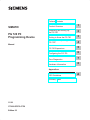
SIMATIC
PG 720 PII
Programming Device
Product Overview
1
Unpacking and Setting Up
the PG 720
2
Getting to Know the PG 720
3
Installing and Operating the
PG 720
4
PG 720 Expansions
5
Configuring the PG 720
6
Error Diagnostics
7
Hardware Information
8
Manual
Appendices
ESD Guidelines
Glossary, Index
11/99
C79000-G7076-C756
Edition 02
A
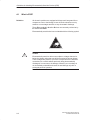
Safety Guidelines
!
!
!
"#- '(/& )(.#(- ().#- 1"#" 3)/ -")/& )-,0 .) (-/, 3)/, )1( *,-)(& - .3 - 1&& - .)
*,).. ." *,)/. ( )((. +/#*'(. "- ().#- , "#!"&#!". #( ." '(/& 3 1,(#(!
.,#(!& ( , ',% - )&&)1- ),#(! .) ." &0& ) (!,
Danger
#(#.-.". ." -0, *,-)(& #($/,3 ), -/-.(.#& *,)*,.3 '! ,-/&. # *,)*, *,/.#)(- ,
(). .%(
Warning
#(#.- .". ." -0, *,-)(& #($/,3 ), -/-.(.#& *,)*,.3 '! ,-/&. # *,)*, *,/.#)(, (). .%(
Caution
#(#.- .". '#(), *,-)(& #($/,3 ), *,)*,.3 '! ( ,-/&. # *,)*, *,/.#)(- , (). .%(
Note
,1-3)/, ..(.#)( .) *,.#/&,&3 #'*),.(. #( ),'.#)( )( ." *,)/. "(&#(! ." *,)/. ), .) *,.#/&,
*,. ) ." )/'(..#)(
Qualified Personnel
(&3 -")/& &&)1 .) #(-.&& ( 1),% )( ."#- +/#*'(. /&# # *,-)(- #( ."
-(- ) ." - .3 !/#&#(- ) ."#- (/& , #( - *,-)(- 1") , /."),#4 .) )''#--#)( .)
!,)/( ( .) .! +/#*'(. -3-.'- ( #,/#.- #( ),( 1#." -.&#-" - .3 *,.#- (
-.(,-
Correct Usage
). ." )&&)1#(!
!
Warning
"#- 0# ( #.- )'*)((.- '3 )(&3 /- ), ." **&#.#)(- -,# #( ." .&)! ), ." ."(#&
-,#*.#)( ( )(&3 #( )((.#)( 1#." 0#- ), )'*)((.- ,)' ).", '(/ ./,,- 1"#" "0 (
**,)0 ), ,)''( 3 #'(-
"#- *,)/. ( )(&3 /(.#)( ),,.&3 ( - &3 # #. #- .,(-*),. -.), -. /* ( #(-.&& ),,.&3 (
)*,. ( '#(.#( - ,)''(
Trademarks
R R ( R , ,!#-., .,',%- ) #'(- "#, *,.#- /-#(! ), ."#, )1( */,*)-- (3 ).", ('- #( ."#- )/'(. 1"#" , , .) .,',%- '#!".
#( ,#(! /*)( ." ,#!".- ) ." .,',% )1(,-
Copyright E Siemens AG 1999 All rights reserved
Disclaimer of Liability
" ,*,)/.#)( .,(-'#--#)( ), /- ) ."#- )/'(. ), #.- )(.(.- #(). *,'#.. 1#.")/. 2*,-- 1,#..( /."),#.3 (,- 1#&& &#& ),
'!- && ,#!".- #(&/#(! ,#!".- ,. 3 *.(. !,(. ),,!#-.,.#)(
) /.#&#.3 ')& ), -#!( , ,-,0
"0 "% ." )(.(.- ) ."#- '(/& ), !,'(. 1#." ."
",1, ( -) .1, -,# #( 0#.#)(- ((). *,&/
(.#,&3 1 ((). !/,(. /&& !,'(. )10, ." . #( ."#'(/&, ,0#1 ,!/&,&3 ( (3 (--,3 ),,.#)(- #(&/ #(
-/-+/(. #.#)(- /!!-.#)(- ), #'*,)0'(. , 1&)'
#'(- ,#" /.)'.#-#,/(!-6 /( (.,#-."(#%
-" .-!#. (/-.,#6/.)'.#-#,/(!--3-.'
)-. " 56 /,(,!
Siemens Aktiengesellschaft
E Siemens AG 1999
"(#& . -/$. .) "(!
C79000-G7076-C756
Preface
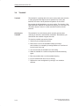
Purpose of the
Manual
This manual contains all the information you need for working with the
PG 720PII programming device. You can use this information to do the
following:
Unpack the programming device and power it up.
Familiarize yourself with the functions and settings of the various
components (display, keyboard, programming facilities, etc.).
Connect the programming device to other units of equipment
(programmable logic controllers, other programming devices).
Expand your system, provided you comply with the necessary
conditions.
Analyze and eliminate simple problems.
Audience
The following persons require the manual:
Users commissioning the programming device themselves or
working with it (editing, debugging).
System administrators operating the programming device in a
network.
Service and maintenance personnel using the PG 720PII for system
expansion purposes or error/fault analysis.
Where is this
Manual Valid?
This manual describes the version of the PG 720PII as available in
April 1999. The Product Information Bulletin supplied with the
PG 720PII contains the latest technical specifications for your
programming device.
Licenses
The approvals, certificates, and licenses for your device are supplied
along with the Product Information Bulletin.
Product name
PG 720PII
Within this publication the product name PG 720PII is given
abbreviated to PG 720 or PG.
Where to Find
Information
Along with your PG 720, you also receive the following documents
which you require for commissioning the device:
The Product Information Bulletin with the valid technical
specifications and the PG 720 installed Software.
For more detailed information about handling the software, please refer
to the appropriate manuals (for example, the STEP 5 manual).
PG 720 PII Programming Device
C79000-G7076-C756-02
iii
Preface
Structure of the
Manual
Chapters 1 to 4 of the manual contain the most important instructions
for commissioning and using the PG 720. Chapters 5 to 8 are
reference sections required in special situations.
Setting up and getting to know your device
Before you start to use your programming device, you should read
about setting up the device in Chapter 2 and about the components
and functions of the PG 720 in Chapter 3.
Installation
Chapter 4 describes the basic steps necessary for commissioning the
PG 720. This chapter also contains instructions for working with
submodules and memory cards for programmable logic controllers and
additional interfaces.
Expansion
Chapter 5 describes how to expand your PG 720 (for example,
installation of memory expansions). Please observe the safety
instructions in this section.
Configuration
Modifications made to the system hardware may make it necessary for
you to adapt the original hardware configuration. This is described in
Chapter 6.
Error/fault diagnostics
Chapter 7 explains how to deal with simple faults and problems that
you can diagnose and, in some cases, eliminate yourself.
Reference data
Chapter 8 contains information about hardware addresses, interrupt
assignments, and connecting cables.
ESD guidelines
The guidelines on the handling of electrostatically sensitive devices are
particularly important for service and maintenance technicians who are
installing expansion units or carrying out error analysis with the
PG 720.
Glossary
The glossary defines and explains important terms.
Alphabetical index
The alphabetical index will help you to find passages in the text relating
to important terms and keywords quickly and reliably.
Additional
Assistance
If you have any questions concerning subjects not covered in the
manual, simply get in touch with the Siemens representative in your
area or call the SIMATIC Hotline. The addresses are listed in your
Product Information Bulletin.
If you have any questions about the manual itself or would like to make
or suggestions, please complete the reply card at the end of the
manual. We would also appreciate it if you would include your own
opinion and appraisal of the manual on the reply card.
iv
PG 720 PII Programming Device
C79000-G7076-C756-02
Contents
Preface . . . . . . . . . . . . . . . . . . . . . . . . . . . . . . . . . . . . . . . . . . . . . . . . . . . . . . . . . . . . . . . .
iii
1
Product Overview . . . . . . . . . . . . . . . . . . . . . . . . . . . . . . . . . . . . . . . . . . . . . . . . . . . . . .
1-1
2
Unpacking and Setting Up the PG 720 . . . . . . . . . . . . . . . . . . . . . . . . . . . . . . . . . . .
2-1
2.1
Setting Up the PG 720 . . . . . . . . . . . . . . . . . . . . . . . . . . . . . . . . . . . . . . . . . . .
2-2
2.2
Moving the Programming Device . . . . . . . . . . . . . . . . . . . . . . . . . . . . . . . . . .
2-6
Getting to Know the PG 720 . . . . . . . . . . . . . . . . . . . . . . . . . . . . . . . . . . . . . . . . . . . . .
3-1
3.1
Hardware Components of the PG 720 . . . . . . . . . . . . . . . . . . . . . . . . . . . . . .
3-2
3.2
Display . . . . . . . . . . . . . . . . . . . . . . . . . . . . . . . . . . . . . . . . . . . . . . . . . . . . . . . .
3-8
3.3
Keyboard . . . . . . . . . . . . . . . . . . . . . . . . . . . . . . . . . . . . . . . . . . . . . . . . . . . . . .
3-9
3.4
Trackball . . . . . . . . . . . . . . . . . . . . . . . . . . . . . . . . . . . . . . . . . . . . . . . . . . . . . . .
3-14
3.5
Drives . . . . . . . . . . . . . . . . . . . . . . . . . . . . . . . . . . . . . . . . . . . . . . . . . . . . . . . . .
3-16
3.6
CD-ROM Drive . . . . . . . . . . . . . . . . . . . . . . . . . . . . . . . . . . . . . . . . . . . . . . . . . .
3-18
3.7
External Power Unit and Battery . . . . . . . . . . . . . . . . . . . . . . . . . . . . . . . . . . .
3-19
3.8
Sound . . . . . . . . . . . . . . . . . . . . . . . . . . . . . . . . . . . . . . . . . . . . . . . . . . . . . . . . .
3-20
Installing and Operating the PG 720 . . . . . . . . . . . . . . . . . . . . . . . . . . . . . . . . . . . . .
4-1
4.1
Connecting the PG 720 to the Power Supply . . . . . . . . . . . . . . . . . . . . . . . .
4-2
4.2
Battery Mode . . . . . . . . . . . . . . . . . . . . . . . . . . . . . . . . . . . . . . . . . . . . . . . . . . .
4-3
4.3
Connecting I/O Devices . . . . . . . . . . . . . . . . . . . . . . . . . . . . . . . . . . . . . . . . . .
4-7
4.4
Working with SIMATIC S5 Memory Submodules . . . . . . . . . . . . . . . . . . . . .
4-12
4.5
Working with SIMATIC Memory Cards . . . . . . . . . . . . . . . . . . . . . . . . . . . . .
4-14
4.6
Working with PC Cards . . . . . . . . . . . . . . . . . . . . . . . . . . . . . . . . . . . . . . . . . .
4-15
4.7
Connecting the PG 720 to other SIMATIC S5 Units . . . . . . . . . . . . . . . . . .
4-17
4.8
Connecting the PG 720 to a SIMATIC S7 Network (MPI/DP) . . . . . . . . . .
4-21
4.9
Networking the PG 720 with Other Stations on PROFIBUS . . . . . . . . . . .
4-23
4.10
Networking the PG 720 and Other Computers on Industrial Ethernet . . .
4-24
4.11
Connection under Windows . . . . . . . . . . . . . . . . . . . . . . . . . . . . . . . . . . . . . . .
4-24
3
4
PG 720 PII Programming Device
C79000-G7076-C756-02
v
Contents
5
6
7
8
A
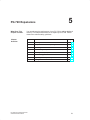
PG 720 Expansions . . . . . . . . . . . . . . . . . . . . . . . . . . . . . . . . . . . . . . . . . . . . . . . . . . . . .
5-1
5.1
Opening the Unit . . . . . . . . . . . . . . . . . . . . . . . . . . . . . . . . . . . . . . . . . . . . . . . .
5-2
5.2
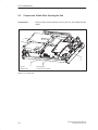
Components Visible After Opening the Unit . . . . . . . . . . . . . . . . . . . . . . . . .
5-4
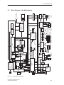
5.3
Block Diagram of the Motherboard . . . . . . . . . . . . . . . . . . . . . . . . . . . . . . . . .
5-5
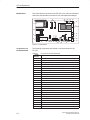
5.4
Switch Settings / Jumpers . . . . . . . . . . . . . . . . . . . . . . . . . . . . . . . . . . . . . . . .
5-7
5.5
Installing Memory Expansion Submodules . . . . . . . . . . . . . . . . . . . . . . . . . .
5-8
5.6
Processor Upgrade . . . . . . . . . . . . . . . . . . . . . . . . . . . . . . . . . . . . . . . . . . . . . .
5-9
5.7
Replacing the Backup Battery . . . . . . . . . . . . . . . . . . . . . . . . . . . . . . . . . . . . .
5-10
5.8
Closing the Unit . . . . . . . . . . . . . . . . . . . . . . . . . . . . . . . . . . . . . . . . . . . . . . . . .
5-11
Configuring the PG 720 . . . . . . . . . . . . . . . . . . . . . . . . . . . . . . . . . . . . . . . . . . . . . . . . .
6-1
6.1
6.1.1
6.1.2
6.1.3
6.1.4
6.1.5
6.1.6
6.1.7
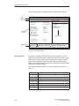
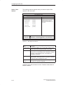
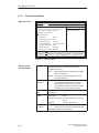
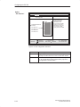
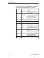
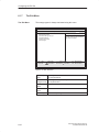
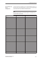
Changing the Device Configuration with SETUP . . . . . . . . . . . . . . . . . . . . .
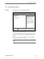
The Main Menu . . . . . . . . . . . . . . . . . . . . . . . . . . . . . . . . . . . . . . . . . . . . . . . . .
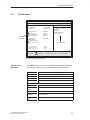
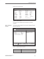
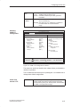
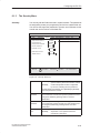
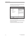
The Advanced Menu . . . . . . . . . . . . . . . . . . . . . . . . . . . . . . . . . . . . . . . . . . . . .
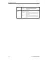
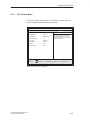
The Security Menu . . . . . . . . . . . . . . . . . . . . . . . . . . . . . . . . . . . . . . . . . . . . . .
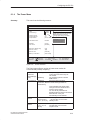
The Power Menu . . . . . . . . . . . . . . . . . . . . . . . . . . . . . . . . . . . . . . . . . . . . . . . .
The Boot Sequence Menu . . . . . . . . . . . . . . . . . . . . . . . . . . . . . . . . . . . . . . . .
The Version Menu . . . . . . . . . . . . . . . . . . . . . . . . . . . . . . . . . . . . . . . . . . . . . . .
The Exit Menu . . . . . . . . . . . . . . . . . . . . . . . . . . . . . . . . . . . . . . . . . . . . . . . . . .
6-2
6-5
6-14
6-19
6-21
6-23
6-25
6-26
6.2
Configuring the PC Card Interface . . . . . . . . . . . . . . . . . . . . . . . . . . . . . . . . .
6-30
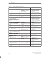
Error Diagnostics . . . . . . . . . . . . . . . . . . . . . . . . . . . . . . . . . . . . . . . . . . . . . . . . . . . . . . .
7-1
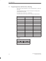
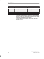
7.1
Programming Device Self-Test Prior to Booting . . . . . . . . . . . . . . . . . . . . .
7-4
Hardware Information . . . . . . . . . . . . . . . . . . . . . . . . . . . . . . . . . . . . . . . . . . . . . . . . . . .
8-1
8.1
Hardware Address Table . . . . . . . . . . . . . . . . . . . . . . . . . . . . . . . . . . . . . . . . .
8-2
8.2
Interrupt Assignments . . . . . . . . . . . . . . . . . . . . . . . . . . . . . . . . . . . . . . . . . . . .
8-5
8.3
PG 720 Video Modes . . . . . . . . . . . . . . . . . . . . . . . . . . . . . . . . . . . . . . . . . . . .
8-6
8.4
Connector Pinouts . . . . . . . . . . . . . . . . . . . . . . . . . . . . . . . . . . . . . . . . . . . . . . .
8-7
8.5
Connecting Cables . . . . . . . . . . . . . . . . . . . . . . . . . . . . . . . . . . . . . . . . . . . . . .
8-14
Guidelines for Handling Electrostatically-Sensitive Devices (ESD) . . . . . . . . .
A-1
A.1
What is ESD? . . . . . . . . . . . . . . . . . . . . . . . . . . . . . . . . . . . . . . . . . . . . . . . . . . .
A-2
A.2
Electrostatic Charging of Persons . . . . . . . . . . . . . . . . . . . . . . . . . . . . . . . . .
A-3
A.3
General Protective Measures Against Electrostatic Discharge Damage .
A-4
Glossary . . . . . . . . . . . . . . . . . . . . . . . . . . . . . . . . . . . . . . . . . . . . . . . . . . . . . . . . . . Glossary-1
Index . . . . . . . . . . . . . . . . . . . . . . . . . . . . . . . . . . . . . . . . . . . . . . . . . . . . . . . . . . . . .
vi
Index-1
PG 720 PII Programming Device
C79000-G7076-C756-02
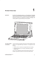
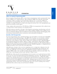
Product Overview
Application
1
The PG 720 programming device is a self-contained unit designed
specifically for an automation environment. Its performance, ergonomic
design, and equipment make it a unit particularly suitable for maintenance
and service as well as for programming, configuring, debugging, and
installing SIMATIC programmable logic control systems.
SIEMENS
The PG’s Hardware
and Software
You can use the PG 720 programming device to program SIMATIC S5 and
SIMATIC S7 programmable logic controllers. It is equipped with the
following:
Interface ports for connection to programmable logic controllers.
Programming facilities for S5 memory submodules and S5/S7
memory cards.
The PG 720 is supplied with system and automation software. The
software components are listed in the Product Information leaflet.
PG 720 PII Programming Device
C79000-G7076-C756-02
1-1
Product Overview
Advantages of the
PG 720
Compared with a PC with standard hardware and software, the
PG 720 programming device of the SIMATIC family has numerous
advantages:
You can develop, debug, and document user programs for
SIMATIC S5 and SIMATIC S7 programmable logic controllers with
the PG 720 without the need for additional hardware or software.
The rugged design and practical functions of the PG 720 make it
particularly suitable for use on-site under tough industrial conditions.
It is extremely light and easy to transport. The PG 720 meets the
specific requirements of industrial environments such as noise
immunity, compliance with the relevant standards, ruggedness,
simple transportation, and commissioning.
The PG 720 is equipped with a battery allowing it to be operated
without a mains connection.
The PG 720 can be set up and operated in a large number of
different ways and positions, and can therefore be used practically
anywhere it is needed.
The PG 720 has all the integral ports necessary for connecting it to
SIMATIC automation devices:
– Programming interface for SIMATIC S5 memory submodules.
– Programming interface for SIMATIC S5 and SIMATIC S7
memory cards in credit card format.
– Communication interfaces for connection to S5 and S7
programmable logic controllers.
The PG 720 is supplied with all the necessary system and
automation software already installed on the hard disk.
Since Windows 98 is also already installed, you can, of course, also
use the PG 720 as a stand-alone workstation, and run all the
standard software available on the market that requires MS-DOS or
Windows.
In terms of performance and expansion capability, your
programming device meets all the normal requirements of a PC.
This means that the PG 720 can also be used as a fully-fledged
personal computer.
1-2
PG 720 PII Programming Device
C79000-G7076-C756-02
Unpacking and Setting Up the PG 720
What Does This
Chapter Contain?
2
This chapter contains important information about unpacking, setting
up, and transporting the PG 720, such as:
Opening and closing the keyboard
Changing the angle of inclination of the device
Using the extra pull-out support
How to move the unit.
Chapter
Overview
Section
Contents
Page
2.1
Setting Up the PG 720
2-2
2.2
Moving the Programming Device
2-6
PG 720 PII Programming Device
C79000-G7076-C756-02
2-1
Unpacking and Setting Up the PG 720
2.1
Setting Up the PG 720
Unpacking Your
PG 720
Unpack your PG 720 as follows:
1. Remove the packing.
2. Do not throw the original packing away. Keep it in case you have to
ship or transport the unit again at some time in the future.
3. Check the packing list to make sure that no components are
missing.
!
Caution
Risk of damage!
Moisture inside the unit can cause serious damage.
When transporting the unit in cold weather, when it may be submitted
to extreme variations in temperature, make sure that the unit is
allowed to reach room temperature slowly before you switch it on.
If condensation has formed, this must be allowed to evaporate before
you switch on. If, for example, the unit is subjected to a temperature
change from –20° C to +20° (–4° F to +68° F) you should wait
approximately 12 hours before switching on the unit.
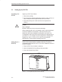
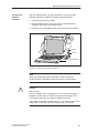
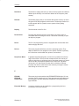
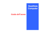
Setting Up on a
Desk Top
The PG 720 is used primarily on a desk or table top. To ensure a
comfortable working position, the PG 720 can be adapted as follows to
suit the work place:
1. Place the PG 720 on the desk or table top.
2. Open the keyboard lock by pulling up the gray handle.
3. Lower the keyboard into position.
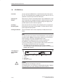
Handle
Figure 2-1 The Programming Device before Opening
2-2
PG 720 PII Programming Device
C79000-G7076-C756-02
Unpacking and Setting Up the PG 720
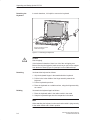
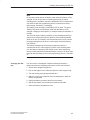
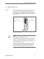
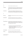
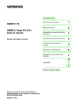
Changing the
Angle of
Inclination
With the keyboard open, you can incline the PG 720 to any angle
between 0° and 90°. To adjust the angle, proceed as follows:
1. Lower the keyboard into position.
2. Pull the support (Figure 2-4) out of the rear of the stand and, if
necessary, pull out the extra support hoop.
3. Incline the unit to an angle that will allow you to work comfortably.
Pivot
Stand
Keyboard opened
Figure 2-2 Changing the Angle of Inclination
Note
When you change the angle of inclination, make sure that the
keyboard cable is not trapped between the device and the stand.
!
Caution
Risk of injury!
There is a danger of the unit tipping over if it is set up at an angle of
inclination of more than 15° without using the pull-out support. This
could lead to personal injury and also damage to the unit.
If the angle of inclination is greater than 15°, you must use the pull-out
support and, if necessary, the extra support hoop in the stand.
PG 720 PII Programming Device
C79000-G7076-C756-02
2-3
Unpacking and Setting Up the PG 720
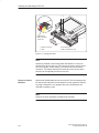
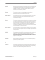
Detaching the
Keyboard
In certain situations, it is helpful to remove the keyboard.
Press in the catches in the
middle of the hinges
Figure 2-3 Detaching the Keyboard
!
Caution
Risk of tipping!
If the keyboard is detached, there is a risk of the unit tipping over.
Before removing the keyboard, make sure that you pull out the support
from the device stand (Figure 2-4) and pull out the additional hoop.
Detaching
You detach the keyboard as follows:
1. Grip the keyboard hinges in the stand behind the keyboard.
2. Pull the locks in the middle of the hinge assembly towards the
keyboard.
3. Pull the keyboard up and out.
4. Place the keyboard on a suitable surface, using the hinge assembly
as a stand.
Refitting
You attach the keyboard again as follows:
1. Place the keyboard cable in the cable conduit in the stand.
2. Snap the keyboard hinges into the receptacles in the stand.
Note
When attaching the keyboard, make sure that the cable is lying correctly
in the cable conduit and is fixed in position.
2-4
PG 720 PII Programming Device
C79000-G7076-C756-02
Unpacking and Setting Up the PG 720
Keyboard Angle
When the keyboard is attached to the unit, its angle of inclination is 6°,
the height of the middle row of keys is 30 mm (about 1 inch). When it is
detached, the angle of inclination is 4.5°, and the height of the middle
row of keys is 27 mm. This is an ideal ergonomic design to allow a
comfortable working position.
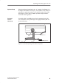
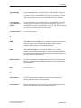
Horizontal
Position
Adjustment
If no table or desk is available, the unit can be operated on the floor.
You can adjust the casing and display through approximately 90o into
the horizontal plane.
CD-ROM drive
Pivot
Stand
Support
Extra support hoop
Figure 2-4 Horizontal Operating Position Without Keyboard
PG 720 PII Programming Device
C79000-G7076-C756-02
2-5
Unpacking and Setting Up the PG 720
2.2
Moving the Programming Device
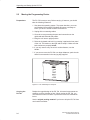
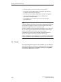
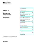
Preparations
The PG 720 is easy to carry. Before carrying it, however, you should
take the following measures:
1. Shut down the operating system. To prevent data loss, you must
exit Windows 98 completely. Windows 98 issues a message to
inform you when it is safe to switch off the device.
2. Unplug all the connecting cables.
3. Close the covers protecting the ports and connections on the
right-hand and left-hand side panels.
4. Bring the unit into an upright position.
5. Raise the keyboard and lock it by pressing it against the front panel
of the unit. The latches on the right and left snap in. Make sure that
both catches are properly locked.
6. If you only want to carry the unit for a short distance, use the
handle.
7. If you want to move the PG 720 over larger distances, pack the unit
and all its accessories in the carrying bag supplied.
Figure 2-5 PG 720 Ready for Transport
Carrying the
PG 720
Despite the rugged design of the PG 720, its internal components are
sensitive to severe vibration or jolts. When moving the PG 720, you
must therefore make sure that it is protected from severe mechanical
forces.
Use the original packing material if you have to ship the PG 720 from
one location to another.
2-6
PG 720 PII Programming Device
C79000-G7076-C756-02
3
Getting to Know the PG 720
What Does This
Chapter Contain?
This chapter contains all the information you require about the most
important components of the device, such as:
LED displays
Drives
Keyboard
Programming facilities of the PG 720
External power unit and battery.
Chapter
Overview
Section
Contents
Page
3.1
Hardware Components of the PG 720
3-2
3.2
Display
3-8
3.3
Keyboard
3-9
3.4
Trackball
3-14
3.5
Drives
3-16
3.6
CD-ROM Drive
3-18
3.7
External Power Unit and Battery
3-19
3.8
Sound
3-20
PG 720 PII Programming Device
C79000-G7076-C756-02
3-1
Getting to Know the PG 720
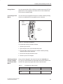
3.1
Hardware Components of the PG 720
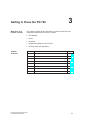
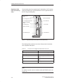
Front
You can access all of the important operator controls and displays from
the front, base, or sides of the unit. Figure 3-1 shows the front of the
PG 720.
Detail 13
9
3
2
9
1
4
7
10
14
14
5
6
12
8
11
1
On/Off switch
6
Keyboard
2
Carrying handle
7
3
LC display
Cover flap for COM1/COM2 port,
MPI/DP port, mouse port, and LPT1/printer
port 1)
4
Cover flap for module ports, memory card
ports, PCMCIA ports, and floppy disk drive 1)
8
Trackball
5
Stand
9
Catches for locking keyboard
10 Pivot
1)
The cover flaps are used to protect the ports from dust,
and can be removed and replaced as required.
2)
Can be accessed from the base when the device is turned
upside down.
3) Press this button for 1 second in order to switch on the
programming device. A hard reset (override) is performed if
you hold down the button longer than 7 seconds.
4) External storage media: hard disk drive, floppy disk drive,
CD-ROM drive.
See Table 3-1 for more information on
the Akku and Power LEDs.
11 Protector strip
12 CD-ROM drive 2)
14 Speaker
Detail 13
LEDs
Akku
Power
Accessing external storage
medium
Submodule programming
active
MPI/DP port active
Figure 3-1 The Front of the PG 720
3-2
PG 720 PII Programming Device
C79000-G7076-C756-02
Getting to Know the PG 720
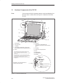
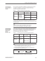
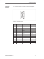
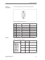
Table 3-1
The LEDs and
What They Mean
The LEDs and What They Mean
Label
LED
Akku
Power
grn
Device is in mains supply mode; external power
unit is supplying power
or
Device is in mains supply mode; battery is recharging
rd
Device is in battery mode; battery charge level
low
blk
Device is in battery mode; battery has shut down
or no battery installed
grn
Device is on, battery mode is selected and battery is not down
grn
flashing
MPI/DP
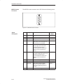
Table 3-2
The Mode LEDs
of the PG 720
Power
Meaning
Device status is “save to DRAM”
blk
Device is off or battery has shut down in battery
mode (battery down)
grn
Accessing external storage medium (hard disk,
CD-ROM, floppy disk)
grn
Submodule programming is in progress
grn
MPI port is active
The Mode LEDs
Akku
blk
grn
a.c. mains supply, battery charged or not installed
blk
or
a.c. mains supply, battery is recharging
blk
blk
Device is off or battery is down in battery mode
grn
blk
Device is on, battery mode
grn
grn
Device is on, a.c. mains supply
grn
or
Device is on, a.c. mains supply and battery is recharging
grn
rd
Device is on, battery charge level is low and battery mode
is selected
grn
rd
or
blk
=
=
=
=
green
red
orange
black, dark
Note
Recharging stops when the battery is fully charged or if, for example,
the temperature overshoots the maximum permissible limit for
recharging. You can check the battery charge level in Windows 98.
PG 720 PII Programming Device
C79000-G7076-C756-02
3-3
Getting to Know the PG 720
Note
Press the On/Off button for approximately one second to switch on the
device. The device switches off automatically if it is powered down in
Windows. If it is not in Windows, switch off the device by pressing the
On/Off button.
If you work under Windows 98, always use the Shut Down menu in the
Start pop-up to switch off the programming device. The PG 720
switches off automatically when you exit Windows.
Holding down the On/Off button for longer than seven seconds triggers
the override function. The device resets and automatically reboots
(useful, for example, if the system freezes).
3-4
PG 720 PII Programming Device
C79000-G7076-C756-02
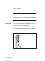
Getting to Know the PG 720
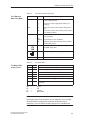
Left-Hand Side
Panel
(Communications
Side)
All the connectors and interface ports for connecting to external
devices are located on the left side panel of the PG 720
(communications side).
VGA port
COM 2 port
Power switch
LEDs
COM 1 port
LPT1 port
Power supply
connector socket
PS/2 mouse
USB port
MPI/DP port
Figure 3-2 Left-Hand Side Panel with Cover Plates Removed
Connectors and
Ports
The following table contains an overview of the various interface ports
and connectors on the left-hand side panel:
Table 3-3
Connectors on the Left-Hand Side Panel of the Unit
Ports and Connectors
Function
VGA port
Connection for external monitor
COM 2
Serial port
RS-232 / mouse
Serial port
Connection for serial mouse
COM 1
RS-232 /MODEM /PLC
Serial port
Connection for S5 programmable
logic controller
MPI (multipoint interface)
Connection for S7 programmable logic
controller
LPT 1 printer
rinter
Parallel port
Connection for parallel
arallel printer
rinter
PS/2 mouse
Connection for PS/2 mouse
External power supply unit
Connection for 17 V DC from external
power supply unit
USB type A serial interface
Port for the Universal Serial Bus
PG 720 PII Programming Device
C79000-G7076-C756-02
Connection for serial printer
3-5
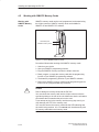
Getting to Know the PG 720
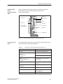
Right-Hand Side
Panel (Processing
Side)
You access the slots for programming S5 submodules, S5/S7 memory
cards, the PCMCIA port, and the disk drive from the right-hand side of
the PG 720 (processing side).
Ejector for PC
cards
PC cards types I/II; slot 2
Ejector for diskettes
PC cards types I/II/III; slot 1
3.5 in. disk drive
Ejector for PCMCIA
cards
Orientation point
Access LED
Memory card port
S5 submodule port
CD-ROM drive
Figure 3-3 Right-Hand Side Panel (with Port Covers Removed)
The following table contains an overview of the ports and connectors
on the right-hand side panel:
Table 3-4
Connectors on the Right-Hand Side Panel of the Unit
Interface Port
Function
PC card type II port ; slot 2
Connection for PC card types I/II
PC card type III port; slot 1
Connection for PC card types I/II/III
S5 submodule port
Programming SIMATIC S5 submodules
Memory card port
Programming SIMATIC memory
cards
Disk drive
Working with 3.5” disks
Note
PC cards is a generic term for Cardbus cards and PCMCIA cards: see
Section 4.6.
3-6
PG 720 PII Programming Device
C79000-G7076-C756-02
Getting to Know the PG 720
Base Panel
You can access the CD-ROM drive and the rechargeable battery from the
base of the PG 720 device.
Battery
CD-ROM-Drive
Ventilation Slits
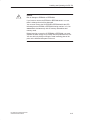
!
There are ventilation slits on the top and bottom panels of the unit.
These slits must not be covered or blocked in any way (for example, by
placing the device on carpets or rugs).
Caution
Risk of overheating!
If you cover the inlet or outlet ventilation slits, you may cause damage
to the PG 720.
Do not place any objects so that they obstruct the ventilating slits in
any way.
PG 720 PII Programming Device
C79000-G7076-C756-02
3-7
Getting to Know the PG 720
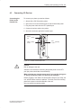
3.2
Display
Available Displays
The PG 720 has a color display.
Contrast control
Figure 3-4 PG 720 Display
Color Display of
the PG 720
The PG 720 has a 12.1” ([ 31 cm) TFT color display with a resolution
of 800 x 600 pixels.
The three primary colors, red, green and blue, can each be displayed in
64 different shades. This means that, including all the secondary
colors, a maximum of 256k different colors can be displayed.
!
3-8
Caution
Risk of injury!
If a display is damaged, liquid crystals may escape. Do not touch this
liquid or allow it to come into contact with your skin in any way, and do
not breath in the vapors. If you do come into contact with the liquid,
wash those parts of the skin affected immediately with alcohol, and
rinse with plenty of water. Then consult a physician immediately.
To clean the display, use only soft cotton cloth with a little glass
cleansing agent, or a special cloth for cleaning glasses. Do not use
water or aggressive solvents (such as alcohol or acetone). Never
touch the display with hard, sharp objects. Avoid exerting any pressure
on the display surface.
PG 720 PII Programming Device
C79000-G7076-C756-02
Getting to Know the PG 720
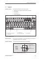
3.3
Keyboard
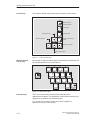
Keyboard Layout
The keyboard is divided into the following areas:
S Alphanumeric or typewriter keyboard with special keys
S LED displays
S Function keys
S Cursor control keys.
3
F1
Esc
2
5
F2
F3
F4
F5
F6
F7
F9
F8
F10
F11
F12
kkk
Num
!
1
~
#w
3
@”
2
Q
W
$
4
%
5
E
^&
6
R
T
& /
7{
Y
* (
8 [
U
( )
9
I
__?
–ß
A
S
>
<
Ctrl
ZY
n
D
X
F
C
G
V
H
B
J
N
K
Mm
Alt
>:
,
2
} *
~
] +
| ’
\ #
Page
Page
?
.
End
Insert
AltGr
Home
” Ä
: Ö
;
L
<;
Break
+
=
{
Ü
[
P
@
Caps
Lock
Pause
Scroll
) =
0 }
O
Print
SysRq
Delete
1
4
1
Alphanumeric keyboard
3
Function keys
2
Special keys
4
Cursor control keys
5
LED display
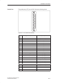
Figure 3-5 Keyboard Layout
Repeat Function
All the keys on the keyboard are of the autorepeat type. The character
is repeated as long as the key is pressed.
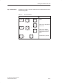
Keyboard Labeling
The keyboard has international and German labeling.
International
National
Example: German
Font size and thickness
reduced
Shift
?
Unshift
ß\
Together
with the ALTGR key
Figure 3-6 The Keyboard Labeling System
PG 720 PII Programming Device
C79000-G7076-C756-02
3-9
Getting to Know the PG 720
Alphanumeric
Keyboard
The largest block of keys on the keyboard is the alphanumeric keyboard
with all the keys for the letters of the alphabet, numerals and special
characters. The characters are arranged in basically the same way as on
a normal typewriter. However, there are a number of special keys which
have special functions for the PG 720.
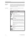
Special Keys
The special keys in the alphanumeric keyboard have the following
functions:
Table 3-5
Functions of the Special Keys
Backspace Key
This key moves the cursor one space to the left and deletes the
character at this position.
Enter Key
(Return, Enter, Line Feed (“New Line”)
Enter
Caps
Lock
The return or enter key is used mainly to terminate a command
line in the operating system; that is, the command you have
typed in is executed when you press this key. For other uses of
this key, please refer to the user manual of the relevant user
program.
CAPS LOCK Key
If you press this key, the middle LED at the top right-hand
corner of your keyboard lights up. All upper case characters
and other characters are output normally. If you want to type
lower case letters in this position, you must first press the shift
key.
If you are using an international keyboard, you cancel this
function by pressing the CAPS LOCK key again. The LED then
goes out.
If you have a German keyboard, you must press the shift $ key
to cancel this function.
NUM Key
F9
With these keys Fn+ ^ NUM , the emulated numeric block is
switched from the alphanumeric keyboard to numeric keys. The
LED display lights up. Press this key again to return to cursor
control.
Tabulator Key
This moves the cursor depending on the selected tabulator
positions.
3-10
PG 720 PII Programming Device
C79000-G7076-C756-02
Getting to Know the PG 720
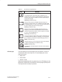
Table 3-5
Functions of the Special Keys
“Fn” Special Key (combination key)
n
In conjunction with a second key (key combination), you
activate other key codes for special applications with this key.
This key is also used to emulate the numeric keypad (Figure
3-8 Numeric Keypad).
CTRL Key (combination key)
Ctrl
This key is only used in combination with other keys. For
example, you press CTRL + ALT + Delete to reset and restart
the operating system. For other uses of this key, please refer to
the user manual of the relevant user program.
ALT Key (combination key)
Alt
This key is only used in combination with other keys. For
example, you can enter the hexadecimal value of an ASCII
character using this key and the numeric keypad for example,
Fn + ALT + 123 corresponds to “{”.
ALTGr Key (combination key)
AltGr
Print
SysRq
Pause
Break
LED Displays
You can use this key together with the other combination keys
to generate other key codes. For example, you can generate
the “\” character on the German keyboard by typing ALTGr + ß.
PRINT (combination key)
Using the Print key, you can output the current screen display
to a printer (depending on the software used).
PAUSE (combination key)
The Pause key interrupts program execution in the majority of
applications.
The LED displays for the keys NUM LOCK and SCROLL LOCK are
located below the function keys F9 to F12 and display the current
status of the keys.
NUM LOCK
CAPS LOCK
SCROLL LOCK
When the programming device is powered up, the LED displays for the
NUM LOCK, CAPS LOCK, and SCROLL LOCK keys light up briefly twice.
The keyboard is then ready for operation.
PG 720 PII Programming Device
C79000-G7076-C756-02
3-11
Getting to Know the PG 720
Cursor Keys
The key block shown in the picture below is used for cursor control.
Move cursor up
Home
Move cursor to
beginning of file
Page
Page back
Page
Page forward
Move cursor left
Move cursor to end
of file
End
Move cursor right
Move cursor down
Figure 3-7 Cursor Control Keys
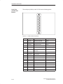
Numeric Keypad
with Fn Key
By pressing Fn and one of these keys, the numbers and characters can
be used provided Num Lock is switched on.
& /
7{
* (
8[
U
n
( )
9
I
) =
0 }
O
P
+
J
K
Mm
: Ö
;
L
>:
.
?
Figure 3-8 Numeric Keypad
Function Keys
There is a row with twelve function keys located above the
alphanumeric keyboard. The assignment of the individual function keys
depends on the software you are working with.
Fn + F9 can also be used to switch the numeric keypad from
alphanumeric keys to numeric keys.
3-12
PG 720 PII Programming Device
C79000-G7076-C756-02
Getting to Know the PG 720
Key Combinations
A selection of some of the most important key combinations are shown
in the following table.
Table 3-6
Key Combinations
Key Combination
Ctrl
+
Alt
+
Effect
Delete
F1
Ctrl
+
Alt
PG 720 PII Programming Device
C79000-G7076-C756-02
~
+
Switch over to international
character set
+
F2
Fn
Restart
Switch over to German
character set: the German
keyboard driver must be
loaded.
Trackball active / passive
3-13
Getting to Know the PG 720
3.4
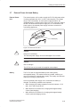
Trackball
Trackball
The trackball is a pointing device for cursor control and menu selection
in many programs that support mouse operation. By moving the
trackball, the cursor can be positioned anywhere on the screen.
By pressing the left-hand button, you set a marker. The function of the
right-hand button depends on the particular program you are using. You
can select objects or items in a menu and start functions with the
trackball.
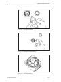
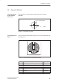
Cleaning the
Trackball
The trackball is in a roller housing which normally prevents dust
collecting on the ball or transmission mechanism. Nevertheless, you
should clean the trackball at regular intervals.
To clean the trackball, proceed as follows:
1. Switch off your programming device.
2. Remove the cover of the trackball housing by turning it
anti-clockwise, for example by inserting tweezers or a similar tool
into the holes in the ring.
3. You can now take the trackball out of its housing.
4. Wash the trackball in a solution of tap water and mild cleansing
agent.
5. Blow any residual dust out of the trackball housing.
6. Dry the trackball and return it to its housing.
7. Replace the cover and tighten it by turning it in a clockwise
direction.
3-14
PG 720 PII Programming Device
C79000-G7076-C756-02
Getting to Know the PG 720
Figure 3-9
Cleaning the Trackball
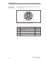
Figure 3-10
Cleaning the Trackball Housing
Figure 3-11
Cleaning the Rollers
PG 720 PII Programming Device
C79000-G7076-C756-02
3-15
Getting to Know the PG 720
3.5
Drives
Drive Types
The PG 720 is equipped with the following drives as standard:
Table 3-7
Standard Drives
Format
Type of Drive
Capacity
Floppy (diskette) drive
3.5 inch
1.44 Mbytes
Hard disk drive
2.5 inch
See Product Information
leaflet
Floppy Disk Drive
Using the floppy disk drive, you can save programs and data on
diskettes and load them on the PG 720.
Types of Diskette
You can use the following diskettes:
Table 3-8
Types of Diskette
Double-Sided High-Density
Diskette
Handling Diskettes
Double-Sided Double-Density
Diskette
3.5 inch
3.5 inch
1.44 Mbytes (135 TPI)
720 Kbytes
80 tracks per side
80 tracks per side
You insert diskettes into the drive as shown below:
Ejector
Access LED
When a floppy disk in the FDD is accessed, this status is indicated by
the access LED on the drive and the access LED for external storage
media on the front of the device.
!
Caution
Risk of data loss!
You must not remove the diskette as long as the access LED is lit.
Otherwise, you may lose the data on the diskette.
Do not remove the diskette until the access LED on the drive or on the
front panel of the PG 720 has gone out.
3-16
PG 720 PII Programming Device
C79000-G7076-C756-02
Getting to Know the PG 720
Hard Disk Drive
You can use a number of different hard disk drives in your PG 720. The
memory capacity of the particular type of hard disk can be found in the
Product Information Bulletin and SETUP program.
When the hard disk is accessed, this status is indicated by the access LED
for external storage media on the front of the device.
!
Caution
Risk of data loss and damage to drive!
Drives are sensitive to vibrations and shock. Any vibrations occurring
during operation can lead to the loss of data or damage to the drive.
After switching off, wait a moment until the drive has stopped spinning
(approximately 10 sec.) before you move the programming device.
PG 720 PII Programming Device
C79000-G7076-C756-02
3-17
Getting to Know the PG 720
3.6
CD-ROM Drive
Overview
You can use the CD-ROM drive to read information from CDs into the
PG 720. The CD-ROM drive is installed at the back of the PG 720. It is
operated on the same port as the hard disk drive.
Opening the
Drawer
Swing the PG 720 into a horizontal position. The CD-ROM drive is now
on the underside of the programming device. Switch the device on. By
briefly pressing the eject button, the drawer springs out slightly. Now
pull the drawer out until it clicks into position.
Inserting /
Removing CDs
Now insert the CD in the drawer with the labeling face up, and press it
firmly down into the center of the turntable. To remove the CD, hold it
by the edges and pull upwards.
Closing the Drawer
Push in the drawer until it closes completely. Do not press the eject
button.
Note
To ensure that the open drawer of the CD-ROM drive is not exposed to
excessive strain, always use one hand to hold the front of the drawer
while inserting or removing a CD-ROM with the other.
Some applications support an EJECT function for opening the
CD-ROM drive: this function does not work with this drive.
The CD is tested when you close the drive and the access LED on the
drive flashes to indicate that the test is in progress:
– if the LED does not stop flashing the CD is bad but readable,
– if the LED flashes several times and then remains on, the CD is not
readable and defective.
Front Panel of
the CD-ROM
Drive
1
2
3
4.
!
3-18
Access LED
Drawer
Eject button
Emergency release
2
1
3
4
Caution
Risk of data loss and damage to the drive.
CD-ROM drives are very sensitive to impermissible vibration. Vibration
during operation can result in damage to the drive or the CD.
PG 720 PII Programming Device
C79000-G7076-C756-02
Getting to Know the PG 720
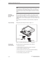
3.7
External Power Unit and Battery
External Power
Unit
The external power unit is used to supply the PG 720 with power when
it is being operated with 120 V or 230 V mains supplies. The voltage
range is set automatically. In mains power supply operation, the
integrated battery is charged at the same time. The connecting cable to
the PG 720 has an external power supply unit. For connection to the
power system, the external power supply unit has a connector for
non-heating appliances.
LED-Display
Figure 3-12 External Power Unit
!
Caution
Danger of overheating!
The external power supply unit can be damaged if it is covered.
!
Caution
Risk of damage!
The PG 720 can only be used with supplied mains adapter.
Battery
The PG 720 has an integrated NiMH (nickel metal hydride)
rechargeable battery. This makes the device portable, meaning you
can use it without the external power supply. The battery also prevents
data loss occurring on power failure.
Once the external power supply unit is connected, the battery is
charged. The following conditions are important:
When charging, the battery temperature must be between + 5° C
and + 40° C (40° F and 100° F).
When the device is switched off, charging takes approximately
2 hours (fast charging).
When the device is switched on, charging takes approximately
8 hours (reduced charging current).
PG 720 PII Programming Device
C79000-G7076-C756-02
3-19
Getting to Know the PG 720
Charging stops as soon as the battery is fully charged.
In storage, a fully charged battery runs down in approximately
2 months. It must then be recharged.
The battery has an integral charge-status monitor (”fuel gauge”).
You can check the battery charge level in Windows 98.
See Section 4.2 Battery Mode.
It is advisable to run a teach-in cycle every now and again
(see Section 4.2).
Note
The green ”Battery” LED does not necessarily mean that the battery is
fully charged. Charging is cut short for safety reasons if the battery
temperature drops below 5°C or rises above 40°C.
Whenever possible, avoid running down the battery too far. Switch off
the unit when it is not in use and remove the battery connector (see
Section 4.2) if it will not be used for some time (weeks).
The Battery LED goes red and an acoustic warning sounds if the
battery is in danger of discharging fully (see Section 4.2)
Bear in mind that you must unplug the a.c. cord from the mains socket
in order to disconnect the programming device from the mains supply.
3.8
Sound
The programming device has two built-in speakers. You can adjust the
output volume either by clicking the Loudspeaker button in the taskbar
or by opening the Start menu in Windows and selecting Programs >
Accessories > Multimedia > Volume.
3-20
PG 720 PII Programming Device
C79000-G7076-C756-02
Installing and Operating the PG 720
What Does This
Chapter Contain?
4
This chapter describes what you have to do to set up your PG 720
correctly for operation. This includes:
The basic steps for commissioning your PG 720
Working in the battery mode and changing the battery
Working with memory submodules and cards for the programmable
logic controllers
Connecting your PG 720 to other devices.
Chapter
Overview
Section
Contents
Page
4.1
Connecting the PG 720 to the Power Supply
4-2
4.2
Battery Operation
4-3
4.3
Connecting I/O Devices
4-7
4.4
Working with SIMATIC S5 Memory Submodules
4-12
4.5
Working with SIMATIC Memory Cards
4-14
4.6
Working with PC cards
4-15
4.7
Connecting the PG 720 to other SIMATIC S5 Units
4-17
4.8
Connecting the PG 720 to a SIMATIC S7 Network
(MPI/DP)
4-21
4.9
Networking the PG 720 with Other Stations on
PROFIBUS
4-23
4.10
Networking the PG 720 and Other Computers on
Industrial Ethernet
4-24
4.11
Connection under Windows
4-24
PG 720 PII Programming Device
C79000-G7076-C756-02
4-1
Installing and Operating the PG 720
4.1
Connecting the PG 720 to the Power Supply
Connecting to the
Power Supply
You can operate the PG 720 on 120 V and 230 V power systems using
the external power supply unit. The voltage is selected automatically.
1. Plug the power supply cable supplied with the unit into the
connector on the external power supply unit.
2. Connect the power cable to a socket outlet with a grounded
protective conductor.
3. Connect the low voltage connector to the connection for the external
power supply on the unit. The power supply cable to the PG 720 is
integrated in the external power supply unit.
4. The device is now ready for power supply operation and the battery
will be charged if required.
Connection for external
power unit
VN = 17.5 V DC
Figure 4-1 Power Supply Connection
Note
The power plug must be disconnected to isolate the unit completely
from the supply.
For operation in Canada and the US, a CSA or UL listed power supply
cable must be used.
The external power supply unit is intended for operation with grounded
power supply systems (TN networks according to IEC 364-3).
The unit is not intended for operation with non-grounded or
impedance-grounded systems (IT networks).
The Power Management function can interrupt battery charging if
current consumption is high while the programming device is in
operation.
4-2
PG 720 PII Programming Device
C79000-G7076-C756-02
Installing and Operating the PG 720
4.2
Battery Mode
Charge-Status
Indicator
The battery has electronic circuitry for showing the current charge
status. The electronics incorporate a metering unit which has to be
calibrated at regular intervals so that it can compensate for error. The
chemical properties of the battery change in the course of time, so the
electronics have to relearn the battery’s characteristics at regular
intervals. A teach-in cycle ensures that the battery’s maximum charge
capacity is at your disposal.
Note
There is a danger of the charge-status indicator misinterpreting the
actual capacity of the battery if a lengthy period of time is allowed to
pass between teach-in cycles. This can result in an unexpected
shutdown with no prior warning.
Teach-in Cycle
(calibration cycle)
Run a teach-in cycle:
S once every month,
S if a prolonged period of time has elapsed since the battery was last
used,
S if you think that the battery no longer operates at full capacity,
S if the programming device shuts down unexpectedly with no prior
warning,
S if operating time on battery becomes shorter.
S If during startup the error message “Battery needs calibration
cycle” appears (has to be acknowledged with the F1 key).
Performing a
Teach-in Cycle
Broadly speaking, the procedure for a teach-in cycle is as follows:
S Charge the battery until the charge-status indicator shows 100%.
See the section entitled ”Displaying Charge Status” for instructions
on how to view the indicator.
S Leave the programming device switched on to drain the battery: the
programming device will switch itself off when the battery is
discharged. Remember to disconnect the power unit from the
PG 720 so that the battery can discharge.
S Once the programming device has switched itself off, start another
charge cycle by reconnecting the external power unit to the PG 720.
The teach-in cycle terminates automatically approximately 10
minutes later.
PG 720 PII Programming Device
C79000-G7076-C756-02
4-3
Installing and Operating the PG 720
Note
You can speed up the discharge stage by deactivating the Power
management functions in the BIOS (see Setup menu, Section 6.1.4
Power Savings Disabled....). Under Windows 98 you can achieve the
fastest possible discharge by clicking Taskbar > Start > Settings >
Energy Management > Energy Schematics > Settings for Energy
Schematics > Battery Mode and entering ’Never’ in all categories.
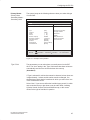
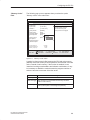
Displaying Charge
Status
The battery charge status is shown in the Summary screen (see
Figure 6-6). You can freeze this screen for viewing by hitting the Pause
key as soon as the Summary screen appears as the programming
device powers up.
Windows 98 has a convenient feature for viewing the battery charge
status. To check the battery charge status: Taskbar > Start > Settings
> Energy Management > Battery Indicator.
Battery Mode
If no external power unit is connected, the PG 720 can operate on the
built-in rechargeable battery.
1. Switch on the programming device. Check that the battery is
adequately charged before you start work.
Note
The battery charge status is displayed in the Summary screen at the
end of the system boot phase; you can also check the charge status
under Windows 98.
2. Work with your PG 720 in the usual way.
3. When the Battery LED turns red in battery mode, the battery has
discharged to a minimal residual-charge level. Save your data and
close your work session.
4-4
PG 720 PII Programming Device
C79000-G7076-C756-02
Installing and Operating the PG 720
Note
Do not start a work session in battery mode unless the battery is fully
charged. This is the only way of ensuring that the full on-battery
operating time is available; note that if the Battery LED is orange when
you switch on with the programming device is connected to the a.c.
mains supply, the battery is recharging.
The battery is not recharging if the Battery LED is green. The green
”Battery” LED does not necessarily mean that the battery is fully
charged. Charging is interrupted if, for example, battery temperature is
too high.
You may find that the battery is partially or fully discharged when you
switch on the programming device (because it has drained gradually
while not in use, for example). Use the external power unit to connect
the programming device to the a.c. mains supply so that the battery
can recharge.
The battery recharges as soon as the programming device is
connected to the a.c. mains supply by means of the external power
unit: the battery recharges in fast-charge mode if the programming
device remains switched off (this takes about 2 hours) or in about eight
hours at reduced charge current if the programming device is switched
on.
Changing the Battery
You can remove a discharged or defective battery and install a
replacement (see the Operating Instructions for the order number):
1. Switch off the programming device.
2. Pull out the support in the stand and open the extra support hoop.
3. Turn the housing through approximately 90°.
4. Slide the cover in the underside of the housing down to open the
battery compartment.
5. Unplug the battery connector and lift out the battery.
6. Slip the new battery into position and reconnect the cable.
7. Close the battery-compartment cover.
PG 720 PII Programming Device
C79000-G7076-C756-02
4-5
Installing and Operating the PG 720
1
2
2
Unlocking the
battery connector
- press here
3
4
1 Battery connector
3 Pull out Support
2 Akku
4 Akku compartment cover
Figure 4-2 Changing the Akku
Note
Whenever possible, avoid running down the batterie to a low level.
Switch off the device after use. If the device will not be used for some
time (for example, several weeks), you should remove the battery
connector. The batterie then has no connection to the device and in
this way can be optimally saved for future use.
Disposal of Used
Batteries
Nickel-metal hydride batteries can be recycled. Their components can
be used as raw materials for new batteries or other products. Effective
recycling of batteries is only possible when the used batteries are
collected according to type.
Note
Observe the local regulations for disposal of materials.
4-6
PG 720 PII Programming Device
C79000-G7076-C756-02
Installing and Operating the PG 720
4.3
Connecting I/O Devices
Connecting the
Printer to the
Parallel Port
To connect your printer, proceed as follows:
1. Switch off the PG 720 and the printer.
2. Open the cover to the interface ports on the left-hand side panel.
3. Plug the printer cable into the LPT1 parallel port.
4. Connect the printer cable to the printer.
5. Screw the connector tight at the interface port.
COM 2
(serial)
port
COM 1
socket (serial)
LPT 1
socket (parallel)
Figure 4-3 Position of the Printer Ports
!
Caution
Risk of damage to the unit!
Switch the unit off before connecting the parallel printer to the LPT 1
port (the printer should also be switched off).
Make sure that you use the correct port. If you use the wrong port
or wrong connecting cables, the port may be damaged.
Before plugging in the cables, the electrostatic charge of your body, the
unit, and the cables must be equalized. To do this, touch the mounting
plate for the ports on the left-hand side of the unit.
Only use original connecting cables.
PG 720 PII Programming Device
C79000-G7076-C756-02
4-7
Installing and Operating the PG 720
Connecting the
Printer to the
Serial Port
You can also connect your printer to the PG 720 using a serial COM port.
You will find information on how to adapt and set your interface and which
connecting cable you require in the description of your printer.
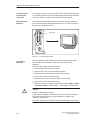
Recommended
Monitors
You connect external multisynchronous monitors using the standard
VGA connector on the left-hand panel side of the unit. We recommend
that you use a Siemens monitor.
VGA socket
Figure 4-4 Connecting the Monitor
Connecting
Monitors
You must switch the PG 720 off before connecting the monitor cable.
You will find further information about the connector pinout in
Chapter 8.
To connect the monitor, proceed as follows:
1. Switch off the PG 720 and the monitor.
2. Open the port cover on the left-hand side panel.
3. Plug the monitor cable into the VGA socket connector.
4. Secure the connector with the screws.
5. Plug the other end of the monitor cable into the monitor.
6. Switch on the PG 720 and the monitor.
7. Make the necessary changes in the SETUP program (Menu > Main
> Hardware Options “CRT enabled”, “LCD enabled” “SIMULTAN”).
!
4-8
Caution
Danger of damaging the monitor!
If you want to set higher clock frequencies and resolutions, first make
sure that the monitor you are using is suitable for a higher clock
frequency and resolution.
If the clock frequency is too high, this can cause damage to the monitor.
PG 720 PII Programming Device
C79000-G7076-C756-02
Installing and Operating the PG 720
Using a Mouse
You can connect both a PS/2–USB and a serial mouse to the PG 720.
When the PG 720 is supplied, the mouse driver for the trackball and
PS/2 mouse is already loaded.
Connecting a PS/2
Mouse
You can connect an external PS/2 mouse or another external pointing
device to an additional PS/2-compatible mouse connector.
COM2
Port for
serial mouse
(connector)
Port for
PS/2 mouse
(socket)
Figure 4-5 Connecting a PS/2 Mouse
To connect the mouse, proceed as follows:
1. Switch off your device.
2. Open the port cover on the left-hand side panel.
3. Plug the cable of the PS/2 mouse or another external pointing
device into the mouse connector.
4. Secure the connector with the screws.
5. Switch on your PG 720 again.
Switching between
Internal Trackball
and External PS/2
Mouse
Once you have plugged in the external mouse and restarted your
PG 720, the internal trackball is deactivated and remains inactive until
the PG 720 is powered up again without the external mouse.
Table 4-1
Trackball/External Mouse Mode
State
Internal Trackball
No mouse
Active
External mouse connected
Deactivated
PG 720 PII Programming Device
C79000-G7076-C756-02
External PS/2 Mouse
Active
4-9
Installing and Operating the PG 720
Connecting a
Serial Mouse
You can connect a serial mouse to the COM2 serial port. To operate a
serial mouse, the appropriate mouse driver must be initialized and
assigned parameters. You will find the information you need to do this
in the description of your mouse or in the description of the operating
system.
1. Switch off your device.
2. Open the cover of the interface ports on the left-hand side panel.
3. Plug the serial mouse into the mouse connector labeled COM2.
4. Secure the connector with the screws.
5. Switch on your PG 720 again.
6. Connect external mouse to USB interface.
Choosing Another
Keyboard
You can connect another PS/2-type keyboard to your PG 720 instead
of the one supplied with it.
Keyboard connection
Figure 4-6 Connecting a PS/2 Keyboard
4-10
PG 720 PII Programming Device
C79000-G7076-C756-02
Installing and Operating the PG 720
Connecting a PS/2
Keyboard
To connect the keyboard, proceed as follows:
1. Switch off your device.
2. Unplug the keyboard connector from the base of the unit.
3. Plug in the PS/2-type keyboard connector.
Note
It is advisable to use a keyboard cable with an angled connector, so
that the connector does not extend beyond the back panel.
The keyboard cable must be inserted in the cable conduit on the back
panel of the unit, otherwise the connector can work loose when the
device is tilted.
Connecting USB
Periphery
You can connect peripheral devices with USB interfaces to the USB
port.
1. Open the port cover on the left-hand side panel.
2. Plug the USB cable into the port, for example under Windows 98.
The device connected in this way is available as soon as it has been
registered by the Plug and Play operating system.
USB port
Figure 4-7 USB Port
PG 720 PII Programming Device
C79000-G7076-C756-02
4-11
Installing and Operating the PG 720
4.4
Working with SIMATIC S5 Memory Submodules
Working with
SIMATIC S5
Submodules
You can read and program SIMATIC S5 EPROMs and EEPROMs
using the 48-pin S5 EPROM and EEPROM programming port. You will
find information about using the programming software in the STEP 5
User Manual.
S5 EPROM/
EEPROM port
Figure 4-8 S5 Submodule (EPROM/EEPROM) Programming Port
Proceed as follows when working with the S5 submodule programming
ports:
1. Switch on your device.
2. Start the EPROM function in your STEP 5 software (version V 6.x).
3. Plug the S5 memory submodule into the 48-pin programming port.
4. Read, program, or erase (EEPROMs only) your S5 memory
submodule with the EPROM programming package of your STEP 5
software.
5. Remove the S5 memory submodule.
6. Terminate the EPROM programming package of your STEP 5
software.
Note
Only program SIMATIC S5 submodules when you are operating the
device using the power supply system (the external power supply unit
must be plugged in). Only then can you be sure that programming will
not be interrupted by a power outage if the battery is low.
4-12
PG 720 PII Programming Device
C79000-G7076-C756-02
Installing and Operating the PG 720
!
Caution
Risk of damage to EPROMs or EEPROMs!
If you insert or remove the EPROM or EEPROM while it is in use,
there is a danger that it will be damaged.
You must not remove the S5 EPROM or EEPROM while the LED
indicating that the EPROM or EEPROM is being read etc. is lit. You
cannot work simultaneously with S5 memory submodules and
memory cards.
Before inserting or removing S5 EPROMs or EEPROMs, you must
equalize the static charge on your body with the potential on the unit.
You can do this by briefly touching the metal mounting plate of the
ports on the left-hand side panel of the unit.
PG 720 PII Programming Device
C79000-G7076-C756-02
4-13
Installing and Operating the PG 720
4.5
Working with SIMATIC Memory Cards
Working with
SIMATIC Memory
Cards
SIMATIC memory cards can be read, programmed, and erased using
the 68-pin connector. SIMATIC memory cards are available for
SIMATIC S5 and SIMATIC S7 software.
Orientation point
SIMATIC memory cards
Figure 4-9 Slot for SIMATIC Memory Cards
Proceed as follows when working with SIMATIC memory cards:
1. Switch on your device.
2. Start your SIMATIC programming function.
3. Plug the SIMATIC memory card into the 68-pin connector.
4. Read, program, or erase the memory card with the programming
function of your SIMATIC programming software.
5. Terminate the programming function of your SIMATIC software.
6. Remove the SIMATIC memory card from the programming port for
further use in a programmable logic controller.
!
4-14
Caution
Risk of damage to memory cards and the PG 720!
You must insert the memory card into the 68-pin connector with the
type label pointing to the rear of the unit. Make sure that the orientation
point beside the slot matches the point on the card.
If you attempt to plug in the memory card the wrong way round, you
may damage your PG 720 or memory card.
You must not remove the memory card while the LED indicating that
the card is being read etc. is lit. You cannot work simultaneously with
S5 memory submodules and memory cards.
PG 720 PII Programming Device
C79000-G7076-C756-02
Installing and Operating the PG 720
4.6
Working with PC Cards
The PC card interface supports Cardbus cards (32-bit) and PCMCIA
cards (16-bit). The PG 720 has two PC card ports. You can plug
communication modules for MODEM, FAX-MODEM, ISDN, Token
Ring, ETHERNET, memory expansion and SCSI interface modules in
credit-card format into these ports. You can plug in two type II cards or
one type III card.
PC Cards
PC card interface, type I/II
(slot 1)
PC card interface, type I/II/III
(slot 2)
Ejector for
PC cards
Figure 4-10 PC Card Interface
!
Caution
Risk of damage to PC cards and the PG 720!
Always insert PC cards with the front face turned toward the rear of
the PG 720. The front face generally bears the company and product
designation and is labeled ”This side up”, or words to that effect.
You might damage the PG 720 and the PC card if you attempt to insert
the PC card the wrong way round.
Always discharge your body’s charge of static electricity by briefly
touching a grounded part of the device (e.g. the metal mount of the
port) before inserting or removing a card (in accordance with the
instructions for handling electrostatically sensitive components)
PG 720 PII Programming Device
C79000-G7076-C756-02
4-15
Installing and Operating the PG 720
Note
Do not use PC cards along with a SIMATIC-S5 module or a SIMATIC
memory card. Always follow the instructions in your Operating
Instructions.
Note
In order to use a PC card you must enter BIOS-SETUP, open the Main
menu, select the Hardware Option submenu and set “Cardbus/
PCMCIA Slot” to “Enabled”.
4-16
PG 720 PII Programming Device
C79000-G7076-C756-02
Installing and Operating the PG 720
4.7
Connecting the PG 720 to other SIMATIC S5 Units
Point-To-Point
Connection
In this section, you will learn how to connect your PG 720 to a
programming device or S5 programmable logic controller using a
point-to-point connection.
You can establish a point-to-point connection by connecting the PG 720
to another programming device or a programmable logic controller
using
An RS-232 connection
A TTY connection
Configuring
Interfaces with
Line Current
(TTY, 20 mA)
To ensure reliable data transfer, several factors must be taken into
account. The maximum data transfer rate (baud rate) depends on the
distance, the type of cable, the pin assignment of the interface and
external interference.
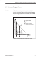
Rules
You can reduce interference by choosing the right transmission cable and
connecting it properly, and by observing the following guidelines:
Use a shielded cable with a low line resistance (130 W / km) (about
40 W kft) and low capacitance (< 90 pF/m) (about 27 pF/ft).
Twisted-pair cables are less susceptible to noise and interference. A
low line resistance results in reduced voltage excursions and shorter
charge reversal times. The line resistance decreases with increasing
conductor cross-section for the same length of cable.
The shorter the transmission link, the higher the maximum possible
data transfer rate.
If there is an active sender and an active receiver at the same end of
the transmission link, the sequence of access priority to the
transmission circuit must be taken into account in order to achieve the
longest possible transmission link.
Signal lines and power lines must not run together. Signal lines must
be installed as far away as possible from sources of strong interference
(for example, 400 V 3-phase power cables).
The active TTY interface with a 12 V no-load voltage has been tested
on a 100 m (1100 ft) long cable at a transmission rate of 9600 bps in
an environment with normal levels of noise (field strength < 3 V/m or
1 V/ft). If a shielded LiYCY 5 x 1 x 0.14 shielded cable is used, reliable
transmission is possible over a distance of up to 100 m (1100 ft). The
AS511 protocol (only one transmitter at a time) was used for testing.
Note
The interference field of the source decreases exponentially with the
distance.
PG 720 PII Programming Device
C79000-G7076-C756-02
4-17
Installing and Operating the PG 720
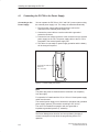
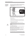
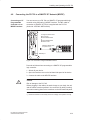
Connecting the
PG 720 to S5
Programmable
Controllers
You can connect the PG 720 to a SIMATIC S5 programmable logic
controller using the COM1/TTY interface port. The cable for connecting
to SIMATIC S5 CPUs is supplied with the PG 720 ( Order
no.: 6ES5734-2BD20).
COM 1
(socket)
Figure 4-11 Connecting the PG 720 to an S5-Programmable Logic Controller
You connect your PG 720 to a SIMATIC S5 programmable logic
controller as follows:
1. Switch off your device.
2. Open the cover of the interface ports on the left-hand side panel.
3. Plug the cable into the COM1/RS-232 modem/PLC interface port.
4. Secure the connector with screws.
5. Plug the cable into the corresponding port on the CPU of the
programmable logic controller.
!
Caution
Risk of damage to the PG 720!
The interface port may be damaged if you confuse the connections or
use the wrong connecting cables.
Make sure that the TTY cable of the PG 720 is plugged into the
COM1/TTY port and not into the LPT1 port.
Before plugging the cable in, the static charge on your body, the unit,
and the connecting cables must be equalized. You can do this by
briefly touching the metal mounting plate for the interfaces on the
left-hand side panel of the device.
Only use original cables to connect the programmable logic controller.
4-18
PG 720 PII Programming Device
C79000-G7076-C756-02
Installing and Operating the PG 720
Connecting the
PG 720 Using an
Adapter
The connecting cable 6ES5 734-2BD20 is supplied with the PG 720.
An adapter is available for connecting the programmable logic
controller using older standard cables.
Table 4-2
Adapter for the PG 720 Connecting Cable
Port
Connection
Connecting Cable
Order No.
Adapter
6ES5 734-2BD20
PG 720 with
ith
SIMATIC S5
COM1 as
rogrammable
TTY interface programmable
logic controller
6ES5 731-1xxx0
15-pin
6ES5 731-6AG00
6ES5 731-0xxx0
25-pin
6ES5 731-6AG00
To allow a data transfer rate of 9600 bps up to a distance of 100 m
(1100 ft), the receiving diode is connected to ground (reference) via the
connecting cable.
Note
Cables of various lengths are available under Order No.
6ES5 734-2xxx0 (xxx stands for the length in meters).
Connecting the
PG 720 to Other
Programming
Devices
(RS-232, TTY)
If you want to connect your PG 720 to another programming device,
you can plug the appropriate connecting cable into the RS-232 or TTY
interface port. You will find more detailed information about the
connecting cables listed below in Chapter 8.
Table 4-3
Connecting the PG 720 to Other Programming Devices
Port
Connection
Connecting cable
Order No:
COM1 as
RS-232 interface
PG 7xx with
PG 7xx
6ES5 733-5BD202
COM1 as
TTY interface
PG 7xx with
PG 6xx
Series connection
of
6ES5 733 -2xxx02
and
6ES5 731-6AG001)
Adapter
6ES5 731-6AG00
Note
1. When connecting the programming devices in series, make sure you
connect the cable the right way round (see Figure 4-12).
2. The connecting cable is available for order only as a spare part. The
connecting cable is described in Section 8.
Adapter
active
PG 7XX
6ES5 731-6AG00
Connecting cable
passive
PG 6XX
6ES5 733-2xxx0
Figure 4-12 Direction of Connection: Adapter-Connecting Cable
PG 720 PII Programming Device
C79000-G7076-C756-02
4-19
Installing and Operating the PG 720
Note
If you connect two programming devices using the TTY interface, you
must deactivate the TTY interface (COM1) on one of the devices by
changing the jumper settings. When supplied, this interface is always
active.
Activating/
Deactivating the
PG 720
When your PG 720 is supplied, the COM1 (TTY) serial port is active
(20 mA current loop). When you connect two programming devices
using the COM1 (TTY) serial port, you must deactivate the port on one
of these devices. The PG 720 has jumpers on the mother board for this
purpose.
These jumpers are accessible if you open the battery compartment
cover.
Jumper Settings
Change the jumper settings as shown in Figure 4-13.
deactivated
1 2 3 4 5
activated
1 2 3 4 5
TTY receive
TTY send, open
TTY send
TTY receive
Figure 4-13 Activating, Deactivating the TTY Port using jumpers
Changing the
Jumper Setting
Proceed as follows to deactivate the port on the PG 720:
1. Switch off your device.
2. Adjust the position of the PG 720 so that it is horizontal.
3. Open the battery compartment cover.
4. Remove jumpers 2-3 and 4-5 at the top left beside the battery.
5. Insert the jumper in slot 1-2 (see Figure 4-13).
6. Close the battery compartment cover.
4-20
PG 720 PII Programming Device
C79000-G7076-C756-02
Installing and Operating the PG 720
4.8
Connecting the PG 720 to a SIMATIC S7 Network (MPI/DP)
Connecting an S7
Programmable
Controller via an
MPI/DP Interface
You can connect your PG 720 to a SIMATIC S7 programmable logic
controller using the floating*) MPI/DP interface. The MPI cable for
connection to SIMATIC S7 CPUs is supplied with the PG 720.
(Order No.: 6ES7901-0BF00-0AA0)
In a high-interference area:
Bus connector
6ES7972-0BB10-0XA0
or
6ES7972-0BB20-0XA0
6ES5762-1AA21
6ES7901-0BF00-0AA0
5 m (about 16 ft.)
MPI/DP port
Figure 4-14 Connection Using the MPI/DP Interface
Proceed as follows when connecting to a SIMATIC S7 programmable
logic controller:
1. Switch off your device.
2. Open the interface cover on the left-hand side panel of the device.
3. Connect the cable to the MPI/DP interface.
!
Caution
Risk of damage to the PG 720!
Before plugging in the cables, the static charge on your body, the unit,
and the cables must be equalized. You can do this by briefly touching
the metal mounting plate for the interfaces on the left-hand side panel.
*) Electrical isolation in the safety extra-low voltage circuit (SELV circuit).
PG 720 PII Programming Device
C79000-G7076-C756-02
4-21
Installing and Operating the PG 720
Connecting
Via the MPI/DP interface, you can connect your programming devices
to
MPI networks (S7-200, S7-300, and S7-400) or
PROFIBUS DP networks (DP components).
MPI/PROFIBUS DP
Network
Up to 32 devices (PC, programming device, or programmable
controller) can be connected to the MPI/DP interface to form a network
segment. The physical connection to the MPI/PROFIBUS DP network
is via a floating RS485 interface which is a component of the
programming device basic module.
Several MPI/PROFIBUS DP network segments can be connected via
repeaters. The complete MPI/PROFIBUS DP network can comprise up
to 127 stations. The data transmission rate in the MPI network is
187.5 Kbps. Data transmission rates from 9.6 Kbps to 12 Mbps are
possible in the PROFIBUS-DP MPI network.
Note
You will find more information on setting up an MPI/DP network in the
manual ”Profibus Networks” Order No.: 6GK 1970-5CA10-0AA0 or in
SIMATIC NET.
4-22
PG 720 PII Programming Device
C79000-G7076-C756-02
Installing and Operating the PG 720
4.9
Networking the PG 720 with Other Stations on PROFIBUS
Networking the
PG 720 on
PROFIBUS
PROFIBUS is an open and robust bus system for industrial use. It can
be used to configure networks with up to 32 stations per segment. The
data transfer rate for PROFIBUS is 1.5 Mbps. PROFIBUS-DP
supports data-transfer rates from 9,6 Kbaud to 12 Mbaud.
How the Network
Functions
The network operates on the master-slave principle with token passing
(complying with DIN19245, PROFIBUS). It distinguishes between
active and passive stations. An active station receives the token and
passes it on to the next station within a specified time.
Hardware
Requirements
Using the following components, for example, you can connect or
network the PG 720 with PROFIBUS:
RS 485 MPI/DP interface adapter, integrated
Shielded, twisted pair (bus cable or connecting cable to network).
Note
You will find more detailed information about the SIMATIC Net PC
cards in the SIMATIC NET Catalog IK 10.
PG 720 PII Programming Device
C79000-G7076-C756-02
4-23
Installing and Operating the PG 720
4.10 Networking the PG 720 and Other Computers on Industrial Ethernet
Networking the
PG 720 on
Industrial Ethernet
Industrial Ethernet is a bus system for industrial use based on
ETHERNET (ISO 8802/3). The main features of Industrial Ethernet are
speed (10 Mbps), simple expansion, open communication, and
widespread application.
How the Network
Functions
Industrial Ethernet is the name of Siemens networks and network
components operating according to the CSMA / CD (ETHERNET)
principle. Industrial Ethernet is a bus-type LAN that uses a triaxial cable
(H1) as its transmission medium.
Hardware
Requirements
To connect or network the PG 720 with Industrial Ethernet, a
PC-card-ETHERNET interface module is required.
Note
You will find more detailed information about the SIMATIC Net PC
cards in the SIMATIC NET Catalog IK 10.
4.11 Connection under Windows
Windows supports point-to-point connections via the LPT or COM port.
The connecting cables are standard, commercially available products.
More information is available in the Networks section of the Windows
description and in the online Help system under “Connection to Another
Computer”.
4-24
PG 720 PII Programming Device
C79000-G7076-C756-02
5
PG 720 Expansions
What Does This
Chapter Contain?
Chapter
Overview
You can enhance the performance of your PG 720 by adding additional
memory. This chapter describes how to expand your PG 720. Please
observe the relevant safety guidelines.
Section
Contents
Page
5.1
Opening the Unit
5-2
5.2
Components Visible After Opening the Unit
5-4
5.3
Block Diagram of the Motherboard
5-5
5.4
Switch Setting / Jumper
5-7
5.5
Installing Memory Expansion Modules
5-8
5.6
Processor Upgrade
5-9
5.7
Replacing the Backup Battery
5-10
5.8
Closing the Unit
5-11
PG 720 PII Programming Device
C79000-G7076-C756-02
5-1
PG 720 Expansions
5.1
Opening the Unit
Prerequisites
!
Limitation of
Liability
The device is designed for easy maintenance so that any work that is
necessary can be done quickly and at low cost.
Caution
The electronic components on the printed circuit boards are extremely
sensitive to electrostatic discharge. Certain precautionary measures
are therefore necessary when handling such components. These
measures are explained in the guidelines for handling
electrostatically-sensitive devices at the end of this manual.
All technical specifications and licences apply only to expansion
functions approved by SIEMENS.
No liability can be accepted for impairment of functions caused by the
use of devices and components of other manufacturers.
All the modules and components in the PG 720 are electrostatically
sensitive. Please read the ESD guidelines at the end of this book
carefully. The following symbol warns that electrostatically-sensitive
modules are present.
Before Opening
the Unit
Note the following rules before opening the unit:
Before you disconnect the power supply cable, discharge any
electrostatic charge on your body. You can do this by touching the
metal mounting plate for the interfaces on the left-hand side panel of
the unit.
Discharge any electrostatic charge from tools that you are using.
Wear a grounding wrist-strap if you are handling components.
Leave components and modules in their packing until you are ready
to install them.
Disconnect the PG 720 from its power supply and remove the
battery before plugging in or removing any modules or components.
Touch components and modules only on their edges. Above all, do
not touch the connecting pins and printed conductors.
Never operate the PG 720 with the cover open.
5-2
PG 720 PII Programming Device
C79000-G7076-C756-02
PG 720 Expansions
Tools
Use a screwdriver to open the unit.
Opening the
PG 720
To open your PG 720, proceed as follows:
1. Switch off the PG 720, pull out the power supply connector, and
remove all connecting cables from the unit, including the keyboard
cable.
2. Lower the keyboard and detach it.
3. Incline the unit to 90°. To stabilize the unit, pull out the extra support
and the fold-down bracket.
4. Open the cover of the battery compartment and disconnect the
battery.
5. Remove the two screws beneath the handle.
6. Lift the front section clear of the housing.
7. Disconnect the CD-ROM ribbon cable and the audio cable from the
drive plug of the backplane.
8. Lay the front section with the display on a soft, flat surface.
Screws
beneath handle
2
Pull out support
Snap catches on the base of the unit
Figure 5-1 PG 720 prepared for opening
PG 720 PII Programming Device
C79000-G7076-C756-02
5-3
PG 720 Expansions
5.2
Components Visible After Opening the Unit
Once you have removed the top cover of your unit, the components are
visible.
Components
1
3
2
1 Drives
4
3 Power supply
2 Motherboard
4 Jumpers for TTY setting
Figure 5-2 PG 720 open
5-4
PG 720 PII Programming Device
C79000-G7076-C756-02
+5V
CTRL(3)
’ABT245
SD(0:7)
Port80
Test Adapter
1
2
32KHz
48MHz
Power Button
3 / 3.6V
5
Power–
Supply
ON/OFF
48TSSOP
32 PLCC
P5Vs
BIOS
512Kbytes
29F040
2
Page Select
2 for 4
128K Pages
Switch Logic
for POWER
Planes
PCLK
( 3.3V Swchd. )
5
SA(0:23)
SD(0:15)
70 DREQ(0:7)
DACK(0:7)
IRQ(1:15)
32
V_CPUIO
BGA 324
P3Vs
26
’ABT245
V_DC
DB(0:7)
2
2
11
4
2
2
SM BUS
MUX
2
MAX1617
Therm# PIIX4E
33
2
2
SKAN
SA(0:4),
CTRL (4)
Speaker
Memory
Card
VCC/VPP
Module
SIMATIC
S5 Module
100 PQFP
P5Vs
10MHz
20MHz
:2
33MHz
Floppy
32kHz
14.318MHz
CTRL
7
Audio
38
33MHz
14.318 MHz
P5Vs
SA(0:15),SD(0:7),
DRQ(0:3),DACK(0:3)
Mic.
(Stereo)
MUX
’4066
ÎÎ
ÎÎ
ÎÎ
Î
ÎÎ
Keyboard / Trackball
PS/2
Mouse
128PQFP
Ultra IO ( ACPI 1.0,PC98)
FDC37B787 (with RTC)
LS 120 Drive
CDROM
Secondary
3 / 3.6V
ATA–33 Hard Disk
Primary
P3V
P3V
CKE 2/3 EDO / SDRAM
RAS/CSA 2/3
CKE 0/1
RAS/CSA 0/1
Bank 1/2
EDO / SDRAM
Bank 3/4
28 TSSOP
MA0..13
RAS/CSA 0..3
CAS/DQMA 0..7
SRAS,SCAS,CKE0..3,WE
2
2
CDC319
2
2
CKBF
1
440BX
3.3/5 V PCI – BUS AD(0..31), CTRL(26) ( 33 MHz Bus Clock)
SM BUS (PIIX4E)
Module ID
SIMATIC S5/S7
S5 Chip Select
16bit Data, 24bit Addresses
CTRL
USB Port
ISA BUS
V_5
+5V
V_3
+3.3V
V_3S
VRM
2.5 / 3.3V
64
AD(0:31)
MAX 211E
P5Vs
32
COM2
MAX 211E
100 PQFP
32
AGP 1x
33MHz
EPP/ECP
LPT1
Protection
26
Speaker int.
RC Net.
LM4863M
Amplifier
P3V
32
272BGA
C&T B69000
2MB SGRAM Integrated
VGA Controller
Speaker/Headphone
66MHz
26
1.8 / 3.3V
512K L2 Cache
60
60
A(0:25)
D(0:15)
CTRL(18)
PCI 1225
P3V
VCC/
VPP
208PQFP
PC98
Card Bus (ACPI 1.0 )
Printer
PC Card PC Card
Serial Interface
Slot1 Slot2
e.g. Modem Centronics
Type
I/IIType I/II/III
(Floppy)
TTY/AG
COM1
TTL
TTY
ES1946S
Deschutes
266 / 300 / 333 MHz
2.5V I/O
1.7V Core
PC98
Sound
26
GTL Bus
ESS SOLO 1 ( ACPI )
CTRL 26
32
492 BGA
CTRL
VCCAGP
SUSCB_N ( VR_ON )
V_DC
VR_PWRGD
( 5V Swchd. )
P12Vs
( 12V Swchd. )
SIDEBAND Signals
P5Vs
P3Vs
System Controller
ACPI
PIIX4E
P3V (+3.3volts)
+3V Aux
SM BUS
P5V (+5volts)
P12V ( 12volts)
XD(0:7)
8
8
BXPWROK
33MHz
Freerunning
Battery
2
with
Fuel
Gauge
BATUSE_N
BTLOAD_N
Load_H
BTLOW_N
BTDOWN_N
V_DC (+ 9..20V , Overcurrent–protected)
+3V Aux
33MHz
Deschutes Mobile Module (MMC–2) with Voltage Regulator, L2 Cache and 440BX 400 PIN BGA Socket
AD(0:31)
HCLK
MD(0.63)
33MHz ( PCI )[8]
14,318MHz [3]
48MHz ( USB ) [2]
Soft On/Off
(SUSC_N)
SUSCB_N ( VR_ON )
( 3.3V Switched)
CTRL
CTRL
14.318 MHz
Port80 Chip Select
AD(0:31)
G_AD(0:31)
VCPUIO 2
Cntl.
P3Vs/P1V5
AD ( 0..31)
Ext. XGA
1280x1024x256
DS90C363
P5V_MPI
48MHz
33MHz
P5V_MPI
L2 DP
12MB/s
RS485
RS485 Hybrid
100 PQFP
Max. 128k Memory
ASPC/2P5V_MPI
160 PQFP
PCI9050
26
32
BUS Switches with Levelshifter
26
32
20p 800x600 LCD TFT
SVGA Display 12.1”
Cntl.
Cntl.
PG 720 PII Programming Device
C79000-G7076-C756-02
AD ( 0..31)
5.3
AD ( 0..31)
Clock Synthesizer CDC9318
100/66MHz ( HOST/BX )[4]
PG 720 Expansions
Block Diagram of the Motherboard
Figure 5-3 Block Diagram, PG 720PII
5-5
LVDS
PG 720 Expansions
Motherboard
The motherboard is the heart of the PG 720. Here, data are processed
and stored, and interfaces and device I/Os controlled and managed.
6
25
26 16
27
7/8
1
5
10/14
3
15
4
17
18
2
32
33
21 19 22 23 28 30 29 24 11 12 9 31 20
13
34
Figure 5-4 Motherboard
Components on
the Motherboard
The following components are located on the motherboard of the
PG 720:
Table 5-1
Serial
Number
1
2
3
4
5
6
7
8
9
10
11
12
13
14
15
16
17
18
19
20
21
22
23
24
25
5-6
Components of the Motherboard
Functions
PC card slots
S5 submodule port
Memory-card port
Clock-battery connector
Pentium II CPU on base with cooling unit
System memory, 2 slots
External VGA port
COM 2 serial port
TTY jumpers (X30)
COM 1/TTY serial port
TTY receiver
TTY transmitter
MPI/DP port
LPT 1 parallel port
PS/2 mouse port (external)
Connector for display
Type A USB connector
Port for keyboard and trackball
Floppy disk drive connection
Power supply connection (from DC converter)
IDE for hard disk drive
IDE for CD-ROM drive
IDE for LS 120 drive
CD-ROM sound connection
Connector for CPU fan
PG 720 PII Programming Device
C79000-G7076-C756-02
PG 720 Expansions
Table 5-1
Serial
Number
26
27
28
5.4
Components of the Motherboard
Functions
Connector for On/Off switch
Connector for display unit
Connector, reserved (microphone)
29
Jumper not installed
30
31
Connector, reserved (earphones)
Connector for speaker, left
32
Connector for speaker, right
33
34
Programming submodule
RS 485 hybrid
Switch Settings / Jumpers
TTY Jumpers
(x30) (see also
Figure 5-2)
X30
Function
2-3
4-5
Active TTY port (standard setting)
x
off
TTY send loop separate from power source
(passive setting)
off
x
TTY receive loop separate from power source (passive setting)
PG 720 PII Programming Device
C79000-G7076-C756-02
5-7
PG 720 Expansions
5.5
Installing Memory Expansion Submodules
Standard Memory
The motherboard has 2 slots for 144 pin SO DIMM memory submodules.
This allows you to expand the memory capacity of your PG 720 to a
maximum of 256 Mbytes.
The basic configuration consists of a 64 Mbyte SDRAM module. Only
one module has to be installed.
Table 5-2
Slots for Memory Expansion
Memory
Modules
32 Mbytes
64 Mbytes
128 Mbytes
64 Mbytes
–
1
–
128 Mbytes
–
2
–
128 Mbytes
–
–
1
192 Mbytes
–
1
1
256 Mbytes
–
–
2
The order numbers for the SO DIMM memory submodules are listed in
the Operating Instructions.
Bank 0
Bank 1
Figure 5-5 Positions of the SO DIMM Memory Submodules
5-8
PG 720 PII Programming Device
C79000-G7076-C756-02
PG 720 Expansions
!
Caution
Risk of damage!
The electronic components of the printed circuit boards are extremely
sensitive to electrostatic discharge. Certain precautionary measures
are therefore necessary when handling such components. These
measures are explained in the guidelines for handling
electrostatically-sensitive devices at the end of this manual.
Installing the SO
DIMM Cards
To plug in expansion submodules, proceed as follows:
1. Open the unit as described in Section 5.1.
2. Plug the cards into the slots. Note the safety recess on the
connector side of the SO DIMM card.
3. Push the card down applying light pressure until it locks into place.
4. Close the unit (see Section 5.8).
!
Caution
Risk of damage!
Make sure that the cards sit securely in the slots, otherwise they can
fall out and be damaged.
Installation
5.6
The memory configuration is detected automatically. When you switch
on the unit, the distribution of base and extended memory is displayed
on the screen.
Processor Upgrade
You can boost the performance of your PG 720PII by installing other
Pentium II processors. Consult your local service partner or distributor.
Note
Processor upgrade
If an upgrade is implemented, for example to a processor with a
different frequency, it may be important to also upgrade the BIOS.
PG 720 PII Programming Device
C79000-G7076-C756-02
5-9
PG 720 Expansions
5.7
Replacing the Backup Battery
Battery Power
Supply for
Real-Time Clock
and Configuration
A backup battery (3.6 V lithium battery) powers the real-time clock
even after the PG 720 is switched off. In addition to the time of day, all
the information about the PG 720 (device configuration) is stored in
RAM. If the backup battery fails or is removed, all these data are lost.
The clock uses very little power and the lithium battery has a high
capacity so that the battery can provide backup power for the real-time
clock for many years and seldom needs to be replaced.
Battery Voltage
too Low
If the battery voltage is too low, the time of day and the device
configuration data in the RAM are lost.
Replacing the
Battery
In this case, you must replace the backup battery. The battery is
located on the drive mounting.
To change the battery, proceed as follows:
1. Switch off your PG 720 and remove the power cable and all the
connecting cables.
2. Open the unit as described in Section 5.1.
3. Now change the battery by removing the connector and releasing it
from the clip.
4. Push the new battery firmly into the clip.
5. Close the unit as described in Section 5.7
Clip
Backup battery
Hard disk drive
Figure 5-6 Clip for Backup Battery
!
Caution
Risk of damage!
Only replace the lithium battery with an identical battery or with a type
recommended by the manufacturer (Order No.: W79084-E1003-B1).
Dispose of used batteries in keeping with local regulations.
Changing SETUP
5-10
If you change the battery or unplug the battery connector you must run
the SETUP program to reset your programming device’s configuration
data (see Chapter 6).
PG 720 PII Programming Device
C79000-G7076-C756-02
PG 720 Expansions
5.8
Closing the Unit
Closing the Unit
To close the unit, proceed as follows:
1. Tilt the unit to the horizontal position.
2. Place the front section on the casing.
3. Insert the CD-ROM ribbon cable and the CD-ROM audio line into
the drive connector on the backplane.
4. Press the front section onto the lower edge of the casing until the
catches in the base engage.
5. Insert the battery into the battery compartment and connect it up.
6. Close the battery cover.
7. Connect the keyboard connector to the back of the unit. Make sure
that the cable is inserted in its channel.
8. Insert the keyboard cable in the cable conduit at the base of the device.
9. Allow the keyboard hinge to slide into the receptacles in the base of
the device.
10.Tilt the unit back into the operating position.
Your PG 720 is now ready for operation again.
PG 720 PII Programming Device
C79000-G7076-C756-02
5-11
PG 720 Expansions
5-12
PG 720 PII Programming Device
C79000-G7076-C756-02
6
Configuring the PG 720
What Does This
Chapter Contain?
Chapter
Overview
In this chapter, you will learn how to configure your programming
device. You need to do this if you change your system by adding,
removing, or exchanging expansion modules and memory expansions,
or by replacing a system module.
Section
Contents
Page
6.1
Changing the Device Configuration with SETUP
6-2
6.1.1
The Main Menu
6-5
6.1.2
The Advanced Menu
6-14
6.1.3
The Security Menu
6-19
6.1.4
The Power Savings Menu
6-21
6.1.5
The Boot Sequence Menu
6-23
6.1.6
The Version Menu
6-25
6.1.7
The Exit Menu
6-26
6.2
Configuring the PCMCIA Interface
6-30
PG 720 PII Programming Device
C79000-G7076-C756-02
6-1
Configuring the PG 720
6.1
Changing the Device Configuration with SETUP
Changing the
Device
Configuration
Your PG 720 device configuration is set for working with the software
supplied with the unit. You should only change the preset values if you
have modified your PG 720 in any way or if a fault occurs when the unit
is powered up.
SETUP
Program
The SETUP program is in the ROM-BIOS. Information about the
system configuration is stored in the battery-backed RAM of the
PG 720.
You can use SETUP to set the hardware configuration (for example,
hard disk type) and define the system characteristics. You can also use
SETUP to set the time of day and date.
Incorrect SETUP
Data
If incorrect SETUP data are detected when you boot the system, the
BIOS prompts you to:
Start SETUP by pressing F2 or
Continue booting by pressing F1.
Starting SETUP
On completion of the startup test, the BIOS gives you the opportunity
of starting the SETUP program by displaying the following screen
prompt:
PRESS <F2> to enter SETUP
To start SETUP, proceed as follows:
1. Reset your PG 720 (warm or cold restart).
2. Press the F2 key as long as the BIOS prompt appears on the
screen.
SETUP Menus
6-2
The various menus and submenus are listed on the following pages.
You can get all the information you need for the SETUP entry selected
from the “Item Specific Help” part of the relevant menu.
PG 720 PII Programming Device
C79000-G7076-C756-02
Configuring the PG 720
Screen Display
Following
Power On
With the standard setting of your programming device, the display
shown below appears following power-on:
Phoenix NoteBIOS 6.0 A5E000xxxxx-01
Copyright 1985-98 Phoenix Technologies Ltd., All Rights
Reserved.
SIEMENS PG 720PII
CPU = PentiumII 266MHz
640K System RAM Passed
63MB Extended RAM Passed
0512K Cache SRAM passed
System BIOS shadowed
Video BIOS shadowed
UMB upper limit segment address: xxxx
Mouse initialized
Fixed Disk 0: IBM DADA 26480
ATAPI CD–ROM: T...
Press <F2> to enter SETUP
If you press the F2 key while the above display is shown, you select
the ROM-based BIOS setup program. In this program, you can set a
number of system functions and hardware configurations of your
programming device.
The standard settings are effective on delivery. You can change these
settings using the BIOS setup. The modified settings become effective
when you have saved them and terminated the BIOS setup.
PG 720 PII Programming Device
C79000-G7076-C756-02
6-3
Configuring the PG 720
The following screen form appears when you start the BIOS setup:
Header
PhoenixBIOS Setup Utility
Menu bar
Main
Advanced
Security
System Time:
System Date:
Diskette A:
Selectable
submenu
Primary Master
Primary Slave
Secondary Master
Secondary Slave
[6495MB]
[None]
[CD-ROM]
[None]
Memory Cache:
Boot Options
Keyboard Features
Hardware Options
[Write Back]
F1
Help
ESC Exit
Boot Sequence
[ 1.44 MB, 31/2” ]
System Memory:
Extended Memory:
Battery Capacity:
Operating keys
Power
[ 15:35:32 ]
[ 01/23/1999 ]
Version
Exit
Item Specific Help
Shift-Tab
Tab
selects field.
, or
Enter
Example:
Hour/Minute/Second
Month/Day/Year
Help window
640 KB
64512 KB
100%
Select Item
+ / – Change Values
F9
Select Menu
Enter Select
F10 Save and Exit
Sub-Menu
Setup Defaults
Figure 6-1 Main SETUP Menu
Menu Structure
The screen is divided into four sections. In the top section, you can
select the menu screens [Main], [Advanced], [Security], [Power], [Boot
Sequence], [Version], [Exit]. In the left of the center section you can
select various settings or submenus. Brief help texts appear on the
right for the currently selected menu entry. The bottom section contains
information for operator inputs.
You can move between the menu screens using the cursor keys [←]
and [→].
Menu
6-4
Meaning
Main
System functions are set here
Advanced
An extended system configuration can be set here
Security
Security functions are set here, for example a password
Power
Power functions can be selected here
Boot Sequence
The boot priorities are defined here
Version
Information about the programming device’s release status
Exit
Used for terminating and saving
PG 720 PII Programming Device
C79000-G7076-C756-02
Configuring the PG 720
6.1.1
The Main Menu
PhoenixBIOS Setup-Utility
Main
Advanced
Security
System Time:
[ 1.44 MB, 31/2” ]
Primary Master
Primary Slave
Secondary Master
Secondary Slave
[6495MB]
[None]
[CD-ROM]
[None]
Memory Cache:
Boot Options
Keyboard Features
Hardware Options
[Write Back]
System Memory:
Extended Memory:
Battery Capacity:
640 KB
63 MB
100%
F1
Help
ESC Exit
Boot Sequence
[ 15:35:32 ]
[ 01/23/1999 ]
System Date:
Diskette A:
Selectable
submenu
Power
Version
Exit
Item Specific Help
,
Shift-Tab
Tab
selects field.
, or
Enter
Example:
Hour/Minute/Second
Month/Day/Year
Help window
Select Item
+ / – Change Values
F9
Select Menu
Enter Select
F10 Save and Exit
Sub-Menu
Setup Defaults
Figure 6-2 Main SETUP Menu
Settings in the
Main Menu
In the Main menu, you can move upwards and downwards using the
cursor keys [↑] and [↓] to select the following system parameters:
Field
Meaning
System Time
For viewing and setting the current time
System Date
For viewing and setting the current date
Diskette A
Type of built-in floppy disk drive
Memory Cache
For setting the cache options
By submenus
Primary Master
Type of built-in drives
Secondary
Master
Type of built-in drives
Boot Options
For setting boot options
Keyboard
Features
For setting keyboard-interface options (e. g. NUM Lock,
Typematic Rate)
Hardware Options
For setting PG 720PII hardware options
PG 720 PII Programming Device
C79000-G7076-C756-02
6-5
Configuring the PG 720
System Time and
System Date
System Time and System Date indicate the current values. Once you
have selected the appropriate option, you can use the [+] and [–] keys
to modify the time setting
Hour:Minute:Second
and the date
Month/Day/Year.
You can move between the entries in the date and time options (for
example, from hour to minute) using the tabulator key.
Diskette A
The name of the installed floppy disk drive in the programming device
is set here. The following entries are possible:
[Disabled]
If a floppy disk drive is not fitted
[360 KB, 5 1/4”]
[1.2 MB, 5 1/4”]
[720 KB, 3 1/2”]
[1.44 MB, 3 1/2”]
Standard setting for installed disk drive A
[2.88 MB, 3 1/2”]
6-6
PG 720 PII Programming Device
C79000-G7076-C756-02
Configuring the PG 720
Primary Master
Primary Slave
Secondary MasterSecondary Slave
The system jumps to the following submenu when you select this type
of menu field:
PhoenixBIOS Setup Utility
Main
Advanced
Security
Power
Boot Sequence
Primary Master [6495MB]
Type:
Cylinders:
Heads:
Sectors
Maximum Capacity
[Auto]
[13424]
[
15]
[
63]
6495MB
Multi-Sector Transfers:
LBA Mode Control:
32 Bit I/O:
Transfer Mode:
Ultra DMA Mode:
[16 Sectors]
[Enabled]
[Enabled]
[FPIO 4 / DMA 2]
[Mode2]
F1
Help
ESC Exit
Version
Exit
Item Specific Help
[AUTO] (recommended)
Autotypes installed
IDE-devices
[USER]
Enter parameters of
IDE-devices installed
at this connection
Select Item
+ / – Change Values
F9
Select Menu
Enter Select
F10 Save and Exit
Sub-Menu
Setup Defaults
Figure 6-3 Example: Primary Master
”Type” Field
The parameters you can select here are usually stored on the IDE
drive. The ’Auto’ setting in the ’Type’ field means that these values are
automatically read from the drive and written into memory
(Autodetect).
If Type is selected for a drive that cannot be detected, a timer times out
in approximately 1 minute and the entries remain unchanged. You
should always check that the interfaces for which you select ’Auto’ are
in fact connected to drives.
Select “User” if you want to define the hard-disk type yourself, in which
case remember that you also have to set the other fields, including
Cylinder, Heads, Sectors/Track and WritePrecomp, to the correct
values for the type of hard disk in question.
PG 720 PII Programming Device
C79000-G7076-C756-02
6-7
Configuring the PG 720
”Multi-Sector Transfer” Field
The entry in the Multi-Sector Transfer field defines the number of
sectors transferred per interrupt. The value depends on the drive and
should be set only by setting the Type field to Auto.
Disabled
2,4,8,16
sectors
”LBA Mode Control”
field
If the LBA Mode Control field (enabled,disabled) is set to ’Enabled’, the
system supports hard disks with capacities greater than 528 Mbytes.
The value depends on the drive and should be set only by setting the
Type field to Auto.
”32 Bit I/O” Field
The setting in the 32 Bit I/O field defines the mode of access for the
drive
”Transfer Mode” and
”Ultra DMA Mode”
Fields
Disabled
16-bit access
Enabled
32-bit access
(default)
The settings in these fields define the interface’s data-transfer rate. The
value depends on the drive and should be set only by setting the Type
field to Auto.
Hit ESC to exit the submenu.
6-8
PG 720 PII Programming Device
C79000-G7076-C756-02
Configuring the PG 720
“Memory Cache”
Field
The following pop-up menu appears when you select the option
“Memory cache” in the main menu:
PhoenixBIOS Setup Utility
Main
Advanced
Security
Power
Boot Sequence
Version
Exit
Item Specific Help
System Date:
Diskette A:
[ 15:35:32 ]
[ 01/23/1998 ]
[ 1.44 MB, 31/2” ]
Primary Master
Primary Slave
Secondary Master
Secondary Slave
[6495MB]
[None]
[CD-ROM]
[None]
Controls caching of system
conventional memory and
memory above one megabyte
Memory Cache:
Boot Options
Keyboard Features
Hardware Options
[Write
System Time:
640 KB
63 MB
100%
System Memory:
Extended Memory:
Battery Capacity:
F1
Help
ESC Exit
Figure 6-4
Disabled
Wrrite Through
Wrrite Back
Select Item
+ / – Change Values
F9
Select Menu
Enter Select
F10 Save and Exit
Sub-Menu
Setup Defaults
“Memory Cache” Menu
A cache is a fast memory buffer between the CPU and main memory
(DRAM). Recurrent memory access operations are executed in the fast
cache, instead of main memory, if the function is enabled. In rare
instances involving some hardware and software combinations, it may
be necessary to disable the cache because the program runtimes or
waits are too short on account of the fast cache.
Field
Meaning
[Disabled]
Cache is disabled
[Write Through]
Write access is not concluded until the entry has been
made in main memory
[Write Back]
Write access is concluded immediately, the entry in main
memory takes place in the background (default)
PG 720 PII Programming Device
C79000-G7076-C756-02
6-9
Configuring the PG 720
Option “Boot
Options”
The following submenu appears when you select the option “Boot
Options” in the main menu:
PhoenixBIOS Setup-Utility
Main
Advanced
Security
Power Boot Sequence
Boot Options
QuickBoot Mode:
[Enabled]
SETUP prompt:
[Enabled]
POST Errors:
[Enabled]
Floppy check:
[Disabled]
Summary screen:
[Enabled]
F1
Help
ESC Exit
Version
Exit
Item Specific Help
Allows the system to skip certain
tests while booting. This will
decrease the time needed to boot
the system.
Select Item
+ / – Change Values
Select Menu
Enter Select
F9
Sub-Menu
Setup Defaults
F10 Save and Exit
Figure 6-5 ”Boot Options” Submenu
Quick Boot
Mode
Some hardware tests are skipped to speed up the boot
procedure.
SETUP prompt
The message PRESS <F2> to enter Setup appears at the
bottom of the screen during the system run-up phase.
POST Errors
The boot process is stopped if an error is detected; you
must press F1 to acknowledge. Enter “Disabled”to avoid the
necessity of acknowledging errors, for example if no
keyboard is connected.
Floppy check
The floppy head is stepped inward and then back to its
original position during the system run-up phase. This test
is useful because it reinitializes the drive.
Summary
screen
The most important system parameters are displayed when
the system run-up phase completes.
’Enabled’ means that the feature is active. ’Disabled’ means that the
feature is inactive.
6-10
PG 720 PII Programming Device
C79000-G7076-C756-02
Configuring the PG 720
Example of a summary screen:
PhoenixBIOS Set Up Utility
SIMATIC PG
CPU:
CPU Speed
PG720 PII
BIOS Version:
V7....
Pentium PII
266 MHz
System ROM:
BIOS Date:
Fxx – FFFF
03/06/97
System
Extended
Shadow RAM:
Cache RAM:
640 KB
63 MB
384 KB
512 KB
COM Ports:
LPT Ports:
Display Type:
PS/2 Mouse:
03F8, 02F8
0378
VGA
Installed
Hard Disk 0:
Hard Disk 1:
Hard Disk 2:
Hard Disk 3:
6495 MB
None
CD-ROM
None
Diskette A:
1,44 MB, 31/2 ”
Battery capacity:
95%
Figure 6-6 Summary Screen
The Summary screen appears when the system run-up phase
completes.
Option “Keyboard
Features”
The following submenu appears if you select the “Keyboard Features”
field in the main menu:
PhoenixBIOS Setup Utility
Main
Advanced
Security
Power
Boot Sequence
Keyboard Features
Version
Exit
Item Specific Help
[On]
Numlock:
Key Click:
[Disabled]
Keyboard auto-repeat rate:
[30/sec]
Selects Power-on state for
Numlock
Keyboard auto-repeat delay: [1/2 sec]
F1
Help
ESC Exit
Select Item
Select Menu
+ / – Change Values
F9
Enter Select
F10 Save and Exit
Sub-Menu
Setup Defaults
Figure 6-7 ”Keyboard Features” Submenu
Numlock
Switches Numlock on or off following power on
Key Click
A keystroke can be heard
Keyboard auto-repeat rate Increase in automatic key repeat rate
PG 720 PII Programming Device
C79000-G7076-C756-02
6-11
Configuring the PG 720
“Hardware
Options” Field
The following submenu appears when you select the “Hardware
Options” field in the main menu:
PhoenixBIOS Setup-Utility
Main
Advanced
Security
Power
Boot Sequence
Hardware Options
PCI - MPI / DP:
Cardbus/PCMCIA Slot:
Programming interface:
[Enabled]
[Enabled]
[Enabled]
CRT / LCD selection:
CRT 640 X 480:
CRT 800 X 600:
CRT 1024 X 768:
LCD-Screensize:
[SIMULTAN]
[75 Hz]
[75 Hz]
[75 Hz]
[Graph& Text Expand]
Trackball / PS/2 Mouse::
[Internal]
F1
Help
Select Item
ESC Exit
Figure 6-8
Select Menu
Version
Exit
Item Specific Help
Enable or disable the Plu
PCI - Multi Point
Interface (MPI / DP)
+ / – Change Values
Enter Select
F9
Sub-Menu
Setup Defaults
F10 Save and Exit
”PG 720 PII Hardware Options” Submenu
The parameters of the interfaces present on the basic module are set
here.
Entry
Meaning
PCI-MPI/DP
Enables the CP5611-compatible MPI/DP interface. The
recourses are managed by the BIOS PCI plug & play
mechanism.
Cardbus /
PCMCIA Slot
[Disabled]
Disables the Cardbus / PCMCIA
interfaces.
[Enabled]
The resources are managed by the BIOS
PCI plug & play mechanism.
Programming
interface
Enables or disables the interface for SIMATIC S5 memory
modules and SIMATIC memory cards. This interface uses
the I/O address range 300h-31fh.
CRT / LCD
selection
[LCD Enabled]
[CRT Enabled]
[SIMULTAN]
6-12
All data is output only to the internal
LCD, the 15-way VGA port is disabled
For maximum resolution the display
signals are output only to the 15-way
VGA port; the LCD interface of the VGA
controller is disabled.
Both display interfaces are enabled
and operate simultaneously. Note,
however, that the LCD does not
support all resolutions.
CRT 640 x 480
Refresh rate with a resolution of 640x480 pixels
CRT 800 x 600
Refresh rate with a resolution of 800x600 pixels
PG 720 PII Programming Device
C79000-G7076-C756-02
Configuring the PG 720
Entry
Meaning
CRT 1024 x
768
Refresh rate with a resolution of 1024x768 pixels
LCD Screensize
[Normal]
The display window in Text and Graphic
modes is not expanded to full screen size.
[Text expand]
Only the Text modes are expanded
to full screen size.
[Graph&Text
expand]
Trackball /
PS/2 Mouse
[Internal]
[External]
PG 720 PII Programming Device
C79000-G7076-C756-02
The Graphic and Text modes are
expanded to full screen size.
The PS/2 port is activated.
This is the default for the PG 720,
the trackball is activated in this
setting. IRQ 12 is assigned.
The PS/2 port is activated, IRQ12
is assigned. The keyboard trackball is
disabled, an external PS/2 mouse
must be connected.
If no external mouse is connected when
the system boots, the BIOS deactivates
the PS/2 port.
[AUTO]
Automatic detection of the
type of mouse connected. A PS/2 mouse
takes priority over the
keyboard trackball
[Disabled]
The PS/2 port is deactivated,
IRQ12 is available.
Note:
Invariably, changes to this interface
do not come into effect until the
PG is switched off and on again.
6-13
Configuring the PG 720
6.1.2
The Advanced Menu
Menu Structure
PhoenixBIOS Setup-Utility
Main
Advanced
Security
Power
Boot Sequence
Version
Exit
Item Specific Help
Set up Warning.
Setting titems on this menu to incorrect values
may cause yuor system to malfunction.
Peripherial Configuration
COM / LPT Configuration
PCI Configuration
Installed O/S:
[Other]
Reset Configuration Data:
[No]
Floppy disk controller:
[Enabled]
Local Bus IDE adapter:
[Primary & Secondary]
Large Disk Access Mode:
[DOS]
Harddisk Pre-Delay:
[Disabled]
Memory Gap at 15 Mbyte:
[Disabled]
F1
Help
ESC Exit
Figure 6-9
Settings in the
Advanced Menu
Select Item
+ / – Change Values
Select Menu
Enter Select
F9
Sub-Menu
Setup Defaults
F10 Save and Exit
”Advanced” Menu
Installed O/S
Plug & play means that all modules are automatically
detected and installed, providing they support the
Plug&Play functionality.
[other]
BIOS handles the entire Plug&Play capability,
default configuration
[Win98]
The operating system handles some of the
Plug&Play functions
Reset Configuration Data
[Yes]
All installations under Plug&Play are deleted and
reconfiguration is triggered the next time
the system boots. The entry is then reset to
[No]. System components that do not support
Plug&Play have to be entered manually.
Diskette controller
Enables or disables the floppy-disk controller on the
motherboard.
Local Bus IDE
adapter
[Primary]
One IDE interface for max. two
[Secondary]
drives.
[Primary & Secondary] Two IDE interfaces for max. four
drives.
[Disabled]
Large Disk Access Mode
[DOS]
No local IDE interface.
The drive tables are adapted for DOS access
operations in accordance with Enhanced IDE.
[OTHER] The tables are not adapted.
6-14
PG 720 PII Programming Device
C79000-G7076-C756-02
Configuring the PG 720
Harddisk PreDelay
[Disabled] No additional start-up delay for the hard disk.
Memory Gap at
15 MByte
[Disabled] The area from 15 to 16 Mbytes is not available
as PC-Card memory.
[Enabled] The area from 15 to 16 Mbytes is enabled for
PC-Cards which can use this address
range.
Submenu
COM/LPT
Configuration
3 to 30
Additional start-up delay for the
seconds hard disk; needed only for older-generation
hard disks.
PhoenixBIOS Setup Utility
Main
Advanced
Security
Power
Boot Sequence
Version
Exit
Item Specific Help
COM / LPT Configuration
Internal COM 1:
Base I/O address:
Interrupt:
Internal COM2:
Base I/O address:
Interrupt:
[Enabled]
[3F8]
[IRQ 4]
[Enabled]
[2F8]
[IRQ 3]
Configure internal COM port using
options:
[Disabled]
No configuration
[Enabled]
User configuration
Internal LPT1:
Mode:
Base I/O address:
Interrupt:
[Enabled]
[Output only]
[378]
[IRQ 7]
[Auto]
BIOS or OS chooses
configuration
[OS Controlled]
Controlled by OS
F1
Help
ESC Exit
Select Item
+ / – Change Values
F9
Select Menu
Enter Select
F10 Save and Exit
Sub-Menu
Setup Defaults
Figure 6-10 “COM / LPT Configuration” Submenu
The resources used by an interface are released when you disable the
interface in question.
The I/O addresses and interrupts are preassigned: it is advisable not to
change these default assignments.
Printer Port
Internal LPT1
Mode:
PG 720 PII Programming Device
C79000-G7076-C756-02
Use this setting to set the operating mode of the printer
interface. Make sure that the setting matches the printer
connected to the printer port. See the printer documentation
for details of the appropriate settings.
6-15
Configuring the PG 720
PCI Configuration
Submenu
PhoenixBIOS Setup Utility
Main
Advanced
Security
Power
Boot Sequence
PCI Configuration
Version
Exit
Item Specific Help
Reserve specific IRQs for
use by legacy ISA devices
PCI/PNP ISA Resource Exclusion
PCI
PCI
PCI
PCI
F1
IRQ
IRQ
IRQ
IRQ
Help
ESC Exit
line
line
line
line
1:
2:
3:
4:
[Auto Select]
[Auto Select]
[Auto Select]
[Auto Select]
Select Item
+ / – Change Values
Select Menu
Enter Select
F9
Sub-Menu
Setup Defaults
F10 Save and Exit
Figure 6-11 ”PCI Configuration” Submenu
6-16
PG 720 PII Programming Device
C79000-G7076-C756-02
Configuring the PG 720
Submenu PCI/PNP
ISA IRQ Resource
Exclusion
Available means that the Plug&Play mechanism in BIOS can allocate
the IRQ to plug & play submodules or motherboard functions.
Use the ’Reserved’ setting only if the interrupt has to be assigned
specifically to PCMCIA submodules with no plug&play capability.
PhoenixBIOS Setup Utility.
Main
Advanced
Security
Power
Boot Sequence
PCI / PNP ISA IRQ Resource Exclusion
[Available]
[Available]
[Available]
[Available]
[Available]
[reserved]
[reserved]
F1
Select Item
+ / – Change Values
Select Menu
Enter Select
Help
Exit
Reserves the specified
IRQ for use by legacy
ISA devices
IRQ 3:
IRQ 4:
IRQ 5:
IRQ 7:
IRQ 9:
IRQ 10:
IRQ 11:
ESC Exit
Version
Item Specific Help
Sub-Menu
F9
Setup Defaults
F10 Save and Exit
Figure 6-12 “PCI / PNP ISA IRQ Resource Exclusion” Submenu
PG 720 PII Programming Device
C79000-G7076-C756-02
6-17
Configuring the PG 720
Option
“PCI IRQ line”
PhoenixBIOS Setup Utility.
Main
Advanced
Security
Power
Boot Sequence
PCI Configuration
PCI/PNP ISA Resource
Exclusion
PCI IRQ line 1:
PCI IRQ line 2:
PCI IRQ line 3:
PCI IRQ line 4:
F1
Help
ESC Exit
Version
Exit
Item Specific Help
PCI devices can use
hardware interrupts
called IRQs. A PCI
device cannot use IRQs
already in use by ISA or
EISA devices. Use ’Auto’
only if no ISA or EISA
legacy cards are installed
Disabled
Auto Select
3
4
5
7
9
10
11
12
14
15
Select Item
+ / – Change Values
Select Menu
Enter Select
F9
Sub-Menu
Setup Defaults
F10 Save and Exit
Figure 6-13 “PCI Configuration” Submenu
6-18
Disabled
No interrupt possible for this PCI-IRQ line
AutoSelect
Plug & Play mechanism in BIOS selects unassigned
interrupts and allocates them to the on-board PCI devices.
3 to 15
The PCI-IRQ line is assigned to the selected interrupt.
Do not use this setting unless it is specifically required in
your application’s documentation.
PG 720 PII Programming Device
C79000-G7076-C756-02
Configuring the PG 720
6.1.3
The Security Menu
Summary
You can only edit the fields enclosed in square brackets. Two passwords
are assigned to protect your programming device from unauthorized use.
You can use the supervisor password to prevent use of diskettes for the
normal user and to limit use of the hard disk.
PhoenixBIOS Setup-Utility
Main
Advanced
Security
Power
Boot Sequence
Version
Exit
Item Specific Help
Supervisor Password is
User Password is
Set Supervisor Password
Set User Password
Disabled
Disabled
Enter
Enter
Password on boot:
Disabled
Fixed disk boot sector:
Normal
Supervisor
Diskette access:
F1
Help
ESC Exit
Select Item
+ / – Change Values
Select Menu
Enter Select
Sub-Menu
F9
Setup Defaults
F10 Save and Exit
Figure 6-14 ”Security ”Submenu
User Password
is
[Disabled]
[Enabled]
Password is active. BIOS Setup cannot be
opened until the password has been entered.
Certain Setup fields are thus configurable
by the user, including the user password.
The field resets automatically from [Disabled] to [Enabled]
when the password is entered.
Set Supervisor
Password
This field opens the dialog box for entering a password.
Once it has been entered, the supervisor password can be
changed or deleted by pressing ”Return” and thus
deactivated.
Set User
Password
This field opens the dialog box for entering a password.
Once it has been entered correctly, the user password can
be changed or deleted by pressing ”Return” and thus
deactivated.
Password on
boot
[Disabled]
No password required for system boot.
[Enabled]
Supervisor or user password must be
entered for system boot.
PG 720 PII Programming Device
C79000-G7076-C756-02
6-19
Configuring the PG 720
6-20
Fixed disk boot
sector
Normal
All types of hard-disk access are permitted.
protected
No operating system can be installed.
This is a way of protecting against
boot viruses.
Diskette
access
This mode of protection is not active unless ”Password on
boot ” is set to [enabled].
Supervisor
Diskette access is not possible unless the
supervisor password was entered during
system boot.
User
Diskette access is not possible unless the
user password was entered during system
boot.
PG 720 PII Programming Device
C79000-G7076-C756-02
Configuring the PG 720
6.1.4
The Power Menu
Summary
This menu has the following structure:
PhoenixBIOS Setup-Utility
Main
Advanced
Security
Power
Boot Sequence
APM:
Power Savings:
Enabled
Disabled
Standby Timeout:
Suspend Timeout:
Suspend Mode:
Off
Off
[Save to Disk]
Hard Disk Timeout:
Disabled
Backlight
Fan Control:
[Full on]
[Enabled]
Resume On Modem Ring:
Resume On Time:
Resume Time:
[Off]
[Off]
[00:00:00]
Battery Low Condition:
[Save to Disk]
F1
Help
ESC Exit
Figure 6-15
Version
Exit
Item Specific Help
APM (Advanced Power Management)
allows APM aware software to
manage power savings, if enabled
Disabled
Customized
Maximum Power Savings
Maximum Performance
Select Item
+ / – Change Values
Select Menu
Enter Select
Sub-Menu
F9
Setup Defaults
F10 Save and Exit
“Power” Submenu
The Power menu offers a number of power-saver modes for
environmentally friendly computing:
APM
[Enabled]
(Advanced
Power Manage[Disabled]
ment)
The operating system can shut down
system resources when they are
not needed.
The operating system is denied
APM access.
Power Savings
[Disabled]
No power-saving functions
[Customize, Maximum Power Savings, Maximum
Performance]
User-selectable and preset powersaving functions for maximum and
minimum power saving.
You can set the parameters for
Standby/Suspend Timeouts and Fixed
Disk Timeout or they set
automatically to their defaults.
Standby
Timeout
[Off]
[30 seconds or
1, 2, 4, 8, 12, 16]
No standby mode
...minutes after your PG enters
standby mode.
Suspend
Timeout
[Off]
[1,2, 5, 10, 15,
20, 30]
No suspend mode
seconds after your PG enters
suspend mode.
PG 720 PII Programming Device
C79000-G7076-C756-02
6-21
Configuring the PG 720
Major components are shut down in suspend mode. The information
needed for reactivating the programming device is buffered.
Suspend Mode
[Save to Disk]
[Save to DRAM]
Hard Disk
Timeout
[Disabled]
The hard disk does not shut down.
[10, 15, 30, 60]
Time since the last hard-disk access,
the hard disk is shut down.
The next time it is accessed, the
hard disk starts spinning again
after a brief delay.
Backlight
[Full on]
[reduced]
Display lighting is at full brightness
Brightness is reduced
Fan Control
[Disabled]
[Enabled]
Fan always runs at full speed
Fan speed depends on temperature.
Battery Low
Condition
[Save to Disk]
The Save to Disk mode is activated
as soon as the battery charge level
drops to minimum.
When the battery charge level drops to
minimum the beeper sounds a warning
At this setting, the device is shut down
when the charge level drops to
minimum.
[Beeper]
[Power Off]
Resume on
Modem Ring
[Off]
[On]
Resume On
Time
[On]
[Off]
Resume Time
6-22
In suspend mode all relevant data is
written to a defined sector of the
hard disk
In suspend mode all relevant data is
stored in main memory.
If this function is enabled, the
programming
device is reawakened from suspend
mode by the modem’s ”Ring” signal.
If this function is enabled the
programming device is automatically
switched on at the preset time.
’Off’ means this function is disabled.
Time for automatic restart
PG 720 PII Programming Device
C79000-G7076-C756-02
Configuring the PG 720
6.1.5
The Boot Sequence Menu
Summary
This menu allows you to prioritize the boot devices.
PhoenixBIOS Setup-Utility
Main
Advanced
Security
Power
Boot Sequence
Diskette Drive
Removable Devices
ATAPI CD-ROM Drive
F1
Help
Exit
Keys used to view or configure
devices:
<Enter> expands or collapses
devices with a + or –
<Ctrl+Enter> expands all
<Shift + 1> enables or disables a
device.
<+> and <–> moves the device up or
down.
<n> May move removable device
between Hard Disk or Removable
Disk <d> Remove a device that is not
installed
Hard Drive
ESC Exit
Version
Item Specific Help
Select Item
+ / – Change Values
F9
Select Menu
Enter Select
F10 Save and Exit
Sub-Menu
Setup Defaults
Figure 6-16 The ”Boot Sequence” Submenu
This menu lists the boot devices in groups. The group with the highest
priority is at the top. The procedure for changing the sequence is as
follows:
Use the ↑↓ keys to select a group and the + or – keys to move the
group to its new position in the sequence.
Note
During booting the boot drive can be selected with the ESC key.
PG 720 PII Programming Device
C79000-G7076-C756-02
6-23
Configuring the PG 720
Groups marked + can contain more than one device. When you select
a group marked in this way, hit Enter to view the list of devices in the
group. See the figure below for an illustration:
PhoenixBIOS Setup-Utility
Advanced
Main
Security
Power
Boot Sequence
–Diskette Drive
Floppy Drive
Floppy Drive
–Hard Drive
IBM-DTCA-26480-(PM)
Alternate Device
ATAPI CD-ROM Drive
F1
Help
Exit
Keys used to view or configure
devices:
<Enter> expands or collapses
devices with a + or –
<Ctrl+Enter> expands all
<Shift + 1> enables or disables a
device.
<+> and <–> moves the device up or
down.
<n> May move removable device
between Hard Disk or Removable
Disk <d> Remove a device that is not
installed
–Removable Devices
ESC Exit
Version
Item Specific Help
Select Item
+ / – Change Values
F9
Select Menu
Enter Select
F10 Save and Exit
Sub-Menu
Setup Defaults
Figure 6-17 The ”Boot Sequence” Submenu
This screen shows all possible boot devices; within a given group the
highest priority device is always listed first. Here again, you can change
the sequence as described above.
If a boot device is not available, the next device in the sequence is
automatically checked to ascertain whether or not it is bootable.
6-24
PG 720 PII Programming Device
C79000-G7076-C756-02
Configuring the PG 720
6.1.6
The Version Menu
This menu contains the information you will have to quote when you
send us technical questions about your system.
PhoenixBIOS Setup-Utility
Main
Advanced
Security
SIMATIC PG
Power
PG 720PII
BIOS Version
V07.0 xx
BIOS Number
A5E000xxxxx
MPI/DP Firmware
V01
CPU Type
Pentium II
CPU Speed
266 MHz
CPU ID
0652
Code Revision
0015
F1
Help
ESC Exit
Boot Sequence
Version
Exit
Item Specific Help
All items on this menu cannot be
modified in user mode. If any items
require changes, please consult your
system Supervisor.
Select Item
+ / – Change Values
Select Menu
Enter Select
Sub-Menu
F9
Setup Defaults
F10 Save and Exit
Figure 6-18 The ”Version” Submenu
PG 720 PII Programming Device
C79000-G7076-C756-02
6-25
Configuring the PG 720
6.1.7
The Exit Menu
The Exit Menu
The setup program is always terminated using this menu.
PhoenixBIOS Setup-Utility
Main
Advanced
Security
Power
Boot Sequence
Version
Exit
Item Specific Help
Save Changes & Exit
Exit Without Saving Changes
Get Default Values
Load Previous Values
Save Changes
F1
Help
ESC Exit
Exit after writing all changed SETUP
item values to CMOS.
Select Item
+ / – Change Values
Select Menu
Enter Select
F9
Sub-Menu
Setup Defaults
F10 Save and Exit
Figure 6-19 ”Exit” Submenu
Save Changes
& Exit
All changes are saved; a system restart is carried out with
the new parameters.
Discard
All changes are rejected; a system restart is carried out with
Changes & Exit the old parameters.
6-26
Get Default
Values
All parameters are set to safe values.
Load Previous
Values
The last saved values are reloaded.
Save Changes
Save all Setup settings.
PG 720 PII Programming Device
C79000-G7076-C756-02
Configuring the PG 720
Documenting Your
Device
Configuration
If you have made any modifications to your standard SETUP settings, you
can enter them in the following table. You can then refer to these entries
if you need to make any hardware modifications later.
Note
Print the following table out and keep the pages in a safe place once
you have filled in your entries.
System Parameter
Main
System Time
System Date
Diskette A
Primary Master
Primary Slave
Secondary Master
Secondary Master
1,44 MB, 31/2
C: 6495 MB
None
CD-ROM
None
Memory Cache
Write back
Boot options
Quick Boot Mode
SETUP prompt
POST errors
Floppy check
Summary Screen
Enabled
Enabled
Enabled
Disabled
Enabled
Keyboard Features
Numlock
Key click
Keyboard auto repeat time
Keyboard auto repeat delay
Off
Disabled
30/s
1/2s
Hardware Options
PCI-MPI/DP:
Cardbus/PCMCIA Slot
Programming Interface
CRT/LCD selection
CRT 640 x 480
CRT 800 x 600
CRT 1024 x 768
LCD Screensize
Trackball / PS2 Mouse
Advanced
PG 720 PII Programming Device
C79000-G7076-C756-02
Standard Settings
Your Entries
Enabled
Enabled
Enabled
SIMULTAN
75
75
75
Graph&Text Expanded
Internal
6-27
Configuring the PG 720
System Parameter
COM/LPT Configuration
Internal COM1
Base I/O address
Interupt
Internal COM2
Base I/O address
Interrupt
Internal LPT1
Mode
Base I/O address
Interrupt
DMA Channel
Enabled
3F8
IRQ4
Enabled
2F8
IRQ3
Enabled
Output only
378
IRQ7
DMA @
PCI-Configuration
PCI/PnP ISA IRQ Exclusuion
IRQ3
IRQ4
IRQ5
IRQ7
IRQ9
IRQ10
IRQ11
Available
Available
Available
Available
Available
Reserved
Reserved
PCI IRQ Line 1
PCI IRQ Line 2
PCI IRQ Line 3
PCI IRQ Line 4
Auto Select
Auto Select
Auto Select
Auto Select
Installed O/S
Reset Configuration Data
Diskette controller
Local Bus IDE Adapter
Large Disk Access Mode
Hard Disk Access Mode
Pre-Delay
Memory Gab
other
No
Enabled
Primary & Secondary
DOS
Security
Supervisor Password is
User Password is
Set Supervisor Password
Set User Password
Password on boot
Fixed disk boot sector
Diskette Access
6-28
Standard Settings
Your Entries
Disabled
Disabled
Disabled
Disabled
Disabled
Normal
Supervisor
PG 720 PII Programming Device
C79000-G7076-C756-02
Configuring the PG 720
System Parameter
Power
APM
Power Savings
Powersavings by Customize
Standby Timeout
Suspend Timeout
Suspend Mode
Hard Disk Timeout
Fan Control
Backlight
Resume on Modem Ring
Resume on Time
Resume Time
Battery Low Condition
Version
SIMATIC PG
BIOS Version
BIOS Number
MPI/DP Firmware
CPU Type
CPU Speed
CPU ID
Code Revision
Boot Sequence
Diskette Drive
Removable Devices
Hard Drive
ATAPI CD-ROM Drive
Standard Settings
Your Entries
Enabled
Disabled
Off
Off
Save to DRAM
Disabled
Enabled
Full on
Off
Off
00:00:00
Save to disk
720PII
V7.xx
A5Exxxxxxxx
V01
Pentium II
266 MHz
0015
Floppy Drive
Floppy Drive
IBM
Exit
Save Changes & Edit
Exit Windows Saving Changes
Get Default Values
Load Previous Values
Save Changes
PG 720 PII Programming Device
C79000-G7076-C756-02
6-29
Configuring the PG 720
6.2
Configuring the PC Card Interface
You can obtain the software you require for using PC cards under
MS-DOS, such as
Socket Services
Card Services
Client Drivers
Flash File System
from your nearest Siemens sales office or representative.
Your programming device comes supplied with Windows 98 already
installed; this supports the PC card interface.
6-30
PG 720 PII Programming Device
C79000-G7076-C756-02
Error Diagnostics
What Does This
Chapter Contain?
7
This chapter will help you to locate, identify, and in some cases
eliminate simple errors and faults. The symptoms of the problem,
possible causes, and remedies are listed in the form of a table.
PG 720 PII Programming Device
C79000-G7076-C756-02
7-1
Error Diagnostics
Table 7-1
Errors/Faults in PG 720 Operation
Cause
Error/Fault
Power- LED does not light up
S PG 720 is switched off
S Power supply not properly
Remedy
S Switch the unit on
S Check the power supply,
connected
S Battery run down
Display remains dark after
power up
S Back lighting is not active
External monitor remains dark
S LCD enabled is entered in
power cable, and power
connector
S Charge or replace battery
S Wait 3 to 5 seconds until the
back lighting is active
S Enter CRT enabled or
SETUP
Message on the display:
S Incorrect configuration data
SIMULTAN in SETUP
S Press “F2” key, check the
configuration data in the
SETUP program, if necessary
adapt the default values, and
check the error messages in
the first SETUP menu
“Invalid configuration
information... Press the F1 key
for continue, F2 to run Setup
utility”
Message on the display: “No
boot device available” NTDLR
not found, check boot data
carrier
S Diskette in drive A: is not a
Message: “Keyboard stuck key
failure”
S A key became blocked during S
the self-test of the keyboard
S
S Error occurred during the
S
self-test
S
S Battery charge too low
S Keyboard buffer overflow
S
Booting of the PG 720 aborted
with a series of beeps
Every time a key is pressed, a
beep is heard and no character
appears
Not ready message when
attempting to read a diskette
Read-only error when
attempting to write to a
diskette
<\> key does not exist
S Replace diskette with boot
boot diskette
diskette
S Wrong hard disk type entered S Use the “Autotype Fixed Disk”
function
in SETUP
S
S
S
S
No diskette inserted
Diskette is not formatted
Diskette is read-only
Check the keyboard
Restart the system
Check hardware
Charge battery, or connect to
mains power
<CTRL> <PAUSE>
S Insert diskette
S Format diskette
S Cancel the write protection
Read-only hole open on 3.5’’
diskette
S Wrong keyboard driver is
being used
S German keyboard:
<ALTGr> <ß>
S International keyboard
: <\> key
Mouse pointer cannot be
moved with the trackball
Mouse pointer moving
erratically
7-2
S The ball is not rotating
S No or wrong mouse driver
S Trackball dirty
S Clean the trackball and its
housing
S Load the correct mouse driver
S Clean the trackball and its
housing
PG 720 PII Programming Device
C79000-G7076-C756-02
Error Diagnostics
Table 7-1
Errors/Faults in PG 720 Operation
Error/Fault
Trackball not working
Cause
S Trackball is switched off
S External mouse plugged in
S PS/2 interface is set to
Remedy
S Activate trackball with key
combination Fn + ^
S Check Setup entry
external or disabled in Setup
After power on:
Error message:
“Battery needs calibration
cycle”
PG 720 PII Programming Device
C79000-G7076-C756-02
S Battery is no longer
calibrated
S Acknowledge error message
with the F1 key
S Run teach-in cycle
(see section 4.2)
7-3
Error Diagnostics
7.1
Programming Device Self-Test Prior to Booting
When the PG 720 is powered up, it runs a self-test (POST = Power On
Self Test).
If the POST detects a fault, it outputs the sequence of beeps (beep
code) assigned for the fault.
Each beep code consists of 2 x 2 sequences.
Conversion table for the beep codes to hexadecimal representation:
Beeps
Hex Code
B
B
0
B
BB
1
B
BBB
2
B
BBBB
3
BB
B
4
BB
BB
5
BB
BBB
6
BB
BBBB
7
BBB
B
8
BBB
BB
9
BBB
BBB
A
BBB
BBBB
B
BBBB
B
C
BBBB
BB
D
BBBB
BBB
E
BBBB
BBBB
F
Example:
Beeps
B
BBBB
3
BB
BBB
6
Check shutdown code
7-4
PG 720 PII Programming Device
C79000-G7076-C756-02
Error Diagnostics
Hex Code
Meaning
Description
02
TP_VERIFY_REAL
Test whether CPU in Real mode
1C
TP_RESET_PIC
Reset interrupt controller
12
TP_RESTORE_CR0
Restore control register
13
TP_PCI_BM_RESET
PCI Bus Master reset
36
TP_CHK_SHUTDOWN
Check shutdown code
24
TP_SET_HUGE_ES
Set ES to special mode
03
TP_DISABLE_NMI
Disable NMI
0A
TP_CPU_INIT
Early initialization of CPU
04
TP_GET_CPU_TYPE
Determine CPU type
AE
TP_CLEAR_BOOT
Edit boot flag
06
TP_HW_INIT
Initialize basic hardware
18
TP_TIMER_INIT
Initialize timer
08
TP_CS_INIT
Initialize chip set
C4
TP_PEM_SIZER_INIT
Reset system fault
0E
TP_IO_INIT
Initialize IO
0C
TP_CACHE_INIT
Initialize cache
16
TP_CHECKSUM
EPROM checksum test
28
TP_SIZE_RAM
Determine RAM size
3A
TP_CACHE_AUTO
Determine cache size
2A
TP_ZERO_BASE
Set basic 512K RAM to 0
2C
TP_ADDR_TEST
Test basic RAM address lines
2E
TP_BASERAML
Basic RAM, check 1st 64K
38
TP_SYS_SHADOW
BIOS shadow
20
TP_REFRESH
Refresh chip test
29
TP_PMM_INIT
Initialize Post Memory Manager
33
TP_PDM_INIT
Initialize dispatch manager
C1
TP_PEM_INIT
Initialize Post Error Manager
09
TP_SET_IN_POST
Start Power On Self Test
0A
TP_CPU_INIT
Initialize CPU
0B
TP_CPU_CACHE_ON
Switch on cache
0F
TP_FDISK_INIT
Initialize hard disk
10
TP_PM_INIT
Initialize power management
14
TP_8742_INIT
Initialize 8742 chip
1A
TP_DMA_INIT
Initialize DMA chips
1C
TP_RESET_PIC
Reset interrupt controller
32
TP_COMPUTE_SPEED
Compute clock speed
C1
TP_740_INIT
Initialize PG 720 PII I/O
PG 720 PII Programming Device
C79000-G7076-C756-02
7-5
Error Diagnostics
Hex Code
Meaning
Description
3C
TP_ADV_CS_CONFIG
Configure advanced chip set
42
TP_VECTOR_INIT
Initialize interrupt vectors
46
TP_COPYRIGHT
Check copyright
49
TP_PCI_INIT
Initialize PCI interface
48
TP_CONFIG
Check configuration
4A
TP_VIDEO
Initialize video interface
If the INSERT key is pressed during booting of the system, three short
beeps are sounded. This signalizes that the initialization of the special
programming device hardware is being skipped.
If your PG 720 does not boot correctly, you can inform the hotline of
the POST hex code.
7-6
PG 720 PII Programming Device
C79000-G7076-C756-02
8
Hardware Information
What Does This
Chapter Contain?
This chapter contains important reference data about the following:
Hardware addresses
Interrupt assignments
Information about connecting cables
Chapter
Overview
Section
Contents
Page
8.1
Hardware Address Table
8-2
8.2
Interrupt Assignments
8-5
8.3
PG 720 Video Modes
8-6
8.4
Connector Pinouts
8-7
8.5
Connecting Cables
8-14
PG 720 PII Programming Device
C79000-G7076-C756-02
8-1
Hardware Information
8.1
Hardware Address Table
There are two kinds of address area:
S Memory address area
S I/O address area.
Different read/write signals (I/O WR, I/O RD, MEMR, MEMW) are used
to address these areas. The following tables provide you with an
overview of the address areas used. For further information, refer to
the description of the individual function modules.
Table 8-1
Assignment of the Memory Addresses
From
Address
To
Address
Size
Assignment
Comments
0000 0000
0007 FFFF
512K
Conventional system memory
0008 0000
0009 FBFF
127K
0009 FC00
0009 FFFF
1K
Conventional system memory
extended
Conventional system memory
extended BIOS DATA
000A 0000
000A FFFF
64K
Graphics/text refresh memory
VGA
000B 0000
000B 7FFF
32K
BW graphics/text refresh
memory
free
000B 8000
000B FFFF
32K
Graphics/text refresh memory
VGA/CGA
000C 0000
000C AFFF
44K
VGA BIOS expansion
VGA
000C B000h
000CB FFFh
4K
Motherboard resources
000E 0000h
000F FFFFh
128K
Systems board extension for
plug&play BIOS
0010 0000h
03FF FFFFh
63M
Systems board extension for
plug&play BIOS
0810 0000h
0810 0FFFh
4K
Texas Instruments PCI–1225
0810 0000h
0810 1FFFh
4K
Texas Instruments PCI–1225
0900 0000h
0A0F FFFFh
17M
0D00 0000h
0DFF FFFFh
16M
Intel 82443BX Pentiumr II
processsor / AGP controller
Chips and Tech. 69000 PCI
VGA
0E00 0000h
0E03 FFFFh
256K
Chips and Tech. 69000 PCI
VGA
F400 0000h
F407 FFFFh
512K
CP5611 (PCI)
F408 0000h
F408 007Fh
8K
CP5611 (PCI)
F800 0000h
FBFF FFFFh
64M
Intel 82443BX Pentiumr II
processsor / PCI jumper
FFFE 000h
FFFF FFFFh
128K
Motherboard resources
Mirroring of system BIOS
(000E 0000 – 000F FFFF)
This list is not an absolute, since the resources are allocated by
Windows. Consequently, alternative address assignments are possible.
The actual assignment can be looked up in the “Resources Report”.
8-2
PG 720 PII Programming Device
C79000-G7076-C756-02
Hardware Information
Table 8-2
I/O Address Assignments
Address
Assignment
Remarks
From
To
0000
000F
DMA controller 1
0020
0021
Interrupt controller 1
0024
003D
Motherboard resources
0040
0043
Timer 1
0060
0060
Keyboard controller, data
0061
0061
NMI, system speaker settings
0064
0064
Keyboard controller, command, status
0070
0070
Real-time clock index
0071
0071
Real-time clock date
0072
0077
CMOS-RAM / keyboard
0078
0079
Reserved, board configuration
0080
008F
DMA page register
00A0
00A1
Interrupt controller 2
00A4
00B9
Motherboard resources
00C0
00DF
DMA controller 2
00F0
00FF
Numeric processor
0170
0177
Second IDE channel
01F0
01F7
First IDE channel
0200
0203
Reserved for Game port, otherwise free,
joystick
Reserved / free
0220
022F
ESS SOLO -1 DOS emulation
Sound
02F8
02FF
COM2
Can be deactivated
0300
031F
Programming interface
Can be deactivated
0330
0331
ESS SOLO -1 DOS emulation
Sound
0370
0370
Super I/O
0371
0371
Index / data
0376
0376
Second IDE channel command
Can be deactivated
0377
0377
Second IDE channel status
Can be deactivated
0378
037F
LPT 1
Can be deactivated
0388
038B
ESS SOLO -1 DOS emulation
Sound
03B0
03BB
VGA
Chips and tech. 69000
03C0
03DF
VGA
Chips and tech. 69000
03F0
03F5
FD controller
03F6
03F6
First IDE channel command
03F7
03F7
First IDE channel status
03F8
03FF
COM 1
04D0
04D1
Motherboard resources
0CF8
0CFF
PCI bus
PG 720 PII Programming Device
C79000-G7076-C756-02
Can be deactivated
Can be deactivated
PCI BUS
8-3
Hardware Information
Table 8-2
I/O Address Assignments
Address
Assignment
Remarks
From
To
1000
103F
PIIX IO
1040
104F
PIIX power management
1050
1057
First IDE controller (dual FIFO)
1058
105F
Second IDE controller (dual FIFO)
1060
107F
PCI/USB universal host controller
1080
10E7
ESS SOLO -1 audio device
Table 8-3
DMA Assignments
DMA Channel
Data Transfer
Description
0
8 / 16 bits
Unoccupied
1
8 / 16 bit
ESS SOLO -1 DOS emulation (sound)
2
8 / 16 bits
Floppy
3
8 / 16 bits
Unoccupied
4
8-4
Sound
Cascading of DMA controllers
5
16 bits
Unoccupied
6
16 bits
Unoccupied
7
16 bits
Unoccupied
PG 720 PII Programming Device
C79000-G7076-C756-02
Hardware Information
8.2
Interrupt Assignments
Interrupt
Assignment
Priority
I/O Addresses of
the Interrupt
Controllers
The PG 720 uses the two integrated interrupt controllers of type 82C59
to handle the 16 hardware interrupts (IRQ 0 to IRQ 15).
The INT output of the slave controller is connected to the IRQ 2 input of
the master controller. Interrupt 9 (IRQ 9) can be used on the bus for the
assigned interrupt 2 (IRQ 2). In the initialization phase, IRQ 9 is assigned
to the software interrupt vector 0A H (IRQ 2) by the ROM-BIOS.
The priority of the interrupts is in the reverse order of their numbering. This
means the following: Interrupt IRQ 0 has the highest priority and interrupt
IRQ 7 the lowest. For triggering IRQ 2, interrupt IRQ 8 has the highest and
IRQ 15 the lowest priority. Interrupts IRQ 8 to IRQ 15 therefore have
higher priority than interrupts IRQ 3 to IRQ 7. The interrupt vectors are
initialized and masked when the PG 720 is powered up.
Interrupt
Description
Comment
Vector
SMI
System management interrupt, cannot
be masked
-
–
NMI
Expansion slots signal I/O channel
check 2
Fixed
INT 2 H
IRQ 0
Internal timer (system clock)
Fixed
INT 8 H
IRQ 1
Keyboard
Fixed
INT 9 H
IRQ 2
Cascading from interrupt controller 2
Fixed
INT A H
IRQ 3
Serial port 2 (COM2)
Can be
switched off *)
INT B H
IRQ 4
Serial interface 1 (COM1/TTY)
Can be
switched off *)
INT C H
IRQ 5
Sound, Cardbus controller SLOT 1
P&P **)
INT D H
IRQ 6
Floppy controller
Fixed
INT E H
IRQ 7
Parallel port 1 (printer port LPT 1/EPP/ Can be
ECP)
switched off *)
INT F H
IRQ 8
Battery-backed real-time clock (RTC)
Fixed
INT 70 H
IRQ 9
VGA controller
generally
vacant
INT 71 H
IRQ 10
Cardbus controller
Fixed
INT 72 H
IRQ 11
USB, Cardbus controller SLOT 2
Fixed
INT 73 H
IRQ 12
PS/2 mouse or trackball in keyboard
Can be
switched off *)
INT 74 H
IRQ 13
Math coprocessor error
Fixed
INT 75 H
IRQ 14
IDE interface (primary)
Fixed
INT 76 H
IRQ 15
IDE controller (secondary)
Fixed
INT 77 H
Note the interrupts which are already occupied in the system.
*)
These components can be disabled via the BIOS SETUP. The
functions are then no longer available and the resources are
released for other components.
**)
The on-board MPI/DP interface is plug&play-capable, the
occupied resources are managed by the BIOS.
PG 720 PII Programming Device
C79000-G7076-C756-02
8-5
Hardware Information
8.3
8-6
PG 720 Video Modes
Mode No.
(Hex)
VESA
mode No.
Video mode (text/
graphic)
(L) = linear mode
Colors
CRT
(I) = Interlaced
LCD/
Simultaneous
00+/01+
––
Text 40x25
16
70Hz
60Hz
02+/03+
––
Text 80x25
16
70Hz
60Hz
04/05
––
Gr.320x200
4
70Hz
60Hz
6
––
Gr.640x200
2
70Hz
60Hz
07+
––
Text 80x25
2 (sw)
70Hz
60Hz
0D
––
Gr.320x200
16
70Hz
60Hz
0E
––
Gr.640x200
16
70Hz
60Hz
0F
––
Gr.640x350
2 (sw)
70Hz
60Hz
10
––
Gr.640x350
16
70Hz
60Hz
11
––
Gr.640x480
2 (sw)
60Hz
60Hz
12
––
Gr.640x480
16
60Hz
60Hz
13
––
Gr.320x200
256
70Hz
60Hz
20
120h
Gr.640x480 (L)
16
60/75/85
60Hz
22
122h
Gr.800x600 (L)
16
56/60/75/85
60Hz
24
124h
Gr.1024x768 (L)
16
43(I)/60/75/85
60Hz
28
128h
Gr.1280x1024 (L)
16
43(I)/60
60Hz
30
101h
Gr.640x480 (L)
256
60/75/85
60Hz
31
100h
Gr.640x400 (L)
256
70
60Hz
32
103h
Gr.800x600 (L)
256
56/60/75/85
60Hz
34
105h
Gr.1024x768 (L)
256
43(I)/60/75/85
60Hz
38
107h
Gr.1280x1024 (L)
256
43(I)/60
60Hz
40
110h
Gr.640x480 (L)
32K
60/75/85
60Hz
41
111h
Gr.640x480 (L)
64K
60/75/85
60Hz
42
113h
Gr.800x600 (L)
32K
56/60/75/85
60Hz
43
114h
Gr.800x600 (L)
64K
56/60/75/85
60Hz
44
116h
Gr.1024x768 (L)
32K
43(I)/60/75/85
60Hz
45
117h
Gr.1024x768 (L)
64K
43(I)/60/75/85
60Hz
50
112h
Gr.640x480 (L)
16M
60/75/85
60Hz
52
115h
Gr.800x600 (L)
16M
56/60/75/85
60Hz
64
104h
Gr.1024x768
16
43(I)/60/75/85
60Hz
68
106h
Gr.1280x1024
16
43(I)/60
60Hz
6A
102h
Gr.800x600
16
56/60/75/85
60Hz
70
101h
Gr.640x480
256
60/75/85
60Hz
71
100h
Gr.640x480
256
70
60Hz
72
103h
Gr.800x600
256
56/60/75/85
60Hz
74
105h
Gr.1024x768
256
43(I)/60/75/85
60Hz
78
107h
Gr. 1280x1024
256
43(I)/60
60Hz
PG 720 PII Programming Device
C79000-G7076-C756-02
Hardware Information
8.4
Connector Pinouts
Socket Connector
for the External
Power Unit
The socket for the external power supply unit has the following
potentials:
+ 17.5 V +5% DC voltage
–0V
Ground
Figure 8-1 Power Supply Connector
Connecting a PS/2
Mouse
You can connect a PS/2 mouse to your PG 720. The connector has the
following pinout:
6
5
4
3
2
1
View of the socket connector
Figure 8-2 Connector Pinout for the PS/2 Mouse Cable
Designation
Pin No.
Input/Output
1
Data line
Input/output
2
Not assigned
–
3
0V
–
4
Current-limited 5V power supply
Output
5
Clock line
Input/output
6
Not assigned
–
PG 720 PII Programming Device
C79000-G7076-C756-02
8-7
Hardware Information
Connecting an
External Keyboard
You can connect an external keyboard to your PG 720. The connector
has the following pinout:
6
5
4
3
2
1
View of the socket connector
Figure 8-3 Connector Pinout for an External Keyboard
Designation
Pin No.
8-8
Input/Output
1
Data line, keyboard
Input/output
2
Data line, trackball
Input/output
3
0V
–
4
Current-limited 5V power supply
Output
5
Clock line, keyboard
Input/output
6
Clock line, trackball
Input/output
PG 720 PII Programming Device
C79000-G7076-C756-02
Hardware Information
VGA Socket
Connector
The VGA socket connector on the PG 720 has the following pinout:
6
11
1
5
10
15
Figure 8-4 VGA Socket Connector
Pin No.
Designation
Description
Input/Output
1
R_EXT
Red
Output
2
G_EXT
Green
Output
3
B_EXT
Blue
Output
4
–
NC
–
5
M
Ground
–
6
M
Ground
Ground
7
M
Ground
Ground
8
M
Ground
Ground
9
–
NC
–
10
M
Ground
Ground
11
–
NC
–
12
–
NC
–
13
EXT_H
Horizontal sync
Output
14
EXT_V
Vertical sync
Output
15
–
NC
–
PG 720 PII Programming Device
C79000-G7076-C756-02
8-9
Hardware Information
MPI/DP Socket
Connector
The MPI/DP socket connector on the PG 720 has the following pinout:
1
5
6
9
Figure 8-5 MPI/DP Socket Connector
Signal
Description
8-10
Pin No. Designation
Description
Input/
Output
1
NC
Pin 1 is not assigned
–
2
NC
Pin 2 is not assigned
–
3
LTG_B
Signal line B of the MPI module
Input/output
4
RTS_AS
RTSAS, control signal for received
data stream. The control signal is “1”
active when PLC is sending.
Input
5
M5EXT
M5EXT return line (GND) of the 5 V
power supply. The current load
caused by an external user
connected between P5EXT and
M5EXT must not exceed max.
90 mA.
Output
6
P5 EXT
P5EXT power supply (+5V) of the
5 V power supply. The current load
caused by an external user
connected between P5EXT and
M5EXT must not exceed max.
90 mA.
Output
7
NC
Pin 7 is not assigned
–
8
LTG_A
Signal line A of the MPI module
Input/output
9
RTS_PG
RTS output signal of the MPI
module. The control signal is “1”
when the programming device is
sending
Output
Shield
–
On connector casing
–
PG 720 PII Programming Device
C79000-G7076-C756-02
Hardware Information
Parallel Port
The parallel port (LPT1) on the PG 720 has the following pinout:
1
13
14
25
Figure 8-6 LPT1 Parallel Port (Socket)
Signal Description
Pin
No.
Input/Output
1
/Strobe (CLK)
Output (open collector)
2
Data - bit 0
Output (TTL level)
3
Data - bit 1
Output (TTL level)
4
Data - bit 2
Output (TTL level)
5
Data - bit 3
Output (TTL level)
6
Data - bit 4
Output (TTL level)
7
Data - bit 5
Output (TTL level)
8
Data - bit 6
Output (TTL level)
9
Data - bit 7
Output (TTL level)
10
/ACK (Acknowledge)
Input (4.7 kW pull up)
11
BUSY
Input (4.7 kW pull up)
12
PE (PAPER END)
Input (4.7 kW pull up)
13
SELECT
Input (4.7 kW pull up)
14
/AUTO FEED
Output (open collector)
15
/ERROR
Input (4.7 kW pull up)
16
/INIT
Output (open collector)
17
/SELECT IN
Output (open collector)
18
GND
–
GND
–
:
25
PG 720 PII Programming Device
C79000-G7076-C756-02
8-11
Hardware Information
Serial Port
(PLC/RS-232/
Modem)
The serial port (COM1) on the PG 720 has the following pinout:
1
13
14
25
Figure 8-7 COM1 Serial Port (Socket)
8-12
Pin No.
Designation
Description
Input/Output
2
TxD (D1)
Serial transmit data
Output
3
RxD (D2)
Serial receive data
Input
4
RTS (S2)
Request to send
Output
5
CTS (M2)
Clear to send
Input
6
DSR (M1)
Data set ready
Input
7
GND (E2)
Ground (reference
potential)
–
8
DCD (M5)
Data carrier detect
Input
9
+TTY RxD
TTY receive
Input
10
–TTY RxD
TTY receive
Input
18
+TTY TxD
TTY send
Output
19
+20mA
Isolated current source
–
20
DTR (S1)
Data terminal ready
Output
21
–TTY TxD
TTY send
Output
22
RI (M3)
Incoming call
Input
1
–
Shield
–
11-17
–
Not assigned
–
23-25
–
Not assigned
–
PG 720 PII Programming Device
C79000-G7076-C756-02
Hardware Information
Serial Port
(RS-232/Mouse)
The serial port (COM2) on the PG 720 has the following pinout:
5 9
6
1
Figure 8-8 COM2 Serial Port (Connector)
Pin
No.
USB Port
Designation
Description
Input/Output
1
DCD (M5)
Data carrier detect
Input
2
RxD (D2)
Receive data
Input
3
TxD (D1)
Transmit data
Output
4
DTR (S1)
Data terminal ready
Output
5
GND (E2)
Ground
–
6
DSR (M1)
Data set ready
Input
7
RTS (S2)
Request to send
Output
8
CTS (M2)
Clear to send
Input
9
RI (M3)
Incoming call
Input
The pin assignment of the Universal Serial Bus port is as follows:
Table 8-4
Universal Serial Bus Port
Pin No.
Signal
name
Meaning
1
VCC
Cable power
2
– Data
3
+ Data
4
Ground
4
3
2
1
Cable ground
The plug is a type A connector.
PG 720 PII Programming Device
C79000-G7076-C756-02
8-13
Hardware Information
8.5
Connecting Cables
Overview
PG 6xx
6ES5731-6AG00
COM1/TTY
PLC-SS/TTY
and
6ES5733-2xxx0
PG 7xx
6ES5733-5xxx0
COM1/RS-232
COM1/RS-232
Link via RS-232
6ES5731-6AG0
0
and
COM1/TTY
S5-90U to S5-155U
15-pin PG IF
6ES5731-1xxx0
or
6ES5734-2xxx0
6ES5731-6AG0
0
and
6ES5731-0xxx0
25-pin PG IF
S5-150U (AS 511)
Printer
LPT1/Centronics
6AP1901-0AL0
0
Centronics
6ES5731-6AG0
0
and
6ES5726-0xxx0
COM1/TTY
CP523-525
CP526, 527
CP530, 143
CP552, 580
CP581
IP252, 260
IP246, 247
PG-IF/TTY
6ES5731-6AG0
0
and
6ES5731-1xxx0
or
6ES5734-2xxx0
S7 x00
6ES7901-0BF00-0AA0
MPI/RS 485
ET200 conn./RS 485
MPI conn./RS 485
PG-IF/MPI/RS 485
Figure 8-9 Connecting Cables
1) Connecting cables available as spare parts only
8-14
PG 720 PII Programming Device
C79000-G7076-C756-02
Hardware Information
Standard
Connecting Cable
Using the standard connecting cable (supplied with the unit) you can
connect your PG 720 to a Siemens programmable logic controller.
Please refer to the information in Chapter 3.
PG 7xx
Connecting cable
PLC
25-pin male connector
6ES5 734-2BD20
15-pin male connector
activated
(supplied)
deactivated
330 ohms
+V
9
19
2
18
21
–V
330 ohms
+V
19
6
9
7
10
–V
Casing
1
8
3
Shield/
casing
1
20
Figure 8-10 Standard Connecting Cable
Adapter for
PG 6xx Cable
If you want to connect your PG 720 to a programmable logic controller
using the standard connecting cable of a PG 6xx, use an adapter.
PG 7xx
25-pin male
activated
Connecting cable PLC
6ES5 731-1xxx0 15-pin male
Adapter
6ES5 731-6AG00
(Release 2)
deactivated
330 ohms
+V
19
22
9
18
10
2
21
–V
330 ohms
+V
19
8
6
9
21
7
10
24
–V
Casing
1
3
20
25
12
23
20
6
2
3
4
17
8
1
Shield
Casing
Figure 8-11 Adapter for PG 6xx Cable
PG 720 PII Programming Device
C79000-G7076-C756-02
8-15
Hardware Information
Connecting Cable
With 25-Pin Socket
Connector
PG 7xx PG 695 II
25-pin male
activated
Adapter
6ES5 731-6AG00
(Release 2)
Connecting cable S5-PLC, V.24
6ES5 731-0xxx0 25-pin female
deactivated
330 ohms
+V
19
22
21
18
10
20
21
–V
330 ohms
19
+V
8
19
9
21
18
10
24
1
1
25
12
23
20
–V
Casing
3
6
2
3
4
17
20
Shield
24
25
Figure 8-12 Connecting Cable With 25-Pin Socket Connector
Cable for
Interconnecting
Programming
Devices
You can connect your PG 720 to other programming devices with this
cable using the TTY/COM1 interface. This cable does not have an
order number. Please read the notes in Chapter 4.
PG 7xx
PG 695 II (PC 16-20)
25-pin male Cannon connector
PG 7xx
PG 695 II (PC 16-20)
25-pin male Cannon connector
COM1/TTY port
COM1/TTY port
activated
deactivated
330 ohms
+V
19
9
18
10
21
–V
330 ohms
+V
19
18
9
21
10
Shield/casing
–V
1
3
3
20
20
Figure 8-13 Cable for Interconnecting Programming Devices
8-16
PG 720 PII Programming Device
C79000-G7076-C756-02
Hardware Information
Connection to S5
PLC/RS-232 and
COM1/TTY of a
PG 6xx
If you want to connect your PG 720 to the S5/RS-232 port of a PG 6xx
programming device, you require an adapter. In this case, the PG 720
must be the active programming device. Please read the information
about activating and deactivating the TTY/COM1 port in Chapter 4.
PG 7xx
25-pin male Cannon
COM/TTY port
activated
Adapter
6ES5 731-6AG00
(Release 2)
Connecting cable
6ES5 733-2xxx0
PG 6xx
25-pin male Cannon connector
with S5 PLC/V.24 port
deactivated
330 ohms
19
22
6
18
10
8
19
8
10
9
21
10
24
25
12
23
20
6
2
3
4
17
+V
21
–V
330 ohms
+V
–V
1
Casing
3
20
12
24
Casing
25
Shield/casing
2
GND
3
4
K3
K2
17
K1
Figure 8-14 Connecting to the S5/RS-232 and COM1/TTY Ports of a PG 6xx
Programming Device
PG 7xx- PG 7xx
connection in V.24
mode
You can interconnect all PG 7XX programming devices with this cable.
Pay attention to the connecting polarities!
25-pin
Casing
Connecting cable: 6ES5733-0BD20
Casing
25-pin
1
Shield
1
Casing
Shield
Casing
TxD
2
2
3
3
RxD
RxD
3
3
2
2
TxD
RTS
4
4
5
5
CTS
CTS
5
5
4
4
RTS
DSR
6
6
20
20
DTR
GHD
7
7
7
7
GHD
17
17
6
6
DTR
20
20
AKENI
DSR
Figure 8-15 PG 7xx - PG 7xx Connection in V.24 Operation
PG 720 PII Programming Device
C79000-G7076-C756-02
8-17
Hardware Information
8-18
PG 720 PII Programming Device
C79000-G7076-C756-02
Guidelines for Handling
Electrostatically-Sensitive Devices (ESD)
Chapter
Overview
Section
Contents
A
Page
A.1
What is ESD?
A-2
A.2
Electrostatic Charging of Persons
A-3
A.3
General Protective Measures Against Electrostatic
Discharge Damage
A-4
PG 720 PII Programming Device
C79000-G7076-C756-02
A-1
Guidelines for Handling Electrostatically-Sensitive Devices (ESD)
A.1
What is ESD?
All electronic modules are equipped with large-scale integrated ICs or
components. Due to their design, these electronic elements are very
sensitive to overvoltages and thus to any electrostatic discharge.
Definition
These Electrostatically-Sensitive Devices are commonly referred to by
the abbreviation ESD.
Electrostatically-sensitive devices are labeled with the following symbol:
!
A-2
Caution
Electrostatically-sensitive devices are subject to voltages that are far
below the voltage values that can still be perceived by human beings.
These voltages are present if you touch a component or the electrical
connections of a module without previously being electrostatically
discharged. In most cases, the damage caused by an overvoltage is
not immediately noticeable and results in total damage only after a
prolonged period of operation.
PG 720 PII Programming Device
C79000-G7076-C756-02
Guidelines for Handling Electrostatically-Sensitive Devices (ESD)
A.2
Electrostatic Charging of Persons
Charging
Every person with a non-conductive connection to the electrical
potential of its surroundings can be charged electrostatically.
Figure A-1 shows you the maximum values for electrostatic voltages
which can build up on a person coming into contact with the materials
indicated in the figure. These values are in conformity with the
specifications of IEC 801-2.
Voltage in kV
(kV)
16
15
14
13
12
11
10
9
8
7
6
5
4
3
2
1
1
Synthetic material
2
Wool
3 Antistatic material, for
example, wood or concrete
1
2
3
5 10 20 30 40 50 60 70 80 90 100
Relative air
humidity in
%
Figure A-1 Electrostatic Voltages which can Build up on a Person
PG 720 PII Programming Device
C79000-G7076-C756-02
A-3
Guidelines for Handling Electrostatically-Sensitive Devices (ESD)
A.3
General Protective Measures Against Electrostatic Discharge
Damage
Ensure Sufficient
Grounding
Make sure that the personnel, working surfaces, and packaging are
sufficiently grounded when handling electrostatically-sensitive devices.
You thus avoid electrostatic charging.
Avoid Direct
Contact
You should touch electrostatically-sensitive devices only if it is
unavoidable (for example, during maintenance work). Hold modules
without touching the pins of components or printed conductors. In this
way, the discharged energy cannot affect the sensitive devices.
If you have to carry out measurements on a module, you must
discharge your body before you start the measurement by touching
grounded metallic parts. Use grounded measuring devices only.
A-4
PG 720 PII Programming Device
C79000-G7076-C756-02
Glossary
What does This
Chapter Contain?
This chapter contains a glossary in which you will find a list of the
terminology used in conjunction with the Siemens range of
programming devices and a brief explanation of each of the terms.
PG 720 PII Programming Device
C79000-G7076-C756-02
Glossary-1
Glossary
A
Access Protection
Access to the programs and data of a programming device can be
protected by passwords.
ACPI
Advanced Configuration and Power Interface.
APM
Advanced Power Management.
Application
An application is a program which builds directly on, for example, the
MS-DOS/Windows operating system. Applications on your
programming device are the STEP 5 Basic package, STEP 7, etc.
ASCII Editor
With an ASCII editor you can process (that is, edit) text files which are
stored in ASCII code (American Standard Code of Information
Interchange).
B
Base Memory
The base memory is a part of the main memory. It is 640 Kbytes for all
programming devices. The size is entered in the SETUP menu under
the entry “Base Memory” and is not changed even if the memory is
extended.
BIOS
BASIC Input Output System
Boot Diskette
A diskette which includes a boot sector, enabling it to load the
operating system.
Booting
A loading operation which transfers the operating system to the main
memory.
Bps
The speed (in bits per second) with which information is transmitted
over a data link.
Glossary-2
PG 720 PII Programming Device
C79000-G7076-C756-02
Glossary
C
Cardbus interface
This interface is compatible with 32-bit Cardbus cards with PCI performance compliant with the PC Card standard.
CD ROM
(Compact Disc – Read Only Memory) Removable memory for large
amounts of data.
Click
Pressing and immediately releasing the left mouse button; this selects
objects or trigger commands.
COM1 Port
The COM1 port is a serial V.24/modem-PLC interface. This interface is
suitable for asynchronous data transmission. It can also be used to
connect printers with a serial interface.
COM2 Port
The COM2 port is a serial RS-232 interface which can be used to
connect a mouse or a printer.
Configuration
Files
These are files containing data which define the configuration after
booting. Examples of such files are CONFIG.SYS and
AUTOEXEC.BAT.
Configuration
Software
The configuration software brings the device configuration up-to-date
when modules are installed. This is done either by copying the
configuration files supplied with the module or by manual configuration
using the configuration utility.
Cursor
Collective term for mouse pointer and text cursor.
Cursor Control
Keypad on the keyboard for controlling the cursor.
D
Device
Configuration
The configuration of a programming device contains information on the
hardware and options of the device, such as memory configuration,
drive types, monitor, network address, etc. The data are stored in a
configuration file and enable the operating system to load the correct
device drivers and assign the correct device parameter assignments.
If changes are made to the hardware configuration, the user can
change entries in the configuration file using the SETUP program.
PG 720 PII Programming Device
C79000-G7076-C756-02
Glossary-3
Glossary
Disk Drive
The disk drive (floppy disk drive) is used to store programs and data on
diskette (write access) or to load from diskette to the computer (read
access).
Diskette
The diskette (floppy disk) is an external data access memory on which
all types of files and programs can be stored. The storage medium is a
round magnetic disk in a plastic cover to protect it from getting
scratched.
Display
The flat monitor of the PG 720.
Double-Click
Pressing and releasing the left mouse button very quickly twice in
succession without moving the mouse. This action is normally to open
an object or program.
Drives
The PG 720 programming device is equipped with one hard disk drive
and one floppy disk drive.
Drivers
These are programs which are part of the operating system. They
adapt the data from user programs to the specific formats required by
the I/O devices such as hard disk, printers, and monitors.
Drop-Down Menu
In graphics-supported programs, a menu line is positioned on the top
edge of the screen. The menu titles contained in this line can be set
either as drop-down or pull-down menus. Drop-down menus “roll” down
as soon as the mouse pointer passes over a menu title. Pull-down
menus only “roll” down when the menu title is clicked on. Different
functions can then be called from these menus by moving the mouse
and clicking on an item in a menu.
E
EPROM/
EEPROM
Submodules
These are plug-in submodules with EPROM/EEPROM chips. S5 user
programs can be stored on them. These programmed submodules are
then plugged in specially designed receptacles in the programmable
logic controller.
Extended Memory
A memory extension can be installed in a programming device to
increase the size of the memory.
Glossary-4
PG 720 PII Programming Device
C79000-G7076-C756-02
Glossary
F
File
A file is the collection of data under one name.
Formatting
Formatting divides the memory area on a magnetic data medium into
tracks and sectors. Formatting deletes all the data on a data medium.
Every data medium must be formatted before it is used for the first
time.
Function Keys
Function keys can be divided into two different types; the normal
function keys which are assigned a particular function of the computer
(for example, delete key), and programmable function keys (softkeys).
H
Hard Copy
The output of the complete contents of the screen on a printer is called
a hard copy.
Hard Disk Drive
Hard disk drives (Winchester drives) are a form of magnetic disk
memory where the magnetic disks are permanently built into the drive.
I
Industrial Ethernet
Bus system based on the Ethernet standard. Components of the
SIMATIC S5 and S7 series (programming devices, programmable logic
controllers, programmable control systems) can be networked using
Industrial Ethernet interface modules.
Interface
An interface is the connection between individual hardware
elements such as PLCs, programming devices, printers, or monitors
via physical connections (cables).
An interface is also the connection between different programs, to
enable them to work together.
Interface Module
Module which controls and extends the hardware periphery.
Interrupt
The interruption of program processing in the processor of a
programming device / programmable controller by an interrupt event.
PG 720 PII Programming Device
C79000-G7076-C756-02
Glossary-5
Glossary
IRQ
Interrupt Request Line
ISA
Industrial Standard Architecture
J
JEIDA
(Japanese Electronics Industry Development Association) Association
of Japanese electronics manufacturers whose aim is to set up
standards worldwide for the miniaturization and flexible application of
PC expansion cards. Cooperates with PCMCIA.
K
Keyboard
The keyboard is the collection of keys which are used to input data,
text, characters, letters, numbers, special characters, and control
commands in a computer. The keyboard forms the input interface
between the user and the computer.
L
LED
Light-emitting diode (for display and indicating purposes).
LPT1 Port
The LPT1 port (Centronics port) is a parallel interface that can be used
to connect a printer.
M
Main Memory
The main memory is the complete RAM memory of a programming
device.
Memory Card
Memory submodule in credit-card format containing RAMs or
EPROMs.
Memory
Expansion
See Extended Memory
Modem
Communications device that enables a computer to send and receive
data over a telephone line. Modulator and demodulator of a signal
transmission facility. It converts the digital pulses from a computer into
analog signals (and vice versa).
Glossary-6
PG 720 PII Programming Device
C79000-G7076-C756-02
Glossary
Module
Modules are boards (printed circuit boards) which can be plugged into
a programmable logic controller or programming device. They are
available, for instance, as central controller modules, interface
modules, or as bulk memory modules.
Monitor
The monitor or screen is a visual display unit via which the
programming device communicates with the user.
Mother Board
The mother board is the core of the programming device. From here
data are processed and stored, interfaces and device I/Os are
controlled and managed.
Mouse
The mouse is a pointing device with which the user inputs coordinates
(x,y). By moving the mouse, the mouse pointer can be moved at will
around the screen. By pressing the left mouse button, the position is
marked. The other mouse keys may have different assignments
according to the application. With the mouse, objects can be selected,
menus processed, and functions started.
Mouse Pointer
The mouse pointer is moved across the worktop (screen) by means of
the mouse. The mouse pointer selects, for example, objects which are
to be processed.
MPI/DP
The multipoint interface (MPI) is the programming device interface of
SIMATIC S7. It permits the simultaneous operation of several
programming devices, text displays, and operator panels on one or
more central processing units. The stations on the MPI are connected
together via a bus system.
MS-DOS
(Microsoft Disk Operating System) is one of the standard operating
systems for personal computers.
N
Network
Link between programming devices and programmable controllers by
means of interface modules, physical cables, and the corresponding
software to allow data exchange between the devices.
PG 720 PII Programming Device
C79000-G7076-C756-02
Glossary-7
Glossary
O
Operating System
Collective term for all functions which, in conjunction with the hardware,
control and monitor execution of the user programs, the distribution of
resources among the individual user programs, and the maintenance of
the operating mode (for example, Windows 98, MS-DOS).
P
Parallel Interface
Information is transmitted a byte at a time via a parallel interface (port).
This means that the transmission rate is very fast. The programming
devices have one parallel interface (LPT1).
Password
See Access Protection
PC
Personal computer
PC cards
Personal Computer cards compliant with the 16-bit PCMCIA standard
or the 32-bit Cardbus standard.
PCI
Peripheral Component Interconnect (high-speed I/O expansion bus)
PCMCIA
(Personal Computer Memory Card International Association).
Association of about 450 computer companies with the aim of setting
worldwide standards for miniaturizing PC expansion cards and making
their use more flexible, offering the market a basis for development.
Cooperates with JEIDA.
See Cardbus interface.
PG LINK
Linking two programming devices via a special connecting cable.
PLC
SIMATIC S5 programmable logic controller
PROFIBUS
Bus system based on the PROFIBUS standard. Components of the
SIMATIC S5 and S7 series (programming devices, programmable logic
controllers, programmable control systems, distributed I/Os) can be
networked using PROFIBUS.
Glossary-8
PG 720 PII Programming Device
C79000-G7076-C756-02
Glossary
Programmable
Logic Controller
The programmable logic controllers (PLC) of the SIMATIC S5 system
consist of a central controller, one or more CPUs and various I/O
modules. The PLCs of the SIMATIC S7 system (for example, S7-200,
-300, -400) consist of one or more CPUs and various I/O modules.
Programmable
Logic Controller
System
The programmable logic controllers (PLC) of the SIMATIC S5 system
consist of one or more CPUs and various I/O modules. The PLCs of
the SIMATIC S7 system (for example, S7-200, S7-300, S7-400) consist
of one or more CPUs and various I/O modules.
Pull-Down Menu
See Drop-Down Menu
R
RAM
RAM (Random Access Memory) is a read/write memory in which every
memory location can be addressed individually and its contents
changed. RAM is used to store data and programs.
ROM
ROM (Read Only Memory) is a memory in which every memory
location can be addressed individually. The stored programs and data
are permanently programmed at the factory before delivery and are not
lost in the event of a power failure.
RS-232 Interface
The RS-232 interface is a standardized interface for data transmission.
Printers, modems and other hardware modules can be connected to a
RS-232 interface.
RTC
Real Time Clock
S
SCSI Interface
Small Computer System Interface. Interface for connecting SCSI
devices (hard disk drives, CD-ROM drives).
Serial Interface
Data is transmitted one bit at a time via a serial interface (port); serial
interfaces are therefore slower than parallel interfaces.
PG 720 PII Programming Device
C79000-G7076-C756-02
Glossary-9
Glossary
SETUP
A program in which information about the device configuration (that is,
the configuration of the hardware on the programming device) is
defined. The device configuration of the programming device is preset
with defaults. Changes must therefore be entered in the SETUP if a
memory extension, new modules, or a new drive are added to the
hardware configuration.
SIMATIC S5
Memory
Submodules
Memory submodules for SIMATIC S5 which are programmed with the
PG 720 and can be plugged into an S5 programmable logic controller.
SIMATIC Memory
Cards
Memory submodules in credit-card format for SIMATIC S5 and
SIMATIC S7 which are programmed with the PG 720 and can be
plugged into an S5 or S7 programmable logic controller.
Software
The collective term for all programs which are used on a computer. The
operating system and the user programs are part of the concept
“software”.
Standby
Power saving status: for example, hard disk drive or display turned off.
STEP 5
This is a software package which represents the basis for all other
STEP 5 software packages. With the programming device (PG 720),
this package is used to program programmable logic controllers of the
SIMATIC S5 family. The language used is known as STEP 5.
STEP 7
Programming software for the creation of user programs for SIMATIC
S7 control.
STN Display
Super Twist Nematic passive display
Suspend to Disk
Transition to power-off status, with prior saving of the system contents
to the hard disk drive.
Suspend to RAM
Transition to power-saving status, with prior saving of the system
contents to the RAM.
Glossary-10
PG 720 PII Programming Device
C79000-G7076-C756-02
Glossary
T
Text Cursor
The cursor shows where text may be entered, for example, in text
editors and in dialog windows. In many applications the position of the
cursor can be changed by moving and clicking the mouse pointer.
TFT Display
Thin Film Transistor Color Display
Trackball
The trackball is used as a pointing device for programs serviced by a
mouse. On the PG 720, the trackball is integrated in the keyboard.
U
USB
Universal Serial Bus
User Interface
The software-controlled menus and screens on the monitor through
which the user communicates with the program.
User Program
A collection of all the instructions and declarations for signal
processing, by which a system (or process) is controlled or influenced.
V
VGA
(Video Graphics Array)
Color graphics control mode
W
Warm Restart
A warm restart is a restart after a program has been aborted. The
operating system is reloaded and restarted. Under Windows 98,
MS-DOS, a warm restart is performed by simultaneously pressing keys
CTRL+ALT+DEL.
Working Memory
The memory in which a program is stored which can be processed.
Also known as main memory.
PG 720 PII Programming Device
C79000-G7076-C756-02
Glossary-11
Glossary
Write Protection
Write protection for files or diskettes
Write protection for files; this type of write protection is stored in the
computer and is allocated by the system manager.
Diskette write protection; for 3 1/2 in. diskettes by opening the write
protection hole.
Glossary-12
PG 720 PII Programming Device
C79000-G7076-C756-02
Index
A
F
Activating/deactivating, 4-20
Address areas, 8-2
Function keys, 3-12
H
B
Battery, 4-4, 4-5
BIOS, 6-2
date, 6-6
time, 6-6
C
Calibration cycle, 4-3, 7-3
Cardbus, 4-15
CD-ROM, 3-18
Closing the unit, 5-11
COM1, 3-5
Connecting cables, 8-14
overview, 8-14
Connectors and ports, 3-5
Cursor keys, 3-12
Hard disk drive, 3-17
Hardware information, 8-1
I
I/O address area, 8-2
Industrial Ethernet, 4-24
Installation, 4-1
Interrupt, 8-5
J
Jumper settings, 4-20
K
Key combinations, 3-13
Keyboard, 3-9, 4-10
D
Device configuration, 6-1, 6-2
Diskettes, 3-16
Display, 3-8
Drives, 3-16
L
Lithium battery, 5-10
LPT 1, 3-5, 8-11
E
M
EPROM/EEPROM, 4-12
Error diagnostics, 7-1
Errors, 7-2
ESD guidelines, 5-2
ETHERNET, 4-24
Expansions, 5-1
External keyboard, 8-8
External power supply, 3-5
Memory address area, 8-2
Memory expansion, 5-8
Modem, 3-5
Moisture, 2-2
Monitor, 4-8
Motherboard, 5-6
Mouse, connecting, 8-7
Moving the PG 720, 2-6
PG 720 PII Programming Device
C79000-G7076-C756-02
Index-1
Index
MPI, 3-5
MPI connector, 8-10
O
Opening the keyboard, 2-2
P
Parallel port, 8-11
PC interface, 4-15
Pinouts, 8-7
Point-to-point link, 8-16
Point-to-point connection, 4-17
Power supply system, 4-2
Product Overview, 1-1
PROFIBUS, 4-23
Programming device, advantages of the programming device, 1-2
S
S5 memory submodule, 4-12
Serial port, 8-12, 8-13
SETUP, 6-2
Setup
Advanced menu, 6-14
disk drive type, 6-6
hardware options, 6-12
keyboard features, 6-11
Security menu, 6-19
SIMATIC memory cards, 4-14
SINEC H1, 4-3
Special keys, 3-10
Stand support, 2-3
T
Teach–in Cycle (Battery), 4-3, 7-3
Trackball, 3-14, 4-9
R
V
RS-232, 3-5
VGA connector, 8-9
Index-2
PG 720 PII Programming Device
C79000-G7076-C756-02