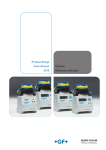
Download Connexion Red and Green electrofusion control units
Transcript
Caldervale Technology Ltd
Operating instructions and
specifications for
CONNEXION
Electrofusion Welding Unit
Helping you make the right connectionsTM
Models covered by this manual:
Connexion Red
Connexion Green
2
Index.
Specifications ............................................ 4
Warnings .................................................. 5
Electrofusion & Portable Generators………… 6
Instructions for use ................................... 8
Entering the data logging information ......... 9
Bar code mode .......................................... 10
Manual mode ............................................ 12
Settings menu ........................................... 14
Error messages ......................................... 16
Downloading data to a USB flash drive ....... 19
Certificate of conformity............................. 20
Certificate of calibration ............................. 20
Warranty information................................. 21
☺
!
?
Helpful information.
Important note.
Important operator input.
3
Specifications.
Operating mode:
Bar Code (Red unit only);
Manual Time Entry
(Two selectable manual time entry modes 0 to 999 second option or
1000 to 4000 second option);
Data log memory:
Memory download:
1000 welds
USB Flash Drive
Languages:
English (others available on request)
Input voltage nominal:
(± 20%)
110 V ac (88 to 132) or
220 V ac (184 to 276)
Input frequency:
(± 20%)
50 Hz (40 to 70)
Output voltage:
39.5 V ac true rms (default)
(10 to 48 Vac selectable in manual mode)
(8 to 48 Vac in bar code mode)
Output stability:
+/- 1.5%
Output current:
(continuous)
1 A to 60 A
Output power:
40 W to 2370 W
Power factor:
Apparent 0.72
Input power:
100 VA to 3300 VA
Input current:
1 A to 30 A with 110v input
1 A to 14 A with 230v input
Operating temperature:
-20°C to +45°C
Weight:
21 kg
Dimensions:
38,5 x 27,5 x 21.5cm
Protection level:
IP65
Protection class:
Class 1 (equipment must be earthed)
Caldervale Technology Ltd has a policy of continuous improvement in
product quality and design. Caldervale Technology Limited therefore
reserves the right to change the specification of its models at any time,
without prior notice and with impunity.
4
Warnings.
Important!
!
Information about the supply voltage for your welding
unit (110v or 230v) can be found on the front
instruction label. Please do not connect your unit to any
other supply voltage as damage may occur.
This manual outlines the operation, basic fault-finding and
maintenance of the electrofusion welding unit.
This manual forms a part of the product to which it relates. It
should be kept for the life of the product. Any amendments
issued by Caldervale Technology Limited should be
incorporated in the text. The manual should be passed to any
subsequent holder or user of this product.
This electrofusion welding unit is designed for use with 39.5v
manual electrofusion fittings with a maximum continuous
current requirement of 60A, and bar coded electrofusion
fittings.
Risk of explosion!. This equipment is not to be used in a
gaseous atmosphere.
Caution.
Risk of electric shock! Do not open.
Caution.
To avoid damage to the welding unit do not interrupt the input
supply or disconnect the output lead from the welding unit or
fitting during a fusion cycle.
Caution.
This apparatus must be earthed (grounded).
5
☺
222Electrofusion & Portable Generators22.
Electrofusion units are designed to provide a stable regulated
voltage for a period of time to an electrofusion fitting. This is
done by taking the mains voltage (or that from a portable
generator) and reducing it to a lower level by ‘cutting out’ part
of the voltage using the electronic circuitry inside the
electrofusion unit.
This reduction in the voltage has strange effects with the
overall power of the system. Even though this part of the
power has been cut out and is not used for welding the fitting,
it still has to be supplied by the generator. This means that the
total power taken from the generator is equal to the real power
needed to weld the fitting plus the cut out power from the
electronic circuitry.
Total power supplied = Real welding power + lost ‘cut out’ power
This effect where the input power to the machine is different to
the output power is called an ‘apparent power factor’. In simple
terms this power factor can be thought of as a mark of how
efficiently the machine uses the input power. If the power
factor is 1 then the machine is ‘100% efficient’. If the power
factor is 0.5 then the machine is ‘50% efficient’.
Electrofusion machines have a power factor of 0.75, this means
that they could be said to be 75% efficient.
Portable generators are designed to supply power evenly over
all the voltage waveform. If power is taken unevenly as with an
electrofusion machine, then generators start to have problems.
The electrofusion machine will actually only take power from
the generator for 75% of the time, the other 25% is the lost
‘cut out’ power. This power is taken every cycle of the
waveform, 50 cycles a second (Hz).
6
This ‘full power’ then ‘no power’ then ‘full power’ then ‘no
power’ effect causes great problems with the generator’s
alternator. These alternators are designed to give power evenly
through the cycles. This uneven power take up causes the
properties of the alternator, that actually produce the voltage,
(the magnetic fields) to break down. This causes the rated
power of the generator to drop sharply.
A good quality generator will be designed to work with
machines that have a power factor as low as 0.7 or 0.8 ,
meaning that the electrofusion machines will work OK.
However, these generators need more complicated alternators
that are more expensive to manufacture.
Cheaper generators will sacrifice the quality of the alternator in
favour of price. This means that they are only capable of
working with machines that have a power factor of 0.9 or 1. In
this case, the generators will not work with the electrofusion
machines.
When specifying generators for use with electrofusion, it is very
important not only to get the right power, 3kW, but also to get
a generator that will work with equipment that has a power
factor of 0.75. Generator manufacturers know what power
factors their equipment will work with so they will be able to
supply generators that work, if a little more expensive.
!
!
Do not start the generator with the electrofusion
control unit plugged in.
!
Do not stop the generator with the electrofusion
control unit plugged in.
Start the generator with no load connected.
Allow the generator to stabilize (run unloaded)
for a minute before connecting the electrofusion
unit.
7
Instructions for use.
Connect the welding unit to a good quality power source of the
correct voltage and capable of supplying at least 3 kW.
Turn the unit on with the rocker switch mounted on the side of
the case.
The unit will power up and show a Welcome Screen.
The unit will then display the Software Version Number, the
Product Code, Serial Number and Calibration date.
If the calibration of the unit has expired then a warning
message will be displayed. It is recommended that you return
the welding unit to Caldervale Technology Limited or one of
their approved repair agents for service and calibration if this
message is shown.
The display will now show the Owners Information.
All error messages will be displayed as they are detected. A list
with explanation of these is detailed further on in this manual.
-
A note on data entry.
☺
Use the UP and DOWN arrow buttons to change the
displayed information. Use the START button to accept
information or move forward. Use the STOP button to
reject information or move backward.
8
Entering the Data Logging Information.
The display will now ask if you want to turn on data logging.
This will record information about the operator, the fitting, and
the welding parameters. Use the Up and Down arrows to scroll
through Yes and No. When the required option is shown, press
the Start button to select it.
!
The selected data logging mode will continue for all
welds carried out until the unit is switched off. On
power up, the data logging question will be asked
again.
If you turn data logging on, then the display will ask for an
Operator Name. Use the Up and Down arrow buttons to change
the selected character and the Start button to accept it. Once
the name has been entered press the Start button again to
accept it all. (Maximum 16 characters.)
The display will now ask for a Location. Enter this in the same
way (maximum 16 characters).
The display will ask for a Job Reference. Enter this in the same
way (maximum of 16 characters).
The display will ask if the pipe has been scraped and the fitting
has been clamped. Use the Up and Down arrow buttons to
scroll through Yes and No. Select the required option.
When data logging has been turned on, welding parameters
such as the time, voltage, current, fitting resistance will be
recorded and saved to the memory. In bar code mode,
Traceability bar codes can also be entered. (A maximum of
three for every weld.)
?
The display will now ask you to select the mode of
operation. Use the Up or Down arrow buttons to scroll
through ‘Bar Code’, ‘Semi Auto’, ‘Manual’ and ‘Settings’.
Press Start when the required option is shown.
9
Bar Code Mode. (Red unit only)
If data logging has been enabled then the display will ask you
to read the Traceability bar codes from the components being
joined together. You can read a maximum of three codes for
each weld. When the codes have been read, press the Start
button.
The display will ask you to connect a fitting to the output leads.
Once this has been done, the unit will check the fitting
connection and ask for the welding bar code to be read.
When the bar code has been read, the unit will check the fitting
resistance matches the bar code information.
!
If a bar code from a different type of fitting to the one
connected to the output lead is read, then the unit will
detect that the fitting resistance is different and it will
not allow the unit to weld. This is a safety feature to
prevent mis-matched bar codes being read.
Information about the connected fitting will be displayed. The
welding time and voltage will be set automatically. Press the
Start button to begin welding.
The total weld time and the remaining weld time will be
displayed. This will count down to zero. During the weld, the
unit monitors the voltage and current and any faults will be
displayed.
At the end of the weld, the current weld number will be
displayed along with a ‘Cooling Time’.
☺
The cooling time is shown to help the operator. It is not
set from the bar code and it will continue to count up
until the Start button is pressed. It acts like a
stopwatch and is designed to tell the operator how long
ago the weld ended. This information is NOT recorded
in the data log.
10
The display will ask you to disconnect the fitting from the
output lead.
A ‘Repeat Last Type’ message will now be displayed. Use the
Up and Down arrow buttons to scroll through Yes and No, and
press Start to select your choice.
This option is designed to speed up the welding operation. If
Yes is selected then bar code mode will automatically be
selected again and the display will ask for the bar codes to be
read in. If No is selected then the display will ask you to select
the mode of operation.
!
The ‘Repeat Last Type’ screen can be enabled and
disabled in the Settings menu.
-
11
Manual Mode.
The display will ask you to connect a fitting to the output leads.
Once this has been done, the unit will check the fitting
connection and ask for the required time range to be selected,
press the Up arrow to select 0 to 999 secs then press the Start
button or press the Down arrow to select the range 1000 to
4000 secs then press the Start button.
Use the Up and Down arrow buttons to select the welding time.
Press the Start button to accept the displayed time.
Press the Start button to begin welding.
The total weld time and the remaining weld time will be
displayed. This will count down to zero. During the weld, the
unit monitors the voltage and current and any faults will be
displayed.
At the end of the weld, the current weld number will be
displayed along with a ‘Cooling Time’.
☺
The cooling time is shown to help the operator. It is not
set from the fitting information and it will continue to
count up until the Start button is pressed. It acts like a
stopwatch and is designed to tell the operator how long
ago the weld ended. This information is NOT recorded
in the data log.
The display will ask you to disconnect the fitting from the
output lead.
12
A ‘Repeat Last Type’ message will now be displayed. Use the
Up and Down arrow buttons to scroll through Yes and No, and
press Start to select your choice.
This option is designed to speed up the welding operation. If
Yes is selected then the unit will use the same parameters from
the last fitting. You will not be asked to enter the time and
voltage. The display will ask you to connect a fitting and then
ask you to press Start to begin the welding. If No is selected
then the display will ask you to select the mode of operation.
!
The ‘Repeat Last Type’ screen can be enabled and
disabled in the Settings menu.
-
13
Settings Menu.
Some of the operating parameters for the unit can be altered
from this menu. Some can be accessed by anybody, others
require you to enter a ‘Supervisor Password’. Use the Up and
Down arrow buttons to scroll through the options and press the
Start button to select it.
!
The Supervisor Password has a default value of 0000.
This can be changed through one of the menu options.
Clock
Use this option to set the clock. This is in 24 hour format as
HH:MM.
Date
Use this option to set the date. The format is DD-MM-YYYY.
Diagnostic
If there is a fault with the unit, then this option will set the unit
to carry out diagnostic checks the next time it carries out a
weld. This will log specific information to help repair it. Please
contact Caldervale Technology Limited for full information on
this option.
-
14
Other password protected settings
Repeat Last Type
This can be turned on (default) or off.
Data Logging
The data logging can be set to be always on, always off, or to
ask each time the unit is switched on (default).
Language
The display language can be set. The default value is English.
Password
The Supervisor password can be changed.
Calibration
Calibration mode can be entered from here.
Change owner name
The owner details displayed at power up can be changed from
here.
-
15
Error Messages.
E00 Good weld
E01 Supply voltage low.
The supply voltage is more than 20% lower than the nominal
value. Check the supply.
E02 Supply voltage high.
The supply voltage is more than 20% higher than the nominal
value. Check the supply.
E03 Supply frequency low.
The supply frequency is less than 40 Hz. Check the supply.
E04 Supply frequency high.
The supply frequency is greater than 70 Hz. Check the supply.
E05 Output voltage low.
The output voltage is more than 1½% lower than the nominal
value. Check the power supply to the welding unit has sufficient
capacity.
E06 Output voltage high.
The output voltage is more than 1½% higher than the nominal
value. Possible fault within the welding unit.
E07 Excessive output voltage.
The output voltage is more than 6% higher than the nominal
value. Possible fault within the welding unit.
E08 Fitting connection fault.
An open circuit in the output has been detected while a weld is
in progress. Check the fitting and output leads.
16
E09 Output current low.
The output current is less than 2 amps. Check the fitting and
the output lead connections.
E10 Case temperature too high.
The case temperature is too high. Disconnect the unit from the
supply and allow it to cool down before reconnecting it.
E11 Operator stop.
The operator has interrupted the welding process by pressing
the Stop button.
E12 Self test error – Stuck button.
During the power up self test, the unit has detected that a
button was pressed or is stuck in.
E13 Self test error – Output fault.
During the power up self test, the unit has detected a voltage
on the output terminals. This indicates a fault within the unit.
E14 Self test error – Calibration error.
During the power up self test, the unit has detected that the
unit requires calibration.
E15 Internal temperature error.
The internal temperature of the unit is too high. Disconnect the
unit from the supply and allow it to cool down before
reconnecting it.
E16 Power relay error.
The power relays have not activated. This indicates a fault
within the unit.
E17 Current surge.
The output current has increased over time indicating a fault
with the fitting.
17
E18 USB memory disc full.
The USB memory disc has not got sufficient free space for the
records held in the control unit to be downloaded.
E127 Loss of supply.
The supply has been lost during the fusion cycle.
Note: this will only be recorded on the fusion joint record.
!
Maintenance.
This equipment contains no user-serviceable parts. It is
recommended that the welding unit and accessories
should be returned to Caldervale Technology Ltd
annually for checking and calibration.
18
Downloading data to a USB Flash Drive.
The data log memory is transferred to a computer by using a
USB Flash Drive. This drive connects to the external USB socket
on the back of the welding unit (where the bar code pen fits on
a Red unit). The data is downloaded as a Microsoft Excel
spreadsheet (.XLS). This USB drive can then be plugged into
any computer capable of recognising USB1.1 devices. When
plugged in, this will act like a drive on the computer and the
downloaded file can be opened (in Excel), saved or deleted.
☺
The USB Flash Drive will act like any other disk drive on
a computer. When full, files will have to be deleted to
make space. As with other drives, occasionally it will
require defragmenting. Please see your computer help
files for information on this.
The unit will only display information to download data to the
USB flash drive when it is plugged into the unit. This can be
done before the unit is switched on, or anytime up to and
including where the display is asking if the data log should be
turned on or off.
When the unit detects a USB flash drive, the display will ask if
you want to download the data. If you select Yes, the data will
be transferred. It will then ask if you want to clear the data log.
If you select Yes then all the stored information in the welding
unit will be deleted. The information will still be stored in the
USB drive.
!
The welding unit can not delete files from the USB flash
drive. This must be done from a computer.
-
19
Certificate of conformity
This product has been manufactured in accordance with the following
directives:
• 73/23/EEC Low voltage – Electrical Equipment (Safety) Regulations.
• 89/336/EEC Electromagnetic Compatibility Regulations.
• 2002/95/EC Restriction of the use of Certain Hazardous Substances in
Electrical and Electronic Equipment Regulations.
• 2002/96/EC Waste Electrical and Electronic Equipment (WEEE) Directive.
This product has been manufactured to meet the following standards:
Safety of Electrical Products:
•
•
•
•
•
•
ISO 12176-2 Equipment for fusion jointing polyethylene systems. Part 2 :
Electrofusion.
Italian National Standard UNI 10566
BS 7540-1,2 & 3:2005, BS 7671:2001, BS 7919:2001, BS EN 1555-3:2002,
BS EN 60068-2:1993, BS EN 60204-1:2004, BS EN 60309-2:1999,
BS EN 60529:1992, BS EN 60947-1:2004, BS EN 61558-1:1998,
BS EN 61558-2 &23:2001, BS EN 62262:2002
Electromagnetic Compatibility:
•
•
BS EN 61000-6-1:2001, BS EN 61000-6-2:2001
BS EN 61000-6-3:2001, BS EN 61000-6-4:2001
Contact Caldervale Technology Ltd for
disposal advice of this equipment.
Certificate of calibration.
• This product has been inspected and tested in accordance with the
ISO9001 quality control systems and procedures in place at
Caldervale Technology Limited, Dewsbury.
• This product has been calibrated using equipment traceable to
national and international standards, by a NAMAS (National
Accreditation of Measurement and Sampling) accredited laboratory.
NAMAS is a service of UKAS (United Kingdom Accreditation
Service).
• This product has a twelve month calibration period, active from the
date of purchase by the end-user.
20
Warranty Information.
1.
Extent of Warranty.
(a)
Subject to clauses 2 and 3, Caldervale Technology Limited
warrants to the end-user customer that its products will be free
from defects in materials and workmanship, for one year after the
date of purchase by the end-user customer, subject to providing
proof of purchase.
If Caldervale Technology Limited receives, during the warranty
period, notice of a defect in product which is covered by this
warranty, Caldervale Technology Limited shall either repair or
replace the product, at its option. Any replacement product may be
either new or like-new, provided that it has functionality at least
equal to that of the product being replaced.
All warranty work will be carried out by Caldervale Technology
Limited unless otherwise agreed. On-site warranty and repair or
replacement services are available from authorised Caldervale
Technology Limited service facilities world-wide.
Customers shall prepay shipping charges for products returned to
Caldervale Technology Limited for warranty service, and Caldervale
Technology Limited will charge for return of the products back to
the customer.
This warranty statement gives the customer specific legal rights.
The customer may also have other rights which vary from country
to country in the world.
(b)
(c)
(d)
(e)
2.
Pre-conditions for Warranty Application.
Caldervale Technology Limited’s warranty covers only those defects
which arise as a result of normal use of the product, and this warranty
shall only apply in the following circumstances:
(a)
(b)
(i)
(ii)
(iii)
(iv)
(v)
All the instructions contained in the operating manual have been
complied with; and
None of the following apply:
Improper or inadequate maintenance;
Unauthorised modification, misuse or any use not in accordance
with the operating manual and good industry practice:
Operation outside the products specifications, including duty cycle
abuse, and input power abuse;
Improper site preparation or maintenance; and
Faulty pipe or fitting.
21
3.
Limitations of Warranty.
(a)
Caldervale Technology Limited does not warrant the operation of
any product to be uninterrupted or error free.
Caldervale Technology Limited makes no other warranty of any
kind, whether express or implied, with respect to its products.
Caldervale Technology Limited specifically disclaims the implied
warranties of satisfactory quality and fitness for a particular
purpose.
To the extent that this warranty statement is inconsistent with the
law of the locality where the customer uses the product, this
warranty statement shall be deemed modified by the minimum
necessary to be consistent with such local law.
To the extent allowed by local law, the remedies provided in this
warranty statement are the customer’s sole and exclusive
remedies.
This control unit has been designed to weld the range of fittings
available at the time of its design and development. Caldervale
Technology Limited can accept NO liability for the units ability or
otherwise to weld new or different fittings that subsequently
appear in the market place.
(b)
(c)
(d)
(e)
Please complete this information and keep it safely with
your proof of purchase receipt. You will require it for
any warranty claim.
Where purchased
..............................................................
Date of purchase
..............................................................
Name & address
of purchaser
..............................................................
..............................................................
..............................................................
..............................................................
..............................................................
..............................................................
Type of unit
..............................................................
Serial number
..............................................................
22
For Service and repair please contact:
Caldervale Technology Limited
Bretfield Court
Dewsbury
West Yorkshire
WF12 9DB
United Kingdom
Tel: +44 (0)1924 469571
Fax: +44 (0)1924 460951
[email protected]
http://www.caldertech.com
© 2007 Rev 14-08-2007
Helping you make the right connectionsTM
23


