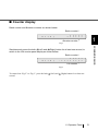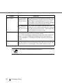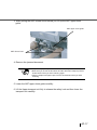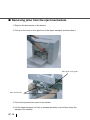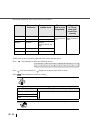
1
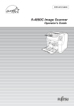
P3PC-1682-01EN
fi-4860C2 Image Scanner
Installation Guide
INTRODUCTION
Thank you for purchasing the fi-4860C2 Duplex Color Scanner.
The fi-4860C2 is an image scanner designed to scan documents in large quantities.
The fi-4860C2 has the following features.
High speed, high quality color scanning capabilities
Scans documents of Letter and A4 size at the speed of 60ppm/120ipm
@200dpi.
Highly reliable document handling
Accepts various thicknesses, sizes and types of documents.
Production ready
High capacity hopper (500sheets, 20lb(80 g/m2) Letter or A4 size) with
Imprinter options.
About this manual
The contents of this manual are as follows.
1. SCANNER BASICS
This chapter describes the contents of the scanner package, part names, and
operator panel operation.
2. INSTALLATION AND CONNECTIONS
This chapter describes how to install and connect the scanner to a PC, and how
to install the scanner application software.
The “Operator’s Guide” is also stored on the “User Manual CD-ROM”.
The guide includes operation and daily care for the scanner, replacing of consumbles,
solutions for troubles, etc.
In addition to this guide (Installation Guide), please also read the Operator’s Guide.
See next page for the contents of the Operator’s Guide.
The “FUJITSU TWAIN32 Scanner Driver User’s Guide” is stored on the “Setup CDROM”. Please also read the Scanner Driver User’s Guide.
●i
The contents of the Operator’s Guide is as follows:
1. BASIC SCANNER OPERATIONS
This chapter describes basic scanner operations including basic document
scanning.
2. SCANNING VARIOUS TYPES OF DOCUMENTS
This chapter describes how to scan various type of documents.
3. DAILY CARE
This chapter describes how to clean the scanner.
4. REPLACEMENT OF CONSUMABLES
This chapter describes how to replace scanner consumables.
5. SOLVING COMMON PROBLEMS
This chapter describes how to remedy document jams, other troubles, items to
check before contacting the agent where you bought the scanner, and how to
check device labels.
6. ADF DOCUMENT SPECIFICATIONS
This chapter describes the types of documents which can be scanned with this
scanner.
7. OPERATOR PANEL MENUS
This chapter describes Setup-mode and Test-mode.
8. OPTIONS
This chapter describes the options available for the scanner.
9. SCANNER SPECIFICATIONS
This chapter lists the scanner specifications.
We hope that this manual is useful in taking full advantage of the fi-4860C2
Duplex Color Scanner's capabilities.
●ii
■ Regulatory Information
FCC Regulations
This equipment has been tested and found to comply with the limits for a Class B digital
device, pursuant to Part 15 of the FCC Rules. These limits are designed to provide
reasonable protection against harmful interference when the equipment is operated in a
commercial environment. This equipment generates, uses, and can radiate radio frequency
energy and, if not installed and used in accordance with the instruction manual, may cause
harmful interference to radio communications. However, there is no guarantee that
interference will not occur in a particular installation. If this equipment does cause harmful
interference to radio or television reception, which can be determined by turning the
equipment off and on, the user is encouraged to try to correct the interference by one or
more of the following measures:
•Reorient
or relocate the receiving antenna.
•Increase
the separation between the equipment and receiver.
•Connect
the equipment into an outlet on a circuit different from that to which the
receiver is located.
•Consult
your deealer or an expeerienced radio/TV technician.
FCC warning: Changes or modifications not expressly approved by the party responsible
for compliance could void the user’s authority to operate the equipment.
ATTENTION
•
The use of a shielded interface cable is required to comply
with the Class B limits of Part 15 of FCC rules. The length of
the SCSI interface cable must be 1.5 meters (5 feet) or less.
•
The length of the AC cable must be 3 meters (10 feet) or
less.
●iii
Canadian DOC Regulations
This digital apparatus does not exceed the Class B limit for radio noise emissions from
digital apparatus set out in the Radio interference Regulations of the Canadian Department
of Communications.
Le présent appareil numérique n'émet pas de parasites radioélectriques dépassant les limites
applicables aux appareils numériques de la classe B et prescrites dans le Règlement sur le
brouillage radioélectrique dictées par le Ministère des Communications du Canada.
Cet appareil numérique de la classe B est conforme à la norme NMB-003 du Canada.
Bescheinigung des Herstellers / Importeurs
Für den fi-4860C2 wid folgendes bescheinigt:
• In
Übereinsstimmung mit den Bestimmungen der EN45014(CE) funkentstört
• Maschinenlärminformationsverordnung 3.GPSGV: Der höchste
Schalldruckpegel beträgt
70 dB (A) oder weniger, gemäß EN ISO 7779.
International ENERGY STAR® Program
As an ENERGY STAR® Partner, PFU LIMITED has determined
that this product meets the ENERGY STAR® guidelines for
energy efficiency.
The International ENERGY STAR® Office Equipment Program is
an international program that promotes energy saving through the
penetration of energy efficient computers and other office
equipment. The program backs the development and dissemination
of products with functions that effectively reduce energy
consumption. It is an open system in which business proprietors can participate voluntarily.
The targeted products are office equipment such as computers, monitors, printers,
facsimiles, copiers, scanners, and multifunction devices. Their standards and logos are
uniform among participating nations.
This product meet the ENERGY STAR® guidelines of Japan and U.S.
●iv
Use in High-safety Applications
This product has been designed and manufactured on the assumption that it will be used in
office, personal, domestic, regular industrial, and general-purpose applications. It has not
been designed and manufactured for use in applications (simply called "high-safety
applications" from here on) that directly involve serious danger to life and health when an
extremely high degree of safety is required, for example, in the control of nuclear reactions
at nuclear power facilities, automatic flight control of aircraft, air traffic control, operation
control in mass-transport systems, medical equipment for sustaining life, and missile firing
control in weapons systems, and when provisionally the safety in question is not ensured.
The user should use this product with adopting measures for ensuring safety in such highsafety applications. PFU LIMITED assumes no liability whatsoever for damages arising
from use of this product by the user in high-safety applications, and for any claims or
compensation for damages by the user or a third party.
About the use of mercury
Hg
Lamp(s) inside this product contain mercury and must be recycled or
disposed of according to local, state, or federal laws.
To avoid unexpected injuries:
•Do
not put the substance in the lamp in your mouth as it contains mercury.
•Do
not breathe the chemical liquid contained in the scanner lamps.
•Do
not incinerate, crush, or shred the lamps or scanner parts.
Illegal Copying
Reproducing bills, coins, government securities and passports, licenses issued by public
author or civilian organizations, official documents, private paper is illegal and and subject
to punishment.
Copyrighted Material
Literary works like books, paintings, wood block prints, maps, drawings, and photographs
should not be reproduced without the rightful person’s permission.
●v
Trademarks
Microsoft, Windows and Windows NT are registered trademarks of Microsoft Corporation
of the USA and other respective countries.
ISIS, QuickScan and their respective logos are trademarks or registered trademarks of EMC
Corporation in the United States.
Adobe, the Adobe logo, and Acrobat are either registered trademarks of Adobe Systems
Incorporated in the United States and/or other countries.
Other product names are the trademarks or registered trademarks of the respective
companies.
How Trademarks Are Indicated In This Manual
References to operating systems (OS) are indicated as follows:
Windows 95:
Microsoft® Windows® 95 operating system.
Windows 98:
Microsoft® Windows® 98 operating system.
Windows Me:
Microsoft® Windows® Millennium Edition operating system.
Windows NT 4.0:
Microsoft® Windows NT® 4.0 Server operating system, Microsoft®
Windows NT® 4.0 Workstation operating systemoperating system
Windows 2000:
Microsoft® Windows® 2000 Professional operating system.
Windows XP:
Microsoft® Windows® XP Professional operating system, and
Microsoft® Windows® XP Home Edition operating system.
Where there is no distinction between the different versions of the above operating system,
the general term "Windows " is used.
Manufacturer
PFU LIMITED
International Sales Dept., Imaging Business Division, Products Group
Solid Square East Tower, 580 Horikawa-cho, Saiwai-ku,
Kawasaki-shi Kanagawa 212-8563, Japan
Phone : (81-44) 540-4538
All Rights Reserved, Copyright© PFU LIMITED 2006.
●vi
■ Note, Liability
READ ALL OF THIS MANUAL CAREFULLY BEFORE USING THIS PRODUCT.
IF NOT USED CORRECTLY, UNEXPECTED INJURY MAY BE CAUSED TO USERS
OR BYSTANDERS.
Also, store this manual in a convenient and safe place so that it can be easily referred to
during use of this product.
While all efforts have been made to ensure the accuracy of all information in this manual,
PFU LIMITED assumes no liability to any party for any damage caused by errors or
omissions or by statements of any kind in this manual, its updates or supplements, whether
such errors are omissions or statements resulting from negligence, accidents, or any other
cause. PFU LIMITED further assumes no liability arising from the application or use of any
product or system described herein; nor any liability for incidental or consequential
damages arising from the use of this manual. PFU LIMITED disclaims all warranties
regarding the information contained herein, whether expressed, implied, or statutory.
PFU LIMITED reserves the right to make changes to any products herein, to improve
reliability, function, or design, without further notice and without obligation.
●vii
■ Preface
Safety Precautions
This manual describes important details for ensuring the safe and correct use of this product.
Thoroughly read this manual before you start to use this product. In particular, be sure to
read and fully understand the Safety Precautions described in this manual before you use
this product.
Also, store this manual in a convenient and safe place so that it can be easily referred to
during use of this product.
Warning Indications Used In This Manual
This manual uses the following indications to ensure safe and correct use of this product,
and to prevent possible danger and injury to the operator and other persons.
WARNING
CAUTION
●viii
This indication alerts operators to an operation that, if not
strictly observed, may result in severe injury or death.
This indication alerts operators to an operation that, if not
strictly observed, may result in safety hazards to personnel or
damage to equipment.
Symbols Used In This Manual
This manual uses the following symbols in explanations in addition to warning indications.
ATTENTION
This symbol alerts operators to particularly important information. Be sure
to read this information.
This symbol alerts operators to helpful advice regarding operation.
HINT
A TRIANGLE symbol indicates that special care and attention is required.
The drawing inside the triangle shows the specific caution.
A CIRCLE with a diagonal line inside shows action which users are not
allowed to do.
The drawing inside or under the circle shows the specific action that is not
allowed.
R
Outline characters on a colored background shows instructions users
should follow.
It may include the drawing which shows the sepecific instruction.
Screen Examples In This Manual
The screen examples in this manual are subject to change without notice in the interest of
product improvement.
If the actual displayed screen differs from the screen examples in this manual, operate by
following the actual displayed screen referring to the User's Manual of the scanner
application you are using.
Furthermore, the screenshots in this manual are for the FUJITSU TWAIN32 scanner driver
and ScandAll 21 image capturing software, FUJITSU ISIS scanner driver, QuickScan™
image capturing software and Adobe® Acrobat®.
●ix
About Maintenance
The user must not perform repairs on this scanner. Contact the store where you purchased
the scanner or an authorized FUJITSU Image Scanner service provider to make repairs to
this product.
■ Safety Precautions
WARNING
The following describes important warnings described in this manual.
Do not touch the AC cable with wet hands.
Do not touch the power plug with wet hands. Doing so might cause electric
shock.
Do not damage the AC cable.
A damaged AC cable may cause fire or electric shock.
Do not place heavy objects on AC cables, or pull, bend, twist, heat,
damage or modify AC cables.
Also, do not use damaged AC cables or power plugs, and AC cables or
power plugs when the wall socket is loose.
Use only specified AC cables and connector cables
Use only specified AC cables and connector cables. Failure to use the
correct cables might cause electric shock and equipment failure.
●x
Use this scanner only at the indicated power voltage. Do not connect
to multiple-power strips.
Use this scanner only at the indicated power voltage and current.
Improper power voltage and current might cause fire or electric shock.
Also, do not connect to multiple-power strips.
Wipe any dust from the power plug.
Wipe off any dust from metal parts on the power plug or metal fittings with
a soft, dry cloth. Accumulated dust might cause fire or electric shock.
Do not install the device in locations subject to oil smoke, steam,
humidity, and dust.
Do not install the scanner in locations subject to oil smoke, steam,
humidity, and dust. Doing so might cause a fire or electric shock.
Do not use the scanner if you smell strange odor.
If you detect heat coming from the device or detect other problems such
as smoke, strange smells or noises, immediately turn off the scanner and
then disconnect its power plug.
Make sure that the smoking has stopped, and then contact the store
where you bought the scanner or an authorized FUJITSU scanner service
provider.
●xi
Turn the scanner OFF if it is damaged.
If the scanner is damaged for any reason, turn off the scanner and unplug
the power cable before contacting the store where you purchased the
scanner.
Do not put liquids inside the scanner.
Do not insert or drop metal objects in to the scanner. Do not scan wet
documents or document with paper clips or staples. Do not splash or allow
the scanner to get wet.
If foreign objects (water, small metal objects, liquids, etc.) get inside the
scanner, immediately turn off the scanner and disconnect the power plug
from the power outlet, then contact the store where you bought the scanner or the Maintenance Service Center. Pay particular attention to this
warning in households where there are small children.
Do not touch the inside of the scanner unless necessary.
Do not take apart or modify the scanner. The inside of the scanner
contains high-voltage components. Touching these components might
cause fire or electric shock.
●xii
CAUTION
The following describes important cautions described in this manual.
Do not install the scanner on unstable surfaces.
Install the scanner on a desk or table so that none of its parts protrude
outside of the desktop. Also, make sure that the scanner is installed on a
flat, level surface. Do not install the scanner on unstable surfaces. Install
the scanner on a level surface that is free of vibration to prevent it from
falling.
Install the scanner on a strong surface that will support the weight of the
scanner and other devices.
Firmly insert the power plug.
Firmly insert the power plug into the power outlet as far it can go.
Do not block the ventilation ports.
Do not block the ventilation ports. Blocking the ventilation ports generates
heat inside of scanner, that may results in fire or scanner failure.
Do not place heavy objects or stand on top of the scanner.
Do not place heavy objects on the scanner or use the scanner's top
surface for performing other work. Improper use might cause injuries.
●xiii
Before moving the scanner, disconnect the power plug from the power
outlet.
Do not move the scanner with the power and interface cables connected
as this might damage the cables, causing fire, electric shock or injuries.
Before moving the scanner, be sure to disconnect the power plug from the
power outlet, and disconnect data cables. Also, make sure that the floor is
free of obstructions.
Protect the scanner from static electricity.
Install the scanner away from strong magnetic fields and other sources of
interference. Also, protect the scanner from static electricity as this might
cause the scanner to malfunction.
Do not use aerosol sprays near the scanner.
Do not use aerosol sprays to clean the scanner. Aerosol sprays cause dirt
and dust to enter the scanner, resulting in scanner failure and malfunction.
Avoid any contact when scanner is in use.
Avoid touching any part of the scanner mechanism or paper when the
scanner is operating as this may cause injuries.
●xiv
Disconnect the power plug from the power outlet when the scanner is
not used for a long period of time.
When the scanner is not used for a long period of time, be sure to
disconnect the power plug from the power outlet for safety.
Do not install the scanner in the direct sunlight.
Do not install the scanner in the direct sunlight or near heating apparatus.
Doing so might cause excessive heat to build up inside the scanner,
causing fire or scanner trouble. Install the scanner in a well-ventilated
location.
Do not try to move or lift the scanner alone.
This scanner is heavy (99lbs/45kg). When you lift the scanner, ensure that
additional personnel are used.
●xv
■ Fujitsu Group Offices
Please send your comments on this manual or on Fujitsu products to the following
addresses:
FUJITSU COMPUTER PRODUCTS OF
AMERICA, INC.
●xvi
FUJITSU CANADA, INC.
1255 East Arques Avenue Sunnyvale,
CA 94085-4701, U.S.A.
Phone: (1-408)746-7000
Technical Assistance Center:
(1-800)626-4686
Fax: (1-408)746-6910
Website: http://www.fcpa.fujitsu.com/
E-mail: [email protected]
6975 Creditview Road Unit 1
Mississauga, On L5N 8E9 Canada
Phone: (1-905)286-9666
Fax: (1-905)286-5988
Website: http://www.fujitsu.ca/
E-mail: [email protected]
(For Sales Questions)
[email protected]
(For technical questions)
FUJITSU EUROPE LTD.
FUJITSU DEUTSCHLAND GmbH.
Hayes Park Central, Hayes End Road,
Hayes Middlesex UB4 8FE, U.K.
Phone: (44-208)573-4444
Fax: (44-208)573-2643
Website: http://www.fel.fujitsu.com/
Frankfurter Ring 211, 80807 München,
Germany
Phone: (49-89)323-78-0
Fax: (49-89)323-78-100
Website: http://www.fdg.fujitsu.com/
E-mail: [email protected]
FUJITSU ITALIA S.p.A.
FUJITSU ESPAÑA Services, S.A.U.
Via Nazario Sauro, 38
20099 Sesto San Giovanni (MI), Italy
Phone: (39-02)26294.1
Fax: (39-02)26294.201
Website: http://www.fis.fujitsu.com/
E-mail: [email protected]
Camino Cerro de los Gamos, 1 28224,
Pozuelo de Alarcon, Madrid, Spain
Phone: (34-91)784-9000
Fax: (34-91)784-9379
Website: http://es.fujitsu.com/
E-mail: [email protected]
FUJITSU AUSTRALIA LTD.
FUJITSU ASIA PTE.LTD.
Fujitsu House 2 Julius Avenue
North Ryde, N.S.W 2113 Australia
Phone: (61-2)9776-4555
Fax: (61-2)9776-4024
Website: http://au.fujitsu.com/
20 Science Park Road, #03-01, Tele Teck
Park Singapore Science Park II, Singapore
117674
Phone: general (65)6512-7555
query (65)6512-7431
Fax: (65)6512-7499
Website: http://www.fapl.fujitsu.com
E-mail: [email protected]
FUJITSU TAIWAN LTD.
FUJITSU HONG KONG LTD.
19th Fl., No39, Sec.1,Chung-hwa Rd.,
Taipei, Taiwan
Phone: (886-2)2311-2255
Fax: (886-2)2311-2277
Website: http://tw.fujitsu.com/
10/F., Lincoln House, 979 King's Road,
Taikoo Place, Island East, Hong Kong
Phone: (852)2827-5780
Fax: (852)2827-4724
Website: http://hk.fujitsu.com/
E-mail: [email protected]
FUJITSU SYSTEMS BUSINESS
(THAILAND) LTD.
FUJITSU KOREA LTD.
12th Fl., Olympia Thai Tower, 444
Rachadapisek Road, Samsennok,
Huay kwang, Bangkok 10310, Thailand
Phone: +66 (0) 2500-1500
Fax: +66 (0) 2500-1555
Website: http://th.fujitsu.com/
Susong Tower Building, 83-1
Susong-Dong, Jongno-Gu, Seoul,
Republlic of Korea
Phone: (82-2)3787-6159
Fax: (82-2)3787-6164
Website: http://kr.fujitsu.com/
E-mail: [email protected]
FUJITSU MALAYSIA SDN.BHD.
FUJITSU PHILIPPINES, INC
Level 1 & 2
3505 Jalan Teknokrat 5
63000 Cyberjaya
MALAYSIA
Phone: general (603)8318-3700
query (603)8318-3700 (ext 375)
Fax: (603)8318-8700
Website: http://www.fujitsu.com/my/
E-mail: [email protected]
2/F, United Life Building, 837 A. Arnaiz
Avenue (Pasay Road),
Legaspi Village, Makati City 1229,
Philippines
Phone: +63 (2) 812-4001
Fax: +63 (2) 817-7576
Website: http://ph.fujitsu.com
Imaging Business Division,
PFU LIMITED
PFU LIMITED
(Corporate headquarters)
Solid Square East Tower, 580
Horikawa-cho, Saiwai-ku, Kawasaki-shi,
Kanagawa 212-8563, Japan
Phone: (81-44)540-4658
Fax: (81-44)540-4639
Website:
http://imagescanner.fujitsu.com
E-mail: [email protected]
Nu 98-2 Unoke, Kahoku-shi,
Ishikawa 929-1192, Japan
Phone: (81-76)283-1212
Fax: (81-76)283-4689
●xvii
●xviii
CONTENTS
INTRODUCTION......................................................................................i
■ Regulatory Information...................................................... iii
■ Note, Liability ................................................................... vii
■ Preface............................................................................ viii
■ Safety Precautions.............................................................x
■ Fujitsu Group Offices ...................................................... xvi
1 SCANNER BASICS.............................. 1
Checking the Contents of the Scanner Package ..................2
Names and Functions of Parts .............................................3
Operator Panel .....................................................................6
2 INSTALLATION AND
CONNECTIONS ................................. 11
Installing the Scanner .........................................................12
Connecting the Scanner .....................................................13
Installing the Scanner Driver and Application .....................17
APPENDIX-1
MESSAGES OF OPERATOR PANEL ............ AP-1
APPENDIX-2
CONSUMABLES AND REPLACEMENT
CYCLE ........................................................... AP-14
APPENDIX-3
TROUBLESHOOTING .................................. AP-15
APPENDIX-4
CLEARING DOCUMENT JAMS ................... AP-16
INDEX
............................................................................IN-1
●xix
●xx
1
SCANNER BASICS
This chapter describes how to prepare the scanner before use.
1.1 Checking the Contents of the Scanner Package................2
1.2 Names and Functions of Parts.............................................3
1.3 Operator Panel.......................................................................6
1
1.1 Checking the Contents of the
Scanner Package
When you unpack the scanner package, make sure that all the following parts are included in the
package. If any parts are missing or defective, contact to the distributor where you purchased the
scanner from.
Please handle the scanner and the accessories with care.
Scanner and Accessories
Scanner
Power cable (x1)
(For european countries: x2)
Setup CD-ROM
Adobe® Acrobat® 7.0
CD-ROM
User Manual CD-ROM
Installation Guide
(This manual)
fi-X
XX
X XX
XX
XX
XX
X
FUJITSU TWAIN
Installation Guide
FUJITSU ISIS Installation
Guide
2
VRS installation
CD-ROM
1.1 Checking the Contents of the Scanner Package
1.2 Names and Functions of Parts
This section describes the names of parts and their functions.
■ Units
12
1
10
13
14
SCANNER BASICS
1
2
19
11
6
7
4
9
8
5
3
19
17
15
18
16
1.2 Names and Functions of Parts
3
No.
4
Name
Function
1
Operator panel
Used for operating the scanner.
2
Power button
Used to power the scanner on/off.
3
Hopper
Document input tray.
4
Side guides
Used for adjusting the document width.
5
Hopper extension
Used for long documents.
6
ADF (Automatic document feeder)
Feeds documents automatically.
7
Pick roller unit
Picks top page from document stack.
8
Guide plate
The pad assy is mounted on.
9
Pad Assy
Separates top page from document stack.
10
Upper transport unit
Opens for easy access.
11
Lever
Used to open the Upper transport unit.
12
Stacker
Document exit tray.
13
Stopper
Used to stop documents as they exit into the stacker.
14
Stacker extension
Used to support long documents.
15
Main line switch
Controls supply of line power to the scanner.
16
Power inlet
For the power cable connection.
17
Interface connector
For Ultra Wide SCSI connection.
18
Third party slot (TPS)
For installing an option board
19
Imprinter covers
Opens to access print cartridge for replacement.
1.2 Names and Functions of Parts
■ Assemblies
1
SCANNER BASICS
Lamp unit
Removable glass sheetguide
Lamp socket cover
Lamp
PAD Assy
Lamp
Lamp socket cover
Guide plate
Brake roller unit
Pick roller unit
1.2 Names and Functions of Parts
5
1.3 Operator Panel
(1) The operator panel is located at the Upper right hand side of the scanner. The
panel consists of an LCD display (16 characters x 2 line), LEDs, and buttons.
■ Arrangement
Power button
6
1.3 Operator Panel
■ Function of Buttons
Button
Name
Function
Turns on/off when the main line switch is set to “ | ”.
Send to/Start
1
Starts scanning in test mode.
Clears the error if this button is pushed while the Check lamp is on or is blinking.
Enter
Used for setup, or test mode.
Exit
Used for setup, or test mode.
Returns LCD display to “Ready” status.
Previous
SCANNER BASICS
Stop
Used for setup, or test mode.
Displays the previous menu item when this button is pushed.
Used for setup, or test mode.
Displays the next menu item when this button is pushed.
Next
Used for setup, or test mode.
Changes the setting of the selected item.
Used for setup, or test mode.
Changes the setting of the selected item.
1.3 Operator Panel
7
■ Function of LEDs
LED
Power
Function
Lights when the power supply is switched on.
(Green)
Read
Light during scanning.
(Green)
Check
Lights when a hardware alarm is detected.
Lights out when
button is pushed. (except initial errors)
(Yellow)
Blinks when an equipment error occurs.
Paper jam or Double feed is detected.
Press [Stop] button to clear the error, and the LED lights out.
In the case of Paper jam, when the document is removed, and the Upper
transport unit is closed, the LED lights out automatically.
■ Function of LCD panel
LCD
Function
Displays the scanner sutatus and error messages.
8
1.3 Operator Panel
■ Counter display
Batch counter and Abrasion counters are shown below:
Batch counter L
R
e
a
d
x
y
x
x
x
x
x
x
x
x
x
x
1
Abrasion counter K
Fig.1
SCANNER BASICS
Simultaneously press the both (Left) and (Right) button for at least one second, to
switch to the Life counter panel display as shown bellow:
Batch counter L
R
e
a
d
y
*
x
x
x
x
x
x
x
x
x
x
x
x
x
Life counter K
Fig.2
To return from “Fig.2” to “Fig.1”, press the both
second.
(Left) and
(Right) button for at least one
1.3 Operator Panel
9
Counter
Batch counter
Functions
(Left) button
is pressed for at
least one second.
The number of scanned documents from the start of
reading until "Paper empty" or an error is detected.
The counter is automatically reset at the start of
next reading. This counter can be used for checking
the number of scanned documents per batch.
(Right)button This counter is increased by one per sheet. The
counter is not re-initialized until the power is turned
is pressed for at
least one second. off. The counter can be used for checking the number of scanned documents per day.
Abrasion counter
The abrasion counter counts the accumulated number of scanned sheets.
This counter is increased by one per sheet scanned.
It is used for checking the cleaning cycle or the parts replacement cycle.
Refer to “Chapter7 OPERATOR PANEL MENUS of the Opelator’s
Guide” included in “User Manual CD-ROM” about how to reset this
counter.
Life counter
Keeps acumulative count of the total number of scans made by the scanner. This counter is increased by one per sheet and may be used to estimate of the device’s remaining life. This counter cannot be reset.
The counter is not displayed when the value is 0.
ATTENTION
10
1.3 Operator Panel
2
INSTALLATION AND
CONNECTIONS
This chapter describes how to install and connect the scanner to a PC, and
how to install the Fujitsu application software.
References to operating systems (OS) are indicated as follows:
Windows 95:
Microsoft® Windows® 95 operating system.
Windows 98:
Microsoft® Windows® 98 operating system.
Windows Me:
Microsoft® Windows® Millennium Edition
operating system.
Windows NT 4.0:
Microsoft® Windows NT® 4.0 Server operating
system, Microsoft® Windows NT® 4.0
Workstation operating systemoperating system
Windows 2000:
Microsoft® Windows® 2000 Professional
operating system.
Windows XP:
Microsoft® Windows® XP Professional operating
system, and Microsoft® Windows® XP Home
Edition operating system.
2.1 Installing the Scanner .........................................................12
2.2 Connecting the Scanner .....................................................13
2.3 Installing the Scanner Driver and Application..................17
11
2.1 Installing the Scanner
The following shows the procedure for installing the scanner.
■ Cautions on placement of scanner
1.
Move the scanner to the installation area.
Refer to the "Operator’s Guide" stored on the “User Manual CD-ROM” about
the dimensions of the scanner, and the space required for its installation.
ATTENTION
Move the scanner with more than two people as it weights approximately 99
lbs (45 Kg).
When you move scanner grab it at its bottom.
ATTENTION
12
2.1 Installing the Scanner
2.2 Connecting the Scanner
■ Connecting the power cable
Connect the power cable to the power inlet of the device and to a outlet rated to comply with
scanner power requirements.
2
INSTALLATION AND CONNECTIONS
■ Connecting the interface cable
An interface cable and a SCSI card are required.
Use the following SCSI card to connect to PC.
Recommended SCSI card
Recommended interface cable
ADAPTEC SCSI card 29160
ADAPTEC ACK-LVD-CBL KIT
ADAPTEC SCSI card 39160
ADAPTEC ACK-68V-68HD-LVD
ADAPTEC ACK-68V-68HD-LVD-2M-ICE
KOFAX Adrenaline 650i
ADAPTEC ACK-LVD-CBL KIT
Use of other SCSI card may cause unstable scan operations.
If you use ADAPTEC SCSI card 29160/39160, make sure you install the proper drivers and
updates as described below:
2.2 Connecting the Scanner
13
(1) Use the driver attached to the SCSI card.
You can download the driver file for each OS from the following address:
•For
ASC29160
http://www.adaptec.com/worldwide/support/drivers_by_product.html?sess=no
&cat=/Product/ASC-29160
•For
ASC39160
http://www.adaptec.com/worldwide/support/drivers_by_product.html?sess=no
&cat=/Product/ASC-39160
(2) Install ASPI version 4.70 or later.
If you use "FUJITSU TWAIN32 Version9.x", you do not need to install the ASPI
driver.
You can download the driver from the following address.
•For
Windows 98, Windows NT 4.0, Windows Me, Windows 2000 and Windows XP
http://www.adaptec.com/worldwide/support/drivers_by_product.html?sess=no
&cat=/Product/ASPI-4.70
•For
Windows 95 (Install the ASPI version 4.60.)
http://www.adaptec.com/worldwide/support/driverdetail.html?sess=no&filekey
=aspi32.exe
If you use Windows XP, follow the procedure below beside the above operation.
Please update the driver using the patch file provided from ADAPTEC.
From Device Manager, click “Update Driver”.
You can download the update file from the following address.
file name : u160_winxp_drv_rc1.exe
http://www.adaptec.com/worldwide/support/driverdetail.html?sess=no&cat=/
14
2.2 Connecting the Scanner
Product/ASC-29160&filekey=u160_winxp_drv_rc1.exe
HINT
2
INSTALLATION AND CONNECTIONS
ATTENTION
For other OS, refer to the following ADAPTEC address to get the necessary update files and revises the driver.
For ASC29160
http://www.adaptec.com/worldwide/support/
drivers_by_product.html?sess=no
&cat=/Product/ASC-29160
For ASC39160
http://www.adaptec.com/worldwide/support/
drivers_by_product.html?sess=no
&cat=/Product/ASC-39160
When connecting the SCSI interface cable, be sure to first connect the
SCSI interface cable then turn on the power of the scanner and the PC.
Connect the scanner so that it is the last device on the SCSI daisy chain.
ATTENTION
The SCSI card and SCSI interface cable need to be purchased separately.
ATTENTION
HINT
If the file address at ADAPTEC is changed, go to the ADAPTEC site
(http://www.adaptec.com/worldwide/homepage.html) and go to [Support][Downloads] to get the necessary files and update information.
2.2 Connecting the Scanner
15
1.
Connect and use the thumbscrews to secure the interface cable to the
interface connector of the scanner.
(Back side)
Interface connecter
2.
Connect and secure the other end of the interface cable to the PC.
HINT
16
The factory default setting for the scanner’s SCSI ID is 5.
If the SCSI ID of another SCSI device is set to the same ID, either change
the scanner’s SCSI ID or change the SCSI ID of the other SCSI device.
For details on how to change the SCSI ID, refer to the "Chapter 7. OPERATOR PANEL MENUS” of the Operator’s Guide, included in the “User
manual CD-ROM” .
2.2 Connecting the Scanner
2.3 Installing the Scanner Driver and
Application
For scanning documents with this scanner, both scanner driver and image capturing application
software (called "application" hereafter) must be installed on your PC.
Two types of scanner drivers and application are provided for this product.
•
Scanner Drivers
2
- FUJITSU TAIN32 Scanner Driver
- FUJITSU ISIS Scanner Driver
•
Application
- QuickScan ProTM (for the FUJITSU ISIS Scanner Driver)
For FUJITSU TWAIN32 Scanner Driver
■ Preparation
Confirm the following items before starting to install the application.
•
Prepare the Setup CD-ROM at hand. (Do not insert the Setup CD-ROM into the CD
drive yet.)
•
Confirm that the scanner is correctly connected to your PC.
HINT
•
Uninstall any older versions of the FUJITSU TWAIN 32 driver if it has already been
installed.
ATTENTION
•
For details on how to connect the scanner, refer to "2.2 Connecting the
Scanner" on page 13.
Uninstall [Scanner Utility for Microsoft Windows] from [Add/Remove Programs] on the control panel.
There are two types of FUJITSU TWAIN 32:
One of the following driver software will be automatically installed according to your
Operating System (OS).
2.3 Installing the Scanner Driver and Application
17
INSTALLATION AND CONNECTIONS
- ScandAll 21 (for the FUJITSU TWAIN32 Scanner Driver)
For Windows 98, Windows Me, Windows 2000, and Windows XP:
FUJITSU TWAIN32 V9
For Windows 95:
FUJITSU TWAIN32 V8
When using Windows 95:
ASPI Manager V4.60 or later is required (generally comes with SCSI board products).
•
■ Installing the FUJITSU TWAIN32 Scanner Driver
HINT
1.
Windows XP screenshots are used in this section. The windows and operations may slightly vary depending on your OS.
Turn on the scanner.
Press the side of “ | ” on the Main line switch.
Power on !
Main line switch
(Back side)
Then press the Power button on the Operator panel.
When the power is supplied, the green LED on the Operator panel lights.
18
2.3 Installing the Scanner Driver and Application
Power Button
2
Turn on your PC and log on to Windows.
ATTENTION
3.
INSTALLATION AND CONNECTIONS
2.
When using Windows NT 4.0, Windows 2000 or Windows XP, log on as a
user with "Administrator" privileges (privileges of the administrator of your
PC). Otherwise the installation will not be completed correctly.
The scanner is detected automatically. [Found New Hardware Wizard] (or
[Add/Remove Hardware Wizard) dialog box will appear.
Click [Cancel] to close the Wizard window.
2.3 Installing the Scanner Driver and Application
19
4.
Insert the Setup CD-ROM into the CD drive.
⇒ <SETUP DISK START
ATTENTION
5.
20
UP SCREEN> appears.
This screen may not appear if the "Autoplay" setting of your PC is OFF. In
this case, run "Install.exe" in this CD-ROM directly by the "Explorer" or "My
Computer".
Click [INSTALL PRODUCTS].
2.3 Installing the Scanner Driver and Application
6.
Click [TWAIN Driver] on the window below.
2
INSTALLATION AND CONNECTIONS
7.
Select a language used for installation on [Choose Setup Language]
window and click [OK].
8.
Install the application following the instructions in the window.
9.
When the [InstallShield Wiizard Complete] window appears, click [Finish].
2.3 Installing the Scanner Driver and Application
21
10. Your computer is restarted and the scanner wil be detected. Do not
remove the Setup CD-ROM from the CD drive until your PC will be
completely restarted.
Depending on the OS, the following operations may be necessary.
ATTENTION
For Windows 98:
When a request for inserting the CD-ROM of Winows 98 appears, insert it
into the CD drive and click the [OK] button.
For Windows 2000:
When [Digital Signature not Found] appears, click [Yes].
For Windows XP:
1. When [Found New Hardware Wizard] window appears,select "No, not
this time" and click the [Next >] button. (This window only appears when
the Service Pack 2 is installed.)
2. Then select "Install the software automatically" and click the [Next >].
3. When any alarm is displayed on [Hardware Installation] window, click
the [Continue Anyway] button.
4. Click the [Finish] button.
Now the installation of the scanner driver is completed.
ATTENTION
22
For confirming if the installation was successful, perform a scanning operation by using an application that complies with the TWAIN standard such
as ScandAll 21.
2.3 Installing the Scanner Driver and Application
■ Installing ScandAll 21 Application
"Scandall 21" is an image capturing software that complies with the TWAIN standard. With the
FUJITSU TWAIN 32 scanner driver, you can capture images using a FUJITSU image scanner fiseries product.
ATTENTION
Insert the Setup CD-ROM into the CD drive.
⇒ <SETUP DISK START
2.
2
INSTALLATION AND CONNECTIONS
1.
When using Windows NT 4.0, Windows 2000 or Windows XP, log on as a
user with "Administrator" privileges (privileges of the administrator of your
PC). Otherwise the installation will not be completed correctly.
UP SCREEN> appears.
Click [INSTALL PRODUCTS].
2.3 Installing the Scanner Driver and Application
23
24
3.
Click [ScandAll 21] on the window below.
4.
Select a language used for installation on [Choose Setup Language]
window and click [OK].
5.
Install the application following the instructions on the window.
2.3 Installing the Scanner Driver and Application
6.
When the [InstallShield Wizard Complete] window appears, click [Finish]
2
INSTALLATION AND CONNECTIONS
ATTENTION
To finish the installation, it may be necessary to restart your computer. Follow the instructions in the window.
■ Confirming Installation
1.
Set documents on the Hopper.
For details on how to load documents, refer to the "1.7 Loading Documents on
the Hopper" in the fi-4860C2 Operator’s Guide provided in the User Manual
CD-ROM.
2.
Start ScandAll21
Select [Start] - [Programs] - [Scanner Utility for Microsoft Windows] - [ScandAll
21].
2.3 Installing the Scanner Driver and Application
25
3.
Specify the scanner to use
Select [Select Source...] from the [Scan] menu of ScandAll 21.
4.
Select "FUJITSU fi-4860CEAdij" or "FUJITSU TWAIN32" on the dialog box
appeared.
HINT
26
For Windows 98, Windows Me, Windows 2000, Windows XP:
[FUJITSU fi-4860CEAdij]
For Windows 95, Windows NT 4.0:
[FUJITSU TWAIN32]
5.
Select [To View...] from the [Scan] menu.
6.
Set scanning resolution, document size, etc. on the [TWAIN driver]
window (for setting details of scanning) and click the [Scan] button.
2.3 Installing the Scanner Driver and Application
2
7.
INSTALLATION AND CONNECTIONS
HINT
For details on [TWAIN driver], refer to the "FUJITSU TWAIN32 Scanner
Driver Help" provided on the Setup CD-ROM
Documents are scanned, and the scanned images are displayed on the
[ScandAll 21] window.
2.3 Installing the Scanner Driver and Application
27
If the scanning is completed without any troubles, the installation was
performed successfully.
For details on various types of scanning, refer to the "fi-4860C2 Operator’s
Guide" on the Setup CD-ROM.
For FUJITSU ISIS Scanner Driver
■ Preparation
Confirm the following items before starting to install the application.
•
Prepare the Setup CD-ROM at hand. (Do not insert the Setup CD-ROM into the CD
drive yet).
•
Confirm that the scanner is correctly connected to your PC.
HINT
For details on how to connect the scanner, refer to "2.2 Connecting the
Scanner" on page 13.
■ Installing the FUJITSU ISIS Scanner Driver
HINT
1.
Windows XP screenshots are used in this section. The windows and operations may slightly vary depending on your OS.
Turn on the scanner.
Press the side of “ | ” on the Main line switch.
28
2.3 Installing the Scanner Driver and Application
Power on !
2
Main line switch
INSTALLATION AND CONNECTIONS
(Back side)
Then press the Power button on the Operator panel.
When the power is supplied, the green LED on the Operator panel lights.
Power Button
2.3 Installing the Scanner Driver and Application
29
2.
Turn on your PC and log on to Windows.
ATTENTION
3.
When using Windows NT 4.0, Windows 2000 or Windows XP, log on as a
user with "Administrator" privileges (privileges of the administrator of your
PC). Otherwise the installation will not be completed correctly.
The scanner is detected automatically. [Found New Hardware Wizard] (or
[Add/Remove Hardware Wizard) dialog box will appear.
Click [Cancel] to close the Wizard window.
4.
Insert the "Setup CD-ROM" into the CD drive.
⇒ <SETUP DISK START
ATTENTION
30
UP SCREEN> appears.
This screen may not appear if the "Autoplay" setting of your PC is OFF. In
this case, run "Install.exe" in this CD-ROM directly by the "Explorer" or "My
Computer".
2.3 Installing the Scanner Driver and Application
5.
Click [INSTALL PRODUCTS].
2
INSTALLATION AND CONNECTIONS
6.
Click [ISIS Driver] on the window below.
2.3 Installing the Scanner Driver and Application
31
7.
Select a language used for installation on [Choose Setup Language]
window and click [OK].
8.
Install the application following the instructions on the window.
9.
When the [InstallShield Wiizard Complete] window appears, click [Finish].
10. Your computer is restarted and the scanner will be detected. Do not
remove the Setup CD-ROM from the CD drive until your PC will be
completey restarted.
Depending on the OS, the following operations may be necessary.
ATTENTION
For Windows 98:
When a request for inserting the CD-ROM of Winows 98 appears, insert it
into the CD drive and click the [OK] button.
For Windows 2000:
When [Digital Signature not Found] appears, click [Yes].
For Windows XP:
1. When [Found New Hardware Wizard] window appears,select "No, not
this time" and click the [Next >] button. (This window only appears when
the Service Pack 2 is installed.)
2. Then select "Install the software automatically" and click the [Next >].
3. When any alarm is displayed on [Hardware Installation] window, click
the [Continue Anyway] button.
4. Click the [Finish] button.
Now the installation of the scanner driver is completed.
32
2.3 Installing the Scanner Driver and Application
■ Installing QuickScan Pro™ Application
"QuickScan Pro" is an image capturing software that complies with the ISIS standard. With the
FUJITSU ISIS scanner driver, you can capture images using a FUJITSU image scanner fi-series
product.
ATTENTION
2
INSTALLATION AND CONNECTIONS
1.
When using Windows NT 4.0, Windows 2000 or Windows XP, log on as a
user with "Administrator" privileges (privileges of the administrator of your
PC). Otherwise the installation will not be completed correctly.
Insert the Setup CD-ROM into the CD drive.
⇒ <SETUP DISK STARTUP SCREEN> appears.
2.
Click [INSTALL PRODUCTS]
.
2.3 Installing the Scanner Driver and Application
33
34
3.
Click [QuickScan PROTM (Trial)] on the window below.
4.
Install the application following the instructions on the window.
2.3 Installing the Scanner Driver and Application
5.
Enter required information, then click [Next >] button.
2
6.
INSTALLATION AND CONNECTIONS
ATTENTION
"QuickScan Pro" included in the Setup CD-ROM is an evaluation version.
For further use after expiration of the evaluation period (up to 30
launches), it is necessary to purchase a fully functional version of
QuickScan Pro. (When you install the evaluation version, do not change
the Serial Number already displayed.)
Install the application following the instructions on the window.
2.3 Installing the Scanner Driver and Application
35
■ Confirming Installation
Confirm whether or not the scanner works normally as follows.
1.
Start QuickScan ProTM.
From [Start] menu select [Programs]-[QuickScan]-[QuickScan].
2.
Select [Select Scanner...] from [Scan] menu in QuickScan ProTM.
And select fi-4860C from the list of [Scanner:], and then click [OK] button
.
3.
36
Select [Preview Settings...] from the [Scan] menu. Set the scan resolution,
paper size and other scanning conditions, and then click [OK].
2.3 Installing the Scanner Driver and Application
4.
Load the documents on the Hopper.
For details on how to load documents, refer to "1.7 Loading Documents on the
Hopper" in the fi-4860C2 Operator's Guide on the User Manual CD-ROM.
5.
Select [Preview Scan] from the [Scan] menu. And then the document is
scanned.
2
INSTALLATION AND CONNECTIONS
If the scanning is completed without any troubles the installation was performed
successfully.
HINT
Refer to "QuickScan Overview" or "QuickScan Help" for information about
QuickScan functions and operations. On the [Start] menu, point to [Programs]-[QuickScan] and click the file.
2.3 Installing the Scanner Driver and Application
37
Adobe® Acrobat®
■ Installing Adobe Acrobat
Install Adobe Acrobat by following the procedure from the "Adobe Acrobat 7.0 CD-ROM"
provided with the scanner.
ATTENTION
HINT
1.
Adobe Acrobat bundled with this scanner is not supported by Windows
95, Windows 98 /98 Second Edition, Windows NT4.0 and Microsoft
Windows Me.
Adobe Acrobat is required for displaying the manuals stored in the CDROM.
* Installation of Adobe Acrobat is not necessary if it has already been
installed in your PC.
Insert the Adobe Acrobat 7.0 CD-ROM into the CD-ROM drive.
⇒ The
CD-ROM is automatically detected and the "Adobe Acrobat 7.0 Standard"
window appears.
ATTENTION
38
This screen may not appear when the "Autoplay" setting of your CD drive
is off. In this case, run "AutoPlay.exe" in this CD-ROM directly from
"Explorer" or "My Computer".
2.3 Installing the Scanner Driver and Application
2.
Select a language and Click [OK] button.
2
INSTALLATION AND CONNECTIONS
3.
Select "Install Adobe Acrobat 7.0 Standard".
2.3 Installing the Scanner Driver and Application
39
4.
Click the [Next] button. The set up window appears.
5.
Follow the instructions to install the software.
HINT
ATTENTION
40
Select "How to install" on the "Adobe Acrobat" window to learn more about
Adobe Acrobat installation. Refer to "Adobe Acrobat Help" about how to
use Adobe Acrobat.
Notes for using Adobe Acrobat: When scanning a document and
converting the image to PDF using Adobe Acrobat, unexpected images
may be output when:
1. Setting "Edge Shadow Removal" in Acrobat, and setting "Digital
Endorser" or "Black Background" options in the TWAIN driver at the
same time. Letter strings embedded in the image or the background
may be missed.
Solution 1: Set "Edge shadow removal" to "OFF" or set any option
other than "Adaptive" for "Color/Grayscale" and/or "Monochrome"
under "Compression" by selecting [File]->[Create PDF]-> [From Scanner...]-> [Image Settings...] in Acrobat.
Solution 2: Adjust the scanning density in the TWAIN driver.
2. Setting "Adaptive" for "Color/Grayscale" and/or "Monochrome" under
"Compression" in Acrobat and scanning in a resolution lower than the
resolution recommended for Acrobat.
Solution: Set OPTION to something other than "Adaptive" under
"Compression."
3. Scanning a document longer than the double letter (11x17) or A3 size,
when setting "Overscan" in the TWAIN driver, the scan may fail.
Solution: When scanning a double letter (11x17) or A3 size of
document, do not set "Overscan" in TWAIN driver.
*As for detailed usage and information of Acrobat, refer to "Create a PDF
file from a scanned document" in Acrobat Help.
2.3 Installing the Scanner Driver and Application
ATTENTION
Support and User registration for Adobe products:
Refer to the technical support information stored in the [Customer
Support] folder on Adobe Acrobat CD-ROM. (Note that free person-to-person support is not available for this bundled product.)
2
INSTALLATION AND CONNECTIONS
2.3 Installing the Scanner Driver and Application
41
VRS (VirtualReScan®)
The VRS (VirtualReScan®) is the image processing software manufactured by Kofax Image
Products, Inc. It enables to correct image defects, such as scanning skewed documents, or "jitter"
generated by colors or half-tone dot meshing, and so on. For further information regarding the
installation and usage, refer to the User's Guide attached to the "VRS Install CD" enclosed with
this scanner.
42
2.3 Installing the Scanner Driver and Application
APPENDIX-1 MESSAGES OF
OPERATOR PANEL
■ Massages of Scaner Operation Status
<Not Ready status>
(Initializing)
<Not Ready status>
(Ejecting document)
<Not Ready status>
(Checking sensor)
<Not Ready status>
(Resetting the hopper)
<Not Ready status>
(Waiting to initialize interface board)
Low ink alarms
<preparing the print cartridge>
(At power on )
With progress of time changes to . When the display shows
ner changes to the following check states.
E j
W a
e
r
c
m
t
i
i
n
n
g
g
-
p
p
a
u
C h
W a
e
r
c
m
k
i
i
n
n
g
g
-
s
p
e
u
R e
W a
s
r
e
m
t
i
t
n
i
g
n
-
g
u
W a
i
t
i
n
g
e
n
a
e
s
w
e
e
n
a
e
s
w
e
e
n
a
e
s
w
e
P
a
l
P
a
l
P
a
l
, the scan-
p
N
e
o
r
w
!
!
n
N
s
o
o
w
r
!
!
p
o
N
p
o
p
w
e
!
r
!
I
F
R
e
a
d
y
p
(
a
p
r
r
e
e
)
p
(
a
p
r
o
e
s
t
)
p
(
a
B
r
o
e
t
h
)
h
p
n
r
k
e
I
p
n
r
k
e
I
p
n
r
k
e
I
AP-1
<Scanning>
P
N
r
o
e
w
p
a
R
r
e
e
a
d
n
i
e
n
w
g
!
I
x
n
x
k
x
x
n
g
!
x
x
x
x
"xxxx" shows the value of the Batch counter.
HINT
<Scanning>
N
o
w
R
e
a
d
i
"xxxx" shows the value of the Batch counter.
HINT
<At Low power mode>
ATTENTION
AP-2
When the messages on the Operator panel’s LCD have disappeared and only
the Power LED lamp stays lit, the scanner is in the Low power mode.
To reactivate the scanner from the Low power mode, perform one of the
following operations.
Press any button (except power button) on the Operator Panel.
Set documents on the Hopper.
Send a command from PC.
<Double feed error>
(Scanning)
The following message is displayed while the scanner is scanning continuously and a double feed has been detected (by checking paper overlapping).
When a double feed detection state is canceled on “Ready“ screen after the
scanning, the upper row of this message will disappear.
S
N
U
o
S
w
D
R
o
e
u
a
b
d
l
i
e
n
g
f
!
e
X
e
X
d
X
X
"xxxx" shows the value the of Batch counter.
HINT
(Waiting)
The following message is displayed while the scanner is waiting and a double
feed (checked by overlapping) has been detected.
To abort the double feed detection state, press the
button,
The upper row of this message [Double Feedxxxxx] will blink.
S
HINT
<Double feed error>
(Scanning)
U
S
R
e
D
a
.
d
f
y
e
e
X
d
X
X
X
X
X
X
X
X
X
X
X
X
"xxxx"(upper) shows the value of the Batch counter.
"xxxxxxxx"(lower) shows the value of the Abration or Life counter.
The following message is displayed while the scanner is scanning continuously and a double feed has been detected (by checking paper thickness).
When a double feed detection state is canceled on “Ready“ screen after the
scanning, the upper row of this message will disappear.
N
o
D
w
o
u
R
b
e
l
a
e
d
i
F
n
e
g
e
!
d
x
x
x
x
"xxxx" shows the value the of Batch counter.
HINT
AP-3
(Waiting)
The following message is displayed while the scanner is waiting and a double
feed (checked by thickness) has been detected.
To abort the double feed detection state, press the
button,
The upper row of this message [Double Feedxxxxx] will blink.
D
HINT
AP-4
o
u
R
b
e
l
a
e
d
F
y
e
x
e
x
d
x
x
x
x
x
x
x
x
x
"xxxx"(upper) shows the value of the Batch counter.
"xxxxxxxx"(lower) shows the value of the Abrasion or Life counter.
x
x
■ Error messages (Temporary errors: Check LED blinking)
Check LED blinks when the following errors occur except the <Hopper empty> and <Mis-pick>
errors.
<Hopper empty>
The following messages are displayed if no documents are loaded on the
hopper during the scan operation. Please load documents on the hopper. The
scanning will be continued, when you load documents on the hopper for rescanning.
To clear this message, press the
P
a
p
e
button.
r
E
m
p
x
t
x
y
x
x
x
x
x
The check LED does not blink when the Hopper empty errors.
HINT
(at Double feed)
D
o
u
P
b
a
l
p
e
e
F
r
e
E
e
m
d
p
x
t
x
y
x
"xxxx" shows the value of the Batch counter.
HINT
<Paper Jam>
The following message is displayed if a document is jammed in the ADF.
Refer to the “Operator guide” included in “User manual CD-ROM” for removing the jammed documents.
P
HINT
a
p
e
r
J
a
m
x
One of "1" - "8" is displayed instead of "x", depending on the paper jam
status.
AP-5
<ADF cover open>
The following message is displayed if the ADF cover is not closed completely.
Close the ADF cover completely, to enable the scanning.
A
<Double feed error>
(by overlapping check)
F
U
S
D
o
v
e
r
O
p
e
n
o
u
b
l
e
f
e
e
d
o
u
b
l
e
F
e
e
d
The following message is displayed, when a double feed is detected by paper
length check.
L
<Mis-pick>
C
The following message is displayed, when a double feed is detected by paper
thickness check.
D
(by length check)
-
The following message is displayed, when a double feed is detected by paper
overlapping check.
S
<Double feed error>
(by thickness check)
D
e
n
g
t
h
e
r
r
o
r
The following message is displayed, when a document is not sent from the
hopper to the ADF.
M
i
s
-
p
i
c
k
The Check LED does not blink when a Mis-pick error occurs.
HINT
<Pick overrun>
The following message is displayed, when a document is sent from the hopper to the ADF and it overruns its normal position.
P
AP-6
i
c
k
o
v
e
r
r
u
n
<Skew error>
The following message is displayed, when a document is fed skewed from the
hopper to the ADF.
I
<Hopper is full or
Pick unit not set>
r
e
g
o
p
p
e
i
c
k
n
a
r
p
a
p
e
r
r
o
v
e
r
l
o
a
d
r
o
o
t
l
l
s
e
e
r
t
u
n
i
t
The following message is displayed, when the Pick roller unit is not set correctly during scanning.
P
<Brake roller not set>
l
The following message is displayed, when the Pick roller unit is not set correctly.
(When there are no documents on the hopper.)
P
<Pick unit not set>
u
The following message is displayed, when the Pick roller unit is not set correctly or when there are too many documents loaded on the hopper.
(When there are any documents on the hopper.)
H
<Pick unit not set>
r
i
c
r
k
o
l
l
e
r
u
n
i
t
The following message is displayed, when the scan operation is performed
while the Brake roller unit is not set correctly.
B
r
a
n
k
o
e
t
r
s
o
e
l
t
l
e
r
AP-7
<Separation roller >
The following message is displayed, when rotating the Separation roller and
the Brake roller does not rotate at all.
r
<Checking Consumables>
AP-8
e
l
p
l
a
e
r
r
a
t
w
i
o
o
r
n
n
The following message is displayed, when the Abrasion counter value
exceeds the setting value for displaying the consumables replacement message.
A
<Print cartridge not set>
S
o
b
r
a
s
i
o
n
a
l
a
r
m
The following message is displayed, when the Print cartridge is not installed
in the fi-486PRFR (front-side Imprinter) or to the fi-486PRRE (back-side
Imprinter).
P
o
r
N
P
o
o
N
e
I
n
k
C
a
r
t
r
i
d
g
e
s
I
t
n
k
C
a
r
t
r
i
d
g
e
■ Alarm messages (Hardware errors: Check LED lighting)
The following messages are displayed, when an error occurs inside the sccaner. In this case,
please switch the scanner off and on again.
If the same message is displayed again, please contact to a distributor or an authorized FUJITSU
scanner service provider.
<Optical alarm >
(Front side)
The following message is displayed, when an error occurs at the front side
optical unit.
F
O
<Optical alarm >
(Back side)
o
t
n
i
t
c
a
S
l
i
d
A
e
l
a
r
m
The following message is displayed, when an error occurs at the back side
optical unit.
B
O
<Motor fuse alarm>
(Transport motor)
r
p
a
p
c
t
k
i
c
S
a
i
l
d
e
A
l
a
r
m
The following messages are displayed, when the fuse of particular motors
(Transport motor, Separation motor, Pick motor, Hopper motor) blows out.
F
F
u
e
s
e
e
d
p
F
a
u
r
s
a
e
t
F
P
u
i
s
c
e
k
F
o
u
p
s
p
e
e
a
m
l
o
a
t
r
o
m
r
a
o
l
n
a
i
r
m
m
o
a
m
l
o
a
t
r
o
m
r
a
l
m
a
o
r
t
m
o
(Separation motor)
S
e
t
o
r
(Pick motor)
(Hopper motor)
H
r
r
AP-9
<Lamp fuse alarm>
(Front side)
The following message is displayed, when the fuse for the lamp for front side
blows out.
F
<Lamp fuse alarm>
(Back side)
r
i
a
d
l
e
a
r
l
m
a
m
p
a
F
c
u
k
s
e
s
i
a
d
l
e
a
r
l
m
a
m
p
a
c
F
k
u
g
s
r
e
o
u
a
n
l
d
a
:
r
F
m
r o
n
t
a
c
F
k
u
g
s
r
e
o
u
a
n
l
d
a
:
r
B
m
a
c
k
a
c
F
k
r
g
o
r
n
o
t
u
n
s
d
i
d
A
e
l
a
r
m
The following message is displayed, when the Background of back side cannot be changed.
B
AP-10
e
s
The following message is displayed, when the Background of front side cannot be changed.
B
<Background alarm>
(Back side)
s
The following message is displayed, when the fuse for changing the Background of back side blows out.
B
<Background alarm>
(Front side)
u
t
The following message is displayed, when the fuse for changing the Background of front side blows out.
B
<Background fuse
alarm>
(Back side)
F
n
The following message is displayed, when the fuse for the lamp for back side
blows out.
B
<Background fuse
alarm>
(Front side)
o
a
c
B
k
a
g
c
r
k
o
u
s
n
i
d
d
e
A
l
a
r
m
<Hopper overrun>
The following message is displayed, when the hopper moves farther than its
correct position.
H
<Sensor control alarm>
o
p
e
r
o
v
e
r
r
u
n
The following message is displayed, when an error occurs in the sensor control part.
S
<Sensor dirty alarm>
p
e
n
s
o
A
r
l
a
C
r
o
m
n
t
r
o
l
The following message is displayed, when an error occurs due to a dirt on the
sensor.
x
x
x
x
S
e
n
s
o
r
d
i
r
t
y
o
r
"xxxx." indicates the sensor name (SUS, SF0, SA4, etc.)
HINT
<Sensor alarm>
The following message is displayed, when a sensor error occurs
x
x
x
x
S
e
n
s
o
r
e
r
r
"xxxx." indicates the sensor name (SUS, SF0, SA4, etc.)
HINT
<Temperature alarm>
The following message is displayed, when the temperature inside the scanner
exceeds the standard temperature.
T
e
m
p
a
e
l
r
a
a
r
t
m
u
r
e
AP-11
<Power supply alarm>
The following message is displayed, when an error occurs in the Power supply.
P
<EEPROM alarm>
<VDCC Read/Write
alarm>
D
C
s
o
u
r
p
p
l
y
D
E
D
P
R
R
E
O
S
M
S
A
x
l
x
a
H
r
m
C
2
R
/
W
E
r
r
o
r
D
T
C
i
m
e
o
u
t
The following message is displayed, if an error occurs when accessing the
Dither/Gamma RAM.
i
R
t
/
h e
W
r
E
/
r
G
r
a
o
m
r
m a
The following message is displayed, if an error occurs during accessing the
temporary memory.
T
AP-12
r
The following message is displayed, if an error occurs when accessing the
MDC area.
D
<Temporary
memory Read/Write
alarm>
r
r
The following message is displayed, if an error occurs when accessing the
VDCC area.
M
<Dither/Gamma
Read/Write alarm>
e
e
The EEPROM address where the error occurs is indicated by [xx] digits in
the above shown screen.
V
(MDC timeout)
w
The following message is displayed, when an error occurs in the EEPROM.
A
E
HINT
o
e
m
p
M
e
m
R
/
W e
r
r
o
r
<MDC download alarm>
The following message is displayed, when an error occurs during downloading the firmware to MDC.
M
D
C
E
<Imprinter alarm>
<Command alarm>
d
r
o
r
w
o
n
r
l
o
a
d
The following message is displayed, when an error occurs in the
fi-486PRFR (front-side Imprinter) or the fi-486PRRE (back-side Imprinter).
I
P
m
r
p
e
r
i
n
t
e
r
A
l
a
r
m
I
P
m
o
p
s
r
t
i
n
t
e
r
A
l
a
r
m
The following message is displayed, when an error occurs in the
command sequence from PC.
(MDC command timeout
1)
C
o
m
m
a
n
d
E
r
r
o
r
1
C
o
m
m
a
n
d
E
r
r
o
r
2
C
o
m
m
a
n
d
E
r
r
o
r
3
C
o
m
m
a
n
d
E
r
r
o
r
4
C
o
m
m
a
n
d
E
r
r
o
r
5
(MDC command timeout
2)
(SDC command
Sequence alarm)
(MDC response alarm)
(SCSI response time out)
AP-13
APPENDIX-2 CONSUMABLES AND
REPLACEMENT CYCLE
The following table lists the Part No. and the standard replacement cycle of the consumables. It is
recommended that you stock extra consumables before the ones in the scanner reaches end of life.
The consumables must be replaced periodically. You can check the number of scanned pages for
the Pad ASSY, the Pick roller unit, the Brake roller unit, and Print cartridge, and you can check
the cumulative lamp-on time for the Lamps by referring to each counter on this scanner.
Descriptions
Part No.
Standard replacement cycle
Lamp
PA83950-0290
1,000 Hours (60,000minutes)
Pad ASSY
CA04315-G730
300,000 sheets or 1 year
Pick Roller Unit
PA03296-F711
300,000 sheets or 1 year
Brake Roller Unit
CA04315-F705
300,000 sheets or 1 year
Print Cartridge
CA00050-0262
Black ink cartridge
4,000,000 characters
The replacement cycle is based on the printing on Letter/A4 woodfree paper or wood containing
paper documents(80 g/m2). The replacement cycle may differ due to paper quality, print density
or paper type.
For the purchase of the consumables, please contact the FUJITSU scanner dealer where you purchased your scanner.
ATTENTION
AP-14
Use the correct Print cartridge. The Scanner may be damaged if the wrong
Print cartridge is installed.
APPENDIX-3 TROUBLESHOOTING
Should any of the following problems arise, refer to the relevant section listed below.
Scanner cannot be turned on.
Refer to Chapter 5.2 Troubleshooting “Symptom1” of the fi-4860C2 Operator’s Guide.
The operator panel LCD goes out.
Refer to Chapter 5.2 Troubleshooting “Symptom2” of the fi-4860C2 Operator’s Guide.
Scanning does not start.
Refer to Chapter 5.2 Troubleshooting “Symptom3” of the fi-4860C2 Operator’s Guide.
Quality of scanned pictures and photographs is not satisfactory.
Refer to Chapter 5.2 Troubleshooting “Symptom4” of the fi-4860C2 Operator’s Guide.
Quality of scanned text or lines is unsatisfactory.
Refer to Chapter 5.2 Troubleshooting “Symptom5” of the fi-4860C2 Operator’s Guide.
The scanned image is distorted and/or not sharp.
Refer to Chapter 5.2 Troubleshooting “Symptom6” of the fi-4860C2 Operator’s Guide.
Vertical streaks appear in the scanned image.
Refer to Chapter 5.2 Troubleshooting “Symptom7” of the fi-4860C2 Operator’s Guide.
Check LED starts blinking right after power on.
Refer to Chapter 5.2 Troubleshooting “Symptom8” of the fi-4860C2 Operator’s Guide.
The Check LED lights right after power on.
Refer to Chapter 5.2 Troubleshooting “Symptom9” of the fi-4860C2 Operator’s Guide.
Double-feed occurs frequently.
Refer to Chapter 5.2 Troubleshooting “Symptom10” of the fi-4860C2 Operator’s Guide.
Document jam occurs frequently.
Refer to Chapter 5.2 Troubleshooting “Symptom11” of the fi-4860C2 Operator’s Guide.
There is a shadow on the leading edge of the scanned image.
Refer to Chapter 5.2 Troubleshooting “Symptom12” of the fi-4860C2 Operator’s Guide.
Scanner is not recognized by PC automatically.
Refer to Chapter 5.2 Troubleshooting “Symptom13” of the fi-4860C2 Operator’s Guide.
Windows® system gets unstable.
Refer to Chapter 5.2 Troubleshooting “Symptom14” of the fi-4860C2 Operator’s Guide.
AP-15
APPENDIX-4 CLEARING DOCUMENT
JAMS
If a document jam occurs during feeding, follow the procedure below to remove the jammed documents.
CAUTION
- Be careful not to get injured during jam removal.
- When removing jammed documents, be careful not to get your neckties
or necklaces entangled inside the scanners.
- The surface of the glass sometimes becomes hot during operation. Take
care not to get burned.
■ Removing jams from the hopper or the transport
path
1. Remove the documents on the stacker.
2. Pull up on the lever on the right front of the Upper transport and then raise it.
CAUTION
AP-16
Raise the Upper transport unit fully, then lower the transport to engage
lock before you put your hands inside of the scanner.
3. While pulling the ADF release lever toward you, lift up the ADF upper sheet
guide.
ADF upper sheet guide
ADF release lever
4. Remove the jammed document.
ATTENTION
- Staples and paper clips etc. can cause document jams.
- Make sure you check the document and the document transport path for
obstructions before you start scanning again.
- Remove staples and paper clips from the documents before you start
scanning.
5. Lower the ADF upper sheet guide carefully.
6. Lift the Upper transport unit fully to release the safety lock and then lower the
transport unit carefully.
AP-17
■ Removing jams from the eject mechanism.
1. Remove the documents on the stacker.
2. Pull up on the lever on the right front of the Upper transport and then raise it.
ADF upper sheet guide
ADF release lever
3. Pull out the jammed document to the stacker.
4. Lift the Upper transport unit fully to release the safety lock and then lower the
transport unit carefully.
AP-18
■ Document separation force adjustment
If the following error occurs frequently, adjust the brake force of the Brake roller using setup
mode.
- Double-feed
- Mis-pick
- Paper jam1
1. Enter into the setup mode.
Please refer to the section "1.3 Basic Operations of the Operator Panel" on page 6 of the fi4860C2 Operator’s Guide, "Using the setup and test mode."
The following screen appears.
!
=
0
1
T
h
S
i
e
n
p
a
r
a
t
J
J
J
F
F
i
T
o
h
n
i
c
k
Choose an appropriate setting based on the thickness of the document you are scanning and
the error.
By pressing
(Right arrow button), the LCD display changes items from (5) to (1).
By pressing
(Left arrow button), the LCD display changes items from (1) to (5).
(1)
-
Document thickness: Thick
(2)
-
Document thickness: Medium thick
(3)
-
Document thickness: Medium
(4)
-
Document thickness: Medium thin
(5)
-
Document thickness: Thin
When the desired option appears, press
(Enter button) to select it.
AP-19
Document separation force setup items are as follows.
Setting
Document
thickness
Document separation force
"Doublefeed" occurs
frequently
"Mis-pick"
or "Document jam"
occurs frequently
Increase document separation
force
Decrease document separation
force
Thick
Thick
Strong
Medium Thick
Medium Thick
Medium strong
Medium
Medium
Medium
(Factory default setting)
Medium Thin
Medium Thin
Medium weak
Thin
Thin
Weak
If Mis-pick occurs frequently, adjust the Pick roller rotation speed.
Press
(Next button) to show the following screen.
!
=
Press
(Left arrow button) or
Press
0
3
F
a
P
s
i
t
c
/
k
M
i
S
d
p
/
e
S
e
l
d
o
w
(Right arrow button) and select an item.
(Enter button) to select the setting.
The blinking item is the one selected.
HINT
Pick speed
Fast (Factory default)
Mis-pick occurs frequently.
Decrease pick speed
Mid
Slow
ATTENTION
AP-20
When you set pick speed at "Mid" or "Slow", scanning speed is reduced.
INDEX
A
H
Abrasion counter ............................. 10
AC cable............................................ 2
Accessories ....................................... 2
Adobe Acrobat 7.0 ....................... 2
Installation Guide ......................... 2
Power cable.................................. 2
User Manual ................................. 2
ADF ................................................... 4
Adobe Acrobat 7.0 ............................ 2
Assemblies ........................................ 5
Brake roller unit ............................ 5
Guide plate ................................... 5
Lamp............................................. 5
Lamp socket ................................. 5
Lamp unit...................................... 5
PAD Assy ..................................... 5
Pick roller unit ............................... 5
Removable sheet guide ............... 5
Hopper ...............................................4
Hopper extension ..............................4
I
Imprinter cover ..................................4
Installation and Connections ...........11
Installation Guide ..............................2
Installing the Scanner .....................12
Installing the Scanner Driver ...........17
Interface connector ...........................4
L
Lamp..................................................5
Lamp socket ......................................5
Lamp unit...........................................5
LCD ...................................................8
LED....................................................8
Lever..................................................4
Life counter......................................10
B
Batch counter .................................. 10
Brake roller unit ................................. 5
Button ................................................ 7
M
Main line switch .................................4
C
Connecting the interface cable ....... 13
Connecting the power cable ........... 13
Connecting the Scanner ................. 13
Consumables
Part No. ...................................... 14
replacement cycle ...................... 14
Contents ......................................... xix
Contents of the Scanner Package.... 2
Counter display ................................. 9
Abrasion counter .......................... 9
Batch counter ............................... 9
Life counter................................... 9
G
Guide plate ....................................4, 5
N
Names and Functions of Parts .........3
O
Operator panel ..............................4, 6
Operator’s Guide .............................12
P
PAD Assy ......................................4, 5
Pick roller unit ................................4, 5
Power button .....................................4
Power cable.......................................2
Power inlet.........................................4
● IN-1
R
Removable sheet guide .................... 5
S
Scanner Basics ................................. 1
Side guides ....................................... 4
Stacker .............................................. 4
Stacker extension ............................. 4
Stopper ............................................. 4
T
Third party slot (TPS) ....................... 4
U
Upper transport unit .......................... 4
User Manual ............................... 2, 12
● IN-2
fi-4860C2 Image Scanner Installation Guide
P3PC-1682-01EN
Date of issuance: May, 2006
Issuance responsibility: PFU LIMITED
• Copying of the contents of this manual in whole or in part and copying of the scanner
application is forbidden under the copyright law.
• The contents of this manual are subject to change without notice.
• PFU LIMITED. is not liable whatsoever for any damages resulting from use of this
scanner and procedures described in this manual, profit due to defects, and any
claims by a third party.