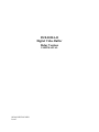
1
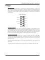
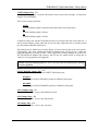
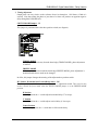
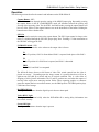
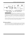
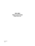
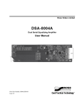
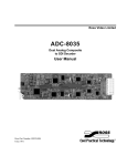
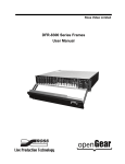
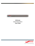
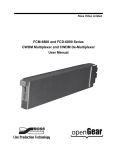
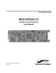
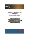
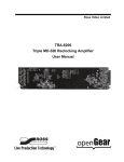
DVB-8020A-D Digital Video Buffer Delay Version USER MANUAL 8020A-D-DVB-03-MNL Issue 3 DVB-8020A-D • Digital Video Buffer Delay Version – User Manual • • • Ross Part Number: 8020A-D-DVB-03-MNL Document Issue: 3 Printing Date: March 15, 2000. Printed in Canada. The information contained in this guide is subject to change without notice or obligation. Copyright © 2000 Ross Video Limited. All rights reserved. Contents of this publication may not be reproduced in any form without the written permission of Ross Video Limited. Reproduction or reverse engineering of copyrighted software is prohibited. Notice The material in this guide is furnished for informational use only. It is subject to change without notice and should not be construed as commitment by Ross Video Limited. Ross Video Limited assumes no responsibility or liability for errors or inaccuracies that may appear in this manual. Trademarks • • • is a registered trademark of Ross Video Limited. and RossGear are registered trademarks of Ross ROSS Ross, ROSS, Video Limited. All other product names and any registered and unregistered trademarks mentioned in this guide are used for identification purposes only and remain the exclusive property of their respective owners. Company Address Ross Video Limited 8 John Street Iroquois, Ontario, K0E 1K0 Canada Ross Video Incorporated P.O. Box 880 Ogdensburg, New York USA 13669-0880 General Business Office: (+1) 613 • 652 • 4886 Fax: (+1) 613 • 652 • 4425 Customer Service: (+1) 613 • 652 • 4886 E-mail (Customer Support): [email protected] E-mail (General Information): [email protected] Website: http://www.rossvideo.com After hours emergency: (+1) 613 • 652 • 4886, ext. 333 DVB-8020A-D Digital Video Buffer - Delay Version Introduction The DVB-8020A-D is perfectly suited to solve system timing problems where the difference in delay is predictable between two paths. An example of this would be a situation where a sub-switcher needs to have clean switches between the output of a production switcher and some of the same input sources to equal the delay of the production switcher. Using the DVB-8020A-D to delay the input sources to equal the delay of the production switcher will effectively solve your timing problem. An added advantage of using the DVB-8020A-D instead of a frame synchronizer when you only need to delay a few lines, is that the delay will not be enough to create a visible lip-sync problem. Another feature of the DVB-8020A-D is an apparent negative delay that can be attained by setting the delay to just short of a full frame. This DA sized card will also freeze video from any CCIR 601 source, and makes a great companion to a production switcher. The freeze is triggered by a GPI or through a push button on the card. Freeze frames are saved instantly into RAM memory. Field 1, field 2, or a full frame of frozen video can be displayed. The DVB-8020A-D drives four serial digital outputs. Both 525 line and 625 line video formats are automatically supported. EDH, embedded audio, and other ancillary data are passed untouched. The DVB-8020A-D processes serial CCIR-601 signals with full 10 bit accuracy. The DVB-8020A-D can be remotely controlled by a GPI or an optional control panel. The DVB-8020A-D occupies one slot in the Ross DFR-8104 1RU and the DFR-8110 2RU digital rack frames. It is also fully compatible with the Leitch*6800 series digital rack frame. If you are looking for a product which provides full frame synchronization of CCIR-601 video, please refer to the DVB-8020A-S. It's no secret Ross products are tough. They are built to handle years of demanding, continuous use. The DVB-8020A-D is backed by a 5 year transferable warranty. Features Fully digital 10 bit signal processing and storage Automatic 525/625 line operation Card-edge horizontal and vertical timing delay adjustments Timing adjustments are automatically restored following a power loss Three vertical blanking output modes - 10 line, 20 line, or auto detect Frozen field output mode for flicker-free images with motion content Card-edge and/or GPI remote controlled operation Optional control panel Fault Reporting Capability Four serial digital outputs 6 modules fit into 2RU frame Also fits Leitch*6800 series frames * Leitch is a trademark of Leitch Technology Corporation 1-1 DVB-8020A-D Digital Video Buffer - Delay Version Installation 1) Cables SDI Input/Output Connect the input and output cables. The serial input is internally terminated in 75 ohms. The BNC connectors on the rear of the frame are marked for distribution amplifiers having eight outputs. However, the DVB-8020A-D has four serial digital outputs and the rest of the BNCs are unused (they are used with other variants of the DVB-8020). It is not necessary to terminate the unused outputs. Cable Connections Serial Out 2 Serial Out 4 Control Panel Not Used IN 2 1 4 3 6 5 8 7 Serial In Serial Out 1 Serial Out 3 Not Used GPI In GPI Input Connection The GPI input connection can be wired to a momentary push-button. For best operation, wire the push-button between the signal wire and the ground shielding of the coax cable. A 0V to 5V logic connection will also work assuming the controlling equipment is at the same ground potential. The GPI input is normally high and is negative edge triggered. The GPI input can also be tested by momentarily attaching a standard 75-ohm termination to the GPI In BNC. Control Panel Connection The control panel is supplied with 10 ft. (3 meters) of flexible cable with a female BNC connector. This should be extended with a conventional coax cable to the video frame and connected to the Control Panel BNC (output 6). Up to 300 ft. (90 meters) of any type of coax cable may be used. Secure the junction between cables to a firm surface near the desk using a large staple, tape or other means. A separate power source for the panel is not required as power is obtained via the coax cable. 1-2 DVB-8020A-D Digital Video Buffer - Delay Version 2) Jumper Plugs Set the jumper plug to meet system requirements. The selection of 525 line or 625 line video standards is automatic. MODE Jumper Plug - JP2 This jumper plug is positioned behind the three position switch. It allows you to choose from four modes of operation: GRAB mode Pressing the capture button will cause a new grab of the incoming video. Active video is not passed through the card — only frozen video. The F1/F2/FRM switch is active, EDH is re-calculated, and ancillary data is muted. PASS/FREEZE mode After power-up, incoming video is passed through the DVB-8020A-D untouched. Repeatedly pressing the capture button then alternates between freezing the output video and passing the input video untouched. When the output video is frozen, the F1/F2/FRM switch is active, EDH is re-calculated and ancillary data is muted. PASS mode Incoming video and ancillary data are passed through the DVB-8020A-D untouched. Both the capture button and the GPI input are disabled. The F1/F2/FRM switch has no affect. STILL mode Same as the PASS mode. 1-3 DVB-8020A-D Digital Video Buffer - Delay Version VI END Jumper Plug - JP5 This three position jumper is located at the bottom of the card near the card edge. It controls the length of vertical blanking. There are three jumper positions: AUTO Vertical blanking length is automatic and matches that of the input picture. 20 Vertical blanking length is 20 lines. 10 Vertical blanking length is 10 lines. It should be made clear that the DVB-8020A-D does not actually blank the vertical interval - it merely inserts blanking signal codes that are used by other equipment such as encoders which may later blank within that marked area. The blanking area is marked to prevent the display of vertical interval data in the active picture. Unfortunately, some older equipment depends on blanking being exactly 10 lines. Other new equipment depends on exactly 20 lines. Some equipment use other standards or doesn't care. The DVB-8020A-D handles both schemes and also has the added benefit of being able to "interface" new equipment to old equipment. NOTE: setting the blanking jumper to "10" or "20" may cause an "EDH missing" warning on some equipment. FAULT REPORT Jumper Plug - JP3 Use this jumper to enable or disable the SMPTE 269M fault report. ENABLE Put the jumper in the E (ENABLE) position to enable the fault report. DISABLE Put the jumper in the D (DISABLE) position to disable the fault report. NO I/P Jumper Plug - JP5 Not used on this model. Leave in the FREEZE position. GPI 1 Jumper Plug - JP8 Not used on this model. Leave in the GPI position. A B Jumper Plug - JP11 Not used on this model. Leave in the A position. 1-4 DVB-8020A-D Digital Video Buffer - Delay Version 3) Timing Adjustment Output phase can vary relative to the reference from 0 ns through to 1 full frame (1/30th of a second). Note that setting the phase to just short of a frame can produce an apparent negative delay through the DVB-8020A-D. SWITCH MODE Jumper - JP1 This jumper is positioned above the three position switch (see diagram). TIMING MODE If the jumper is moved away from the board edge (TIMING MODE), phase adjustment is enabled. FREEZE MODE If the jumper is moved towards the board edge (FREEZE MODE), phase adjustment is disabled and the freeze mode can be changed. In effect, this jumper changes the meaning of the adjacent three-position switch. H/V Switch - Horizontal and Vertical Delay Select - SW1 This three position switch determines the effect of the +/- adjustment switch. This switch is also used to control the freeze mode when the SWITCH MODE jumper is in the FREEZE MODE position. H Position In the H position the +/- switch adjusts horizontal delay (37 ns steps). V Position In the V position the +/- switch adjusts vertical delay (1 line steps). Center Position In the center position, the +/- switch has no effect on the delay. 1-5 DVB-8020A-D Digital Video Buffer - Delay Version Output timing is relative to the Serial In digital video input. There will always be a nominal delay through the card. The timing adjustments can add to that nominal delay up to just short of one frame. Setting the delay to just short of a frame can produce an apparent negative delay through the DVB-8020A-D. +/- Switch - Horizontal and Vertical Delay Adjust - SW2 This spring-loaded two position switch adjusts horizontal and vertical delay according to the setting of the H/V switch. "Accelerated ballistics" are applied to this switch for both fine and coarse control. When the switch is pressed, the minimum possible delay change will take place followed by a short pause. Additional changes will then be added at an accelerating rate until a maximum rate of change is applied. As a result, "tapping" the switch in H mode will add one clock of delay. Tapping the switch in V mode will add one line of delay. In the H mode, delay is added or removed in single clock steps (+/- 37 ns) and will eventually cross into the next line. Delay changes may continue until the minimum or maximum delay of the DVB-8020A-D is attained. At that point, no further delay change will occur. In the V mode, delay is added or removed in single line steps (+/- 64 us). Delay changes may continue until the minimum or maximum delay attainable on the DVB-8020A-D is reached without affecting the horizontal phase. At the point of minimum vertical delay, tapping the '-' switch will set the horizontal phase to zero. Unless the phase change direction is changed, no further phase changes will occur. 1-6 DVB-8020A-D Digital Video Buffer - Delay Version Operation The following sections describe the controls and indicators on the DVB-8020A-D: Capture Button - SW3 What this button does depends upon the setting of the MODE jumper plug. Repeatedly pressing the capture button in the PF (PASS/FREEZE) mode will alternate between the passing and freezing of the incoming video. For the STILL and PASS mode, pressing the capture button will have no effect. Effects of the capture button occur on the downstroke of the button. Holding the button down will have further effect. GPI 1 In This input works exactly the same as the capture button. The GPI 1 input control is always active unless it is disabled through the GPI 1/RX jumper plug. Note: Touching a 75-ohm termination to the GPI BNC will trigger the GPI. F1/FRM/F2 Switch - SW1 This three-position switch is active whenever the output video is frozen. F1 In the F1 position, field 2 is discarded and field 1 is repeated in the place of the field 2. F2 In the F2 position it is field 2 that is repeated, and field 1 is discarded. FRM Both field 1 and field 2 are outputted. The 8020A-D always freezes as full frame of video. This switch controls how the video is played out storage. Depending upon the image content it is possible that there will be an apparent one line shift up or down and loss of vertical resolution. This is a side effect of dropping a field of picture information. The F1 and F2 positions are used when the capture of moving video might cause annoying motion flicker. When capturing graphics or character generator outputs that have no motion content, use the FRM position. The FRM position plays a full frame out of storage. Red ERROR Light This light will illuminate when the digital input is absent or interrupted. Yellow BUSY Light This light will illuminate briefly when the DVB-8020A-D is storing delay information into non-volatile memory. Green OK Light This light will illuminate when the input is present. 1-7 DVB-8020A-D Digital Video Buffer - Delay Version Fault Reporting Capability - JP3 Fault reporting in the SMPTE 269M standard has been implemented in this issue. This is a simple system which can indicate that one or more of the modules in the rack frame has encountered a fault or abnormal condition. Each rack frame has a "telco" connector which can be connected to an external "contact closure" type of alarm system. A customer-devised system of lights can be used to trace a fault to a rack cabinet, rack frame, then a particular card. For more information on designing such a system, refer to SMPTE document ANSI/SMPTE 269M 1994. If the FAULT REPORT jumper is enabled (the 'E' position), the output will be a steady low signal if there is no power in the module. The output will pulse at a field rate if the input signal is very low or absent. In all other situations, the output is open (high impedance). Maintenance and Repair Routine Maintenance is not required. If the module does not appear to be working properly, return it to Ross Video Ltd. for repair. All Ross digital distribution products are covered by a generous 5-year warranty and will be repaired without charge for materials or labor in this period. See "Ross Gear Terminal Equipment - Warranty and Repair Policy" in this manual. 1-8 DVB-8020A-D Digital Video Buffer - Delay Version Specifications SMPTE Signal Standards 270 Mb/s, 525/625 Component Digital Accommodated (SMPTE 259M-C) Serial Video Input Connector: BNC Impedance: 75 ohm, terminating Equalization: 300 m Return Loss: >21 dB @ 270 MHz Serial Video Outputs Number of Outputs: 4 Connector: BNC Impedance: 75 Ohm Return Loss: >17 dB @ 270 MHz Signal Level: 800 mV ± 10% DC Offset: ± 30 mV Rise & Fall Time: approx. 800 ps (20 - 80)% Overshoot: < 8% Jitter added to Digital Ref.: < 220 ps Delay Range minimum: 19 clocks, 9.5 pixels, or 703 ns maximum: 1 frame + 9.5 pixels (including max. fine phase) Phasing Range 0 ns - 1 frame (infinite) Signal Quantization 10 bit throughout Power Consumption 8W 1-9 DVB-8020A-D Digital Video Buffer - Delay Version Ordering Information DVB-8020A-D DFR-8104A DFR-8110A PS-8102 EXT-8100 310-008 Digital Video Buffer, Delay Version Digital Products Frame, 1RU, holds 4 modules Digital Products Frame, 2RU, holds 6 modules Universal Power Supply (85-250 Volts) Extender Board BNC Termination 0.1% precision, 75 ohm Note: All Ross Video Limited terminal equipment frames include one power supply. A redundant power supply may be installed in all two rack unit frames if required. One User Manual is supplied with each frame. 1-10 RossGear Terminal Equipment • Warranty and Repair Policy This RossGear Terminal Equipment product is warranted to be free of any defect with respect to performance, quality, reliability and workmanship for a period of FIVE (5) years from the date of shipment from our factory. In the event that your RossGear product proves to be defective in any way during this warranty period, we will gladly repair or replace this piece of equipment with a unit of equal or superior performance characteristics. Should you find that this RossGear product has failed after your warranty period has expired, we will repair your defective piece of equipment for as long as suitable replacement components are available. You, the owner, will bear any labor and/or component costs incurred in the repair or refurbishment of said equipment, beyond the FIVE (5) year warranty period. Should your RossGear product be of our Digital Terminal Equipment product line, a power supply, or product with surface mount devices, and it proves to be defective, we would ask that an authorized Ross Video Limited factory representative repair the product. Any attempt to repair this product by anyone other than an authorized Ross Video Limited factory representative, will void your warranty. If this is a manual for a RossGear product of our Digital Terminal Equipment product line, a power supply, or piece of equipment that carries surface mount devices, you will find it provides all pertinent information for the safe installation and operation of your RossGear product. If this is a manual for a RossGear product from our Analog Terminal Equipment product line, you will find it provides all pertinent information for the safe installation and operation of your RossGear product. Included in this manual (if this product does not carry any surface mount devices) you will also find schematics, bills of materials and layout drawings. These are provided for your convenience, should you find it necessary to perform discretionary field repair or modifications to your RossGear product. Ross Video Limited reserves the right to assess any modifications or repairs made by you and decide whether they fall within warranty limitations, should you decide to return your RossGear product for repair. In no event shall Ross Video Limited be liable for direct, indirect, special, incidental, or consequential damages (including loss of profits) incurred by the use of this product. Implied warranties are expressly limited to the duration of this warranty. IN CASE OF PROBLEMS: Should any problem arise with your RossGear Terminal Equipment Product, please contact our Customer Service Department at 613-652-4886, 24 hours a day, 7 days a week. A Return Material Authorization number (RMA) will be issued to you, as well as specific shipping instructions, should you wish our factory to repair your RossGear product. A temporary replacement, if required, will be made available for a nominal charge. Any shipping costs incurred, will be the responsibility of you, the customer. All products shipped to you from Ross Video Limited, will be shipped collect. RossGear Terminal Equipment product advice is available, without charge, for the life of this equipment.