1
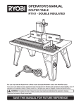
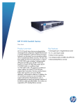
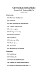
PART II
ABOVETABLE
X-RAY SOURCE
RADIOGRAPHIC
SYSTEMS
FORM FDA 2784
REPRINTED
APRIL 2000
ROUTINE COMPLIANCE TESTING
ABOVETABLE X-RAY SOURCE
RADIOGRAPHIC SYSTEMS
(Test Procedure ARA - Use Form FD2784)
1.0 GENERAL GUIDANCE
1.1
This procedure applies to the testing of any stationary x-ray system employing an
abovetable source for radiography, a conventional undertable cassette tray, either
manual or both manual and automatic control of radiographic technique factors, and
a variable aperture beam limiting device. The procedure applies to systems
operating at fixed as well as variable SIDs that are equipped with either manual or
automatic positive beam limiting (PBL) devices or manual non-PBL devices.
1.2
When a step or entire section of the procedure is skipped, enter an asterisk in the
first data item of that section, explain on a "continuation sheet" why this was skipped,
and continue on with the next appropriate section.
NOTE: If multiple indicators are provided for a single parameter (e.g.,
perpendicularity, centering, kVp, and so forth) but the indicators do not agree with one
another, choose the indicator (1) associated with a certified component and (2) most
commonly used. Note on a "continuation sheet" that these indicators do not agree, and
estimate the amount of discrepancy.
2.0 PRETEST CHECKLIST
2.1
Turn on the main power to the x-ray system. Set up the system so that it will
operate in the radiographic mode to the undertable cassette tray and bucky.
2.2
Connect the 6-cm3 chamber to the electrometer. Set the x-ray monitor mode
selector switch to EXPOSURE RATE and the function selector switch to MEASURE.
Allow the electronics 10 seconds to stabilize. After 10 seconds, the exposure rate
should be less than 4 mR/min. If it is not, the instrument may be defective and you
should contact CDRH for guidance.
2.3
If not already completed, complete the general information test record.
2.4
Record the five digits, which appear preprinted on the general information test
record, and a unique letter designator, in the appropriate block for each page of the
abovetable radiographic test record. Thus, test records for a combination
abovetable radiographic undertable fluoroscopic system would be identified as
follows: "GI12345" - general information; "AR12345A" - abovetable radiographic;
"UF12345B" - undertable fluoroscopic. (Note that the unique letter designation
changes when testing a different X-ray source).
PART II
AR-1
04/1/2000
2.5
Verify that the assembler's report, (FDA 2579) is correctly prepared. If it is not, write
in the correct information above the incorrect information.
2.6
Record the code for the appropriate "Test Procedure" at item 1.
2.7
Record the manufacturer's name and model number and serial number as listed on
the identification label for the beam-limiting device in items 2 and 3.
2.8
Record the manufacturer's name, model number, and serial number as listed on the
identification label for the x-ray table in items 4 and 5.
2.9
Check the certification status of each component to determine if the components are
certified without a variance (C), certified with a variance (V), not certified (N), or not
present in the system (X). DO NOT include other components such as wall
cassettes or spot film devices, which are not used for abovetable radiography.
Record this data at item 6.
3.0 INITIAL SETUP
3.1
Turn on the light localizer to assure that it is operable. If it is not, explain on a
"continuation sheet" and skip sections 8.0, 9.0, 10.0, 11.0 and 12.0.
3.2
Are means provided to indicate when the beam axis is perpendicular to the plane of
the image receptor? Record at item 7. If "Yes," use the indicator(s) to align the
beam axis perpendicular to the plane of the image receptor. If "No," use any
available method to align the beam axis; e.g., visual inspection.
3.3
Are means provided to center the diagnostic source assembly over the image
receptor? This requirement can be met by a Bucky light, table markings, cassette
tray center markers, a light localizer, tubestand detent, or other similar devices.
Record at item 8.
3.4
Place either a plastic cassette containing a sheet of direct-print paper or a loaded
film cassette into the bucky tray and center the diagnostic source assembly over the
image receptor.
3.5
Set up the test stand and equipment as follows (see figure on test record):
a)
Place the test stand on the table approximately centered beneath the source
assembly with the long axis of the base parallel to the long axis of the table.
b)
Attach the spacer assembly to the top of the test stand, positioned out of the
beam.
c)
Position the 6-cm3 chamber in the lower mounting hole of the test stand and
secure with the retaining ring.
d)
Insert the slide assembly, grid side up, in slot 6 of the test stand.
PART II
AR-2
04/1/2000
e)
Insert a plastic cassette containing a sheet of direct print paper into the slide
assembly.
3.6
Turn on the light localizer and center the test stand beneath the source assembly by
centering the light field on the slide assembly grid. A piece of white paper in the slide
assembly makes visualization of the light field easier during setup. Remove it when
the setup is complete.
3.7
Lower the source assembly to the minimum SID position or until the face of the
beam-limiting device comes down close to or in contact with the spacer assembly.
NOTE: In order to reduce the error in the SID measurement, adjust the source
assembly such that the SID indicator is on a division mark. It is not necessary for
the BLD to actually be in contact with the spacer assembly. Lock the vertical
movements of the source assembly and tabletop.
3.8
Adjust the beam limiting device so that the light field is approximately 4" x 6" at the
slide assembly with the longer dimension parallel to the long dimension of the table.
Using a piece of white paper at the top of the test stand, check all edges of the light
field against those of the opening in the top of the test stand to make sure that the
light field is not shielded by the stand and that it passes through the opening in the
top of the stand.
3.9
Define the edges of the light field on the slide assembly grid by placing the metal
marker strips so that the outside edge of the marker is along the inside edge of the
light field and one end of the marker is along the central line of the grid. Again, avoid
disturbing the slide assembly or the test stand.
NOTE: One method of checking if the outer edge of the metal
marker is on the edge of the light field is as follows:
a)
Set a sheet of white paper alongside the metal marker.
b) Note the edge of the light field on the paper. Move the metal marker so that the
outer edge is in line with the image of the light field on the white paper.
c)
Set a corner of the white paper on the metal marker so that approximately 1/4"
of the marker extends on each side of the triangle formed by the corner of the
paper. The bright outline of the light field should be co-linear with the edge of the
metal marker. If it is not, adjust accordingly.
3.10
Quickly recheck the alignment of the source assembly, test stand, and image
receptor. Make any necessary adjustments. If adjustments are made, check the
alignment of the marker with the light field as noted in 3.9.
3.11
Record the indicated SID at item 9 of the test record. If the unit operates at a fixed
SID that is not indicated, look in the user's manual.
3.12
Place a total of 4.5 mm of aluminum in slot 1 of the test stand.
PART II
AR-3
04/1/2000
CAUTION: Consult the system's duty cycle information and anode cooling curves to
ensure that the following series of exposures will not exceed the manufacturer's
anode heat loading specifications. If the proper cooling time between exposures
cannot be determined, use the following guidance:
3.13
a)
Rotating anode tubes: Wait 60 seconds after every accumulated 5,000 heat
units loading of the anode.
b)
Stationary anode tubes: Wait 30 seconds between exposures of less than 900
heat units and 60 seconds between exposures of 900 to 1800 heat units.
If a loaded film cassette is used at step 3.4, set the x-ray control to 60 kVp and 4
mAs (or as close to these technique factors as possible). Make an exposure and
have the x-ray technician process the film for you. If a readable image is not
obtained at these technique factors, adjust the technique factors appropriately and
repeat the exposure. Set the developed film aside for later determination of the
centers alignment and continue with the next step.
4.0 BEAM QUALITY
4.1
If both "Manual" and "Automatic" controls are provided for exposure termination,
select the "Manual" mode of operation.
4.2
Select a commonly used technique in the above 70 kVp range. Record the selected
kVp at item 10.
4.3
(a) Choose independent values of tube current and exposure time commonly used
and record at item 11 and 12. Leave item 13 blank.
(b) If only mAs is selectable, choose a value commonly used and record at item 13.
Leave items 11 and 12 blank.
4.4
If the capability is provided for adjustment of the filtration present in the useful beam,
adjust for minimum filtration that will allow an exposure in the above 70 kVp range.
(Many systems have an Exposure Hold light to indicate that exposure cannot be
made without the filter present in the beam. If an exposure is possible with the
filtration removed and the Exposure Hold light lit, continue with sections 4.0 through
6.0 in this condition of operation.)
4.5
Determine whether the system is single-phase or three-phase, using one or more of
the following methods:
(a) Consult the user information provided by the high-voltage generator or x-ray
control manufacturer.
(b) Check the identification plate of the high-voltage generator. Many times the
manufacturer lists the phase of the system along with other electrical
characteristics on this label.
PART II
AR-4
04/1/2000
(c) Observe the time settings on the control panel. Single-phase timer settings are
usually expressed as common fraction multiples of 1/120 second, while threephase systems usually have timer settings expressed as decimal fractions.
Is the system single-phase or three-phase? If the system is single-phase, set the
"Pulse-Fraction Threshold" on the MDH to 0.2, and record at item 14. If the system
is three-phase, set it to 0.5, and record at item 14.
4.6
Set the x-ray monitor mode selector switch to PULSE EXPOSURE and the function
selector to MEASURE.
4.7
The x-ray monitor display should read -0.00. If any other display is present, reset the
instrument by switching the function selector to HOLD and then back to MEASURE.
4.8
Are the technique factors visible at the operator's position? Record at item 15.
4.9
If multiple tubeheads are controlled by a single exposure switch, is there an
indication of which tubehead has been selected, both at the control panel and at the
selected tubehead? Record at item 16.
4.10
Is there a warning label as prescribed in 21 CFR 1020.30(j) present on the control
panel containing the main power switch? Record at item 17.
4.11
Make an exposure and record the resulting reading at item 18 of the test record.
4.12
Without changing technique factors, remove aluminum to obtain totals of 3.5, 2.5
and 1.5 mm and repeat the procedure of step 4.11 for each total. Record the
exposure readings at items 19 through 21.
4.13
Remove all of the aluminum absorbers from Slot 1.
4.14
Did the exposures terminate after one of the following: a preset time interval, a
preset mAs, or a preset number of pulses? Record at item 22.
NOTE: The intent of this question is to identify conditions that pose an
imminent hazard; e.g., a system which upon activation of exposure button
causes not one but repeated exposures to occur or termination of the
exposure occurs only upon release of the exposure switch.
5.0 REPRODUCIBILITY AND LINEARITY
5.1
Reset the x-ray monitor so that the display reads -0.00. Without changing the
technique factors make an exposure. Do not record the resultant reading.
5.2
Without changing technique factors or the x-ray monitor settings, make an additional
exposure. The reading will not have a minus sign present. Record this reading of
exposure at item 23. Switch the mode selector to PULSE DURATION and record
this time reading at item 24. Switch the mode selector back to PULSE EXPOSURE.
PART II
AR-5
04/1/2000
5.3
Repeat step 5.2 for three additional exposures, with the exposure readings being
recorded at items 25, 27, and 29 and the time readings being recorded at items 26,
28, and 30. Do not reset the x-ray monitor between exposures. All variable controls
for technique factors shall be adjusted to alternate settings and reset to the test
setting after each measurement.
NOTE: The varying of technique factors to alternate settings and then back to
the test setting is only applicable to equipment manufactured after September 5,
1978.
5.4
Should the above exposure and/or timer readings appear suspect (i.e., any two
readings differ by 10 percent or more of the greater value) make an additional six
exposures, for a total of ten data points. Record at items 31 through 42.
5.5
If the x-ray control is manufactured before May 1994, follow the guidance of
paragraph a. under each step for this test section, otherwise use paragraph b.
5.6
5.7
a.
If the unit under test either does not allow specific selection of tube current, or, if
only mAs is selectable, then omit procedural steps 5.6 through 5.9, enter an
asterisk in the first column of item 43 on the test record, and state on a
"continuation sheet" that the mA is fixed, or that mAs is selected.
b.
Enter a new mAs product (not to exceed twice the first mAs product) at item 43
on the test record. If a new mAs product cannot be obtained, then enter an
asterisk in the first column of item 43 on the test record and state on the
"continuation sheet" that the mAs product is fixed.
a.
If tube current selection is in fixed steps, select an adjacent tube current step
and record the indicated value at item 43.
b.
If tube current or mAs is in fixed steps, select an adjacent setting and record the
mAs product at item 43.
a.
If tube current selection is continuous (i.e., not in discrete steps), select a
second tube current not differing from the first by more than a factor of 2, and
record its value at item 43.
b.
If the tube current or mAs is continuous (i.e. not in discrete steps), select a
second setting not differing from the first by more than a factor of 2, and record
the mAs product at item 43.
5.8
The change in tube current may cause a change in tube potential. If manual
compensation is available, readjust the tube potential to its original value, and
continue with step 5.9. However if the kVp cannot be compensated back to its
original setting, enter an asterisk in the first column of item 44, skip procedural step
5.9, and state in the Remarks that the kVp could not be compensated.
5.9
While varying technique factors between each measurement as in step 5.3, make
four exposures at the selected technique factors. Record the exposure readings at
items 44, 45, 46, and 47.
PART II
AR-6
04/1/2000
5.10
Sum the exposures entered on the test record. If the sum is 1 R or greater, the
direct-print paper in the slide assembly should provide a satisfactory image. Make
additional exposures, if required, to obtain at least 1 R to the ion chamber.
5.11
Remove the cassette from the slide assembly and develop the direct-print paper by
exposure to fluorescent light. (Refer to page LINA-1 for proper development
techniques.) If a readable image has not been obtained, a new cassette with fresh
direct-print paper should be inserted and exposed after rechecking light field
alignment with the metal markers on the slide assembly.
6.0 ADDITIONAL EXPOSURES TO THE UNDERTABLE CASSETTE
IMPORTANT!
Should you have chosen to use direct print paper in the cassette tray (step 3.4),
a total exposure of 4.0 to 7.0 R to the ion-chamber is necessary to provide a
readable image on the direct-print paper. If the total exposure to the ion
chamber (step 5.10) is greater than 4 R, skip to step 6.2. However, if the total
exposure to the ion chamber is less than 4 R, perform 6.1.
6.1
Make additional exposures as required to obtain at least 4 R to the ion chamber.
Check the anode cooling curves to ensure that the rated anode limits are not
exceeded.
6.2
Remove the cassette from the cassette tray. Develop the direct-print paper by
exposure to fluorescent light.
7.0 SID DETERMINATION
7.1
With the test stand still in position beneath the source assembly, measure the
distance from the focal spot to the tabletop to the nearest millimeter. Unless the
focal spot location is marked on the tube housing, estimate the focal-spot or source
location as being in a plane halfway down the housing end cap from the axial
centerline of the tube housing assembly. In other words, the focal spot is 1/4 the
way up the housing end cap from the x-ray beam exit side. Using the test kit
measuring tape, measure the distance from the source to the tabletop. Record the
measurement at item 48.
7.2
Place a film cassette into the cassette tray.
7.3
Partially insert the cassette tray.
7.4
Measure to the nearest millimeter the distance from the top of the cassette to the
base of the test stand and record at item 49.
NOTE: If the system is equipped with a concave tabletop, measure both the vertical
distance from the top of the cassette to any reference point on the test
PART II
AR-7
04/1/2000
stand, and the distance from that reference point to the base of the test
stand. Subtract the second measurement from the first, and record the
difference at item 49. (See Figure 1.) Some systems are equipped with a
cassette tray that raises vertically after it is inserted into the table. In this
case, before the cassette tray is inserted, measure the vertical distance
from the top of the cassette to a reference point on the cassette tray that will
remain visible after the tray has raised into position. Insert the tray and
activate the raising mechanism. Then measure the vertical distance from
the reference point to the base of the test stand, subtract the first
measurement from the second, and record the difference at item 49. (See
Figure 2.)
8.0 PBL X-RAY FIELD/UTIR SIZE COMPARISON
8.1
Remove the test stand and other equipment from beneath the tubehead.
8.2
Select two commonly used sizes of cassettes. Record the film dimensions of the
first cassette at items 50 and 51. In all cases, dimensions of image receptors or
light field measurements will be characterized as "along the table" for a direction
along the long dimension of the table and "across the table" for a direction
perpendicular to the long dimension of the tabletop. If only one cassette size is
available, it may be rotated to swap length and width dimensions (provided it is not
the same dimension on each side).
8.3
Place the first cassette into the cassette tray and insert the cassette tray. Select
two SIDs at which the PBL sensors operate (preferably one short and one long SID).
8.4
Set the source assembly at the first SID and lock into place. Make an exposure to
ensure that the system operates at this SID. If an exposure is not possible, move to
a SID at which an exposure may be made. Record this indicated SID at item 52.
8.5
Record at item 53 the type of PBL with which the system is equipped. Either the
PBL system automatically adjusts the x-ray field when the cassette tray is inserted;
or the PBL system prevents production of x-rays until manual adjustments are
made; or no PBL system is present. It may be necessary to consult the user's
information to determine at which SIDs PBL is intended. If the beam limiting device
is not a PBL type, then record 'C' at item 53 and record an '*' at item 54, then skip
procedure steps 8.6 through 9.4.
8.6
If the system is equipped with PBL, determine if the PBL is functioning as intended.
a)
If an automatic PBL, does the unit automatically adjust field size?
NOTE: Since PBL devices by definition must be positive beam limiting, the following
has been useful in testing the PBL operation.
i. Partially withdraw the cassette tray, putting the system into "manual" mode.
PART II
AR-8
04/1/2000
C = A – B = DISTANCE FROM TOP OF FILM CASSETTE
TO BASE OF TEST STAND .
RECORD VALUE OF C AT ITEM 49
.
FIGURE 1: HOW TO DETERMINE DISTANCE FROM TOP
OF CASSETTE TO BASE OF TEST STAND FOR
CONCAVELY CURVED TABLE TOP.
PART II
AR-9
04/1/2000
C = B-A = DISTANCE FROM TOP OF FILM CASSETTE
TO BASE OF TEST STAND .
RECORD VALUE OF C AT ITEM 49
REFERENCE POINT IS
BASE OF CASSETTE TRAY,
WHICH REMAINS VISIBLE
EVEN AFTER TRAY IS
RAISED
FIGURE 2:
PART II
HOW TO DETERMINE DISTANCE FROM TOP
OF CASSETTE TO BASE OF TEST STAND FOR
RAISEABLE CASSETTE TRAY.
AR-10
04/1/2000
ii.
Manually open the collimator blades fully.
iii.
Turn on the light localizer.
iv.
Reinsert the cassette tray.
v.
Watch the image of the light field on the tabletop to see if the light field
adjusts down.
b)
If a "manual PBL," does it prevent the production of x-rays until manual
adjustments are made?
Record at item 54. If the PBL is not functioning according to its intended design, skip
over this section and section 9.0 and explain on a "continuation sheet."
8.7
Turn on the light localizer, measure to the nearest millimeter the dimensions of the
light field at the tabletop. Record the light field dimensions at items 55 and 56.
8.8
Set the source assembly to the second SID and lock into place. Repeat the
procedure of steps 8.4 and 8.7. Record the indicated SID at item 57 and light field
dimensions at items 58 and 59.
8.9
Remove the first cassette and insert the second.
8.10
Record the film dimensions of the second cassette at items 60 and 61.
8.11
Check the PBL sizing at two SIDs as detailed in 8.3, 8.4, 8.7, and 8.8, recording the
data in the appropriate spaces of items 62 through 67.
9.0 PBL OPERATIONS
9.1
Turn on the light localizer and close the beam-limiting device to the smallest field
possible. Is it possible to manually adjust the x-ray field size to a size smaller than
the image receptor? Record at item 68.
With the x-ray field size adjusted to a size smaller than the image receptor, pull out
the cassette tray, change the cassette to one of a different size (or rotate the same
one 90°), and reinsert it. Does the beam-limiting device return to positive beam
limitation? Record at item 69.
9.3
If possible, move the source assembly to an SID greater than 36" where the PBL
system is not intended to operate. Select low-range values of tube potential and
tube current and an exposure time of 0.5 second or longer.
9.4
Attempt to make an exposure. Is x-ray production prevented at SIDs where
operation is not intended? Record at item 70.
PART II
AR-11
04/1/2000
10.0 ACTUAL VERSUS INDICATED FIELD SIZE
10.1
Does the beam-limiting device numerically indicate the field size at an SID at which
the diagnostic source assembly can be set? Record at item 71,
10.2
Remove the film cassette. Set the diagnostic source assembly to the lowest SID for
which the field size dimensions in the plane of the undertable image receptor (UTIR)
are given on the BLD, and lock into position. Record the SID at item 72.
NOTE: If the diagnostic source assembly cannot be set to an SID for which
field size dimensions are given on the BLD, set the SID as close as possible to one
provided on the BLD.
10.3
Manually adjust the beam-limiting device for an indicated field size; e.g., 8 x 10
inches. Record the indicated field size at items 73 and 74.
10.4
Turn on the light localizer and measure to the nearest millimeter the dimensions of
the light field at the surface of the table. Record the dimensions at item 75 and 76.
11.0 ILLUMINANCE OF LIGHT LOCALIZER
11.1
If the SID is variable, set the diagnostic source assembly to a source to tabletop
distance of 42.5 inches (108 cm) or the maximum SID whichever is less. NOTE:
the 42.5 inches source to table top places the light sensitive surface of the digiphot
100 cm from the source. If a light meter other than the digiphot is used, be sure the
light sensitive surface is 100 cm from the source. Open the beam-limiting device to
an approximate field size of 10" x 10".
11.2
Set the photometer on the tabletop. (Refer to page PHOTO-1 for proper use of the
photometer.) Turn on the light localizer. At or near the center of one quadrant of the
light field, determine the illuminance by subtracting the ambient light level from the
corresponding light level when the light localizer is engaged. Do not move the
photometer between measurements. Record this illuminance at item 77.
NOTE: Do not apply the correction factor provided on the photometer to any of
the measurements. The recorded illuminance values must be uncorrected.
11.3
Repeat the measurements at or near the center of the other three quadrants of the
light field and record at items 78, 79, and 80.
12.0 X-RAY FIELD/LIGHT ALIGNMENT AND SIZE COMPARISON
12.1
Take the direct-print paper that had been in the slide assembly and was developed in
section 5.11.
12.2
Reconstruct the outline of the x-ray field using a straight edge and pencil or pen.
(see figure 3)
12.3
Reconstruct the image of the metal markers to their actual size (usually 0.5" x 1.5").
PART II
AR-12
04/1/2000
12.4
Measure the dimensions of the x-ray field image on the direct-print paper, to the
nearest millimeter. Record the x-ray field dimensions at items 81 and 82.
12.5
Measure the light field dimensions by measuring the distance from the outside edges
of the image of the marker strips which define the edge of the light field in each
direction. Record the light field dimensions at items 83 and 84.
12.6
Measure the distance from the outside edges of the marker strips and the outline of
the x-ray field in the direction along the table. Sum the two distances for the total
misalignment along the table. Record at item 85.
12.7
Determine the total misalignment across the table the same way as the total
misalignment along the table in step 12.6. Record at item 86.
13.0 X-RAY FIELD/UTIR CENTER COMPARISON
13.1
Depending upon the option chosen, refer to either the film that was processed by the
x-ray technician or to the direct-print paper from the cassette tray.
13.2
With a ruler and a pen or pencil, trace the perimeter of the x-ray field image. Draw
diagonals from opposite corners of the x-ray field to define the center of the field.
Likewise, draw diagonals from opposite corners of the film to define the center of the
film.
13.3
Measure to the nearest millimeter the misalignment between the center of the x-ray
field and the center of the film. Record at item 87.
PART II
AR-13
04/1/2000
Reconstructed image
of metal strips
L2
Dashed line
coincides with outer
edges of the four
metal strips and is
the perimeter of the
light field
W2
W1 = 0
In this
example
Along Table Misalignment = L1 + L2
Across Table Misalignment = W 1 + W 2
L1
Edge of x-ray field
Edge of direct –print paper
Figure 3
PART II
AR-14
04/1/2000