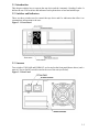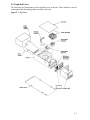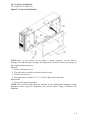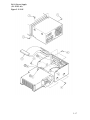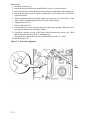
1
TM
TKZ60 Service Manual
Order Number: EK-A0662-SM.001
Digital Equipment Corporation
The information in this document is subject to change without notice and should not be
construed as a commitment by Digital Equipment Corporation.
Digital Equipment Corporation assumes no responsibility for any errors that may appear in
this document. No responsibility is assumed for the use or reliability of software on
equipment that is not supplied by Digital Equipment Corporation or its affiliated companies.
Restricted rights: Use, duplication, or disclosure by the U.S. Government is subject to
restrictions as set forth in subparagraph (c) (1) (ii) of the Rights of Technical Data and
Computer Software clause at DFARS 252.227-7013.
The Digital logo, OpenVMS, VAX, AXP, ULTRIX and DECwrite are all trademarks of the
Digital Equipment Corporation
All third-party trademarks are acknowledged as the proprietary property of their respective
owners.
Copyright © 1993 Digital Equipment Corporation. All rights reserved
This document was prepared, printed and published by The Digital Equipment Corporation,
using DECwrite V2.0
ii
Federal Communications Commission (FCC) Notice
This equipment generates, uses, and may emit radio frequency energy. The equipment has
been type tested and found to comply with the limits for a Class A digital device pursuant
to Part 15 of FCC rules, which are designed to provide protection against such radio
frequency interference.
Any changes or modifications made to this equipment may void the user’s authority to
operate this equipment.
Operation of this equipment in a residential area may cause interference in which case the
user at his own expense will be required to take whatever measures may be required to
correct the interference.
Acoustics - Preliminary declared values per ISO 9296 and ISO 7779:
Sound Power Level Sound Pressure Level
LWAd, B
LpAm, dBA
(bystander positions)
Product
Idle
Operate
Idle
Operate
TKZ60 (tabletop)
5.8
5.8
46
46
TKZ60 (rack-mount) 5.8
5.8
39
40
[Current values for specific configurations are available from Digital representatives.
1 B = 10 dBA.]
iii
..
Fur Bundesrepublik Deutschland
For Federal Republic of Germany
Pour la Republique federale d’Allemagne
VDE Statement
BESCHEINIGUNG DES HERSTELLERS/IMPORTEURS
..
..
Dieses gerat ist in Ubereinstimmung mit den Bestimmungen der BMPT Vfg.243/1991 und
Vfg.46/1992 in Verbindung mit EN55022:1987 (DIN VDE 0878-3:11.89), oder
..
..
Vfg.1046/1984 mit Vfg.483/1986, funkenstort. es tragt als Nachweis der
..
..
EMV-Konformitat entweder eine Konformitatskennzeichnung oder das freiwillige
VDE-Funkschutzzeichen.
..
..
Der vorschriftsmaβige betreib mancher Gerate (z.B Meβsender) kann
..
allerdingsgewissen Einschrankungen untrliegen. Beachten Sie deshalb die
..
unten aufgefuhrten Hinweise.
..
..
Fur Gerate die nicht mit dem VDE-Funkschutzzeichen versehen sind
..
wurde dem Bundesamt fur Zulassungen in der Telekommunikation (BZT)
das Inverkehrbringen diesses Gerates angezeigt und die Berechtigung zur
..
..
..
Uberprufung der Serie auf Einhaltung der Bestimmungen eingeraumt.
Betreiberhinweis
Wir sind verpflichet, Sie auf folgende Fakten hinzuweisen (BMPT..
Amtsblattverfugung
243/91 bzw. 1046/84 δ2, Abschnitt 5):
..
..
..
..
Dieses Gerat wurde funktechnisch sorgfaltig entstort und gepruft. Wird dieses
..
..
Gerat innerhalb einer Anlage zusammen mit anderen Geraten betrieben, muβ bei
Inannspruchnahme der "Allgemeinen Betriebsgenehmigung" nach
BMPT-AmtsblVfg 243/91 bzw. 1046/84 die gesamte Anlage den unter δ2,
Abschnitt 1, genannten Voraussetzungen entsprechen.
Externe Datenkabel
..
Solite ein Austausch der von Digital spezifizierten Datenkabel notig werden,
..
..
muβ der Betreiber fur eine einwandfreie Funkentstorung sicherstellen, daβ
..
Austauschkabel im Aufbau und Abschirmqualitat dem Digital Originalkabel
entsprechen.
Schallemissionswerte - Vorläufige Werteangaben nach ISO 9296 und
ISO 7779/DIN EN27779:
Schalleistungspegel Schalldruckpegel
LWAd, B
LpAm, dBA
(Zuschauerpositionen)
Gerät
Leerlauf Betrieb
Leerlauf Betrieb
TKZ60 (tabletop)
5,8
5,8
46
46
TKZ60 (rack-mount) 5,8
5,8
39
40
[Aktuelle Werte für spezielle Ausrüstungsstufen sind über die Digital Equipment
Vertretungen erhältlich. 1 B = 10 dBA.]
iv
Contents
Preface .................................................................................................................................xi
Introduction.................................................................................................................. xiii
Product History ............................................................................................................ xiii
Manual Structure ......................................................................................................... xiii
Intended Audience ....................................................................................................... xiii
Related Documents ...................................................................................................... xiii
1 - Product Overview ............................................................................................... 1-1
1.1 Physical Description ............................................................................................ 1-3
1.2 Functional Description ........................................................................................ 1-4
1.2.1 Interface ................................................................................................ 1-4
1.2.2 Electronics ............................................................................................ 1-4
1.2.3 Electromechanics.................................................................................. 1-4
2 - Hardware Configurations ................................................................................ 2-1
2.1 Introduction ......................................................................................................... 2-3
2.2 Fully Supported Configurations .......................................................................... 2-3
2.3 Custom Quoted Configurations ........................................................................... 2-3
2.4 Options & Accessories ........................................................................................ 2-3
3 - Operating Procedures ....................................................................................... 3-1
3.1 Introduction ......................................................................................................... 3-3
3.2 Switches and Indicators ....................................................................................... 3-3
3.3 Switches............................................................................................................... 3-3
3.4 Switch Functions ................................................................................................. 3-4
3.4.1 UNLOAD switch .................................................................................. 3-4
3.4.2 FORMAT switch .................................................................................. 3-4
3.4.3 Power Switch ........................................................................................ 3-4
3.5 Indicator Functions .............................................................................................. 3-4
3.5.1
3.5.2
3.5.3
3.5.4
Hexadecimal Display ........................................................................... 3-4
Fault Indicator ...................................................................................... 3-4
Active Indicator .................................................................................... 3-4
Write-Enable Indicator......................................................................... 3-5
v
3.5.5 Power Indicator .................................................................................... 3-5
3.6 Loading a Cartridge ............................................................................................. 3-5
3.6.1 Aborting a Load.................................................................................... 3-5
3.6.2 Unloading a Cartridge .......................................................................... 3-6
3.7 Operation With Automatic Cartridge Loader (ACL) Installed ........................... 3-7
3.7.1
3.7.2
3.7.3
3.7.4
3.7.5
3.7.6
Inserting Cartridges into a Magazine ................................................... 3-7
Loading a Magazine ............................................................................. 3-7
Unloading a Magazine.......................................................................... 3-7
Aborting ACL Operation...................................................................... 3-8
Manual Operation ................................................................................. 3-8
Removing a Trapped Cartridge ............................................................ 3-8
3.8 Routine Maintenance ........................................................................................... 3-9
3.8.1 Introduction .......................................................................................... 3-9
3.8.2 Tape Path .............................................................................................. 3-9
3.8.3 Tape Accessories .................................................................................. 3-9
4 - Troubleshooting .................................................................................................. 4-1
4.1 Introduction ......................................................................................................... 4-3
4.2 Host Diagnostics - OpenVMS Systems............................................................... 4-3
4.2.1 On-line.................................................................................................. 4-3
4.2.2 Off-line................................................................................................. 4-3
4.3 Host Diagnostics - ULTRIX & OSF/1 Systems.................................................. 4-3
4.4 Power-Up Diagnostics......................................................................................... 4-4
4.5 Extended Power-Up Diagnostics......................................................................... 4-4
4.6 Fault Symptom Codes ......................................................................................... 4-4
4.6.1 Drive vs. ACL ...................................................................................... 4-4
4.7 Drive Diagnostics .............................................................................................. 4-12
4.7.1
4.7.2
4.7.3
4.7.4
4.7.5
4.7.6
4.7.7
Level 1 Diagnostics, Data Integrity Testing ....................................... 4-12
Short Read/Write Test (01) ................................................................ 4-12
Long Read/Write Test (02)................................................................. 4-12
Indicators Test (03) ............................................................................ 4-13
Firmware Levels (04) ......................................................................... 4-13
Device Settings (05) ........................................................................... 4-14
Interface Settings (06) ........................................................................ 4-16
4.8 Level 2 Diagnostics ........................................................................................... 4-17
4.8.1 Long Read/Write Test with Buffered Log (12) .................................. 4-17
vi
4.8.2
4.8.3
4.8.4
4.8.5
4.8.6
4.8.7
4.8.8
4.8.9
4.8.10
4.8.11
4.8.12
4.8.13
4.8.14
4.8.15
4.8.16
4.8.17
4.8.18
4.8.19
4.8.20
4.8.21
4.8.22
4.8.23
4.8.24
4.8.25
4.8.26
4.8.27
4.8.28
Automatic Servo Test (13) ................................................................. 4-17
Manual Servo Test (15) ...................................................................... 4-18
Default Configuration (30) ................................................................. 4-18
Power-up Restart (42)........................................................................ 4-18
Format Display (43) ........................................................................... 4-18
Write Synchronization (44) ................................................................ 4-19
Write Synchronization Before Reverse (45) ...................................... 4-22
Read Error Retries (46) ...................................................................... 4-22
Write Error Retries (47) ................................................................... 4-23
Block Size (49) ................................................................................. 4-23
Address (50) ..................................................................................... 4-23
Interface Parity (51).......................................................................... 4-24
Device Type (52) ............................................................................. 4-24
Rewind Ready (53) .......................................................................... 4-24
SCSI Synchronous Negotiation (54) ................................................ 4-24
EOT Mode Reporting (55) ............................................................... 4-25
2’s Compliment (57) ........................................................................ 4-25
Vendor ID (60) ................................................................................. 4-25
Product ID (61) ................................................................................. 4-25
Density (62) ...................................................................................... 4-26
Interface Options (SCSI) (63) .......................................................... 4-26
EOD Detect Length (64) .................................................................. 4-26
Display Custom (Vendor) Unique Mask (SCSI) (65) ...................... 4-26
Linked Load/Unload (66) ................................................................. 4-26
Allow Multi-Track Corrected Errors (67)........................................ 4-27
Motor Torque Calibration (70) ......................................................... 4-27
Unlock "Factory" Mode (Enable Tests in the 80’s Series) (99) ....... 4-27
4.9 Manual Unload .................................................................................................. 4-28
5 - Field Replaceable Units (FRU s) .................................................................. 5-1
5.1 Introduction ......................................................................................................... 5-3
5.2 FRU List .............................................................................................................. 5-3
5.3 FRU Removal and Replacement Procedures ...................................................... 5-4
5.3.1 Tools ..................................................................................................... 5-4
5.4 Exploded Views .................................................................................................. 5-5
5.4.1 Top Cover ............................................................................................. 5-7
5.4.2 Bottom Covers ...................................................................................... 5-8
vii
5.4.3
5.4.4
5.4.5
5.4.6
5.4.7
5.4.8
5.4.9
5.4.10
5.4.11
5.4.12
5.4.13
5.4.14
Control Circuit Board ......................................................................... 5-9
Fan ..................................................................................................... 5-10
Front Panel ........................................................................................ 5-11
Automatic Cartridge Loader .............................................................. 5-12
Read/Write Circuit Board & Flexi Circuits ....................................... 5-13
Head (and Tape Path) ........................................................................ 5-15
Loader ................................................................................................ 5-16
Power Supply .................................................................................. 5-17
Servo Circuit Board ......................................................................... 5-19
Supply Motor ................................................................................... 5-20
Threader ........................................................................................... 5-21
Takeup Motor ................................................................................... 5-23
6 - Firmware Updates .............................................................................................. 6-1
6.1 Introduction ......................................................................................................... 6-3
6.1.1 Removal/Replacement of Drive and Read/Write PROMS ................. 6-3
7 - Product Specification ........................................................................................ 7-1
7.1 Introduction ......................................................................................................... 7-3
7.2 Performance......................................................................................................... 7-3
7.2.1
7.2.2
7.2.3
7.2.4
Tape Speed ........................................................................................... 7-3
Data Transfer Rates .............................................................................. 7-3
Reliability (Unit) .................................................................................. 7-3
Data Reliability ................................................................................... 7-3
7.3 Power Requirements............................................................................................ 7-4
7.4 Mechanical Specifications ................................................................................... 7-4
7.5 Environmental Specifications.............................................................................. 7-4
7.5.1 Operating Conditions ........................................................................... 7-4
7.5.2 Short Term Storage .............................................................................. 7-5
7.6 Regulatory Requirements .................................................................................... 7-5
List of Figures
Figure 1.1
Figure 3.1
Figure 3.2
Figure 3.3
Figure 3.4
Figure 3.5
viii
TKZ60 Tape Drive .................................................................................. 1-3
Front Panel ............................................................................................... 3-3
Rear Panel ................................................................................................ 3-3
On/Off Switch Detail ............................................................................... 3-4
Indicators ................................................................................................. 3-4
Cartridge Detail ........................................................................................ 3-5
Figure 3.6 Loading A Cartridge ................................................................................ 3-5
Figure 3.7 Unit with Automatic Cartridge Loader .................................................... 3-7
Figure 4.1 Location of Supply Motor Spindle ........................................................ 4-29
Figure 4.2 Location of Cartridge Slide Tray Screw ................................................ 4-29
Figure 5.1 Top View ................................................................................................. 5-5
Figure 5.2 Bottom View ............................................................................................ 5-6
Figure 5.3 Top Cover Detail...................................................................................... 5-7
Figure 5.4 Bottom Covers ......................................................................................... 5-8
Figure 5.5 Control Circuit Board ............................................................................. 5-9
Figure 5.6 Fan.......................................................................................................... 5-10
Figure 5.7 Front Panel ............................................................................................. 5-11
Figure 5.8 ACL........................................................................................................ 5-12
Figure 5.9 Read/Write Circuit Board and Cable/Flex Circuits ............................... 5-13
Figure 5.10 R/W Cable Identification ..................................................................... 5-14
Figure 5.11 Head Detail .......................................................................................... 5-15
Figure 5.12 Loader Detail ....................................................................................... 5-16
Figure 5.13 PSU ..................................................................................................... 5-17
Figure 5.14 Servo Circuit Board ............................................................................. 5-19
Figure 5.15 Supply Motor Detail ............................................................................ 5-20
Figure 5.16 Threader Detail .................................................................................... 5-21
Figure 5.17 Threader Alignment ............................................................................. 5-22
Figure 5.18 Takeup Motor Detail ............................................................................ 5-23
List of Tables
Table 3.1 Recommended Tape Accessories .............................................................. 3-9
Table 4.1 Fault Symptoms Code ............................................................................... 4-6
Table 4.2 Error Recovery Procedure ....................................................................... 4-10
Table 4.3 FRU Table Code Numbers ..................................................................... 4-10
Table 4.4 ACL Fault Symptom Chart ..................................................................... 4-11
Table 4.5 Firmware Levels ...................................................................................... 4-13
Table 4.6 Device Configuration Parameters ........................................................... 4-15
Table 4.7 SCSI Interface Settings ........................................................................... 4-16
Table 4.8 Level 2 SCSI Interface Configuration Tests .......................................... 4-20
Table 5.1 Recommended Spares List ........................................................................ 5-3
ix
x
Preface
xi
xii
Introduction
This manual describes how to service the following products
• TKZ60-AA, Rack-mount, Without Loader
• TKZ60-AC, Rack-mount, With Loader - 5 or 10 slot magazine
• TKZ60-BA, Table-top, Without Loader
• TKZ60-BC, Table-top, With Loader - 5 or 10 slot magazine
Product History
The TKZ60 product was first sold and serviced by Digital in the US area only, (FCS 1991)
first as a custom, and then as a US Area supported product. The product was aquired from
the vendor Cipher and distributed by Digital using the Digital Distributed Hardware (DDH)
process as the 2R-TKZ60.
In 1992 the same product was introduced into Europe and sold as the 2E-TKZ60.
In 1993 Digital decided to fully qualify the product to be supported on a range of hardware
and software platforms, also supplying the product with the Digital and TKZ60 logo.
In 1993 also, the supplying vendor (Cipher) migrated the product to a new company
Overland Data Inc. (ODI) who are now the suppliers to Digital.
Note: The T480 (Cipher) product has also been serviced in both the US and European areas
as a VES product.
Therefore this document will be useful for servicing any of the following product variants:
• 00-TKZ60-xx
• 2E-TKZ60-xx
• 2R-TKZ60-xx
• Cipher-T480 (VES)
Manual Structure
This manual is divided into the following chapters:
Chapter One - Product Overview
Chapter Two - Hardware Configurations
Chapter Three - Operating Procedures
Chapter Four - Troubleshooting
Chapter Five - Field Replacable Units (FRUs)
Chapter Six - Firmware Updates
Chapter Seven - Product Specification
Intended Audience
This manual is for the use of engineers servicing the TKZ60 family
Related Documents
TKZ60 Installation/User’s Manual, EK-A0662-IN.001
TKZ60 Pocket Service Guide, EK-A0622-HR .001
xiii
xiv
1 - Product Overview
1-1
1-2
1.1 Physical Description
The TKZ60 is a half-inch cartridge streaming tape drive designed for data interchange,
archival storage, software distribution, transaction management, and backup of small and
large computing systems. Figure 1-1 (below) illustrates a TKZ60 tape drive.
Figure 1.1 TKZ60 Tape Drive
The TKZ60 tape drive reads and writes data in the IBM 3480 format using industry-standard
0.5-inch wide tape cartridges. A computer system may communicate with the tape drive
with either of two interfaces, the Small Computer Systems Interface (SCSI).
The tape drive has an eight-inch form-factor. It can be installed in standard 19-inch
EIA/RETMA racks and cabinets or in a table-top enclosure.
The drive comprises a tape transport mechanism and a device controller.
The tape transport mechanism is made up of a cartridge loader, tape threader, supply and
takeup motors, and a read/write head with integral tape path.
These electromechanical assemblies are attached to a cast-aluminum chassis and controlled
by three circuit cards
All operator switches and indicator lights are at the front of the tape drive and the AC power
switch is at the rear of the unit.
An optional Automatic Cartridge Loader that can be installed in place of the front panel
accepts five or ten-cartridge magazines.
1-3
1.2 Functional Description
The drive records data received from the interface bus, and reads recorded data and
transmits it to other devices on the bus. It uses a 512-kilobyte cache memory as an
electronic tape buffer to decouple the physical and logical tape operations.
The drive is self-loading. The operator inserts a tape cartridge into the opening in the front
panel; the drive loads the cartridge, threads the tape, and positions at load point.
The drive contains three main functional elements: the interface, the electronics, and the
electromechanical assemblies.
1.2.1 Interface
The interface translates commands from the interface bus into tape-drive-executable
commands, and translates tape drive data and status signals into the bus format. The
interface is managed by an 80188 microprocessor.
1.2.2 Electronics
A Z8002 microprocessor controls logic functions for read/write, servo control, cache
memory, and data and command operations between the drive and the 80188 controlling the
interface.
The drive encodes and records data supplied by the interface and reads back recorded
information. The Z8002 manages these functions by interpreting the commands from the
interface to accelerate and decelerate the tape, position the tape at the read/write head.
The drive features automatic error-recovery capability. Read-after-write circuitry detects
write errors so the drive can attempt to rewrite data up to 16 times.
The electronics is also capable of detecting and correcting up to three tracks of read data.
Standard features of the drive electronics include:
• Dual processor architecture (Z8002 for device and 80188 for interface)
• Configuration parameters changed from the front panel and stored in
non-volatile memory. 512 kilobytes of cache memory
• Extensive use of large scale integration (LSI) and surface mount technology
• Solid-state tape-tension transducer
1.2.3 Electromechanics
The electromechanical assemblies are managed by the Z8002. The functions of these
mechanisms are
• to load the tape cartridge
• engage the cartridge to the supply motor
• thread the tape across the read/write head
• move the tape through the tape path during
—reading
—writing
—and positioning
• unthread the tape
—disengage the cartridge from the supply motor
—and eject the cartridge.
1-4
2 - Hardware Configurations
2-1
2-2
2.1 Introduction
This chapter provides an overview of the hardware configurationscurrently available
2.2 Fully Supported Configurations
• TKZ60-AA
— 3480 compatible tape drive, rackmount, 1.5 MB/S, SCSI-2 interface.
• TKZ60-AC
— 3480 compatible tape drive with loader, rackmount, 1.5 MB/S, SCSI-2
interface.
• TKZ60-BA
— 3480 compatible tape drive, tabletop, 1.5 MB/S, SCSI-2 interface.
• TKZ60-BC
— 3480 compatible tape drive with loader, tabletop, 1.5 MB/S, SCSI-2
interface.
2.3 Custom Quoted Configurations
• 2E/2R-TKZ60-CA - 3480 compatible tape drive, rackmount,
differential SCSI-2 interface.
• 2E/2R-TKZ60-CC - 3480 compatible tape drive, rackmount,
differential SCSI-2 interface, w/tape loader.
• 2E/2R-TKZ60-DA - 3480 compatible tape drive, tabletop,
differential SCSI-2 Interface
• 2E/2R-TKZ60-DC - 3480 compatible tape drive, tabletop,
differential SCSI-2 interface, w/tape loader.
1.5 MB/S,
1.5 MB/S,
1.5 MB/S,
1.5 MB/S,
2.4 Options & Accessories
•
•
•
•
•
•
•
TK60R-AA - Rack Mount Kit.
TK60K-AB - 5 slot cartridge magazine for TK60 tape drive. (4-pack)
TK60K-BB - 10 slot cartridge magazine for TK60 tape drive. (4-pack)
TK90K-30 - 3480, half-inch Tape cartridge (30 pack)
TK90K-HC - Cleaning cartridge (5 pack)
2E/2R-TK60L-AA - TK60 tape cartridge loader mechanism (Custom quote).
2E/2R-TK60E-AA - Tabletop enclosure kit for TKZ60 Tape Drive (Custom
quote).
2-3
2-4
3 - Operating Procedures
3-1
3-2
3.1 Introduction
This chapter explains how to operate the tape drive and the Automatic Cartridge Loader. It
defines the use of all switches and indicators and explains how to load and unload tape.
3.2 Switches and Indicators
There are three switches used to control the tape drive and five indicators that allow it to
communicate information to the user.
Figure 3.1 Front Panel
3.3 Switches
Two switches, UNLOAD and FORMAT, are located on the front panel(shown above) and a
main AC Power On/Off switch located at the rear of the unit (see below).
Figure 3.2 Rear Panel
3-3
3.4 Switch Functions
3.4.1 UNLOAD switch
The UNLOAD switch causes tape to be rewound into a cartridge and the cartridge to to be
ejected from the drive. The UNLOAD switch also resets the drive to clear a fault if it is
pressed without a cartridge loaded. Note: The UNLOAD switch does not function when a
cleaning cartridge is in the drive.
3.4.2 FORMAT switch
Field service personnel use the FORMAT switch to execute diagnostics. Users should not
need to operate this switch.
3.4.3 Power Switch
The AC power switch (the on-off switch) is located on the rear panel, as shown below:
Figure 3.3 On/Off Switch Detail
ON
OFF
3.5 Indicator Functions
All of the indicators are located on the front panel (see Figure 3.1 on the previous page, and
the follwoing detail)
Figure 3.4 Indicators
Hexadecimal
Display
Fault, Active &
Write Enable
Indicators
FAULT
ACTIVE
WRT EN
3.5.1 Hexadecimal Display
The two-digit hexadecimal LEDs display the format code F0 (if this configuration parameter
is enabled) and Fault Symptom Codes (FSC).
3.5.2 Fault Indicator
The Fault indicator lights when a fault is detected (along with the hexadecimal display).
3.5.3 Active Indicator
• The Active indicator lights when:
• A tape motion command is being executed.
• A cleaning cartridge is inserted.
• A cartridge is being loaded or unloaded (the light flashes).
• During power on self testing until the drive is ready to accept a cartridge.
3-4
3.5.4 Write-Enable Indicator
The Write-Enable (WRT EN) indicator lights when a cartridge that is not write protected is
loaded. During the long and short diagnostics read/write tests, indicating that either a write
protected cartridge was ejected, or the write portion of the diagnostic is in progress.
3.5.5 Power Indicator
The Power indicator lights whenever the drive is on.
3.6 Loading a Cartridge
Check that the write-protect switch on the tape cartridge is in the correct position.
Figure 3.5 Cartridge Detail
1. Insert the tape cartridge into the drive as shown below, the hub is down and the leader
block is on the drive’s right. Slide the cartridge in gently until it reaches the physical
stop.
2. The drive automatically finishes loading the cartridge and threading the tape. The
Active indicator flashes while the drive loads the tape.
Figure 3.6 Loading A Cartridge
3.6.1 Aborting a Load
1. A load operation can be aborted by pressing the UNLOAD switch. As soon as the
loading operation is completed, the drive unloads the cartridge.
3-5
3.6.2 Unloading a Cartridge
1. Press the UNLOAD switch. Any uncompleted drive commands are completed, data in
the cache memory is written to tape, the tape is rewound, then the drive unthreads the
tape and ejects the tape cartridge.
2. Pull the tape cartridge out of the drive.
3-6
3.7 Operation With Automatic Cartridge Loader (ACL) Installed
This section explains how to operate the tape drive when an Automatic Cartridge Loader
(ACL) is installed.
Figure 3.7 Unit with Automatic Cartridge Loader
3.7.1 Inserting Cartridges into a Magazine
A magazine does not need to be fully loaded with cartridges to be used. When loading the
magazine, always begin loading with the top slot without skipping any slots until the desired
number of cartridges are loaded.
Insert cartridges into the magazine so that the front (end with the tape leader block and the
write-protect switch) is at the open end of the magazine. Cleaning cartridges may be
inserted into a magazine with data cartridges.
3.7.2 Loading a Magazine
1. Check that a cartridge is not in the drive; if one is, remove it.
Align the rails on the side of the magazine with the mating rails in the ACL.
2. Place the magazine into the ACL from the top, with the open end facing the front of
the tape drive.
3. Press the UNLOAD switch.
The ACL lowers the magazine, then loads the cartridge that is in the top slot of the
magazine into the tape drive.
NOTE: Do not hold the UNLOAD switch pressed. If it is held for longer than 5 seconds,
the unit will enter into it’s diagnostic mode.
3.7.3 Unloading a Magazine
1. Check that the ACL is not loading or unloading a cartridge.
2. Remove the magazine from the ACL by lifting up by the handle.
3-7
3.7.4 Aborting ACL Operation
ACL operation can be aborted at any time with this procedure:
1. Check that the ACL is not loading or unloading a cartridge.
2. Remove the magazine by lifting up on it up by the handle.
3. Press the UNLOAD switch to unload a cartridge in the drive.
3.7.5 Manual Operation
Individual cartridges may be manually loaded and unloaded into the tape drive if a magazine
is not loaded into the ACL.
Operation is the same as if the ACL were not installed.
3.7.6 Removing a Trapped Cartridge
A cartridge trapped between the tape drive and the ACL magazine can be removed as
follows.
1. Insert a pencil or similar instrument into the access hole in the back of the magazine
and push the cartridge into the tape drive.
2. Remove the magazine from the ACL.
3. Press the UNLOAD switch to eject the cartridge.
Any uncompleted drive commands are completed, data in the cache memory is written
to tape, the tape is rewound, then the drive unthreads the tape and ejects the tape
cartridge.
NOTE: After All of the cartridges have been used in the magazine, you must remove it
completely and either reinsert it, or replace it with a fresh magazine, before further access to
the tapes can be made.
3-8
3.8 Routine Maintenance
3.8.1 Introduction
The following explains how to perform preventive maintenance to the tape drive, which is
limited to cleaning the tape path.
3.8.2 Tape Path
The tape path should be cleaned after approximately eight hours tape motion across the
heads, using a high-quality cleaning cartridge.
Please follow this procedure.
1. Load a cleaning cartridge into the tape drive (or into a slot in an Automatic
Cartridge Loader magazine) as you would a data cartridge.
2. On units without an Automatic Cartridge Loader (ACL), remove the cleaning tape
after the drive automatically ejects it.
3.8.3 Tape Accessories
Digital recommends the use of the following products to extend the life of your tape
transport:
Table 3.1 Recommended Tape Accessories
Digital Part Number
Description
TA90K-30
3480 Compatible Half-Inch Tape Cartridge (pack of 30)
TA90K-HC
Cleaning Cartridge (Pack of 5)
3-9
3-10
4 - Troubleshooting
4-1
4-2
4.1 Introduction
This chapter describes both the On-Line System diagnostics and the self-diagnostic and
troubleshooting capabilities designed into the tape drive. It explains how tape processing
errors and tape drive faults are reported and how to use the diagnostics resident in the
drive’s firmware. It also provides a list of error recovery procedures.
4.2 Host Diagnostics - OpenVMS Systems
4.2.1 On-line
For OpenVMS System, UETP should be run to exercise the tape drive. Log into the
SYSTEST account. Make sure the UETINIT.DAT file is set for the device number the tape
drive is set for. (The default for TKZ60 is "4"). If it is not, edit the file and change the
number. Initialise the tape drive UETP. "RUN UETTAPE00". The tape drive should run
through one pass without errors.
4.2.2 Off-line
For MicroVAX systems where the TKZ60 is connected via a KZQSA, the drive can be
tested using the MicroVAX Diagnostic Monitor (MDM). Consult the "MicroVAX
Diagnostic Monitor User’s Guide" for proper MDM operation. Make sure that the magnetic
tape that you use is blank or a scratch tape. Failure to do so may result in a loss of data.
MDM release 137 is the first version that recognises the TKZ60. If the unit is being used
with OpenVMS 5.4-1 to 5.5-1 and its device ID is set to TSZ07, then MDM release 135
onwards can be used.
4.3 Host Diagnostics - ULTRIX & OSF/1 Systems
To verify the operation of the tape drive on ULTRIX and OSF/1 systems, use either the
"tapex" or "mtx" diagnostics. For detailed descriptions of how to run these diagnostics, refer
to your ULTRIX or OSF/1 manuals.
4-3
4.4 Power-Up Diagnostics
The Power-Up Diagnostics are ROM-resident tests that verify the integrity of the drive’s
hardware and firmware at power-up. If the diagnostics detect a fault, a Fault Symptom Code
(FSC) appears at the hexadecimal display. The Fault Symptom Codes are listed in Table
4-1.
4.5 Extended Power-Up Diagnostics
The Power-Up Diagnostics test the Protocol Controller (CPC) and the data path between
the CPC and the High Speed Buffer (HSB). The Power-Up Diagnostics do not test the SCSI
Protocol Controller (SPC) and the data path between the SPC and the High Speed Buffer
(HSB). These can be tested with the Extended Power-Up Diagnostics. Note: Before running
the Extended Power-Up Diagnostics, the drive should be disconnected from the SCSI bus
and terminated.
The Extended Power-Up Diagnostics are invoked by switching on the ac power while
pressing one or both of the front panel switches.
Three options are available:
1. Press the FORMAT switch to execute the full SPC chip and SPC-HSB loopback
tests.
NOTE: This test is usefull to determine if the drive is correctly terminated, ie if no
terminator or TermPWR fuse is blown, then FSC 05 will be displayed.
2. Press the UNLOAD switch to bypass the 80188 processor power-up test results. This is
useful when trying to test the drive-side only, such as the servo and read/write
functions. Diagnostics 1 and 2 can be run in this condition. Note: The 80188 is stuck in
the power-up state in this condition, and no host communication is supported.
3. Press both the Unload and FORMAT switches to cause the power-up diagnostics to
loop continuously. This is useful for trapping an intermittent problem. The Full
power-up diagnostics, except for the servo tests, are executed repeatedly as long as all
tests pass. As soon as a test fails, that test locks up. Each test has a unique lock-up
loop. The drive must be switched off to stop this diagnostic.
4.6 Fault Symptom Codes
The drive is capable of detecting operator errors and machine faults. Once detected the drive
displays a Fault Symptom Code (FSC) on the hexadecimal display. Error Recovery
Procedures (ERP) should then be performed to correct the error or fault. When several ERPs
are identified, try the first ERP, then check the drive for the same or a new FSC before
trying the second, third, etc. ERPs.
In some cases the ERP requires the replacement of a Field Replaceable Unit (FRU). When
several FRUs are identified as possible causes of an FSC, replace the first FRU, then check
the drive for the same or a new FSC before replacing the second, third, etc. FRUs.
4.6.1 Drive vs. ACL
The tape drive uses two-digit FSCs to report errors and faults. The ACL uses only
single-digit codes for reporting. Thus, if the digital display outputs a two-digit code, refer to
Table4-1 to determine the problem; if a single-digit FSC is reported, refer to Table 4-4. If a
recovery procedure does not cause a cartridge to be ejected, cycle the UNLOAD switch.
4-4
Table 4-1 lists a code number for the ERP and FRU’s associated with each FSC, as well as a
description of the FSC. Table 4-2 decodes the ERP column and Table 4-3 decodes the FRU
column.
Note: The letters B and D appear at the hexadecimal display as lower case b and d.
4-5
Table 4.1 Fault Symptoms Code
FSC
Description of Error or Fault
ERP (Table 4.2)
FRU (Table 4.3)
01
Z8002 CPU, ROM, or RAM
3, 5, 6
3
02
80188 RAM or communication buffer
3, 5, 6
3
03
80188 ALU
3, 5, 6
3
04
ESP interrupt
3, 5, 6
3
05
80188 RAM data path to ESP FIFO
3, 5, 6
3
06
Inter-processor interrupt lines
3, 5, 6
3
07
Communications buffer arbitration
3, 5, 6
3
08
HSB to ESP data transmission
3, 5, 6
3
09
ESP to HSB data transmission
3, 5, 6
3
0A
DBC interrupt absent
3, 5, 6
3
0B
Z8002 RAM
3, 5, 6
3
0C
Z8002 CPU
3, 5, 6
3
0D
CIO register
3, 5, 6
3
0E
CIO timer accuracy
3, 5, 6
3
0F
Non-volatile memory
3, 5, 6
3
10
Z8002-side communication buffer
3, 5, 6
3
11
HSB RAM
3, 5, 6
3
12
HSB to Z8002 parity
3, 5, 6
3
13
DMA register
3, 5, 6
3
14
DMA scratch RAM
3, 5, 6
3
15
DMA auto-test
3, 5, 6
3
16
HSB to cache parity
3, 5, 6
3
17
HSB to cache data transfer
3, 5, 6
3
18
Cache to HSB data transfer
3, 5, 6
3
19
CDM FIFO loopback
3, 5, 6
3
1A
Write ID failure
3, 5, 6
2,3
1B
Write filemark failure
3, 5, 6
2,3
1D
Read/write registers
3, 5, 6
2,3
1E
Z8002 ROM checksum
3, 5, 6
3
1F
Block size mismatch
3, 5, 6
2, 3
20
Read CRC error
3, 5, 6
2, 3
21
ECC failure during loopback
3, 5, 6
2, 3
22
Multi-track error correction
3, 5, 6
2, 3
23
Write formatter overrun detection
3, 5, 6
2, 3
24
Write formatter CRC detection
3, 5, 6
2, 3
25
No GAPOUT signal
3, 5, 6
2, 3
26
No RIRQ signal
3, 5, 6
2, 3
27
No WIRQ signal
3, 5, 6
2, 3
4-6
FSC
Description of Error or Fault
ERP (Table 4.2)
FRU (Table 4.3)
28
Hard error during loopback test
3, 5, 6
2, 3
29
Read/Write card command reject
3, 5, 6
2, 3
2A
Write CRC error
3, 5, 6
2, 3
2B
Data overrun
3, 5, 6
2, 3
2C
Cache RAM
3, 5, 6
3, 2
2D
Single track error correction
3, 5, 6
2, 3
2E
Invalid host interface
4, 11, 5, 6
3
2F
Missing EOD during read
4, 11, 5, 6
3
31
No cartridge ejection
3, 5, 6
3, 4, 8
33
No one-line sensor transitions; take-up reel lock
3, 5, 6
3, 4, 6
34
Load retries exceeded
8, 7, 2, 3,5, 6
3, 4, 7, 8, 9
35
Cartridge-in switch
2, 5, 6
3, 8
36
Supply motor
3, 5, 6
3, 4
37
Tape cannot be tensioned
8, 7, 2, 3, 5, 6
3, 4, 5, 8
38
Tape radius illegal
8, 7, 2, 3, 5, 6
3, 4, 5, 6
39
Cleaner radius illegal
2, 5, 6
3, 8
3A
No supply motor motion during thread
8, 7, 2, 3, 5, 6
3, 4, 5, 9
3C
Threading travel too short
8, 7, 2, 3, 5, 6
3, 4, 5, 9
3D
Excessive supply motor motion during unthread
8, 7, 2, 3, 5, 6
3, 5
3E
Unthread home position out of range
8, 7, 2, 3, 5, 6
3, 5, 9
40
Tachometer
3, 5, 6
3, 5
41
Tension sensor output
3, 5, 6
3, 7
47
Tension sensor A/D converter
3, 5, 6
3
48
Servo amplifier offset bias
3, 5, 6
3, 4
50
Attempted to run off BOT end
3, 5, 6
3, 4
51
Attempted to run off EOT end
3, 5, 6
3, 4
52
Tach ULA long-term error
3, 5, 6
3, 5
53
Tach ULA short-term error
3, 5, 6
3, 5
54
Motor calibration required
9, 5, 6
3
55
Position error
3,2, 5, 6
3, 4, 5, 6
56
Fine-line tachometer
5, 6
3, 5, 6
5C
Servo positioning routine
5, 6
3
5D
Servo interface routine
5, 6
3
5F
1 msec overrun
5, 6
3
60
Thin tape detected and rejected
61
No supply reel movement
62
No spooling
63
2
2, 5, 6
3, 5
8, 7, 2, 3, 5, 6
3, 4, 5, 6, 9
No tension sensor at spool
3, 5, 6
3, 7
64
Unable to determine tape thickness
7, 5, 6
5, 3
65
Slow up-ramp error
2, 3, 5, 6
3, 4, 5, 6
4-7
FSC
4-8
Description of Error or Fault
ERP (Table 4.2)
FRU (Table 4.3)
66
Fast up-ramp error
2, 3, 5, 6
3, 4, 5, 6
67
Slow down-ramp error
2, 3, 5, 6
3, 4, 5, 6
68
Fast down-ramp error
2, 3, 5, 6
3, 4, 5, 6
69
Forward speed too fast
2, 3, 5, 6
3, 4, 5
6A
Forward speed too slow
2, 3, 5, 6
3, 4, 5
6C
Reverse speed too fast
2, 3, 5, 6
3, 4, 5
6D
Reverse speed too slow
2, 3, 5, 6
3, 4, 5
6E
Motor torque measurement
3, 9, 5, 6
3, 4, 5, 6
6F
Motor torque recording error
3, 9, 5, 6
3, 9, 6
70
Invalid servo state in servo loop
3, 5, 6
3
71
Illegal servo state for request forward
3, 5, 6
3
72
Unknown servo state for request forward
3, 5, 6
3
73
Illegal servo state for request reverse
3, 5, 6
3
74
Unknown servo state for request reverse
3, 5, 6
3
75
Illegal servo state for request stop
3, 5, 6
3
76
Unknown servo state for request stop
3, 5, 6
3
77
Tape did not unspool within 1 minute
during unload
3, 5, 6
3 4, 5, 6
7F
Error in servo table generation
3, 5, 6
3
80
No WIRQ interrupt
3, 5, 6
2
81
Reinstruct error at write
4, 5, 6
3
82
Reinstruct error at read
4, 5, 6
3
83
Write command reject
4, 5, 6
2, 3
84
Read command reject
4, 5, 6
2, 3
85
No write voltage at write
3, 5, 6
2
86
Write or erase voltage at read
5, 6
2, 3
87
Write CRC
3, 5, 6
2, 3
88
Write overrun
3, 5, 6
2, 3
89
No GAPOUT at write
1-3, 5, 6
2, 7
8A
No RIRQ with GAPOUT at writ
1-3, 5, 6
2, 7
8C
Cache data overrun at read
5, 6
2, 3
8D
Hard error at write
1-3, 5, 6
2, 7
8E
Multi-track error corrected at write
1-3, 5, 6
2, 7
8F
Write formatter not enabled
1-3, 5, 6
2, 7
90
Block size error at write
3, 5, 6
2
91
CRC mismatch at write
3, 5, 6
7, 2, 3
FSC
Description of Error or Fault
ERP (Table 4.2)
FRU (Table 4.3)
5, 6
7, 2, 3
3, 5, 6
3
1-4, 5, 6
media,7
92
CRC mismatch at read
93
Block sequence error at write
94
Non-standard format read
95
Hardware/firmware
5, 6
3
96
Hardware/firmware erro
5, 6
3
97
IO burst error during read
1 - 3, 5
2, 7
98
Physical end of tape
5, 6
2, 3
99
Block greater than 64k encountered at read
9A
GAPIN error at write
9C
ID burst error during write
9D
6
3, 5, 6
3
1-3, 5, 6
2, 7
Read formatter
4, 5, 6
2, 3
9E
Undefined error
5, 6
2, 3
B0
Noise error
3, 5, 6
3
B1
Firmware error
3, 5, 6
3
B2
Internal bus
3, 5, 6
3
B3
Hardware/firmware
3, 5, 6
3
B4
Noise error
3, 5, 6
3
C0
Firmware error
3, 5, 6
3
C2
Hardware malfunction
3, 5, 6
3
C3
Invalid host type
5, 6
3
C6
Block sequence error
10, 5, 6
media, 3
C7
Communication buffer interrupt
3, 5, 6
3
C8
Read retries exceeded
1-3, 9, 5, 6
7, 2, 3
C9
Unrecognizable format
1-3, 5, 6
7, 2
CA
Cache to HSB CRC
3, 5, 6
3, 2
CC
I/O bus parity
4, 11, 3, 5, 6
3
CD
HSB to cache parity
4, 11, 3, 5, 6
3
CE
HSB to Z8002 parity error
3, 5, 6
3
CF
AWR test terminated
3, 5, 6
3
E0
80188 firmware error
3, 5, 6
3
E1
80188 kernel error
3, 5, 6
3
E2
HOST bus parity error
4, 11, 3, 5, 6
3
4-9
Table 4.2 Error Recovery Procedure
Number
Error Recovery Procedure
01
Clean Tape path
02
Change the tape cartridge and retry
03
Cycle power to run POST and retry
04
Switch OFF, reseat interface connectors, switch ON and retry
05
Replace indicated FRU and retry
06
Call Product Support
07
Check cartridge loaded correctly
08
Inspect cartridge, check loader block in place
09
Run requested diagnostic then retry
10
Check command sequence is valid
11
Check interface cabling, the termination and drive configuration parameters
Table 4.3 FRU Table Code Numbers
Number
FRU Description
01
Power Supply
02
Read/Write PCB
03
Control PCB (Single Ended)
03
Control PCB (Differential)
04
Servo PCB
05
Supply Motor
06
Takeup Motor
07
Head-Tape path
08
Loader
NOTE: Please refer to Table 5.1 for the FRU Part numbers.
4-10
Table 4.4 ACL Fault Symptom Chart
FSC
1
Cause/Recovery Procedure
The top slot of the magazine is empty.
Remove the magazine, load a cartridge, reload the magazine, and press the UNLOAD switch to
restart operation
2
A magazine load was attempted with a cartridge in the drive.
Remove the magazine, press the UNLOAD switch to eject the cartridge, reload the magazine,
and press the UNLOAD switch to restart operation
4
The magazine was moved manually, aborting operation.
Remove the magazine, press the UNLOAD switch to eject the cartridge
6
ACL operation cannot be started.
If a magazine from a previous operation is still loaded, remove it. If operation still cannot be
started, cycle the drive power
7
The drive did not accept the cartridge, the cartridge is in the drive and operation was aborted.
Remove the magazine.
8
The drive did not accept the cartridge, the cartridge ejected into the magazine and operation
aborted.
Remove the magazine, then reload it. Alignment of the ACL to the drive may be required.
9
The cartridge could not be unloaded into the magazine and was reloaded into the drive; operation
was aborted. Remove the magazine.
A
The cartridge was trapped between the drive and the magazine during a load.
Refer to Trapped Cartridge Removal and Manual Unload.
B
The cartridge was trapped between the drive and the magazine during an unload.
Refer to Trapped Cartridge Removal and Manual Unload
C
The magazine did not lower at the start of operation, which was aborted.
Check that the cartridge is not upside down or backwards in the magazine, if not, remove the
magazine and check for obstructions.
D
The magazine did not rise to the fully raised position; operation was aborted.
Remove the magazine carefully.
E
The ACL’s slider mechanism did not initialize.
Remove the magazine and cycle the drive power.
F
The ACL’s picker mechanism did not initialize.
Remove the magazine and cycle the drive power.
4-11
4.7 Drive Diagnostics
The drive’s diagnostics provide the capability of configuring the drive, testing various
FRUs, and calibrating motors. There are two levels of diagnostics, Level 1 and Level 2 .
All the diagnostics in the following sections are listed with their test number in (brackets).
The test number must be entered into the drive using the front panel switches to enter the
diagnostic mode and run the diagnostic.
4.7.1 Level 1 Diagnostics, Data Integrity Testing
The Level 1 Diagnostics provide a means of performing simple data integrity and hardware
tests, as well as of reviewing the configuration parameters.
The following procedure causes the drive to enter the Level 1 Diagnostics mode and allows
these diagnostics to be selected and executed.
1. If a cartridge is loaded in the drive, unload it.
2. While pressing the UNLOAD switch, press the FORMAT switch.
3. Release the FORMAT switch, then the UNLOAD switch; the hexadecimal display
shows code 00.
4. Press the FORMAT switch to increment the hexadecimal display to the desired test
number.
5. Press the UNLOAD switch and release it within two seconds to execute the diagnostic.
If an invalid test number is entered, the drive flashes the Fault indicator and re-enters the
operating mode.
To exit the Level 1 Diagnostics mode at any time, even when a diagnostic is executing, and
reenter the operating mode, press the UNLOAD switch for at least two seconds.
4.7.2 Short Read/Write Test (01)
This diagnostic provides a means of quickly testing the read and write functions of the drive.
It begins by flashing 01 at the hexadecimal display to indicate that a write-enabled cartridge
should be loaded. (If a write-protected cartridge is loaded, the drive ejects the cartridge and
flashes the Write-Enable indicator until a write-enabled cartridge is loaded or the UNLOAD
switch is pressed.)
If a cartridge is not loaded within ten seconds, the drive exits the diagnostic mode and
re-enters the operating mode.
If a cartridge is loaded, the drive displays 01 continuously and writes 32-kilobyte blocks of
incrementing data to the Logical End of Partition, rewinds the tape, reads the data in the
forward direction, then reads the data in reverse.
While writing the drive flashes the Write-Enable indicator to distinguish between the read
and write portions of the diagnostic.
The diagnostic can be "paused" by pressing the FORMAT switch; pressing the switch a
second time causes the diagnostic to resume.
When the test finishes, the tape is unthreaded and the cartridge is ejected.
If the diagnostic is aborted because the UNLOAD switch was pressed, the code CF is
displayed.
4.7.3 Long Read/Write Test (02)
This diagnostic provides a means of testing the read and write functions of the drive for an
indefinite period.
4-12
It begins by flashing 02 at the hexadecimal display to indicate that a write-enabled cartridge
should be loaded. (If a write-protected cartridge is loaded, the drive ejects the cartridge and
flashes the Write-Enable indicator until a write-enabled cartridge is loaded or the UNLOAD
switch is pressed.)
If a cartridge is not loaded within ten seconds, the drive exits the diagnostic mode and
re-enters the operating mode.
If a cartridge is loaded, the drive displays 02 continuously and writes 32-kilobyte blocks of
incrementing data to the Logical End of Partition.
The data is then read in the reverse direction before being read again in the forward
direction. This sequence repeats continuously until the diagnostic is stopped by pressing the
UNLOAD switch.
While writing the drive flashes the Write-Enable indicator to distinguish between the read
and write portions of the diagnostic.
The diagnostic can be "paused" by pressing the FORMAT switch; pressing the switch a
second time causes the diagnostic to resume.
When the test is stopped, the tape is unthreaded and the cartridge is ejected and the code CF
is displayed.
4.7.4 Indicators Test (03)
This diagnostic outputs the code 88 on the hexadecimal display and lights the Fault, Active,
and Write Enable indicators for two seconds, then re-enters the operating mode.
4.7.5 Firmware Levels (04)
This diagnostic displays the revision levels of the firmware for the device processor (Z8002)
and for the interface processor (80188). It begins by displaying the major revision number
of the device firmware, the first code of the table below.
Table 4.5 Firmware Levels
CODE
PARAMETER
01
Device major revision number
02
Device minor revision number
03
Interface major revision number
04
Interface minor revision number
Pressing the FORMAT switch causes the code for the next parameter to appear; the code is
shown as long as the switch is held down. As soon as the switch is released, the revision
number for that code is shown. Once the last code is reached, pressing the FORMAT switch
again causes the first code to appear. Press the UNLOAD switch to exit the diagnostic.
4-13
4.7.6 Device Settings (05)
This diagnostic allows the Device Configuration Parameters listed in Table 4-6 to be
checked (but not changed). It begins by displaying the parameter setting (either a 1 or a 2)
for the first configuration parameter in Table 4-6 (Format Display).
Pressing the FORMAT switch causes the code for the next parameter (Power-up Restart) to
appear; the code is shown as long as the FORMAT switch is held down.
As soon as the FORMAT switch is released, the parameter setting for that configuration
parameter is shown. Once the last parameter is reached, pressing the FORMAT switch again
causes the code for parameter 1 to appear.
Press the UNLOAD switch to exit the diagnostic.
4-14
Table 4.6 Device Configuration Parameters
Code
Configuration Parameter
Parameter Settings
01
Format display
01=enable, 02=disable
02
Power-up restart
01=unload cartridge, 02=load cartridge
03
Write synchronization
00=nosynchronisation, 01=synchronise on 1 filemark
02=synchronise on 2 consecutive filemarks
03=synchronise on every write
04
Write synchronization before reverse
01=enable, 02=disable
05
Number of read error retries
03=4 Retries, 4=8 R, 5=16 R, 6=32 R
06
Number of write error retries
01=1 Retry, 02=2 R, 03=4 R, 04=8R, 05=16 R
07
Block size
00=variable block mode, 01=4Bytes, 02=8B,
03=16B, 04=32B, 05=64B, 06=128B, 07=256B,
08=512B, 09=1kB, 10=2kB, 11=4kB, 12=8kB,
13=16kB, 14=32kB, 15=64kB
08
Vendor ID
01 = Cipher, 02 = NCR, 03 = HP, 04 = Fujitsu,
05 = DEC, 06 = STK, 07 = HPCipher, 08 = LMS,
09 = Exabyte, 10 = Kennedy
09
Product ID
01 = T480, 02 = M995, 03 = F880ES,
04 = 0-STD1-0, 05 = 88780, 06 = M1016A M2481A
07 = M1016B, 08 = M1016AD, 09 = M1016BD,
10 = TSZ05, 11 = TSZ07, 12 = 4280, 13 = 92160,
14 = EXB-8200, 15 = 96X2 Tape Unit,
16 = TKZ60, 17 = TKZ60L
10
Density
00 = 1600 Bpi, 01 = 6250 Bpi, 02 = 3480
11
EOD Detect length
01 = Short (3mm) special erase gap detect
02 = Long (134mm) special erase gap detect
12
Link Load/Unload
00 = Disable, 01 = Enable
4-15
4.7.7 Interface Settings (06)
This diagnostic allows the SCSI configuration parameters listed in Table 4-7 to be checked
(but not changed). It begins by displaying the parameter setting for the first configuration
parameter in Table 4-7 (Address).
Pressing the FORMAT switch causes the code for the next parameter to appear; the code is
shown as long as the FORMAT switch is held down. As soon as the FORMAT switch is
released, the parameter setting for that configuration parameter is shown.
Once the last parameter is reached, which is signaled by the Fault indicator lighting,
pressing the FORMAT switch again causes the code for parameter 1 to appear. Press the
UNLOAD switch to exit the diagnostic.
Table 4.7 SCSI Interface Settings
Code Configuration Parameter
4-16
Parameter Settings
01
Address
00 to 07
02
Interface Parity
01 = enable, 02 = Disable
03
Device Type
00 = 80h, 01 = C5h, 02 = 82H
04
Rewind Ready
01 = enable, 02 = Disable
05
SCSI synchronous negotiation
01 = enable negotiation
02 = Disable negotiation
06
EOT mode
00 = Normal EOT reporting mode
01 = Special EOT reporting mode
4.8 Level 2 Diagnostics
The high-level diagnostics allow for changing configuration parameters, exercising various
FRUs for troubleshooting purposes, and calibrating the motors.
The following procedure causes the drive to enter the Level 2 Diagnostics mode and allows
these diagnostics to be selected and executed.
1. If a cartridge is loaded in the drive, unload it.
2. While pressing the UNLOAD switch, press the FORMAT switch.
3. Release the FORMAT switch, then the UNLOAD switch. The hexadecimal display
shows code 00.
4. Press the FORMAT switch to increment the hexadecimal display to code 09.
5. While pressing the UNLOAD switch, press the FORMAT switch.
6. Release the FORMAT switch, then the UNLOAD switch. The hexadecimal display
shows code 10.
7. Press the FORMAT switch to increment the hexadecimal display to the desired test
number. While pressing the UNLOAD switch, press the FORMAT switch to
decrement the hexadecimal display to the desired test number.
8. Press the UNLOAD switch and release it within two seconds to execute the diagnostic.
If an invalid test number is entered, the drive flashes the Fault indicator.
Diagnostics that do not use the hexadecimal display show their test number while
executing; when finished, they show code 00.
To exit a diagnostic while it is executing, press the UNLOAD switch.
The drive displays code 00 and remains in the diagnostic mode.
9. When the diagnostic is finished, the drive displays code 00 and remains in the
diagnostic mode; other diagnostics may be selected and executed.
To exit the Level 2 Diagnostics mode and reenter the operating mode whenever a diagnostic
is not executing, press the UNLOAD switch for at least two seconds but no longer than five
seconds..
4.8.1 Long Read/Write Test with Buffered Log (12)
This diagnostic is identical in operation to the Level 1 diagnostics Long Read/Write test
except that buffered log information is provided to the host via a special interface (for
manufacturing run-in testing).
4.8.2 Automatic Servo Test (13)
This diagnostic tests the servo by moving tape forward to the end of tape, then rewinding it
to the beginning of tape.
The diagnostic begins by flashing 13 at the hexadecimal display to indicate that a cartridge
should be loaded.
If a cartridge is not loaded within five seconds, the drive exits the diagnostic. If a cartridge
is loaded, the drive displays 13 continuously and begins moving the tape forward.
The FORMAT switch can be pressed at any time to change the direction of tape movement.
When the diagnostic finishes, it unthreads the tape, ejects the cartridge, and displays 00.
To exit the diagnostic while it is executing, press the UNLOAD switch.
The drive displays code 00 and remains in the diagnostic mode.
4-17
4.8.3 Manual Servo Test (15)
This diagnostic is similar to diagnostic 13 except that the FORMAT switch can be pressed
at any time to stop tape movement. Pressing the switch a second time restarts tape
movementin the opposite direction.
To exit the diagnostic, press the UNLOAD switch. The drive unthreads the tape, ejects the
cartridge, displays 00 and remains in the diagnostic mode.
4.8.4 Default Configuration (30)
This diagnostic initializes the drive’s SCSI configuration parameters in the non-volatile
memory to the defaults shown in Table 4-8 and runs the Motor Torque Calibration
Diagnostic (70). Interface Configuration Parameters are shown in Table 4-8. When
finished, 00 appears at the hexadecimal display.
Note: If an error code 54 occurs, this diagnostic must be run before loading a cartridge.
4.8.5 Power-up Restart (42)
This diagnostic allows the power-up restart configuration parameter to be changed. The
setting of the power-up restart parameter determines whether a cartridge in the drive when
the power is switched on is unthreaded and ejected or positioned at load point.
The diagnostic begins by displaying the numeric code of the current parameter setting.
Refer to Table 4-8 for the available settings and their numeric codes.
Pressing the FORMAT switch changes the numeric code of the parameter setting. Pressing
the UNLOAD switch saves a parameter setting in the non-volatile memory.
The display flashes the setting twice to show that it is being saved, then outputs 00 to
indicate the diagnostic is finished. (Be sure the parameter is set as desired before pressing
Unload.) If the FORMAT switch is not used during the diagnostic, the setting is not flashed
twice.
4.8.6 Format Display (43)
This diagnostic allows the display format configuration parameter to be changed. The
setting of the format display parameter determines whether the code F0 appears at the
hexadecimal display when the drive is operating.
The diagnostic begins by displaying the numeric code for the current parameter setting.
Refer to Table 4-8 for the available settings and their numeric codes. Pressing the FORMAT
switch changes the numeric code of the parameter setting.
Pressing the UNLOAD switch saves a parameter setting in the non-volatile memory.
The display flashes the setting twice to show that it is being saved, then outputs 00 to
indicate the diagnostic is finished. (Be sure the parameter is set as desired before pressing
Unload.) If the FORMAT switch is not used during the diagnostic, the setting is not flashed
twice.
4-18
4.8.7 Write Synchronization (44)
This diagnostic allows the write synchronization configuration parameter to be changed.
The setting of the write synchronization parameter determines when data in the cache is
synchronized 1) no synchronization (inhibits host selection of unbuffered mode), 2) on one
filemark, 3) on two consecutive filemarks, or 4) on every write.
The diagnostic begins by displaying the numeric code for the current parameter setting.
Refer to Table 4-8 for the available settings and their numeric codes.
Pressing the FORMAT switch changes the numeric code (increments the number, then
restarts at 0) of the parameter setting.
Pressing the UNLOAD switch saves a parameter setting in the non-volatile memory. The
hexadecimal display flashes the setting twice to show that it is being saved, then outputs 00
to indicate the diagnostic is finished. (Be sure the parameter is set as desired before pressing
Unload.)
If the FORMAT switch is not used during the diagnostic, the setting is not flashed twice.
4-19
Table 4.8 Level 2 SCSI Interface Configuration Tests
Test
#
Configuration Parameter
30 1 Drive recalibration
Parameter Setting
N/A
DEC
Defaults
N/A
42
Power-up restart
01=unload cartridge, 02=load cartridge
01
43
Format display
01=enable, 02=disable
01
44
Write synchronization
00=no synchronisation,
01=synchronise on 1 filemark,
02=synchronise on 2 consecutive filemarks,
03=synchronise on every write
02
45
Write synchronization before reverse 01=enable, 02=disable
02
46
Number of read error retries
03=4 Retries, 4=8 R, 5=16 R, 6=32 R
04
47
Number of write error retries
01=1 Retry, 02=2 R, 03=4 R, 04=8R, 05=16 R
05
49
Select Block size
00= variable block mode, 01= 4Bytes, 02= 8B,
03= 16B, 04= 32B, 05= 64B, 06= 128B, 07=
256B, 08=512B, 09=1kB, 10=2kB, 11= 4kB,
12= 8kB, 13= 16kB, 14= 32kB, 15= 64kB
00
50
Address
00 to 07
04
51
Interface parity
01=enable, 02=disable
01
52
Device Type
00 =default device (80h), 01 = F880ES (C5h)
02 = (82h), 03 to 10 = Reserved
00
53
Rewind Ready
01 = enable, 02 = disable
01
54
Synchronous Xfer Negotiation
01 = enable, 02 = disabl
01
55
EOT mode reporting
00 = normal, 01 = special
00
2’s Compliment
01=enable, 02=disable
02
60
Vendor ID
01 = Cipher, 02 = NCR, 03 = HP, 04 = Fujitsu,
05 = DEC, 06 = STK, 07 = HPCipher,
08 = LMS, 09 = Exabyte, 10 = Kennedy
05
61
Product ID
01 = T480, 02 = M995, 03 = F880ES, 04 = 0-STD1-0,
05 = 88780, 06 = M1016A, M2481A 07 = M1016B,
08 = M1016AD, 09 = M1016BD, 10 = TSZ05, 11 =
TSZ07,
12 = 4280, 13 = 92160, 14 = EXB-8200, 15 = 96X2
Tape Unit, 16 = TKZ60, 17 = TKZ60L
16
62
Density
00 = 1600 Bpi, 01 = 6250 Bpi, 02 = 3480
02
63
Interface options
00 = default SCSI, 01 to 15 = special SCSI modes
00
64
EOD Detect length
01 = short (3mm) special erase gap detect,
02 = long (134mm) special erase gap detect
01
65
Display custom (vendor) unique
mask
01 = LSB, 02 = next to LSB, 03 = next to MSB, 04 =
MSB
01
00 = disable, 01 = enable
00
01=enable 02=disable
02
57
2
66 3 Linked load/unload
67
Allow MTEC
70 4 Motor calibration
99
5
N/A
Unlock "factory" mode, (enable tests 01=enable, 02=disable
in the 80’s series)
4-20
N/A
02
NOTE: The following comments apply to Table 4.8 on the preceding page.
1 This is a Service Aid that upon entering, re-sets all configuration parameters to
default settings then runs Test number 70
2 Can only be enabled after setting "99" to 01 (enable Factory Mode)
3 May need to be set to "01" if ACL is installed
4 This is a Service Aid that upon entering, re-calibrates the servos and stores
new values in the NOVRAM (automatically)
5 When enabled, will autodisable on exit of diagnostic mode.
4-21
4.8.8 Write Synchronization Before Reverse (45)
This diagnostic allows the write synchronization before reverse configuration parameter to
be changed.
The setting of the write synchronization before reverse parameter determines whether data
in the cache is synchronized (written to tape) when the drive receives a command that
causes reverse tape motion.
The default setting (2) does not cause synchronization.
The diagnostic begins by displaying the numeric code for the current parameter setting.
Refer to Table 4-8 for the available settings and their numeric codes.
Pressing the FORMAT switch changes the numeric code of the parameter setting.
Pressing the UNLOAD switch saves a parameter setting in the non-volatile memory.
The hexadecimal display flashes the setting twice to show that it is being saved, then outputs
00 to indicate the diagnostic is finished. (Be sure the parameter is set as desired before
pressing Unload.) If the FORMAT switch is not used during the diagnostic, the setting is not
flashed twice.
4.8.9 Read Error Retries (46)
This diagnostic allows the read error retries configuration parameter to be changed.
The setting of the read error retries parameter determines how many times the drive will
attempt to read data that cannot be recovered from the tape.
The diagnostic begins by displaying the numeric code for the current parameter setting.
Refer to Table 4-8 for the available settings and their numeric codes. Pressing the FORMAT
switch changes the numeric code (increments the number, then restarts at 3) of the
parameter setting.
Pressing the UNLOAD switch saves a parameter setting in the non-volatile memory.
The hexadecimal display flashes the setting twice to show that it is being saved, then outputs
00 to indicate the diagnostic is finished. (Be sure the parameter is set as desired before
pressing UNLOAD.)
If the FORMAT switch is not used during the diagnostic, the setting is not flashed twice.
4-22
4.8.10 Write Error Retries (47)
This diagnostic allows the write error retries configuration parameter to be changed.
The setting of the write error retries parameter determines how many times the drive will
attempt to write data to the tape when its read-after-write circuitry is signaling that the data
is not being correctly written.
The diagnostic begins by displaying the numeric code for the current parameter setting.
Refer to Table 4-8 for the available settings and their numeric codes. Pressing the FORMAT
switch changes the numeric code (increments the number, then restarts at 1) of the
parameter setting.
Pressing the UNLOAD switch saves a parameter setting in the non-volatile memory.
The hexadecimal display flashes the setting twice to show that it is being saved, then outputs
00 to indicate the diagnostic is finished. (Be sure the parameter is set as desired before
pressing Unload.) If the FORMAT switch is not used during the diagnostic, the setting is not
flashed twice.
4.8.11 Block Size (49)
This diagnostic allows the block size configuration parameter to be changed. The setting of
the block size parameter determines the size of the data blocks the drive will read and write
for SCSI Fixed mode commands if the host does not select a block size.
The diagnostic begins by displaying the numeric code for the current parameter setting.
Refer to Table 4-8 for the available settings and their numeric codes.
Pressing the FORMAT switch changes the numeric code (increments the number, then
restarts at 0) of the parameter setting. Pressing the UNLOAD switch saves a parameter
setting in the non-volatile memory.
The hexadecimal display flashes the setting twice to show that it is being saved, then outputs
00 to indicate the diagnostic is finished. (Be sure the parameter is set as desired before
pressing UNLOAD.) If the FORMAT switch is not used during the diagnostic, the setting is
not flashed twice.
4.8.12 Address (50)
This diagnostic allows the Interface Bus address configuration parameter to be changed.
The diagnostic begins by displaying the numeric code for the current parameter setting.
Refer to Table 4-8 for the available settings and their numeric codes. Pressing the FORMAT
switch changes the numeric code (increments the number, then restarts at 0) of the
parameter setting. Pressing the UNLOAD switch saves a parameter setting in the
non-volatile memory.
The hexadecimal display flashes the setting twice to show that it is being saved, then outputs
00 to indicate the diagnostic is finished. (Be sure the parameter is set as desired before
pressing Unload). If the FORMAT switch is not used during the diagnostic, the setting is not
flashed twice.
4-23
4.8.13 Interface Parity (51)
This diagnostic allows the interface parity configuration parameter to be changed.
The setting of the interface parity parameter determines whether the drive will check the
parity bit.
The diagnostic begins by displaying the numeric code for the current parameter setting.
Refer to Table 4-8 for the available settings and their numeric codes.
Pressing the FORMAT switch changes the numeric code of the parameter setting.
Pressing the UNLOAD switch saves a parameter setting in the non-volatile memory.
The hexadecimal display flashes the setting twice to show that it is being saved, then outputs
00 to indicate the diagnostic is finished. (Be sure the parameter is set as desired before
pressing Unload). If the FORMAT switch is not used during the diagnostic, the setting is not
flashed twice.
4.8.14 Device Type (52)
This diagnostic allows the device type configuration parameter to be changed. The setting of
the device type configuration parameter determines the content of the Device-Type Modifier
field of the Inquiry data, which is sent by the drive in response to a SCSI Inquiry (12h)
command.
4.8.15 Rewind Ready (53)
This diagnostic allows the rewind ready configuration parameter to be changed.
The setting of the rewind ready parameter determines the drive’s response to a SCSI Test
Unit Ready command following a SCSI Rewind Immediate command; if enabled, the drive
responds with Good status, if disabled, it responds with Not Ready status.
4.8.16 SCSI Synchronous Negotiation (54)
This diagnostic allows the SCSI synchronous negotiation parameter to be changed.
The setting of the synchronous negotiation parameter determines the drive’s ability to
initiate negotiations for a SCSI synchronous data transfer:
if enabled, the drive is enabled to initiate synchronous data transfer negotiation;
if disabled, it is disabled from initiating synchronous data transfer negotiation.
Note: The drive always responds to a negotiation for synchronous transfer from the host.
This option should be enabled for systems using synchronous data transfer.
The diagnostic begins by displaying the numeric code for the current parameter setting.
Refer to Table 4-8 for the available settings and their numeric codes. Pressing the FORMAT
switch changes the numeric code of the parameter setting. Pressing the UNLOAD switch
saves a parameter setting in the non-volatile memory.
The hexadecimal display flashes the setting twice to show that it is being saved, then outputs
00 to indicate the diagnostic is finished. (Be sure the parameter is set as desired before
pressing Unload.)
If the FORMAT switch is not used during the diagnostic, the setting is not flashed twice.
4-24
4.8.17 EOT Mode Reporting (55)
Selecting the normal (default) mode (0) will report an End of Partition status when a write
block or write filemark command crosses the EOT marker. Selecting the special mode (1)
for EOT mode reporting; during write when the EOT marker is crossed the current
command completes normally.
The next write command will report a check condition with EOM and VALID BITS set and
and the info bytes are set to the full transfer length. No data is transferred.
4.8.18 2’s Compliment (57)
Required for some Digital systems that look for 2’s compliment, for residual (REQUEST
SENSE) after space Rev., to determine positioning, ie. some boot ROMs, HSC SCSI
Controller when NO rewind switch set.
4.8.19 Vendor ID (60)
This diagnostic allows the vendor ID configuration parameter to be changed. The setting of
the vendor ID configuration parameter determines the content of the Vendor Identification
field of the Inquiry data, which is sent by the drive in response to a SCSI Inquiry (12h)
command.
The diagnostic begins by displaying the numeric code for the current parameter setting.
Refer to Table 4-8 for the available settings and their numeric codes. Pressing the FORMAT
switch changes the numeric code of the parameter setting.
Pressing the UNLOAD switch saves a parameter setting in the non-volatile memory. The
hexadecimal display flashes the setting twice to show that it is being saved, then outputs 00
to indicate the diagnostic is finished. (Be sure the parameter is set as desired before pressing
Unload.) If the FORMAT switch is not used during the diagnostic, the setting is not flashed
twice.
4.8.20 Product ID (61)
This diagnostic allows the product ID configuration parameter to be changed. The setting of
the product ID configuration parameter determines the content of the Product Identification
field of the Inquiry data, which is sent by the drive in response to a SCSI Inquiry (12h)
command.
The diagnostic begins by displaying the numeric code for the current parameter setting.
Refer to Table 4-8 for the available settings and their numeric codes.
Pressing the FORMAT switch changes the numeric code of the parameter setting.
Pressing the UNLOAD switch saves a parameter setting in the non-volatile memory.
The hexadecimal display flashes the setting twice to show that it is being saved, then outputs
00 to indicate the diagnostic is finished. (Be sure the parameter is set as desired before
pressing Unload.) If the FORMAT switch is not used during the diagnostic, the setting is not
flashed twice.
4-25
4.8.21 Density (62)
This diagnostic allows the density configuration parameter to be changed. The setting of the
density configuration parameter determines what the drive will report after power-up in the
Density Code field of the Mode Sense Parameter Block Descriptor in response to a SCSI
Mode Sense command. Once powered-up, the Density Code field can be changed with a
SCSI Mode Select command.
The purpose of this configuration parameter is to allow the drive to emulate drives with
operating densities of 1600 and 6250 bits per inch, as well as to report that it is
3480-compatible.
The diagnostic begins by displaying the numeric code for the current parameter setting.
Refer to Table 4-8 for the available settings and their numeric codes.
Pressing the FORMAT switch changes the numeric code of the parameter setting.
Pressing the UNLOAD switch saves a parameter setting in the non-volatile memory. The
hexadecimal display flashes the setting twice to show that it is being saved, then outputs 00
to indicate the diagnostic is finished. (Be sure the parameter is set as desired before pressing
Unload.)
If the FORMAT switch is not used during the diagnostic, the setting is not flashed twice.
4.8.22 Interface Options (SCSI) (63)
The SCSI vendor unique interface options are available for use on a restricted basis. Only
the modes that the drive has been allowed access to will be displayed; i.e., if standard and
Mode 2 are allowed, only a "0" or "2" will be displayed and be able to be selected. If the
drive is allowed no special modes, only the standard SCSI mode will be available. Modes
selected are stored in EEPROM and will remain is effect until deselected.
4.8.23 EOD Detect Length (64)
When reading, this diagnostic allows the detection of a short or long "special erase" gap to
determine if blank tape has been reached.
When overwriting then reading a previously used tape, errors such as block sequence errors
(FSC C6) are usually detected (instead of blank check) when attempting to read past EOD.
In this case setting a shorter special erase detect will fix the problem by allowing ptape to
detect the shorter gaps and reporting them as a blank check.
4.8.24 Display Custom (Vendor) Unique Mask (SCSI) (65)
This test will display the "mask" or appropriate bits which will define which combinations
of Vendor Unique interface modes (test #63) are available.
4.8.25 Linked Load/Unload (66)
When set if unload command is issued, drive will not return command complete until next
cartridge loaded and ready or after approx. 2 minutes, (Manual unload not applicable).
Prevents Test Unit Ready loop timeouts.
This option is used to enable special processing of UNLOAD and/or LOAD Host
commands when an ACL is being used. These options facilitate multi-volume
backup/restore operations on hosts that do not allow for ACL re-load time after an
UNLOAD. The default mode is for drives without ACL’s and for systems that allow the
drive to be NOT_READY between a completed UNLOAD command and the following
re-load by the ACL.
4-26
NOTE: Since the TKZ60 does not have any status about the ACL, not even whether it
exists, this option must be used to enable this special behavior. Since the drive does not
know if another cartridge is available in the ACL, a wait of one minute will occur on Host
UNLOAD’s if the magazine is empty.
NOTE: The ACL re-load wait time is measured from the time the cartridge is ejected from
the drive until a new cartridge is detected in the drive’s loader (cartridge inserted switch).
During this wait time the "ACTIVE" LED will flash to advise the operator that the drive is
still busy and not in a idle state. The LED will continue flashing when a new cartridge is
inserted until the threading process is complete.
To abort the wait process, Press the UNLOAD switch and hold for at least 2 seconds. The
"ACTIVE" led will turn OFF when the UNLOAD command has aborted. Release the
UNLOAD switch. The drive’s loader will execute a reset.
4.8.26 Allow Multi-Track Corrected Errors (67)
This option allows the drive to accept a Read After Write status of more than one corrected
error (MTEC) as a good status.
This option is provided for applications (geophysical) which are quasi-real time when
writing and which can accept some loss of data during subsequent Reads.
When the option is disabled (Default), only single track corrected errors are allowed during
normal writes. Multi-track recorded errors are only allowed if the errors occur in different
track groups. Enabling this option will improve write performance by allowing MTEC
errors regardless of what tracks are affected.
NOTE: If additional errors occur during later reads, an Unrecoverable Read error may
occur.
4.8.27 Motor Torque Calibration (70)
This diagnostic calculates the torque constants for the supply and takeup motors, then stores
them in the non-volatile memory. While the diagnostic runs, the Active indicator lights;
when it finishes, 00 appears at the hexadecimal display.
NOTE: If an error code 54 occurs, this diagnostic must be run before loading a cartridge; if
a cartridge has already been loaded, the power to the drive must be cycled.
4.8.28 Unlock "Factory" Mode (Enable Tests in the 80’s Series) (99)
The "factory" mode was created to avoid the inadvertent selection of the " factory only"
tests (80’s series) and will always default as disabled.
To enter into the "factory" mode, this test must first be accessed, and the option enabled.
This will allow access to any of the 80’s series tests, any number of times, just as long as the
CE diagnostics mode is maintained. Disabling it via test 99 or exiting the CE diagnostics
mode will disable the factory mode.
4-27
4.9 Manual Unload
If the drive cannot unload a cartridge automatically, the cartridge can be recovered manually
with the following procedure.
1. Switch off the power to the drive.
2. Disconnect the power cord and the interface cables.
3. Remove the drive from its cabinet or enclosure by reversing the appropriate installation
instructions in the TKZ60 Installation and User Manual.
4. Place the drive on an insulated pad.
Caution
Ensure you are properly grounded to prevent damaging sensitive components with
electrostatic discharge.
5. Remove the top cover using the instructions in Chapter 5
6. Remove the bottom cover using the instructions in Chapter 5.
7. From the bottom of the drive, insert a 5/64-inch hex driver through the holes in the
printed circuit boards into the supply motor spindle (Refer to Figure 4-1 next page) and
wind the spindle counterclockwise until all tape is removed from the takeup hub.
Do not attempt to force the threader arm to the home position by rewinding.
8. Move the threader arm to the home position (next to the loader) while continuing to
wind the tape. Do not attempt to force the leader block into the cartridge by rewinding.
9. Insert the leader block into the cartridge by moving the threader arm firmly towards the
cartridge.
10. Gently turn the cartridge slide tray screw in the right side of the loader
counterclockwise with a 3/16-inch hex driver or a large flat blade screwdriver until the
tray ejects the tape cartridge (Refer to Figure 4-2 following page).
11. Replace the bottom and top covers using the instructions in Chapter 5 in reverse order.
12. Reinstall the drive using the appropriate instructions in the TKZ60 Installation Manual.
4-28
Figure 4.1 Location of Supply Motor Spindle
Figure 4.2 Location of Cartridge Slide Tray Screw
4-29
4-30
5 - Field Replaceable Units (FRU s)
5-1
5-2
5.1 Introduction
This chapter explains how to remove and replace the FRUs and other replaceable parts of
the TKZ60 family.
5.2 FRU List
When ordering spares, please specify the part description and the unit model number
(located at the back of the unit).
Table 5.1 Recommended Spares List
DEC Number
Vendor Number
29-29333-01
966677-001
Supply Motor
29-29334-01
966686-001
Take-Up Motor
29-29342-01
965943-005
Front Panel Assy
29-29336-01
966698-001
Loader Assy
29-29339-01
966697-001
Tape Threader
29-29335-01
Description
Power Supply
29-29485-01
965266-001
Fan Assy
29-29486-01
966687-001
SCSI Connector
29-29337-01
966701-002
Head & Tape Path Assy
29-29487-01
966878-003
Read/Write Pwb Assy
29-29340-01
966985-001
Servo Control Pwb
29-29488-01
967080-001
Cntl/SCSI-S/E Pwb Assy
1
29-29489-01
967084-001
Cntl/SCSI-Diff Pwb Assy
2
29-29490-01
966812-001
Cable/Pwb-Flex Circuit, Write
29-29491-01
966813-001
Cable/Pwb-Flex Circuit, Read
29-29492-01
963955-001
Cable Assy, Cue/Servo
29-29493-01
966681-001
Cable Assy, Ext Power
29-29494-01
966741-001
Cable Assy, Cue Dist
29-29495-01
966762-001
Cable Assy, Servo Dist
29-29496-01
966912-001
Cable Assy, Cue/R-W
12-30552-01
SCSI Terminator S.e
1
2
29-29713-01
971240-001
SCSI Terminator Diff
30-35933-03
966572-101
Auto Cart Loader
1 for Single Ended variants only
2 for Differential variants only
5-3
5.3 FRU Removal and Replacement Procedures
5.3.1 Tools
The following tools are required to service the drive:
Special Tools
• T6, T10, and T15 Torx drivers
Standard Tools
• 5/64-inch hex driver (Allen wrench)
• 9/32-inch wrench or small adjustable wrench
• No. 1 Phillips screwdriver
• Small wire cutters
• 1/4-inch socket and driver
• 3/16-inch socket and driver or a large flat-blade screwdriver
NOTE: Before performing any of these procedures, the drive must be removed from its
table-top enclosure or cabinet. Refer to the TKZ60 Installation Manual and reverse the
appropriate installation procedure to remove the drive.
A T10 Torx driver is required to remove all the screws identified in these procedures unless
otherwise specified.
WARNING
Always check that the tape drive is switched off and the power cord is disconnected
before starting any of these procedures.
CAUTION
Ensure that static damage prevention precautions are taken at ALL times when working
in the unit.
5-4
5.4 Exploded Views
The following two illustrations provide exploded views of the unit. These should be referred
to throughout the dismantling and reassembly of the unit.
Figure 5.1 Top View
5-5
Figure 5.2 Bottom View
5-6
5.4.1 Top Cover
Figure 5.3 Top Cover Detail
Removal
1. Remove the three screws (Detail 1).
2. Lift the front of the top cover upward, then slide it forward to remove it.
Replacement
1. Reverse the removal procedure.
5-7
5.4.2 Bottom Covers
If the tape drive is equipped with a SCSI, it has only one bottom cover. If the tape drive is
equipped with an interface, it has a two-piece bottom cover.
Figure 5.4 Bottom Covers
Caution
Do not operate the drive without the bottom covers installed; overheating could result.
Removal
1. Remove the seven screws Detail 1
2. Remove the bottom cover.
Replacement
1. Reverse the removal procedure.
5-8
5.4.3 Control Circuit Board
(29-29488-01/29-29489-01)
Figure 5.5 Control Circuit Board
IMPORTANT: If the control circuit board is being replaced, run the Device
Settings (05) and Interface Settings (06) diagnostics and write down the settings of
the configuration parameters.
Removal
1. Remove the bottom cover.
2. Place the drive on its left (as you face the drive) side.
3. Remove six screws (1).
4. Disconnect the six cables (2, 3, 4, 5, 6, and 7), then remove the board.
Replacement
1. Reverse the removal procedure.
NOTE: If the control circuit board was replaced, set the configuration parameters to the
appropriate values using the diagnostics, and run the Motor Torque Calibration (70)
diagnostic.
5-9
5.4.4 Fan
(29-29485-01)
Figure 5.6 Fan
Removal
1. Remove the bottom cover.
2. Clip the heads off the four plastic screws (1) with a small wire cutter and remove the
screen (2).
3. Lift the fan and disconnect the connector (3), then remove the fan.
Replacement
1. Connect the fan connector (3).
2. Position the fan in the drive so the arrow points to the rear of the drive and the fan
wires route to the center of the drive.
3. Insert the four grommets (4) though the mounting holes of the screen (2) and through
the mounting holes of the fan.
4. Install four new plastic screws (1) into the grommets (4).
5. Check that the fan’s wiring is routed away from the intake of the fan.
6. Install the bottom cover.
5-10
5.4.5 Front Panel
(29-29342-01)
Figure 5.7 Front Panel
Removal
1. Remove the top cover.
2. Remove the screw (1) attaching the shield ground wire.
3. Loosen the screw (2).
4. Lift the front panel out of its slots in the chassis.
5. Disconnect the front panel cable (3).
Replacement
1. Reverse the removal procedure.
5-11
5.4.6 Automatic Cartridge Loader
(30-35933-03)
Figure 5.8 ACL
Removal
1. Remove the top cover of the tape drive.
2. Remove screw (1), two screws (2) and nut (9). Gently separate the ACL
from the chassis.
3. Cut the TyRap (3) with a pair of wire cutters.
4. Disconnect the four connectors (4, 5, 6, and 7) and remove the wires (8)
from the three cable clamps.
Replacement
1. Reverse the removal procedure.
5-12
5.4.7 Read/Write Circuit Board & Flexi Circuits
Read/Write Circuit Board (29-29487-01)
Cable/Flexi Circuits (29-29490-01/29-29491-01)
Figure 5.9 Read/Write Circuit Board and Cable/Flex Circuits
Removal
1. Remove the top and bottom covers, and then the control circuit board.
2. Remove the four stand-offs (3) with a 1/4-inch socket.
3. Carefully ease the Read/Write board away from the chassis to gain access to the
cables.
4. Disconnect cable (5), then flexi circuits (6) and (7)
5. Disconnect the cable (4 ).
6. If the flexi circuits are to be changed, carefully disconnect the Read flexi circuit (1)
and the Write flexi circuit (2), from the head avoiding any contact with the head
surface.
5-13
Replacement
Reverse the removal procedure. Be careful with the flex circuits.
The following figure shows the correct installation of the R/W flex circuits. Ensure that the
flexi circuits are securely attached by connectors (Detail 1) on the Read/Write Circuit
Board.
Figure 5.10 R/W Cable Identification
5-14
5.4.8 Head (and Tape Path)
(29-29337-01)
Figure 5.11 Head Detail
Removal
1. Remove the top cover, the bottom cover, the control circuit board, and the
read/write circuit board.
2. Remove the three screws (1) that attach the head (and tape path) assembly to the
chassis, not the three screws that mount the head to the assembly.
3. Remove the head (and tape path) assembly, being careful not to touch the head against
anything.
CAUTION
If the R/W surfaces contact anything during installation, it is likely that the head will be
damaged.
Replacement
1. Reverse the removal procedure. Be careful not to touch the head against anything.
2. If the replacement has a plastic head cover, remove it after installation.
5-15
5.4.9 Loader
(29-29336-01)
Figure 5.12 Loader Detail
Removal
1. Remove the top cover and the front panel or the ACL.
2. Disconnect the two cables (1 and 2). Bring the motor cable (1) through
the opening next to the bottom of the threader motor.
3. Remove the three screws (3), at the base of the loader, then remove the loader.
Do not remove the two screws securing the printed circuit board where connector 2
attaches.
4. If the loader has a S-bracket (4) attached, remove it with a T6 Torx driver. If the loader
has a door stop (5) attached, remove it.
Replacement
1. Reverse the removal procedure. Be sure to route the loader cable (1) between the the
threader motor boss and the threader motor, not between the boss and the takeup reel.
5-16
5.4.10 Power Supply
(29-29335-01)
Figure 5.13 PSU
5-17
WARNING
The connection of the bracket (or ground lug) to the threaded post on the chassis is the
only AC ground for the unit. Be sure it is a secure connection.
Removal
1. Remove the bottom cover.
2. Remove the four screws (1), attaching the power supply section to the chassis.
3. Remove the four screws (2) attaching the power supply to its enclosure.
4. Remove the two screws (3) attaching the I/O connectors to the rear panel, then
position the I/O cables and connectors (4) away from the chassis.
5. Remove the nut (5) with a 9/32-inch wrench, then remove the star washer (6) from
the threaded post (7). On some units there may be a lug instead of a star washer or a
nut with a captive star washer.
6. Slide the power supply enclosure several inches away from the drive. Disconnect
the connector (8), then remove the power supply enclosure.
7. Disconnect the power connector from the power supply PWB (JP1). Remove the
power supply.
Replacement
1. Reverse the removal procedure. Pin 1 of the I/O connector goes toward
the fan and the wide part of the connector goes upward.
5-18
5.4.11 Servo Circuit Board
(29-29340-01)
Figure 5.14 Servo Circuit Board
Removal
1. Remove the top and bottom covers, and then the control circuit board, front panel or
the ACL.
2. Remove the four standoffs (1 and 2) with a 1/4-inch socket.
3. Disconnect the two connectors (3 and 4), then remove the board.
4. Disconnect the cable (5).
Replacement
1. Reverse the removal procedure.
2. Run the Motor Torque Calibration (70) diagnostic.
5-19
5.4.12 Supply Motor
(29-29333-01)
Figure 5.15 Supply Motor Detail
Removal
1. Remove the top cover, the front panel or ACL, and the loader.
2. Remove the three screws (1).
3. Disconnect the two connectors (2 and 3), then remove the motor.
Caution
Be careful not to touch or damage the tachometer disk on the bottom of the motor.
Replacement
1. Reverse the removal procedure.
Note: Be sure that the motor is oriented as shown in Figure 6-17 to avoid damage to
any components.
2. Run the Motor Torque Calibration (70) diagnostic.
5-20
5.4.13 Threader
(29-29339-01)
Figure 5.16 Threader Detail
Removal
1. Remove the top cover.
2. Remove the four screws (1).
3. Disconnect the cable (2), then remove the threader.
5-21
Replacement
1. Install the connector (2).
2. Install the threader and loosely install the four screws (1) into the chassis.
3. Insert the dowel pin (from the hardware kit) into the spindle hole of the takeup hub.
4. Rotate the threader arm to its "home" position (the V notch in the side of the loader)
against the loader.
5. Align the threader plate held gently against the dowel pin, as shown below. If the
plate is held too tightly against the pin, the plate will be biased.
6. Tighten the screws (1).
7. Remove the dowel pin.
8. Connect the power cord, switch on the power, and load a cartridge. When the tape is
moving, the threader arm should not vibrate.
9. Unload the cartridge, switch off the power, and disconnect the power cord. Check
that the threader arm fits into the V notch properly.
When properly aligned, the arm will contact both sides of the "V" notch.
10. Install the top cover.
Figure 5.17 Threader Alignment
5-22
5.4.14 Takeup Motor
(29-334-01)
Figure 5.18 Takeup Motor Detail
Removal
1. Remove the top cover and the threader.
2. Rotate the takeup spool to locate and remove the three screws (1).
3. Disconnect the two connectors (2 and 3), then remove the motor.
Replacement
1. Reverse the removal procedures.
Note: Be sure that the motor is oriented as shown above to avoid damage to any
components.
Refer to Figure 5.17 to align the threader upon replacement of the takeup motor.
2. Run the Motor Torque Calibration (70) diagnostic.
5-23
5-24
6 - Firmware Updates
6-1
6-2
6.1 Introduction
Use the following procedure (in conjunction with the dismantling instructions included in
Section Five of this document) to remove and replace the PROMS.
The references to the dismantling instructions are given (in brackets) after the instruction in
the procedures detailed below.
6.1.1 Removal/Replacement of Drive and Read/Write PROMS
1. Remove the Drive from the enclosure
2. Remove the Top Cover (5.4.1)
3. Remove the Bottom Cover (5.4.2)
4. Remove the Control Circuit Board (5.4.3)
5. Remove the Read/Write Circuit Board (5.4.7)
6. Remove the four (4) Piggy-back circuit board retaining screws, and then carefully
unplug it from the Main Board
7. Remove and replace the PROM
8. Reassemble the unit by reversing the dismantling instructions
9. Run Diagnostic Level 2 Test 30 to initialise the EPROM values, then run Test 70 to
recalibrate the motor torque values
10. Test the drive with Diagnostic Level 1 Test 01 (short Read/Write test diagnostic)
11. Before reinstalling the drive onto the system, reconfigure the drive to the system
requirements
6-3
6-4
7 - Product Specification
7-1
7-2
7.1 Introduction
This chapter provides various specifications for the tape drive, as well as the product safety
standards to which the drive complies. Specifications for the interface are listed in the
appropriate interface manual.
7.2 Performance
7.2.1 Tape Speed
Nominal 1 meter per second
Long Term Speed Variation
Instantaneous Speed Variation
Load/Unload Time
Rewind Time
Reposition Time
Tape Tension
Record Size
Data Format
7.2.2 Data Transfer Rates
Interface
SCSI
Synchronous:
Asynchronous:
Data Capacity (formatted)
ñ 4% of nominal
ñ 7% of nominal
15 seconds typical
60 seconds nominal
250 milliseconds maximum
8.0 +0.5, 1.2 ounces
1 byte to 64 kilobytes
IBM 360 interchange format as proposed
in ANSI X3B5 document 88-091
Rate (max.)
4.0 megabytes per second
2.0 megabytes per second
1.3 megabytes per second
220 megabytes per cartridge 1
1 For 600’ cartridge; 200 megabytes for 540’ (IBM) cartridge.
7.2.3 Reliability (Unit)
MTBF
MTTR
Head Life
Design Life
Loader Life
25,000 hours (20% duty cycle)
30 minutes
4,000 tape motion hours
5 years at 3,300 power-on hours per year
20,000 cycles with 99.8 % load reliability
7.2.4 Data Reliability
Temporary write errors
Permanent write errors
Temporary read errors
Read errors
1 in 106 bytes
1 in 1011 bytes
1 in 109 bytesUnrecoverable
1 in 1012 bytes
7-3
7.3 Power Requirements
The AC power supply utilizes single-phase AC power. The supply provides auto-range
operation in either of two voltage ranges, low (see below) or high (see below).
The power supply automatically selects the appropriate voltage and frequency range without
any internal or external modification.
Voltages
Nominal
Operating
Low range
100 to 120 Vac
88 to 140 Vac High range
200 to 240 Vac
176 to 259 Vac
Frequency
47 to 63 hertz
Power Consumption
150 watts operational 180 watts maximum
7.4 Mechanical Specifications
Mounting
Rack mounting in a standard EIA/RETMA compatible rack or in
a table-top enclosure.
Dimensions
Height
Width
Depth
Weight
Without ACL
With ACL
114 mm (4.50 inches)
214 mm ñ .0.25mm (8.550 ñ .010 inches)
532 mm (21.25 inches) (without front panel)
11.4kg (25 pounds)
13.6 kg (30 pounds)
7.5 Environmental Specifications
7.5.1 Operating Conditions
Dry Bulb Temperature
10 to 40 degrees C
Temperature Gradient
1 degree C per minute
Temperature Shock
15 degrees C over two minutes
Wet Bulb Temperature
26 degrees C
Relative Humidity
15 to 85 percent, non-condensing
Humidity Gradient
10 percent per hour
Altitude
-300m to 3,200 m (-1,000 to 10,000 feet)
Note: The ambient temperature and humidity must remain within ANSI media limits, 89.6 F
(32 C), to ensure the data integrity of the media.
7-4
7.5.2 Short Term Storage
Dry Bulb Temperature
Temperature Gradient
Temperature Shock
Wet Bulb Temperature
Relative Humidity
Humidity Gradient
Altitude
Acoustical Emissions
40 to 70 degrees C
25 degrees C per hour
15 degrees C over two minutes
30 degrees C
5 to 95 percent, non-condensing
10 percent per hour
-300 m to 15,000 m (-1,000 to 50,000 feet)
50 dBA at one meter.
7.6 Regulatory Requirements
Product Safety
Electromagnetic Emissions
Cartridge
Tape Cartridge
Cache Size
UL 950 CSA C22.2, number 154 IEC 950
FCC Class A computing Devices, Part 15 J,
Subpart B. VDE 0871, 0875 Class B
360-type tape cartridge defined by
ANSI X3B5 document 88-091.
512 kilobytes
7-5
7-6