1
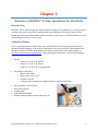
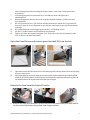
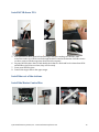
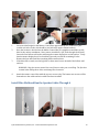
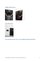
SMARTfit™ High Intensity Cognitive Training SMARTfit™ Trainer Installation Manual for Stud Walls Revision 1.2 2015 Unlike other fitness equipment which may require additional insurance, SMARTfit™ ProTrainer and SMARTfit™ Trainer have been approved by the Fitness Insurance Industry for use under general liability insurance. Please check with your insurer to confirm insurance laws in your state. PARTICIPANTS SHOULD CONSULT A DOCTOR BEFORE STARTING ANY EXERCISE PROGRAM. The content of this workout program is made available with the understanding that Multisensory Fitness, Inc. disclaims all responsibility for any injury incurred as a consequence of engaging in this program without first consulting a physician or otherwise qualified health care professional. Thank You. Enjoy your new SMARTfit™ system! Multisensory Fitness, Inc. www.multisensoryfitness.com © 2015 Multisensory Fitness, Inc. • www.multisensoryfitness.com 2 Table of Contents Table of Contents ...................................................................................................................................... 3 Chapter 1 .................................................................................................................................................................. 4 Welcome to SMARTfit™ Trainer Installation for Stud Walls ..................................................................... 4 Introduction .......................................................................................................................................... 4 Contents of Boxes ................................................................................................................................. 4 Tools Required ...................................................................................................................................... 5 Additional Equipment Required............................................................................................................ 5 Stud Wall Mounting Kit ......................................................................................................................... 5 Site Dimensions......................................................................................................................................... 6 Site Preparation .................................................................................................................................... 6 Prepare the site..................................................................................................................................... 7 Open the Panel Boxes and remove panel marked P1 from the box ..................................................... 9 Remove the lens from the front of Panels ............................................................................................ 9 Create Templates for marking up and setting the panels .................................................................. 10 Use Templates to Mark up location of drill holes ............................................................................... 10 Install the first panel marked P1A....................................................................................................... 10 Install #P1B above P1A........................................................................................................................ 12 Install the rest of the stations ............................................................................................................. 12 Install the Master Control Box ............................................................................................................ 12 Install Wire Mold and Run the Speaker Cables Through it ................................................................. 13 Install the Speaker Cables ................................................................................................................... 15 Install the Speakers ............................................................................................................................. 15 Connect the panel wiring to the Master Control and snap the conduit closed ................................. 16 Complete the wire mold and Power up the system ........................................................................... 16 Replace all the lenses .......................................................................................................................... 17 Clean the lenses .................................................................................................................................. 17 Power up the system refer to user manual for game instructions ..................................................... 17 Apply Flooring Tape ............................................................................................................................ 18 © 2015 Multisensory Fitness, Inc. • www.multisensoryfitness.com 3 Chapter 1 Welcome to SMARTfit™ Trainer Installation for Stud Walls Introduction Welcome. Please read through this manual before starting your installation as it will give you a complete idea of the scope of the installation and ensure things are done in their proper order. Should you have any questions please call our customer service line on: 1-800-900-8542 x 116. We will be happy to assist you in every way. Contents of Boxes Prior to opening any boxes, please inspect the outside of the box for any damage that may have been done during shipping. If the boxes are damaged in any way, please take a photograph of the damage as well as one of the whole delivery and email it with a copy of your delivery note, to: [email protected]. After opening the boxes please check for the following contents: Panels: o Trainer 2 - 4 x 46” x 46” panels o Trainer 3 - 6 x 46” x 46” panels o Trainer 4 - 8 x 46” x 46” Training panels One Master Control Box o Master Control Box o Electrical 10’ power cord o 2 Remote controls o 2 x Square drive screwdriver (clipped inside the master control box) Pair of speakers with brackets. Wire mold/conduit Game manual Stud Wall Mounting Kit Ball kit containing balls, noodles, bean bags, etc. © 2015 Multisensory Fitness, Inc. • www.multisensoryfitness.com 4 Tools Required Electric Drill 1/8” and 1/4” drill bits Hammer Tape measure Level ½” wrench or socket for a 3/8” ratchet Ratchet with 3/8” drive #2 Phillips screwdriver Flat head screwdriver 1/8”and 1/4" flat screwdrivers Hacksaw or PVC cutter Utility knife Extension cord Additional Equipment Required ¾” plywood cut 46” x 92” – 1 per station Stud Wall Mounting Kit © 2015 Multisensory Fitness, Inc. • www.multisensoryfitness.com 5 Chapter 2 Site Dimensions Site Preparation Prior to installation, prepare a sheet of plywood 46” X 92” per panel that will be installed and mount it as a foundation for the station installation. Designate the area where the system will be installed. Verify site location and bring to customer’s attention any outlets that may be covered. Designate the area where the system will be installed and mark off an area 11’ 6” wide by 92” high where the system will be installed. Verify the location to the center of the system where the Master Control will be located and ensure there is an accessible power source. © 2015 Multisensory Fitness, Inc. • www.multisensoryfitness.com 6 Prepare the site 1. 2. 3. There are two options for setting the height of the system: • A. directly on the floor which will make the panels 92” high as illustrated in the pictures above, or, • B. sitting on or just above the baseboards which will make the stations 96” high. Decide whether the systems will sit on the floor or on the baseboard 4” above the floor. For tall people, place the panels on the baseboards. If the system is primarily for use by people under 5’ 8”, then place them directly on the floor. Ensure the wall where the system will be mounted is clear of obstacles so that the plywood backing can mount flush on the wall. © 2015 Multisensory Fitness, Inc. • www.multisensoryfitness.com 7 Install the plywood sheets in the exact location where the Trainer panels will be installed 4. 5. 6. The correct mounting of the plywood sheets will determine the success of the rest of the installation. They need to be flush and level on the front surface to which the Trainer panels will be attached. Using the stud finder, locate the studs and mark off studs that will be used to anchor the plywood panels. (3 studs per panel) Attach the plywood panels to the wall and verify they are flush and level with each © 2015 Multisensory Fitness, Inc. • www.multisensoryfitness.com 8 7. 8. 9. 10. 11. 12. other forming a flat surface marking the location where each of the Trainer panels will be mounted. If mounting the panels on an uneven floor, use shims to ensure the plywood is absolutely level. Anchor the plywood sheets to the studs using the supplied hardware. (2 bolts per stud, 6 per plywood) On a wood stud wall, use a 1/8” drill bit and drill all locations where the ¼” lag bolts will be used 3” deep. (It is very important to pre-drill the wood studs to prevent the wood from splitting). On a metal stud wall, use the impact gun with the 3” self-drilling screws. Use the 2” fender washers at all locations for the plywood. Tighten all 6 bolts per plywood using the 7/16” deep well socket (for wood studs) or the 3/8” socket for the sheet metal studs. Open the Panel Boxes and remove panel marked P1 from the box 13. 14. Open and remove the lids of the boxes of the station panels and lay them in front of wall lying face up in their boxes. Each panel belongs in pairs to make up a station and is numbered #P1A, #P1B, #P2A #P2B, #P3A, #P3B. The top panels are the B panels and include the display board and 5 targets and are installed above the A panels which include just 4 targets. Remove the lens from the front of Panels 1. Remove the front polycarbonate covers from each of the panels and place them back in the box on the Styrofoam to keep them from being scratched. © 2015 Multisensory Fitness, Inc. • www.multisensoryfitness.com 9 Create Templates for marking up and setting the panels Use Templates to Mark up location of drill holes Install the first panel marked P1A 1. Place panel #P1A on the lower left corner of the plywood wall. © 2015 Multisensory Fitness, Inc. • www.multisensoryfitness.com 10 2. 3. 4. If the plywood is 4” above the floor, use the box lid to stabilize the panel on the wall while preparing to screw it into place. Check that it is flush and level before moving to the next step. Screw Panel #1A into place and double check it is flush and level. © 2015 Multisensory Fitness, Inc. • www.multisensoryfitness.com 11 Install #P1B above P1A 5. Place panel #P1B above panel #P1A and bring it into place making sure that the cable connection at the top of #P1A can fit through the hole located at the bottom of #P1B so that it can later connect with the target just above the hole on panel. 6. Set panel #P1B in place above A and double check that it is flush and level so that when #P2A and #P2B are placed next to them, they will fit exactly. 7. Screw panel #P1B in place. 8. Connect the target cable to the upper target. Install the rest of the stations Install the Master Control Box © 2015 Multisensory Fitness, Inc. • www.multisensoryfitness.com 12 1. 2. 3. Locate an ideal height for the Master Control Box, approximately 60” off the floor. (the conduit exit holes on the side should be just below the upper station bracket) Once the location is decided use the Master Control Box as a template to mark the top left hole for the anchor attachment. Next, remove it and drill a 3/8” hole through the drywall. Insert the first hollow wall anchor and hang the remote display box on that anchor. Verify that the master display box is level and then proceed to mark the remaining 3 holes. Remove the box and install the remaining hollow wall anchors. If the holes fall on studs, use the lag bolts or sheet metal screws instead of the hollow wall anchors. WARNING: Keep the master control box out of the area when you are drilling. The fine dust created when drilling these holes can damage the electronics. 4. Attach the master control box with the top two screws only. The bottom two screws will be fastened once the cables and wire mold have been installed. Install Wire Mold and Run the Speaker Cables Through it © 2015 Multisensory Fitness, Inc. • www.multisensoryfitness.com 13 1. 2. 3. 4. 5. 6. 7. 8. 9. 10. Peel off backing of the wire mold only when you are certain where the wire mold will be placed. Do not snap it together. Leave the split open so the cables can be installed at a later time. Press the wire mold temporarily into place. Start running the wire mold from the slots on the side of the master remote display box. Use your level and run the wire mold out of the master display box to the area where the system is located. It is advisable to have a second person standing back confirming that the wire mold is straight. It is important that it “looks right” even if the level tells you otherwise. The wire mold should extend up the side of the system to the top and along the top leaving openings where the panel wiring protrudes. This gap will also be used for the speaker wire to extend up to where the speakers will be located. You will later install T-junctions to cover these gaps. Use a PVC cutter or hack saw to cut the wire mold to exact lengths. © 2015 Multisensory Fitness, Inc. • www.multisensoryfitness.com 14 Install the Speaker Cables 1. 2. 3. 4. 5. 6. 7. 8. Pull the roll of speaker cable from the master control box and separate each cable. Run one end of all three cables through the hole below the switch and up to attach each cable to the green speaker cable connectors. Uncoil the speaker cables and lay them through the wire mold into the master display box. Pay special attention not to twist the cable inside the wire mold since there is not a lot of extra room. Place a tape labeling each cable 1, 2, and 3 to indicate the order they are inserted in the connectors from left to right. Run the other end of the speaker cables through the conduit ensuring they emerge above each panel in the order they were attached in the master control box. This will ensure the sounds for panel 1 will emit from the speaker above panel 1, etc. Tape the Speaker cables up above the panels. Attach wire mold with screws. Install the Speakers 1. Use the speaker brackets as your template for marking the holes needed for mounting the speaker bracket. There should be one centered above each station. 2. Using your marker, mark 4 holes for each speaker bracket onto wall. 3. Drill all 4 holes using your ¼” drill bit. 4. Repeat for each speaker bracket. 5. Hammer the supplied plastic anchors into the holes you just drilled. 6. Mount the speaker bracket into final location using your #2 Phillips screwdriver and the supplied #10 x 1” Phillips screws. 7. Secure speakers using the two speaker knobs and attach cables. © 2015 Multisensory Fitness, Inc. • www.multisensoryfitness.com 15 Connect the panel wiring to the Master Control and snap the conduit closed 8. Uncoil the panel cables and lay them through the wire mold along the top of the panels toward and into the master control box. Pay special attention not to twist the cable inside the wire mold. 9. Once you have all of the cables in place, clip down the wire mold and press it firmly onto the wall at every location. 10. Connect stations to the power interconnect inside the Master Control Box. 11. The power interconnect has six (6) 8-pin connector terminals. Each 8-pin terminal goes to a display board or power source. 12. The station should be connected to the 8-pin connector that is labeled # 1. 13. Power interconnect space #5 is for connecting the display board there in the cover of the master control box. 14. Power interconnect space #6 connects to the 12VDC power supply. Complete the wire mold and Power up the system 15. Plug in one side of your power cable into the right side of the Master Control Box and the other side into the 110V outlet. 16. Power up the system by switching the power switch that is located next to socket where you just installed the power cable. 17. Check to make sure the station powers up correctly and all sensors are operational. 18. Verify all speakers are producing sounds. © 2015 Multisensory Fitness, Inc. • www.multisensoryfitness.com 16 Replace all the lenses Clean the lenses Power up the system refer to user manual for game instructions © 2015 Multisensory Fitness, Inc. • www.multisensoryfitness.com 17 Apply Flooring Tape 1. 2. 3. 4. 5. 6. 7. Clean the floor thoroughly before beginning. Measure from the center of the station and mark the ground at 5’, 8’, 12’ and 20’ out from the wall. Be careful lay the tape parallel to the station. You may try laying a chalk line across the entire length of the floor for more consistent results. At the 5’ mark place a 2’ strip of yellow tape. At the 8’ mark place a 2’ strip of blue tape. At the 12’ mark place a 2’ strip of red tape. At the 20’ mark place a 2’ strip of green tape. © 2015 Multisensory Fitness, Inc. • www.multisensoryfitness.com 18