1
™
playsets
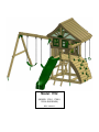
Ovation
Model: 1702
(BOXES: 1700-1, 1700-2,
1702 & SLIDE BOX)
Copyright © 2013 Gorilla Playsets
All Rights Reserved
190 Etowah Industrial Court
Canton, GA 30114
www.gorillaplaysets.com
Please inspect and inventory all parts immediately upon accepting delivery. Use the
inventory pages in the manual to make sure you have received all necessary parts.
The quickest method to get any parts that are missing or damaged is to use our “Quick
Response Center” located at:
www.gorillaplaysets.com/support
DO NOT RETURN THIS PRODUCT TO THE RETAILER OR CONTACT THE RETAILER DIRECTLY.
THE RETAILER DOES NOT STOCK COMPONENTS.
PLEASE RETAIN ALL INSTRUCTIONS FOR FUTURE REFERENCE. KEEP THEM IN A SAFE
PLACE WHERE YOU CAN REFER TO THEM AS NEEDED. CHECK FOR REVISED INSTRUCTIONS AT:
www.gorillaplaysets.com/manuals
GORILLA PLAYSETS WARRANTY - 2013
Gorilla Playsets® (“Gorilla”) warrants its play sets to be free from defects in workmanship and materials, under
normal use and conditions, for 10 years for above ground structural wood components and for one year for all
other components (e.g., swings, hardware, plastics, tarps, rope ladder, etc.).
Gorilla warrants all remaining products, including but not limited to its Breckenridge Playhouse™, Free Standing
Swing Set, Free Standing Tire Swing, See-Saw, Children’s Picnic Table with Umbrella, Play-Zee-Bo™ and spring
riders to be free from defects in workmanship and materials, under normal use and conditions, for a period of 1
year.
Cosmetic imperfections and natural tendencies of wood such as peeling, splintering, warping, seasonal checking
or cracking, knots or knot holes, etc. are normal characteristics of all outdoor wooden play equipment and are
not covered by this warranty.
Wood rot or decay that develops because the product was installed in an area with poor drainage is not covered
under this warranty. Lumber that has been damaged by wood boring bees, or conditions that develop as a result of
faulty or improper installation of the product, are not covered by this warranty. Fading of stain, discoloration or
mold on any wood part or accessory is not covered by this warranty. Cracks in plastic components, surface rust on
hardware and chips on powder coated materials are not considered defects in material as long as they do not
affect the functionality or structural integrity of the part or component.
It is the owner’s responsibility to maintain the swing set. This includes but is not limited to re-staining and
resealing the lumber as needed and regular inspection to be sure all hardware is tight. Instructions for proper
maintenance can be found on Gorilla’s website. Imperfections or conditions that develop because of a failure to
properly maintain the swing set are not covered by this warranty.
Gorilla will repair or, at its discretion, replace any above ground part within the stated warranty period that is
defective in workmanship or materials. This decision is subject to verification of the defect, which, at Gorilla’s
discretion, may be accomplished by submitting photographs or by delivery of the defective part to Gorilla Playsets
• 190 Etowah Industrial Ct. • Canton, GA 30114 • 1-800-882-0272 Monday to Friday 9AM-5PM EST. Any warranty
claim must include proof of purchase, including the date of purchase. In addition, within the first 30 days from the
date of purchase, Gorilla will replace any parts discovered to be missing from or damaged in the original packaging.
This warranty is valid only if the product is used for the purpose for which it was designed and installed at a
residential, single-family dwelling. This warranty is void if the product is used in a commercial, institutional or
multi-family setting. This warranty does not cover normal wear and tear or (a) products that have been damaged
by acts of God and/or nature, negligence, misuse or accident; (b) products that have been modified or repaired
by unauthorized persons; (c) the cost of labor; or (d) the cost of shipping any replacement product or part.
GORILLA DISCLAIMS ALL OTHER REPRESENTATIONS AND WARRANTIES OF ANY KIND, EXPRESSED, IMPLIED,
STATUTORY OR OTHERWISE, INCLUDING THE IMPLIED WARRANTIES OF MERCHANTABILITY AND FITNESS FOR A
PARTICULAR PURPOSE. GORILLA WILL NOT BE LIABLE FOR ANY INCIDENTAL OR CONSEQUENTIAL DAMAGES. This
warranty is non-transferable and does not extend to the owners of the product subsequent to the original
purchaser. Some states do not allow limitations on implied warranties or exclusion of incidental or consequential
damages, so these restrictions may not be applicable to you. This warranty gives you specific legal rights. You may
also have other rights which vary from state to state.
IMPORTANT SAFETY GUIDELINES
This product is recommended for use by children ages 3-11. This product is intended
for residential use only and not intended for use in any public setting. A safety surface
such as mulch or recycled tire should be used under the play set to prevent injury from
falls. Also a 6 foot safety zone should be used around the entire play set.
As with any home project, good judgment and respect for power tools will greatly
reduce the risk of injury. Gorilla recommends you follow all tool manufacturers’ safety
guidelines. Always wear eye protection and safety gloves to prevent injury. In several
phases of construction two people may be required for lifting and securing of lumber.
While the play set is being constructed, please keep children off the equipment until the
project is complete. Bolts and screw heads should be checked regularly for tightness.
The ground ladder, rope ladder, slide, swings and other areas where children spend a
majority of their playtime should be checked more frequently.
Gorilla shall not be liable for incidental, indirect or consequential damages or
injuries that result from building and/or playing on our play sets. Adult supervision is
recommended anytime a play set is being used.
WEIGHT LIMITS FOR GORILLA PLAYSETS
• FORT PLATFORMS: 800 LBS. TOTAL WEIGHT
• SWING BELT: 225 LBS.
• GLIDER SWINGS: 70 LBS. PER CHILD. UP TO 140 LBS. TOTAL WEIGHT.
• TRAPEZE: 125 LBS.
• FULL BUCKET SWING/ HALF BUCKET SWING: 50 LBS.
• HEAVY DUTY TODDLER BUCKET SWING: 85 LBS.
• INFANT SWING: 35 LBS.
• TIRE SWING: 125 LBS. TOTAL WEIGHT
• ROPE LADDER: 75 LBS.
• ROCK WALL: 150 LBS.
• CLIMBING RAMP: 150 LBS.
• MONKEY BARS: 175 LBS.
• ALL SLIDES: 150 LBS.
Gorilla recommends that the weight limits for all components must not be exceeded.
Failure to adhere to these and other safety guidelines could result in damage to the play
set and injury to the users.
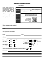
WARRANTY REGISTRATION
- OVATION Gorilla Playsets manufactures
ƚŚĞ ĮŶĞƐƚ ƋƵĂůŝƚLJ ƉƌŽĚƵĐƚƐ ƚŚĂƚ
ĂƌĞ ĚĞƐŝŐŶĞĚ ĨŽƌ ŽƵƚƐƚĂŶĚŝŶŐ
ƐƚƌĞŶŐƚŚ ĂŶĚ ĚƵƌĂďŝůŝƚLJ͘ tĞ
ďĂĐŬ ŽƵƌ ƉƌŽĚƵĐƚƐ ǁŝƚŚ ĂŶ
ƵŶƉĂƌĂůůĞůĞĚ ǁĂƌƌĂŶƚLJ͘ /Ŷ ƚŚĞ
ƵŶůŝŬĞůLJĞǀĞŶƚƚŚĂƚLJŽƵǁŝůůŶĞĞĚ
ƚŽ ĐŽŶƚĂĐƚ ƵƐ ĂďŽƵƚ ĐŽǀĞƌĞĚ
ƌĞƉĂŝƌƐ͕ ǁĞ ŵƵƐƚ ŚĂǀĞ Ă ǀĂůŝĚ
tĂƌƌĂŶƚLJZĞŐŝƐƚƌĂƟŽŶŽŶĮůĞ͘
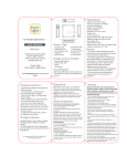
3 EASY WAYS TO REGISTER
KWd/KEϭ
&ĂdžƚŚŝƐĐŽŵƉůĞƚĞĚĨŽƌŵƚŽ͗
(678) 880-3329
OR
DĂŝůƚŚŝƐĐŽŵƉůĞƚĞĚĨŽƌŵƚŽ͗
Gorilla Playsets
ϭϵϬƚŽǁĂŚ/ŶĚƵƐƚƌŝĂůŽƵƌƚ
ĂŶƚŽŶ͕'ϯϬϭϭϰ
ŽŵƉůĞƚĞƚŚĞŽŶůŝŶĞƌĞŐŝƐƚƌĂƟŽŶĨŽƌŵĂƚ͗
ŚƩƉ͗ͬͬǁǁǁ͘ŐŽƌŝůůĂƉůĂLJƐĞƚƐ͘ĐŽŵͬƌĞŐŝƐƚĞƌ
KWd/KEϮ
^ĐĂŶƚŚŝƐYZŽĚĞ
ǁŝƚŚLJŽƵƌƐŵĂƌƚ
ƉŚŽŶĞƚŽĐŽŵƉůĞƚĞ
ƚŚĞĨŽƌŵƵƐŝŶŐLJŽƵƌ
ƉŚŽŶĞ
KWd/KEϯ
Where did you buy this product?:
Date of
Purchase
Place of Purchase
zŽƵƌƌĞŐŝƐƚƌĂƟŽŶŝŶĨŽƌŵĂƟŽŶ͗
Name:
ĚĚƌĞƐƐ͗
Email:
Street
Please select
LJŽƵƌĂŐĞ͍
,ŽǁŽůĚĂƌĞ
LJŽƵƌĐŚŝůĚƌĞŶ͍
City
18-30
41-50
31-40
51+
2-3
6-7
4-5
8+
ŝƉ
,ŽǁǁŽƵůĚ
you rate the
ƋƵĂůŝƚLJŽĨ
ƚŚŝƐƉƌŽĚƵĐƚ͍
tŽƵůĚLJŽƵƌĞĐŽŵŵĞŶĚƚŚŝƐƉƌŽĚƵĐƚƚŽĨƌŝĞŶĚƐΘĨĂŵŝůLJ͍
Comments:
State
Excellent
ďŽǀĞǀĞƌĂŐĞ
ǀĞƌĂŐĞ
ĞůŽǁǀĞƌĂŐĞ
Poor
Yes
No
IMPORTANT – PLEASE READ
As fresh lumber acclimates to its new environment, the natural tendencies of the tree can show
itself in the form of checks, or “cracks” in the lumber. In almost all cases this is normal and it will
not affect the structural integrity of your play set.
Cosmetic defects that do not affect the structural integrity of the product, or natural defects of
wood such as warping, checking or any other physical properties of wood that do not present
a safety hazard, are not covered by this warranty. Defects that develop because the product is
exposed to extreme climate conditions or woodboring insects are not covered by this warranty.
Defects that develop as a result of faulty or improper installation of the product are also not
covered by this warranty.
Most cracks are not warrantable, however if you believe that the integrity of your play set is
compromised by this natural occurrence, please follow the warranty claim procedure found at
www.gorillaplaysets.com. Click on the “Customer Care” tab on the left hand side of the page,
then click on “Warranty Claim” and follow the directions.
KEEPING YOUR PLAYSET LIKE NEW
LUBRICATE:
• Spray swing hangers with Pam, Mazola or olive oil to stop squeaking.
• Do not use petroleum based products such as WD-40 or motor oil.
• To speed up the slide wipe center of slide ONLY with wax paper every 2 - 3 weeks.
TIGHTEN:
• Check and tighten hex/carriage bolts within first 60 days and then twice annually.
• Check lag screws for tightness before each season and then once during the season for
tightness. Tighten lag screws as required.
SEAL:
• Apply an oil based sealer or preservative within 90 days, then every 2 - 3 years. You may
need to power wash the unit before sealer application on year two.
INSECTS:
• To repel yellow jackets and wasps, using a cloth, coat all interior 90 degree corners with liquid
dish soap underneath the play set deck. This will make wasps sick when they attempt to build a
nest. Avoid using insecticides.
Model: 1702
(BOXES: 1700-1, 1700-2,
1702 & SLIDE BOX)
REV: 3.8.2013
TABLE OF CONTENTS
Safety Guidelines……………………………………….......……...........................Pages 3-6
Leveling Fort, General Information and Definitions…………………...................Pages 6-8
How to Install T-nuts, Board Identification, Predrill Lag Screw Directions and
Swing Beam Loading........................................................................................Pages 9-13
Site Plan, Required Tool List and Kit Contents...............................................Pages 14-15
Hardware, Lumber and Accessory Checklists.………………………………....Pages 16-30
Arranging Corner Posts and adding T-Nuts to Corner Posts..………...…............ Step 1-2
Framing Fort……………………………………..…………………………..……..... Steps 3-9
Mounting Fort Side Supports…....……………….…………...….............................. Step 10
Rock Wall Assembly...................…………………...…..……..……...….…….... Steps 11-15
Adding Deck Boards, Stringer and Front Face Board.................................... Steps 16-18
Swing Beam Plate, Swing Hangers and Swing Beam Mount/Trap Arm......... Steps 19-21
Ladder Assembly and Installation…………………..……........…..................... Steps 22-23
Swing Beam Assembly...........……...……………………….….........……......... Steps 24-28
Center Posts, Window Supports/Windows…………………………………...... Steps 29-30
Tarp Boards, Panel Slats.…………………………......….…............................. Steps 31-32
Tic Tac Toe Assembly/Installation…………………………….....……................. Step 33-34
Roof Assembly................................................................................................ Steps 35-44
Steering Wheel, Wave Slide, Climbing Rope….............................................. Steps 45-47
Flag Kits, Name Plate, Hanging Swings/Trapeze, Ground Stakes …...…..... Steps 48-51
Safety Handles ..................................................................................................... Step 52
PLEASE READ OWNER’S MANUAL CAREFULLY
BEFORE STARTING ASSEMBLY!
2
Safety and Maintenance Tips for Your New Play Set:
NOTE: Your children’s safety is our #1 concern. Observing the
following statements and warnings reduces the likelihood of serious
or fatal injury. Please review these safety rules regularly with your
children.
• This play set is designed for the use of 4 occupants who have a combined weight not
exceeding 800 pounds on the elevated floor, 3 occupants who have a combined weight
of 425 pounds on the swing area, for a total Unit capacity of 7 occupants who have a
combined weight of 1225. (This weight does not include any picnic table area(s).)
• On-site adult supervision is required.
• Teach children not to walk close to, in front of, behind, or between moving swings or
other moving playground equipment.
• Teach children to sit in and never stand on swings
• Teach children not to twist the chains and ropes and not to loop them over the swing
beam, since this may reduce the strength of the chain or rope.
• Teach children not to jump from swings or other playground equipment in motion.
• Teach children not to push empty seats. The seat may hit them and cause serious
injury.
• Teach children to sit in the center of the swings with their full weight on the seats.
• Teach children not to use the equipment in a manner other than intended.
• Teach children to always go down slides feet first. Never slide headfirst.
• Teach children to look before they slide to make sure no one is at the bottom.
• Teach children to never run up a slide, as this increases their chances of falling.
• The parents should have the children dress appropriately with well-fitting shoes. Loose
clothing such as scarves and ponchos should not be worn. Always take off, tie up or
tuck in cords and drawstrings on children’s clothing. These things can get caught on
playground equipment and strangle a child.
• Teach children not to climb when the equipment is wet.
• Teach children to never jump from a fort deck. They should always use the ladder,
ramp or slide.
• Teach children to never crawl or walk across the top of monkey bars.
• Teach children to never crawl on top of a fort roof.
• Verify that any suspended climbing ropes, chains, or cables are secured at both ends
and that they cannot be looped around an adult hand.
• Teach children not to attach items to the playground equipment that are not specifically
designed for use with the equipment, such as, but not limited to, jump ropes, clothesline,
pet leashes, cables and chain as they may cause a strangulation hazard.
• Teach children to never wrap their legs around swing chain.
• Teach children to never slide down the swing chain.
• Teach children to remove their bike or other sports helmet before playing on the
playgound equipment.
• Teach children to NEVER look at the sun or other bright light through any accessory
such as but not limited to a telescope, periscope or binoculars.
WARNING: Children must NOT use this play set until it has been
completely assembled and inspected by an adult to insure it has been
properly installed and the swing beam legs are anchored.
3
Safety and Maintenance Tips for Your New Play Set:
(continued)
Playgrounds should be inspected on a regular basis. If any of the following conditions are noted,
they should be removed, corrected, or repaired immediately to prevent injuries.
• Hardware that is loose, worn or that has protrusions or projections.
• Exposed equipment footings.
• Scattered debris, litter, rocks, or tree roots.
• Splinters, large cracks, and decayed wood components.
• Deterioration and corrosion on structural components, which connect to the ground.
• Missing or damaged equipment components, such as handholds, guardrails, swing seats.
• Check all nuts and bolts twice monthly during the usage season and tighten as required.
(But not so tight that you crack the wood) We recommend you check the swing beam and
hardware often due to wood expansion and contraction. It is particularly important that this
procedure be followed at the beginning of each season.
• Remove plastic swing seats and take indoors or do not use when the temperature drops below
32°F. Reinstall swings and other swing equipment at the beginning of the usage season.
• Oil all metallic moving parts monthly during the usage period.
• Check all coverings for bolts and sharp edges twice monthly during usage season to be certain
they are in place. Replace when necessary. It is especially important to do this at the beginning
of each new season.
• Check swing seats, ropes, cables and chains monthly during usage season for evidence of
deterioration. Replacement should be made of any swing seat that has developed cracks in the
plastic seats. Ropes, cables and chains should be removed and replaced if excessive wear is
found. Contact us for warranted replacement parts.
• For rusted areas on metallic members such as monkey bars, hand supports brackets, etc.;
sand and repaint, using a non lead-based paint meeting the requirements of Title 16 C.F.R. Part
1303. These requirements are available at: http://www.cpsc.gov/
• Inspect wood parts monthly. The grain of the wood sometimes will lift in the dry season
causing splinters to appear. Light sanding may be necessary to maintain a safe playing
environment. If you are treating your play set with stain regularly, it will help prevent severe
checking/splitting and other weather damage.
• Once or twice a year, depending on your climate conditions, you must apply some type of
protection (sealant) to the wood of your unit. Prior to the application of sealant, lightly sand any
“rough” spots on your set. Please note this is a requirement of your warranty.
• Creating and maintaining the play set on a level location is very important. As your children
play, your play set will slowly dig its way into the soil, and it is very important that it settles
evenly. Make sure the play set is level and true once each year or at the beginning of each play
season.
• Twice a month during the usage season rake the playground protective surfacing materials to
prevent compaction and maintain appropriate depths. Replace the protective surfacing materials
as required.
• Disposal Instructions: When the play set is no longer desired, it should be disassembled and
disposed of in such away that no unreasonable hazards will exist at the time the play set is
discarded.
4
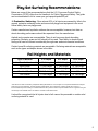
Play Set Surfacing Recommendations:
Below are some of the recommendations that the U.S. Consumer Product Safety
Commission (CPSC) offers from its Handbook for Public Playground Safety. The guide
can be downloaded in full at www.cpsc.gov/cpscpub/pubs/325.pdf
1. Protective Surfacing - Since almost 60% of all injuries are caused by falls to the
ground, protective surfacing under and around all playground equipment is the most
critical safety factor on playgrounds.
Certain manufactured synthetic surfaces also are acceptable; however, test data on
shock absorbing performance should be requested from the manufacturer.
Asphalt and concrete are unacceptable. They do not have any shock absorbing
properties. Similarly, grass and turf should not be used. Their ability to absorb shock
during a fall can be reduced considerably through wear and environmental conditions.
Certain loose-fill surfacing materials are acceptable. Surfacing materials are acceptable,
such as the types and depths shown in the table.
Fall Heights and Materials
Type Of Material
6 in. depth
9 in. depth
12 in. depth
Double-Shredded bark mulch
Wood Chips
Fine Sand
6’ Fall Height
6’ Fall Height
5’ Fall Height
10’ Fall Height
7’ Fall Height
5’ Fall Height
11’ Fall Height
12’ Fall Height
9’ Fall Height
Shredded Tires*
Fine Gravel
10-12’ Fall Height
6’ Fall Height
N/A
7’ Fall Height
N/A
10’ Fall Height
*This data is from tests conducted by independent testing laboratories on a 6-inch depth of uncompressed shredded tire samples
produced by four manufacturers. The tests reported critical heights, which varied from 10 feet to greater than 12 feet. It is
recommended that persons seeking to install shredded tires as a protective surface request test data from the supplier showing the
critical height of the material when it was tested in accordance with ASTM F1292.
It should be recognized that all injuries due to falls cannot be prevented no matter what
surfacing material is used.
5
2. Fall Zones - A fall zone, covered with a protective surfacing material, is essential
under and around equipment where a child might fall. This area should be free of other
equipment and obstacles onto which a child might fall. Stationary climbing equipment
and slides should have a fall zone extending a Minimum of 6’ in all directions from the
perimeter of the equipment.
Swings should have a fall zone extending a minimum of 6’ from the outer edge of the
support structure on each side. The fall zone in front and back of the swing should
extend out a minimum distance of twice the height of the swing as measured from the
ground to the top of the swing support structure.
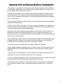
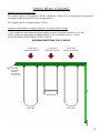
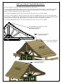
LEVELING YOUR FORT DURING ASSEMBLY
• Complete the steps which will be the basic frame of the fort. {i.e. four corner posts with
base (sand box boards) and deck supports}
• Position in the most level area chosen for the play set, keeping in mind the location
and size of the swing beam, ladder, slides, etc. that extend off the fort.
• Once the frame is in the final position, check for vertical and horizontal levelness to
determine which side(s) will need to be dug into the ground to level the play set.
• With a shovel, score the ground around the outside edges of the sandbox boards on
the ‘high’ side of the fort. This is the area that will be dug in. Make sure to score deep
enough; the scored lines will be your digging template.
• Push the frame off and away from the scored area, far enough to dig and remove dirt
to reach the appropriate depth.
• Dig a channel along the scored line(s) for the base of the fort (corner post and
sandbox boards) to rest into. Dig the channel(s) to the same level depth. The bottom
of the channel(s) should be level to each other so your frame doesn’t teeter or rock
because the channel(s) are uneven.
• Once you have removed enough grass and dirt, slide/push the frame into the
channel(s). Place a level on the vertical and horizontal boards of the frame to determine
if enough soil, or too much, was removed.
• Repeat this process until the basic frame is plumb and level and in its final position
before completing the rest of the assembly.
• Measure to make sure fort is square.
Important: if you require a channel depth of more than 6”, then we
recommend you have your play set area professionally graded before
completing assembly.
Example Play area:
Side View of
Playset Frame
(Grade is the
Slanted Line)
The diagonal measurements should be the
same from corner post to
corner post. If not, adjust
corner posts so that the
distance is equal.
= Area to be scored and
channeled for levelness
6
General Info to Review Before Installation
• Depending on your experience, assembly of the playset can take as little as 6 hours
up to 24 hours, depending on size, after inventory of parts; therefore, we recommend
you set aside a full two days for assembly.
• Identify all of the parts for your play set. Empty each box and lay out boards so you
can see each part. Your instruction book will have detailed drawings that will make it
easy for you to recognize individual parts. Keep all hardware and metal parts separate
from wooden pieces.
• After everything is laid out, check carefully to ensure all parts are present. Make sure
there are no broken boards.
• Find an area to sort your hardware. It is best to open the hardware on a solid surface
so that you do not lose any pieces in the grass. This will save time and familiarize you
with all the different pieces in the hardware bag.
• Important note: Wood has some natural defects such as knots, surface cracks, etc…
We reject parts that are structurally defective. We use a high quality lumber in our
structures; however, you should inspect each part for splinters or rough spots and sand
them smooth to prevent injury.
• After familiarizing yourself with all of the components, read all instructions thoroughly.
Reading instructions after you have studied the parts will help you understand the
installation process, and help to eliminate unnecessary mistakes.
• Pay close attention to the diameter and length of each bolt and screw.
• Never tighten hardware completely at first. It helps to have some adjustment for bolt
alignment while you are attaching parts together. After everything is square, tighten
each joint.
• After the main unit is assembled it is critical that the floor is level and square. If the
main frame is not level, the walls and floor will be out of square.
• After you complete installation, make sure every bolt, screw, and nut is tight, and every
board is secure. Wood will expand and contract with the seasons.
• Place the set on level ground, not less than 6 feet from any structure or obstruction
such as a fence, garage, house, overhanging branches, laundry lines, or electrical
wires.
7
This page is a list of definitions and explanations used throughout our
instructions to aid you in the assembly of your play set.
Offset Holes- Throughout the installation procedures we will refer to parts with offset
holes. This refers to the orientation of the holes on the board. An offset hole is one that
is closer to one side than it is the other or in other words, it is not centered on the board.
In the procedures you will be instructed to attach the boards with the holes offset up or
with the holes offset down. This refers to which side of the board the hole/holes should
be closer to. Offset holes up= hole/holes will be closer to the top of the board. Offset
holes down= hole/holes will be closer to the bottom of the board. Note: some parts do
not have offset holes, but instead the holes are on center. Therefore there will not be
any reference on how to offset these parts.
EXAMPLE OF OFFSET HOLES UP
EXAMPLE OF OFFSET HOLES DOWN
Counter-sunk holes - Many of the parts that will be used have counter-sunk holes. A
counter-sunk hole is one that surrounds one side of a through hole, but does not extend
through the wood it’s self. When using a counter-sunk hole the bolt will be inserted
through the through hole and either the head of the bolt and washer or nut and washer
will occupy the counter sunk hole.
Counter-Sunk Hole
Through Hole
Lag Screws- Lag screws are used in the construction of our play sets to enhance
the structural integrity of the unit. There will not be predrilled holes in the post for lag
screw installation. Lag screws are self-tapping, though if you are using a manual socket
wrench it may be advantageous to pre-drill a hole first. Instructions for this are provided
on a separate page in the front of the manual. Be sure to tighten the lags completely
when driving them in by hand. Power tools such as a heavy duty impact driver or large
power drill should have enough torque to drive in the lag screws, but make sure not to
over tighten as this can cause the threads to “strip out” in the post.
8
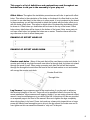
Common Installation Practice Installing T-nuts
When installing T-nuts into the wood, use a smooth faced hammer to set the face of the
T-nut flush into the wood
Corner Post
T-nut
This picture shows the T-nut inserted
and installed flush to the wood.
Flush (Correct)
Insert the barrel of the T-nut into the
predrilled hole. Using a smooth faced
hammer, drive the T-nut until the face
of the T-nut is flush to the wood.
This picture shows an end view of the T-nut
installed flush to the wood.
WARNING: DO NOT EMBED THE TOP
OF THE T-NUT INTO THE
FACE OF THE WOOD
Cross Section end view, you are looking at an X-ray view
of the post and T-nut. The barrel of the T-nut is in the
corner post the line is the face of the wood.
9
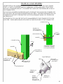
HOW A T-NUT WORKS
THE FIRST STEP IN OUR ASSEMBLY INSTRUCTIONS IS TO INSERT T-NUTS INTO THE CORNER
POSTS. A T-NUT IS A FASTENER WHICH IS THREADED ON THE INSIDE AND IT FUNCTIONS
JUST LIKE A STANDARD HEX NUT. YOU INSERT THE T-NUTS INTO THE PREDRILLED HOLES IN
THE CORNER POSTS.
THE T-NUT HAS A BARREL SHAPED END WHICH GOES INTO THE HOLE IN THE CORNER POST.
THE T-NUT ALSO HAS AN FLANGE SHAPED END WITH TEETH. THE TEETH PENETRATE INTO THE
CORNER POST WOOD TO PREVENT THE T-NUT FROM SPINNING WHEN YOU TIGHTEN THE
HEX HEAD BOLT.
SHOWN BELOW YOU WILL SEE THE T-NUT IS HAMMERED INTO THE CORNER POST ON THE
BACK SIDE. THE BOARD IS BEING ATTACHED ON THE FRONT SIDE OF THE CORNER POST.
CORNER POST
BOARD YOU
ARE ATTACHING
TO CORNER POST.
T-NUT
FLANGE
IS HERE.
HEX HEAD BOLT
WASHER
CORNER POST
T-NUT
A
CROSS SECTION VIEW
OF BOARD, CORNER
POST AND FASTENERS.
WASHER
BACK SIDE OF
CORNER POST
T-NUT DETAILS
BOARD YOU ARE
ATTACHING TO
CORNER POST.
FLANGE
SHAPED END
WITH TEETH
TEETH
FRONT SIDE OF
CORNER POST
HEX HEAD BOLT
THREADS ON
INSIDE OF
BARREL .
BARREL
SHAPED
END GOES
INTO HOLE IN
CORNER POST.
DETAIL A
SCALE 2 : 1
10
BOARD IDENTIFICATION
1. On the end of each board there should be a small white tag that is stapled into place.
2. This white identifcation tag displays the thickness, width, length and an abbreviated
description of the part.
Example: a tag reads "2-4-3600-BPB"
•
The 2 is the thickness of the board. "Nominal Lumber" at a home center will measure 11/2" for the thickness. We "remill" that lumber to 1-3/8" thick.
•
The 4 is the width of the board. "Nominal Lumber" at a home center will measure 31/2" for the width. We "remill" that lumber to 3-3/8" wide.
Note: sometimes the width will be smaller than 3-3/8" because:
A) We need the width of the part to fit into a certain area of the play set.
B) We need the designation to be simple.
•
The 3600 is the length of the board. It means the board is 36 inches long. If the code
were 3625 then the board is 36-1/4" in length.
•
The "BPB" abbreviation stands for "Bottom Panel Board". The wood part bill of materials
in the instructions has a description which will match the abbreviation closely.
•
In the event that there is no tag on a wood part measure the part then:
A)Use the measurements and compare them to the wood list at the front of the
instructions to identify it.
B)Look at the holes on the wood part and compare them to the pictures in the wood
list.
C)Look to see if the holes are centered or if they are offset up or offset down.
This should help you identify any parts that have missing tags. In the event that you
cannot identify a board please email us for assistance.
36" LENGTH
3
18"
THICKNESS
2-4-3600-BPB
3
3 8 " WIDTH
TAG
11
PRE-DRILL LAG SCREW DIRECTIONS
Pre-drilling holes for lag screws will make it easier to drive the screws in by hand.
"Jobber" length drill bits are available in sizes that are longer than standard drill bits and
those are ideal for the job. When using the drill bit you will have to "spot" drill the post
and then remove the board you are attaching to finish drilling the hole.
Pay attention to the DIAMETER of the lag screw you are installing. Your playset may
come with two different diameter lag screws. Each diameter will require a different size
drill bit. When installing lag screws DO NOT OVERTIGHTEN.
LAG SCREW DIAMETER
DRILL BIT SIZE
5/16" DIAMETER
9/64"
3/8" DIAMETER
11/64"
Corner Post
2 x 4 board
Example: 3/8" diameter x 3-1/2" lag screw
This would be like the 2 x 4 board installation shown
below. Place the board into position. Spot Drill through
the holes in the 2 x 4 board into the corner posts with
an 11/64" drill bit. Remove the 2 x 4 board. Continue
to drill the holes to a total depth of 2-5/16" as shown at
the right. Install the 2 x 4 board.
7
3 16 "
5
2 16 "
Example 5/16" diameter x 3-1/2" lag screw
This would be like the 2 x 4 board installation shown
below. Place the board into position. Spot Drill through
the holes in the 2 x 4 board into the corner posts with
an 9/64" drill bit. Remove the 2 x 4 board. Continue to
drill the holes to a total depth of 2-5/16" as shown at
the right. Install the 2 x 4 board.
Example 3/8" diameter x 5" lag screw
This would be like the 4 x 4 board
installation shown below. Place the
board into position. Spot drill through the
holes in the 4 x 4 board into the corner
posts with an 11/64" drill bit. Remove the
4 x 4 board. Continue to drill the holes to
a total depth of 2-13/16" as shown at the
right. Install the 4 x 4 board.
Corner Post
4 x 4 board
Corner Post
Corner post
13
2 16 "
2 x 4 board
4 x 4 board
15
4 16 "
12
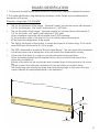
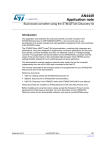
SWING BEAM LOADING
Weight Limits for Accessories:
The weight limit for a Swing Belt is 225 lbs. (Although 150lbs is the maximum recommended
swinging weight capacity for the swing position.)
The weight limit for a Trapeze Bar is 125 lbs.
Maximum Allowable swinging weight for a three position swing:
1) The maximum allowable swinging weight at each Swing Belt position is 150 lbs.
2) The maximum allowable swinging weight at the Trapeze position is 125 lbs.
3) The MAXIMUM SWING BEAM LOAD IS 425 lbs.
MAXIMUM SWING BEAM LOAD IS 425 LBS.
150 LBS MAX
SWINGING WEIGHT
125 LBS MAX
SWINGING WEIGHT
150 LBS MAX
SWINGING WEIGHT
THIS END
OF SWING
BEAM IS
ATTACHED
TO PLAY SET.
TRAPEZE BAR
SWING BELT
SWING BELT
REV A: 8/29/2012
13
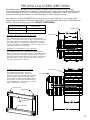
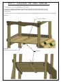
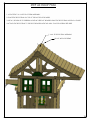
1700 SERIES - WOOD ROOF
Ovation/Passage Elite?
Please familiarize yourself with the manual, parts/components and general
1
construction
process
Height -10'
- 7- " of your new playset before getting started.
16
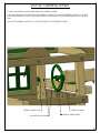
SITE PLAN:
Trapeze Arm (1)
5
14'-6 8 "
5
6'-5 8 "
Rock Wall
3
3'-11 8 "
15
13'-8 16 "
Wave Slide
Ladder
Swing Belts (2)
Playset height: 10 feet - 7 inches
Swing Beam height: 7 feet - 2-1/2 inches
Deck Height: 4 feet
Approximate assembly time: 6-8 hours
(6) foot unobstructed safety perimeter around playset recommended
14
REQUIRED TOOL LIST:
___ Standard or Cordless Drill w/ Phillips Bit (#2 square bit provided)
___ Drill Bits 1/8”, 3/8”, 9/64”, 11/64” and a 7/8” Paddle style bit.
___ ½” Wrench and Socket
___ ½” Deep Well Socket
___ 9/16” Deep Well Socket
___ 9/16” Wrench and Socket
___ Level
___ Tape Measure
___ Extension Cord (if using standard drill)
___ Hammer
___ Pencil
___ Locking Pliers (Vise Grips)
___ Shovel
___ 2-1/2” Spring Clamps (See Step 40)
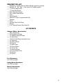
KIT CONTENTS
Swings, Slides, Accessories:
___ (Qty ) Description
___ (2) Swingbelt w/Chains
___ (1) Trapeze Swing w/Chains
___ (1) Wave Slide
___ (10) Rock Wall Grips (assorted colors)
___ (1) Telescope
___ (2) Safety Handle
___ (2) Flag Kit
___ (1) Name Plate
___ (4) Ground Stake
___ (1) Tic Tac Toe
___ (1) Steering Wheel
___ (1) Crown (Plastic Sun)
___ (2) Window
___ (1) Screen
Fort Hardware:
see following pages
Swing Beam Hardware:
see following pages
Wood Components:
see following pages
15
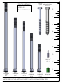
1700/1701 HARDWARE
#8 X 1-1/4"
WOOD SCREW
QTY: 6
PAGE: 1 OF 2
REV A: 10/29/2012 JH
#8 X 1-1/2"
WOOD SCREW
QTY: 8
#14 X 1-1/4"
PAN HEAD SCREW
QTY: 8
#8 X 1-3/4"
WOOD SCREW
QTY: 20
9
8
#8 X 2"
WOOD SCREW
QTY: 161
7
#8 X 2-1/2"
WOOD SCREW
QTY: 28
#8 X 3"
WOOD SCREW
QTY: 14
6
5/16" TEE NUT
QTY: 44
3/8" LOCK NUT
QTY: 21
5
4
3/8" WASHER
QTY: 33
TORQUE WASHER
QTY: 19
3
2
5/16" WASHER
QTY: 48
1
5/16 X 4-1/2"
HEX BOLT
QTY: 34
5/16 X 2-1/2"
HEX BOLT
QTY: 6
5/16 X 1-1/2"
HEX BOLT
QTY: 4
1/4" WASHER
QTY: 8
USE THE RULER TO THE RIGHT TO MEASURE YOUR BOLTS AND SCREWS. PICTURE VIEWS SHOWN
ABOVE ARE 1:1 SCALE AND CAN BE USED TO MATCH BOLT AND SCREW SIZES.
16
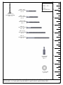
1700/1701 HARDWARE
PAGE: 2 OF 2
5/16" X 3-1/2"
3/8 X 3-1/2"
HEX LAG
HEX LAG SCREW
SCREW
QTY: 12
QTY: 4
9
REV A: 10/29/2012 JH
8
7
6
5
4
3
#2 SQUARE
DRIVE TIP
QTY: 1
2
1
3/8 x 9"
CARRIAGE
BOLT
QTY: 1
3/8" x 7"
CARRIAGE
BOLT
QTY: 8
3/8 x 6-1/2"
CARRIAGE
BOLT
QTY: 6
3/8 x 5"
CARRIAGE
BOLT
QTY: 4
3/8 x 3-1/2"
CARRIAGE
BOLT
QTY: 2
PLASTIC
BOLT CAP
QTY: 21
USE THE RULER TO THE RIGHT TO MEASURE YOUR BOLTS AND SCREWS. PICTURE VIEWS SHOWN
ABOVE ARE 1:1 SCALE AND CAN BE USED TO MATCH BOLT AND SCREW SIZES.
17
1702 HARDWARE
PAGE: 1 OF 1
#8 X 1-1/4"
WOOD SCREW
QTY: 4
#14 X 1-1/4"
PAN HEAD SCREW
QTY: 16
REV A:
10/30/2012 JH
#8 X 1-1/2"
WOOD SCREW
QTY: 2
9
8
#8 X 1-3/4"
WOOD SCREW
QTY: 7
7
#8 X 2"
WOOD SCREW
QTY: 86
#8 X 2-1/2"
WOOD SCREW
QTY: 2
6
#8 X 3"
WOOD SCREW
QTY: 2
5
4
#2 SQUARE
DRIVE TIP
QTY: 1
3
2
1/4" WASHER
QTY: 16
1
USE THE RULER TO THE RIGHT TO MEASURE YOUR BOLTS AND SCREWS. PICTURE VIEWS SHOWN
ABOVE ARE 1:1 SCALE AND CAN BE USED TO MATCH BOLT AND SCREW SIZES.
18
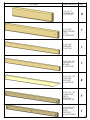
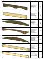
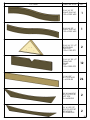
PICTURE
DESCRIPTION
2 X 4 X 17"
LADDER STEP
2-4-1700-LS
2 X 4 X 29"
REAR CENTER
POST
2-4-2900-RCP
2 X 4 X 47"
STRINGER
2-4-4700-S
2 X 4 X 47-1/2"
FRONT FACE
BOARD
2-4-4750-FFB
QTY.
4
1
1
1
2 X 4 X 47-1/2"
FORT SIDE
SUPPORT
2-4-4750-FSS
2
2 X 4 X 47-1/2"
PANEL AND
DECK
SUPPORT
2-4-4750-PDS
7
2 X 4 X 47-1/2"
ROCK WALL
ROPE
SUPPORT
2-4-4750-RWRS
1
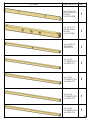
19
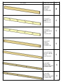
PICTURE
DESCRIPTION
QTY.
2 X 4 X 50"
END TARP
BOARD
2-4-5000-ETB
2
2 X 4 X 57"
LADDER LEFT
SIDE
2-4-5700-LLS
1
2 X 4 X 57"
LADDER RIGHT
SIDE
2-4-5700-LRS
1
2 X 4 X 58"
CROSS
MEMBER
2-4-5800-CM
1
2 X 4 X 73-3/4"
FRONT CENTER
POST
2-4-7375-FCP
1
2 X 4 X 83"
FRONT TARP
SUPPORT BOARD
2-4-8300-FTSB
1
2 X 4 X 83"
BACK TARP
SUPPORT BOARD
2-4-8300-BTSB
1
20
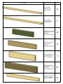
PICTURE
DESCRIPTION
QTY.
2 X 6 X 47-1/2"
ARCH FACE
BOARD
2-6-4750-AFB
1
2 X 6 X 47-1/2"
END SAND
BOX BOARD
2-6-4750-ESB
1
2 X 6 X 50"
ARCH ROCK
CENTER
SUPPORT
2-6-5000-ARWCS
1
2 X 6 X 53-1/2"
ROCK WALL
SUPPORT
2-6-5350-RWS
2
2 X 6 X 53-15/16"
ARCH ROCK
WALL SIDE
SUPPORT
2-6-5392-ARWSS
2
2 X 6 X 75"
LEFT SIDE SAND
BOARD
2-6-7500-LSSB
1
2 X 6 X 75"
RIGHT SIDE
SAND BOARD
2-6-7500-RSSB
1
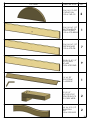
21
PICTURE
DESCRIPTION
QTY.
2 X 6 X 95-1/2"
END SAND BOX
BOARD
2-6-95500-ESB
1
4 X 4 X 47-1/2"
SWING BEAM
MOUNT
4-4-4750-SBM
1
4 X 4 X 89-1/2"
TRAP ARM
4-4-8950-TA
1
4 X 4 X 96"
CORNER POST1
4-4-9600-CP1
1
4 X 4 X 96"
CORNER POST2
4-4-9600-CP2
1
4 X 4 X 96"
CORNER POST3
4-4-9600-CP3
1
4 X 4 X 96"
CORNER POST4
4-4-9600-CP4
1
22
PICTURE
DESCRIPTION
QTY.
4 X 4 X 96"
SWING LEG
4-4-9600-SL
2
4 X 6 X 96"
SWING BEAM
4-4-9600-SB
1
5/4 X 3 X 11-1/2"
WINDOW PANEL
BOARD
125-3-1150-WPB
4
5/4 X 3 X 17-1/2"
TIC TAC TOE
MOUNT
125-3-1750-TTTM
2
5/4 X 4 X 18-1/2"
LADDER BACK
125-4-1850-LB
1
5/4 X 4 X 20"
WINDOW PANEL
BOARD
125-4-2000-WPB
4
5/4 X 4 X 40-1/2"
DECK SPACER
125-4-4050DS
2
23
PICTURE
DESCRIPTION
5/4 X 6 X 13-5/8"
OUTING SUN
125-6-1363-OS
QTY.
2
5/4 X 6 X 47-1/2"
BOTTOM ROCK
WALL BOARD
125-6-4750-BRWB
1
5/4 X 6 X 47-1/2"
DECK BOARD
125-6-4750-DB
7
5/4 X 6 X 47-1/2"
ROCK WALL
BOARD
125-6-4750-RWB
9
1 X 4 X 52"
ROOF PEAK
1-4-5200-RP
1
2 X 2 X 5"
WOOD ROOF
SPACER BLOCK
2-2-0500-WRSB
2
5/4 X 4 X 15-1/2"
WAVE SUN
RAY
125-4-1550-WSR
2
24
PICTURE
DESCRIPTION
QTY.
5/4 X 4 X 22"
WAVE SUN RAY
125-4-2200-WSR
1
5/4 X 4 X 25"
WAVE SUN RAY
125-4-2500-WSR
1
5/4 X 6 X 10-1/2"
ROOF PEAK
SUPPORT
125-6-1050-RPS
2
5/4 X 6 X 28-1/2"
DIAMOND
PANEL
SLAT
125-6-2850-DPS
12
1 X 6 X 52"
ROOF BOARD
1-6-5200-RB
26
2 X 6 X 44-5/16"
ROOF SUPPORT
LEFT SIDE
2-6-4438-RSLS
2
2 X 6 X 59-7/8"
ROOF SUPPORT
RIGHT SIDE
2-6-5988-RSRS
2
25
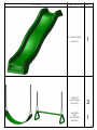
PICTURE
DESCRIPTION
8' WAVE SLIDE
03-0010
SWINGS
W/CHAINS
04-0002
TRAPEZE
BAR
W/CHAINS
04-0005
QTY.
1
2
1
26
PICTURE
DESCRIPTION
QTY.
SWING
PLATE
1
11-5002
CLIMBING
ROCKS
07-0008
A-FRAME
SWING LEG
BRACKET
11-5010
1700-1701,1702
10
1
1
INSTRUCTIONS EA.
HARDWARE
BOX
27
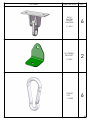
PICTURE
DESCRIPTION
IRON
DUCTILE
SWING
HANGERS
QTY.
6
11-4012
90 GREEN
BRACKET
11-5013
SPRING
CLIP
11-4003
2
6
28
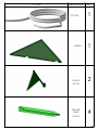
PICTURE
DESCRIPTION
10' ROPE
SCREEN
FLAG KIT
09-1014
GROUND
STAKE
07-0016
QTY.
1
1
2
4
29
PICTURE
DESCRIPTION
QTY.
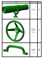
TELESCOPE
07-0001
1
STEERING
WHEEL
1
07-0004
SAFETY
HANDLE
2
07-0005
30
PICTURE
DESCRIPTION
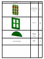
TIC TAC TOE
(UNASSEMBLED)
QTY.
1
07-0010
WINDOW
WINDOW
CROWN
2
1
07-0019
(NOT SHOWN)
NAME
PLATE
1
31
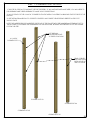
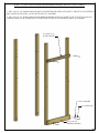
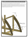
STEP 1: CORNER POST LAYOUT
1: THIS STEP IS CRITICAL TO BUILDING THE FORT PROPERLY. IF ANY MISTAKES ARE MADE HERE, YOU WILL NEED TO
DIS-ASSEMBLE AND THE RE-ASSEMBLE TO MAKE YOUR CORRECTIONS.
2: LAY OUT EACH OF THE 4 X 4 X 96" CORNER POST IN THE AREA YOU INTEND ON BUILDING THE FORT SIDE OF THE
PLAYSET.
3: USE THE DIAGRAM BELOW TO CORRECTLY IDENTIFY AND ORIENT THE NECESSARY DIRECTION THE POST
SHOULD FACE.
NOTE: THE LADDER SIDE IS CONSIDERED THE FRONT OF THE PLAYSET WITH THE SWINGBEAM EXTENDING OFF TO
THE LEFT SIDE. IF YOU PREFER THE SWINGBEAM ON THE RIGHT SIDE, REVERSE THE ORIENTATION OF THE CORNER
POST IN THIS STEP.
LEFT SIDE WILL
HAVE EXTRA HOLES
AT THESE LOCATIONS
4 X 4 X 96"
CORNER POST
REAR CORNER
POST WILL HAVE
EXTRA HOLES AT
THIS LOCATION
CORNER POST #3
CORNER POST #4
CORNER POST #2
CORNER POST #1
32
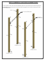
STEP 2: INSERTING T-NUTS INTO CORNER POSTS
1: USE A HAMMER TO SEAT THE T-NUTS AFTER INSERTING THEM INTO THE HOLES SHOWN IN THE DIAGRAM BELOW.
2: THE BARREL OF THE T-NUT SHOULD GO IN THE HOLE FIRST. HAMMER THE T-NUT UNTIL IS FLUSH/ALMOST FLUSH
TO THE CORNER POSTS.
T-NUT
NO T-NUTS IN THESE HOLES
NO T-NUTS
IN THESE HOLES
CORNER POST #3
CORNER POST #4
CORNER POST #2
CORNER POST #1
33
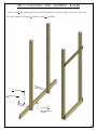
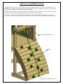
STEP 3: ATTACHING SANDBOX AND ROPE SUPPORT
1: THE 2 X 6 X 47-1/2" SANDBOX BOARD (WITH FOUR PRE-DRILLED HOLES) ATTACHES TO THE BOTTOM OF THE RIGHT
SIDE CORNER POSTS WITH 4-1/2" HEX BOLTS AND 5/16" WASHERS.
2: THE 2 X 4 X 47-1/2" ROPE SUPPORT (WITH THREE PRE-DRILLED HOLES) ATTACHES TO THE TOP SET OF HOLES ON
THE RIGHT SIDE OF THE CORNER POSTS, OFFSET HOLES UP, WITH 4-1/2" HEX BOLTS AND 5/16" WASHERS.
2 X 4 X 47-1/2"
ROPE SUPPORT
5/16" WASHER
4-1/2" HEX BOLT
2 X 6 X 47-1/2"
SANDBOX BOARD
34
STEP 4: ATTACHING END SANDBOX
BOARD
1
1: THE 2 X 6 X 95 " END SANDBOX BOARD (WITH SIX PRE-DRILLED HOLES) ATTACHES TO THE BOTTOM OF THE
2
1
5
LEFT SIDE CORNER POSTS WITH 4 " HEX BOLTS AND " WASHERS.
2
16
5
" WASHER
16
1
4 " HEX BOLT
2
1
2 X 6 X 95 "
2
END SANDBOX
BOARD
35
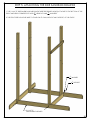
STEP 5: ATTACHING THE SIDE SANDBOX BOARDS
1: THE 2 X 6 X 75" SIDE SANDBOX BOARDS (WITH THREE PRE-DRILLED HOLES) ATTACHES TO THE BOTTOM OF THE
1
5
FRONT AND REAR CORNER POSTS WITH 4 " HEX BOLTS AND " WASHERS.
2
16
2: THE STRUCTURE SHOULD BE ABLE TO STAND ON ITS OWN, WITHOUT ANY SUPPORT, AT THIS STAGE.
5
" WASHER
16
1
4 " HEX BOLT
2
2 X 6 X 75"
SIDE SANDBOX BOARD
36
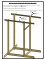
STEP 6: ATTACHING TARP SUPPORT BOARDS
1: THE 2 X 4 X 83" TARP SUPPORT BOARDS (WITH THE PRE-DRILLED HOLES) ATTACH TO THE TOP OF THE FRONT
5
1
AND REAR CORNER POSTS WITH 4 " HEX BOLTS AND " WASHERS.
2
16
2: OFFSET HOLES SHOULD BE POINTED DOWN ON BOTH BOARDS.
3: THE SHORTEST END FROM THE COUNTER-SUNK HOLES WILL POINT TOWARD THE SWING BEAM SIDE OF THE FORT.
5
" WASHER
16
1
4 " HEX BOLT
2
2 X 4 X 83"
TARP SUPPORT
BOARD
(OFFSET DOWN)
37
STEP 7: ATTACHING ARCH FACE BOARD AND DECK SUPPORT
1: THE 2 X 6 X 4712" ARCH FACE BOARD (WITH FOUR PRE-DRILLED HOLES) ATTACHES TO THE SET OF HOLES BELOW
THE TARP SUPPORT BOARD. ATTACH THE TOP ARCH FACE BOARD HOLES USING 4 12" HEX BOLTS AND 516" WASHERS
AND 3 12" LAG SCREWS AND 516" WASHERS THROUGH THE BOTTOM HOLES.
2: THE 2 X 4 X 47 12" DECK SUPPORT BOARDS (WITH TWO PRE-DRILLED HOLES) ATTACH TO THE SET OF HOLES ABOVE
THE SANDBOX BOARD AND THE GROUND SUPPORT BOARD ON THE INSIDE OF THE LEFT AND RIGHT SIDE OF THE
CORNER POSTS WITH 4 12" HEX BOLTS AND 516" WASHERS.
3: OFFSET HOLES SHOULD BE POINTED DOWN ON BOTH DECK SUPPORT BOARDS.
2 X 6 X 4712"
ARCH FACE BOARD
5
5
16"
WASHER
X 4 1 2"
HEX BOLT
16
5
5
16"
X 3 12"
LAG SCREW
5
16"
5
1
16 X 4 2"
16"
HEX BOLT
WASHER
WASHER
2 X 4 X 47 12"
DECK SUPPORT
(OFFSET DOWN)
FRONT OF
P
LAYSET
38
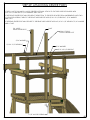
STEP 8: ATTACHING REAR PANEL SUPPORT BOARDS
1: THE 2 X 4 X 47 12" PANEL SUPPORT BOARDS (WITH TWO PRE-DRILLED HOLES) ATTACH TO THE SET OF HOLES
BELOW THE TARP SUPPORT BOARD ON THE REAR OF THE FORT WITH 516" X 4 12" HEX BOLTS AND 516" WASHERS.
2: HOLES SHOULD BE OFFSET DOWN.
5
16" X
4 12" HEX BOLT
5
16" WASHER
2 X 4 X 47 12"
REAR PANEL
SUPPORT BOARD
(OFFSET DOWN)
39
STEP 9: ATTACHING PANEL SUPPORTS AND SAFETY BOARD
1: THE 2 X 4 X 47-1/2" PANEL SUPPORT BOARDS SHOULD HAVE THE HOLES OFFSET UPWARDS.
USE 5/16" X 4-1/2" HEX BOLTS AND 5/16" WASHERS TO SECURE THE BOARDS TO THE CORNER POSTS.
2: PLACE THE TOP OF THE PANEL SUPPORT (USED AS SAFETY BOARD) 24" FROM THE BOTTOM OF THE 2 X 6 BOARD.
3: FASTEN THE SAFETY BOARD TO THE CORNER POSTS WITH 5/16" X 3-1/2" LAG SCREWS AND 5/16" WASHERS.
5/16" WASHER
5/16" X 4-1/2"
HEX BOLT
2 X 4 X 47-1/2"
PANEL BOARD
(OFFSET UP)
5/16" WASHER
5/16" X 3-1/2"
LAG SCREW
2 X 4 X 47-1/2"
PANEL BOARD
(SAFETY BOARD)
24"
40
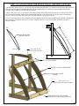
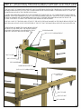
STEP 10: ATTACHING FORT SIDE SUPPORTS
1: LAY THE 2 X 4 X 47-1/2" FORT SIDE SUPPORTS ON A FLAT SURFACE WITH THE ANGLED ENDS ORIENTED THE WAY
THEY WILL BE INSTALLED ONTO THE FORT. PLACE A T-NUT IN THE PRE-DRILLED HOLE ON EACH END AND SECURE
WITH HAMMER.
2: THE 2 X 4 X 47-1/2" FORT SIDE SUPPORT (WITH ANGLED ENDS) ATTACHES TO THE HOLES ON THE END OF THE
END SANDBOX BOARD ON THE INSIDE WITH 2-1/2" HEX BOLTS AND 5/16" WASHERS. THE ANGLED END
SHOULD REST FLUSH AGAINST THE CORNER POSTS. SEE DETAIL A AND B.
3: ENSURE THAT THE TWO FORT SIDE SUPPORTS ARE ATTACHED PROPERLY TO THE END SANDBOX BOARD BEFORE
SECURING THEM TO THE CORNER POSTS. USE A 2-1/2" WOOD SCREW IN THE TOP HOLE OF THE SUPPORT, THEN USE A
3" WOOD SCREW IN THE BOTTOM HOLE OF THE SUPPORT. SEE DETAIL B.
2-1/2" WOOD SCREW
3" WOOD SCREW
DETAIL A
5/16" WASHER
DETAIL B
T-NUT
(INSTALL FIRST)
5/16" X 2-1/2" HEX BOLT
B
A
41
STEP 11: ATTACHING THE ROCK WALL SUPPORTS
1: LAY THE 2 X 6 X 53-1/2" ROCK WALL SUPPORTS ON A FLAT SURFACE WITH THE ANGLED ENDS ORIENTED THE WAY
THEY WILL BE INSTALLED ONTO THE PLAY SET. PLACE A T-NUT INTO THE PRE-DRILLED HOLE ON THE END AND
SECURE WITH A HAMMER.
2: LINE UP THE HOLE IN THE BOTTOM OF EACH 2 X 6 X 53-1/2" ROCK WALL SUPPORT TO THE HOLE ON THE END OF
EACH EXTENDED SANDBOX BOARD. ATTACH EACH ROCK WALL SUPPORT TO THE EXTENDED SANDBOX BOARD
WITH 2-1/2" HEX BOLTS AND 5/16" WASHERS. THE ANGLED END OF EACH ROCK WALL SUPPORT SHOULD REST FLUSH
AGAINST THE CORNER POST.
3: ENSURE THAT THE TWO ROCKWALL SUPPORTS ARE ATTACHED PROPERLY TO THE SANDBOX BOARDS BEFORE
SECURING THEM TO THE CORNER POSTS. USE A 2-1/2" WOOD SCREW IN THE TOP HOLE AND A 3" WOOD SCREW
IN THE BOTTOM HOLE OF THE ROCK WALL SUPPORT.
2-1/2" WOOD SCREW
3" WOOD SCREW
2 X 6 X 53-1/2"
ROCK WALL SUPPORT
T-NUT
5/16" WASHER
5/16" X 2-1/2" HEX BOLT
42
STEP 12: ATTACHING THE ARCH ROCK WALL SIDE SUPPORTS
1: MOUNT THE ARCH ROCK WALL SIDE SUPPORT ON TOP OF THE ROCK WALL SUPPORT, MAKE SURE THAT THE
TOP END OF THE ARCH ROCK WALL SIDE SUPPORT IS FLUSH WITH THE CORNER POST.
2: FIRST FASTEN THE 3" WOOD SCREW INTO THE ARCH ROCK WALL SIDE SUPPORT TOP HOLE INTO THE ROCK WALL
SUPPORT, MAKE SURE THAT THIS BOARD IS ALIGNED WITH THE ROCK WALL SUPPORT. SECOND FASTEN THE
3" WOOD SCREW INTO THE ARCH ROCK WALL SIDE SUPPORT BOTTOM HOLE TO THE ROCK WALL SUPPORT.
3: THIRD FASTEN THE 3" WOOD SCREW IN TO THE ROCK WALL SUPPORT TO THE ARCH ROCK WALL SUPPORT,
MAKE SURE BOTH BOARDS ARE TIGHT TOGETHER.
3" WOOD SCREW
(1)
2 X 6 X 54"
ARCH ROCK WALL
SIDE SUPPORT
3" WOOD SCREW
(3)
3" WOOD SCREW
(2)
43
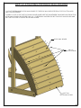
STEP 13: ATTACHING THE ROCK WALL CENTER SUPPORT
1: BEGIN WITH THE 5/4 X 6 X 47-1/2" ROCK WALL BOARD AND SECURE IT TO THE ARCH ROCK WALL SIDE SUPPORT
WITH TWO #8 X 2" WOOD SCREWS PER SIDE. THE ROUNDED EDGE OF THE ROCK WALL BOARD SHOULD BE
AGAINST THE CORNER POSTS BEFORE ATTACHING.
2: NEXT THE 5/4 X 6 X 47-1/2" BOTTOM ROCK WALL BOARD WITH ONE HOLE WILL MOUNT AT THE BOTTOM WITH
THE 7/8" HOLE TOWARDS THE BOTTOM. THIS BOARD WILL BE AT 44" FROM THE TOP ROCK WALL BOARD AND
FLUSH TO THE ROCK WALL SIDE SUPPORTS. SECURE WITH #8 X 2" WOOD SCREWS.
3: PLACE THE ARCH ROCK WALL CENTER SUPPORT BEHIND THE ROCK WALL BOARDS AND CENTER IT UNDER THE
SMALL HOLES. FASTEN THE ARCH ROCK WALL CENTER SUPPORT TO THE ROCK WALL BOARDS WITH #8 X 2"
WOOD SCREWS.
TOP
ARCH ROCK WALL
CENTER SUPPORT
BOTTOM
44"
5/4" X 6 X 47-1/2"
ROCK WALL BOARD
#8 X 2" WOOD SCREW
ARCH ROCK WALL SIDE SUPPORT
ARCH ROCK WALL CENTER
SUPPORT
5/4" X 6 X 47-1/2"
BOTTOM ROCK WALL BOARD
MAKE SURE ROCK WALL CENTER
SUPPORT IS NOT BLOCKING THIS HOLE
44
STEP 14: ATTACHING THE ROCK WALL BOARDS
1: MOUNT THE REMAINING ROCK WALL BOARDS TO THE ROCK WALL SUPPORTS FROM TOP TO BOTTOM WITH
#8 X 2" WOOD SCREWS.
2: WHEN YOU GET TO THE LAST ROCK WALL BOARD MAKE SURE THE GAP BETWEEN THIS BOARD AND THE BOTTOM
ROCK WALL BOARD IS NO BIGGER THAN 1/4". IF NECESSARY UNSCREW THE BOTTOM ROCK WALL BOARD AND
SHIFT THE TOP FLUSH TO THE LAST ROCK WALL BOARD.
ROCK WALL BOARD
#8 X 2"
WOOD SCREWS
BOTTOM
ROCK WALL BOARD
45
STEP 15: ATTACHING THE ROCKS
1: THE ROCKS SHOULD FOLLOW THE GENERAL STAGGERED LAYOUT SHOWN BELOW. HOWEVER, A DIFFERENT
CONFIGURATION CAN BE USED.
2: THE ROCKS INCLUDED WITH YOUR PLAYSET MAY VARY, IN ANY CASE, THE 1-1/4" PANHEAD SCREWS AND
WASHERS INCLUDED WITH THE ROCKS WILL BE USED TO ATTACH THE ROCKS.
1-1/4" PANHEAD
WOOD SCREW
DETAIL A
1/4" WASHER
ROCK
A
ROCKS
46
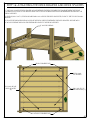
STEP 16: ATTACHING THE DECK BOARDS AND DECK SPACERS
1: THE 5/4 X 4 X 40-3/8" DECK SPACER MOUNTS BETWEN THE REAR CORNER POSTS AND BETWEEN THE FRONT
CORNER POSTS FLUSH TO THE EDGES. DRIVE THE 2" WOOD SCREWS THROUGH THE PREDRILLED HOLES INTO THE
DECK SUPPORTS.
2: SEVEN 5/4 X 6 X 47-1/2" DECK BOARDS WILL LAY ACROSS THE DECK SUPPORTS, FLUSH TO THE TOP ROCK WALL
BOARD.
3: SPACE DECK BOARDS EVENLY ACROSS THE DECK SUPPORTS BETWEEN THE DECK SPACERS. SECURE WITH
2" WOOD SCREWS THROUGH THE PREDRILLED HOLES TO THE DECK SUPPORTS.
2" WOOD SCREWS
REAR CORNER POSTS
ROCK WALL
TOP BOARD
5/4 X 4 X 40-3/8"
DECK SPACER
(2)
5/4 X 6 X 47-1/2"
DECK BOARDS (7)
FRONT CORNER POSTS
47
STEP 17:
ATTACHING THE DECK STRINGER
1: FIND THE 2 X 4 X 47-1/2" STRINGER WITHOUT HOLES.
2: PLACE THE STRINGER UNDEREATH THE CENTER OF THE DECK BOARDS (USE THE HOLE AT THE
CENTER AS A GUIDE) MAKE SURE THE END OF THE STRINGER IS FLUSH WITH THE DECK SPACER
ROUND EDGE.
3: ATTACH IT WITH 2" WOOD SCREWS TROUGH THE DECK BOARDS PREDRILLED HOLES AND IN TO THE STRINGER
BELOW.
2" WOOD SCREWS
STRINGER
FLUSH TO THE DECK SPACER
STRINGER
48
STEP 18: ATTACHING THE FRONT FACE BOARD
1: THE EDGE OF THE 2 X 4 X 47-1/2" FACE BOARD WILL BE FLUSH TO THE TOP OF THE DECK SPACER. SECURE
THE FACE BOARD TO THE CORNER POSTS WITH THREE 2-1/2" WOOD SCREWS PER SIDE.
2: INSTALL TWO 2-1/2" WOOD SCREWS THROUGH THE CENTER OF THE FACE BOARD INTO THE CENTER DECK
STRINGER AS SHOWN BELOW.
2 X 4 X 47-1/2"
FRONT FACE BOARD
2-1/2" WOOD SCREWS
DECK SPACER
FLUSH TO THE TOP OF THE DECK SPACER
STRINGER
2-1/2"
WOOD SCREWS
49
STEP 19: SWING BEAM PLATE
1: LAY THE SWING BEAM SUPPORT ON A FLAT SURFACE WITH THE THREE COUNTER SUNK CENTER HOLES FACING
THE GROUND, THE COUNTER SUNK HOLES ON THE ENDS MUST BE FACING TOWARDS YOU.
2: PLACE THE SWING BEAM PLATE ON TOP OF THE SWING BEAM SUPPORT, LINING UP PILOT HOLES.
2: FASTEN THE SWING BEAM PLATE TO THE SWING BEAM SUPPORT ON THE OUTSIDE HOLES USING 3/8" X 3-1/2"
CARRIAGE BOLTS, AND 3/8" WASHERS AND LOCK NUTS ON THE BOTTOM. PLACE GREEN BOLT COVERS OVER
EXPOSED THREADS AFTER SECURING.
3: LEAVE THE MIDDLE HOLE EMPTY, IT WILL BE USED LATER.
3/8" X 3-1/2" CARRIAGE BOLT
SWING BEAM PLATE
MIDDLE HOLE EMPTY
4 X 4 X 47-1/2"
SWING BEAM SUPPORT
3/8" WASHER
3/8" LOCK NUT
BOLT COVER
50
STEP 20: IRON DUCTILES
1: LINE UP THE HOLES OF THE IRON DUCTILES WITH THE HOLES IN THE SWING BEAM.
2: FASTEN THE IRON DUCTILES TO THE SWING BEAM USING 3/8" X 6-1/2" CARRIAGE BOLTS WITH TORQUE
WASHERS ON TOP OF THE SWING BEAM, AND 3/8" WASHERS AND LOCK NUTS ON THE BOTTOM. PLACE BOLT
COVERS OVER EXPOSED THREADS OFTER SECURING.
3: FASTEN IRON DUCTILES TO THE TRAP ARM IN THE SAME MANNER THAT YOU FASTENED THEM TO THE SWING
BEAM, USING 3/8' X 5" CARRIAGE BOLTS WITH TORQUE WASHERS ON TOP OF THE TRAP ARM, AND 3/8" LOCK
NUTS WITH 3/8" WASHERS ON THE BOTTOM. PLACE BOLT CAPS OVER ANY EXPOSED THREADS AFTER SECURING.
3/8" X 6-1/2" CARRIAGE BOLT
TORQUE WASHER
IRON DUCTILE
3/8" WASHER
3/8" LOCK NUT
4 X 6 X 96"
SWING BEAM
BOLT COVER
3/8" X 5" CARRIAGE BOLT
TORQUE WASHER
4 X 4 X 89-1/2"
TRAP ARM
IRON DUCTILE
3/8" WASHER
LOCK NUT
BOLT COVER
51
STEP 21: ATTACHING THE SWING BEAM SUPPORT AND TRAP ARM
1: THE 4 X 4 X 47-1/2" SWING BEAM SUPPORT HAS COUNTER-SUNK HOLES IN THE CENTER AND ON THE ENDS. INSTALL
THE SWING BEAM SUPPORT SO THAT THE COUNTER-SUNK HOLES ON EACH END OF THE BEAM FACE OUT, AND THE
COUNTER-SUNK HOLES AT THE CENTER FACE DOWN.
2: FASTEN THE SWING BEAM SUPPORT TO THE CORNER POSTS USING 3/8" X 6-1/2" CARRIAGE BOLTS WITH TORQUE
WASHERS. PLACE THE CARRIAGE BOLT INTO THE TORQUE WASHER, THEN INTO THE HOLE OF THE CORNER POST AND
SET WITH A HAMMER, USE 3/8" WASHERS AND LOCK NUTS TO SECURE THE SWING BEAM SUPPORT FROM THE
OUTSIDE. PLACE BOLT COVERS OVER THE EXPOSED THREADS AFTER SECURING.
3: THE 4 X 4 X 89-1/2" TRAP ARM WILL ATTACH TO THE UNIT IN THE SAME MANNER AS THE SWING BEAM SUPPORT. THE
TRAP ARM WILL MOUNT ON THE OPPOSITE SIDE OF THE FORT THAT THE SWING BEAM SUPPORT WAS MOUNTED ON.
THE HOLE ABOVE WHERE THE SWING BEAM SUPPORT
MOUNTS IS TO BE USED ONLY ON UNEVEN (UPHILL)
GROUND, IF INSTALLING ON A RELATIVELY LEVEL
SURFACE, THIS HOLE WILL NOT BE USED.
TORQUE WASHER
3/8" X 6-1/2" CARRIAGE BOLT
BOLT COVER
3/8" LOCK NUT
3/8" WASHER
SWING BEAM SUPPORT
3/8" X 6-1/2" CARRIAGE BOLT
4 X 4 X 89-1/2"
TRAP ARM
BOLT COVER
3/8" LOCK NUT
3/8" WASHER
52
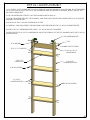
STEP 22: LADDER ASSEMBLY
1: LAY ONE 2 X 4 X 57" LADDER SIDE ON A FLAT SURFACE WITH THE CHANNELS FACING DOWN. PLACE THE BARREL
OF A T-NUT IN THE HOLE AT THE TOP OF THE LADDER SIDE AND SECURE WITH A HAMMER. REPEAT THIS STEP FOR
THE OTHER LADDER SIDE.
2: FLIP THE LADDER SIDE OVER SO THAT THE CHANNELS ARE FACING UP.
3: PLACE THE LADDER STEP INTO THE CHANNELS, AND THEN PLACE THE SECOND LADDER SIDE ON TOP, WITH THE
CHANNELS FACING DOWN.
4: NOW PLACE TWO 2" WOOD SCREWS IN EACH STEP.
5: CAREFULLY TURN THE LADDER OVER AND FINISH THE OTHER SIDE WITH TWO 2" WOOD SCREWS PER STEP.
6: INSTALL TWO 90
GREEN BRACKETS USING 1-1/2" BOLTS AND 5/16" WASHERS.
7: INSTALL THE 5/4" X 4 X 18-1/2" LADDER BACK ABOVE THE OPENING OF THE TOP CHANNELS WITH ONE 2" WOOD
SCREW PER SIDE.
90 GREEN BRACKET
5/16" WASHER
T-NUT
2" WOOD SCREW
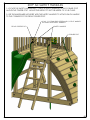
5/16" X 1-1/2" HEX BOLT
2 X 4 X 17"
LADDER STEP
5/4" X 4 X 18-1/2"
LADDER BACK
2 X 4 X 57"
LADDER SIDE RIGHT
2" WOOD SCREW
2 X 4 X 57"
LADDER SIDE LEFT
2" WOOD SCREW
53
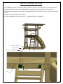
STEP 23: LADDER TO FORT
1: THE LADDER ATTACHES TO THE FRONT SIDE AT THE RIGHT, FLUSH TO THE INSIDE EDGE OF THE CORNER POST.
2: THE BOTTOM EDGE OF EACH 90 GREEN BRACKET SHOULD BE 3/4" FROM THE BOTTOM OF THE 2 X 4.
3: MAKE SURE THE LADDER IS LEVEL, USING THE LADDER BRACKETS AS A TEMPLATE, DRILL A 3/8" HOLE THROUGH
THE 2 X 4.
4: INSERT T-NUTS IN THE BACK OF THE HOLES.
5: ATTACH THE BRACKET TO THE 2 X 4 WITH 1-1/2" HEX BOLTS WITH 5/16" WASHERS.
A
90 GREEN BRACKET
5/16" WASHER
5/16" X 1-1/2" HEX BOLT
3/4"
2X4
54
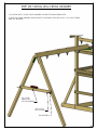
STEP 24: ATTACHING SWING LEGS TO BRACKET
1: PLACE THE 4 X 4 X 96" SWING LEGS FLUSH TO THE TOP OF THE SWING BRACKET.
2: USING THE SWING LEG BRACKET AS A TEMPLATE, DRILL 3/16" PILOT HOLES THROUGH EACH SWING LEG BRACKET
HOLE.
3: FASTEN THE SWING LEGS TO THE SWING LEG BRACKET WITH 3/8" X 3-1/2 LAG SCREWS AND 3/8" WASHERS.
SWING LEG BRACKET
3/8" X 3-1/2" LAG SCREW
3/8" WASHER
4 X 4 X 96" SWING LEG
SWING LEGS FLUSH
TO TOP OF SWING
LEG BRACKET
55
STEP 25: MOUNT SWING BEAM TO SWING BEAM LEGS
1: FASTEN THE SWING BEAM TO THE SWING BEAM BRACKET USING 3/8" X 6-1/2" CARRIAGE BOLTS WITH
TORQUE WASHERS ON TOP OF THE SWING BEAM, AND 3/8" LOCK NUTS WITH 3/8: WASHERS FROM UNDERNEATH.
2: USE A 3/8" X 3-1/2" LAG SCREW WITH 3/8" WASHER FOR THE HOLE IN THE CENTER OF THE SWING BEAM BRACKET.
3: PLACE A BOLT CAP OVER ANY EXPOSED THREADS.
3/8" X 6-1/2" CARRIAGE BOLT
TORQUE WASHER
3/8" WASHER
3/8" LOCK NUT
BOLT CAP
3/8" X 3-1/2"
LAG SCREW
56
STEP 26: MOUNT SWING BEAM TO FORT
AN EXTRA PERSON IS NEEDED FOR THIS STEP.
1: HAVE ONE PERSON WALK THE SWING BEAM OUT TO THE END ON THE FORT FROM INSIDE THE FORT
WHILE THE OTHER PERSON CARRIES THE LEGS.
2: LINE UP THE PILOT HOLE ON THE END OF THE SWING BEAM WITH THE MIDDLE HOLE ON THE SWING
BEAM PLATE.
3: FASTEN THE SWING BEAM TO THE SWING BEAM PLATE AND SWING BEAM SUPPORT USING A
3/8" X 9" CARRIAGE BOLT WITH TORQUE WASHER ON TOP AND A 3/8" LOCK NUT AND WASHER
ON THE BOTTOM. PLACE GREEN BOLT CAPS OVER EXPOSED THREADS AFTER SECURING.
4: FASTEN THE SWING BEAM TO THE SWING BEAM PLATE FROM
UNDERNEATH WITH A 3/8" X 3-1/2" LAG SCREW AND 3/8" WASHER.
3/8" X 3-1/2" LAG SCREW
3/8" X 9" CARRIAGE BOLT
SWING BEAM
TORQUE WASHER
3/8" WASHER
3/8" LOCK NUT
BOLT CAP
57
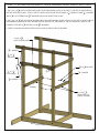
STEP 27: LEVEL SWING BEAM
1: PLACE THE LEVEL ON TOP OF THE SWING BEAM AND ADJUST THE BEAM LEGS IN OR OUT AS NEEDED TO
MAKE THE SWING BEAM LEVEL.
58
STEP 28: SWING LEG CROSS MEMBER
1: POSITION THE 2 X 4 X 58" CROSS MEMBER AGAINST THE SWING BEAM LEGS.
2: LEVEL THE CROSS MEMBER, AND SECURE TO THE SWING LEGS WITH 3/8" X 3-1/2" LAG SCREWS
AND 3/8" WASHERS.
2 X 4 X 58"
SWING LEG
CROSS MEMBER
3/8" X 3-1/2"
LAG SCREWS
3/8" WASHER
59
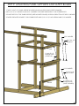
STEP 29: ATTACHING CENTER POSTS
1: THE 2 X 4 X 73-3/4" AND 2 X 4 X 29" CENTER POSTS WILL ATTACH TO THE TARP SUPPORT BOARDS WITH
5/16" X 2-1/2" HEX BOLTS, 5/16" WASHERS, AND T-NUTS.
2: THE FRONT CENTER POST WILL SECURE AT THE BOTTOM TO THE DECK SPACER, FROM UNDERNEATH, WITH TWO
2-1/2" WOOD SCREWS, THEN TO THE FRONT TARP SUPPORT WITH 5/16" X 2-1/2" HEX BOLT, 5/16" WASHER
AND T-NUT.
3: THE REAR CENTER POST WILL SECURE TO THE REAR TARP SUPPORT WITH A 5/16" X 2-1/2" HEX BOLT, 5/16" WASHER
AND A T-NUT.
2 X 4 X 29"
REAR CENTER POST
T-NUT
2 X 4 X 73-3/4"
FRONT CENTER POST
5/16" WASHER
5/16" X 2-1/2" HEX BOLT
5/16" WASHER
5/16" X 2-1/2" HEX BOLT
2-1/2" WOOD SCREWS
60
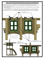
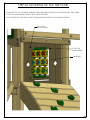
STEP 30: INSTALLING WINDOW SUPPORTS / WINDOWS
IN THIS STEP THE WOOD COMPONENTS TO ATTACH THE WINDOWS WILL BE INSTALLED ON THE INSIDE OF THE
FRONT OF THE PLAYSET. GO UP ON TOP OF THE FORT AND LOOK FOR THE FRONT OF THE PLAY SET.
1: ATTACH THE 5/4 X 4 X 20" VERTICAL WINDOW SUPPORTS NEXT TO THE FRONT CENTER POST IN BOTH SIDES
WITH 2" WOOD SCREWS.
2: ATTACH THE 5/4 X 4 X 20" VERTICAL WINDOW SUPPORTS NEXT TO THE CORNER POSTS IN BOTH SIDES WITH
2" WOOD SCREWS.
3: GO TO THE OUTSIDE FRONT OF THE PLAYSET AND INSTALL THE WINDOW WITH 1-1/2" WOOD SCREWS.
4: ATTACH THE 5/4 X 3 X 11-1/2" HORIZONTAL WINDOW SUPPORTS AT THE BOTTOM WITH 2" WOOD SCREWS.
5: ATTACH THE 5/4 X 3 X 11-1/2" HORIZONTAL WINDOW SUPPORTS AT THE TOP WITH 2" WOOD SCREWS.
5/4 X 4 X 20"
VERTICAL WINDOW SUPPORTS
1-1/2"
11-1/2"
11-1/2"
2" WOOD SCREWS
FRONT CENTER POST
WINDOWS
NOTE: THE 1" WIDE
FRAME SECTION IS TOP
5/4 X 3 X 11-1/2"
HORIZONTAL WINDOW SUPPORTS
OUTSIDE FRONT OF PLAYSET
FRONT OF PLAY SET
61
STEP 31: TARP BOARDS
1: THE TWO 2 X 4 X 50" TARP BOARDS WILL SECURE ON THE ENDS OF THE TARP SUPPORTS WITH TWO 2-1/2"
WOOD SCREWS PER SIDE
2 X 4 X 50"
TARP BOARD
TARP SUPPORTS
62
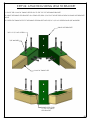
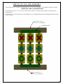
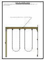
STEP 32: PANEL/WALL SLATS
1: BEGIN ON THE REAR SIDE OF THE FORT WITH THE TWO OUTER SLATS BOARDS. THEY ARE SPACED 3" FROM THE
CORNER POSTS. THE CUTOUT MUST BE FACING THE OPPOSITE DIRECTION.
2: PLACE THE INNER SLAT FLUSH TO THE OUTER SLAT. THE INNER SLAT CUTOUT MUST BE FACING THE OUTER SLAT
CUTOUT, CREATING A DIAMOND SHAPE OPENING IN BETWEEN.
3: ON THE SWING BEAM SIDE OF THE FORT START WITH THE TWO OUTER SLATS. THEY ARE SPACED 2-3/16" FROM
THE CORNER POSTS, THE CUTOUT MUST BE FACING THE OPPOSITE DIRECTION.
4: PLACE THE INNER SLAT FLUSH TO THE OUTER SLAT. THE INNER SLAT CUTOUT MUST BE FACING THE OUTER SLAT
CUTOUT, CREATING A DIAMOND SHAPE OPENING IN BETWEEN.
5: FOLLOWING THE SAME PATTERN, THE NEXT PAIR OF SLATS WILL BE SPACED 2" FROM THE FIRST PAIR.
ING
SW
BE
AM
SI D
2" WOOD SCREW
E
RE
AR
S
OU
TER
SL A
IDE
OF
FO
RT
TS
REAR SIDE OF FORT
SWING BEAM SIDE
3"
2-3/16"
2"
INNER SLAT
OUTER SLAT
INNER SLAT
OUTER SLAT
63
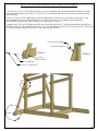
STEP 33: TIC TAC TOE ASSEMBLY
1: LOCATE THE TIC TAC TOE BOX. ASSEMBLE THE TIC TAC TOE ACCORDING TO THE INSTRUCTIONS IN THE BOX.
IGNORE STEPS 6 AND 7 IN THE INSTRUCTIONS.
2: LOCATE THE 5/4 X 3 X 17-1/2" TIC TAC TOE MOUNTS. DRILL A 1/8" HOLE IN EACH END OF THE MOUNT AS
SHOWN BELOW.
3: FASTEN THE TIC TAC TOE MOUNTS TO THE GREEN TIC TAC TOE BRACKETS WITH THE SCREWS PROVIDED IN THE
TIC TAC TOE BOX.
5/4 X 3 X 17-1/2"
TIC TAC TOE BOARD
GREEN BRACKET
5/4 X 3 X 18-1/4"
TIC TAC TOE BOARD
64
STEP 34: MOUNTING TIC TAC TOE PANEL
1: PLACE THE TIC TAC TOE PANEL ASSEMBLY FROM THE PREVIOUS STEP ONTO THE BACK WALL. THE LOWER
TIC TAC TOE MOUNT BOARD SHOULD BE 4" ABOVE THE DECK.
2: ATTACH EACH TIC TAC TOE MOUNT TO THE PANEL SALTS WITH #8 X 1-3/4 WOOD SCREWS.
#8 X 1-3/4"
WOOD SCREW
TIC TAC TOE
MOUNT BOARD
PANEL SLAT
65
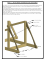
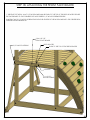
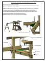
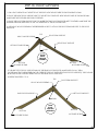
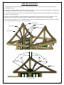
STEP 35: ROOF SUPPORTS
1: ON A FLAT SURFACE LAY THE LEFT ROOF SUPPORT WITH THE NOTCHED TIP END POINTING DOWN.
2: PLACE THE RIGHT ROOF SUPPORT NEXT TO THE LEFT ROOF SUPPORT WITH THE NOTCHED TIP FACING DOWN.
MAKE SURE THE TOP ENDS ARE FLUSH TOGETHER.
3: PLACE THE ROOF PEAK SUPPORT ON TOP WHERE THE TWO ROOF SUPPORTS MEET TOGETHER, MAKE SURE THE
ANGLED SURFACES ARE FLUSH TO THE TOP SURFACES OF THE ROOF SUPPORTS.
4: USE #8 X 2" WOOD SCREWS IN THE PREDRILLED HOLES TO ATTACH THE ROOF PEAK SUPPORTS TO THE ROOF
SUPPORTS.
#8 X 2" WOOD SCREWS
TOP
ROOF PEAK SUPPORT
RIGHT ROOF SUPPORT
LEFT ROOF SUPPORT
FLUSH
FRONT
ROOF
SUPPORT
ASSEMBLY
BOTTOM
BOTTOM
NOTCHED TIP END
NOTCHED TIP END
5: THE NEXT SET OF ROOF SUPPORTS WILL BE THE REAR ROOF SUPPORTS, MAKE SURE YOU LAY THEM
ON THE SAME FLAT SURFACE BELOW THE OTHER SET OF ROOF SUPPORTS (FRONT ROOF SUPPORTS). THEY SHOULD
BE PLACED IN THE OPPOSITE DIRECTION OF THE FRONT ROOF SUPPORTS.
6: REPEAT SUB-STEPS 1 TO 4.
TOP
#8 X 2" WOOD SCREWS
RIGHT ROOF SUPPORT
ROOF PEAK SUPPORT
LEFT ROOF SUPPORT
FLUSH
BOTTOM
NOTCHED TIP END
REAR
ROOF
SUPPORT
ASSEMBLY
BOTTOM
NOTCHED TIP END
66
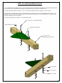
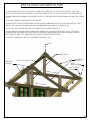
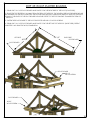
STEP 36: ROOF SUPPORTS TO FORT
1: GRAB THE FRONT SET OF ROOF SUPPORTS, AND PLACE THEM ON TOP OF THE TARP SUPPORT. THE LONG
ROOF SUPPORT (RIGHT ROOF SUPPORT) MUST BE MOUNTED ON TOP OF THE LONG SIDE OF THE TARP SUPPORT.
2: MAKE SURE FRONT ASSEMBLY IS CENTERED ON TOP OF THE TARP SUPPORT AND LEANING AGAINST THE CENTER
POST.
3: MOVE TO THE RIGHT SIDE (RIGHT ROOF SUPPORT).
4: DRIVE A #8 X 2" WOOD SCREW THROUGH THE FAR END PREDRILLED HOLE IN TO THE TARP SUPPORT, THEN
DRIVE A # 8 X 3" WOOD SCREW IN THE SECOND PREDRILLED HOLE NEXT TO THE FIRST HOLE.
5: MOVE TO THE OPPOSITE SIDE (LEFT ROOF SUPPORT) AND REPEAT SUB-STEP 4.
6: PUSH THE ROOF SUPPORT PEAK AGAINST THE CENTER POST AND SECURE WITH TWO #8 X 2-1/2" WOOD
SCREWS FROM THE CENTER POST INTO THE ROOF SUPPORTS, MAKE SURE ONE SCREW IS HOLDING THE LEFT
ROOF SUPPORT AND THE OTHER SCREW IS HOLDING THE RIGHT ROOF SUPPORT.
7: MOVE TO THE REAR OF THE FORT AND REPEAT SUB STEPS 1 TO 6.
PEAK
CENTER POSTS
LEFT ROOF
SUPPORT
RIGHT ROOF
SUPPORT
#8 X 2-1/2" WOOD SCREW
#8 X 2"
WOOD SCREW
#8 X 3" WOOD
SCREW
REAR OF
F RO N T O
F O RT
F F O RT
CENTER POSTS
67
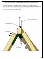
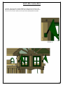
STEP 37: SUN AND PLASTIC SUN
1: PLACE THE WOOD SUN ON TOP OF THE TARP SUPPORT, MAKE SURE IT IS LEANING AGAINST THE CENTER POST,
CENTER IT WITH THE CENTER POST AND SECURE USING TWO #8 X 2" WOOD SCREWS.
2: REPEAT SUB-STEP 1 ON THE OPPOSITE SIDE.
3: PLACE THE PLASTIC SUN ON TOP OF THE WOOD SUN AND SECURE USING #8 X 1-1/4" WOOD SCREWS.
NOTE: PLASTIC SUN IS ONLY INSTALLED ON THE FRONT WOOD SUN
#8 X 2"
WOOD SCREW
CENTER POSTS
PLASTIC SUN
WOOD
SUN
REAR
OF F O
RT
PLASTIC SUN
FRONT OF FORT
NO PLASTIC SUN
#8 X 2"
WOOD SCREW
REAR OF FORT
68
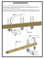
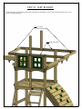
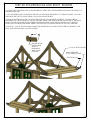
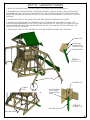
STEP 38: SUN RAYS
1: ALL THE SUN RAY PIECES GET INSTALLED TO THE INSIDE SURFACE OF THE ROOF SUPPORTS AND SUN PIECE
AT THE FRONT ONLY.
2: START FROM THE LEFT SIDE OF THE FORT PLACING THE 15-1/2" SUN RAY AT AN APPROXIMATE 60 ANGLE FROM
THE CENTER POST, SECURE WITH TWO #8 X 2" WOOD SCREWS .
3: PLACE THE SECOND 15-1/2" SUN RAY AT AN APPROXIMATE 35 ANGLE FROM THE CENTER POST, SECURE WITH
TWO #8 X 2" WOOD SCREWS.
4: MOVE TO THE OTHER SIDE OF THE CENTER POST (RIGHT SIDE OF FORT) AND PLACE THE 22" SUN RAY AT AN
APPROXIMATE 35 ANGLE FROM THE CENTER POST AND SECURE WITH TWO #8 X 2" WOOD SCREWS.
5: PLACE THE 25" SUN RAY NEXT TO THE PREVIOUS SUN RAY AT AN APPROXIMATE 60 ANGLE FROM THE CENTER
POST AND SECURE WITH TWO #8 X 2" WOOD SCREWS.
CENTER POST
15-1/2" SUN RAY
22" SUN RAY
#8 X 2"
WOOD SCREW
25" SUN RAY
60.00°
35.00°
35.00°
60.00°
15-1/2"
SUN RAY
22"
SUN RAY
25"
SUN RAY
FRONT OF FORT
69
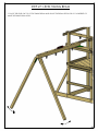
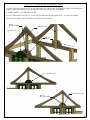
STEP 39: ROOF STARTER BOARDS
1: GRAB ONE 1 X 6 X 52" ROOF BOARD AND PLACE IT ON THE RIGHT SIDE OF THE ROOF (LONG SIDE).
2: PLACE THE TOP EDGE 56-1/4" AWAY FROM THE PEAK OF THE ROOF. THE HOLES IN THE ROOF BOARDS SHOULD
BE CENTERED ON THE ROOF SUPPORTS. THE ROOF BOARD SHOULD OVERLAP THE SIDES OF THE ROOF SUPPORTS
EQUALLY. THE HOLES OF THE ROOF BOARD SHOULD BE OFFSET TO THE TOP POINTING TOWARDS THE PEAK OF
THE ROOF.
3: FASTEN THE ROOF BOARD TO THE ROOF SUPPORTS WITH #8 X 2" WOOD SCREWS.
4: GRAB ONE 1 X 6 X 52" ROOF BOARD AND PLACE IT ON THE LEFT SIDE OF THE ROOF (SHORT SIDE). REPEAT
SUB STEPS 2 & 3 USING THE 40-3/4" DIMENSION.
LEFT SIDE
40-3/4"
56-1/4"
RIGHT SIDE
ROOF BOARD
ROOF BOARD
ROOF BOARD
#8 X 2"
WOOD SCREW
ROOF BOARD
#8 X 2"
WOOD SCREW
70
STEP 40: SPACER BLOCK AND ROOF ROARDS
1: LOCATE TWO SPACER BLOCKS AS SHOWN BELOW. VERIFY THAT THE SPACER BLOCKS HAVE THE CORRECT 4"
DIMENSION SHOWN.
2: YOU WILL NEED SOME CLAMPS FOR THIS STEP. WE USE HAND OPERATED 2-1/2" SPRING CLAMPS. YOU CAN
PURCHASE THIS TYPE OF CLAMP FROM YOUR LOCAL HOME CENTER.
3: PLACE A SPACER BLOCK ON TOP OF THE ROOF BOARD YOU INSTALLED IN STEP 39. YOU WILL NEED A
SPACER BLOCK ON EACH END OF THE ROOF BOARD. MAKE SURE THE SPACER BLOCK IS FLUSH TO THE FRONT
EDGE OF THE ROOF BOARD THAT IS ALREADY INSTALLED. NOW CLAMP THE SPACER BLOCK TO THE ROOF
BOARD THAT IS ALREADY INSTALLED. REPEAT THIS PROCESS FOR THE SPACER BLOCK ON THE OTHER SIDE.
4: PLACE A 1 X 6 X 52" ROOF BOARD AGAINST THE SPACER BLOCK. NOW ATTACH THE ROOF BOARD TO THE
ROOF SUPPORTS WITH #8 X 2" WOOD SCREWS.
4"
SPACER BLOCK
BOTTOM SIDE
VERIFY 4"
DIMENSION
WITH A TAPE
OR RULER
1 X 6 X 52" ROOF BOARD
HAND OPERATED
2-1/2" SPRING CLAMP
SPACER BLOCK
71
STEP 41: ROOF BOARDS
1: USING THE SAME SPACER BLOCK AND CLAMPS, REPEAT THE SAME PROCEDURE FROM STEP 40 FOR THE
REMAINING ROOF BOARDS UNTIL YOU GET ALMOST TO THE PEAK.
NOTE: IN THIS STEP, YOU WILL HAVE FOURTEEN ROOF BOARDS INSTALLED FOR THE RIGHT SIDE OF THE ROOF AND
TEN ROOF BOARDS INSTALLED FOR THE LEFT SIDE OF THE ROOF.
ROOF BOARD
SPACER BLOCK
HAND OPERATED
2-1/2" SPRING CLAMP
SIDE
RIGHT OF
OF RO
LEFT SID
OF ROOE
F
72
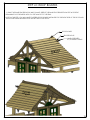
STEP 42: ROOF FINISHER BOARDS
NOTE: IN THIS STEP YOU WON'T NEED THE SPACER BLOCK OR CLAMP.
1: PLACE THE ROOF FINISHER BOARD ON TOP OF THE LAST ROOF BOARD FROM STEP 41, MAKE SURE THAT THE
ROOF FINISHER BOARD TOP EDGE IS FLUSH WITH THE ROOF PEAK SUPPORT TOP EDGE AND FLUSH TO BOTH
ENDS OF THE ROOF BOARD FROM THE PREVIOUS STEP.
2: FASTEN THE FINISHER BOARD TO THE ROOF SUPPORT WITH TWO #8 X 2" WOOD SCREWS.
3: MOVE TO THE LEFT SIDE OF THE ROOF AND PLACE THE ROOF FINISHER BOARD ON TOP OF THE LAST BOARD
FROM STEP 41, MAKE SURE THAT THE FINISHER ROOF BOARD TOP EDGE IS FLUSH WITH THE ROOF FINISHER BOARD
TOP EDGE FROM THE RIGHT SIDE AND FLUSH TO BOTH ENDS OF THE ROOF BOARD FROM STEP 41.
4: FASTEN THE FINISHER BOARD TO THE ROOF SUPPORT WITH TWO #8 X 2" WOOD SCREWS.
THIS FINISHER ROOF BOARD TOP EDGE
MUST BE FLUSH WITH THE
ROOF PEAK SUPPORT
1 X 6 X 52" ROOF BOARD
(FINISHER BOARD)
1 X 6 X 52" ROOF BOARD
(LAST FROM STEP 41)
SIDE
RIGHT OF
OF RO
1 X 6 X 52" ROOF BOARD
(FINISHER BOARD)
LEFT SI
O F R O DE
OF
73
STEP 43: ROOF PEAK
1: LOCATE THE 1 X 4 X 52" ROOF PEAK ASSEMBLY.
2: PLACE THE ROOF PEAK ON TOP OF THE LAST ROOF BOARDS.
3: USE A 1/8" DRILL BIT TO PREDRILL HOLES IN THE ROOF BOARDS USING THE ROOF PEAK HOLES AS A GUIDE.
4: ATTACH THE ROOF PEAK TO THE ROOF BOARDS WITH TWO #8 X 2" WOOD SCREWS PER SIDE.
1 X 4 X 52" ROOF PEAK ASSEMBLY
#8 X 2" WOOD SCREWS
74
STEP 44: SUNBURST MESH SCREEN
1: LOCATE THE SUNBURST MESH SCREEN. ATTACH THE MESH SCREEN BEHIND THE SUN
RAYS WITH #14 X 1-1/4" PAN HEAD SCREWS WITH 1/4" WASHERS.
2: THE NOTCHES IN THE SUNBURST MESH SCREEN WILL FIT AROUND THE TOPS OF THE
CORNER POSTS.
75
STEP 45: STEERING WHEEL
1: PLACE THE STEERING WHEEL INSERT INSIDE THE STEERING WHEEL.
2: USE THE HARDWARE INCLUDED WITH THE STEERING WHEEL TO MOUNT THE STEERING WHEEL TO THE END
OF THE SWING BEAM. DO NOT OVER-TIGHTEN THE LAG SCREW INTO THE STEERING WHEEL, OR IT WILL NOT
TURN.
3: PLACE THE STEERING WHEEL CAP OVER THE CENTER OF THE STEERING WHEEL.
STEERING WHEEL CAP
INCLUDED HARDWARE
STEERING WHEEL
STEERING WHEEL INSERT
76
STEP 46: INSTALLING THE SLIDE
1: PLACE THE SLIDE IN THE OPENING AT THE FRONT OF THE FORT. LAY THE SLIDE ON THE DECK WITH THE LIP
EXTENDING ONTO THE DECK.
2: ATTACH THE SLIDE TO THE DECK WITH 1-1/4" WOOD SCREWS. **DO NOT OVER TIGHTEN**
#8 X 1-1/4"
WOOD SCREW
SLIDE
77
STEP 47: CLIMBING ROPE
1: THREAD ONE END OF THE 10" ROPE THROUGH THE HOLE ABOVE THE ROCK WALL. TIE SECURE KNOT ON
THE INSIDE OF THE TOP PANEL BOARD. ADD KNOTS IN ROPE TO AID IN CLIMBING. SET KNOTS ACCORDING
TO YOUR CHILD'S NEEDS. 2-3 KNOTS SHOULD BE SUFFICIENT.
2: THREAD THE OTHER END OF THE ROPE THROUGH THE HOLE IN THE BOTTOM ROCK WALL BOARD. PULL THE
ROPE TIGHT AND TIE A SECURE KNOT BEHIND THE BOTTOM ROCK WALL BOARD.
3 : ATTEMPT TO WRAP THE ROPE AROUND YOUR HAND. IF THE ROPE WRAPS AROUND YOUR HAND IT IS
TOO LOOSE. UNTIE THE TOP KNOT AND RETIE THE ROPE UNTIL IT NO LONGER WRAPS AROUND YOUR HAND.
THE KNOT BEHIND THIS HOLE
ROPE
THE KNOT BEHIND THIS HOLE
78
STEP 48: FLAG KITS
1: INSTALL THE FLAG KITS IN THE DESIRED LOCATION ON YOUR PLAY SET.
THE RECOMMENDED LOCATION IS ON THE CORNER POSTS AT THE FRONT
OF THE FORT. ATTACH THE FLAG KITS WITH THE HARDWARE PROVIDED.
DETAIL A
A
79
STEP 49: NAME PLATE
1: ATTACH THE NAME PLATE TO THE MIDDLE OF THE SWING BEAM WITH TWO 1-1/4"
WOOD SCREWS.
ATTACH NAME PLATE HERE WITH TWO 1-1/4" WOOD SCREWS.
80
STEP 50: HANGING SWINGS
1: LOCATE TWO SWING BELTS WITH CHAINS ATTACHED.
2: SNAP A SPRING CLIP THROUGH THE SWING HANGER LOOP ON THE SWING BEAM.
3: SNAP A CHAIN ONTO EACH SPRING CLIP. ADJUST EACH SWING UP OR DOWN BY
CLIPPING ONTO HIGHER OR LOWER CHAIN LINKS.
4: LOCATE ONE TRAPEZE BAR WITH CHAINS ATTACHED.
5: SNAP A SPRING CLIP THROUGH THE SWING HANGER LOOP ON THE TRAPEZE ARM.
6: SNAP A CHAIN ONTO EACH SPRING CLIP. ADJUST THE TRAPEZE BAR UP OR DOWN BY
CLIPPING ONTO HIGHER OR LOWER CHAIN LINKS.
**WARNING: DO NOT HANG SWING BELTS FROM TRAPEZE ARM**
SWING BEAM
TRAPEZE ARM
A
TRAPEZE
BAR
WITH CHAINS
SWING BELT
WITH CHAINS
SWING BELT
WITH CHAINS
SWING HANGER LOOP
SPRING CLIP
CHAIN FROM SWING BELT
DETAIL A
SCALE 1 : 10
81
STEP 51: GROUND STAKES
1: PLACE THE GROUND STAKES ON THE OUTSIDE OF THE SWING LEGS AS SHOWN BELOW.
2: HAMMER EACH GROUND STAKE IN AT AN ANGLE SIMILAR TO WHAT IS SHOWN. USE CAUTION WHEN
HAMMERING SO THAT YOU DO NOT MAR THE WOOD. LEAVE THE TOP PORTION OF THE GROUND STAKE
ABOVE THE GROUND FAR ENOUGH SO THAT YOU CAN STILL GET THE SCREW INTO THE HOLE AT THE TOP OF
THE STAKE.
3: SECURE EACH STAKE TO THE SWING LEGS WITH THE SCREWS PROVIDED WITH THE STAKES.
4: HAMMER A GROUND STAKE ON THE INSIDE OF EACH CORNER POST NEAR THE ROCK WALL. USE
CAUTION WHEN HAMMERING SO THAT YOU DO NOT MAR THE WOOD. LEAVE THE TOP PORTION OF THE
GROUND STAKE ABOVE THE GROUND FAR ENOUGH SO THAT YOU CAN STILL GET THE SCREW INTO THE
HOLE AT THE TOP OF THE STAKE.
5: SECURE EACH STAKE TO THE CORNER POSTS WITH THE SCREWS PROVIDED WITH THE STAKES.
SWING LEG
SCREW THAT
COMES WITH
GROUND STAKE
GROUND STAKE
DETAIL A
SCALE 1 : 8
SWING LEGS
CORNER POST
CORNER
POSTS
A
WOOD SCREW
THAT COMES
WITH GROUND
STAKE
B
GROUND STAKE
DETAIL B
SCALE 1 : 8
GROUND STAKES
82
STEP 52: SAFETY HANDLES
1: LOCATE THE SAFETY HANDLE BAG. PLACE A SAFETY HANDLE ON THE CORNER POST
AND FRONT CENTER POST. ADJUST THE HEIGHT TO SUIT THE NEEDS OF YOUR CHILD.
2: USE THE HARDWARE INCLUDED WITH THE SAFETY HANDLES TO ATTACH EACH HANDLE
TO THE CORNER POST OR FRONT CENTER POST.
#14 X 1-1/4" PAN HEAD SCREW AND 1/4" FLAT WASHER
INCLUDED WITH SAFETY HANDLES.
FRONT CENTER POST
SAFETY HANDLES
CORNER POST
83