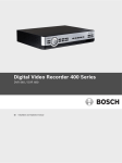
1
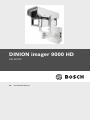
DINION imager 9000 HD
NAI-90022
en
Installation Manual
DINION imager 9000 HD
Table of Contents | en
3
Table of Contents
1
Safety
4
1.1
Safety precautions
4
1.2
Important safety instructions
4
1.3
Important notices
5
1.4
FCC & ICES compliance
8
1.5
FCC Information
1.6
CSA certification - Disclaimer
2
Planning
12
2.1
Pre-installation Checklist
14
3
Installation
16
3.1
Overview of Installation Steps
16
3.2
Select Tilt and Width of Illumination Beam
17
9
10
3.2.1
Changing the angle of IR LED tilt
18
3.2.2
Inserting the 3D diffuser
19
3.3
Unattach Junction Box
20
3.4
Mount the Junction Box
21
3.5
Route Wires and Attach Connectors
22
3.5.1
Input/Output Connections
23
3.6
Attach Camera to Junction Box
24
4
Camera Set-up
26
4.1
Rear controls
26
4.1.1
Accessing the control panel
26
4.1.2
Control panel
27
4.2
Camera positioning and field-of-view
28
4.2.1
Making Pan Adjustments
28
4.2.2
Making Tilt Adjustments
28
4.3
Using the install wizard
30
4.3.1
Adjustment procedure
30
Bosch Security Systems
Installation manual
AM18-Q0663 | 1.0 | 2013.09
4
en | Safety
DINION imager 9000 HD
1
Safety
1.1
Safety precautions
DANGER!
High risk: This symbol indicates an imminently hazardous
situation such as “Dangerous Voltage” inside the product.
If not avoided, this will result in an electrical shock, serious
bodily injury, or death.
WARNING!
Medium risk: Indicates a potentially hazardous situation.
If not avoided, this could result in minor or moderate bodily
injury.
CAUTION!
Low risk: Indicates a potentially hazardous situation.
If not avoided, this could result in property damage or risk of
damage to the unit.
NOTICE!
This symbol indicates information or a company policy that
relates directly or indirectly to the safety of personnel or
protection of property.
1.2
Important safety instructions
Read, follow, and retain all of the following safety instructions.
Heed all warnings on the unit and in the operating instructions
before operating the unit.
1.
Clean only with dry cloth.
2.
Do not block any ventilation openings. Install in
3.
Do not install near any heat sources such as radiators, heat
accordance with manufacturer’s instructions.
registers, stoves or other apparatus (including amplifiers)
that produce heat.
AM18-Q0663 | 1.0 | 2013.09
Installation manual
Bosch Security Systems
DINION imager 9000 HD
4.
Safety | en
5
Protect the power cord from being walked on or pinched
particularly at plugs, convenience receptacles, and the
power where they exit from the apparatus.
5.
Use only attachments/accessories specified by the
manufacturer.
6.
Refer all servicing to qualified service personnel. Servicing
is required when the apparatus has been damaged in a
way, such as power-supply cord or plug is damaged, liquid
has been spilled or objects have fallen into the apparatus,
does not operate normally, or has dropped. When
servicing, power shall be disconnected.
1.3
Important notices
Accessories - Do not place this unit on an
unstable stand, tripod, bracket, or mount. The
unit may fall, causing serious injury and/or
serious damage to the unit. Use only with the
cart, stand, tripod, bracket, or table specified by
the manufacturer. When a cart is used, use
caution and care when moving the cart/
apparatus combination to avoid injury from tipover. Quick stops, excessive force, or uneven
surfaces may cause the cart/unit combination to
overturn. Mount the unit per the manufacturer's
instructions.
All-pole power switch - Incorporate an all-pole power switch,
with a contact separation of at least 3 mm in each pole, into the
electrical installation of the building. If it is needed to open the
housing for servicing and/or other activities, use this all-pole
switch as the main disconnect device for switching off the
voltage to the unit.
Camera signal - Protect the cable with a primary protector if
the camera signal is beyond 140 feet, in accordance with
NEC800 (CEC Section 60).
Bosch Security Systems
Installation manual
AM18-Q0663 | 1.0 | 2013.09
6
en | Safety
DINION imager 9000 HD
CAUTION!
This product has been tested according to standard CIE/IEC
62471:2006 “Photobiological safety of lamps and lamp
systems” and found to meet Risk Group 2 for exposure limit
4.3.7 “Infrared radiation hazard exposure limits for the eye.”
For other hazard exposure limits, the product was found to be
exempt. Risk Group 2 is characterized in the standard as
“products generally do not pose a realistic optical hazard if
aversion responses limit the exposure duration or where
lengthy exposures are unrealistic.” Since there is no aversion
response for IR, avoid eye exposure. Risk Group 2 sources do
not pose an infrared radiation hazard for the eye within 10 s
at distances beyond 200 mm or 8 inches.
The Exposure Hazard Value for the product (ratio of the
Exposure level to the Exposure limit) is up to 10 at a test
distance of 200 mm (8 inches). The Hazard Distance
(distance beyond which the product falls into the exempt/
safe group) is at most 640 mm (25 inches). Note that typical
use cases are well beyond the Hazard Distance.
When servicing the unit, physically disconnect the power
supply to avoid possible IR exposure to the eyes. If physical
disconnection is not possible, use appropriate shielding to
block the LED panel or use eye protection with a transmission
of 10% or less at a wavelength of 850 nm.
Coax grounding:
–
Ground the cable system if connecting an outside cable
system to the unit.
–
Connect outdoor equipment to the unit's inputs only after
this unit has had its grounding plug connected to a
grounded outlet or its ground terminal is properly
connected to a ground source.
–
Disconnect the unit's input connectors from outdoor
equipment before disconnecting the grounding plug or
grounding terminal.
AM18-Q0663 | 1.0 | 2013.09
Installation manual
Bosch Security Systems
DINION imager 9000 HD
–
Safety | en
7
Follow proper safety precautions such as grounding for
any outdoor device connected to this unit.
U.S.A. models only - Section 810 of the National Electrical Code,
ANSI/NFPA No.70, provides information regarding proper
grounding of the mount and supporting structure, grounding of
the coax to a discharge unit, size of grounding conductors,
location of discharge unit, connection to grounding electrodes,
and requirements for the grounding electrode.
Disposal - Your Bosch product was developed
and manufactured with high-quality material and
components that can be recycled and reused.
This symbol means that electronic and electrical
appliances, which have reached the end of their
working life, must be collected and disposed of
separately from household waste material.
Separate collecting systems are usually in place
for disused electronic and electrical products.
Please dispose of these units at an
environmentally compatible recycling facility,
per European Directive 2002/96/EC.
Electronic Surveillance - This device is intended for use in
public areas only. U.S. federal law strictly prohibits
surreptitious recording of oral communications.
Environmental statement - Bosch has a strong commitment
towards the environment. This unit has been designed to
respect the environment as much as possible.
Fuse rating - For protection of the device, the branch circuit
protection must be secured with a maximum fuse rating of 16A.
This must be in accordance with NEC800 (CEC Section 60).
Moving - Disconnect the power before moving the unit. Move
the unit with care. Excessive force or shock may damage the
unit and the hard disk drives.
Outdoor signals - The installation for outdoor signals, especially
regarding clearance from power and lightning conductors and
transient protection, must be in accordance with NEC725 and
NEC800 (CEC Rule 16-224 and CEC Section 60).
Bosch Security Systems
Installation manual
AM18-Q0663 | 1.0 | 2013.09
8
en | Safety
DINION imager 9000 HD
Permanently connected equipment - Incorporate a readily
accessible disconnect device external to the equipment.
Pluggable equipment - Install the socket outlet near the
equipment so it is easily accessible.
Power resupply - If the unit is forced to power down due to
exceeding the specified operating temperatures, disconnect
the power cord, wait for at least 30 seconds, and then
reconnect the power cord.
Power lines - Do not locate the camera near overhead power
lines, power circuits, or electrical lights, nor where it may
contact such power lines, circuits, or lights.
SELV - All the input/output ports are Safety Extra Low Voltage
(SELV) circuits. SELV circuits should only be connected to
other SELV circuits.
Because the ISDN circuits are treated like telephone-network
voltage, avoid connecting the SELV circuit to the Telephone
Network Voltage (TNV) circuits.
Video loss - Video loss is inherent to digital video recording;
therefore, Bosch Security Systems cannot be held liable for any
damage that results from missing video information. To
minimize the risk of lost digital information, Bosch Security
Systems recommends multiple, redundant recording systems,
and a procedure to back up all analog and digital information.
1.4
FCC & ICES compliance
FCC Information (U.S.A. and Canada)
This equipment has been tested and found to comply with the
limits for a Class B digital device, pursuant to part 15 of the
FCC Rules. These limits are designed to provide reasonable
protection against harmful interference in a residential
installation. This equipment generates, uses, and can radiate
radio frequency energy and, if not installed and used in
accordance with the instructions, may cause harmful
interference to radio communications. However, there is no
guarantee that interference will not occur in a particular
installation. If this equipment does cause harmful interference
AM18-Q0663 | 1.0 | 2013.09
Installation manual
Bosch Security Systems
DINION imager 9000 HD
Safety | en
9
to radio or television reception, which can be determined by
turning the equipment off and on, the user is encouraged to try
to correct the interference by one or more of the following
measures:
–
reorient or relocate the receiving antenna;
–
increase the separation between the equipment and
receiver;
–
connect the equipment into an outlet on a circuit different
from that to which the receiver is connected;
–
consult the dealer or an experienced radio/TV technician
for help.
Intentional or unintentional modifications, not expressly
approved by the party responsible for compliance, shall not be
made. Any such modifications could void the user's authority to
operate the equipment. If necessary, the user should consult
the dealer or an experienced radio/television technician for
corrective action.
The user may find the following booklet, prepared by the
Federal Communications Commission, helpful: How to Identify
and Resolve Radio-TV Interference Problems. This booklet is
available from the U.S. Government Printing Office,
Washington, DC 20402, Stock No. 004-000-00345-4.
1.5
FCC Information
Informations FCC et ICES (modèles utilisés aux États-Unis et
au Canada uniquement)
Suite à différents tests, cet appareil s'est révélé conforme aux
exigences imposées aux appareils numériques de classe B, en
vertu de la section 15 du règlement de la Commission fédérale
des communications des États-Unis (FCC), et en vertu de la
norme ICES-003 d'Industrie Canada. Ces exigences visent à
fournir une protection raisonnable contre les interférences
nuisibles lorsque l'appareil est utilisé dans le cadre d'une
installation résidentielle. Cet appareil génère, utilise et émet
de l'énergie de radiofréquences et peut, en cas d'installation ou
d'utilisation non conforme aux instructions, engendrer des
Bosch Security Systems
Installation manual
AM18-Q0663 | 1.0 | 2013.09
10
en | Safety
DINION imager 9000 HD
interférences nuisibles au niveau des radiocommunications.
Toutefois, rien ne garantit l'absence d'interférences dans une
installation particulière. Il est possible de déterminer la
production d'interférences en mettant l'appareil
successivement hors et sous tension, tout en contrôlant la
réception radio ou télévision. L'utilisateur peut parvenir à
éliminer les interférences éventuelles en prenant une ou
plusieurs des mesures suivantes:
–
Modifier l'orientation ou l'emplacement de l'antenne
réceptrice;
–
Éloigner l'appareil du récepteur;
–
Brancher l'appareil sur une prise située sur un circuit
différent de celui du récepteur;
–
Consulter le revendeur ou un technicien qualifié en radio/
télévision pour obtenir de l'aide.
Toute modification apportée au produit, non expressément
approuvée par la partie responsable de l'appareil, est
strictement interdite. Une telle modification est susceptible
d'entraîner la révocation du droit d'utilisation de l'appareil. Au
besoin, l’utilisateur consultera son revendeur ou un technicien
qualifié en radio/télévision, qui procédera à une opération
corrective.
La brochure suivante, publiée par la Commission fédérale des
communications (FCC), peut s'avérer utile : How to Identify and
Resolve Radio-TV Interference Problems (Comment identifier et
résoudre les problèmes d’interférences de radio et de télévision).
Cette brochure est disponible auprès du U.S. Government
Printing Office, Washington, DC 20402, États-Unis, sous la
référence n° 004-000-00345-4.
1.6
CSA certification - Disclaimer
CSA has not tested the performance or reliability of the security
or signaling aspects of this product. CSA has only tested fire,
shock and/or casualty hazards as outlined in CSA's Standard(s)
for Safety for Closed Circuit Television Equipment, UL 2044. CSA
Certification does not cover the performance or reliability of
AM18-Q0663 | 1.0 | 2013.09
Installation manual
Bosch Security Systems
DINION imager 9000 HD
Safety | en
11
the security or signaling aspects of this product.
CSA MAKES NO REPRESENTATIONS, WARRANTIES, OR
CERTIFICATIONS WHATSOEVER REGARDING THE
PERFORMANCE OR RELIABILITY OF ANY SECURITY OR
SIGNALING RELATED FUNCTIONS OF THIS PRODUCT.
1.7
Bosch notices
Copyright
This manual is the intellectual property of Bosch Security
Systems and is protected by copyright. All rights reserved.
Trademarks
All hardware and software product names used in this
document are likely to be registered trademarks and must be
treated accordingly.
NOTE:
This manual has been compiled with great care and the
information it contains has been verified thoroughly. The text
was complete and correct at the time of printing. The ongoing
development of products means that the content of the user
guide can change without notice. Bosch Security Systems
accepts no liability for damage resulting directly or indirectly
from faults, incompleteness or discrepancies between the user
guide and the product described.
More information
For more information, please contact the nearest Bosch
Security Systems location or visit www.boschsecurity.com
Bosch Security Systems
Installation manual
AM18-Q0663 | 1.0 | 2013.09
12
2
en | Planning
DINION imager 9000 HD
Planning
This equipment should be unpacked and handled carefully. If an
item appears to have been damaged in shipment, notify the
shipper immediately.
Verify that all the parts listed in the Parts List below are
included. If any items are missing, notify your Bosch Security
Systems Sales or Customer Service Representative.
The original packing carton is the safest container in which to
transport the unit and must be used if returning the unit for
service. Save it for possible future use.
Parts Included with the Product
Quantity
1
1
1
1
1
3
2
Item
IR Imager camera
Cable-managed pan/tilt bracket
Junction box
Sunshield
3D Diffuser
Hex keys (1x 5 mm; 1x 2.5 mm; 1x 4 mm)
Screws for adjusting the LED tilt (1x 25 mm; 1x 31
1
1
1
1
mm)
Corner mount kit (optional)
Mast mount kit (optional)
Quick Install Guide (this booklet)
Product CD with complete User Manual
User-Supplied Parts
Quantity
4
4
2
Item
Lag bolts, 1/4-9 x 2 (M7-0.35 x 50) with 1/2 in. head
12 mm (1/2 in.) washers
20 mm (3/4 in.) NPS watertight pipe fittings OR
--
15 mm (1/2 in.) NPS watertight pipe fittings
Stranded wire (AWG 16 to 22) OR Solid wire (AWG
--
16 - 26)
Metal conduit (for protection of power cables and
--
input/output cables)
Mounting hardware (such as a corner mount adapter
or pole mount adapter, available separately from
Bosch)
AM18-Q0663 | 1.0 | 2013.09
Installation manual
Bosch Security Systems
DINION imager 9000 HD
Planning | en
13
Required Tools (User-supplied)
–
2.5 mm (0.1 in.) straight-blade screwdriver
–
Socket wrench; 14 mm (9/16 in.) socket
–
Drill; 5.5 mm (7/32 in.) drill bit
WARNING!
Important mounting instructions
This apparatus must be securely attached to the wall in
accordance with these installation instructions. Failure to
follow installation instructions may result in injury or death.
CAUTION!
Ensure that the selected location is protected from falling
objects, accidental contact with moving objects, and
unintentional interference from personnel. Follow all
applicable building codes.
CAUTION!
The camera is designed to be installed on static structures
using the specified mounting adapters. It should not be
installed in dynamic environments or on moving objects such
as vehicles, ships or elevators.
Select a suitable location that protects the camera from
accidental damage, tampering and environmental conditions
exceeding the specifications of the camera.
Follow these mounting guidelines:
1.
Locate the camera such that it cannot be easily interfered
with, either intentionally or accidentally.
2.
Select a smooth, flat mounting surface that can support
the combined weight of the camera and mounting
hardware under all expected conditions of vibration and
temperature. Recommended mounting height is at least
4 m (13 ft); however, optimal conditions will vary with the
specific installation environment.
Bosch Security Systems
Installation manual
AM18-Q0663 | 1.0 | 2013.09
14
en | Planning
2.1
DINION imager 9000 HD
Pre-installation Checklist
WARNING!
This installation must be made by a qualified service person
and must conform to all local codes.
WARNING!
CSA Certified / UL Listed CLASS 2 (or Certified PoE+ rated
42.5 VDC to 57 VDC, 600 mA, 34.20 W (max), for IP models)
power adapters must be used in order to comply with
electrical safety standards.
WARNING!
Power and I/O cabling must be routed separately inside
different permanently earthed metal conduits.
WARNING!
Install external interconnecting cables in accordance with
NEC, ANSI/NFPA70 (for US application) and Canadian
Electrical Code, Part I, CSA C22.1 (for CAN application), and
in accordance with local country codes for all other countries.
CSA Certified / UL Listed CLASS 2 power adapters must be
used in order to comply with electrical safety standards.
Branch circuit protection incorporating a 20 A, 2-pole Listed
Circuit Breaker or Branch Rated Fuses are required as part of
the building installation. A readily-accessible 2-pole
disconnect device with a contact separation of at least 3 mm
must be incorporated.
1.
Determine the location and distance for the junction box
based on its voltage and current consumption.
2.
Use only UL-listed liquid tight strain reliefs for conduits to
the junction box to ensure that water cannot enter the box.
You must use 3/4 in. (20 mm) NPS watertight conduits and
fittings.
AM18-Q0663 | 1.0 | 2013.09
Installation manual
Bosch Security Systems
DINION imager 9000 HD
3.
Planning | en
15
Route all rough wiring including: power, audio, ethernet,
and alarms I/O.
4.
Select the appropriate mounting kit to use depending on
the location of the camera. The camera is intended to be
mounted securely to a wall using the mounting holes in the
junction box.
Bosch Security Systems
Installation manual
AM18-Q0663 | 1.0 | 2013.09
16
en | Installation
3
DINION imager 9000 HD
Installation
CAUTION!
Installation must be made by qualified service personnel and
must conform to the National Electrical Code and all
applicable local codes.
WARNING!
IMPORTANT MOUNTING INSTRUCTIONS
The camera must be attached securely to the wall in
accordance with these installation instructions. Failure to
follow installation instructions may result in injury or death.
The camera has been evaluated for wall mounting, through
the mounting holes in the junction box, using the following
hardware secured into a 2 x 4 stud under 1/2 in. drywall:
–
Four (4) Lag bolts, 1/4-9 x 2 (M7-0.35 x 50) with 1/2 in.
head
–
Four (4) 12 mm (1/2 in.) flat washers
The camera has not been evaluated for safety requirements
using other mounting kits.
3.1
Overview of Installation Steps
Follow these steps in sequence to mount the camera to a wall:
1.
Select tilt and width of illumination beam.
2.
Unattach the junction box.
3.
Mount the junction box.
4.
Route wires and attach connectors.
5.
Attach camera to junction box.
AM18-Q0663 | 1.0 | 2013.09
Installation manual
Bosch Security Systems
DINION imager 9000 HD
3.2
Installation | en
17
Select Tilt and Width of Illumination Beam
Before mounting the camera decide the application:
–
As a general guideline, the IR LED tilt angle should be
raised above the axis of the camera to reduce
overexposure in the foreground.
–
Use the 31 mm screw for general area surveillance /
–
Use the 25 mm screw for other use cases such as
targets closer to the camera.
monitoring a perimeter. (The camera is delivered with
the 25 mm screw in place, so for this type of
application the screw does not have to be changed.)
–
The 3D diffuser is recommended for wide-field-of-view
applications.
–
With the 3D diffuser, the resulting beam angle is 42°
(H) x 20° (V) to cover all the horizontal field of view
(FOV) of the widest (focal length of 10 mm)
application.
–
Without the 3D diffuser, the beam angle is 10° (H) x
10° (V) which provides the longest distance detection
distance. (The camera is delivered with the diffuser in
place, so for this type of application it does not have
to be inserted.)
Bosch Security Systems
Installation manual
AM18-Q0663 | 1.0 | 2013.09
18
en | Installation
3.2.1
DINION imager 9000 HD
Changing the angle of IR LED tilt
NOTICE!
Do not discard the additional LED tilt set screw supplied. It
may be required to adjust the angle of LED tilt.
1.
Unscrew the current tilt screw located between the
camera window and the IR LED window at the front of the
camera.
Figure 3.1
2.
Slot for set screw for adjusting angle of LED tilt
Screw the selected screw as far as possible into the hole.
The screw must be tightened completely to obtain the
desired angle.
WARNING!
The LED Tilt Set screw must be inserted completely so that
the integrated O-ring makes a seal with the camera housing. If
the screw is not completely inserted, the water tightness of
the camera will be compromised.
AM18-Q0663 | 1.0 | 2013.09
Installation manual
Bosch Security Systems
DINION imager 9000 HD
3.2.2
Installation | en
19
Inserting the 3D diffuser
1.
Unscrew the four captive screws beneath the illuminator at
the front of the unit (item 2).
Figure 3.2
3D Diffuser
2.
Using the captive screws, remove the 3D diffuser holder.
3.
Insert the 3D diffuser into the slit in the gasket on the 3D
diffuser holder.
Ensure that the diffuser is inserted into the camera
housing with the sticker side facing the LED array. It is
important that the diffuser is oriented with the sticker side
surface facing the LED array or IR performance will be lost.
4.
Insert the diffuser and holder assembly securely into the
camera housing.
5.
Tighten the four captive screws to seal the unit.
Bosch Security Systems
Installation manual
AM18-Q0663 | 1.0 | 2013.09
20
en | Installation
3.3
DINION imager 9000 HD
Unattach Junction Box
Before mounting the junction box, remove it from the camera
assembly.
1.
Use an allen key to loosen the two screws and open the
2.
Loosen the slotted screws of the input/ output terminal
junction box.
block (7-pin) and the slotted screws of the power terminal
block (2-pins).
3.
Use two wrenches to remove the BNC connector from the
bracket.
4.
5.
Disconnect the Ethernet connection.
Compress the bottom hinge pin by pushing the pin lever
downward and rotating it behind the hinge pin stop.
Figure 3.3
6.
Camera Box Hinge Alignment
Push and hold the top hinge and remove the junction box.
AM18-Q0663 | 1.0 | 2013.09
Installation manual
Bosch Security Systems
DINION imager 9000 HD
3.4
Installation | en
21
Mount the Junction Box
Figure 3.4
1.
Interior of the Junction Box
Decide which holes in the junction box to use to insert the
cables: the holes in the bottom of the box, the holes in the
back of the box, or the holes in the side of the box.
2.
3.
Remove the seals from the holes you will be using.
Using the wall mount bracket as a template, mark the
mounting holes.
4.
5.
Drill pilot holes at each marked point.
Align the mounting holes of the wall mount bracket with
the holes drilled in the wall.
6.
Using a socket wrench and a 14 mm (9/16 in.) socket (not
supplied), screw the first 1/4-9 x 2 (M7-0.35 x 50) lag bolt
(not supplied) with 12 mm (1/2 in.) washer (not supplied)
into the stud.
7.
8.
Repeat step 8 to attach the three remaining lag bolts.
Attach the appropriate NPS watertight pipe fittings (not
supplied) to the bottom or back holes of the junction box
through which to run the cables.
Bosch Security Systems
Installation manual
AM18-Q0663 | 1.0 | 2013.09
22
en | Installation
DINION imager 9000 HD
NOTICE!
You must use the appropriate UL-listed / NPS watertight
conduits and fittings to ensure that water cannot enter the
junction box.
–
Use 20 mm (3/4 in.) NPS fittings for the holes on the
bottom and back of the box.
–
3.5
Use 15 mm (1/2 in.) NPS fittings for the side holes.
Route Wires and Attach Connectors
1.
Route all video, control, and alarm wires through the
conduit fitting to the junction box. These wires must be
routed through a permanently earthed metal conduit.
2.
Route the power lines (24 VAC / 12 VDC) through the
conduit fitting to the junction box. Use stranded wire
(AWG 16 to 22) or solid wire (AWG 16 to 26). These wires
must be routed through a permanently earthed metal
conduit.
3.
Cut and trim all wires with sufficient slack to reach their
connector terminals in the box, but not so long as to be
pinched (about 5 mm (0.2 in.) of insulation).
4.
Loosen the screws of the 2-pin terminal block and attach
the incoming power wires.
5.
Tighten the screws of the 2-pin terminal block.
6.
Loosen the slotted screws of the 7-pin input/ output
terminal block, attach the wires according to the pin
definition table and retighten the screws.
NOTICE!
For a DC supply the polarity is important. Incorrect polarity
does not damage the camera, but will not allow the camera to
switch on. If input voltage is not within the specified range or
has incorrect polarity (DC only), the voltage indicator (a
yellow LED in the front window) turns on to indicate this
condition.
7.
Connect the incoming Ethernet cable to the RJ45
connector supplied in the camera junction box.
AM18-Q0663 | 1.0 | 2013.09
Installation manual
Bosch Security Systems
DINION imager 9000 HD
3.5.1
Installation | en
23
Input/Output Connections
Figure 3.5
#
1
2
3
4
5
6
7
Label
NC
V1
V2
T1
T2
D1
D2
8 +
9 _
Bosch Security Systems
Terminal Block for Input/Output Connections
Description
Not connected
Alarm output 2
Alarm output 1
Audio output
Audio input
Alarm input 1
GND
Yellow
White
Gray
Brown
Orange
Black
+12 VDC / 24 VAC
GND DC / 24 VAC
Red
Green
Installation manual
Wire Color
AM18-Q0663 | 1.0 | 2013.09
24
en | Installation
3.6
DINION imager 9000 HD
Attach Camera to Junction Box
The bottom hinge pin of the camera arm has a stop to hold the
hinge open while attaching the arm to the junction box.
DANGER!
Serious injury or death can occur if the hinge pins of the
camera arm are not fully engaged (locked) to the junction
box. Use caution before releasing the camera arm.
1.
Compress the bottom hinge pin by pushing the pin lever
downward and rotating it behind the hinge pin stop.
Figure 3.6
2.
Camera Box Hinge Alignment
Open the top hinge by pushing and holding up the pin
lever.
NOTICE!
Both hinge pins must be fully compressed to open (unlock)
the hinges of the camera arm and before proceeding to step
3.
3.
While continuing to hold the top hinge pin, open and align
the top and bottom hinges of the camera arm to their
mating points on the junction box.
4.
Once you have aligned the hinges, release the top hinge
pin to engage its mating hinge on the junction box, and
AM18-Q0663 | 1.0 | 2013.09
Installation manual
Bosch Security Systems
DINION imager 9000 HD
Installation | en
25
then release the bottom hinge pin from the hinge pin stop
to lock the camera arm to the junction box.
5.
Put the input/output terminal block on the bracket and
tighten the two slotted screws.
6.
Put the power terminal block on the bracket and tighten
the two slotted screws.
7.
Reattach the network cable from the camera to the
connector in the junction box.
8.
Reattach the BNC connector from the camera to the
bracket in the junction box.
CAUTION!
–
The ITE is to be connected only to PoE networks without
routing to the outside plant.
–
The camera can accept power from the 12 VDC / 24 VAC
power input or from the Ethernet input. Ensure that the
camera receives power from only one source.
9.
Attach an Ethernet cable (Cat-5e or Cat-6; maximum
distance 100 m (328 ft) to the connector in the junction
box.
Bosch Security Systems
Installation manual
AM18-Q0663 | 1.0 | 2013.09
26
en | Camera Set-up
4
DINION imager 9000 HD
Camera Set-up
Configuration of the camera is carried out via the network using
a web browser. Use the browser to configure the camera
settings, including lens zoom/ focus and IR LED power
intensity.
To position the camera use the controls on the rear to start the
installation wizard on the CVBS service output.
4.1
Rear controls
4.1.1
Accessing the control panel
1.
Unscrew the four captive screws of the access panel on
the rear of the camera housing (item 1 in the figure).
Figure 4.1
2.
Rear camera housing with access panel
Open the access panel.
NOTICE!
Remember to tighten the captive screws on the panel when
you finish the adjustments to seal the unit.
AM18-Q0663 | 1.0 | 2013.09
Installation manual
Bosch Security Systems
DINION imager 9000 HD
4.1.2
Camera Set-up | en
27
Control panel
Controls and sockets are located behind the access panel at
the rear of the camera housing.
micro SD
Menu
Reset TV out
1. MicroSD card slot
Insert a microSD card into the slot.
2. Menu button
Use this button to start the field-of view installation wizard.
3. Reset button
Restores a previous version of the
firmware if uploading a new version
fails. With the power on, press and
hold the reset button for more than
10 seconds to restore the factory
defaults.
4. Service video
output
Bosch Security Systems
2.5 mm jack provides a CVBS signal
(for installation purposes only)
Installation manual
AM18-Q0663 | 1.0 | 2013.09
28
en | Camera Set-up
4.2
DINION imager 9000 HD
Camera positioning and field-of-view
To help position the camera and set the field-of-view:
1.
Connect a monitor to the 2.5 mm jack using the optional
monitor cable (S1460) which provides a CVBS signal (for
installation purposes only).
2.
Apply power to the camera.
3.
After power-up, wait a little (about 20 seconds).
4.
Press the Menu button. This enables the service video
analog output.
Follow the instructions in Section 4.3 Using the install wizard,
Page 30 to position the camera. While using the wizard, the pan
and tilt position can be adjusted as outlined below.
4.2.1
Making pan adjustments
1.
Using the 4 mm hex key, loosen the bolts at the base of the
U-bracket to make the necessary pan adjustments.
2.
When loosened, adjust the camera to the desired pan
angle.
3.
4.2.2
Tighten the bolt to secure in place.
Making tilt adjustments
1.
Using the 2.5 mm hex key, unscrew the round caps where
the bracket attaches to the camera housing to expose the
bolts for tilt adjustment.
2.
Using the 4 mm hex key, loosen the bolts.
3.
Make the necessary tilt adjustments.
4.
Tighten the bolts to secure the camera in place.
5.
Replace the round caps when you finish the adjustments.
AM18-Q0663 | 1.0 | 2013.09
Installation manual
Bosch Security Systems
DINION imager 9000 HD
Figure 4.2
Camera Set-up | en
29
Example orientation: Camera rotated 90 degrees left, pointing
up 44 degrees. From left: front view, side view, back view
Figure 4.3
Example orientation: Camera rotated 90 degrees right, point-
ing down 48 degrees. From left: front view, side view, back view
Bosch Security Systems
Installation manual
AM18-Q0663 | 1.0 | 2013.09
30
en | Camera Set-up
4.3
DINION imager 9000 HD
Using the install wizard
The Menu button on the control panel is used to access the
camera install wizard. When there is a choice in the wizard, the
options are selected by either a short press (less than 2 s) or a
long press (more than 2 s) of the button.
The wizard handles the following functions:
–
Lens identification
–
Image orientation
–
Zoom and focus adjustment conditions
–
Auto focus
–
Analog output
Run the wizard to select orientation and field-of-view (zoom).
Note:
The zoom and focus are adjusted again later via the web
browser. This optimizes picture sharpness in both bright and
low-level lighting.
4.3.1
Adjustment procedure
If you have set up the camera and pressed the Menu button as
described in Section 4.2 Camera positioning and field-of-view,
page 28 then you see the following on the monitor screen:
Lens type:
CONTINUE
<press short>
State:
180° ROTATE
<press long>
Focus Indicator: 0
Timeout: 300
–
The lens type is identified and shown on the screen.
–
The iris is opened to its maximum value.
AM18-Q0663 | 1.0 | 2013.09
Installation manual
Bosch Security Systems
DINION imager 9000 HD
1.
Camera Set-up | en
31
To rotate the image 180°, press and hold the Menu button
until the image flips.
2.
Briefly press the Menu button to open the automatic
motorized focus adjustment screen.
3.
Briefly press the Menu button to set the focus and zoom
defaults.
–
The progress is shown on the monitor.
–
When the initial focus adjustment is finished, position
the camera using the pan and tilt adjustments.
4.
Briefly press the Menu button to start the automatic
motorized focus adjustment.
5.
Briefly press the Menu button again and again to scroll
through the seven preset zoom positions.
–
The selection moves back when the last position is
reached.
6.
When you reach the desired zoom position, use a long
press of the Menu button to set the zoom position and to
re-focus.
7.
If the camera is not correctly focussed, press the Menu
button for a longer time to restart the wizard.
If the camera is correctly focussed, press the Menu button
for a short time to change the analog output.
8.
Briefly press the Menu button again and again to select
NTSC or PAL with the appropriate aspect ratio for your
display, or to swich the analog output OFF (default).
9.
When the selection is made, use a long press of the Menu
button to save the results.
–
The zoom and focus position is stored.
–
The iris is set to its original value.
–
The video service output is disabled.
–
The BNC video output is set to its selected state.
Note:
The wizard automatically disappears if not used for a whle.
Bosch Security Systems
Installation manual
AM18-Q0663 | 1.0 | 2013.09
Bosch Security Systems
www.boschsecurity.com
© Bosch Security Systems, 2013