1
USER'S MANUAL
May be covered by one or more of the following: U.S. Patents #4538297, 4647876, 4696044, 4745309, 4881047, 4893099, 5124657, 5263091,
5268527, 5319713, 5333201, 5402498, 5493617 and 5638452. Other patents pending. Foreign patents pending.
Your Intellifex® Online has been tested and complies with the following Standards and
Directives as set forth by the European Union:
Council Directive(s):
89/336/EEC
Electromagnetic Compatibility
Standard(s):
EN55013, EN50082-1
This means that this product has been designed to meet stringent guidelines on how much
RF energy it can emit, and that it should be immune from other sources of interference
when properly used. Improper use of this equipment could result in increased RF emissions, which may or may not interfere with other electronic products.
To insure against this possibility, always use good shielded cables for all audio input and
output connections. Also, bundle audio cables separately from the AC power cables. These
steps will help insure compliance with the Directive(s).
For more information about other Rocktron products, please see your local dealer or one of
our importers closest to you (listed on the enclosed warranty sheet).
Copyright ©1997 Rocktron Corporation.
All rights reserved.
Contents
1. Introduction ................................................................................................................. 1
2. Quick Setup ................................................................................................................. 2
3. Front Panel .................................................................................................................. 3
4. Rear Panel ................................................................................................................... 5
5. Connections ................................................................................................................ 7
6. Principle of Operation ............................................................................................... 10
A. MIXER SECTION ........................................................................................................... 10
B. REVERB SECTION ....................................................................................................... 12
C. DELAY SECTION .......................................................................................................... 14
D. DUCKER SECTION ...................................................................................................... 16
E. PITCH CHANGE SECTION ........................................................................................... 17
PITCH SHIFT ..................................................................................................................... 18
F. HUSH® SECTION .......................................................................................................... 20
7. Configurations .......................................................................................................... 21
A. HUSH/CHORUS/DELAY/REVERB Configuration ...........................................................
HUSH/CHORUS/DELAY/REVERB Parameters .................................................................
B . HUSH/REVERB Configuration ......................................................................................
C. HUSH/DELAY/DUCKER Configuration ..........................................................................
D. HUSH/8 VOICE CHORUS/DELAY Configuration ...........................................................
E. HUSH/PITCH SHIFT/DELAY Configuration ....................................................................
F. HUSH/PITCH SHIFT/DELAY/REVERB Configuration ......................................................
22
23
24
26
29
31
33
8. Operating the Intellifex ............................................................................................. 35
A. Recalling a stored Intellifex Online preset ....................................................................... 35
B. Changing preset parameters ......................................................................................... 36
C. Storing modified parameter values ................................................................................ 37
D. Editing a preset title ....................................................................................................... 39
E. Selecting a "Power On" preset ...................................................................................... 40
9. MIDI Operation .......................................................................................................... 41
A. MIDI Controller Assignment ............................................................................................
B. MIDI Program Mapping ..................................................................................................
C. MIDI Channel .................................................................................................................
D. MIDI Dump/Load ............................................................................................................
E. Factory Restore .............................................................................................................
41
44
46
47
53
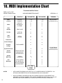
10. MIDI Implementation Chart ..................................................................................... 54
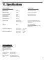
11. Specifications .......................................................................................................... 55
1. Introduction
Congratulations on your purchase of the Rocktron Intellifex ® Online!
The Intellifex Online features presets created and uploaded by Rocktron users from all
over the world to Rocktron's World Wide Web site. These presets can be easily updated from
the "Patch Bay" at Rocktron's web page. In addition, you can also upload your own custom
presets to share with other online users. For instructions on downloading and uploading
Intellifex presets, please visit our web site at "http://www.rocktron.com" and click "Patch
Bay".
The Intellifex Online is a 24-bit digital effects processor utilizing three individual 16-bit
converters and Sigma-Delta A/D conversion, achieving a 64x oversampling rate and better than
100dB dynamic range. It is totally programmable and allows for complete MIDI control. The
unit features pitch shifting, 8-voice stereo chorusing effects, digital delay effects (including 2tap, stereo and ping ponging effects), unsurpassed digital reverb quality and highly flexible
configuration programming—allowing for simultaneous operation of up to 5 effects plus complete mixing capabilities. The unit also offers a fully digital implementation of patented HUSH®
noise reduction at the unit’s input, along with delay and reverb ducking capabilities.
This user's manual will detail the various features and functions of the Intellifex Online.
After reading it, please keep it for future reference.
What makes the Intellifex Online Unique?
Super quiet operation due to use of digital HUSH® and high quality 16-bit converters.
High purity sound due to the use of a 64X oversampling A/D converter, which
samples the signal 64 times as often as a conventional converter, and also due to
the use of a separate dual D/A converter. Most "bargain" digital effects units use a
single converter multiplexed 3 ways, for decidedly higher distortion and lower
dynamic range.
24-Bit processing and memory circuits to maintain maximum dynamic range.
Ability to store up to 8 unique MIDI controller patches with each preset.
Very high quality effects algorithms.
Highly stereo effects with panning available on almost all signals.
8 voice chorusing with an enormous number of parameters for the richest sounding
chorus ever.
High quality 4 voice pitch shifting over 3 full octaves.
2-voice pitch shifting or 4-voice chorusing offered simultaneously with HUSH,
delay and reverb.
Programming via knobs instead of push buttons.
Easy to read, wide viewing angle display.
1
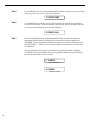
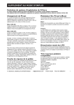
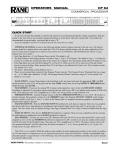
2. Quick Setup
Rcalling a Stored Intellifex Online Preset
Storing Modified Parameter Values
STEP 1
STEP 1
To recall a stored Intellifex Online preset, first turn the PRESET control
to the desired preset number you wish to recall. The display will alternate
between the preset number/title selected and:
STORE TO PRESET
PRESS RECALL FOR
STEP2
To call up the preset you have selected, press the RECALL button. The
display will now show only the new preset number/title.
STEP 2
14 PRESET TITLE
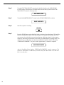
Changing Preset Parameters
STEP 1
To store modified parameter values, press the STORE button while
viewing a parameter or effect title to begin the store procedure. The
Intellifex Online will alternate displaying the current preset number/title
and:
Turn the PRESET control to select the desired preset number to store
the new parameter values into (if the new values are to be stored into
the current preset location, this step is not necessary). User presets
may be stored in preset locations 1-80. Presets 81-160 are factory
presets and cannot be copied over. The Intellifex Online will now
alternate displaying the new preset number/title and:
STORE TO PRESET
The parameter menu for each effect can be called up via the FUNCTION
SELECT control. Turn this control to the effect to be changed.
STEP 3
**** REVERB ****
Now press the STORE button a second time to store the modified
values into the selected preset location. The Intellifex Online will display
"STORED" briefly before displaying the new preset number/title.
STORED
STEP 2
Turn the PARAMETER SELECT control to select which parameter select
the parameter to be modified.
REV DECAY
STEP 3
NOTE 1
If it is not desired to copy the title from the original preset, turn either
the PRESET or FUNCTION SELECT control to exit the store procedure.
NOTE 2
If a modified preset is edited without completing the store procedure (i.e.
"STORED" displayed at least one time), all edited parameter values will
be lost and the preset will revert to its original condition the next time it is
recalled. When saving altered parameters, always make sure the
Intellifex Online flashes "STORED" at least once before exiting the
preset to ensure that the desired modifications were stored into
memory.
59
32
The COMPARE button may be used to compare the stored value to the
new one.
REV DECAY
2
After the modified parameters have been stored into a new preset
location, the Intellifex Online will display "COPY TITLE TOO?". This
occurs only when a new preset location is selected to store the modified
parameters into, and allows for the title from the original preset to be
copied to the new preset location as well. To copy the title, press the
STORE button a third time. The display will again flash "STORED".
Use the PARAMETER ADJUST control to modify the parameter value.
The LED above the STORE button lights to indicate that a parameter
value has been modified from the stored preset.
REV DECAY
STEP 4
STEP 4
59
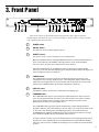
3. Front Panel
Some of the controls on the Intellifex Online front panel have more than one function,
dependent upon what mode the unit is currently operating in. Please read this section to become
better aquainted with these functions.
1
POWER switch
2
RECALL button:
This button is used to recall the displayed preset.
3
PRESET control:
The function of this control is dependent on the CONFIG button.
When the CONFIG LED is off, turning the PRESET control will cause the Intellifex Online to
exit its current function. The PRESET control may then be used to scroll through the
successive factory and user presets and titles stored in its memory.
When the CONFIG LED is on, the PRESET control is again used to scroll through the
successive presets, but instead of displaying preset titles the Intellifex Online will display the
effect configuration stored for each preset.
4
CONFIG button:
The CONFIG button is used to toggle between displaying either the preset title or the
configuration of the currently displayed preset. The configuration display indicates both
which effects the displayed preset executes and the order in which they are executed. The
LED above the CONFIG button is lit when the configuration is displayed.
5
DISPLAY panel:
The DISPLAY panel is a 16 character, vacuum fluorescent display type.
6
COMPARE button:
The COMPARE button may be used to compare a modified parameter value to its stored
value. (If comparing an altered value to the stored value and the stored value is currently
being viewed, turning a knob or pressing a button that changes the parameter value
displayed will cancel the previous modified value.)
The COMPARE button may also be used to simultaneously compare multiple modified
parameters under the same effect heading (i.e. Reverb, Mixer, etc.) to the stored values. To do
so, turn to the effect heading where the modified parameters are located and press the
COMPARE button. When the STORE LED is off, the stored parameter values are currently
active. When the STORE LED is lit, the modifed values are active.
If a knob is turned or a button is pressed which changes the effect heading when the stored
parameters are active (STORE LED off), any modified parameter values under that heading
will be lost. This is also true if a MIDI control change is received while the stored parameters
are active.
3
7
PARAMETER ADJUST control:
This control is used to adjust the displayed parameter value. When the parameter is changed
from its original value, the LED above the STORE button will light until either (a) the new
value is stored, (b) a new preset is selected or (c) the parameter is returned to its original
value.
8
STORE button:
This button is used to store values into the Intellifex Online memory when modified. See
Chapter 8, section C, "Storing Modified Parameters" for more information.
9
PARAMETER SELECT control:
When monitoring parameter values, this control will scroll through the available parameters
under the current effect heading.
In the "TITLE EDlT" function, this control will scroll through the available characters in the
title that may be edited.
10
FUNCTION SELECT control:
This control allows access to each function of the Intellifex Online. Depending on which
configuration the current preset is built upon, these functions may include:
Preset Select
Mixer Parameters
HUSH Parameters
Chorus Parameters
Pitch Shift Parameters
Delay Parameters
Factory Restore
4
Reverb Parameters
Title Edit
MIDI Controller Mapping
MIDI Program Mapping
MIDI Channel
Ducker Parameters
MIDI Dump/Load
11
BYPASS button:
When pressed, the LED is lit and all effects are bypassed.
12
INPUT LEVEL meter:
These LEDs provide visual indication of the peak level of the input signal. For the optimal
signal-to-noise ratio, it is best to adjust the input level so that the last LED (0dB) is rarely lit.
This will guard against the possibility of overdriving the unit.
13
INPUT LEVEL control:
This control adjusts the unit's gain to match the signal level at the input of the Intellifex
Online. The gain can be adjusted from -12dB to +12dB. Use the INPUT LEVEL meter to
determine the setting of this control.
14
CLIP L.E.D.:
This L.E.D. is part of the output section and, when lit, indicates that the final analog output is
being overdriven because the Effects Level, Direct level, and Output Level control are set too
high. If this occurs, reduce these levels until this L.E.D. does not light.
15
OUTPUT LEVEL control:
This control is used to adjust the output level of the unit and may be adjusted from zero
signal to a small amount of gain.
16
REFERENCE LEVEL switch:
This switch determines the output range of the unit and may be set at either -10dB or +4dB.
When using professional studio equipment providing a nominal input level of +4dB, it is
recommended that the +4 setting on the Intellifex Online be used for best results. If
connecting the Intellifex Online to a high sensitivity input, such as the input to a guitar amp,
the -10 setting should be used.
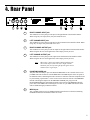
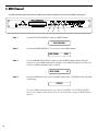
4. Rear Panel
1
RIGHT CHANNEL INPUT jack:
This standard 1/4" mono jack provides input to the right channel of the Intellifex Online.
When using only one input (mono), this jack should be used.
2
LEFT CHANNEL INPUT jack:
This standard 1/4" mono jack provides input to the left channel of the Intellifex Online. When
using only one input, this jack should not be used.
3
RIGHT CHANNEL OUTPUT jack:
This standard 1/4" mono jack provides an output for the right channel of the Intellifex Online.
When using the unit in a mono application, either output jack may be used.
4
LEFT CHANNEL OUTPUT jack:
This standard 1/4" mono jack provides output for the left channel of the Intellifex Online.
When using the unit in a mono application, either output jack may be used.
Note:
When using a mono input (Right Channel INPUT jack)
and a mono output (either the Left or Right Channel
OUTPUT jack), the left and right effected signals will be
summed at the single output.
5
PHANTOM POWER jack:
This jack offers the ability to power the Rocktron MIDI Mate™ Foot Controller from a seven
pin MIDI cable which connects from the MIDI Mate to the MIDI IN jack on the rear panel of
the Intellifex Online, eliminating the need to find an AC outlet near where the footpedal would
be placed during a performance—or the need to run an extension cord out to the MIDI Mate.
Instead of inserting the adaptor into the MIDI Mate POWER jack, plug it into the
PHANTOM POWER jack on the Intellifex Online. This will power the MIDI Mate through
pins 6 and 7 of the MIDI cable connecting the two units. A 7-pin MIDI cable must be used
and is available through your Rocktron dealer.
6
MIDI IN jack:
This 7-pin DIN connector receives MIDI information from the device which is transmitting
the MIDI commands for the Intellifex Online to execute.
5
7
MIDI OUT/THRU jack:
This standard 5-pin DIN connector passes on the MIDI information that is received at the
MIDI IN jack to other MlDI-compatible devices via a MIDI cable. It also outputs MIDI data
when performing a memory dump.
Note:
8
6
Inherently in MIDI there is a limit to the number of devices which can be chained
together (series connected). With more than three devices, a slight distortion of
the MIDI signal can occur (due to signal degradation) which can cause an error
in MIDI signal transmission. Should this problem arise, a MIDI box can be used
which connects directly to the MIDI device which transmits MIDI information and
has multiple connectors for the multiple devices receiving MIDI. MIDI cables
should not exceed 50 feet (15 meters) in length.
POWER jack:
This jack accepts power from the 9VAC/1500mA adaptor supplied with the unit. For more
information on the power supply see the Power Requirements section on page 2.
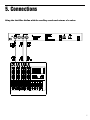
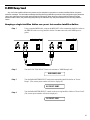
5. Connections
Using the Intellifex Online with the auxiliary sends and returns of a mixer
7
Using the Intellifex Online with a keyboard and a mixer
8
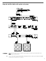
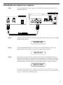
Using the Intellifex Online with a guitar rack system
!! CAUTION !!
Note:
Never connect the outputs of a power amplifier or guitar amplifier to the inputs of the Intellifex Online. This
could damage the Intellifex Online.
For best results when using the Intellifex Online with high gain distortion, always put the Intellifex Online after
the distortion in the signal chain, never before it.
9
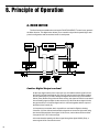
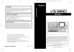
6. Principle of Operation
A. MIXER SECTION
The first function accessible when turning the FUNCTION SELECT control in any preset is
the Mixer function. This digital mixer allows you to control the signal levels pertaining to each
preset’s configuration and stores these levels for each preset.
Caution: Digital Output overload
As the input signal enters at the unit’s input (A), the unaltered direct signal is fed to
the Direct Pre/Post Hush Selector (B). Here you may choose for the direct signal to
remain unaltered (Pre) or feed it through the digital Hush section (E) of the Intellifex
Online (Post). Before being fed to the Hush section, the signal must first be converted
from an analog signal to digital via the converter (D). When the direct signal is fed to
the Hush section, it will remain digital until it is summed together with the output of
the Effects Level control (G).
It is important to remember that it is possible to overload the Digital to Analog
Converter (H) if the effects levels and direct signal level are set too high when using
the Hush section with the direct signal. If this occurs, reduce these levels until the
front panel CLIP L.E.D. does not light.
Also note that when passing the direct signal through the digital HUSH (Post), a
stereo signal will be converted to mono.
10
MIXER PARAMETERS
Effects Level
(in Hush; Chorus; Delay; Reverb and Hush; Pitch Shift; Delay; Reverb configurations)
This controls the level of the entire effect signal. This control should be set
relative to the levels of the Left and Right Direct signals. In configurations
which do not include a master Effects Level, the single effect level parameter (Chorus Level, Delay Level, etc.) is considered the master Effect Level
control.
Left/Right Direct Levels
These controls allow for the left and right Direct signal levels to be set
individually, thereby allowing for panning of the Direct signal to the left or
right output. These controls are available in all configurations.
Direct Hush
This determines whether the direct signal passes through the digital HUSH
section of the Intellifex Online or bypasses it. Selecting "Post" will pass the
Direct signal through the HUSH system while selecting "Pre" will bypass
this section. (Note: Selecting "Post" converts a stereo direct signal to
mono.)
Chorus Level, Delay Level, Reverb Level, etc.
In configurations which include a Master Effects Level control, these control
the level of each individual effect (Chorus, Reverb, etc.). These should be
set relative to each other when defining individual levels. In configurations
which do not include a Master Effects Level control, the individual effect
level acts as a Master effect level.
Left and Right Regeneration (in all configurations except Hush; Reverb )
Configurations which include chorus or delay effects provide individual left
and right regeneration level controls to determine the number of times the
delayed signals are repeated. Regeneration is achieved by feeding the
delayed output back into the input. Higher levels of regeneration will result
in more repeats.
The Intellifex Online provides a Regeneration Limiting feature, which guards
against the possibility of overloading the processor when using high
regeneration levels in configurations where a combination of multiple voices
is panned to the left or right. If the regeneration level is set too high, the
Intellifex Online triggers the Regeneration Limiting and a limit is internally
set for the regeneration. This limit can not be exceeded by increasing the
Regen L or Regen R parameter values in the Mixer section.
If, for example, in the Hush; Chorus; Delay; Reverb configuration, Voice 1
is panned to the left and the Regen L parameter is set to its maximum
level, panning a second voice to the left regeneration loop will trigger the
Regeneration Limiter and reduce the regeneration to a level such that
runaway regeneration will not occur. The original regeneration level can be
reset only by recalling the preset, or, by accessing the Regen L parameter,
decreasing its value and setting it back to its original value after removing
the second Voice from the regeneration loop. This feature of the Intellifex
Online is particularly desirable in live situations where panning and regeneration levels may be controlled by continuous controllers.
11
B. REVERB SECTION
Reverb, or reverberation, is the continuance of sound within a given room or enclosed chamber after the source of the
sound has stopped producing it. More specifically, it is a multitude of echoes so densely spaced that, to the human ear,
seem as a single continuous sound. These echoes gradually decrease in intensity until they are ultimately absorbed by the
boundaries and obstacles within the room or enclosure. As the sound waves from the signal source strike the walls or
boundaries of the room, a portion of the energy is reflected away from the obstacle and another portion is absorbed into it,
thereby causing both the continuance of sound and the decaying or "dying out" of the sound.
REVERB TYPES
The Intellifex Online Hush; Reverb configuration offers 8 different reverb types: Plate A, Plate
B , Room A, Room B, Hall A, Hall B, Stadium and Dual.
The Plate reverb type simulates an artificial method of producing reverberation, popular in the
early years of recording, which involved using a fairly large, but very thin, metal plate suspended at its four corners by steel wires under tension. This metal plate becomes excited by
a driver unit (similar to a dynamic speaker without the diaphragm) and the resulting reverberation is picked up by contact microphones. The Intellifex Online offers two Plate reverb types
which reflect the most common plate characteristics. This type of reverb is often used on
drum and vocal tracks.
Room reverb effects simulate various rooms of different sizes and surfaces. For example, a
room which is made up of primarily hardened surfaces (such as tile or hard wood) will generate reflections containing much more high frequency information than one which is made up of
softer surfaces (such as thick carpeting). The Room reverb effects offered by the Intellifex
Online can generate virtually any imaginable room setting via highly efficient and adjustable
reverb parameters.
Hall reverb simulates the reverberation characteristics of a very large room with a high ceiling.
Reflections in a hall are much longer than a typical room, as the length of time it takes for the
sound waves to travel from one surface to the next is greatly increased.
Stadium reverb simulates the characteristics of a large stadium or arena and should be used
with large amounts of predelay and high frequency damping.
Dual reverb is unique in that it allows for the left and right channels to be processed independently one another. For example, the Predelay for the left channel can be set at 100mS while
the Predelay for the right channel can be set at 200mS. This results in reverb output from the
left channel 100mS before reverb is output from the right channel.
REVERB PARAMETERS
12
Reverb Input
This parameter determines whether the input to the Reverb section is active
(passing a signal) or muted (not passing a signal).
Reverb Level
This parameter determines the level of the reverb signal at the output
relative to the direct signal and any other effect signals. It is accessible
from both the Mixer function and Reverb function parameter lists.
Reverb Decay
This parameter specifies the length of time that the reverb signal will sound
before it has completely faded out (or until its echoes have been ultimately
absorbed by the boundaries within the given "room"). The maximum length
of this decay will vary dependent upon which reverb type is active.
High Freq. Damping
High Frequency Damping is used to control the amount of high frequency
information in the reverb signal.
Low Freq
This parameter determines the amount of low frequency information in the
reverb signal.
Reverb Type
This parameter determines the current active reverb type (Room, Plate,
etc.).
Dir In Pan
This parameter allows you to pan the direct input signal to the reverb
section to the left or right—allowing for only the left or right channel to be
reverberated when used with the Dual reverb type, or, for one channel to be
reverberated to a greater degree than the other. This parameter is adjustable from 0 to 100—where "0" is full left, "100" is full right and "50" is
center.
Predelay L
This parameter determines the amount of time after a signal is input to the
Intellifex Online that the left channel signal will be input to the reverb.
Delaying the reverb signal provides greater separation of the input and
reverb signals and helps to increase the apparent size of the Room, Hall, or
Stadium.
Predelay R
This parameter determines the length of time after a signal is input to the
Intellifex Online that the right channel signal will be input to the reverb.
Gate
Gating the reverb signal closes down the decay of the reverb very quickly
after a prescribed amount of time (most commonly a very short period of
time). This effect is often used on drums (particularly snare drums) to
produce the effect of a much fatter percussive sound. Note that gating on
the Intellifex Online acts on the reverb decay, not on the reverb output as on
many other units.
Gate Decay
The Gate Decay parameter determines how quickly the gate will close
down the reverb decay after the reverb has sounded for the specified time.
Gate Threshold The Gate Threshold determines the threshold point at which gating will take
place. When the signal is below this threshold point for a period of time, the
reverb will be gated. When the input signal peak rises above this threshold,
the gate will open and reverb will be heard.
Hold Time
The Hold Time determines how long the reverb signal will sound before the
gate begins to close.
13
C. DELAY SECTION
Delay is simply a reproduction of the input signal, originating at a prescribed time (usually expressed in milliseconds, or
mS) following the input signal.
DELAY TYPES
The Intellifex Online HUSH; Delay; Ducker configuration offers 3 delay types: Stereo,
Ping-Pong and 2-Tap.
The Stereo delay type provides two separate delays. This delay type is used for applications requiring two discrete delay lines with individual regeneration loops.
The Ping-Pong delay type regenerates each delay’s output into the opposite delay’s
input instead of its own. This causes the delayed signals to bounce back and forth from the
left channel to the right (provided the delay outputs are panned left and right).
The 2-Tap delay type provides a single long delay line with two outputs and offers twice
the delay time of the Stereo delay type.
DELAY PARAMETERS
Delay
This parameter determines whether the Delay section is active (passing a
signal) or muted (not passing a signal).
Mute Type
This parameter allows for muting of the Delay section at its input (Pre), its
output (Post) or both.
Muting the input (Pre) of the delay restricts any signal from entering the
delay section until the delay is switched in. When using a moderate
amount of regeneration, switching out the delay with the input muted will
generate a non-delayed signal which will play over the decaying regenerated signal which continues on after the delay is switched out.
Muting the output (Post) of the delay results in the delayed signal being
immediately turned off when the delay is switched out. This means that
delays and regeneration will not continue once the delay is switched out. If
the output were not muted, signals input before switching the delay out
would be allowed to regenerate - even after switching out the delay.
It is also possible to mute both the input and output (Both) so that no
signal enters or exits the Delay section when it is not switched in.
Level 1/2
14
These are individual level controls for each of the two delays available in the
Delay section. These are not the same as the Delay Level parameter found
in the Mixer function (which adjusts the overall level of both delay signals).
Pan 1/2
This allows for the panning of each delay to the left or right output, if
desired. The Pan parameter is adjustable from 0 to 100—where 0 is full left,
100 is full right and 50 is center.
Dly Time 1/2
These parameters determine the amount of time after a signal is input that
the delayed signal will begin to reproduce the input signal.
Regen 1/2
This parameter is provided for each delay and determines the number of
times the delayed signal will repeat itself. This is achieved by feeding the
delayed output back into the input. Higher levels of regeneration will result
in more repeats.
D Type
The Delay Type parameter determines whether the Stereo, Ping-Pong or 2Tap delay type is currently active.
Dl Hf Damp
Delay High Frequency Damping determines the amount of high frequency
content in the delayed and regenerated signals. Higher amounts of damping
will result in less high frequency information in the delayed signal.
15
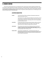
D. DUCKER SECTION
The process of ducking enables the user to suppress the level of a given signal or effect dynamically, dependent upon
the presence of another signal which is desired to be prominent. The ducking feature of the Intellifex Online works in conjunction with the Delay and Reverb sections to attenuate the delay and/or reverb level while a phrase is being played (resulting in
a less cluttered, more intelligible sound), yet return each to its original level when the phrase ends—thus allowing for the full
decay of the delayed and/or reverberated signal.
DUCKER PARAMETERS
Ducker
In the HUSH; Delay; Ducker configuration, this parameter determines
whether the Ducker is off or on.
In the HUSH; Chorus; Delay; Reverb and HUSH; Pitch Shift; Delay; Reverb
configurations, this parameter determines whether the Ducker is either (A)
off, (B) operating on the delay, (C) operating on the reverb, or (D) operating
on both the delay and reverb.
16
Sensitivity
This parameter determines the threshold point above which the ducker will
begin attenuating the delay and/or reverb signal. Until the input signal
reaches this level, the delay/reverb signal will not be affected.
Attenuation
This parameter determines how much the delayed signal is attenuated
(muted). It may be set for only a slight change in signal level or it can
completely attenuate the delay/reverb signal so that no delayed or reverberated signal passes while ducking is active.
Release Rate
This parameter is adjustable from .2 seconds to 9 full seconds, and
determines the length of time it takes for the muted delay signal to return to
its original signal level after the input signal falls below the threshold point
set by the Sensitivity parameter.
E. PITCH CHANGE SECTION
Pitch Change effects involve splitting the input signal into at least two separate signals, then modifying the pitch of one
signal and mixing it back together with the unaltered direct signal. The Intellifex Online offers two types of pitch change
effects: Chorus and Pitch Shift.
CHORUS
The Chorus effect is achieved by using one or more delayed signals, detuning these
delayed signals (slightly changing their pitch) then modulating this detune effect so that the
amount of pitch detune is constantly varying. Using many delayed signals at different delay
lengths - as well as using different detune amounts, modulation rates and modulation depths
for each delayed signal—results in a rich, spacious stereo chorused signal.
CHORUS PARAMETERS
Level (Individual Voices)
This parameter adjusts the volume of the delayed signal relative to the other
voice(s) of the effect and is included in the parameter list for each voice (or
each delay signal) of both the 8-Voice and 4-Voice Chorus effects. (This
level control is not the same as the Chorus Level found in the Mixer function
parameter list.)
Pan
The Pan parameter allows you to pan each voice (or delay) of the chorused
signal to the left or right channel. This parameter is adjustable from 0 to
100—where 0 is full left, 100 is full right and 50 is center.
Delay
The Delay parameter determines the delay time (in milliseconds) for each
tap of the chorus signal. It is this delayed signal that is detuned and
modulated to produce the chorus effect. Using shorter delay times for this
effect produces a tighter sounding chorused signal, while using longer delay
times will achieve a much larger, ambient effect.
Depth
The Depth parameter adjusts the amount of modulation of each delayed
signal. A lower depth setting will produce a more subtle detune effect while
a higher setting of this control will cause a more drastic detuning of the
delayed signal.
Rate
The Rate parameter determines the sweep speed for the delayed signal
(i.e. the speed at which the delayed signal is modulated). Here a low rate
results in a slow speed and a higher rate results in a faster speed.
17
PITCH SHIFT
Pitch Shifting is used to change the pitch of the input signal to produce one to four harmony notes based on a single
input signal. The Hush; Pitch Shift; Delay configuration offers 4 harmony voices while the Hush; Pitch Shift; Delay; Reverb
configuration offers 2. Each harmony voice may be of any fixed interval - from to one octave above the input signal to two
octaves below—and is selected in 20 cent increments. Increments of one cent (1/100th of a semitone) are also available for
fine adjustment via the Fine parameter.
PITCH SHIFT PARAMETERS
18
Pitch
The Pitch parameter determines the harmony note the Intellifex Online will
produce based on the input note. An interval is the distance in semitones
between the pitches of two musical tones (i.e. the distance from an A note
to a C note is considered a minor third interval, this equals 3 half-steps or
300 cents). The Pitch parameter is adjustable in 20 cent increments and
any interval may be selected from one octave above to two octaves below
the input signal. This parameter is adjustable from -2400 cents to +1200
cents—where -2400 is 2 octaves below the input signal, 0 is unison and
+1200 is one octave above the input signal. Each 100 cents (or 5 - 20 cent
steps) above or below 0 represents the amount of half-steps (or semitones)
the harmony note will be above or below the input signal.
Fine
The Fine parameter allows for fine adjustment of pitch change in 1 cent
steps (or 1/100th of a semitone) for finer adjustment of the harmony note.
Level
The Level parameter determines the volume of each voice relative to the
other voices of the effect. (This is not the same as the Pitch Shift Level
parameter found in the Mixer Function parameter list.)
Pan
This parameter allows you to pan the shifted note to the left or right channel
of the Intellifex Online. It is adjustable from 0 to 100, where 0 is full left, 100
is full right and 50 is center.
Delay
This parameter allows for the shifted signal to be delayed up to 418mS
following the input signal. It is adjustable from 0 to 418mS in 2mS increments.
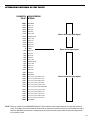
DETERMINING INTERVALS BY CENT VALUES
PARAMETER CORRESPONDING
VALUE INTERVAL
+1200
+1100
+1000
+900
+800
+700
+600
+500
+400
+300
+200
+100
0
-100
-200
-300
-400
-500
-600
-700
-800
-900
-1000
-1100
-1200
-1300
-1400
-1500
-1600
-1700
-1800
-1900
-2000
-2100
-2200
-2300
-2400
One octave
Major 7th
minor 7th
Major 6th
minor 6th
perfect 5th
diminished 5th
perfect 4th
Major 3rd
minor 3rd
Major 2nd
minor 2nd
Unison
Major 7th
minor 7th
Major 6th
minor 6th
perfect 5th
diminished 5th
perfect 4th
Major 3rd
minor 3rd
Major 2nd
minor 2nd
One octave
One octave plus a Major 7th
One octave plus a minor 7th
One octave plus a Major 6th
One octave plus a minor 6th
One octave plus a perfect 5th
One octave plus a diminished 5th
One octave plus a perfect 4th
One octave plus a Major 3rd
One octave plus a minor 3rd
One octave plus a Major 2nd
One octave plus a minor 2nd
Two octaves
Voices above the input signal
Equal to the input signal
Voices below the input signal
NOTE: There are 5 steps of the PARAMETER ADJUST control between each of these intervals, as each step equals 20
cents. This allows for use of the Pitch parameter with an expression controller (such as a volume pedal used with a
Rocktron Midi Mate foot controller to change the pitch by remote means) and provides smooth pitch change when
the controller is used.
19
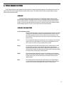
F. HUSH® SECTION
HUSH® is Rocktron’s patented single-ended noise reduction system. The HUSH system contained in the Intellifex Online
is Hush Systems' first fully digital implementation of HUSH achieved through Digital Signal Processing (DSP), and is modeled
after the latest HUSH design.
The low level expander of the HUSH system operates like an electronic volume control. The analog design utilizes a
voltage-controlled amplifier (VCA) circuit which can control the gain between the input and output from unity to 30, 40 or even
50dB of gain reduction. When the input signal is above the user preset threshold point, the VCA circuit is at unity gain. This
means that the amplitude of the output signal will be equal to that of the input signal. As the input signal amplitude drops
below the user preset threshold point, downward expansion begins. At this point the expander operates like an electronic
volume control and gradually begins to decrease the output signal level relative to the input signal level. For example, if the
input signal were to drop below the threshold point by 2dB, the output would drop approximately 3dB. As the input signal
drops further below the threshold point, downward expansion increases. For example, if the input signal dropped 6dB below
the threshold point, the output level would drop by approximately 14dB. A drop in the input level by 20dB would cause the
output level to drop by approximately 54dB (i.e. 34dB of gain reduction). In the absence of any input signal, the expander will
reduce the gain such that the noise floor becomes inaudible.
HUSH PARAMETERS
20
Hush I/O
This parameter simply determines whether the HUSH circuit will be in the
signal path or bypassed.
Exp Thresh
The Expander Threshold parameter determines the level at which downward
expansion begins. For example, if the expander threshold was set at -20dB
and the input signal dropped below -20dB, downward expansion would
begin. Typically, this parameter should be set between 5-20dB above the
quiescent noise floor of the input signal (i.e. if the noise floor was -60dB, a
setting between -40 and -55dB will produce the proper expansion).
Rel Rate
The Release Rate parameter determines the amount of time required for the
downward expander to decrease the level of the output signal. This rate is
adjustable from 25mS to 800mS to accommodate a wide variety of applications. For example, when using the expander for gating applications on
drums, a very quick release rate (25-200mS) should be used. When used
with individual instruments such as guitar, a setting of 200mS or higher will
provide adequate expansion without being as harsh as a gate. When used
with sources which have long decay times (cymbals, etc.) a very slow
release rate should be used.
7. Configurations
At the root of each preset’s sound is its configuration. A preset's configuration determines
both the active effects for a given preset and the order in which those effects are routed in the
signal path. The Intellifex Online provides 6 highly flexible configurations capable of producing
sounds which previously could only be achieved by using numerous effects devices complexly
patched together. These configurations offer many simultaneous effects without degradation of
the sound quality of each effect.
Selecting a Configuration
To select a specific configuration, press the CONFIG button—the CONFIG LED above the
button will light and the Intellifex Online will display the configuration for the current preset.
Turning the PRESET control while in this mode will step through each preset, displaying each
preset's configuration instead of its preset number and title.
The basic signal path arrangements for each of the Intellifex Online configurations are
shown in this section, as well as their respective parameter lists. These diagrams illustrate
the various signal flow possibilities available via the MIX, PAN and LEVEL controls located at
various points in the signal chain.
21
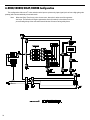
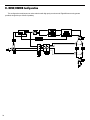
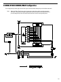
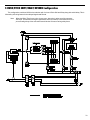
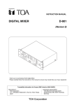
A. HUSH/CHORUS/DELAY/REVERB Configuration
This configuration offers HUSH® noise reduction at the input to quiet a noisy input signal (such as from a high-gain guitar
preamp) with 4 chorus and delay voices and reverb.
Note:
22
When the Delay Time for any voice is set to zero, that voice is taken out of the regeneration loops. This will allow for higher regeneration levels (if needed). It also allows for a more
pure sounding decay of the echo when used with other voices set at long delay times.
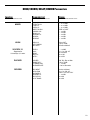
HUSH/CHORUS/DELAY/REVERB Parameters
Function
Parameter List
Range
via FUNCTION SELECT control
via PARAMETER SELECTcontol
via PARAMETER ADJUST control
MIXER
EFFECTS LVL
L DIR LVL
R DIR LVL
DIRECT HUSH
CHORUS LVL
DELAY LVL
REVERB LVL
REGEN L
REGEN R
-∞ to +6.0dB
-∞ to +6.0dB
-∞ to +6.0dB
PRE or POST
-∞ to 0dB
-∞ to 0dB
-∞ to 0dB
-∞ to 0dB
-∞ to 0dB
HUSH
HUSH I/O
EXP THRESH
REL RATE
IN or OUT
-92 to -20dB
25mS to 800mS
LEVEL 1
PAN 1
DELAY
DEPTH 1
RATE 1
- ∞ to 0dB
L<- 0 to 100 ->R
0 to 418mS
0 to 100
0 to 254
DUCKER
DUCKER
SENSITIVITY
ATTENUATION
RELEASE RATE
Off, Dly, Rev or Both
-92 to -20dB
-∞ to 0dB
.2 to 9.0 Seconds
REVERB
REV INPUT
DIR IN PAN
MIX DIR/DLY
REVERB LVL
REV DECAY
RV HF DAMP
Active or Muted
L<- 0 to 100 ->R
DlR<- 0 to 100 ->DLY
-∞ to 0dB
0 to 99
0 to 99
VOICE/DLY 1
Repeated for
Voices/Dlys 2, 3 and 4
23
B . HUSH/REVERB Configuration
This configuration combines HUSH® noise reduction with high purity reverb sounds. Eight different reverb types are
provided, along with up to 210mS of predelay.
24
HUSH/REVERB Parameters
Function
Parameter List
Range
via FUNCTION SELECT control
via PARAMETER SELECT control
via PARAMETER ADJUST control
MIXER
REVERB LVL
L DIR LVL
R DIR LVL
DIRECT HUSH
-∞ to +6.0dB
-∞ to +6.0dB
-∞ to +6.0dB
PRE or POST
HUSH
HUSH l/O
EXP THRESH
REL RATE
IN or OUT
-92 to -20dB
25mS to 800mS
REVERB LVL
REVERB DECAY
RV HF DAMP
LOW FREQ
REV TYPE
-∞ to 0dB
0 to 99
0 to 99
0 to 99
Plate A, Plate B, Room A, Room B,
Dual, Hall A, Hall B, Stadium
L<- 0 to 100 ->R
0 to 209mS
0 to 209mS
On or Off
0 to 31
-92 to -20dB
0 to 99
REVERB
DIR IN PAN
PREDELAY L
PREDELAY R
GATE
GATE DECAY
GATE THRESH
HOLD TIME
25
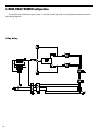
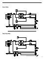
C. HUSH/DELAY/DUCKER Configuration
The Intellifex Online offers three types of delay—2-Tap, Stereo and Ping-Pong. The configurations for each are shown in
the following diagrams.
2-Tap Delay
26
Stereo Delay
Ping-Pong Delay
27
HUSH/DELAY/DUCKER Parameters
Function
Parameter List
Range
via FUNCTION SELECT control
via PARAMETER SELECTcontrol
via PARAMETER ADJUST contol
MIXER
DELAY LVL
L DIR LVL
R DIR LVL
DlRECT HUSH
-∞ to +6.0dB
-∞ to +6.0dB
-∞ to +6.0dB
PRE or POST
HUSH
HUSH l/O
EXP THRESH
REL RATE
IN or OUT
-92 to -20 dB
25mS to 800mS
DELAY
DELAY
MUTE TYPE
LEVEL 1
PAN 1
DLY TIME 1
REGEN 1
LEVEL 2
PAN 2
DLY TIME 2
REGEN 2
D TYPE
DL HF DAMP
Muted or Active
PRE, POST or BOTH
-∞ to 0dB
L<- 0 to100 ->R
0 to 750mS (1500mS - 2 Tap)
-∞ to 0dB
-∞ to 0dB
L<- 0 to l00 ->R
0 to 750mS (1500mS - 2 Tap)
-∞ to 0dB
2-Tap, Stereo, or Ping Pong
0 to 99
DUCKER
SENSITIVITY
ATTENUATION
RELEASE RATE
Off or On
-92 to -20dB
-∞ to 0dB
.2 to 9.0 Seconds
DUCKER
28
D. HUSH/8 VOICE CHORUS/DELAY Configuration
This configuration provides eight voices which may be chorused and/or delayed up to 418 milliseconds each.
Note:
When the Delay Time for any voice is set to zero, that voice is taken out of the regeneration loops. This will allow for higher regeneration levels (if needed). It also allows for a more
pure sounding decay of the echo when used with other voices set at long delay times.
29
HUSH/8 VOICE CHORUS/DELAY Parameters
Function
Parameter List
Range
via FUNCTION SELECT control
via PARAMETER SELECT control
via PARAMETER ADJUST contol
MIXER
CHORUS LVL
L DIR LVL
R DIRLVL
DIRECT HUSH
REGEN L
REGEN R
-∞ to +6.0dB
-∞ to +6.0dB
-∞ to +6.0dB
Pre or Post
-∞ to 0.0dB
-∞ to 0.0dB
HUSH
HUSH 1/0
EXP THRESH
REL RATE
In or Out
-92 to -20dB
25mS to 800mS
LEVEL 1
PAN 1
DELAY 1
DEPTH 1
RATE 1
-∞ to 0dB
L<- 0 to 100 ->R
0 to 418mS
0 to 100
0 to 254
VOICE/DLY 1
Repeated for Voices 2 - 8
30
E. HUSH/PITCH SHIFT/DELAY Configuration
31
HUSH/PITCH SHIFT/DELAY Parameters
Function
Parameter List
Range
via FUNCTION SELECT control
via PARAMETER SELECT control
via PARAMETER ADJUST control
MIXER
P SHIFT LVL
L DIRLVL
R DIR LVL
DIRECT HUSH
REGEN L
REGEN R
-∞ to +6.0dB
-∞ to +6.0dB
-∞ to +6.0dB
Pre or Post
-∞ to 0.0dB
-∞ to 0.0dB
HUSH
HUSH l/O
EXP THRESH
REL RATE
In or Out
-92 to -20dB
25mS to 800mS
PITCH 1
FINE 1
LEVEL 1
PAN 1
DELAY1
-2400 to +1200
-20 to +20
-∞ to 0.0dB
L<- 0 to 100 -> R
0 to 418mS
VOICE 1
Repeated for
Voices 2,3 and 4
32
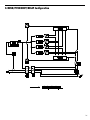
F. HUSH/PITCH SHIFT/DELAY/REVERB Configuration
This configuration combines HUSH noise reduction with 2 voices of Pitch Shift and Delay along with a third delay. This is
followed by a Ducking feature for the delayed signals and Reverb.
Note:
When the Delay Time for any voice is set to zero, that voice is taken out of the regeneration loops. This will allow for higher regeneration levels (if needed). It also allows for a more
pure sounding decay of the echo when used with other voices set at long delay times.
33
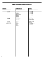
HUSH/PITCH SHIFT/DELAY/REVERB Parameters
34
Function
Parameter List
Range
via FUNCTION SELECT control
via PARAMETER SELECT control
via PARAMETER ADJUST contol
MIXER
EFFECT LVL
L DIR LVL
R DIR LVL
DIRECT HUSH
PSHIFT LVL
DELAY LVL
REVERB LVL
REGEN L
REGEN R
-∞ to +6.0dB
-∞ to +6.0dB
-∞ to +6.0dB
Pre or Post
-∞ to 0.0dB
-∞ to 0.0dB
-∞ to 0.0dB
-∞ to 0.0dB
-∞ to 0.0dB
HUSH
HUSH I/0
EXP THRESH
In or Out
-92 to -20dB
VOICE/DLY 1
PITCH 1
FINE 1
LEVEL 1
PAN 1
DELAY 1
-2400 to +1200
-20 to +20
-∞ to 0.0dB
L<- 0 to 100 ->R
0 to 418mS
VOICE/DLY 2
PITCH 2
FINE 2
LEVEL 2
PAN 2
DELAY 2
-2400 to +1200
-20 to +20
-∞ to 0.0dB
L<- 0 to 100 ->R
0 to 418mS
DELAY 3
LEVEL 3
PAN 3
DELAY 3
-∞ to 0.0dB
L<- 0 to 100 ->R
0 to 418mS
DUCKER
DUCKER
SENSITIVITY
ATTENUATION
RELEASE RATE
Off, Dly, Rev or Both
-92 to -20dB
-∞ to 0dB
.2 to 9.0 Seconds
REVERB
REV INPUT
DIR IN PAN
MIX DIR/DLY
REVERB LVL
REVERB DECAY
RV HF DAMP
Active or Muted
L<- 0 to 100 ->R
DlR<- 0 to 100 ->DLY
-∞ to 0dB
0 to 99
0 to 99
8. Operating the Intellifex
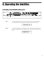
A. Recalling a stored Intellifex Online preset
2
Step 1
1
To recall an Intellifex Online preset, first turn the PRESET control to the preset number to
be recalled. The display will alternate between the preset number/title selected and:
PRESS RECALL FOR
Step 2
To recall the selected preset, press the RECALL button and the display will now show only
the new preset number and title (or configuration type—depending on the CONFIG L.E.D.
status).
14 PRESET TITLE
35
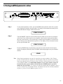
B. Changing preset parameters
4
Step 1
3
2
1
The parameter menu for each effect can be called up via the FUNCTION SELECT control.
Turn this control to the effect to be modified.
***** REVERB *****
Step 2
Turn the PARAMETER SELECT control to choose which parameter to be altered for that
effect.
REV DECAY
Step 3
Use the PARAMETER ADJUST control to modify the parameter value. The LED above
the STORE button will light, indicating that the preset has been altered from its original state.
REV DECAY
Step 4
32
The COMPARE button may be used to compare the old parameter value to the new one.
REV DECAY
36
59
59
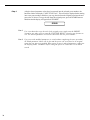
C. Storing modified parameter values
2
1,3,4
To store altered parameter values, press the STORE button while the effect title or parameter is displayed to start the store procedure. The display will alternate between the preset
number/title that the changes will be stored to and:
Step 1
STORE TO PRESET
Step 2
Turn the PRESET control to select the desired preset number to store the new parameter
values into (if you wish to store the new parameter values into the current preset number,
this step is not necessary). User presets may be stored in preset numbers 1-80. Presets 81160 are factory presets and cannot be copied over. The display will now alternate between
the new preset number and:
STORE TO PRESET
Press the STORE button a second time to store the new values into the selected preset
number. The display will briefly flash "STORED" before displaying the new preset number
and title.
Step 3
STORED
Note
Altered preset parameters can only be stored in user preset numbers 1-80. Factory
presets 81-160 cannot be copied over, and therefore cannot be selected as a destination for an altered preset. If a factory preset (81-160) is altered and you wish to store
it, the Intellifex Online will automatically default to a user preset number exactly 80
less than the factory preset number selected when the STORE button is pressed to
initiate the store procedure (i.e. if preset 81 has been altered and you attempt to store it
at preset location 81, the Intellifex Online will default and store the altered parameters
to preset 1, preset 125 will default to preset 45, etc.).
37
Step 4
After the altered parameter values have been stored into the selected preset number, the
Intellifex Online will display "COPY TITLE TOO?". This will only be displayed when storing
into a new preset number, and allows you copy the title from the original preset into the new
preset also, if desired. To copy the title from the original preset, press the STORE button a
third time and the display will again flash "STORED".
STORED
38
Note 1
If it is not desired to copy the title of the original preset, simply turn the PRESET
control to any other preset or turn the FUNCTION SELECT control to any function to
exit. The altered parameters will still be stored into the new preset number.
Note 2
If a preset with modified parameters is exited without completing the store procedure,
all edited parameter values will be lost and the preset will revert back to its original
status the next time it is recalled. When saving a preset’s altered parameters, make sure
the display flashes "STORED" before exiting the preset to ensure that it was indeed
stored.
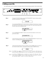
D. Editing a preset title
The Title Edit function can be accessed in user presets 1-80 only. The titles of factory presets 81-160 can not be edited.
3
5
2,4
1
To begin the Title Edit function, turn the FUNCTION SELECT control clockwise until the
Intellifex Online displays "TITLE EDIT".
Step 1
TITLE EDIT
Turn the PARAMETER SELECT control clockwise to initiate the Title Edit mode. Turning
this control will select the character location to be edited. The current character position to
be edited is followed by a flashing decimal.
Step 2
29 P.RESET TITLE
Flashing decimal
Use the PARAMETER ADJUST control to select the desired character for the current
position to be edited.
Step 3
29 N.RESET TITLE
Step 4
To edit the character in the next position, turn the PARAMETER SELECT control one step
clockwise - the flashing decimal will move to the next position.
29 NR.ESET TITLE
Flashing decimal
at next position
Step 5
After all the desired characters have been edited, press the STORE button to save the new
title in Intellifex Online memory. The Intellifex Online will flash "STORED" briefly.
STORED
Note 1
The STORE button must be pressed to save the new title. Exiting the Title Edit function
before pressing the STORE button will erase any editing done in the Title Edit function.
Note 2
After flashing "STORED" briefly, the Intellifex will remain in Title Edit mode. You may
either (a) turn the PRESET control to display and edit other preset titles, or, (b) turn
the FUNCTION SELECT control to exit the Title Edit function.
39
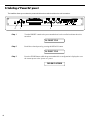
E. Selecting a "Power On" preset
The Intellifex allows you to select the preset which that be recalled each time the unit is turned on.
2
Step 1
1
3
Turn the PRESET control to the preset number that is to be recalled each time the unit is
turned on.
24 PRESET TITLE
Step 2
Recall the selected preset by pressing the RECALL button.
24 PRESET TITLE
Step 3
Press the STORE button while the preset number/title or configuration is displayed to save
the current preset as the "power on" preset.
PWR ON PR STORED
40
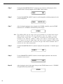
9. MIDI Operation
A. MIDI Controller Assignment
Controller mapping allows for specific Intellifex adjustable parameters to be mapped (or assigned) to a MIDI controller
number for real-time control (via a pitch wheel, expression pedal, etc.) in live performance situations. Any parameter may be
assigned to any controller number, from controller 0 through controller 120, or OFF. In the OFF position, the assigned
parameter will not respond to any MIDI control change. Each preset allows for up to 8 controllers.
The Controller Assign function is accessible in user presets 1-80. Factory presets 81-160 do not include this function.
3,6,9,12
Step 1
4,7,10,13
2,5,8,11
1
To access the Controller Assign function, turn the FUNCTION SELECT control one step
clockwise past "Title Edit".
CONTROLLER ASSIG
Step 2
Turn the PARAMETER SELECT control to access the first parameter of the Controller
Assign function. This parameter allows for the selection of a controller number which the
first parameter (selected in Step 5) will respond to.
NUMB1
Step 3
XXX
Use the PARAMETER ADJUST control to select the controller number to be assigned to
the first parameter (PARA1). You may choose any number from 0 to 120, or OFF so that
the parameter will not respond to MIDI controller changes. Match this number with the
MIDI transmitter controller number.
NUMB1
Step 4
7
After selecting the desired controller number, press the STORE button to save the number.
"STORED" will flash briefly on the display.
STORED
41
Step 5
Turning the PARAMETER SELECT control one step clockwise will display the effect
parameter that is currently mapped to the NUMB1 control number.
PARA1
XXX
Turn the PARAMETER ADJUST control to scroll through the available parameters for the
current configuration.
Step 6
PARA1
Step 7
EFFECTS LVL
After selecting the parameter to be assigned to the NUMB1 controller, press the STORE
button to save it. "STORED" will flash briefly on the display.
STORED
Note
Step 8
The Intellifex allows for the range of any given parameter to be limited when using a
MIDI controller to determine the current parameter value. For example, if a given
parameter has a range from -∞ to +6dB yet it is desirable for the full range of the
controller to vary from only -10dB to +2.5dB, a lower limit of -10 and an upper limit
of +2.5 may be set via the "Upper Limit" and "Lower Limit" parameters. When storing
a parameter, the maximum value is stored as the upper limit and the minimum value is
stored as the lower limit automatically.
Turn the PARAMETER SELECT control to display the next parameter - "Controller Upper
Limit".
ULIM C1
Step 9
Use the PARAMETER ADJUST control to select the highest parameter value that the
controller is not to exceed.
ULIM C1
Step 10
+2.5
After selecting the value for the upper limit, press the STORE button to save it. "STORED"
will again flash briefly on the display.
STORED
42
XXX
Step 11
Turn the PARAMETER SELECT control for the last parameter - Controller Lower Limit.
LLIM C1
Step 12
XXX
Use the PARAMETER ADJUST control to select the parameter value which the controller
is not to fall below.
LLIM C1
Step 13
-10.0
After choosing a lower limit parameter value, press the STORE button to save it.
"STORED" will flash briefly on the display.
STORED
Notes
This entire process is repeated 7 times for a total of 8 controllers (NUMB2, NUMB3,
etc.). To exit Controller Assign at any time, turn the PRESET or FUNCTION SELECT
controls. Only those changes that have been stored will be saved after exiting Controller Assign.
Also, a lower limit may be selected which is greater than the upper limit. This will invert
the response of the controller. For example, the toe position of an expression pedal
would provide the minimum value while the heel position would provide the maximum
value.
43
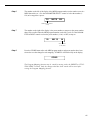
B. MIDI Program Mapping
Program mapping allows for an Intellifex preset number to be mapped (or assigned) to a different MIDI program number.
The Intellifex is initially programmed at the factory to access to the lower 128 presets (i.e. program number 1 is mapped to
preset 1, 128 to 128, etc.)
3,7
Step 1
4,8
2,5,6
1
To access the Program Mapping function, turn the FUNCTION SELECT control one step
past the Controller Assign function.
** PROG MAPPING **
Step 2
Use the PARAMETER SELECT control to select the first parameter—Program Mapping
Status. This parameter determines whether program mapping is on or off. When program
mapping is OFF, the preset number recalled is identical to the program number sent via
MIDI. When ON, the preset number recalled is the preset that the program number sent is
mapped to.
PROG MAPPING
Step 3
Select whether the program mapping is to be ON or OFF via the PARAMETER ADJUST
control.
PROG MAPPING
Step 4
OFF
ON
Save the current Program Mapping status by pressing the STORE button. "STORED" will
flash briefly on the display.
STORED
Step 5
Turn the PARAMETER SELECT control one step clockwise to view the current map
settings. This parameter allows you to map MIDI program numbers to specific presets.
XXX
44
MAP TO
XXX
Step 6
The number on the left of the display is the MIDI program number (or the number sent via a
MIDI footswitch, etc.). Use the PARAMETER SELECT control to select the number (1128) to be mapped to a preset.
110
MAP TO
XXX
MIDI Program Number
(1-128)
Step 7
The number on the right of the display is the preset number to map to (or the preset number
that will be recalled when the MIDI program number on the left is sent). Use the PARAMETER ADJUST control to select the preset number (1-160, or OFF) to map to.
110
MAP TO
56
Preset Number
(1-160, OFF)
Step 8
Press the STORE button after each MIDI program number and preset number have been
selected to save the change for each mapping. "STORED" will flash briefly on the display.
STORED
The Program Mapping function may be exited by turning either the PRESET or FUNCTION SELECT control. Only the changes that have been stored will be saved after
exiting the Program Mapping function.
45
C. MIDI Channel
The MIDI Channel function determines the MIDI channel that the Intellifex Online will receive MIDI commands on.
3
Step 1
4
2
1
Turn the FUNCTION SELECT control to "MIDI Channel".
** MIDI CHANNEL **
Step 2
Turn the PARAMETER SELECT to view the current MIDI Channel.
MIDI CHANL
Step 3
Use the PARAMETER ADJUST control to select the MIDI channel that the Intellifex
Online is to receive MIDI commands on. Channels 1-16, OMNI (all channels), or OFF (will
not receive MIDI commands) may be selected.
MIDI CHANL
Step 4
OMNI
10
Press the STORE button to save the new MIDI channel status. "STORED" will briefly flash
on the display.
STORED
To exit the MIDI Channel function, turn either the PRESET or FUNCTION SELECT
control. Any changes made must be stored to be saved after exiting the MIDI Channel
function.
46
D. MIDI Dump/Load
Any or all of the Intellifex Online user presets may be dumped to a sequencer or another Intellifex Online via system
exclusive messages. The information exchanged when performing a MIDI dump consists of the configuration type, parameter
values, title characters and controller assignment/limit information. When dumping a single Intellifex Online preset into
another Intellifex Online, the preset being dumped may be loaded into any user preset location on the receiving Intellifex
Online.
Dumping a single Intellifex Online user preset into another Intellifex Online:
Step 1
Using a standard MIDI cable, connect the MIDI OUT of the transmitting Intellifex Online to
the MIDI IN of the receiving Intellifex Online. Do not connect the other MIDI ports together.
Step 2
Turn the FUNCTION SELECT knob on both units to "MIDI Dump/Load".
MIDI DUMP/LOAD
Step 3
Turn the PARAMETER SELECT knob on the transmitting Intellifex Online to "Preset
Dump". (The current preset number will also be displayed.)
54 PRESET DUMP
Step 4
Turn the PARAMETER SELECT control on the receiving Intellifex Online to "Preset Load".
(The current preset number will also be displayed.)
78 PRESET LOAD
47
Step 5
Use the PRESET control on the transmitting Intellifex Online to select the preset you wish to
dump. Any of the user presets (1-80) may be dumped.
17 PRESET DUMP
Step 6
Use the PRESET control on the receiving Intellifex Online to select the preset location to
store the received preset. The preset currently at this location will be overwritten, therefore
use caution when selecting the preset location to dump to.
25 PRESET LOAD
Step 7
Press the STORE button on the transmitting Intellifex Online to initiate the dump. The
transmitting Intellifex Online will display the preset number of the preset dumped and
"DUMPED". The receiving Intellifex Online will display the preset location being stored to
and "RECEIVING...” while it receives and stores the preset's parameters, title and controller information.
After all information for that preset is stored, the receiving Intellifex Online will display
"LOADED" and the preset number. The receiving Intellifex Online also recalls the loaded
preset at this time so that it may be verified.
17 DUMPED
Transmitting Intellifex
25 LOADED
Receiving Intellifex
48
The following information is transmitted when a preset dump is initiated:
F0H - Start of Exclusive byte
00H - Manufacturer ID byte 1
00H - Manufacturer ID byte 2
29H - Manufacturer ID byte 3
02H - Product ID byte
28H - Command byte, Preset dump
XXH - 200 data bytes, (MSB=0)
YYH - Check Sum byte, ("Exclusive or" of data bytes, MSB=0)
F7H - End of Exclusive byte
Each data byte is a 7-bit value. The first transmitted data byte consists of the lower 7 bits of the first value. The second
transmitted data byte consists of the most significant bit of the first value. These two transmitted bytes are combined when
received to form the first value. The next two transmitted bytes will form the next value in the same way and so on, until all
200 bytes are transmitted. The order of data byte transmission is as follows:
55 Parameter values X 2 = 110 transmitted bytes
13 Title characters X 2 = 26 transmitted bytes
32 Control Assignments X 2 = 64 transmitted bytes
200 total transmitted data bytes
The Check Sum byte is the "Exclusive Or" operation of all the data bytes, with the most significant bit = 0.
Dumping the Intellifex user memory into a sequencer:
Step 1
Connect the MIDI OUT of the Intellifex Online to the MIDI IN on the sequencer using a
standard MIDI cable.
49
Step 2
Turn the FUNCTION SELECT control on the Intellifex Online to the "MIDI DUMP/
LOAD" function. This function is available at the most clockwise position of the FUNCTION SELECT control in all user presets.
MIDI DUMP/LOAD
Step 3
Turn the PARAMETER SELECT control to the "DUMP USER DATA" position.
DUMP USER DATA
Step 4
Start the sequencer recording.
RECORD
Step 5
Press the STORE button on the Intellifex Online to initiate the user data dump. The Intellifex
Online will display the number of the data string as it is dumped. Data strings 1-80 are the
user presets as described by the preset dump function, while data string 81 is the program
mappings. Data string 82 contains the footswitch types, MIDI channel, mapping status, and
"power on" preset. After all the user data is transmitted, the Intellifex Online will display
"USER DATA DUMPED". The process takes approximately 3 minutes to complete.
USER DATA DUMPED
After the Intellifex Online displays "USER DATA DUMPED", stop the sequencer. The
sequencer should have recorded all of the data. Keep the data stored on a disk and
kept in a safe place.
50
Reloading the user memory from a sequencer:
Step 1
Connect the MIDI OUT of the sequencer to the MIDI IN on the Intellifex Online with a
standard MIDI cable.
Step 2
Turn the FUNCTION SELECT control on the Intellifex Online fully clockwise to the "MIDI
DUMP/LOAD" position.
MIDI DUMP LOAD
Step 3
Turn the PARAMETER SELECT control to the "LOAD USER DATA" position. The
Intellifex Online is now ready to receive the user data from the sequencer.
LOAD USER DATA
Step 4
Play back the user data previously recorded on the sequencer. The Intellifex Online will
display the data strings as it is storing them. The data string and "LOADED" will appear on
the display. After all the user data has been loaded the Intellifex Online will display "USER
DATA LOADED". The entire procedure will take approximately 3 minutes to complete.
USER DATA LOADED
Do not play back data from the sequencer faster than it was recorded, as errors may
occur. Errors may also occur if any knob is turned or any button is pressed before the
message “USER DATA LOADED”appears.
51
The following information is transmitted when a user data dump is initiated:
F0H - Start of Exclusive byte
00H - Manufacturer ID byte 1
00H - Manufacturer ID byte 2
29H - Manufacturer ID byte 3
02H - Product ID byte
2AH - Command byte, Start of user dump, 2BH continue user dump.
XXH -
200 data bytes for 80 stfings, 256 data bytes for string 81, 12 data bytes
for string 82, MSB = 0
YYH - Check Sum byte, ("Exciusive Or" of data bytes, MSB=0)
F7H - End of Exclusive byte
The first 80 data strings are very similar to a preset dump data string except for the command byte. The first data string for a
user data dump will contain the command byte 2AH. The following data strings will contain the command byte 2BH. Data
string 81, which is the program mapping, will contain 256 data bytes. Data string 82, which is miscellaneous data, will
contain 12 data bytes.
Error Messages
"RECEIVE ERROR" - This message will appear on a receiving Intellifex Online if Check Sum bytes do
not match, or if a status byte (MSB = 1) is received when a data byte was expected. This message also appears if a knob is turned or a button is pressed during reception. This message also
appears if System Exclusive strings are sent too fast, without a long enough pause between
strings.
"DUMP ERROR" - This message will appear if MIDI Data is received at the MIDI IN while dumping is
in progress.
"XMEM ERROR" - This message will appear if received data can not be verified after it is stored.
52
E. Factory Restore
This procedure allows you to restore the Intellifex Online memory to its original condition as it was shipped from Rocktron.
! ! CAUTION ! !
This procedure will permanently erase all user presets (1-80) and
replace them with the factory presets found In presets 81-160. If you
have stored presets in preset locations 1-80 which you do not want to
lose, make a record of all parameter values before performing the
Factory Restore procedure.
Step 1
To perform the Factory Restore procedure, first recall preset #160 (preset #160 is the only
preset where the Factory Restore function can be accessed).
160 BYPASS
Step 2
Turn the FUNCTION SELECT control clockwise to the last available function - "Factory
Restore".
FACTORY RESTORE
Step 3
Turn the PARAMETER SELECT control clockwise to display the only parameter for this
function. The Intellifex Online will display "Enter Code 0".
ENTER CODE
Step 4
Turn the PARAMETER ADJUST control to select the number "249". The only number
which can be entered to perform the restore function is 249. Entering any other number will
immediately exit this function and return to the previously recalled preset number and title.
ENTER CODE
Step 5
0
249
Pressing the STORE button at this time will erase all user presets and replace them
with the factory presets! Press the STORE button to initiate the Factory Restore function.
The Intellifex will display "INITIALIZING".
INITIALIZING
After the initialization process is complete, the display should read "ERRORS 0". The "0"
represents the number of bytes that the Intellifex Online found did not initialize properly. Any
other message indicates that the Intellifex Online may not have reinitialized properly. The
Intellifex Online will remain in this condition until either the PRESET or FUNCTION SELECT control is turned. Preset #160 is active after completion of the Factory Restore
function.
ERRORS
0
53
10. MIDI Implementation Chart
Rocktron Intellifex Online
DATE: July 30, 1997
MODEL: Intellifex Online
MIDI IMPLEMENTATION CHART
VERSION: 1.0
FUNCTION
TRANSMITTED
RECOGNIZED
REMARKS
Basic
Channel
DEFAULT
CHANGED
1-16
1-16
1 -16
1-16
May be saved in
nonvolatile memory
Mode
DEFAULT
MESSAGES
ALTERED
X
X
X
X
X
X
TRUE VOICE
X
X
Velocity
NOTE ON
NOTE OFF
X
X
X
X
After
Touch
KEY’S
CHANNEL
X
X
X
X
Pitch Bend
X
X
Control Change**
X
O
X
O
O
O
Note
Number
Program
Change*
TRUE NUMBER
System Exclusive
System
Common
SONG POSITION
SONG SELECT
TUNE REQUEST
X
X
X
X
X
X
System
Real Time
CLOCK
COMMANDS
X
X
X
X
Aux.
Messages
LOCAL ON/OFF
ALL NOTES OFF
ACTIVE SENSING
SYSTEM RESET
X
X
X
X
X
X
X
X
For User Memory
Dump/Load and
Preset Dump/Load.
O :YES
X:NO
NOTES
54
*
ACTUAL MIDI PROGRAM VALUE SENT IS 0-127, CORRESPONDING TO PRESETS 1-128.
OPTIONAL IMPLEMENTATION OF PROGRAM MAPPING ALSO AVAILABLE.
**
EIGHT DIFFERENT PARAMETERS MAY BE CHOSEN FROM EACH USER PRESET AND
ASSIGNED A CONTROL NUMBER. THE CONTROL NUMBER MAY BE FROM 0-120, OR “OFF”.
AN UPPER AND LOWER RANGE MAY ALSO BE SPECIFIEDFOR EACH PARAMETER.
11. Specifications
MEASUREMENT
CONDITIONS
Maximum Input:
+20dBu
Input Level Pot minimum
Maximum Output:
+20dBu
Output Level Pot maximum
Nominal Input Range:
(16dB Headroom)
+4dBu to
-21dBu
Input Level Pot minimum
Input Level Pot maximum
Input Impedance:
470Kohms
Output Impedance:
120 ohms
Dynamic Range:
104dB HUSH In,
94dB HUSH Out
Peak Signal/A weighted Noise Floor,
Direct Level = +6dB, Direct Post HUSH
Effects Level= - ∞
THD + N:
.009%
1KHz, -5dB input level
22Hz to 22KHz Bandwidth
Direct Post HUSH, Direct Level = +6dB,
Effects Level = -∞
Dry Frequency Response:
10Hz to 100KHz
10Hz to 30KHz
+.25, -1.5dB
±.25dB
Wet Frequency Response:
10Hzto 18KHz
20Hz to 17KHz
+.5, -3dB
±.5dB
Rocktron Corporation
2870 Technology Drive
Rochester Hills, MI 48309
USA
Customer Service:
Fax Number:
(248) 853-3055
(248) 853-5937
World Wide Web:
Email:
http://www.rocktron.com
[email protected]
55