1
Model 720
Reference Manual
Larson Davis Inc.
1681 West 820 North
Provo, UT 84601-1341
Phone: (801) 375-0177
FAX: (801) 375-0182
www.larsondavis.com
I720.01 Rev.C
Copyright
Copyright 2003 by Larson Davis, Incorporated. This manual is copyrighted, with all rights
reserved. The manual may not be copied in whole or in part for any use without prior written
consent of Larson Davis, Inc.
Disclaimer
The following paragraph does not apply in any state or country where such statements are not
agreeable with local law:
Even though Larson Davis, Inc. has reviewed its documentation, Larson Davis Incorporated makes
no warranty or representation, either expressed or implied, with respect to this software and
documentation, its quality, performance, merchantability, or fitness for a particular purpose. This
documentation is subject to change without notice, and should not be construed as a commitment or
representation by Larson Davis, Inc.
This publication may contain inaccuracies or typographical errors. Larson Davis, Inc. will
periodically update the material for inclusion in new editions. Changes and improvements to the
information described in this manual may be made at any time
Equal Opportunity Employer
Larson Davis is an equal opportunity employer and does not discriminate on the basis of race, color,
religion, gender, national origin, disability or veteran status.
..Please examine your instrument and record the following information below. You may be asked to
give this information in any future communications you have with Larson Davis, Inc.
Record of Serial Number and Purchase Date
System 720 Serial #: _____________________
Purchase
Date:
Recycling
Larson Davis, Inc. is an environmentally friendly organization and encourages our customers to be
environmentally conscious. When this product reaches its end of life, please recycle the product
through a local recycling center or return the product to:
Larson Davis, Inc.
Attn: Recycling Coordinator
1681 West 820 North
Provo, Utah, USA 84601
where it will be accepted for disposal
Table of Contents
Chapter 1
Introduction
1-1
About This Manual .................................................................................................1-2
About This Chapter.................................................................................................1-3
Formatting Conventions .........................................................................................1-3
Features ...................................................................................................................1-4
Model 720 Components..........................................................................................1-6
Block Diagram ...................................................................................................1-9
Getting Started ......................................................................................................1-11
Unpacking and Inspection................................................................................1-11
Accessories.......................................................................................................1-12
Optional Equipment .........................................................................................1-12
Battery Installation ...........................................................................................1-15
Environmental Considerations .........................................................................1-17
Chapter 2
Overview to Model 720
2-1
Understanding the Model 720 Keypad ...................................................................2-2
Getting to Know Screen Symbols...........................................................................2-7
Understanding the Model 720 Screen.....................................................................2-8
Turning On the Model 720 .....................................................................................2-8
Checking the Battery Voltage.................................................................................2-9
Turning Off the Model 720...................................................................................2-10
Chapter 3
Calibration
3-1
Calibrating the Model 720 ......................................................................................3-2
Chapter 4
Quick Start
4-1
Setting Parameters Using Function Keys ...............................................................4-1
Setting Parameters Using Numbers and Other Characters .....................................4-2
Setting Time, Date, and Day parameters ................................................................4-6
AC/DC Output ........................................................................................................4-7
Chapter 5
Performing a Measurement/Reading the Data
5-1
Taking a Measurement............................................................................................5-1
SLM ...................................................................................................................5-2
Lmax-Lmin ........................................................................................................5-5
PEAK-UWPK ....................................................................................................5-6
Ln .......................................................................................................................5-7
Leq .....................................................................................................................5-8
Dose ...................................................................................................................5-8
BATTERY .......................................................................................................5-12
MEMORY........................................................................................................5-12
Chapter 6
Timed Measurement
6-1
Using the Timer for Unattended Readings. ............................................................6-1
Using the Time Key Functions ...............................................................................6-4
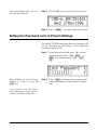
Setting the Password Lock to Protect Settings .......................................................6-5
Chapter 7
History Functions
7-1
Setting and Viewing Advanced functions ..............................................................7-1
Time History ......................................................................................................7-2
Time History Data..............................................................................................7-4
Log .....................................................................................................................7-4
Interval History ..................................................................................................7-5
Exceedance.........................................................................................................7-8
Setting PassBy Functions.................................................................................7-11
Overload................................................................................................................7-13
Chapter 8
Parameters
8-1
Parameter Key Access Review ...............................................................................8-2
Entering and Exiting the Setup Menu ................................................................8-2
Locating Parameters...........................................................................................8-2
Changing Parameters — Enter, Modify.............................................................8-3
Error Messages:..................................................................................................8-4
Learning to Store and Retrieve Setup Memory ......................................................8-4
Storing a Setup ...................................................................................................8-5
Recalling a Setup ...............................................................................................8-6
Model 720 Setup Parameters ..................................................................................8-6
System (1-20) R U S ..........................................................................................8-7
Timer (21-27) U T..............................................................................................8-9
Lock (28-34) U L .............................................................................................8-10
Calibration (35-36) U C ...................................................................................8-11
Sound Level Meter (39-50) C ..........................................................................8-11
Dose (51-54) E .................................................................................................8-12
LN Statistical Levels (55-58) B .......................................................................8-13
Exceedance Levels (61-65) V ..........................................................................8-13
Exceedance History (66-68, 162).....................................................................8-14
Interval History (72-79) M...............................................................................8-15
Time History (80-87) H ...................................................................................8-16
Print Options (89-112) s...................................................................................8-17
Additional System Functions (159,162) ..........................................................8-19
Chapter 9
Memory Usage
9-1
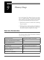
Determine Storable Data.........................................................................................9-1
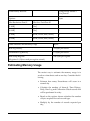
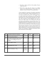
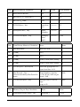
Estimating Memory Usage .....................................................................................9-2
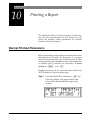
Chapter 10 Printing a Report
10-1
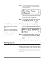
Normal Printout Parameters..................................................................................10-1
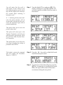
Printing Reports ....................................................................................................10-2
Appendix A Specifications
A-1
Type .......................................................................................................................A-2
Reference Direction ...............................................................................................A-2
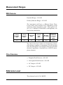
Measurement Ranges .............................................................................................A-3
RMS Detector ...................................................................................................A-3
Other Detectors .................................................................................................A-3
Reference Level .....................................................................................................A-3
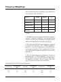
Frequency Weightings ...........................................................................................A-4
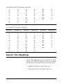
Detector Time Weightings.....................................................................................A-5
Effects of Temperature ..........................................................................................A-6
Effects of Humidly.................................................................................................A-6
Limits of Temperature and Humidity ....................................................................A-6
Positioning of Instrument and Observer for Best Measurements ..........................A-6
AC and DC Outputs ...............................................................................................A-6
AC Output .........................................................................................................A-7
DC Output .........................................................................................................A-7
Reference Frequency .............................................................................................A-7
Stabilization Time..................................................................................................A-7
Microphone Electrical Impedance .........................................................................A-8
Functions Measured ...............................................................................................A-8
Data Storage...........................................................................................................A-8
Data Communications............................................................................................A-8
Digital Display .......................................................................................................A-9
Digital Display Resolution.....................................................................................A-9
Display Bargraph ...................................................................................................A-9
Real-time Clock/Calendar......................................................................................A-9
Run-time Clock......................................................................................................A-9
Standards Met ......................................................................................................A-10
Power Supply .......................................................................................................A-10
Dimensions/Weight (with Microphone, Preamplifier and Battery).....................A-10
Appendix B Serial Port Interface Remote Control
B-1
Model INT002 Interface Cable.............................................................................. B-2
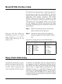
Daisy Chain Addressing ........................................................................................ B-2
Commands ............................................................................................................. B-3
History Oriented Commands ............................................................................ B-4
Mode Commands .............................................................................................. B-5
“Read” Variables............................................................................................... B-6
Other Read Commands ................................................................................... B-12
Group Read Programming ................................................................................... B-12
Querying and Setting Parameters ........................................................................ B-13
Querying Parameters....................................................................................... B-14
Setting Parameters........................................................................................... B-15
Option Parameters ...................................................................................... B-15
Numeric Parameters ................................................................................... B-16
Character String Parameters....................................................................... B-16
Template Parameters .................................................................................. B-16
Parameter List ...................................................................................................... B-18
Histogram Reports .......................................................................................... B-21
Tailored Report .......................................................................................... B-21
Miscellaneous............................................................................................. B-22
Error Checking I/O.......................................................................................... B-23
History Records ................................................................................................... B-25
Types of History......................................................................................... B-25
Advance...................................................................................................... B-26
Backup........................................................................................................ B-26
Find............................................................................................................. B-26
History Data Variables......................................................................................... B-26
Exceedance History Variables ........................................................................ B-26
Interval History Variables ............................................................................... B-27
Run Log Variables .......................................................................................... B-29
Calibration History Variables ......................................................................... B-29
Time History Variables ................................................................................... B-29
Histogram Table Variables ............................................................................. B-30
Print Commands .................................................................................................. B-31
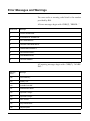
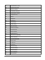
Error Messages and Warnings ............................................................................. B-32
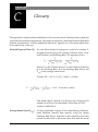
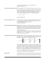
Appendix C Glossary
C-1
Appendix D Warranty/Customer Satisfaction
2-1
CHAPTER
1
Introduction
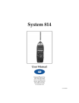
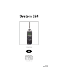
Welcome to the Larson•Davis Model 720. Your new
hand held Model 720 from Larson•Davis is a combination Type 2 precision integrating sound level meter and
a statistical data logger that exceeds all worldwide
accuracy requirements for the measurement of noise.
The Model 720 measures sound with the ease of operation of a “point and shoot” sound level meter. The latest advances in surface mount technology, prepolarized electret microphone, and internal firmware
have been combined in a rugged, lightweight yet
extremely versatile unit.
Many sound level meters in the market can create significant measurement errors because of their limited
dynamic range, pulse range, and crest factor. The
Model 720 does not have these limitations.
Furthermore, its internal firmware is designed to
accommodate changing regulations and to overcome
sound measurement problems. While the Model 720 is
the size of a dosimeter, it may also be used as an environmental noise monitor offering features which will
ensure quality measurements for many years.
We invite you to read this manual to get the most out
of your new Larson•Davis sound level meter.
6/7/05
Introduction
1-1
About This Manual
This manual has 10 chapters and 3 appendices covering the following topics:
• Chapter 1 - Introduction: Overview of this user manual and the Model 720’s functions and measurement capabilities.
• Chapter 2 - Overview to Model 720: Understanding
the keyboard and screen, turning the instrument on
and off, and checking the battery voltage.
• Chapter 3 - Calibration: Using a reference to calibrate
the instrument and its importance.
• Chapter 4 - Quick Start: Setting parameters, using
function keys, and using numbers and other characters.
• Chapter 5 - Performing a Measurement / Reading the
Data: taking a measurement and becoming familiar
with the function keys.
• Chapter 6 - Timed Measurement: Using the timer for
unattended readings, setting additional parameters, and using the password lock.
• Chapter 7 - History Functions: Setting parameters for
exceedance levels and history settings, interval and
time history settings, and daily history.
• Chapter 8 - Parameters: A complete listing of all
parameter items and an explanation of their basic
functions.
• Chapter 9 - Memory Usage: Sizing parameter needs to
insure adequate memory for any given measurement.
• Chapter 10 - Printing a Report: Turning gathered data
into a printed report.
1-2
Model 720 User Manual
6/7/05
• Appendix A - Specifications: A listing of acoustic,
electronic, environmental, and physical characteristics of the Model 720.
• Appendix B - Model 720 Serial Port Interface Remote
Control: Setting interface commands with their syntax.
• Appendix C - Glossary: Definitions of key terms and
concepts used commonly in the sound industry.
• Appendix D - Index: Alphabetical listing of all major
components of this manual.
About This Chapter
Specifically, this introductory chapter covers the following topics:
• Formatting Conventions: Explanation of the fonts
and other formatting conventions used in this manual.
• Model 720 Features: A listing of the featured characteristic, and capabilities of the Model 720.
• Model 720 Components: Description and diagrams
of the Model 720 external parts.
• Getting Started: Instructions for unpacking, a listing of accessories and optional equipment and initial setup.
Formatting Conventions
This manual uses the following formatting conventions:
6/7/05
Introduction
1-3
Functions accessed by pressing a key on the Model 720
keypad are shown with an icon, for example:
Press e and then press c
In step-by-step directions, the process (what you do) is
shown in the left column, and the rationale (why you
do it) with other cautions and comments are shown in
the right column.
Follow these steps to access the parameters using
numeric values:
Notice that the flashing (f) has been
replaced by a flashing (n) indicating
the numeric key access. The flashing
parenthesis, indicate this field is
ready to receive numeric input.
Step 1
To access parameters using numeric values,
press m.
Entering 0 before the new number
will remove any prior parameter settings.
Step 2
Press 0 and then 6. The number 6 is assigned
to the Current Time parameter:
Especially important information is shown in italics,
for example:
To access items 48-50, Overall Exchange Rate,
Overall Threshold, Overall Criterion, press the d
key.
Features
The Larson•Davis Model 720 meets the requirements
of the American National Standards Institute (ANSI)
S1.4, International Electrotechnical Commission (IEC)
651, and 804-1985 standards for Type 2 accuracy and
offers the following features:
1-4
Model 720 User Manual
6/7/05
• Dynamic range of more than 100 dB for error free
measurements.
• Impulse measuring range greater than 100 dB.
• Standard microphone allows measurements typically between 30 and 140 dBA in one range.
• Multiple detectors provide simultaneous RMS and
PEAK measurements.
•
Leq integrated level (duration ranging from 1 second to 99 hours, manually controlled).
• Measures FAST, SLOW, Unweighted PEAK,
Weighted PEAK, Impulse, Leq, LDOD, LOSHA,
Dose, Projected Dose, TWA, Sel (Lae), Lmax, Lmin,
four user-defined Ln’s, and more.
• User selectable dose exchange rate, criterion,
threshold, and reference duration.
• Measures and stores more than 40,000 different
DOSE combinations in a single measurement.
Allows comparisons of different DOSE standards
using the same data.
• Complete data logging capabilities with 64 Kobe
standard memory.
• Time history sampling periods are user selectable
from 1 second up to one sample every 255 seconds.
• Quartz clock/calendar system for data annotation.
• Calibration from front panel (using an appropriate
calibration source).
• Easy one step reset of measurement.
• Battery level indication.
• Standard 9V internal alkaline battery life of more
than 16 hours (or external power using L•D cable #
CBL035 for longer measurements).
6/7/05
Introduction
1-5
• RS-232 computer interface standard. All functions
fully programmable. Comes complete with PC
SWW_SLM_UTIL software for data retrieval and
translate binary files to ASCII format. Other PC
software also available.
• Large, two line, 32 character, high contrast LCD display.
• Small [20 x 7.5 x 2.5 cm HWD (8 x 3 x 1")] and without the nose cone [15 x 7.5 x 2.5 cm HWD (6 x 3 x
1")] and lightweight, 326 g (11 oz.), including microphone and battery.
• Rugged ABS case with EMI and RFI protection.
• Environmental enclosures available for system
security and protection from inclement weather
conditions.
• Durable membrane keypad.
• Two-year warranty (see warranty statement on the
copyright page at the front of this manual).
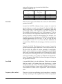
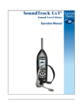
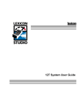
Model 720 Components
A layout of the Model 720 is shown below
1-6
Model 720 User Manual
6/7/05
Microphone
Windscreen
LCD Display
LARSON•DAVIS
MODEL 720
Modify
AC/DC Out
7
TIME
LEQ
TIMER
SEL
CAL
SLM
L MIN
L MAX
SHIFT
LOCK
EXCD
4
1
Cancel
OFF
ON
0
STR
PRINT
8
9
TAKT
TWA
LDL
DOSE
5
6
UWPK
PEAK
2
BATT
LN
Nose Cone
3
MEM
INTV
LOG
HIST
.
Enter
RCL
SETUP
RESET
R/S
Keypad
TYPE 2 INTEGRATING SOUND LEVEL METER
Serial Interface Port
:
6/7/05
Introduction
1-7
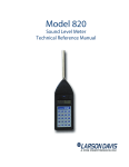
Figure 0-1 Model 720. The Model 720 is a convenient
hand-held sound level meter with a simple user
interface.
As can be seen, the standard Model 720 includes the
following:
• Model PRM789 3/8 inch preamplifier. The preamplifier cable may be looped inside the provided
nose cone when the meter is used as a hand held.
• A two-line, 32-character, high-contrast LCD display.
Keep clean and protect from condensing moisture and water. Rain
droplets or other foreign matter on
the diaphragm may alter the microphones’s response. Please use a
windscreen whenever possible.
• Model M1, 3/8 inch prepolarized microphone. The
microphone is rugged and reliable but the Model
720 should be kept in its protective case when not
in use. Avoid unnecessary shock (Although an L•D
microphone can survive being dropped, it should
be handled with care).
• A 20-key membrane keypad.
• Model 720 precision hand-held Sound Level Meter
with removable nose cone. Powered internally by 9
volt cell, or by an external battery or AC/DC
adapter.
• WS002 3/8 inch windscreen.
• An AC/DC mini phone connector with pinout
shown on page 4-7.
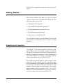
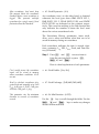
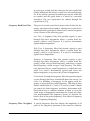
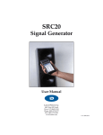
A 5-pin cable connector with the pinout shown in figure Figure 1-2 (note that it may be used to access external power):
Using cable CBL038 or INT002 and
related software, the 5-pin connector
is used both for external power and
for the remote interface.
1-8
Figure 0-2 External 5-pin Serial Communications
Connector Pinout.
Model 720 User Manual
6/7/05
Pin 2: TXD Transmitted Data from 720
Pin 3: RXD Received Data to 720
Pin 4: Ext Batt External Battery to 720
3
2
4
1
5
Pin 5: DTR Data Terminal Ready from 720
Pin 1: GND Digital Signal Ground
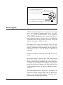
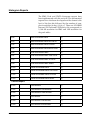
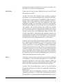
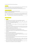
Block Diagram
All the standard functions of a precision sound level
meter are provided: instantaneous level, Leq, SEL,
Lmax, Lmin, Dose, projected dose, etc. In addition,
many valuable parameters can be stored: time history
interval data such as Ln’s and Leq, etc. Level calibration
is performed in a few key strokes, and every change or
check is entered in a calibration log.
The Model 720’s large data memory frees the user
from the concern of data loss caused by memory limitations. Furthermore, measurements can be printed or
transmitted at up to 19.2 K baud via RS-232 for
archiving.
Despite its numerous functions, the Model 720 is easy
to use.
Annotated displays indicate units and measurement
mode. The single setup menu lets the user scroll
through and program parameters or use an index key
to modify specific information. Multiple measurement
setups can be stored in memory for later recall. And of
course, complete setups can also be transferred from a
computer.
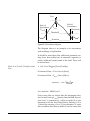
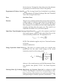
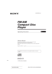
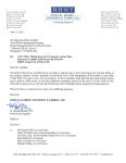
The block diagram below shows how the Model 720
sound level meter merges state-of-the-art analog circuitry, a powerful microcomputer controller and a
large amount of usable data memory.
6/7/05
Introduction
1-9
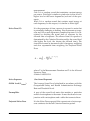
The signal from the microphone/preamplifier is input
directly to the linear peak detector and, through the
selected A- or C-weighting filter, to the root-meansquare (RMS) and weighted peak detectors. Analog to
digital conversion is performed maintaining a full 110
dB range for the rms signal. The numeric data is then
analyzed by the Model 720’s dedicated digital processor.
712/720 Block Diagram
Microphone
A
Filter
40
C
Filter
42
LCD
RMS 39
Slow, Fast, Impl
Peak 1
Peak 2
Keypad
Clock
Timer
Microprocessor
A:D
Internal
9V Battery
Power
Supply
RAM
64K
Flash
128K
5-pin
Connector
Weighted
AC/DC Output
N Indicates parameter number
0 dB
Flat
41
20 dB
Figure 0-3 Block Diagram.
With system programming residing in PROMs (programmable read-only memory), upgrade or future
changes in regulations can easily be accommodated.
Measurement modes are selected and shown in informative screens on the 32 character liquid crystal diode
(LCD) display. The custom keypad provides direct
access to the needed data or setup item. An accurate
built-in Quartz clock/calendar and timer are ideal for
unattended measurements and time stamping of
events.
The 64 KB memory can be used to store time, exceedance or interval data as selected by the user. All can be
printed or transferred to an external computer via the
serial port, even during data gathering. L•D PC-compatible software employs a binary data dump method
for even faster data transfer. External battery or DC
1-10
Model 720 User Manual
6/7/05
power may be supplied through the same five pin connector.
Getting Started
This section outlines the steps you need to follow
when you first receive and unpack the Model 720. The
following topics are covered:
• Unpacking and Inspection.
• Accessories and Optional Equipment.
• Connecting Internal or External Power.
• Environmental Considerations.
• Preparing to use the Model 720.
You will then be ready to use the Model 720 for actual
measurements (as described later in Chapter 4 of this
manual).
Unpacking and Inspection
Your Model 720 has been shipped in protective packaging. Please verify the package contents with the following list (Accessories and Optional Equipment) and
retain the shipping containers for safe shipment at a
future date. Report any damage or shortage immediately to Larson•Davis, Inc. at (801) 375-0177.
If you have not already done so, please record, at the
beginning of this manual (see the copyright page),
your instrument’s serial number (located on the label
on the back of the Model 720), the microphone serial
number (located inside the microphone), the preamp
serial number, and the purchase date. You will be
asked to give this information in any future communications you may have with Larson•Davis, Inc.
6/7/05
Introduction
1-11
Accessories
The Model 720 is delivered with the following standard
accessories:
• The standard Model 720 Precision Sound Level
Meter including a Model M1 3/8" air condenser
microphone and Model 789 preamplifier.
A good quality alkaline cell should
provide more than 16 hours of Model
720 operation. Since most rechargeable cells have less capacity, expect
shorter use.
• Alkaline battery, 9 volts (IEC GLR61 or NEDA/
ANSI 1604A).
Wind noise can adversely affect measurements. Using the windscreen on
the microphone reduces wind noise
and protects the element from dust
and bumps.
• WS002 a 3/8 inch mini-windscreen.
• User manual.
• Soft belt pouch (L•D part # CCS009).
• SWW_SLM_UTIL software.
Utility software package allowing data retrieval and
translation of binary files, generated by the Model 720,
to ASCII File Format via RS-232 connection, and is
capable of editing and storing instrument setup
parameter to the PC, or loaded directly to sound level
meter.
Optional Equipment
The following optional equipment is also available:
• CBL033: Printer cable for direct printout to serial
printer, 6 feet.
• CBL034: Connects Model 720 and un-wired cable
end (4-conductor shielded).
• CBL035: Connects Model 720 and customer supplied external battery.
• CBL038: Connects Model 720 to battery and RS232
port of most laptop computers. CBL077 extension
cable or similar recommended if longer length
required.
1-12
Model 720 User Manual
6/7/05
• CBL042 AC/DC output of the Model 720 to RCA/
BNC connectors.
• INT002: RS-232 cable level converter for data transfer to PC. Requires 9 V battery or external AC
power supply (P5001 included). Note that external
supply will also power the Model 720.
• PSA001: AC/DC power adapter, 115 Vac to 9 Vdc,
50-60 Hz for use with INT002.
• CCS002: Custom hard shell, airtight, watertight
case (13 1/2 X 12 7/8 X 6 in).
• CBL040: Similar to INT002 but allows one to “daisy
chain” an additional Model 720.
• PS002: AC/DC power adapter, 220 Vac to 9Vdc, 5060 Hz for use with INT002.
• EPS012: Weatherproof fiberglass case with customcut foam interior and desiccant. Sealed signal cable
feedthrough. Features lock hasp and may be
chained through handle for security.
• EPS013: Same as EPS012 but with 8 Ah, 12 Volt
rechargeable battery BAT004. Provides 1 week
operation in normal conditions. Includes CBL038
and battery charger.
6/7/05
Introduction
1-13
WS001*
WS005 Windscreen
with birdspikes
2530
2520
2575
2570
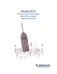
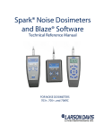
Note Figure 1-4 or call Larson•Davis for additional
information on these and other accessories.
Rainhat with
electrostatic actuator
WS005
2551
2560
2541
ADP008
2559
2540
1/2-inch Microphone
PRM2101
ADP011
720 SYSTEM
2106/7/8
EPS013 Environmental Case w/ Battery
PRM828*
Note: Those items marked with "*"
are standard included accessories.
EPS012 Environmental Case
Software
SWW SLM UTIL*
SWW SLM LINK
SWW ENV
SWW REM
SWW NMS
SWW ACS
EXCXXX
(20’ Max)
(20’)
CBL042 (6’)
AC Out (black)
DC Out (red)
LARSON DAVIS
Larson
Davis
WEB Page
720 SLM
Modify
7
TIME
L EQ
CCS009
Soft Case*
4 Conductor
Shielded
TIMER
SEL
8
9
L DN
T.A.
LDL
DOSE
4
5
6
CAL
SLM
LMIN
LMAX
UWPK
PEAK
BATT
LN
1
2
3
SHIFT
LOCK
EXCD
MEM
INTV
LOG
HIST
Cancel
0
.
Enter
STR
PRINT
RCL
SETUP
RESET
R/S
CBL009-020 (820 OPT01 required)
(1.5’)
TYPE 1 INTEGRATING SOUND LEVEL METER
Battery (powers 2101 heater and EA)
INT002 (12’)
CBL034 (6’)
PSA001
To next SLM
Battery to
power 720
CBL035 (4’)
Desktop Computer
CBL040 (12’)
PSA001
(alligator clips)
PSA005 AC/DC Adaptor
CBL116 (1.5’)
Battery
CBL077 (6’, optional)
(2’)
Laptop Computer
CBL033 (6’)
CBL116 (1.5’)
CBL077 (6’, optional)
Serial Printer
(2’)
Figure 0-4 720 System Diagram
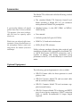
Battery Installation
To insert the 9 volt battery in the Model 820, remove
the battery cover at the lower left side of the instrument by sliding it out as shown in Figure 0-5 .
1-14
Model 720 User Manual
6/7/05
Figure 0-5 Remove Battery
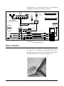
With the battery door removed, drop the battery into
the opening in the case as shown in Figure 0-6 , making certain that the battery is aligned with the positive
and negative electrodes as shown on the graphic inside
the battery compartment.
Figure 0-6 Inserting Battery
Internal battery life is approximately 16 hours. (Refer
to the description in Chapter 2 of this manual for additional battery information.)
The cable CBL116 SLN serial connectivity kit, which
allows connection of the 820 to a PC or modem, provides the connection of an external power adaptor
such as the PSA017 or similar
Alternatively, you may use an external power source via pin
1(GND) and pin 4(+) of the 5-pin connector. To do this,
order cable #CBL035 from Larson Davis. The Model 820
accepts 7-16 Vdc @ 30 mA and is internally fused at 0.5 A.
• An internal battery with a full charge will retain
memory for 3 months with the instrument off.
6/7/05
Introduction
1-15
Caution: Weak batteries should
always be replaced. Discharged batteries will cause memory loss and
may leak and damage the Model 720.
Always turn the instrument off and
disconnect external peripherals
before removing the internal battery.
Failure to do so may cause data loss.
Do not press ON while there is no
battery in the SLM.
• The instrument will turn off when the usable battery capacity drops to 10%. This will leave approximately 1 month of memory retention.
Before turning off, four low battery messages will
appear, one every 16 seconds. After 64 seconds the
instrument turns itself off.
• With the battery removed, a capacitor will retain
memory for several minutes (during battery
change).
• The Model 720 will instantly turn off should the
voltage drop to less then about 4.4 V. An error message will be displayed at next power-up: “Warning
Power Failure”.
Once the battery is installed, the Model 720 is ready for
use.
Environmental Considerations
The Model 720 sound level meter can be both used and
stored in a wide range of temperature, free of moisture
and non-condensing humidity conditions. Some precautions should be taken. For example, allow the
Model 720 ample time to adjust to abrupt temperature
changes. Condensation may form inside a cold Model
720 if it is brought into a warm room or vehicle and
may persist long after the outside case has adjusted to
the ambient temperature.
Also, temperatures inside closed vehicles can reach
excessive levels. Therefore, do not leave the instrument in
direct sunlight in a vehicle. A simple safeguard is to keep
the instrument inside a sealed foam insulated case or
bag with desiccant silica gel, available at photographic
equipment stores or from Larson•Davis.
1-16
Model 720 User Manual
6/7/05
CHAPTER
2
Overview to Model 720
Once your Model 720 is unpacked and connected to a
battery (or external power supply), you can turn it on
and take simple measurements. In this chapter, we discuss the following:
• Understanding the Model 720 Keypad.
• Understanding the Model 720 Screen.
• Getting to Know Screen Symbols.
• Turning on the Model 720.
• Checking the Battery Voltage.
• Turning off the Model 720.
6/7/05
Overview to Model 720
2-1
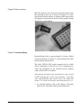
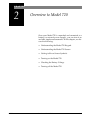
Understanding the Model 720 Keypad
The keypad for the Model 720 has 20 keys as seen in
the following figure (Figure 2-1):
LARSON•DAVIS
MODEL 720
Modify
7
8
TIME
LEQ
TIMER
SEL
CAL
SLM
L MIN
L MAX
SHIFT
LOCK
EXCD
4
OFF
ON
9
LDL
DOSE
5
1
Cancel
TAKT
TWA
UWPK
PEAK
6
BATT
LN
2
0
STR
PRINT
3
MEM
INTV
LOG
HIST
.
Enter
RCL
SETUP
RESET
R/S
TYPE 2 INTEGRATING SOUND LEVEL METER
Figure 0-1 Model 720 Keypad.
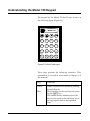
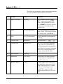
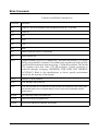
These keys perform the following functions. (This
information is covered in more detail in chapter 4, of
this manual.)
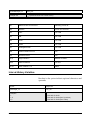
Keys
Functions
White
White functions are accessed by pushing
buttons directly.
Blue functions are accessed by first pressing the U key.
The smaller letters/numbers above the
keys are accessed by the adjoining key at
the appropriate time to be explained
later.
Blue
2-2
Model 720 User Manual
6/7/05
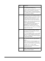
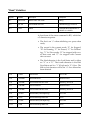
6/7/05
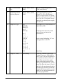
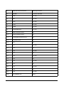
Keys
Functions
O
c
ON: Turns on the Model 720.
CANCEL: When the Model 720 is on, this
button serves to return to a previous
menu, or “Cancel” the present function.
OFF: SHIFT OFF turns off the Model 720
after it has been stopped.
s
Print: Access to a list of reports scrolled
through the display; a key name is indicated for each one. If there is a “+” following the key name then the options
function will be invoked after selecting
that key, otherwise the particular report
will be printed immediately.
STR: A permanent storage register for
parameters and calibration data in
EEPROM type memory that is not lost
when all power is lost. There are 2 RAM
registers to store data.
R
SETUP: Enables the setting of desired
parameters, each accessed by using the
up and down arrow keys.
RCL: The EEPROM register and the RAM
register may be recalled by pressing the
RCL key, scrolling to the desired register
and pressing ENTER.
S
e
R/S: This key starts and stops measurements
RESET: Restarts a measurement by erasing the values just measured.This function can be used whether a measurement
is in the “run” or “stop” mode.
ENTER: used to enter new parameters
selected by the user.
U
SHIFT: Allows access to the blue letter
functions on the keypad.
Overview to Model 720
2-3
2-4
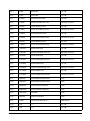
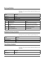
Keys
Functions
L
EXCD: The Exceedance History is a
record of noise events which exceed a
programmed level for a time greater than
a programmed minimum time period.
See parameters 66-70.
LOCK: The lock functions protect instrument data and configuration.The level of
security is configured in Setup.
M
INTV: The Interval History provides a
history of a number of measurements
values for a moderate size time interval,
1 minute to larger than 99 hours in one
minute or greater steps. It is programmed by parameters 72-79.
MEM: Memory use in percent, bytes free
and total byte available are provided as
well as a count of all of the History
Records stored in memory.
H
HIST: The Time History function is a
record of short interval Leq reading and
optionally, a Peak, UWPK, or Lmax reading. The interval can vary from 1 second
to 255 sec. History period is set by
parameters 83-84.
LOG: The Run/Stop Log is a time record
of all the actions which start or stop the
data taking process of the Model 720.
C
CAL: Calibration information and control. Initially, in the CAL-a display, the
current calibration offset is displayed
with a flashing prompt to press either the
UP arrow key to check the calibration or
press the d key to change the calibration.
SLM: The Sound Level Meter function
displays the current Sound Pressure
Level (SPL) while the instrument is in the
Run Mode or the SPL at the instant it was
last stopped.
Model 720 User Manual
6/7/05
6/7/05
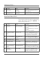
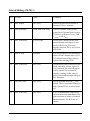
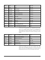
Keys
Functions
V
LMAX: The maximum SPL, or Lmax, is the
largest sampled SPL for the overall measurement period, displayed with the date
and time of its occurrence. Two additional screens, accessed by pressing the
left or right arrows, show the number of
times the SPL exceeded two fixed levels.
LMIN: The minimum SPL, or Lmin, is the
lowest sampled SPL for the overall measurement.
K
PEAK: The highest weighted Peak Detector output level, Lpk. Date and time of the
occurrence of the Lpk is also shown. The
number of times the weighted peak level
exceeds a programmed threshold is also
counted and displayed (-b window).
UWPK: The highest UnWeighted Peak
Detector output level, LUWPK. The date
and time of the occurrence of the Luwpk
is also shown. The number of times the
weighted peak level exceeds a programmed threshold is also counted and
displayed (-b window).
B
Ln: The LN values represent the SPL
exceeded n% of the run time. All values
from 1% to 99% are available, two of four
are displayed at a time and can be
changed even while running.
BATT: This key gives the percentage of
power remaining in the 9 V battery, or
external supply.
BATT-b: Gives Model 720 revision number and date.
Overview to Model 720
2-5
2-6
Keys
Functions
T
LEQ: The Equivalent Level or Leq is a
Time Weighted Average based on an
exchange rate of 3dB (true energy measure) with no threshold.
TIME: The date and time of last reset or
measurement start are available from the
Time-a display. The current date and
time are shown with the Time-b display.
t
SEL: The Single Event Level or Sound
Exposure Level is an energy reading in
decibels. It is the TWA level plus 10 times
the log of measurement time in seconds.
SEL-b: Gives exposure in Pa2H which is a
linear representation of energy.
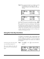
TIMER: The ability to take a measurement at a specific time and date is available, thus permitting unattended
measurements, i.e. one or two measurements/day between two dates or a single
block measurement from a start date and
time to a stop date and time.
WA
TAKT: The German Takt Maximal Levels.
TWA: Shows the overall TWA and Run
Time.
E
DOSE: The Dose and Projected Dose
sound exposure percentages are displayed in these screens. Parameters #4851 control the Dose measurement.
LDL: Logged Dated Logic allows the user
to recalculate TWA, SEL, DOSE and Projected Dose using new Exchange Rate,
Threshold, and Criterion parameters
during or after a measurement.
Model 720 User Manual
6/7/05
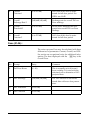
Keys
Functions
ud
lr
m
Arrows: Up, Down, Left and Right arrows
are used to change fields, to modify
information within a given field and can
be used in conjunction with other keys to
allow other functions.
Modify: Prepares the field for changes
while in setup.
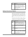
Getting to Know Screen Symbols
Symbols basic to the Model 720 are included below.
These are generally found to the right of the screen.
The Operating Mode Indicator, upper right character,
indicates whether data is being accumulated or not
and has the modes indicated by the first four examples.
The Keyboard Status Indicator displays which key
functions are active. The lower four modes are possible
and appear in the lower right corner or the display.
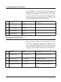
Symbol
Functionality
SsS
(flashing upper case to lower case) Model 720 is stabilizing upon warm-up
(10-45 sec.), or SETUP weighting (8s), or
bias voltage (30s) change in stop mode.
Stop mode - no data is being taken.
Run mode
OVLD
6/7/05
Overload - These letters in succession
occur alternately with the stick figure
with 8 second intervals when an overload has occurred.
Overview to Model 720
2-7
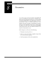
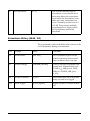
Symbol
Functionality
f
(flashing) - Indicates that the function
keys (Lmin, Dose, etc.) are used for different purpose in the current function.
n
Indicates that numeric key input mode is
active.
S12
U key active (secondary function in blue
lettering).
SrS
If the Model 720 is still stabilizing upon
warm-up and the R/S (Run) button is
pushed, (r) will flash alternately with (S).
Understanding the Model 720 Screen
The operating screen for the Model 720 has several
fields which vary according to the keys pressed on the
keypad.
The most pertinent information is generally at the top
and center to left and instructions are generally on the
bottom center to left. Several characters are consistent
in their appearance. We will now turn the Model 720
on and examine a variety of possible screens.
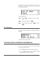
Turning On the Model 720
Three successive displays will appear
while the meter stabilizes for 10-45
seconds. The first display has copyright information and appears only 1
to 2 seconds
2-8
Step 1
Press O to power the Model 720 and initiate a
self test:
M
Model 720 User Manual
S
6/7/05
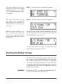
The next display automatically appears.
The second display shows the production date and the serial number
uniquely assigned to your Model
720. This message appears for only 1
or 2 seconds.
Step 2
This screen will remain until the
user inputs other commands.The
flashing uppercase (S) indicates system initiation and will continue 1045 seconds.
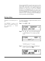
Step 3
When the system initiation is complete, a stick figure in the upper right
corner of the display will appear
seated indicating the Model 720 is in
STOP mode.
The third screen appears almost immediately showing
the title information for the current or last reading and
is programmable by the operator.
s
The third screen automatically appears:
S
At this point, you can change the parameters and
begin taking actual measurements.
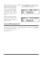
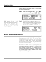
Checking the Battery Voltage
The Model 720 continuously monitors its battery voltage to ensure accurate measurements. It has a battery
life of about sixteen hours. It will turn off automatically when the voltage falls below 5.7 volts. Therefore
you should verify that the remaining battery capacity
is sufficient before you make an especially critical or
lengthy measurement.
WARNING!
6/7/05
Do not press the B key during a measurement since it
will pause the measurement while pressed.
Overview to Model 720
2-9
Remember, pushing a button can
produce small low-level noises which
can affect your readings. In addition,
the Model 720 momentarily pauses
the current measurement whenever
a key is pressed (in order to interpret
the keyboard event). Therefore,
where possible, do not press the B
key during a valid event you wish to
measure.
Step 1
To manually check battery voltage, simply
press the UB keys. Information similar to the following will display
The first screen shows the percentage
of power left in the battery, the internal power source, “INT”; the second
display indicates external power is
being used, “EXTV.”
Turning Off the Model 720
The instrument will not allow itself
to be turned off until in (Stop) mode.
This feature will insure that no
important data is lost.
2-10
To turn off the Model 720, simply press the UO
key.
Model 720 User Manual
6/7/05
CHAPTER
3
Calibration
Because of variation in microphone sensitivities, a
sound level meter must be calibrated to a reference
sound level for accurate measurements. This is easily
performed with the Model 720. You will need a calibrator with an appropriate adapter for the Model 720
microphone, such as the Larson•Davis CAL150. This
L•D calibrator outputs 114 dB, or 94 dB, with respect
to 20 µPa, and at a frequency of 1000 Hz. At this frequency, the relative response for A and C weightings
is the same.
NOTE: A precision calibrator is not necessary for this part of the
tutorial, but you should make it a regular practice to perform an
instrument calibration before and after you take actual measurements in the field. However, you do not have to recalibrate the
Model 720 when you change the settings.
Please note that if you use a calibrator which uses
another frequency some corrections may be required
depending on the weighting. The output level and the
frequency of your calibrator should be listed on its
label. Use this level with specific environmental and
weighting corrections to calibrate the Model 720 level.
6/7/05
Calibration
3-1
Calibrating the Model 720
To begin the calibration process check or insert the
new calibration level given in parameter 35.
The Larson•Davis Model CAL150
calibrator outputs 114 dB or 94 dB
re. 20 µPa. Note that the Model 720
automatically uses the C-weighting
while calibrating. This ensures a correct reading at typical calibration
frequencies of 250 Hz to 1 kHz.
Refer to the specific instructions
accompanying your calibrator for
accomplishing this step.
3-2
Step 1
To do this press R, m, 3 and 5, then
e. The following screen will appear:
Step 2
Press m, then enter the “SPL” value of
your calibrator (if other than [114.0]), including any corrections for pressure, etc.
Step 3
The next setup item allows entry of the calibrator serial number, for record keeping purposes. Press the d, or R, m, 3 and 6,
and e.Press m to change the serial
number, enter the correct numbers and press
e.
Step 4
Seat the microphone fully in the calibrator
cavity. If possible both units should be at the
same temperature and stationary so that
hand vibrations are not transmitted to the
SLM.
Step 5
Press c to exit calibration setup. Then,
activate the calibrator by pressing the button
on its side.
Model 720 User Manual
6/7/05
Pressing the u will check calibration, pressing the d will change
it.
Step 6
Press the U and C on the Model 720.
This display indicates the current sensitivity
off set and will be blinking between two settings:
In this screen, an error message may
initially prompt for a reset. The difference between the current and the
last calibration is 0.0 db. If the level
is not stable enough for proper calibration, the Model 720 will exit the
calibration mode without changing
its calibration level. The “c” indicates the instrument is calibrating.
Step 7
Pressing the d key will initiate a calibration change. Do that now:
Step 8
To Reset the Model 720 for re-calibration,
press U and S.
Step 9
Press e. Reset is complete and the
instrument will return to the calibration
mode.
The Model 720 will wait until the
reading is stable (indicator is
SsSsSs...., then adjust the offset for
the proper reading CcCcCc..... An
improper calibration offset (for
instance, something greater than
34.0 dB) may indicate that the calibration tone was shut off before calibration was completed. You may
repeat the previous steps or perform
a Cal check.
The display will ask if you want to
“Reset ALL Data?” You do.
Step 10 To leave the calibration mode, press c.
6/7/05
Calibration
3-3
3-4
Model 720 User Manual
6/7/05
CHAPTER
4
Quick Start
Before running a simple measurement it is important
to set a few parameters to meet your needs and
become familiar with related functions. In this chapter
we will discuss these items:
• Setting parameters using R, m, and
• Using numbers and other characters
e
• Setting Time, Date, and Day parameters
Setting Parameters Using Function Keys
The Parameter fields can be accessed in several ways:
• By entering numbers assigned to each parameter
(the numbers are located above the keys on the keypad and are discussed later in the chapter)
• By scrolling up or down using the u or d keys
• By using any white or blue function keys
Follow these steps to access the parameters using
numeric values:
A complete list of parameters and
their assigned numbers is found in
Chapter 8.
6/7/05
Step 1
With the Model 720 on, press R and the
following screen appears:
Quick Start
4-1
Notice that the flashing (f) has been
replaced by a flashing (n) indicating
the numeric key access. The flashing
parenthesis, indicate this field is
ready to receive numeric input.
Step 2
To access parameters using numeric values,
press m:
Entering 0 before the new number
will remove any prior parameter settings.
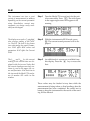
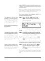
Step 3
To access the Current Time, press 0 and then
6. The number 6 is assigned to the Current
Time parameter:
The third way to access Current
Time parameter, press R
UT. Remember, press m
to change or correct the field and
press e.
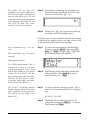
Step 4
Press m to prepare the screen for changes
in the Current Time. Notice the flashing (f)
changes to (n).
Step 5
Using numeric keys make changes and press
e, or if the time is correct, just press
e.
Step 6
To exit the setup mode, press
c.
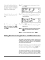
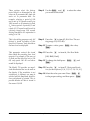
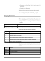
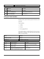
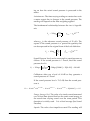
Setting Parameters Using Numbers and Other Characters
The Model 720 has the ability to show 3 lines for your
Company Name and one line for the Measurement
Title which is used on the reports. These parameters
are entered from the keyboard.
Through the keyboard, you can enter all of the capital
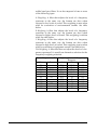
letters from A to Z, the digits 0 to 9, and some punctuation characters. There are three levels of U functions when in the “Alpha Parameter Modify Mode.”
The charts below (Figures 4-1 to 4-4), show the characters that are available. They are listed according to the
number of times you consecutively press the U
key. The shift indicator in the lower right corner of the
4-2
Model 720 User Manual
6/7/05
instrument’s display will show the number of times
the U key has been pressed by showing the letter n and S, then 2 and 3 respectively for 0 to 3 presses.
This panel is available without
pressing the shift key, or the equivalent of 0 presses.
Figure 0-1 Standard Alpha-Numeric Keyboard Layout
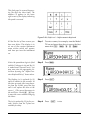
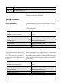
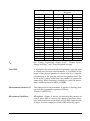
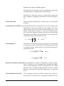
This panel is accessed by pressing
the shift key one time. The (S) will
appear in the lower right corner of
the display indicating this panel is
accessed.
Figure 0-2 S Shift Level-1 Alpha Numeric Keyboard
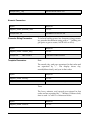
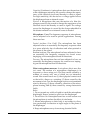
This panel is accessed by pressing
the shift key two times. The number
(2) appears in the lower right corner
of the display indicating this panel is
accessed.
Figure 0-3 2 Shift Level - 2 Alpha-Numeric Keyboard
6/7/05
Quick Start
4-3
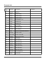
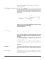
This final panel is accessed by pressing the shift key three times. The
number (3) appears in the lower
right corner of the display indicating
this panel is accessed.
Figure 0-4 3 Shift Level - 3 Alpha-numeric Keyboard
All but the last of these screens you
have seen before. This display is to
set one of four custom instrument
name screens which will appears
each time you turn the instrument
on.
Step 1
To enter a name, for example, turn the Model
720 on and press these keys to access the first
name field, R m 0 2 e:
Notice the parentheses begin to flash
and the (f) changes to (n) and the (L)
is underscored (Larson-Davis). You
may now enter the appropriate letters here by using the “Alpha Character Keyboard Entry” shown above.
Step 2
Press m.
The flashing (n) is replaced by (S)
and will remain for five seconds. At
this time you may select any character from the S-table, press that key
and it will replace the letter at the
cursor (_). The cursor then moves to
the next letter. Use the r l keys
to move the cursor without changing
the letters.
Step 3
Press U.
The (n) is replaced by (2) for five seconds. Letters from the 2-panel are
available for entry.
Step 4
4-4
_
Press
U
Model 720 User Manual
twice.
6/7/05
A (3) will appear for five seconds.
The letters from the 3-panel are
available for entry.
Step 5
Press U
three times,
Example: To enter the company name of Larson•Davis in the first line, follow these steps:
The display in Step 1 above will
appear.
a. To access the Name Display turn on the
meter. Press R m 02 e
If you change your mind about clearing the field, hit c to return to the
original title. Repeat a and b in Step
5 to return to this point.
b. Press m to place the cursor at the beginning or use the l oor r to position
the cursor.
Enter the (L) key, second from the
lower left. The cursor will automatically move to the next letter.
c. To clear the field, if necessary, press
U twice and the l key.
d. The letter (L) is on the S-field. Press
U.
Enter the (A) key.
Enter the (R,S,O) keys consecutively or one at a time.
e. The letter (A) is on the S-field. Press U
again.
Complete the rest of the entries in the
same fashion.
f. The (R,S,O) keys are in the 2-field.
Press U twice to access the 2-field.
g. To Clear the field, press U twice to
access the 2-chart and press the Clear key.
h. To replace a character with a Space, press
U twice to access the 2-field and press
the Space key.
Three lines are available for entry,
i.e. company address, telephone.
6/7/05
Step 6
When the first line is completed press the d
to go to the next field, the second line.
Step 7
Press m and select the appropriate chart
by pressing U and the desired character
key.
Step 8
When the second line is complete, press the
d to go to the next field, the third line, and
repeat the process.
Quick Start
4-5
The first and fourth lines will appear
on screen when the Model 720 is
turned on.
Step 9
The fourth line is for the Measurement Title.
Press the d key.
Step 10 To exit the setup mode, press
c
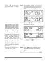
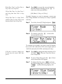
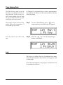
Setting Time, Date, and Day parameters
Once you have set the parameters, you can now enter
the correct time and date. The Model 720 has a 24 hour
(military time) clock where afternoon hours are
denoted by adding 12 hours, e.g. 3:45 p.m. = 15:45 hrs.
Modify this parameter as follows:
The current time is displayed. If it is
incorrect, enter the correct time.
Step 1
With the Model 720 on, press R UT:
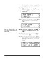
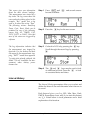
Step 2
Press the mkey and use the numeric
keys to enter correct time and then press
e:
The current date will appear. If it is
incorrect press m to access the field,
enter the correct date using the corresponding number keys and press
e.
Step 3
The Current Date is the next field. Press the
d to the next display:
If the day is incorrect press m
and r or l to the correct day. Press
e.
Step 4
The Day of the Week is in the next field. Press
d to access that field.
4-6
Step 5
To exit the setup mode, press
Model 720 User Manual
c.
6/7/05
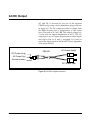
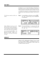
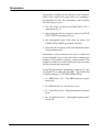
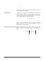
AC/DC Output
AC and DC is accessed by the use of the optional
CBL042 or by using a stereo miniphone plug as shown
in figure 4-5. The DC output provides a voltage from
the RMS detector that is proportional to the sound
level. The scale is 20.3 mV/dB. The output voltage is 03 volts with an output impedance of 600¾. The AC
output gives an AC signal proportional to input signal
and can be Flat or A and C weighted. It is used to
record the input signal to the Model 720 (see Appendix
A for more details).
CBL042
AC Output (black)
DC Output (ring)
AC Output (tip)
Ground (sleeve)
DC Output (red)
Figure 0-5 AC/DC Output Connector
6/7/05
Quick Start
4-7
4-8
Model 720 User Manual
6/7/05
CHAPTER
5
Performing a Measurement/
Reading the Data
With the basic parameters set and the instrument calibrated (as discussed in Chapters 3 and 4), you are
ready to take a measurement and examine the readings from the data collected.
Taking an actual measurement with the Model 720
only requires pressing the S or RUN/STOP key.
In this chapter we will:
• Take a measurement.
• Examine and briefly explain the function keys associated with the measurement, i.e. C V B
T W t E and M.
• Stopping the measurement.
Taking a Measurement
This section will address measurements and the information available during and after the measurement
has been taken. The most basic function of the Model
720 is to measure sound pressure. Follow these steps to
examine the SLM function key:
6/7/05
Performing a Measurement/Reading the Data
5-1
SLM
This instrument can store a great
variety of measurements in memory
depending on the current parameter
setup. Nevertheless, current measurements are always easily available from the keypad.
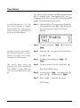
Step 1
Turn the Model 720 on and wait for the unit
to become stable. Press S. The stick figure
in the upper right corner will appear to be
running.
The display now reads a C-weighted,
slow average reading of 84.5 dBC
(re. 20 µPa). The level is also shown
on a semi-analog bar graph. Parameters 39-43 affect these values and
parameters 45-47 effect the Current
SLM.
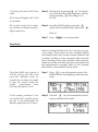
Step 2
With the instrument in RUN mode, press
C. The current sound pressure level is displayed:
The Lmin and Lmax for the current
reading at the current time are displayed in the first screen. Notice that
the current sound pressure level continues to read in the upper left corner and fluctuates. Note that even in
the stop mode the Model 720 continues to monitor SPL while in this
window.
Step 3
An additional six screens are available from
this display. Press the d key to access the
first:
****
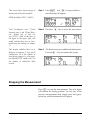
These values may be checked at any time while the
measurement is being taken, or final readings after the
measurement has been completed. Be careful not to
bump or drop the instrument as the results of the reading will be affected.
5-2
Model 720 User Manual
6/7/05
Step 4
Press the d key again for the second
screen. In this example the measurement has
been stopped. Notice the figure is at rest:
The Leq values are shown here to be
85.5 dB, C-weighted, the measurement ran for 3 minutes plus. Should
an Overload occur, one of four letters
(OVLD), would flash alternately
with the stick figure in the upper
right corner (see Chapter 7).
Step 5
Press the
The SEL level (using 3 dB exchange
rate) is 109.1 dB and the duration of
the measurement is given.
Step 6
Press the d
The Alarm can be set to begin a measurement at a designated time. The
“??:??” here indicates the next measurement has not been chosen. The
current internal temperature as measured by the Model 720 is shown in
the lower portion of the screen.
Step 7
The next screen addresses the Alarm time and
current temperature. Press the d key the
fifth screen will appear:
The Peak and Unweighted Peak are
displayed here. Note that the Model
720 is still taking a measurement
here, however in the stop or pause
mode the Model 720 continues to
display the detected values on the
upper right hand side of the screen.
The numbers on the left are the highest during the measurement and the
numbers on the right are the current
Peak and Unweighted Peak.
6/7/05
d
key for the third screen:
key for the fourth screen:
Performing a Measurement/Reading the Data
5-3
The Model 720 has been programmed to save power whenever it
can. Each time input is made this the
internal timer will start at 100 and
count downward. If not programmed
to do otherwise, the Model 720 will
turn itself off when this screen
reaches 0, just over two minutes.
Step 8
The property controlling the final screen in
this series is built into the Model 812 to conserve power. Press the d key.
0
Step 9
Pressing the d key again will scroll loop
you back to the SLM original screen.
Now that you are more familiar with the information
available in the displays above, lets take a closer look
at the parameters that affect these readings.
Slow: exponential avg: 1 sec constant
Step 1
To access these parameters turn the Model
720 on by pressing c. Next press R
m 3 9 e (Or press R, C), and
the following screen will appear:
Step 2
The Detector prompt has three possibilities
indicated above. Press mr to access
desired setting, and e
Step 3
To set the Frequency Weighting, press d to
item 40. You can choose either A or C weighting:
Fast; exponential avg: 1/8 second
constant.
Impl: impulse response.
For OSHA measurements, this is
normally set to Slow. For environmental measurements, Fast or Slow
may be used. Within a given period
of time, the Fast detector will take
more measurements than the Slow.
Therefore, the Fast detector is likely
to measure more higher and lower
levels than the Slow detector.
The A and C weightings simulate
human hearing response and meet
type 2 standards for accuracy (A16,
C16 and Flat do not apply to the
Model 720).
[A, A16, C, C16, Flt]
Step 4
5-4
The Model 720 has been preset at [A]. To
change the setting press mr to the preferred setting and e.
Model 720 User Manual
6/7/05
F+20 means Flat plus 20 dB of level
added.
Step 5
Find item 41 by pressing d AC Out Weighting, which has the values listed here. Choose
one by pressing r. [Flat, Whgt, F+20,
W+20]
Step 6
Item 42, UwPk Weighting, press the d
again. Chose from the values listed with r.
W+20 means Weighted with 20 dB
of level added.
Flat record all sound and C weighting simulates the human hearing at
higher sound levels.
[Flat, C]
Step 7
Press
c to exit setup mode.
Lmax-Lmin
We have already looked at the Lmax and Lmin in a previous screen. These values are also available directly
from display keys. They can be accessed while the unit
is taking a reading or in the stop mode. Only when the
unit is running is the data recorded. These measurements are usually read after they have been taken and
the measurement is stopped. Here we will examine
them while a measurement is being taken:
The highest RMS level occurred at
9:19 hrs., and was 99.2 dBA on the
given date. Additional screens are
available here recording the number
of times the current reading has
reached
predetermined
levels
(selected in parameters 61-62).
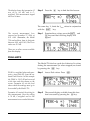
Step 1
Press V to view the greatest value of the
RMS SPL since the beginning of the measurement:
In this example, parameter 61 was
set to 55 dB and C-weighted (parameter 40). In this measurement the
RMS has topped this level 11 times.
Step 2
Press the r key and examine the second
screen available in this series:
6/7/05
Performing a Measurement/Reading the Data
5-5
The display shows that parameter 62
was set to (65 dB) and is Cweighted. This measurement topped
this level 6 times.
Step 3
Press the
r
key to find the third screen:
The same key, V, finds the Lmin values in conjunction
with the U key.
The current measurement Lmin
occurred on November 27, 1996, at
9:21 A.M. (Remember, the Model
720 used military time to designate
between A.M. and P.M.) That Lmin
value was 51.5 dB.
Step 1
Examine these values; press the U and
V keys and the following display will
appear:
There are no other screens available
from this display.
PEAK-UWPK
The Model 720 also has a peak level detector. Its values
during the measurement (or when stopped) are found
by pressing the K key.
PEAK is a weighted value and represents a true Peak SPL from the onboard Peak Detector. In this example
the PEAK is 116.2 dB and occurred
at the time and date shown on the
screen. Parameter 63 sets the level
above which the readings must go to
be recorded by the Model 720.
Step 1
Access Peak values. Press
Parameter 63 controls the setting for
this measurement. Here the setting
is 74 dB, C-weighted and in this
measurement was exceeded 46 times.
Step 2
The second display available from this function is accessed by pressing the r key:
5-6
Model 720 User Manual
K:
6/7/05
Unweighted Peak (UWPK) has two screens available
as well and are accessed with the U and K
keys.
The unweighted peak value is the
unfiltered (no A or C weighting) signal from the Peak Detector.
Step 1
Press U and K and examine these
values for the current reading:
The value for the UWPK is set in
parameter 64 and is 85 dB. This
value was reached 30 times.
Step 2
For the second screen, press the
r
key:
Ln
Ln values are determined by parameters 55-60 and
should be examined next in our current measurement.
Parameters 55-56 in this example
were set to 5 and 10 respectively.
This screen shows their values in
this measurement. These indicate the
sound pressure levels that were
exceeded 5% and 10% of the measurement duration.
Step 1
Access Ln by pressing the B key and a
screen similar to the following will appear:
Parameters 57-58 were set at the
given values shown in the screen
and their readings are apparent.
Step 2
Press the r key to access the second screen:
6/7/05
Performing a Measurement/Reading the Data
5-7
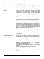
Leq
The average RMS level is 68.2 dB,
slow, average for the 12 minute and
14.9 second measurement period.
The average RMS level, the Leq, is displayed by pressing T.
Dose
DOSE, the noise exposure, may be calculated with
three different sets of parameters:
• Current.
• LDL (Logic Data Log).
• Overall.
Parameters 45-54 are used with the calculation to
arrive at the current dose from the current data and
sets the exchange rate, threshold level, and criteria
level for the current measurement. These can be set
differently from the overall in order to give different
dose readings.
Parameter 51, Full Dose Period (or
Criterion Time) applies to Current
Overall and LDL.
To protect the measurement, the OVERALL Dose settings (parameters 48-50) may not be modified once the
measurement has started without a reset. However,
OVERALL CRITERION may be changed at any time.
If you wish to look at dose with different exchange and
threshold values, LDL may be used by modifying the
LDL settings (parameters 52-54). Note that the run
time for LDL and OVERALL is always the same.
A new measurement may be started at any time without effecting the Overall Dose using the Current Dose
settings by modifying the CURRENT exchange rate
and threshold settings. An automatic reset occurs
5-8
Model 720 User Manual
6/7/05
when CURRENT settings are modified creating a new
CURRENT dose measurement based on data collected
from that time on.
Before we continue with our present measurement,
take a minute to examine the parameter values available, all of which will effect the measurement.
The Current Exchange Rate parameter, item 45, is
accessed by the following steps:
The appropriate value for this
parameter is established by enforcement authorities in various countries. In the USA, OSHA mandates
a 5 dB exchange rate.; 3 dB is common in most other countries.
Step 1
Press O, R, m, 4 and 5, then
e. The choices here are listed below:
[3dB, 4dB, 5dB, 6dB]
Note that these can be changed without a (Reset-all).
The Current Threshold, item 46, has a range from 0 to
255 dB.
The normal Dose setting for threshold is 80 dB which allows the instrument to virtually ignore sound
below that level as it does not contribute significantly to the weight of
the measurement data sought, and
saves memory as well.
Step 2
Press the d key and choose the desired dB
level for the Current Threshold. Larson-Davis
has preset this parameter to 80 dB.
Step 3
If you wish to change this level press m,
enter the desired dB numerically and press
e.
The Current Criterion is the next parameter, item 47,
and has been preset to 90 dB in a range of 0 to 255 dB.
Damage to hearing normally occurs
with lengthy exposure to sound at 90
dB and above. For this reason the
Criterion is generally set at 90 dB.
Step 4
Press the d key, item 47. Press e if
you wish to keep the 90 dB level, or press
m, enter the desired dB numerically and
press e.
The Current Dose is often used as a second Dose measurement. The collected data is available on the printout.
6/7/05
Performing a Measurement/Reading the Data
5-9
The Overall Dose parameters have the same available
settings as the current settings and are accessed in the
same way.
Changes can be made in any display
by pressing m, entering desired values, and pressing e.
Step 5
The overall criterion level set in item
50 and the dose hours set in item 51
determine what is 100% dose.
Full Dose Hours, item 51, has a range of 0 to 99 hours
but is normally set to an 8 hour workday.
OSHA criterion is 90 dB, Threshold
is 80 dB, Exchange Rate is 5 dB, and
the Full Dose hours (Criterion Time)
is 8 dB.
Parameters 52-54 are a second set used to calculate
overall dose from the overall data. Data already in
memory is recalculated with new parameters using
LDL (log Data Logic).
This step will not work while in the
SETUP mode.
This step will not work while in the
SETUP mode either.
5-10
Step 6
To access items 48-50, Overall Exchange Rate,
Overall Threshold, Overall Criterion, press the
d key.
To access Full Dose Hours press the
key.
d
Step 7
To look at DOSE, press
Step 8
To look at Projected Dose, press r to the
PROJ-b screen.
Step 9
If you wish to alter the LDL Exchange,
Threshold or Criterion settings, press m,
enter the desired values, and press e.
E.
Step 10 To look at LDL, press U
and
E.
Dose readings are usually read and have more meaning after the measurement is completed. Return to the
recent measurement and examine the values recorded
there:
Model 720 User Manual
6/7/05
Step 1
The measurement ran for nearly four
hours and the dose was 0.28%.
Press the E key where two screens are
available. Press the r key to access the
second screen:
The Projected Dose extrapolates the
eight hour dose from dose A which is
the current measured dose.
LDL readings are displayed on four screens. View
these screens using the following steps:
Notice in the reading the LDL
Threshold is set at 80 (parameter 49)
The Overall Exchange Rate is set at
3 dB (parameter 48). The overall criterion has been set at 90 (parameter
50). Any of these 3 parameters can
be modified and a new dose, projected dose, Leq, and SEL will be
computed
Step 1
Press the
Step 2
Press the r key to see the fourth screen
for Projected Dose.
U
and
E
keys:
The Overall Criterion has been set at
90 (parameter 50).
-d
6/7/05
Performing a Measurement/Reading the Data
27.87%
5-11
BATTERY
In Chapter 2 we accessed the Battery information to
check the amount or voltage remaining in our battery.
This function has additional screens available. The first
two indicate the amount of voltage remaining and the
second shows the information related to the last revision.
The Revision number and date are
shown.
Step 1
Access the Battery display by pressing U
and B Press the r key to access the
second screen:
Eight additional screens are available from this function. Warning or
Error messages encountered during
normal operation will be displayed
here in the order they happen. They
are accessed by either the l and
r keys, or the u and d keys
which will scroll only the warning
messages.
Step 2
To access the Battery “c” screen press the r
key. To view warning or error messages press
the d key:
MEMORY
Memory will be addressed in Chapter 9, but it would
be well to examine the M key functions here. Standard memory size is 64 Kilobytes. Three screens are
available from this function.
5-12
Model 720 User Manual
6/7/05
Step 1
Press U and M. A screen similar to
the following will appear:
Total Exceedances were 27,total
Intervals were 3, and 1 Daily Histories. Should any of four letters,“OVLD” flash in the place of
the figure in the upper right, this
would indicate there was an Overload during the reading (see chapter
7).
Step 2
Press the
This display indicates there are 8
Histories in memory, 3 Logs and 0
Calibrations. Hs is the number of
time history samples, Lg is the number of RUN/STOP’s made, and CL is
the number of calibration check
records.
Step 3
The third screen gives additional information.
Press the r key to examine this screen:
This screen shows the percentage of
memory left of the total available.
55099 divided by 55197 = 99.82%
r
key to access the next screen:
Stopping the Measurement
Press S to stop the measurement. The stick figure
will resume the resting position. To view any of the
previous measurement data simply press the appropriate key and the information will appear.
6/7/05
Performing a Measurement/Reading the Data
5-13
5-14
Model 720 User Manual
6/7/05
CHAPTER
6
Timed Measurement
The ability to take a measurement at a specific time
and date is one of the unique qualities of the Model
720. This feature allows you to take unattended measurements. Accessed through the TIMER key, this flexible system has modes to permit one or two
measurements a day between two dates, or, a single
block measurement from a start date and time to a stop
date and time.
In this chapter we will discuss:
• Using the Timer for Unattended Readings.
• Using the Time Key Functions.
• Setting the Password Lock to Protect Settings.
Using the Timer for Unattended Readings.
Examine the t capabilities by looking at the parameter
fields:
The Timer parameters, 21-27 begin
with this screen, parameter 21.
Step 1
Turn the Model 720 on, press O followed
by R, U, and t. The following
display will appear:
6/7/05
Timed Measurement
6-1
Block: Run Time 1 on Run Date to
Stop Time 1 on Stop Date.
1/Day: Run Time 1 to Stop Time 1
each day from Run Date to Stop
Date.
2/Day: Run Time 1 to Stop Time1
and Run Time 2 to Stop Time 2 each
day from Run Date to Stop Date.
Step 2
Press m to access the cursor in brackets.
With the brackets flashing use the r to
select one of four possibilities:
[Off, Block, 1/Day, or 2/Day].
Example: Suppose we want to measure a given area
near a large machine in a factory for 5 days, 2 periods
each day.
Step 3
To do this, choose [2/Day] and press e.
Step 4
To continue, press the d
next parameter screen.
to access the
To continue our example, we want to start 26 September at 8:30 A.M. and end at 12:00 noon, begin again at
1:00 P.M. and end at 4:30 P.M. each day for 5 days.
If the date is incorrect, simply press
m and enter the correct data, then
press e.
6-2
Step 5
Press m to change the date and enter 09 26
96. Press e. The new Timer Run Date is
now 26 Sep 1996.
Step 6
To access Timer Stop, press the
ously entered date will appear.
Step 7
To change the date, press m and enter
the 5 day ending date, i.e. October 1, i.e. 01 10
96 e and the following display will
appear.
Model 720 User Manual
d. A Previ-
6/7/05
The five day block is now set. Next we will set
the time periods each day within the block.
Notice that military time is used
(0:01-24:00) to avoid confusion with
A.M. to P.M.
Step 8
Press the d to Run Time 1, and press
m. Our start up time is 8:30 A.M. so press
08 30 and e, and the display should
look like this:
Step 9
Press the d to Stop Time 1. Press m to
enter the numbers 12 00, and then press
e:
Step 10 Press the d to Run Time 2. Press m to
enter 13 00, our afternoon start time. Press
e.
Step 11 Press the d to Stop Time 2. Press m to
enter 16 30 and e.
Step 12 To check your Timer setup, press c.
This will return you to the main screen. Press
Ut and the following screen should
appear:
6/7/05
Timed Measurement
6-3
Step 13 If you press the r key, it will give you the
morning time run. If you press the r
again it will give you the afternoon time run
settings:
The Model 720 can now be turned off by pressing U
O and placed in the test area. Make sure to check the battery (Chapter 2) or connect to external power. Also consider
the safety of the instrument during the test period. Finally,
verify that the current time and date are set correctly in the
internal clock. The following section covers setting the time
and date. The Model 720 will turn itself on and begin measurement at the appropriate time.
Using the Time Key Functions
In Chapter 5 we learned to take a measurement and
examine some of the data gathered during that reading. The TIME key functions as a record of when the
last measurement started. Two screens are available in
this function.
Current time, day, and day of week
are controlled by parameter 6-8.
Step 1
Press U
mation:
and
T to access this infor-
This screen displays the time and
date the current or last measurement
began.
6-4
Model 720 User Manual
6/7/05
The second display shows the current date, day, and time.
Step 2
Press the d key to access the second screen:
Step 3
Press
c
to return to the main screen.
Setting the Password Lock to Protect Settings
The Model 720 SLM can insure that your settings will
not be disturbed by providing a Lock Password
parameter (items 28-34).
Refer to Chapter 4 to review entering
numbers or letters by using the
U key.
Step 1
From the previous field press d, or from
the main screen, press R m 2 8
e. You can also press R, U,
L:
Step 2
Press m and enter your personal combination of numbers or letters from 1-8 characters.
If you choose to use this feature,
enter something you won’t forget i.e.
a name or birth year, and press e.
6/7/05
Timed Measurement
6-5
These setup items (parameters 2834), control whether or not the lock
feature will work for that particular
function. For example, if Yes is
entered for Lock Setup, then the R/S
function can be used when this Lock
function is implemented. Press d to
see other functions that can be
locked. See chapter 8, parameters 2834.
Step 3
To turn on the Lock, press the d, m and
r keys. When [Yes} appears, press e.
Notice that as you enter your code
only (********) appear to protect your
password. Again, make the password
easy to remember should you wish to
use this function.
Step 4
If you should wish to unlock the system for
further input or readings, press U and
L, then m.
Enter your password code and press
e. The Model 720 is now unlocked
and accessible for additional entries.
6-6
Model 720 User Manual
6/7/05
CHAPTER
7
History Functions
The process of measuring and recording units of
sound and retrieving the data for study and understanding is enhanced by additional functional capabilities of the Model 720 Sound Level Meter.
This chapter will cover:
• Setting and Viewing Advanced Functions
- Time History
- Time History Data
- Log and Data
- Interval History
- Interval History Data
- Exceedance
- Setting PassBy functions
• Dealing with OVERLOAD.
Setting and Viewing Advanced functions
The Model 720 has a variety of advanced functions
that allow for gathering and storing great amounts of
data with any given measurement. In this section we
will learn how to access the parameters, choose the
proper settings, and view some of the data collected.
6/7/05
History Functions
7-1
Time History
Time History record includes the RMS integrated level
and, if selected, Peak, Unweighted Peak, or Lmax.
Parameters 80-87 allow you to select the period for the
history and what data are to be saved.
Yes: With this item set to “Yes”, the
time history function is enabled.
Despite Model 720’s large memory,
ensure anticipated requirements do
not exceed available memory.
Normally all data is taken with 0.1
dB resolution (2 bytes/level). To save
memory, this option allows storage
of history in 1.0 dB resolution.
This option allows saving the
weighted peak (Peak), unweighted
Peak (UWPK) or Max RMS level
(Lmax) with each RMS history sample.
Step 1
Turn the Model 720 on and access Time History parameters. Press R H. The following screen, item 80, Time history Enable
appears:
Step 2
To enter [Yes] press m
e.
Step 3
Press the
r to [Yes] and
to item 81, History Resolution:
d
(1.0 dB, 0.1 dB).
Step 4
To change this setting press m
e.
Step 5
To access item 82, Hist Save Peak press
r
d:
[No, Peak, UWPK, Lmax]
Step 6
Step 7
You may press m and make your selection with r and then press e.
Press
thed
to item 83, Hist Period:
(0-255 units)
7-2
Model 720 User Manual
6/7/05
These options select the history
period length as determined by the
value set in parameter #83 times the
units set in parameter #84. For
example, selecting a period of 180
and a unit of 10 seconds would give
1800 seconds or 30 minutes for each
Leq history period. A period of 2 and
a unit of 1/32 second would result in
a history stored every 1/16 second.
Setting Item #83 to 0 is equivalent to
setting it to 256.
Step 8
Use the m and r
you want for this field.
This is for editing purposes only. All
history is stored regardless of this
base level. However, only data above
the base level are displayed.
Step 9
Press the d to item 85, Hist Base. The setting range is: (0-255 dB).
Step 10 To enter a value, press
e.
to select the value
m, the value,
This parameter controls the stored
data which the preceding base level
operates. For example, if this was set
to Peak and the base level set to 100
dB, only peaks 100 dB and above
would be displayed.
Step 11 Press the
The Model 720 provides an amplitude distribution that can be read on
the display. If the resolution is not
satisfactory, a different one may be
selected and the amplitude distribution re-displayed or printed. This is
possible because all data is stored to
the nearest 1/8 dB.
Step 13 Press the d to item 87, Histogram Resolution for these options: [1/8, 1/2, 1.0, 2.0, 5.0, 10]
6/7/05
d
to item 86, Hist Base Mode:
[Off, RMS, Peak].
Step 12 To change the field press m,
e.
r, and
Step 14 Select the value you want. Press m, r
to the proper setting, and then press e.
History Functions
7-3
Time History Data
The Time History is used to view the
data that was acquired with the settings discussed in the previous section. In this example, you will view
the Leq and Peak data that was gathered during the history period.
In Chapter 5 we learned how to take a measurement.
To examine the History of that measurement take the
following steps:
This display contains History information about the measurement. It
was started by a key stroke.
Step 1
To access Time History, press H, and a
screen similar to the following will appear:
Press the d key to view other readings.
Step 2
Press the d key to see the beginning of
dozens of readings:
Log
The Log key is a Run/Stop log. It indicates how many
times the measurement was started and stopped., and
at what time.
Once the measurement is in progress, information can
be examined as follows:
7-4
Model 720 User Manual
6/7/05
This screen gives you information
about the most current readings.
This measurement was started by a
key stroke. The Log screen shows the
cause and action taking place. In this
example “Key” means that a key
such as S caused the action “Run”.
The following actions: Run/Stop,
Pause, Cont., Reset, Mark can be
produced by one of the following
causes: Key, I⁄O, TIMER, CAL,
INTV, BATT, or HALT. Note that
most of the causes are triggered by
software.
The Log information indicates that
the measurement was stopped by
keystroke. If a low battery had been
the reason for the measurement stopping, “BATT” would have appeared.
To retain data already gathered, the
Model 720 will terminate the measurement when battery power
becomes low.
Step 1
Press U and H and several screens
become available:
Step 2
Press the
Step 3
Go back to LOG-a by pressing the r key.
Scroll through the record logs by pressing
d:
Step 4
The u and d keys may be used to look
at additional records. Press the r to look
at associated dates and times.
r key for the next screen:
Interval History
The Interval History parameters allow you to select and
define the Interval size and determine what data are to
be saved.
Each Interval gives you Leq, SEL, Min, Max, Peak,
UWPK, Exceedance count, and, if you turn this feature
on, Ln’s. Listed below is each parameter and a brief
explanation of its function.
6/7/05
History Functions
7-5
To access the Interval History parameters
press OR M. You may also use
numeric values, i.e. OR m 7 2
e. The choices are:
With this item set to (Yes), the Interval Time History is enabled. Note:
Be sure that total memory requirements do not exceed available memory.
Step 1
This parameter is the exchange rate
used for each interval. Set this to 3
dB for community noise and 5 dB for
OSHA studies.
Step 2
This sets the TWA threshold for the
interval time history. For hearing
conservation purposes, 80 dB is recommended. For most community
noise purposes, set this parameter to
0 or slightly above the noise floor.
Step 3
Press the d to item 74, Intv Threshold. You
may find 80 dB preset but you may enter
another value: (0-255).
This sets the period for the interval
history (a 1 second interval may be
selected by entering 00:00).
Step 4
Press the d to item 75, Intv Period. Press
m and the numeric values for the interval
period desired, and then press e:
hh:mm.
The Model 720 allows synchronizing
the interval report with the Daily
History Report. If (Yes) is entered,
the Interval Report will be started
(or restarted if already running) at
the start of each hour. For this to
work properly the Interval Time
should be one hour or some multiples
of hours. The benefit of synchronizing the hourly levels and the interval
reports is that all the statistics Lmax,
Ln, etc.) are available for the hourly
noise levels that make up the daily
report.
Step 5
Press the d to Intv Time Sync, item 76, for
these choices: (Yes, No)
Yes: This option allows the four Lns
for the interval report to be stored.
Step 6
Press the d to item 77, Intv Save Ln’s. The
Choices are: [Yes, No]
7-6
(Yes, No).
Press the d to access the next parameter,
73, Intv Exchange Rate for these choices:
(3dB, 4dB, 5dB, 6dB).
Model 720 User Manual
6/7/05
Step 7
Press the d to item 79, Intv Auto Stop. The
choices are: [Yes, No]
Eight screens are available from the
INTV mode. The screen at the left
gives the Time and Date of a given
Interval. Duration, Leq, Lmin and
Lmax, Peak and UWPK, and the level
setting measurements.
Step 8
To view Interval Histories after a measurement has been taken, press M. A screen
similar to the one below will appear:
INTV-a gives time, interval number
and date
Step 9
Examine the data available in each INTV.
Press r and scroll to each. The l will
also work. Note the scroll is a loop.
Yes: This option will cause the
Model 720 to automatically stop at
the end of each interval, allowing the
precise timing of a series of manual
measurements. To start a new measurement, the
S key must be
pushed.
No: This mode must be off for all
automated measurements. It is recommended that INTV Time Sync be
set to “No” to get the full desired
period.
NTV-b gives duration and interval
number
Step 10 Press the d or u keys to view the next
or previous Interval, respectively.
INTV-c gives SEL and Leq.
INTV-d gives min and max level
and the number of times level went
over RMS exceedance 1.
INTV-e gives peak and unweighted
peak levels.
INTV- f-g gives statistical information. “h” is not used in the 720.
6/7/05
History Functions
7-7
Exceedance
Exceedance is defined as an acoustic event characterized by the sound level going above or exceeding a
predetermined level. An exceedance event requires
the following to occur:
• The SPL must be above the RMS EXCD LVL 1
(parameter 61), or
• the weighted peak level must be above the PEAK
EXCD LEVEL (parameter 63), or
• the unweighted peak level must be above the
UWPK EXCD LEVEL (parameter 64), and
• must be true for longer than the minimum duration (parameter 68).
Exceedance Level parameters are used to define the
noise threshold levels to be used when counting the
number of Exceedance during a measurement. The
number of times one of the four levels were exceeded
will be given in the data report.
To find the Exceedance parameters, items 61-65, turn
the Model 720 on and press the R V. Notice the
available settings, 0 to 255 dB for items 61-64:
• 61 - RMS Excd Lvl 1 - First RMS detector exceedance level.
• 62 - RMS Excd Lvl 2 - Set above Level 1.
• 63 - Peak Excd Level - Weighted peak exceedance
level.
• 64 - Uwpk Excd Level - Unweighted peak exceedance level.
7-8
Model 720 User Manual
6/7/05
After exceedance, level must drop
this amount below the exceedance
threshold before a new exceedance is
logged. This prevents multiple
exceedance for a single event if level
fluctuates about the threshold.
• 65 - Excd Hysteresis - (0-9)
An exceedance count, on the other hand, is obtained
whenever the level goes above RMS EXCD LVL 1,
RMS EXCD LVL 2, PEAK EXCD LVEL, and UWPK
EXCD LEVEL are indicated on the printout respectively. This count has nothing to do with duration but
only indicates the number of times the level went
above the various exceedance levels.
The Exceedance History parameters, items 66-68,
allow you to select and define what data are to be
saved in memory during an exceedance.
Each exceedance indicates the time it started, durations, symmetry, Leq, SEL, Lmax, Peak, and Time History (if desired).
Step 1
Press R and L to access item 66
from the previous field, or press R,
m, 66, and e.
Here is a brief explanation of each parameter:
[Yes} would insure the exceedance
report will be stored in memory
when exceedance conditions 61-65
are met.
• 66 - Excd Enable - [Yes, No]
Used to calculate exceedance integrated level and normally set at 3 dB
(Leq). 4 dB gives L_DOD, 5 dB gives
LOSHA, 6 dB gives L_Avg.
• 67 - Excd Exchange - [3dB, 4dB, 5dB, 6dB]
This parameter sets the minimum
duration in seconds of exceedance
records.
• 68 - Ex Min Duration - (0-255)
6/7/05
Use the d key to scroll through the fields. Use the
m, r and e keys to make any changes
desired within each field.
History Functions
7-9
Tmax
____________
Start of
Exceedance
(Tstart)
Lmax
End of
Exceedance
Hysteresis
___________Threshold______________________
________
______Duration____________
Figure 0-1 Exceedance diagram
The diagram above is an example of an exceedance
with markings of explanation.
It should be noted here that additional parameter settings have been added out of numerical sequence to
satisfy additional needs found in the field. These will
be treated now:
Must be in [Level]. [Passby] treated
later.
• 162 - Excd Trigger: [Level, PassBy]
Occurrence Time = Tstart if set to [Start].
Occurrence Time = Tmax if set to [Max].
T max – T start
Symmetry = 100 × ----------------------------Duration
Lmax must be > RMS Level 1.
Only events that are longer than the minimum duration set and having Lmax greater than the RMS Exceedance Level 1, parameter 61, will be recorded. It is also
important to set the Excd Time History Period to 0.5 or
1 second by entering a 16 or 32 for parameter 70, since
the exceedance time history buffer is used to create this
7-10
Model 720 User Manual
6/7/05
function. The max duration of a passby event is 128
samples which is 64 or 128 seconds depending on
whether 16 or 30 is used in parameter 70.
To examine Exceedance data collected follow these
steps:
Five screens are available. Time and
Date and the Exceedance number,
(as seen in the screen to the left),
Duration, Leq comparisons, Lmax,
Symmetry, Peak and UWPK.
Step 1
Press L. The following screen appears
with some variation:
Step 2
Press the r key to access the five screens
available in the EXCD mode, including Duration, Leq, Lmax, Pk, UWPK.
Step 3
To examine the properties of each exceedance
record use the d key for each of the five
screens.
Setting PassBy Functions
The PassBy Function is a special exceedance event
detector that measures the Lmax, Leq, and SEL of the
highest event to raise and lower Š 10 dB in SPL. It is
used to capture single events such as a vehicle or craft
passby, or other event noises such as blasts or gas getting noise. In addition to the levels measured, the date
and time of the Lmax and the duration of the event are
recorded.The maximum duration of passby event may
be 1 or 2 minutes depending on the shape of the event.
Maximum passby duration will be reduced if exceedance is reduced.
When the Exceedance History and
Passby, parameter 66 and 162, is
enabled, a Passby record will be created whenever a delta 10dB event is
detected (See Figure 7-2).
6/7/05
Step 1
To enable the Passby function, turn on the
Model 720 and then press R, m, 162,
and e. The screen will show either of
two options: [Level, PassBy].
History Functions
7-11
The occurrence time or Maximum
Level must be equal to or greater
than the RMS EXCD LVL 1
(parameter 61).
Step 2
Press m and then press r
[PassBy] and then press e.
to
Passby’s Max
Start of
Exceedance
Occurrence
Time
10dB
Duration
Figure 0-2 Passby Diagram
After taking a reading with [Passby] enabled, you may
wish to examine the Passby events. You may also look
at this while the instrument is running. To do this follow this step:
If “PSBY” appears in the screen it
means you are in the Max PassBy
data screen. Hit U l to get into the
Exceedance PassBy screen.
Step 1
Press L (Exceedance, which is now
Passby), and using the u or d keys,
scroll through the events. Use the l or r
keys to look at information about this event.
Five screens are available here by
using the r key, giving time and date
of the occurrence, duration, and Leq
comparisons.
a. EXCD-a: Time, PassBy record, and date.
b. EXCD-b: Duration and record number of PassBy
event.
c. EXCD-c: SEL and Leq of PassBy event.
7-12
Model 720 User Manual
6/7/05
Symmetry when used in PassBy
mode is an indication of where
Occurrence Time (or Max Level)
occurs in the event. To clarify, 25%
symmetry would indicate Max Level
happened 1/4 of the way into the
event in linear time. 50% would
suggest that the Occurrence Time
happened half way into the event,
and so forth.
d. EXCD-d: Max RMS level and Symmetry of PassBy
record.
The Single Highest Passby event is
accessed by pressing U and l while in
the EXCD Mode.
Step 2
e. EXCD-e: Peak PassBy level and UWPK of PassBy
record.
To examine the Maximum PassBy of all those
collected, press U and the l key.
Use the l and r keys to access the
following data windows:
PSBY-a: Time and Date of maximum PassBy.
PSBY-b: Duration of maximum PassBy.
PSBY-c: Leq and SEL of maximum PassBy.
PSBY-d: Leq and Max RMS level.
Step 3
To return to the Exceedance PassBy data
screens, press U l.
Overload
It should be noted that during any measurement an
OVERLOAD may occur. Such an occurrence happens
when input exceeds all reasonable parameters set by
the Model 720 (such as dropping or jarring the instrument). Should an OVERLOAD occur during a measurement, the data accumulated during the occurrence
will not be accurate.
The Model 720 registers an OVERLOAD in the upper
right corner of the display where the running figure
appears. The figure takes one step each second. At
intervals, 8 seconds apart, the letters O, V, L, D, will
appear in succession. The measurement should be
6/7/05
History Functions
7-13
retaken. The Interval Report on the printout will indicate which interval had the OVERLOAD.
7-14
Model 720 User Manual
6/7/05
CHAPTER
8
Parameters
As we have seen in previous chapters, the Model 720
owes its versatility in great part to a flexible setup.
More than 90 parameters and options can be selected
to tailor the Model 720 to any measurement. Four preprogrammed setups for standard applications are in
memory. One may use these as blueprints for modifications. It is also possible to store up to 11 other setups
in memory for later recall. Along with downloadable
setups from software, this truly makes the Model 720 a
myriad of instruments in one.
In this chapter we will review the following:
• Parameter access keys, R m e c
• Learn to store and retrieve complete setups from
the various memory registers
• List all parameters with a short explanation.
6/7/05
Parameters
8-1
Parameter Key Access Review
Entering and Exiting the Setup Menu
Master Reset: If for some reason it
appears that a master reset is
required (similar to rebooting a PC),
it may be accomplished (with the
unit off) by holding down the V,
S, and l key, and then pushing the
O key. Warning: This is not like
U S in that this procedure
will destroy all data and setups and
return the 720 to the factory default
configuration. You will have to reenter all your setups.
Some setup items may be changed while the Model
720 is running, but parameters influencing data integrity require a memory Reset ALL.
Step 1
Enter the setup by pressing
lowing will appear:
Step 2
To exit back to the main screen, press
c.
Step 3
R.The fol-
Return to the setup menu. Press
R.
Locating Parameters
When in the setup menu, the arrow keys allow movement from one parameter to another. One may also
use a function key or directly index to the appropriate
parameters.
All items in the list of parameters
can be accessed by using the u
and d.
Step 1
From the Setup menu press d to move down
the list of parameters one at a time.
Step 2
When the arrow keys are used in conjunction with the Shift key, U the Model
720 will take you to the top or bottom of the
parameters list.
Press Ud to move to the bottom of
the parameter list.
8-2
Model 720 User Manual
6/7/05
The Model 720 moves you to the
RMS detector parameters.
Step 3
Press the
You are now at the beginning of the
Exceedance parameters, item
61.
Step 4
Press the U
Press e.
C
key.
m keys and then 6 1.
NOTE: Numbers are entered at the current cursor position. Enter
leading zeros if necessary.
Changing Parameters — Enter, Modify
This one has rounded brackets that
mean this is an “entry parameter”.
Type the number or character
desired (see Chapter 4). If there is an
angle bracket “>” then the entry
field is too big to fit the screen and
will scroll with the r key.
Parameters may consist of numeri33cal values, character fields or selected choices. Numerical or character
fields are shown between parentheses:
Another parameter type is the template entry parameter. These prompt for specific data entry. For example:
For both types, follow these simple steps:
For complete coverage of numerical
and alpha entry see chapter 4.
Step 1
Press
Step 2
Enter a value from the numerical keypad. Use
the U key for alphabetical input.
Step 3
Step 4
6/7/05
m.
Confirm any change with e.
Cancel any change by pressing
before e.
Parameters
c
8-3
Parameters whose value is selected from a few possible choices are displayed with the current setting
inside square brackets:
To make a selection:
Step 1
Press m and then the l and r
keys.
Step 2
Confirm change with
Step 3
Cancel change by pressing
e.
e.
c
before
Error Messages:
Entry errors will be noted by a warning message. For
example:
Verify the correct entry format.
Learning to Store and Retrieve Setup Memory
The current setup parameters can be stored internally
in two ways for later recall:
• In two RAM (random access memory) registers
• In one EEPROM register (electronically erasable
programmable read-only memory)
8-4
Model 720 User Manual
6/7/05
Setups stored in RAM occupy the same memory as the
data (64 KB). They may be lost if battery power is
removed for more than a few minutes. One set of
parameters at a time can be stored in the EEPROM.
Parameters in the EEPROM register are secure even if
the batteries are disconnected for long periods of time,
since the EEPROM does not require bias voltage to
maintain its state. A minimum of 5,000 STORE operations are possible with the EEPROM.
Storing a Setup
Remember, to reset memory press U
S e.
The Model 820 must be stopped and memory reset to
store to the EEPROM.
The EEPROM (.) register is the
default. In this instance, the title of
the measurement is “TECH
WRITER”.
Step 1
Press U
Step 2
The u d keys will scroll through the
two RAM registers. For example, press d
twice:
s
The RAM register “1” is empty.
Step 3
6/7/05
To store the current setup to the displayed
RAM 1, register, press e:
Parameters
8-5
Recalling a Setup
Memory must be reset before a recall of setup parameters can be accomplished.
RAM registers 0 and 1 and
EEPROM register will recall previously stored calibration data.
STORE saves the CAL data so that
the calibration for may be stored and
recalled as desired.
Step 1
In the stop mode, press U S e
to reset memory. Then press U R.
Step 2
The EEPROM (.) is again the default. Use r
and d to scroll through the two RAM registers
or u to recall the programmed ROM setups.
Note that the first ROM is the default.
Model 720 Setup Parameters
Setup parameters of the Model 720 are listed below.
Modifying some setup parameters, such as going from
a FAST to a SLOW meter response, may not be
allowed unless the data is reset. This prevents corruption of the overall noise data.
Parameters are listed below in logical groups, with
their number and direct index key (if available). Valid
entry formats are listed, (0), for numerical, [0], for
selection. Some reserved parameters, or selections are
not available. Many of these are active in the Model
870, the Model 720’s big brother.
8-6
Model 720 User Manual
6/7/05
System (1-20) R U S
The following parameters define measurement names,
set clock and determine interface parameters.
No.
Prompt
Entry
Comment
1
Reset ALL Data?
[No Yes]
This parameter allows a U
S without leaving SETUP.
Note: If this parameter is set to
Yes, a RESET will occur, and the
parameter will automatically
revert to No.
2-4
Name
(up to 30 characters)
Place any message you desire in
these 3 lines. (The 3 lines of name
are savable only in EEPROM.)
5
Title
(up to 30 characters)
Used to describe a measurement
or setup
6
Current Time
(hh:mm:ss)
also accessed w/
7
Current Date
(mm/dd/yy)
The 720 is Year 2000 Compliant.
Leap years are considered. For
years less than the year manufactured, the 21st century is assumed
(2000-2092), otherwise the 20th
century is used (1993-1999)
8
Day of Week
[Sun-Sat]
9
Baud Rate
[300-19200]
Baud rate of the serial interface.
Serial printer or computer rate
should be the same.
10
RS-232 Address
(0-127)
Enables addressed communication mode for a network of L•D
SLMs. Each must have a unique
address. Normally only one
Model 720 is used, thus the
address should be set to 0 to disable.
6/7/05
Parameters
U
T
8-7
11
RS-232 Handshaking
[None, Hdwr, XOFF,
Both]
RS-232 handshaking protocol. 720
- SW1 uses [None].
12
COM Ports Handshaking Register
[None, Hdwr, XOFF,
Both]
Serial handshaking protocol.
Model 720 -SW1 uses [None].
Note: To conserve power, the Model
720 turns off the serial port after 255
sec. of non-use. To keep unit on and
connected, an external power supply
must be used.
14
Output 1 Logic
Off
RMS (R)
PEAK (P)
R+P
INTV (I)
True takes it to 5 volts.When set to
Off, DTR is DTR
R+I
P+I
R+P+I
A:D (A)
R+A
P+A
R+P+A
I+A
R+I+A
P+I+A
R+P+I+A
R/S
15
8-8
Output 1 Timer
(enter time)
Model 720 User Manual
Indication that Interval started
and will stay on time set in
parameter 15.
Logic control including “A” are
not applicable to the 720.
Run/Stop
There are 2 modes to the Logic
Output Time now: If the time is
set to 5 sec or less it is assumed to
be a minimum time and the output will be asserted for a minimum of the time selected. If the
time is programmed to be greater
than 5 sec then the time is considered to be the maximum duration
that the pulse should last and the
output will be asserted for a minimum of 5 sec and a maximum of
the time programmed.
6/7/05
20
Power Save
[Auto Off, Manual
Off, Audio Off]
Auto Off: If in the Stop mode and
if no keys are pressed or commands given for 12 min, the
Model 720 will turn off automatically.
Manual Off: The Model 720 will
not turn off until the O key is
pressed, a computer “Off” command is given, or the batteries
become low.
Audio Off: Not available on the
Model 720.
Timer (21-27) U T
These parameters are used when Start and Stop of
measurements are to be controlled by the clock.
No.
Prompt
Entry
Comment
21
Timer Mode
[Off, Block, 1/day,
2/day
Block: Run Time 1 on Run Date
to Stop Time 1 on Stop Date
1/day: Run Time 1 to Stop Time
1 each day from Run Date to
Stop Date
2/day: Run Time 1 to Stop Time
1 and Run Time 2 to Stop Time 2
each day from Run date to Stop
Date
22
Timer Run Date
(dd/mm/yy)
See Timer Mode comment
23
Timer Stop Date
(dd/mm/yy)
See Timer Mode comment
24
Timer Run Time 1
(hh:mm:ss)
See Timer Mode comment
25
Timer Stop Time 1
(hh:mm:ss)
See Timer Mode comment
26
Timer Run Time 2
(hh:mm:ss)
See Timer Mode comment
27
Timer Stop Time 2
(hh:mm:ss)
See Timer Mode comment
6/7/05
Parameters
8-9
Lock (28-34) U L
These parameters limit access of certain functions to
those with the correct password.
For complete instruction on setting
the Lock parameters, see chapter 6.
Step 1
Step 2
After setting password and lock options, exit
the setup and press UL to lock.
To unlock, press UL, then
and enter the password.
m,
No.
Prompt
Entry
Comment
28
Lock Password
(8 characters)
Enter your password
29
Lock R/S Key
[No, Yes]
Lock mode change
30
Lock Setup
[No, Yes]
Lock changes to setup
31
Lock Function
[No, Yes]
Lock changes to displayed function
32
Lock Reset
[No, RES-ALL,
Cur+All]
Lock memory reset
33
Lock ON Key
[No, Yes]
34
Lock I/O
[No, Yes]
8-10
Model 720 User Manual
6/7/05
Calibration (35-36) U C
No.
Prompt
Entry
Comment
35
CAL Level
(114.00)
(0-255 dB)
Enter the sound pressure level of
your calibrator
36
Calibrator S/N
(to 8 char.)
Calibrator serial no. will be printed
Sound Level Meter (39-50) C
These parameters define the sound level meter characteristics. Most changes will require a US
if
memory holds previous data.
No.
Prompt
Entry
Comment
39
Detector
[Slow, Fast, Impl]
Slow: exponential avg: 1 second
constant.
Fast: exponential avg: 1/8 second
constant.
Impl: impulse response.
40
Frequency Weighting
[A,A16,C,C16]
A and C weightings meet Type 2
specifications. Note: A16 and C16
not applicable to the Model 720.
41
AC Out Weighting
[Flat, Wght, F+20,
W+20]
F+20: Flat Level with 20 dB gain.
W+20: Weighted with 20 dB gain.
42
Unweighted Peak
[Flat, C]
44
Reference Level
(0 to 255 dB)
measured level - reference level =
relative level used in some functions
45
Current Exchange
Rate 1
[3dB,4dB,5dB,6dB]
Exchange rate for currant TWA or
Dose readings. For OSHA use 5dB.
46
Current
Threshold 1
(0 to 255 dB)
Levels above threshold are integrated into currant TWA or Dose
readings. For OSHA use 80 dB.
6/7/05
Parameters
8-11
47
Current
Criterion 1
(0 to 255 dB)
100% dose if this level is maintained for full dose period. For
OSHA use 90 dB.
48
Overall
Exchange Rate 2
[3dB,4dB,5dB,6dB]
Exchange rate for overall TWA or
Dose readings.
49
Overall
Threshold 2
(0 to 255 dB)
Levels above threshold are integrated into overall TWA or Dose
readings.
50
Overall
Criterion 2
(0 to 255 dB)
100% dose if this level is maintained for full dose period.
Dose (51-54) E
The noise exposure Dose may be calculated with three
different set of parameters: Current, Overall, and LDL.
See section on occupational noise for additional information. The dose displayed with the E key is the
Overall Dose.
No.
Prompt
Entry
Comment
51
Full Dose Hours
(0 - 99)
This is normally set to 8 for an 8
hour workday. It is used with the
criterion level to determine a 100%
projected dose.
52
LDL Exchange
[3dB,4dB,5dB,6dB]
Use LDL function to reevaluate
stored data with new dose parameters.
53
LDL Threshold
(0-255 dB)
54
LDL Criterion
(0-255 dB)
8-12
Model 720 User Manual
6/7/05
LN Statistical Levels (55-58) B
Lnn is the RMS noise level which was exceeded nn% of
the time. The Ln’s are computed from the overall level
distribution histogram or each interval’s level histogram (see item 77). The measured and displayed Lnn
may be changed during the measurement. The four nn
are automatically listed in increasing order.
No.
Prompt
Entry
Comment
55
Lnn 1 Percent
(0 to 99)
56
Lnn 2 Percent
(0 to 99)
57
Lnn 3 Percent
(0 to 99)
58
Lnn 4 Percent
(0 to 99)
Exceedance Levels (61-65) V
These parameters define noise threshold levels to be
used when counting the number of exceedances during a measurement (viewed in MAX-b and c displays
for rms, PEAK-b, UWPK-b for peak exceedance), and
triggering the exceedance history (see parameter 66).
No.
Prompt
Entry
Comment
61
RMS Excd Lvl 1
(0 - 255 dB)
First rms detector exceedance
level.
62
RMS Excd Lvl 2
(0 - 255 dB)
Set above Level 1.
63
Peak Excd Level
(0 - 255 dB)
Weighted peak exceedance level.
64
Uwpk Excd Level
(0 - 255 dB)
Unweighted peak exceedance
level.
6/7/05
Parameters
8-13
65
Excd Hysteresis
(0 - 9)
This sets the amount, once an
exceedance occurs, that the level
must drop below the exceedance
level before the Exceedance event
ends and a new exceedance can
occur. Normally set this level to 2
or 3 dB. This prevents multiple
exceedances for a single event if
the level flickers around the
threshold.
Exceedance History (66-68, 162)
These parameters select and define what data are to be
saved in memory during an exceedance.
No.
Prompt
Entry
Comment
66
Excd Enable
[No, Yes]
Yes: Exceedance report will be
stored in memory when exceedance conditions above are met.
67
Excd Exchange
[3dB,4dB,5dB,6dB]
Used to calculate exceedance integrated level. Normally this is set
to 3dB (Leq). 4dB gives L_DOD,
5dB gives LOSHA, 6dB gives
L_Avg.
68
Ex Min Duration
(0-255)
Exceedance must last at least this
many seconds to be logged.
162
Excd Trigger
[Level, Bypass]
Bypass: Enables a variable threshold.
8-14
Model 720 User Manual
6/7/05
Interval History (72-79) M
No
.
Prompt
Entry
Comment
72
Intv Enable
[No, Yes]
Interval report will be stored in
memory if Yes is entered.
73
Intv Exchange
[3dB, 4dB, 5dB, 6dB]
Used to calculate interval integrated level. Normally this is set to
3 dB (Leq). 4 dB gives LDOD, 5 dB:
LOSHA, 6 dB: LAvg.
74
Intv Threshold
(0 to 255 dB)
Levels above threshold are integrated during each interval, normally 0 dB for Leq. For noise
hygiene interval TWA, set to dose
threshold.
75
Intv Period
(hh:mm)
This sets the period for the interval
history from 1 minute up to 99:59.
A 1 second interval may also be
selected by entering 00:00.
76
Intv Time Sync
[No, Yes]
Synchronizes start of interval with
clock and daily history report. If
Yes is entered, the interval report
will be started (or restarted if
already running) at the start of
each hour or minute depending on
Intv duration.
77
Intv Save Ln’s
[No, Yes]
Selects whether interval Ln’s are
stored. The Ln’s stored are those in
effect (items 55-60) at end of interval.
79
Intv Auto Stop
[No, Yes]
If yes, automatically stops instrument at the end of each interval for
precise timing of series of manual
measurements. Use R/S key to
restart.
6/7/05
Parameters
8-15
Time History (80-87) H
This third type of history is the most conventional. The
rms integrated level and, if selected, a maximum reading are stored in memory at the end of each time history period.
No
.
Prompt
Entry
Comment
80
HIST Enable
[No, Yes]
Time history report will be stored
if Yes is entered. Despite the
Model 720’s large memory, ensure
anticipated requirements do not
exceed available memory.
81
Hist Resolution
[0.1dB, 1.0dB]
Normally, all data is taken with
0.1 dB resolution (2bytes/level).
Allows storage of history with 1
dB resolution to conserve memory(1byte/level).
82
Hist Save Peak
[No, Peak, UWPk,
Lmax]
This option allows saving the history period’s highest weighted
(Peak), unweighted Peak (UWPk)
or RMS level (Lmax) with each
RMS history sample.
83
Hist Period
(1-255 units)
Multiplier of units of time below
sets rate at which history samples
are stored. Ex: 1 x 60.0s for minute
by minute history, 16 x 1/32s for
0.5 second history.
85
Hist Base
(0-255 dB)
This is for editing purposes only.
All history is stored regardless of
this base level. However, only
noise data above the base level are
displayed on the screen.
86
Hist Base Mode
[Off, RMS, Peak]
Type of noise data used by the
base mode
8-16
Model 720 User Manual
6/7/05
87
Histogram Resolution
[1/8, 1/2, 1.0, 2.0, 5.0,
10]
Selects the interval in dB of the
overall time level amplitude distribution.
Print Options (89-112) s
These parameters allow for tailored reports of the
Model 720 data during or after the measurement. They
can be accessed from outside the SETUP by pressing s,
then 7 for printer type and options. Refer to section on
printouts for samples of information found on each
printout.
No.
Prompt
Entry
Comment
89
Prn Data Report
[No, Yes]
Prints quick data report.
90
R/S and Cal Log
[No, Yes]
Prints Run/Stop and calibration
log report.
91
Setup Report
[No, Yes]
Prints list of current setup parameters.
92
RMS Histogram
[No, Yes]
Prints histogram of overall rms
levels.
93
Lowest Level
(0 - 255)
RMS Histogram lowest printed
level
94
Highest Level
(0 - 255)
RMS Histogram highest printed
level
95
Histogram Resl.
[1/8, 1/2,
1.0,2.0,5.0,10]
Spacing in dB between histogram
entries
96
Peak Histogram
[No, Yes]
Prints histogram of overall peak
levels.
97
Lowest Level
(0 - 255)
Peak Histogram lowest printed
level
98
Highest Level
(0 - 255)
Peak Histogram highest printed
level
6/7/05
Parameters
8-17
99
Histogram Resl.
[1.0,2.0,5.0,10]
Spacing in dB between histogram
entries
100
UwPk Histogram
[No, Yes]
Prints histogram of overall
unweighted peak levels.
101
Lowest Level
(0 - 255)
UWPk Histogram lowest printed
level
102
Highest Level
(0 - 255)
UWPk Histogram highest printed
level
103
Histogram Resl.
[1.0,2.0,5.0,10]
Spacing in dB between histogram
entries
104
EXCD Report
[No, Short, Long]
Prints exceedance report.
105
Lowest Rec. #
(0 - 65535)
Starting exceedance record number of printout
106
Highest Rec. #
(0 - 65535)
Ending exceedance record number of printout
107
INTV Report
[No, Short, Long]
Prints interval report
108
Lowest Rec. #
(0 - 65535)
Starting interval record number of
printout
109
Highest Rec. #
(0 - 65535)
Ending interval record number of
printout
110
HIST Report
[No, Yes]
Prints time history report
111
Lowest Rec. #
(0 ->999999)
Starting history record number of
printout
112
Highest Rec. #
(0 ->999999)
Ending history record number of
printout
8-18
Model 720 User Manual
6/7/05
Additional System Functions (159,162)
No.
Prompt
Entry
Comment
159
Power Mode
[Normal, Ext CO]
Normal: meter uses internal battery unless greater external voltage is also applied.
Ext CO: (external cutoff) when
external power falls below 10.5 V,
meter turns off to prevent battery
damage.
162
EXCD Trigger
[Level, Passby]
Passby: Enables a variable threshold
6/7/05
Parameters
8-19
8-20
Model 720 User Manual
6/7/05
CHAPTER
9
Memory Usage
Each of the Model 720’s History Functions use space
out of a common memory. The amount each record
takes is based on the options selected. In this chapter
we will provide information that will assist you to:
• Determine the amount of storable data considering
the given options.
• Estimate memory usage by giving an example of a
test reading and an associated chart to determine
the memory needed to complete the reading.
Determine Storable Data
The following tables indicate the amount of memory
used for each type of record:
Exceedance Records
Excd History Enable = [Yes] Prm66
Options -- add bytes shown if enabled
Bytes
Basic Exceedance Record
32
Interval Records
Intv History Enable = [Yes] Prm 72
Options -- add bytes shown if enabled
Bytes
Basic Interval Record
34
Intv Save Ln’s = [Yes] Prm 77
+18
6/7/05
Memory Usage
9-1
Time History Records
Time History Enable =
[Yes] Prm 80
Options
Bytes
Hist Resolution Prm 81
Hist Save Peak Prm 82
[1.0dB]
[No]
1
[0.1dB]
[No]
2
[1.0dB]
[Peak, UwPk, Max, Wind]
2
[0.1dB]
[Peak, UwPk, Max, Wind]
4
Other Histories and Memory Usage
Bytes
Run Log History
20 bytes per record
Calibration Log History
17 bytes per record
Ram Setup Register
(Registers 0-9, Bytes used per register stored)
506 bytes per register
Estimating Memory Usage
The easiest way to estimate the memory usage is to
work on a time basis such as one day. Consider the following:
• Estimate how many Exceedances will occur in a
normal day
• Calculate the number of Interval, Time History,
Daily, Run Log and Calibration Check records that
will be performed in a day.
• Based on the options chosen calculate the number
of bytes required for each record type.
• Multiply by the number of records expected per
day,
9-2
Model 720 User Manual
6/7/05
• Sum these values and this is the number of bytes
required per day.
• Divide this value into the amount of available
memory in the Model 720 (see U M) and this is the
number of days the Model 720 can gather data.
As an example, let's assume a job requires monitoring
the noise made by trucks coming and going from a factory near a residential area. From an initial site survey
it is discovered that all trucks are over 65dBA at the
boundary of the road and residential property and that
there seems to be a truck passing the site every 3 minutes. The occupants of the residential area want to
know how many trucks are traveling this road and
why they are disturbed by some more than others. The
Exceedance Function will be used to detect events over
65dBA and there is expected 20 events per hour or 240
per day (20 events/hour time 12 hours/day) assuming
that the plant operations will be reduced during the
night. Statistics based on hourly intervals and a one
minute time history are desired to identify disturbance
pattern. The following completed work sheet shows
the calculations for this example:
Line
Exceedance Memory Estimation
Bytes
4Used
Bytes needed
1
Basic Exceedance Record
32
4
32
2
Save Full Accumulator and Count in
Binary (aux Cntl Reg bit value 16)
prm210
16
4
16
3
TOTAL Bytes / Excd
sum lines
1-2
>>>>>>
48
4
Anticipated Excd / Day
Enter
Number
>>>>>>
240
5
TOTAL Excd Bytes / Day
Multiply
lines 3 &
4
>>>>>>
11520
6/7/05
Memory Usage
9-3
Line
Interval Memory Estimation
Bytes
4Used
Bytes needed
6
Basic Interval Record
34
4
34
7
Intv Save Ln’s = [Yes] Prm 77
18
4
18
8
Intv Save Ln Table
384
9
TOTAL Bytes / Intv
sum lines
6-8
>>>>>>
52
10
Anticipated Intv / Day
Enter
Number
>>>>>>
24
11
TOTAL Excd Bytes / Day
Multiply
lines
9&10
>>>>>>
1248
Line
Time History Memory Calculation
Bytes
Hist Resolution
Hist Save Peak
16
[1.0dB]
[No]
1
17
[0.1dB]
[No]
2
18
[1.0dB]
[Peak|UwPk|Max|Wind]
2
19
[0.1dB]
[Peak|UwPk|Max|Wind]
4
20
TOTAL bytes / Hist Record
Select the appropriate # of
bytes from lines 16-19
2
21
Hist Records / Day
24 hours divided by Hist Period in
hours
Enter Number Calculate
i.e. 24/(60 sec/3600 sec per
hour)= 1440
1440
22
TOTAL Hist Bytes / Day
Multiply lines 23 and 24 copy
-copy to 29
2880
Line
Memory Use per Day Calculation
Bytes
Bytes
23
Exceedance History bytes / day
from line 5
11520
9-4
Model 720 User Manual
0
Bytes
6/7/05
Line
Memory Use per Day Calculation
Bytes
Bytes
24
Interval History bytes / day
from line 11
1248
26
Time History bytes / day
from line 22
2880
27
Run Log bytes / day
n= number of Run Log records / day
2/(nx20) X 20 =
n x 20 bytes/record
40
28
Calibration Log bytes / day
1/(nx17) X 17
n x 17 bytes/record
17
29
Setup RAM Registers bytes used
n=number of registers stored / day
0/(nx506) =
n x 506 bytes/record
0
30
TOTAL bytes used / day
Sum lines 23-29
15,705
31
Model 720’s Memory Size (64000)
See SYSTEM-b
64,000
32
TOTAL Run Time in days
until out of memory
Divide line 31 by 30
4.07
6/7/05
Memory Usage
9-5
9-6
Model 720 User Manual
6/7/05
CHAPTER
10
Printing a Report
The Model 820 allows for tailored reports of data during and after measurements. In this chapter we will
access the printing option parameters for Normal
Printouts and print a report.
Normal Printout Parameters
Before proceeding with printing, baud rate needs to be
determined and entered. Set parameter 9 to proper
baud rate determined by type of printer used. If, after
starting printing, bad information is printed, baud rate
or printer type is probably set incorrectly. To cancel
printing, hit U and S.
Normal printouts can be accessed from outside the
SETUP mode by following these steps:
Step 1
6/7/05
Turn the Model 720 on and press s. The
following display will appear briefly and
then scroll automatically through several
options:
Printing a Report
10-1
Step 2
To tailor your report and select the printer
type and options, press 7 and the following
screen will appear:
There are several options here which include:
[HPJet, HPLzr, ASCII, Epson, IBM]
Items 89-112 allow you to select the
reports which are to be printed and
how the output data are to be configured.
Items 89-112 are copied sequentially
into items 177-200 for printing tailored reports, and may be edited
directly for one printing, and then
they will revert to settings entered in
parameters 89-112.
Step 3
You can change the printer selection by pressing the m key and then r to the
printer you will use, and press e.
Step 4
Press the d key to the next display, item
89 (duplicated here as item 177), the beginning of the parameters that manage printouts:
Step 5
Scroll through these parameters with the d
key and make your selections. Press m
to access the appropriate choice and press
e.
NOTE: For a complete list of Print Options, see Chapter 8.
Printing Reports
Printing reports is easy as connecting your Model 720
to a printer and pressing a key. Using the CBL033
serial printer cable, connect your serial printer to the
Model 820 at its bottom port. Let’s look at the print
options again:
10-2
Model 720 User Manual
6/7/05
You will notice that the scroll is
quite rapid. To slow it down so you
can study the options, use the u or d
keys and the display will remain for
five seconds before returning to
automatic scroll.
Step 1
Turn the Model 720 on and press s. The
display will begin to scroll through the various print options available. Here are some of
the screens:
Step 2
Press the d key until you find the Exceedance History report screen:
Step 3
To generate an Exceedance Report, press the
L key. Assuming your reading has Exceedances, the report will contain all recorded
occurrences during the test period.
A “+” following the key name indicates the option function will be
invoked after selecting that key, otherwise the particular report will be
printed immediately.
This option allows you to access the
printer setup status.
This option will return you to the
Printout Parameters and will start
with the printer type selection. The d
key will access item 89 of the Printout Parameters.
This option allows you to tailor your
own report changing the settings of
parameter items 89-112.
The brackets contain the command
that will produce the Exceedance
Report, i.e. [EXCD].
6/7/05
Printing a Report
10-3
10-4
Model 720 User Manual
6/7/05
CHAPTER
A
Specifications
This Appendix contains the specifications for the
Model 720 in the following order:
• Type
• Reference Direction
• Measurement Ranges
• Reference Level
• Frequency Weighting
• Detector Time Weightings
• Effects of Temperature
• Effects of Humidity
• Limits of Temperature and Humidity
• Microphone Extension Cables
• Positioning of Instrument and Observer for Best
Measurements
• AC and DC Outputs
• Reference Frequency
• Stabilization Time
• Microphone Electrical Impedance
• Functions Measured
• Data Storage
6/7/05
A-1
• Data Communications
• Digital Display
• Digital Display Resolution
• Display Bargraph
• Real-time Clock/Calendar
• Run-time Clock
• Typical Noise Floors
• Standards Met
• Power Supply
• Dimensions/Weight (with Microphone, Preamplifier, and Battery)
Type
The Larson•Davis Model 720 with attached PRM 828
preamp and Model 2541 microphone is a combination
Type 2 precision integrating sound level meter and statistical data logger.
Reference Direction
The reference direction is perpendicular to the plane of
the microphone diaphragm when using a free field
microphone in a free field. The microphone should be
pointed directly at the source.
When using a random incident microphone in a free
field, the microphone should be pointed 80 degrees off
axis of the source of the sound.
When in a random sound field, a random incident
microphone may be pointed in any direction.
A-2
Model 720 User Manual
6/7/05
Measurement Ranges
RMS Detector
Dynamic Range > 110.0 dB
Primary Indicator Range > 105.0 dB
The instrument will have a different Noise Floor,
Lower Limit, and Overload Level, depending on the
sensitivity of the microphone used. Some typical values, for 2 different Larson•Davis microphones, are
listed in the table below.
A Weight
Noise Floor dBSPL
C Weight
Noise Floor dBSPL
Lower Limit
dBSPL
Overload
Level
dBSPL
Max Peak
Level dBSPL
Max Level for
Pulses of
Crest Factor
= 10
dBSPL
30.5
30.0
35.5
142.0
145.0
124.0
The data in the above table was obtained by electrically testing a number of instruments. For all electrical
tests, the microphone was replaced with an equivalent
electrical impedance (Larson•Davis ADP018 microphone adapter).
Other Detectors
• Weighted Peak Detector = 85.0 dB
• Unweighted Peak Detector = 38.0 dB
• AC Output = 85.0 dB
• DC Output = 105.0 dB
Reference Level
The reference level is 114.0 dB SPL.
6/7/05
A -3
Frequency Weightings
The available frequency weightings for the Models 720
are described in the table below.
Detector
A Weight
C Weight
RMS
√
√
Weighted Peak
√
√
Unweighted Peak
Flat Weighting
√
√
√
AC Output
√
√
DC Output
√
√
NOTES:
1. The RMS frequency weighting is selected via parameter #40, “Frequency Weighting”. The Weighted Peak
Detector, and DC Output frequency weighting always
matches the RMS Detector frequency weighting.
2. The Unweighted Peak Detector frequency weighting
is selected via parameter #42 “UWPK Weighting”;
therefore, it can be set independent of the RMS Detector frequency weighting. The Unweighted Peak Detector’s typical FLAT frequency response is shown in the
table below.
3. The AC Output frequency weighting is selected via
parameter #41, “AC Out Weighting”. It can be set to
Flat weighting, or it can be set to match the RMS Detector frequency weighting. The AC output’s FLAT frequency response is shown in the table below.
Unweighted Peak FLAT Frequency Response
Nominal
Frequency Hz
Unweighted Peak
FLAT Weighting dB
Nominal Frequency Hz
Unweighted Peak
FLAT Weighting dB
Nominal
Frequency Hz
A-4
Unweighted Peak
FLAT Weighting dB
10
-3.4
160
0.0
2500
0.0
12.5
-2.5
200
0.0
3150
-0.1
16
-1.7
250
0.0
4000
-0.2
Model 720 User Manual
6/7/05
Unweighted Peak FLAT Frequency Response
20
-1.2
315
0.0
5000
-0.2
25
-0.8
400
0.0
6300
-0.3
31.5
-0.5
500
0.0
8000
-0.4
40
-0.3
630
0.0
10000
-0.5
50
-0.2
800
0.0
12500
-0.8
63
-0.1
1000
0.0
16000
-0.9
80
0.0
1250
0.0
20000
-1.2
100
0.0
1600
0.0
125
0.0
2000
0.0
AC Output FLAT Frequency Response
Nominal
Frequency Hz
AC Output FLAT
Weighting - dB
Nominal
Frequency Hz
AC Output FLAT
Weighting - dB
Nominal
Frequency Hz
AC Output FLAT
Weighting - dB
10
-7.6
160
-0.1
2500
0.0
12.5
-6.2
200
-0.1
3150
0.0
16
-4.7
250
-0.1
4000
0.0
20
-3.5
315
0.0
5000
0.0
25
-2.5
400
0.0
6300
0.0
31.5
-1.7
500
0.0
8000
-0.1
40
-1.2
630
0.0
10000
-0.1
50
-0.9
800
0.0
12500
-0.2
63
-0.6
1000
0.0
16000
-0.3
80
-0.3
1250
0.0
20000
-0.5
100
-0.3
1600
0.0
125
-0.2
2000
0.0
Detector Time Weightings
The available RMS detector time weightings are FAST,
SLOW, and IMPULSE. There are also two available
PEAK detectors (Weighted Peak, Unweighted Peak).
• Weighted Peak Detector Rise Time: 60 µs
• Unweighted Peak Detector Rise Time: 30 µs
6/7/05
A -5
Effects of Temperature
The SPL level varies ð 0.5 dB when the complete
instrument is tested over the -10° C to 50° C temperature range. The reference reading, for this test, is taken
at 20° C and 36% relative humidity (RH); the input signal is at 1000 Hz.
Effects of Humidly
The SPL level varies ð 0.5 dB when the complete
instrument is tested over the 30% to 90% RH range.
This test is performed at 40° C, with an input signal of
1000 Hz.
Limits of Temperature and Humidity
Permanent damage can occur when stored or operated
above 60° C or below -20° C. Condensation of moisture
will make readings inaccurate but will be correct when
moisture has dissipated.
Positioning of Instrument and Observer for Best
Measurements
Measurements can be made with the Model 720 held in
one hand, with the arm extended away from the body;
however, better measurements can be made with the
Model 720 placed on a tripod.
AC and DC Outputs
The output impedance is 600 ¾ for both the AC and
DC outputs of the Model 720. For minimal error use
A-6
Model 720 User Manual
6/7/05
instruments with Š 100 k¾ input impedance when
making AC or DC output readings.
AC Output
• Output Impedance: 600 ¾
• Gain: 0 dB or 20 dB (User Selectable)
• Measurement Range: 88.0 dB
DC Output
• Output Impedance: 600 ¾
• Scale: 20 mV/dB
• Measurement Range: 105.0 dB
• Voltage Range: 0 to 3 volts
• Temperature Coefficient: 936 µV/° C
Reference Frequency
The reference frequency is 1000 Hz.
Stabilization Time
The Model 720 will not proceed to a running condition
until it is allowed to stabilize. At power-on, the stabilization time is approximately 10 seconds. A shorter stabilization time is also invoked when certain settings
(Weighting, Detector, etc.) are changed.
6/7/05
A -7
Microphone Electrical Impedance
The Larson•Davis ADP018 should be substituted for
the 3/8" microphone when performing electrical tests
on the Model 720.
Functions Measured
• Leq, Lmax, Lmin, TWA, SEL
• Dose, Projected Dose, Ln (1% - 99%)
• Sound Exposure in pascal squared hours (SE in
Pa2H)
• Time History, Histograms, Measurement TimeDate-Duration
• Taktmaximal 3 and 5
• Exceedance Events
Data Storage
• 64k byte Memory
Typically, 3 month memory retention with fresh battery.
Memory protected during battery change (2 minutes
minimum).
Data Communications
• Serial interface for computer, printer, and modem
communications
• Data Rate: 19,200 bits per second
A-8
Model 720 User Manual
6/7/05
Digital Display
• 2 line, 32 digit, 7 segment LCD
• Full ASCII character set
• Fully annotated date displays parameter with units
Digital Display Resolution
• dB levels: 0.1 dB
• Dose: 0.01%
• Elapsed Time: 0.1 second
Display Bargraph
• 120 dB range, 1 dB resolution for SPL
Real-time Clock/Calendar
• 24 hour clock: hh:mm:ss
• 1 second resolution
• 100 year calendar: 01JAN1999
• Automatic run/stop timer with two alarms and
four alarm times
• Year 2000 compliant
Run-time Clock
• 0.1 second resolution
• Format: hhhhh:mm:ss.s
6/7/05
A -9
• Maximum > 4 years
Standards Met
• ANSI S1.4-1983 Type 2
• ANSI S1.25-1991 Type 2
• IEC 651 Type 2
• IEC 804 Type 2
• Directive 86/188/EEC
• Directive IEC/TC-29
Power Supply
• Internal: 9 V battery, typically 20 hour operation
(actual run-times vary depending on operating conditions)
• External: 7 to 16 VDC, 30 mA current drain
• Battery-life indication selected from keyboard or
computer program
Dimensions/Weight (with Microphone, Preamplifier and
Battery)
• Width: 3in. (7.5 cm)
• Length: 8 in. (20 cm)
• Length: 6 in. (15 cm) without nose cone
• Depth: 1.0 in. (2.5 cm)
• Weight (with battery): 11 oz. (326 gm)
• Shipping weight: 3 lbs (1.4 kg)
A-10
Model 720 User Manual
6/7/05
CHAPTER
B
Serial Port Interface Remote
Control
The Model 720 is fully controllable remotely via Serial
Port interface. Setup items and operational mode can
be altered. Data can also be dumped to or queried by
the controlling computer.
The Model 720 may be connected to the computer
directly or through a modem that is initialized to be
operate to be operated transparently (Auto-answer, no
echo, and no responce: ATE0X0V0Q1S0=1). A network
of many instruments can be formed, all controlled by
one computer by using the address-ability mode.
This chapter will describe the Serial Port interfacing of
the Model 720 and the various interface commands
with their syntax. These commands are a subset of the
Larson•Davis Model 870 commands.
In this chapter we will cover the following items:
• Model INT002 Interface Cable ............................................2
• Daisy Chain Addressing......................................................2
• Commands.............................................................................3
• Group Read Programming................................................11
• Querying and Setting Parameters ....................................12
• Parameter List .....................................................................16
• History Records ..................................................................22
• History Data Variables.......................................................23
• Print Commands.................................................................27
• Error Messages and Warnings..........................................28
6/7/05
B-1
Model INT002 Interface Cable
The Serial Port communication is made through the 5pin connector at the base of the Model 720. Interface
signals usually need to be converted for proper communication with desktop computers. The Model
INT002 Cable/Level Converter is required for this
purpose. Its electronic circuits provide the correct RS232 signal levels and polarities. When used with the
AC/DC adapter, the INT002 also powers the units
externally, minimizing battery depletion during Serial
Port transfers.
Baud rate, Serial Port address and
handshaking protocol are selected
using parameters 9, 10 and 12.
Unless using addressing, set the
address to (0).
Step 1
With the instrument turned off, insert the
cable connector in the 5-pin port.
Step 2
Connect the cable to the of the computer,
using the supplied 9-25 pin adapter if necessary.
Signal 5-Pin configurations for the INT002 follow:
712, 720, 812,& 820 5-pin Connector
End
Ground Pin1/Shield
TXD
Pin 2/Red
RXD
Pin3/Yellow
Power
Pin4/Blue
DTR
Pin 5/White
DSR
CTS
Computer DB-9
Connector End
Pin5/Shield
Pin 3/Red
Pin 2/Yellow
Pin 4/Blue
Pin 6/White
Pin 8/White
Daisy Chain Addressing
The following instruments are compatible on a common network: Models 712, 720, 812, 820, 870, and
TAC100. Future instruments may
also be compatible with this network.
B-2
A network of instruments may be interconnected to
one computer using the appropriate cabling, such as
the CBL040, and each may be controlled individually.
Each is given a unique address (parameter 10). The
addresses are sent as a single byte ranging in value
from 129 to 255 representing address 1 to 127 respectively (address plus 128).Whenever an address byte is
received only the corresponding instrument is enabled
to receive commands.
Model 720 User Manual
6/7/05
A broadcast command can be sent. By sending an
address of zero, CHR$(128), all units on the chain will
become addressed and accept the commands that follow. Only the device with an address of 1 will respond
to the commands if data transfer is required. This will
allow all units to be started at the same moment, or to
have the same parameter sent to all devices with one
command, i.e. set all clocks to the same time.
WARNING!
These devices cannot be just paralleled together. That
would short outputs together and damage the instruments. Use the designated cables.
Commands
The commands are a series of ASCII characters with an
alpha command and one or two numeric operands followed by a charge return, ASCII 13. The commands
may be spelled out though only the first character is
significant. i.e. READ 123 may be abbreviated to R123.
Every command has a response to acknowledge that it
was received correctly and to provide data requested.
The following tables summarize all of the commands
and are listed in this order: mode control commands
first, parameter commands next, data extraction command and report/data download command last.
[.] Square brackets indicate optional characters or operands.
Syntax
Response
R[ead] variable_number, operand_2]
variable_value
S[et] parameter_number, parameter_value
acknowledge
S[et] parameter_number, option_number
acknowledge
S[et] parameter_number; option_text
acknowledge i.e. “Set 8; [Thu]” will set day of week to
Thursday
Q[uery] parameter_number, option_flags]
parameter_value
6/7/05
B -3
Query Option flags may be added for combined effect.
32-Index Number
8-Tab over response
2-print in braces
1-Print parameter name
K[ey] key_simulation_string
acknowledge
M[ode] mode_number
acknowledge
History Oriented Commands
E[xceedance] variable_number [,relative_rec]
variable_value
E[xceedance] variable_number [,time_hist_num]
variable_value
I[nterval] variable_number [,relative_rec]
variable_value
L[og] variable_number [,relative_rec]
variable_value
C[alibration] variable_number
variable_value
H[istory] variable_number [,relative_rec]
variable_value
T[ables] variable_number [, table]
variable_value
A[dvance] range [,history_number]
acknowledge
B[ackup] range [,history_number]
acknowledge
F[ind] record_number [,history_number]
acknowledge
P[rint] report_number
acknowledge
B-4
Model 720 User Manual
6/7/05
Mode Commands
Format for the Mode Commands is:
Command
Description
M1
Power On, clear error message list and reset display functions to “–a” windows
M2
Power Off
M3
Run
M4
Stop
M5
View
M6
Mark
M7
Reset Current Data (use S1,1 for Reset-All)
M8
Reset Histories Only
M 9,1
High Resolution Levels (to I/O channel only). Increased resolution I/O is possible by using the M9,1 command. All sound levels are then sent with an additional fractional character (nnn.nn) giving 1/100th dB resolution. The Model
720 acquires noise data with 1/32 dB resolution. Greater resolution is
achieved through averaging. HOWEVER, THIS DOES NOT IMPROVE
ACCURACY. Refer to the specifications or device specific performance
results for the accuracy of the system.
M 9,0
Restores 1/10th dB resolution
M 10
Lock 720 (leave 720’s power on)
M 11
Lock 720 and Power Off.To unlock the unit and send the lock combination to the unlock parameter with the S230,cccccccc command where cccccccc is the correct combination entered
before locking.
M 1000
Non-destructive memory test (walking bit)
M 1001
Destructive memory test (pattern test)
M 2222
Store current settings and calibration to EEPROM
6/7/05
B -5
“Read” Variables
Syntax
Variable
Description
Response
R1
_DEVTYPE
Device manf. and model
String
R2
_DT.TM
Current Date and Time
ddd ddmmmyyyy hh:mm:ss
R3
_STAT
Status
RUN/PAUSE/STOP/RESET-C/
RESET-O, LOCKED
A short form of the status command is R3,1 which has
a 5 character response.
• The first is an “s” when stabilizing or a space when
ready.
• The second is the current mode: “S” for Stopped,
“R” for Running, “P” for Paused, “C” for Calibrating, “V” for View mode, “O” for stopped with overall data reset and “C” for stopped with Current
data set reset.
• The third character is the Lock Status and is either
an “L” or a “U”. The fourth character is the Halt
Line Status and is a “1” if high and a “0” if low. The
fifth or last character will be an “a” if an Alarm has
been detected.
R4
_C.SPL
Current SPL
nnn.nn dB
R5
_O.RTIME
OverAll Runtime
hhhhh:mm:ss.s
R6
_O.STIME
OverAll Start Date and Time
ddmmmyy hh:mm:ss
R7
_C.RTIME
Current Runtime
hhhhh:mm:ss.s
R8
_C.STIME
Current Start Date and Time
ddmmmyy hh:mm:ss
R9
_O.TWA
Overall TWA (Time Wght Avg)
nnn.n dB
R 10
_O.XR
Overall Exchange Rate Text
ccccc
R 11
_C.TWA
Current TWA (Time Wght Avg)
nnn.n dB
R 12
_C.XR
Current Exchange Rate Text
ccccc
B-6
Model 720 User Manual
6/7/05
R 13
_O.SEL
Overall SEL
nnn.n dB
R 14
_C.SEL
Current SEL
nnn.n dB
R 15
_O.LMIN
OverAll Minimum Level
nnn.n dB
R 16
_O.TMIN
OverAll Lmin Date and Time
ddmmmyy hh:mm:ss
R 17
_C.LMIN
Current Minimum Level
nnn.n dB
R 18
_C.TMIN
Current Lmin Date and Time
ddmmmyy hh:mm:ss
R 19
_O.LMAX
OverAll Maximum Level
nnn.n dB
R 20
_O.TMAX
OverAll Lmax Date and Time
ddmmmyy hh:mm:ss
R 21
_C.LMAX
Current Maximum Level
nnn.n dB
R 22
_C.TMAX
Current Lmax Date and Time
ddmmmyy hh:mm:ss
R 23
_O.LPEAK
OverAll Peak Level
nnn.n dB
R 24
_O.TPEAK
OverAll Lpeak Date and Time
ddmmmyy hh:mm:ss
R 25
_C.LPEAK
Current Peak Level
nnn.n dB
R 26
_C.TPEAK
Current Lpeak Date and Time
ddmmmyy hh:mm:ss
R 27
_O.LUWPK
OverAll UWPk Level
nnn.n dB
R 28
_O.TUWPK
OverAll Luwpk Date and Time
ddmmmyy hh:mm:ss
R 29
_C.LUWPK
Current UWPk Level
nnn.n dB
R 30
_C.TUWPK
Current Luwpk Date and Time
ddmmmyy hh:mm:ss
R 31
_RMSCNT
OverAll RMS Exceedances #1
nnnnn
R 32
_RMSCNT2
OverAll RMS Exceedances #2
nnnnn
R 33
_PEAKCNT
OverAll Peak Exceedances
nnnnn
R 34
_UWPKCNT
OverAll UWPk Exceedances
nnnnn
R 35
_OVLDCNT
Overloads
nnnnn
R 36
_PSECNT
Number of PAUSES
nnnnn
R 37
_PTIME
PAUSE Time (OFF not inc.)
hhhhh:mm:ss
R 38
_LN1
Ln 1
nnn.n dB
R 39
_LN2
Ln 2
nnn.n dB
6/7/05
B -7
R 40
_LN3
Ln 3
nnn.n dB
R 41
_LN4
Ln 4
nnn.n dB
R 44
_O.DOSE
Overall Dose
nnnnn.n%
R 45
_C.DOSE
Current Dose
nnnnn.n%
R 46
_O.PROJ
Overall Projected Dose
nnnnn.n%
R 47
_C.PROJ
Current Projected Dose
nnnnn.n%
R 48
_LDLDOSE
LDL Dose
nnnnn.n%
R 49
_LDLPROJ
LDL Projected Dose
nnnnn.n%
R 50
_LDLLINT
LDL Lint
nnn.n dB
R 51
_LDLSEL
LDL SEL
nnn.n dB
R 52
_LDLXR
LDL Exchange Rate Text
ccccc
R 53
_LDLVALID
LDL Valid display (see note below)
cccccc
NOTE: An LDL (Logged Data Logic) recalculation can be started
with a R 53 Command. When the Model 720 is RUNNING the
Valid condition will remain in effect for 1 second. The R 53 Command provides three responses, LDL Valid, Calculating, and LDL
Invalid.
R 54
_RELLVL
Last Level Relative to REFLVL (see Q 44)
-nnn.n
R 55
_TABLE
Display Histogram Selected
ccc
R 56
_COUNT
Display Overall Count
nnnnnk
R 57
_O.LEQ
Overall Leq
nnn.n dB
R 68
_EXLEQ
Total EXCD Leq
nnn.n dB
R 69
_EXTIM
Total EXCD Time
hhhhh:mm:ss.s
NOTE: The exceedance Leq, R68, and exceedance time, R69,
include data from qualified events that are stored in the EXCD
History. If an event is discarded because it was shorter than the
minimum duration then it will not be included in these values.
B-8
Model 720 User Manual
6/7/05
R 70
_BGLEQ
Background Leq
nnn.n dB
R 86
_BATT
Battery Level
nnn%
R 87
_BATTSRC
Battery Source (INT/EXT)
ccc
R 88
_TEMP
Temperature
-nnn.n
R 89
_SERNUM
Serial Number
ccccc
R 90
_REVNUM
Software Rev. & Rev. Date
n.nnn ddmmmyyyy
R 91
_FREEMEM
Free Memory
nnnnnnn
R 92
_RECLOG
Number of RUN/STOP Records
nnnnn
R 93
_RECEXCD
Number of EXCD Records
nnnnn
R 94
_RECINTV
Number of INTV Records
nnnnn
R 95
_RECHIST
Number of HIST Records
nnnnn
R 97
_RECCAL
Number of Calibration Check Records
nnnnn
R 98,n
_ERRMSG
Error Message List
cccccccccccccccccccccc(n) is
the error list number, 1-8, 1
being latest error, or nnn,
nnn...nnn if n=0 or omitted then
the 8 error codes are output as
number.
R 99
_LOGIC1
Logic Output 1 State
{On/Off} unused
R 100
_LOGIC2
Logic Output 2 State
{On/Off} unused
R 101
_REPORT
Report Number
nnnnn
R 102
_PAGE
Page Number
nnnnn
R 103
_PRNLINE
Printer Line Number
nnn
R 104
_CALTIME
Calibration Date/Time
ddmmmyy hh:mm:ss
R 105
_CHKTIME
Cal Check Date/Time
ddmmmyy hh:mm:ss
R 106
_OFFSET
Cal Offset
nnn.n
R 107
_CHKLVL
Cal check Level
nnn.n + OFFSET
R 108
_RMSEX
RMS Exceedance Flag 1
*
6/7/05
B -9
R 109
_RMSEX2
RMS Exceedance Flag 2
*
R 110
_PKEX
PEAK Exceedance Flag
*
R 111
_UWPKEX
UWPK Exceedance Flag
*
R 112
_OVLD
System Overload Flag
*
R 113
_EXXR
Excd Exchange Rate Text
ccccc
R 114
_IVXR
Intv Exchange Rate Text
ccccc
R 115
_AUTOADV
Auto-Advance History Ind.
+
R 137
_ALMTIM
Next Alarm Time
hh:mm
R 138
_IVTIME
Interval Date and Time of Occurrence
ddmmmyy hh:mm:ss
R 139
_IVDUR
Interval Duration
hh:mm:ss / mm:ss.ss
R 140
_IVLINT
Interval Lint
nnn.n dB
R 141
_IVSEL
Interval SEL
nnn.n dB
R 142
_IVMAX
Interval Lmin
nnn.n dB
R 143
_IVMIN
Interval Lmax
nnn.n dB
R 144
_IVPEAK
Interval Lpeak
nnn.n dB
R 145
_IVUWPK
Interval UnWeighted Peak
nnn.n dB
R 146
_HISTLEQ
AUTO-SEND HISTORY LEQ
nnn.n dB
R 150
_RUNCNT
Number of RUNS & CONTINUES
nnnnn
R 151
_POFAULT
Power On Fault Cause Character
c
D Data Checksum Corrupt
E EEPROM Checksum Corrupt
K Key Reset (4+ RESET+ l+
On)
P Parameter Checksum Corrupt
O Opcode Error
R RAM Setup Register Corrupt
T Test Memory Corrupt
W Watchdog Reset
An indicator has been added to the ON display on the top
line of the 720’s display to show faults that were detected by
B-10
Model 720 User Manual
6/7/05
the power on test procedure. The R151 command will display the fault character to a computer. :
R 152
_INRMS
Internal RMS detector level
nnn.nn dB
R 153
_INPEAK
Internal PEAK detector level
nnn.nn dB
R 154
_INUWPK
Internal UwPk detector level
nnn.nn dB
R 155
_KEYCNT
Free Bytes in Keyboard Stack
nnn
The number of keys in the keyboard stack is available
with the R155 command. This is used with keyboard
simulation to prevent the loss of keys.
R 156
_BGTIM
Background Leq Time
hhhhh:mm:ss.ss
R 157
_CALSTAT
Calibration Status
<<UnStable>>
R 158
_MEMSIZ
Total number of bytes for histories
nnnnnnn
R 159
_MEMUSE
Memory Available in percent
nnn.nn
R 160
_O.OVLD
OVERALL OVERLOAD FLAG
c
R 162
_O.SE
Overall Sound Exposure
nnnnn.n P H
2
Sound Exposure (E) is calculated and displayed in pascal squared hours as needed in some of the European
Countries. This value is read with the R162 command
and is available in the top line of the DOSE-a display.
The formula used is:
E = T • (10^(Leq/10)) • 20µPa2,
where E is the Exposure, T is the elapsed time in hours, and
20µPa2 is the reference sound pressure 20 micro pascal
squared.
R 163
_TAKT3
TAKT 3
nnn.n dB
R 164
_TAKT5
TAKT 5
nnn.n dB
R 165
_PsByTim
PassBy Time of Occurance
ddmmmyy hh:mm:ss
R 166
_PsByDur
PassBy Event Duration
hh:mm:ss / mm:ss.ss
6/7/05
B -11
R 167
_PsByMax
PassBy Lmax
nnn.n
R 168
_PsByLeq
PassBy Leq
nnn.n
R 169
_PsBySel
PassBy SEL
nnn.n
R 170
_RevNumSL
M
SLM Firware Rev. & Rev. Date
n.nnn ddmmmyyyy
Other Read Commands
Other read commands are macro commands that send
multiple “R” variables, so multiple data can be
retrieved from the 720 with one command. Other commands O 1, O 2, and O 4 are preprogrammed macros
while O 3 is a user-defined macro which is programmed by the Group command.
Code
Description
Response
O1
Read SLM data
nnn.n, nnn.n, nnn.n, nnn.n<CR><LF> R 4 (SPL), (R 11 (TWA), R
17, (Lmin), R 21 (Lmax)<CR><LF>)
O2
Read Wind Data
nnn.n, ccc, nnn.n, nnn.n, ccc<CR><LF>
O3
Read Group of “R” variables
programmed by the group
programming command G n,r
<as programmed>
O4
Read 814’s LCD Display, bit
mapped in a binary format
• <SOH><HIGH_COUNT><LOW_COUNT><...data...><CHKSM><CR><LF>
• There are 1024 bytes of screen data (8 lines of 128 bytes each)
• Bits in each byte represent a verticle column of 8 pixels with the lsb on top
Group Read Programming
The group command permits the programming of a
user-defined macro with up to eight (8) Read variables.
The macro is executed with the G0 or O[ther] 3 commands which returns the list of defined read variables.
Use the following command syntax to program each
desired read variable and its position in the macro.
Syntax
B-12
Response
Model 720 User Manual
6/7/05
G[roup]n, var_no
<cr><lf>
Example: G1, 4 <cr>
assigns the current SPL to the first group option
Example: G2, 15 <cr>
assigns Lmin to the second option
Example: G3, 19 <cr>
assigns Lmax to the third option
Example: G4, 0 <cr>
terminates group command programming
Where n is from 1 to 8, indicating the macro position
and var_no is the number of the “R” variable associated with the position. Use a var_no of “0” to define
the last position when less than eight are desired.
After programming this group read list, the response
to G0 is 59.5, 38.6, 102.2, the SPL, Lmin and Lmax respectively.
The Group command can be programmed to automatically send the group data at a periodic rate as set by
the Auto-Send Leq function. If the first variable of the
group is programmed to be R 146, the AUTO-SEND
HISTORY LEQ, with a G1,146 command then the
entire group will be sent out automatically when the
Auto-Send functions sends it’s Leq. This function is
enabled with setting #151, AUTO-SEND HISTORY
[No|Yes] or the S151,1 command.
Querying and Setting Parameters
Parameters select what functions are enabled and
determine how the measurements are performed. Settings can be both queried and set. The settings numbers provided below in the “Parameters List” section
are for both the Query (Q) and Set (S) commands. See
Chapter 8 for additional information. There are four
types of settings:
• Option e.g. [Sun|Mon|Tues…|Sat]
• Numeric e.g. (123.45)
6/7/05
B -13
• Character e.g. (Gas Flare, Test 1); can be up to 30
characters
• Template e.g. (hh:mm:ss)
Brackets indicate optional characters and operands.
<cr> = carriage return; <lf> = line feed; _ = space
Querying Parameters
When querying a parameter begin the query commands with Q. Brackets indicate optional characters
and operands. <cr> = carriage return; <lf> = line feed;
_ = space
Syntax
Response
Q[uery]item_number[,flag]
Depends on flag
Option flags elicit the following responses:
Flag
Response
none
Current parameter
1
Parameter name and current setting
2
Current parameter setting (including spaces) in brackets or parentheses
3
Parameter name and current setting (including spaces) in brackets or parentheses
32
Option number for option parameter
Flag values may be added together for desired combinations:
Example:
Response
1.Q66
No
2.Q66, 1
Excd History Enable=No
3.Q66, 2
[_No]
B-14
Model 720 User Manual
6/7/05
4.Q66, 32
0
5.Q66, 3
Excd History Enable=[_No]
Responses are denoted by (x) for option parameters
and (n) if numerical parameters.
Setting Parameters
Option Parameters
Option parameters can be set in two ways: a. option
number and b. actual option text.
a.Option Number
Syntax
Response
S[et]item_number,option_number
<cr><lf>
Example: S9, 3
sets setting 9:Baud Rate to option 3 which sets the
baud rate to 9600
Example: S66, 1
sets Excd History Enable to Yes.
Example: S84, 0
sets Hist Period Units to _1/32s
Example: S84, 1
sets Hist Period Units to _1.0s
b. Option Parameters Text
Querying an option parameters with
a flag of 2 will return the parameter’s value enclosed in brackets as
needed when using the option text
syntax.
Option parameters texts is preceded by a semicolon
and enclosed by brackets. Index settings text must
include the same number of characters that are given
when queried, including spaces, which are indicated
below with “__”.
Syntax
Response
S[et]item_number; [option_text]
<cr><lf>
Example: S9; [_9600]
sets Baud Rate to 9600.
Example: S66; [Yes]
sets Excd History Enable to Yes.
Example: S84; [_1/32s]
sets Hist Period Units to 1/32s
6/7/05
B -15
Example: S84; [_1.0s]
sets Hist Period Units to 1.0s
Numeric Parameters
Syntax
Response
S[et]item_number, parameter_value
<cr><lf>
Example: S62, 120
sets RMS Excd Level 2 to 120.
Character String Parameters
To include leading spaces in a character string parameter, precede the character string with a “`” (leading single quote or grave accent, ASCII 9610 or 6016).
Syntax
Response
S[et]item_number;`character_string
<cr><lf>
Example: S2; `
sets Name to ABC Acoustics.
ABC Acoustics
Template Parameters
Date
The month, day, and year are entered in that order and
are separated by “/”. The display shows day,
month(abbreviated), and year in that order.
Syntax
Response
S[et]item_number; mm/dd/yy
<cr><lf>
S22, 05/23/89
sets Timer Run Date to 23May1989.
Time
The hour, minutes, and seconds are entered in that
order and are separated by “:”. Military (24 hour clock)
time is used: i.e. add 12 to afternoon hours.
Syntax
Response
S[et]item_number; hh:mm:ss
<cr><lf>
B-16
Model 720 User Manual
6/7/05
Example: S24, 14:25:33
6/7/05
sets Timer Run Time 1 to 14:25:33.
B -17
Parameter List
Variable
Description
Q1
Q.RESALL
RESET-ALL
Q2
Q.HDG1
HEADING LINE #1
Q3
Q.HDG2
HEADING LINE #2
Q4
Q.HDG3
HEADING LINE #3
Q5
Q.TITLE
MEASUREMENT TITLE
Q6
Q.TIME
CURRENT TIME
Q7
Q.DATE
CURRENT DATE
Q8
Q.DAY
DAY OF WEEK
Q9
Q.BAUD
COM1 BAUD RATE
Q 10
Q.SADDR
COM1 ADDRESS
Q 12
Q.HS
COM PORT HANDSHAKING REGISTER
Q 14
Q.LOGIC1
OUTPUT 1 LOGIC
Q 15
Q.OUTI2TIM
OUTPUT 1 HOLD TIME
Q 20
Q.PWRSV
POWER SAVE OPTIONS
Q 21
Q.TIMMD
TIMER MODE
Q 22
Q.RUND
TIMER RUN DATE
Q 23
Q.STOPD
TIMER STOP DATE
Q 24
Q.RUNT1
TIMER RUN TIME 1
Q 25
Q.STOPT1
TIMER STOP TIME 1
Q 26
Q.RUNT2
TIMER RUN TIME 2
Q 27
Q.STOPT2
TIMER STOP TIME 2
Q 28
Q.LKCOMB
LOCK COMBINATION
Q 29
Q.LKRS
LOCK R/S KEY
Command
B-18
Model 720 User Manual
Comment
6/7/05
Q 30
Q.LKSU
LOCK SETUP
Q 31
Q.LKFN
LOCK FUNCTION
Q 32
Q.LKRES
LOCK RESET
Q 33
Q.LKPWR
LOCK THE ‘ON’ KEY
Q 34
Q.LKIO
LOCK I/O
Q 35
Q.CALLVL
CAL LEVEL
Q 36
Q.CALSN
CALIBRATOR S/N
Q 37
Q.AUTOCAL
AUTO-CALIBRATION MODE
Q 38
Q.CALTIM
AUTO CAL TIME
Q 39
Q.DETC
DETECTOR
Q 40
Q.WGHT
FREQUENCY WEIGHTING
Q 41
Q.ACOUT
AC Out eighting and Gain
Q 42
Q.PkWght
UwPk Detector or Weighting
Q 44
Q.REFLVL
RELATIVE LEVEL REFERANCE (see R
54)
Q 45
Q.CXRATE
CURRENT EXCHANGE RATE
Q 46
Q.CTHOLD
CURRENT THRESHOLD
Q 47
Q.CCRIT
CURRENT CRITERION
Q 48
Q.OXRATE
OVERALL EXCHANGE RATE
Q 49
Q.OTHOLD
OVERALL THRESHOLD
Q 50
Q.OCRIT
OVERALL CRITERION
Q 51
Q.DOSET
DOSE PERIOD
Q 52
Q.LDLXRATE
LDL EXCHANGE RATE
Q 53
Q.LDLTHOL
D
LDL THRESHOLD
Q 54
Q.LDLCRIT
LDL CRITERION
Q 55
Q.LNN1
Lnn 1 PERCENT
Q 56
Q.LNN2
Lnn 2 PERCENT
6/7/05
B -19
Q 57
Q.LNN3
Lnn 3 PERCENT
Q 58
Q.LNN4
Lnn 4 PERCENT
Q 61
Q.RMSTH1
RMS EXCD LEVEL 1
Q 62
Q.RMSTH2
RMS EXCD LEVEL 2
Q 63
Q.PKTH
PEAK EXCD LEVEL
Q 64
Q.UWTH
UWPK EXCD LEVEL
Q 65
Q.HYST
EXCD HYSTERESIS
Q 66
Q.EXENB
ENABLE EXCD HISTORY
Q 67
Q.EXXRT
EXCD EXCHANGE RATE
Q 68
Q.EXMIN
EXCD MINIMUM DURATION
Q 72
Q.IVENB
ENABLE INTV HISTORY
Q 73
Q.IVXRT
INTV EXCHANGE RATE
Q 74
Q.IVTHOLD
INTV THRESHOLD
Q 75
Q.IVPER
INTV PERIOD
Q 76
Q.IVSYNC
INTV TIME SYNC
Q 77
Q.IVLN
INTV SAVE Ln’S
Q 79
Q.IVSTOP
INTV AUTO STOP
Q 80
Q.HSTENB
ENABLE TIME HIST
Q 81
Q.HSTRES
HIST RESOLUTION
Q 82
Q.HSTPK
HIST SAVE PEAK
Q 83
Q.HSTPER
HIST PERIOD
Q 85
Q.HSTBASE
HIST BASE
Q 86
Q.HSTMODE
HIST BASE MODE
Q 87
Q.HGRES
HISTOGRAM TABLE RESOLUTION
Q 89
Q.PRNRPT
DATA REPORT
(x)
Q 90
Q.PRNLOG
R/S AND CAL LOG
(x)
SETUP REPORT
(x)
Q 91
B-20
Model 720 User Manual
6/7/05
Histogram Reports
The RMS, Peak and UWPk histogram reports have
been implemented with this revision. The unformatted
reports have also been developed and the format is the
level of the first bin followed by the number of samples in each bin (in hex, 0-9 & a–). There are 1024 RMS
bins and 128 Peak and UWPk bins, this corresponds to
1/8th dB resolution for RMS and 1dB resolution for
the peak tables.
Q 92
RMS HISTOGRAM TABLE
(x)
Q 93
RMS HISTOGRAM TABLE LOW VALUE
(n)
Q 94
RMS HISTOGRAM TABLE HI VALUE
(n)
Q 95
RMS HISTOGRAM TABLE RESOLUTION
(x)
Q 96
PEAK HISTOGRAM TABLE
(x)
Q 97
PEAK HISTOGRAM TABLE LOW VALUE
(n)
Q 98
PEAK HISTOGRAM TABLE HI VALUE
(n)
Q 99
PEAK HISTOGRAM TABLE RESOL
(x)
Q 100
UWPK HISTOGRAM TABLE
(x)
Q 101
UWPK HISTOGRAM TABLE LOW VALUE
(n)
Q 102
UWPK HISTOGRAM TABLE HI VALUE
(n)
Q 103
UWPK HISTOGRAM TABLE RESOL
(x)
Q 104
EXCD REPORT
(x)
Q 105
EXCD REPORT LOW RECORD
(n)
Q 106
EXCD REPORT HIGH RECORD
(n)
Q 107
INTV REPORT
(x)
Q 108
INTV REPORT LOW RECORD
(n)
Q 109
INTV REPORT HIGH RECORD
(n)
Tailored Report
6/7/05
B -21
Q 110
HIST REPORT
(x)
Q 111
HIST REPORT LOW RECORD
(n)
Q 112
HIST REPORT HIGH RECORD
(n)
POWER MODE
[Normal|Ext CO]
Miscellaneous
Q 159
Q.PWRMD
Special Functions - Advanced use only. Remaining commands are not available on SETUP menu.
Q 162
Q.EXTrig
EXCD Passby Trigger Mode
(x)
Q 163
Q.ExTime
EXCD Occurrence Time
(x)
Q 174
Q.RTFRMT
UNFORMATTED REPORTS
(x)
Q 175
Q.RPTBEG
Begin Printing
(x)
Q 176
Q.PTYPE
PRINTER TYPE
(x)
Q 177
DATA REPORT
(x)
Q 178
R/S AND CAL LOG
(x)
Q 179
SETUP REPORT
(x)
Q 180
RMS HISTOGRAM TABLE
(x)
Q 181
Q.RMSLO
RMS HISTOGRAM TABLE LOW VALUE
(n)
Q 182
Q.RMSHI
RMS HISTOGRAM TABLE HI VALUE
(n)
Q 183
Q.RMSRS
RMS HISTOGRAM TABLE RESOLUTION
(x)
Q 184
PEAK HISTOGRAM TABLE
(x)
Q 185
PEAK HISTOGRAM TABLE LOW VALUE
(n)
Q 186
PEAK HISTOGRAM TABLE HI VALUE
(n)
Q 187
PEAK HISTOGRAM TABLE RESOL
(x)
Q 188
UWPK HISTOGRAM TABLE
(x)
Q 189
UWPK HISTOGRAM TABLE LOW VALUE
(n)
Q 190
UWPK HISTOGRAM TABLE HI VALUE
(n)
Q 191
UWPK HISTOGRAM TABLE RESOL
(x)
B-22
Model 720 User Manual
6/7/05
Q 192
EXCD REPORT
(x)
Q 193
EXCD REPORT LOW RECORD
(n)
Q 194
EXCD REPORT HIGH RECORD
(n)
Q 195
INTV REPORT
(x)
Q 196
INTV REPORT LOW RECORD
(n)
Q 197
INTV REPORT HIGH RECORD
(n)
Q 198
HIST REPORT
(x)
Q 199
HIST REPORT LOW RECORD
(n)
Q 200
HIST REPORT HIGH RECORD
(n)
Q 202
Q.CALMODE
CALIBRATION MODE
Q 203
Q.ULCOMB
UNLOCK COMBINATION(cccccccc)
Q 204
Q.IONAME
I/O FILENAME(cccccccc)
Q 205
Q.ERCHK
ENABLE ERROR CHECKING I/O
Error Checking I/O
The error checking I/O protocol verifies that commands and data are transferred without errors.
• To enable error checking the @ command or S205,1
command is used.
• To disable error checking two <CR> characters in a
row may be sent (if not in the Modem Mode) or the
S205, 0F command is sent.
The “F” is the check character for the S205, 0 command. A detailed description of the protocol is available from Larson•Davis and the latest revisions of
software utilize the protocol.
This parameter is set to the noise floor of the instrument so that it can properly indicate “Near Noise
Floor” messages when within 10dB of the noise floor.
It is also used with NF Compensate, Q208, which will
6/7/05
B -23
place the Model 720 in an extended Linearity Range
Mode. The true noise floor of the entire system must be
measured and entered in Q207. This will vary with the
selected input weighting or microphone sensitivity.
An equivalent microphone capacitance can be used
after calibration to determine the noise floor. It may
also be possible to remove the microphone bias to
obtain this value. When properly set up the linearity
range can be increased by 10dB.
NOTE: The mode is always turned off with a CAL Change.
Q 210
Q.CNTRLREG
AUX CONTROL REG BIT Register, sum the values for each bit to be set…
Bit Description/Sum bit value
Save Interval Ln Tabe (Binary): 1
Enable Auto-Cal-Check a midnight: 2
Use LD Model 2400 Modem Controls: 4
Take Double Cal Checks (for 2202 only): 8
Save Daily Ln Table (Binary): 16
Automatically RUN on Power-On: 32
Automatically Restart on Op-Code Error: 64
Internal flag, DO NOT SET: (128)
Q 211
Q.EXREC
EXCD RECORD NUMBER
Q 212
Q.IVREC
INTV RECORD NUMBER
Q 213
Q.HSTREC
HIST RECORD NUMBER
Q 214
Q.LOGREC
RUN-LOG RECORD NUMBER
Q 216
Q.CALREC
CALIBRATION RECORD NUMBER
Q 217
Q.TBLLVL
LOCATE HISTOGRAM TABLE LEVEL
Q 226
Q.OVLDLVL
OVERLOAD LEVEL
Q 227
Q.RMSOS
RMS CALIBRATION OFFSET
Q 228
Q.PKOS
PEAK TO RMS CAL OFFSET
Q 229
Q.UWPKOS
UwPk TO RMS CAL OFFSET
B-24
Model 720 User Manual
6/7/05
History Records
The various histories of the Model 720 are each
accessed in a similar fashion. The Find command is the
primary method of locating a history record for random (nonsequential) access. For example, to find the
one hundred twenty-fifth Exceedance record you send
the command F125,1 <cr> where the [,1] specifies that
it is an Exceedance record to be found (as defined in
the “history_number” column above). The Advance
and Backup commands are generally used next. They
extract data after the initial find command.
The Find command takes longer to execute as the
record number increases in size, therefore, for sequential data extraction locate the first desired record with
the Find command and then use the Advance command. The [,relative_rec] option can be used to retrieve
data forward or backward from the current record
number without changing that record number; it is a
signed 8-bit value, i.e. 1 to 127 is positive 1 to 127 while
128 to 255 is -128 to -1 respectively. Refer to parameters
211 through 214 to query the current record number.
Setting these parameters to a desired record number is
an alternate form of the Find command.
Brackets in the syntax indicate optional characters and
operands.
<cr> = carriage return; <lf> = line feed
Types of History
6/7/05
Denoted in syntax by history_no:
1=Exceedance (E)
2=Interval (I)
3=Daily (D) (not available on 720)
4=Run Log (L)
5=Calibration (C)
6=Time (H)
7=Histogram Table (T)
B -25
Advance a number of records from present record
number. If no num_record (number of records) is provided, 1 is assumed.
Advance
Syntax
Response
A[dvance][num_record][, history_no]
<cr><lf>
Example: A9,5
Adavnces calibration history by 9 records
Backup a number of records from present record number. If no num_record (number of records) is provided, 1 is
assumed.
Backup
Syntax
Response
[Backup][num_record][, history_no]
<cr><lf>
Example: B9,5
Backs up the calibratoin history by 9 records from the
current calibration history
Find record number directly.
Find
Syntax
Response
F[ind]rec_no[, history_no]
<cr><lf>
Example: F9,5
Locates calibration history record 9
Generally you use the Find command to get to the first
record (F1,2) and the Advance command (A) to move
up through the records.
History Data Variables
Exceedance History Variables
Brackets in the syntax indicate optional characters and
operands.
Syntax
B-26
Response
Model 720 User Manual
6/7/05
E[xceedance]var_no
Excd_var
Example: E9
__2 (Overload count from current record)
E1
Date and Time of Occurrence
ddmmmyy hh:mm:ss
E2
Duration
hh:mm:ss / mm:ss.ss
E3
TWA
nnn.n dB
E4
SEL
nnn.n dB
E5
Lmax
nnn.n dB
E6
Lpeak
nnn.n dB
E7
UnWeighted Peak
nnn.n dB
E8
Peak Exceedance Count
nnn
E9
Overload Counts
nnn
E 10
Illegal Indication
BEEP$+”ILLEGAL”
E 25
EXCD SYMETRY
nnn.nn%
E 101
Excd Variables 1-10
Macro
Interval History Variables
Brackets in the syntax indicate optional characters and
operands.
Syntax
Response
I[nterval]var_no
Intv_var
Examples:
I1
I 1,-5
I1,5
01Jan1997 01:25:00
01Jan1997 01:20:00 (from 5 previous)
01Jan1997 01:30:00 (from 5 after)
6/7/05
B -27
I1
Date and Time of Occurrence
ddmmmyy hh:mm:ss
I2
Duration
hh:mm:ss / mm:ss.ss
I3
TWA
nnn.n dB
I4
SEL
nnn.n dB
I5
Lmin
nnn.n dB
I6
Lmax
nnn.n dB
I7
Lpeak
nnn.n dB
I8
UnWeighted Peak
nnn.n dB
I9
RMS Exceedance Count
nnn
I 10
Peak Exceedance Count
nnn
I 11
UnWeighted Peak Excd Count
nnn
I 12
Overload Counts
nnn
I 13
nn 1
Lnn
I 14
Ln 1
nnn.n dB
I 15
nn 2
Lnn
I 16
Ln 2
nnn.n dB
I 17
nn 3
Lnn
I 18
Ln 3
nnn.n dB
I 19
nn 4
Lnn
I 20
Ln 4
nnn.n dB
I 21
nn 5
Lnn
I 22
Ln 5
nnn.n dB
I 23
nn 6
Lnn
I 24
Ln 6
nnn.n dB
I 101
Intv Variables 1-24
Macro
B-28
Model 720 User Manual
6/7/05
Run Log Variables
Brackets in the syntax indicate optional characters and
operands.
Syntax
Response
L[og]var_no
log_var
Example: L1
Run/Stop number
L1
Run/Stop Number
nnnnn
L2
Run/Stop Type
{RUN/STOP/CONT/PAUSE/MARK}
L3
Cause
{TIMER/KEY/A:D-n/HALT/INTV/BATT}
L4
Day, Date and Time
ddd ddmmmyyyy hh:mm:ss
L 101
Run-Log Variables L1-L4
all variable values
Calibration History Variables
Brackets in the syntax indicate optional characters.
Syntax
Response
C[alibration]var_no
cal_var
Example: C1
114.0 (checked level)
Time History Variables
Brackets in the syntax indicate optional characters and
operands.
Syntax
Response
H[istory]var_no
time_var
6/7/05
B -29
H2
123.4 (Peak level in current record )
H1
RMS Level
nnn.n dB
H2
Peak Level
nnn.n dB
H3
Run Time of Sample (calc)
hhhhh:mm/hh:mm:ss/mm:ss.ss
H4
HISTORY BARGRAPH
==========-----
Histogram Table Variables
Brackets in the syntax indicate optional characters and
operands.
Table Number:
• 1=RMS,
• 2=Peak,
• 3=Unweighted Peak.
If the table number is omitted then the last previously
used table is selected. If no table has been used then
RMS is used by default.
Syntax
Response
T[able]var_no[, table]
table_var
Example: T1,1
-75.0 (RMS current bin level)
T 1 [,n]
Level of current bin
nnn.n dB
T 2 [n]
Count of samples
nnnnnc (c= K or M for Kilo or Mega)
T 3 [,n]
Percent of total
nnn.nn%
T 5 [, n]
Prints the accumulated timer for the current
level/bin. The table number is optional.
hhhhh:mm:ss.s
B-30
Model 720 User Manual
6/7/05
Print Commands
Brackets in the syntax indicate optional characters.
cr = carriage return; lf = line feed
Syntax
Response
P[rint]print_no
<cr><lf>
Example: P1
Data Report is printed to computer.
P9
S177,1
S178,1
S192,1
P100
(1) sets all report enables in setup to [No]
(2) sets the Data report, Run-log, and EXCD report enables (short) to [Yes] and
(3) begins printing to the computer
P0
Standard Report (Formatted from normal setup parameters, parameters 89 to 112)
P1
Data Report
P2
Data & Histograms
P3
Short Full Report (Histories with SHORT option)
P4
Long Full Report (Histories with LONG option)
P9
All Report Enables Turned OFF
P 100
Begin Printing a Report
P 101
Begin Printing using RXD as Hardware Handshake flow control
P 999
Abort Printing
X 100
XMODEM Begin Printing (same as P100 except through the XMODEM communication protocol)
^X^X
CANcel transfer mode, 2 in a row (ASCII <CAN> or CHR$(24))
6/7/05
B -31
Error Messages and Warnings
The error code or warning code listed is the number
provided by R98.
All error messages begin with: CHR$(7), “ERROR - ”
Error Code
Message
1
“COUNT OVERFLOW”
2
“EXPONENTIAL OVERFLOW”
3
“RTX TASK SELECT”
4
“ILLEGAL EXCHANGE RATE”
5
“UNKNOWN INTERRUPT”
6
“WATCHDOG RESET”
7
“RAM BANK ERROR”
8
“OPCODE ERROR”
All warning messages begin with: CHR$(7), “WARNING -”
Warning
Code
Message
128
“Out of Memory”
129
“Battery Low”
130
“POWER FAILURE”
131
“DIVISION BY ZERO”
132
“Operand-1 Range”
133
“Operand-2 Range”
134
“DPC Format”
135
“Key Has No Effect”
136
“Stop Required”
B-32
Model 720 User Manual
6/7/05
137
“Key Has No Effect In “VIEW””
138
“Parameter Entered Wrong”
139
“RESET-ALL Required”
140
“Use ARROWS, (ON) to Exit”
141
“Use NEXT/PREV or ENTER”
142
“Invalid Numeric Entry”
143
“OPEN #”
144
“Already Open”
145
“No History Yet”
146
“At End of History”
147
“At Start of History”
148
“History Format Error”
149
“Unknown I/O Command”
150
“I/O Operand Invalid”
151
“Unable to Calibrate”
152
“EEPROM Write Error”
153
“Memory was Lost, Data Reset!”
154
“RECALL- Not Found”
155
“Function Not Implemented”
156
“System Locked”
157
“A:D Stack Full”
158
“A:D Over-Run”
159
“Serial Port Framing”
160
“Serial Port Line Noisy”
161
“Serial Port Over-Run”
162
“Wait for Stabilization”
163
“Power Turned Off”
6/7/05
B -33
164
“Time/Date Not Set!”
165
“Printer Already BUSY”
166
“Lithium Battery Low”
167
“Timer ON Pending”
168
“External Power Fail”
169
“Calibration Changed”
170
“I/O Stack Overflow”
B-34
Model 720 User Manual
6/7/05
CHAPTER
C
Glossary
This appendix contains technical definitions of key acoustical and vibration terms commonly
used with Larson•Davis instruments. The reader is referred to American National Standards
Institute document S1.1-1994 for additional definitions. Specific use of the terms defined are
in the main body of the text.
Allowed Exposure Time (Ti)
It is the allowed time of exposure to sound of a constant Aweighted sound level given a chosen Criterion Level, Criterion Duration, and Exchange Rate. The equation for it is
Tc
Tc
T i = ---------------------------------------- = ----------------------------------------(L
– Lc ) ⁄ Q
(L
– Lc ) ⁄ q
2 avg
10 avg
where Lc is the Criterion Level, Tc is the Criterion Duration,
Q is the Exchange Rate, K is the Exchange Rate Factor and
Lavg is the Average Sound Level.
Example: If Lc = 90, Tc = 8, Q = 3 and Li = 95 then
8
8
T i = ------------------------------= ------------------------- = 5.656 = 5 hours and 39 minutes
( 95 – 90 ) ⁄ 10
( 95 – 90 ) ⁄ 3
10
2
This means that if a person is in this area for 5 hours and 39
minutes he will have accumulated a Noise Dose of 100%.
Standard: ANSI S12.19
Average Sound Level (Lavg)
6/7/05
It is the logarithmic average of the sound during a Measurement Duration (specific time period), using the chosen
Exchange Rate Factor. Exposure to this sound level over the
period would result in the same noise dose and the actual
C-1
(unsteady) sound levels. If the Measurement Duration is the
same as the Criterion Duration, then Lavg=LTWA(LC)
T
L avg
2
( Lp ( t ) ) ⁄ q
1
dt
= qLog 10 --- 10
T
T
∫
1
where the Measurement Duration (specified time period) is
T=T2-T1 and q is the Exchange Rate Factor. Only sound levels above the Threshold Level are included in the integral.
Standard: ANSI S12.19
Calibration
Adjustment of a sound or vibration measurement system so
that it agrees with a reference sound or vibration source. It
should be done before each set of measurements.
Community Noise Equivalent Level (CNEL, Lden) A rating of community noise exposure to
all sources of sound that differentiates between daytime,
evening and nighttime noise exposure. The equation for it is
0700
L
den
= 10log
10
∑
0000
1900
10
( L + 10 ) ⁄ 10
i
+
∑
2200
10
L ⁄ 10
i
0700
+
∑
1900
2400
10
( L + 5 ) ⁄ 10
i
+
∑
10
( L + 10 ) ⁄ 10
i
2200
The continuous equivalent sound level is generally calculated on an hourly basis and is shown in the equation as L.
The levels for the hourly periods from midnight to 7 a.m.
have 10 added to them to represent less tolerance for noise
during sleeping hours. The same occurs from 10 p.m. to midnight. The levels for the hourly periods between 7 p.m. and
10 p.m. have 5 added to them to represent a lessened tolerance for noise during evening activities. They are energy
summed and converted to an average noise exposure rating.
Criterion Duration (Tc)
C-2
It is the time required for a constant sound level equal to the
Criterion Level to produce a Noise Dose of 100%. Criterion
Duration is typically 8 hours.
Example: If the Criterion Level = 90 dB and the Criterion
Duration is 8 hours, then a sound level of 90 dB for 8 hours,
Model 720 User Manual
6/7/05
will produce a 100% Noise Dose. See Noise Dose.
Standard: ANSI S12.19
Criterion Sound Exposure (CSE) The product of the Criterion Duration and the mean
square sound pressure associated with the Criterion Sound
Level when adjusted for the Exchange Rate. It is expressed in
Pascals-squared seconds when the exchange rate is 3 dB.
where q is the Exchange Rate Factor. See Exchange Rate.
CSE = T c 10
Lc ⁄ q
Standard: ANSI S1.25
Criterion Sound Level (Lc)
It is the sound level which if continually applied for the Criterion Duration will produce a Noise Dose of 100%. The current OSHA Criterion Level is 90 dB.
Standard: ANSI S12.19
Daily Personal Noise Exposure (LEP,d) It is the level of a constant sound over the Criterion
Duration that contains the same sound energy as the actual,
unsteady sound over a specific period. The period is generally shorter, so the sound energy is spread out over the Criterion Duration period.
Example: If the Criterion Duration = 8 hours and the specific
period is 4 hours and the average level during the 4 hours is
86 dB, then the LEP,d = 83 dB.
Day-Night Average Sound Level (DNL, Ldn) A rating of community noise exposure to all
sources of sound that differentiates between daytime and
nighttime noise exposure. The equation for it is
0700
L
dn
= 10Log
10
∑
0000
2200
10
( L + 10 ) ⁄ 10
i
+
∑
0700
2400
10
L ⁄ 10
i
+
∑
10
( L + 10 ) ⁄ 10
i
2200
The continuous equivalent sound level (See definition) is
generally calculated on an hourly basis and is shown in the
equation as L. The values for the hourly periods from midnight to 7 a.m. have 10 added to them to represent less tolerance for noise during sleeping hours. The same occurs from
10 p.m. to midnight. They are energy summed and converted to an average noise exposure rating.
Decibel (dB)
6/7/05
A logarithmic form of any measured physical quantity, typically used in sound and vibration measurements. Whenever
C -3
the word level is used it implies this logarithmic form. The
relationship is relatively simple, but the mathematics can
become complex. It is widely used and was developed so
that the very wide range of any quantity could be represented more simply. It is not possible to directly add or subtract physical quantities when expressed in decibel form.
The word level is always attached to a physical quantity
when it is expressed in decibels; for example Lp represents
the sound pressure level. The table below shows the actual
value of a specific item, such as sound pressure, for which
the level is to be determined. First the value is put into exponential form in powers of ten; the exponent is the Bel. The
exponent is then multiplied by ten to yield the decibel. This
procedure converts multiplication into addition; every time
10 is added to the level, the value is multiplied by 10. When the
value is not a even multiple of ten the exponent is more complicated as shown in the table. Every time the level increases
by 3 dB, the value is multiplied by 2 (doubled). These two
rules are worth remembering.
Linear form
Ration of Value to Reference
1
10
100
200
1000
10000
100000
1000000
Exponential Form
of Ratio
100
101
102
102.3
103
104
105
106
Level form
10•Exponent
0
10
20
23
30
40
50
60
The definition of decibel is intended for power-like quantities (W). Sometimes power is represented by the square of a
measured quantity and this results in a different form of the
equation (See Sound Pressure Level).
W
L = 10Log 10 ------W0
W = W 0 10
L ⁄ 10
The value of the item in the table is not the value of the quantity itself but the ratio of that quantity to a reference quantity. So for every level in decibels there must be a reference
quantity. When the quantity equals the reference quantity
C-4
Model 720 User Manual
6/7/05
the level is zero. To keep the values above zero, the reference
is generally set to be the lowest value of the quantity.
Department of Defense Level (LDOD) The Average Sound Level calculated in accordance
with Department of Defense Exchange Rate and Threshold
Level. See Average Sound Level
Dose
(See Noise Dose)
Detector
The part of a sound level meter that converts the actual fluctuating sound or vibration signal from the microphone to
one that indicates its amplitude. It first squares the signal,
then averages it in accordance with the time-weighting characteristic, and then takes the square root. This results in an
amplitude described as rms (root-mean-square).
Eight Hour Time-Weighted Average Sound Level (L TWA(8)) It is the constant sound level
that would expose a person to the same Noise Dose as the
actual (unsteady) sound levels. The equation for it is
D
L TWA ( 8 ) = L c + qLog 10 ---------
100
NOTE: This definition applies only for a Criterion Duration
of 8 hours.
Standard: ANSI S12.19
Energy Equivalent Sound Level (Leq) The level of a constant sound over a specific time
period that has the same sound energy as the actual
(unsteady) sound over the same period.
T2 2
p ( t ) dt
T1
L eq = 10Log 10 -------------------------2
po T
∫
where p is the sound pressure and the Measurement Duration (specific time period) T=T2-T1. See Sound Exposure
Level.
Exchange Rate (Q), Exchange Rate Factor (q), Exposure Factor (k) It is defined in ANSI
S1.25 as “the change in sound level corresponding to a doubling or halving of the duration of a sound level while a constant percentage of criterion exposure is maintained.” The
6/7/05
C -5
rate and the factors are given in the table below.
Standard: ANSI S12.19
Exchange Rate, Q
3.01
4
5
6.02
Far Field
Exchange Rate
Factor, q
10
13.333
16.667
20
Exposure Factor, k
1
.75
.60
.50
There are two types of far fields: the acoustic far field and the
geometric far field.
Acoustic Far Field: The distance from a source of sound is
greater than an acoustic wavelength. In the far field, the
effect of the type of sound source is negligible. Since the
wavelength varies with frequency (See the definition of
Wavelength), the distance will vary with frequency. To be in
the far field for all frequencies measured, the lowest frequency should be chosen for determining the distance. For
example, if the lowest frequency is 20 Hz, the wavelength at
normal temperatures is near 56 ft. (17 m); at 1000 Hz, the
wavelength is near 1.1 ft. (1/3 m). See the definition of
Acoustic Near Field for the advantages of in the acoustic far
field.
Geometric Far Field: The distance from a source of sound is
greater than the largest dimension of the sound source. In
the far field, the effect of source geometry is negligible.
Sound sources often have a variety of specific sources within
them, such as exhaust and intake noise. When in the far field,
the sources have all merged into one, so that measurements
made even further away will be no different. See the definition of Geometric Near Field for the advantages of being in
the geometric far field.
Free Field
A sound field that is free of reflections. This does not mean
that the sound is all coming from one direction as is often
assumed, since the source of sound may be spatially extensive. See the definitions of near and far fields for more detail.
This definition is often used in conjunction with reverberant
field.
Frequency (Hz, rad/sec)
The rate at which an oscillating signal completes a complete
cycle by returning to the original value. It can be expressed
C-6
Model 720 User Manual
6/7/05
in cycles per second and the value has the unit symbol Hz
(Hertz) added and the letter f is used for a universal descriptor. It can also be expressed in radians per second, which has
no symbol, and the greek letter ω is used for a universal
descriptor. The two expressions are related through the
expression ω=2¼f.
Frequency Band Pass Filter
The part of certain sound level meters that divides the frequency spectrum on the sound or vibration into a part that is
unchanged and a part that is filtered out. It can be composed
of one or more of the following types:
Low Pass: A frequency filter that permits signals to pass
through that have frequencies below a certain fixed frequency, called a cutoff frequency. It is used to discriminate
against higher frequencies.
High Pass: A frequency filter that permits signals to pass
through that have frequencies above a certain fixed frequency, called a cutoff frequency. It is used to discriminate
against lower frequencies.
Bandpass: A frequency filter that permits signals to pass
through that have frequencies above a certain fixed frequency, called a lower cutoff frequency, and below a certain
fixed frequency, called an upper cutoff frequency. The difference between the two cutoff frequencies is called the bandwidth. It is used to discriminate against both lower and
higher frequencies so it passes only a band of frequencies.
Octave band: A bandpass frequency filter that permits signals
to pass through that have a bandwidth based on octaves. An
octave is a doubling of frequency so the upper cutoff frequency is twice the lower cutoff frequency. This filter is often
further subdivided in 1/3 and 1/12 octaves (3 and 12 bands
per octave) for finer frequency resolution. Instruments with
these filters have a sufficient number of them to cover the
usual range of frequencies encountered in sound and vibration measurements.The frequency chosen to describe the
band is that of the center frequency. Note table in Frequency
Filter - Frequency Weighting.
Frequency Filter - Weighted
6/7/05
A special frequency filter that adjusts the amplitude of all
parts of the frequency spectrum of the sound or vibration
C -7
unlike band pass filters. It can be composed of one or more
of the following types:
A-Weighting: A filter that adjusts the levels of a frequency
spectrum in the same way the human ear does when
exposed to low levels of sound. This weighting is most often
used for evaluation of environmental sounds. See table
below.
B-Weighting: A filter that adjusts the levels of a frequency
spectrum in the same way the human ear does when
exposed to higher levels of sound. This weighting is seldom
used. See table below.
C-Weighting: A filter that adjusts the levels of a frequency
spectrum in the same way the human ear does when
exposed to high levels of sound. This weighting is most often
used for evaluation of equipment sounds. See table below.
Flat-Weighting: A filter that does not adjust the levels of a frequency spectrum. It is usually an alternative selection for the
frequency-weighting selection.
Center Frequencies, Hz
1/3 Octave 1 Octave
20
25
31.5
31.5
40
50
63
63
80
100
125
125
160
200
C-8
Model 720 User Manual
Weighting Network Frequency
Response
A
B
C
-50.4
-24.2
-6.2
-44.7
-20.4
-4.4
-39.4
-17.1
-3.0
-34.6
-14.2
-2.0
-30.2
-11.6
-1.3
-26.2
-9.3
-0.8
-22.5
-7.4
-0.5
-19.1
-5.6
-0.3
-16.1
-4.2
-0.2
-13.4
-3.0
-0.1
-10.9
-2.0
0
6/7/05
Center Frequencies, Hz
1/3 Octave 1 Octave
250
250
315
400
500
500
630
800
1000
1000
1250
1600
2000
2000
2500
3150
4000
4000
5000
6300
8000
8000
10000
12500
16000
16000
20000
Weighting Network Frequency
Response
A
B
C
-8.6
-1.3
0
-6.6
-0.8
0
-4.8
-0.5
0
-3.2
-0.3
0
-1.9
-0.1
0
-0.8
0
0
0
0
0
0.6
0
0
1.0
0
-0.1
1.2
-0.1
-0.2
1.3
-0.2
-0.3
1.2
-0.4
-0.5
1.0
-0.7
-0.8
0.5
-1.2
-1.3
-0.1
-1.9
-2.0
-1.1
-2.9
-3.0
-2.5
-4.3
-4.4
-4.3
-6.1
-6.2
-6.6
-8.4
-8.5
-9.3
-11.1
-11.2
Leq
See “Energy Equivalent Sound Level”, “Sound Level”,
Energy Average”, and “Time Weighted Average”
Level (dB)
A descriptor of a measured physical quantity, typically used
in sound and vibration measurements. It is attached to the
name of the physical quantity to denote that it is a logarithmic measure of the quantity and not the quantity itself. The
word decibel is often added after the number to express the
same thing. When frequency weighting is used the annotation is often expressed as dB(A) or dB(B).
Measurement Duration (T)
The time period of measurement. It applies to hearing damage risk and is generally expressed in hours.
Standard: ANSI S12.19
Microphone Guidelines
Microphone - Types: A device for detecting the presence of
sound. Most often it converts the changing pressure associated with sound into an electrical voltage that duplicates the
changes. It can be composed of one of the following types:
6/7/05
C -9
Capacitor (Condenser): A microphone that uses the motion of
a thin diaphragm caused by the sound to change the capacitance of an electrical circuit and thereby to create a signal.
For high sensitivity, this device has a voltage applied across
the diaphragm from an internal source.
Electret: A microphone that uses the motion of a thin diaphragm caused by the sound to change the capacitance of an
electrical circuit and thereby to create a signal. The voltage
across the diaphragm is caused by the charge embedded in
the electret material so no internal source is needed.
Microphone - Uses: The frequency response of microphones
can be adjusted to be used in specific applications. Among
those used are:
Frontal incidence (Free Field): The microphone has been
adjusted to have an essentially flat frequency response when
in a space relatively free of reflections and when pointed at
the source of the sound.
Random incidence: The microphone has been adjusted to have
an essentially flat frequency response for sound waves
impinging on the microphone from all directions.
Pressure: The microphone has not been adjusted to have an
essentially flat frequency response for sound waves impinging on the microphone from all directions.
What a microphone measures: A microphone detects more than
just sound. The motion of a microphone diaphragm is in
response to a force acting on it. The force can be caused by a
number of sources only one of which are we interested:
sound. Non-sound forces are: (1) direct physical contact such
as that with a finger or a raindrop; (2) those caused by the
movement of air over the diaphragm such as environmental
wind or blowing; (3) those caused by vibration of the microphone housing; and (4) those caused by strong electrostatic
fields.
Rules:
1. Do not permit any solid or liquid to touch the microphone
diaphragm. Keep a protective grid over the diaphragm.
2. Do not blow on a microphone and use a wind screen over
the microphone to reduce the effect of wind noise.
3. Mount microphones so their body is not subject to vibration, particularly in direction at right angles to the plane of
the diaphragm.
4. Keep microphones away from strong electrical fields.
C-10
Model 720 User Manual
6/7/05
A microphone measures forces not pressures. We would like the
microphone to measure sound pressure (force per unit area)
instead of sound force. If the pressure is applied uniformly
over the microphone diaphragm a simple constant (the diaphragm area) relates the two, but if the pressure varies
across the diaphragm the relationship is more complex. For
example, if a negative pressure is applied on one-half the
diaphragm and an equal positive pressure is applied to the
other half, the net force is zero and essentially no motion of
the diaphragm occurs. This occurs at high frequencies and
for specific orientations of the microphone.
Rules:
1. Do not use a microphone at frequencies higher than specified by the manufacturer; to increase the frequency response
choose smaller microphones.
2. Choose a microphone for free field or random incidence to
minimize the influence of orientation.
A microphone influences the sound being measured. The microphone measures very small forces, low level sound can run
about one-billionth of a PSI! Every measurement instrument
changes the thing being measured, and for very small forces
that effect can be significant. When sound impinges directly
on a microphone the incident wave must be reflected since it
cannot pass through the microphone. This results in the
extra force required to reflect the sound and a microphone
output that is higher than would exist if the microphone
were not there. This is more important at high frequencies
and when the microphone is facing the sound source.
Rules:
1. Do not use a microphone at frequencies higher than specified by the manufacturer; to increase the frequency response
choose smaller microphones.
2. Choose a microphone for free field or random incidence to
minimize the influence of orientation.
A microphone measures what is there from any direction: Most
measurements are intended to measure the sound level of a
specific source, but most microphones are not directional so
they measure whatever is there, regardless of source.
Rules:
1. When making hand-held measurements, keep your body
at right angles to the direction of the sound you are interested in and hold the meter as far from your body as possible. Use a tripod whenever possible.
2. Measure the influence of other sources by measuring the
6/7/05
C -11
background sound level without the source of interest. You
may have to correct for the background.
Near Field
There are two types of near fields: the acoustic near field and
the geometric near field.
Acoustic Near Field: The distance from a source of sound is
less than an acoustic wavelength. In the near field, the effect
of the type of sound source is significant. Since the wavelength varies with frequency (See the definition of Wavelength), the distance will vary with frequency. The most
common example of a near field is driving an automobile
with an open window. As you move your ear to the plane of
the window, the sound pressure level builds up rapidly
(wind noise) since most of the pressure changes are to move
the air and very little of it compresses the air to create sound.
Persons not far way, can hardly hear what you hear. The
acoustic near field is characterized by pressures that do not
create sound that can be measured in the far field. Therefore
measurements made here are not useful in predicting the
sound levels far way or the sound power of the source.
Geometric Near Field: The distance from a source of sound is
less than the largest dimension of the sound source. In the
near field, effect of source geometry is significant. Sound
sources often have a variety of specific sources within them,
such as exhaust and intake noise. When in the near field, the
sound of a weaker, but close, source can be louder than that
of a more distant, but stronger, source. Therefore measurements made here can be used to separate the various sources
of sound, but are not useful in predicting the sound levels
and sound spectrum far from the source.
Noise
Typically it is unwanted sound. This word adds the response
of humans to the physical phenomenon of sound. The
descriptor should be used only when negative effects on
people are known to occur. Unfortunately, this word is used
also to describe sounds with no tonal content (random):
Ambient: The all encompassing sound at a given location
caused by all sources of sound. It is generally random, but
need not be.
Background: The all encompassing sound at a given location
caused by all sources of sound, but excluding the source to
be measured. It is essentially the sound that interferes with a
C-12
Model 720 User Manual
6/7/05
measurement.
Pink: It is a random sound that maintains constant energy
per octave. Pink light is similar to pink noise in that it has a
higher level at the lower frequencies (red end of the spectrum).
White: It is a random sound that contains equal energy at
each frequency. In this respect, it is similar to white light.
Noise Dose (D)
It is the percentage of time a person is exposed to noise that
is potentially damaging to hearing. Zero represents no exposure and 100 or more represents complete exposure. It is calculated by dividing the actual time of exposure by the
allowed time of exposure. The allowed time of exposure is
determined by the Criterion Duration and by the sound level
(the higher the level, the shorter the allowed time). The
sound levels must be measured with A-frequency weighting
and slow exponential time weighting. See Projected Noise
Dose.
T
100T ( L – L ) ⁄ Q
D = 100 ---- = ------------ 10 i c
Ti
Tc
where T is the Measurement Duration and Ti is the Allowed
Exposure Time.
Standard: ANSI S12.19
Noise Exposure
(See Sound Exposure)
OSHA Level (LOSHA)
The Average Sound Level calculated in accordance with the
Occupational Safety and Health Administration Exchange
Rate and Threshold Level.
Preamplifier
A part of the sound level meter that matches a particular
model of microphone to the meter. It must be chosen in conjunction with a microphone and a cable that connects them.
Projected Noise Dose
It is the Noise Dose expected if the current rate of noise exposure continues for the full Criterion Duration period.
6/7/05
C -13
Single Event Noise Exposure Level (SENEL, LAX) The total sound energy over a specific
period. It is a special form of the Sound Exposure Level
where the time period is defined as the start and end times of
a noise event such as an aircraft or automobile passby.
Sound
The rapid oscillatory compressional changes in a medium
(solid, liquid or gas) that propagate to distant points. It is
characterized by changes in density, pressure, motion, and
temperature as well as other physical quantities. Not all
rapid changes in the medium are sound (wind noise) since
they do not propagate.
The auditory sensation evoked by the oscillatory changes.
Difference between sound and noise: Sound is the physical phenomenon associated with acoustic (small) pressure waves.
Use of the word sound provides a neutral description of
some acoustic event. Generally, noise is defined as
unwanted sound. It can also be defined as sound that causes
adverse effects on people such as hearing loss or annoyance.
It can also be defined as the sound made by other people. In
every case, noise involves the judgment of someone and puts
noise in the realm of psychology not physics.
Rules:
1. Use word sound to describe measurements to remove the
emotional overtones associated with the word noise. Some
sound metrics use noise in their name and it is proper to use
the name as it is.
Sound Exposure (SE)
It is the total sound energy of the actual sound during a specific time period. It is expressed in Pascals-squared seconds.
T2
SE =
2
∫ pA ( t ) dt
T1
where pA is the sound pressure and T2 - T1 is the Measurement Duration (specific time period).
When applied to hearing damage potential, the equation is
changed to
where k is the Exposure Factor. See Exchange Rate.
Standard: ANSI S1.25
Sound Exposure Level (SEL, LET) The total sound energy in a specific time period. The
equation for it is
C-14
Model 720 User Manual
6/7/05
T2
SE =
k
∫ [ p ( t ) ] dt
2
A
T1
∫
T2
2
p ( t ) dt
T
1
SEL = 10Log 10 -----------------------2
p0 T
The sound pressure is squared and integrated over a specific
period of time (T2-T1) this is called the sound exposure and
has the units Pascal squared- seconds or Pascal squaredhours. P0 is the reference pressure of 20 µPa and T is the reference time of 1 second. It is then put into logarithmic form.
It is important to note that it is not an average since the reference time is not the same as the integration time.
Sound Pressure
6/7/05
The physical characteristic of sound that can be detected by
microphones. Not all pressure signals detected by a microphone are sound (e.g., wind noise). It is the amplitude of the
oscillating sound pressure and is measured in Pascals (Pa),
Newtons per square meter, which is a metric equivalent of
pounds per square inch. To measure sound, the oscillating
pressure must be separated from the steady (barometric)
pressure with a detector. The detector takes out the steady
pressure so only the oscillating pressure remains. It then
squares the pressure, takes the time average, and then takes
the square root (this is called rms for root-mean square).
There are several ways this can be done.
C -15
Moving Average: The averaging process is continually accepting new data so it is similar to an exponential moving average. The equation for it is
t
p rms =
–( t – ξ ) ⁄ T
1 2
--- p ( ξ )e
dξ
T
∫
ts
The sound pressure is squared and multiplied by a exponential decay factor so that when the time of integration is near
the current time (t) it is essentially undiminished. For times
older (less) than the current time, the value is diminished
and so becomes less important. The rate at which older data
are made less influential is expressed by the constant T. The
larger is it the slower the decay factor reduces and the slower
the response of the system to rapid changes. These are standardized into three values called Time Weighting. See the
values below.
Fixed Average: The averaging process is over a fixed time
period. The equation for it is
T2
p rms =
2
1 ---------------------p ( t ) dt
( T2 – T1 )
∫
T1
The sound pressure is squared and averaged over a fixed
time period. Unlike the moving average, the sound pressures in all time intervals are equally weighted.
Sound Pressure Level (SPL, Lp) The logarithmic form of sound pressure. It is also expressed
by attachment of the word decibel to the number. The logarithm is taken of the ratio of the actual sound pressure to a
reference sound pressure which is 20 MicroPascals (µ Pa).
There are various descriptors attached to this level depend-
C-16
Model 720 User Manual
6/7/05
ing on how the actual sound pressure is processed in the
meter:
Instantaneous: The time varying reading on a meter face on in
a meter output due to changes in the sound pressure. The
reading will depend on the time-weighting applied.
The fundamental relationship between the two is logarithmic
p rms
L p = 20log 10 --------p0
p rms = p 0 10
L p ⁄ 20
where p0 is the reference sound pressure of 20 µPa. The
square of the sound pressure is a power-like quantity that
can be expressed in the original form of the level definition
2
p rms
L p = 10log 10 --------2
p0
2
2
p rms = p 0 10
L p ⁄ 10
Sound Pressure Level can be converted to sound pressure as
follows. If the sound pressure is 1 Pascal, then the sound
pressure level is
1
- = 20log 10 [ 50000 ] = 20 [ 4.699 ] = 94.0dB
L p = 20log 10 --------------------–6
20 • 10
Calibrators often use a level of 94 dB so they generate a
sound pressure of 1 Pascal.
If the sound pressure level = 76.3 dB, then the sound pressure is
Pa = 20 • 10
–6
• 10
76.3 ⁄ 20
= 20 • 10
3.815 – 6
= 20 • 10
– 2.185
= 20 [ 0.0065 ] = 0.13
Energy Average (Leq): The value of a steady sound measured
over a fixed time period that has the same sound energy as
the actual time varying sound over the same period. This
descriptor is widely used. It is a fixed average (See Sound
Pressure).
Impulse: The value of an impulsive sound. The reading will
6/7/05
C -17
depend on the time-weighting applied.
Unweighted Peak: The peak value of a sound with a meter that
has flat frequency weighting and a peak detector.
Weighted Peak: The peak value of a sound with a meter that
has a frequency weighting other than flat and a peak detector.
Sound Power(W)
The sound power emitted by a sound source. It is measured
in Watts.
Sound Power Level (PWL, Lw) The logarithmic form of sound power. It is also expressed by
attachment of the word decibel to the number. The logarithm is taken of the ratio of the actual sound power to a reference sound power, which is 1 pico-watt. Sound power
level cannot be measured directly, but can only be deduced
through measurements of sound intensity or sound pressure
around the source. The equation for it is
W
L w = 10log 10 ------W0
Sound Speed, (c,)
W = W 0 10
L w ⁄ 10
The speed at which sound waves propagate. It is measured
in meters per second. It should not be confused with sound
or particle velocity which relates to the physical motion of
the medium itself.
c = 20.05 degC + 273
c = 49.03 degF + 460
m ⁄ sec
ft ⁄ sec
Spectrum (Frequency Spectrum) The amplitude of sound or vibration at various frequencies. It is given by a set of numbers that describe the amplitude at each frequency or band of frequencies. It is often
prefixed with a descriptor that identifies it such as sound
pressure spectrum. It is generally expressed as a spectrum
level.
Threshold Sound Level (Lt)
C-18
The A-weighted sound level below which the sound produces little or no Noise Dose accumulation and may be dis-
Model 720 User Manual
6/7/05
regarded. It is used for hearing damage risk assessment.
Standard: ANSI S1.25
Time Weighted Average Sound Level (TWA, LTWA(TC)) It is the level of a constant sound
over the Criterion Duration, that would expose a person to
the same Noise Dose as the actual (unsteady) sound over the
same period. If the Exchange Rate is 3 dB then the TWA is
equal to the Leq.
T
2 (L (t)) ⁄ K
1
p
L TWA ( TC ) = Klog 10 --- 10
dt
T
T
∫
1
where Tc=T2-T1 and K is the Exchange Rate Factor. It is used
for hearing damage risk assessment.
Standard: ANSI S12.19
Time Weighting
The response speed of the detector in a sound level meter.
There are several speeds used.
Slow: The time constant is 1 second (1000 ms). This is the
slowest and is commonly used in environmental noise measurements.
Fast: The time constant is 1/8 second (125 ms). This is a less
commonly used weighting but will detect changes in sound
level more rapidly.
Impulse: The time constant is 35ms for the rise and 1.5 seconds (1500 ms) for the decay. The reason for the double constant is to allow the very short signal to be captured and
displayed.
Vibration
The oscillatory movement of a mechanical system (generally
taken to be solid). It is used as a broad descriptor of oscillations.
Wavelength (l)
The distance between peaks of a propagating wave with a
well defined frequency. It is related to the frequency through
the following equation
6/7/05
C -19
λ = c-f
where c is the sound speed and f is the frequency in Hz. It
has the dimensions of length.
Wavenumber (k)
A number that is related to the wavelength of sound and is
used to compare the size of objects relative to the wavelength or the time delay in sound propagation. It is related to
wavelength through the following equation
k = 2π
------ = 2πf
-------- = ω
---λ
c
c
where λ is the wavelength, c is the sound speed, f is the frequency in Hz, and ω is the radian frequency. It has the
dimensions of inverse length.
Yearly Average Sound Level (YDNL, Lydn) The Day-Night Average Sound Level for each
day is averaged over the entire year. It is calculated as follows
365
L ydn
1
= 10 log --------365
∑ 10
Ldn 1 ⁄ 10
i=1
C-20
Model 720 User Manual
6/7/05
APPENDIX
D
Warranty/Customer Satisfaction
A. Total Customer Satisfaction. Larson Davis, Inc. (“LD”) guarantees Total Customer Satisfaction.
If, at any time you are not completely satisfied with any LD product, LD will repair, replace or
exchange it at no charge, except as otherwise provided in this Limited Warranty. The employees of
LD strive to provide superior, unmatched customer service. Should you find yourself dissatisfied with
any LD product for any reason, consult a LD Application engineer or local representative/ distributor
to discuss your situation.
B. Purchase Price Refund/Limited Warranty. LD warrants to the original purchaser (the "Buyer")
that, unless otherwise expressly specified in writing by a LD officer, all LD products shall be free of
defects in material and workmanship for a period of two (2) years from date of original purchase. In
furtherance of LD's commitment to Total Customer Satisfaction, LD will, for a period of one (1) year
from date of original purchase, refund 100% of the customer's purchase price for any LD product with
which the buyer is not completely satisfied, subject to the exceptions contained in Paragraph J of this
Limited Warranty. The option of a refund may be selected during this one (1) year period in lieu of
repair, replacement or exchange of the product.
Extended Labor Warranty. In furtherance of LD's commitment to Total Customer Satisfaction,
LD offers an extended labor warranty of one (1) year on all products calibrated or certified by a
factory technician at any time or from time-to-time during the first seven years of the product life
from date of manufacture. The customer's sole remedy pursuant to this extended warranty is to
receive free labor for any repairs required during the period in which the extended warranty is
effective. This extended labor warranty is subject to the limitations as outlined in Paragraph J.
Service & Repair Limited Warranty. In addition to the limited warranties set forth above, LD
offers a 90-day parts and labor limited warranty for all repair work performed at the factory. This
warranty is limited to parts repaired or replaced at the factory by LD. This warranty is also subject
to the limitations as outlined in Paragraph J.
C. Shipping Charges. The buyer will return the product freight prepaid by the Buyer to an
authorized service center. The product will be returned to the buyer freight prepaid by LD.
D. Products Manufactured by Others. This Limited Warranty does not cover any products
manufactured by others. Such products are subject to the warranty, if any, of their respective
manufacturers, and to be repaired only by a respective authorized service person for such products.
LD shall have no obligation to undertake repairs of products manufactured by others.
June 7, 2005
Model 720 User Manual
D-1
E. NO SPECIAL, INCIDENTAL OR CONSEQUENTIAL DAMAGES. LD'S SOLE
OBLIGATIONS UNDER THIS LIMITED WARRANTY ARE SET FORTH ABOVE IN
PARAGRAPHS A, B, C AND D. IN NO EVENT SHALL LD (ITS CONTRACTORS OR
SUPPLIERS) BE LIABLE TO THE BUYER FOR ANY LOST PROFITS, DIRECT,
INDIRECT, SPECIAL, INCIDENTAL OR CONSEQUENTIAL DAMAGES, WHETHER
BASED ON CONTRACT, IN TORT OR ANY OTHER LEGAL THEORY. SUCH DAMAGES
FOR WHICH LD SHALL NOT BE RESPONSIBLE INCLUDE, BUT ARE NOT LIMITED
TO, LOST TIME AND CONVENIENCE, LOSS OF USE OF THE PRODUCT, THE COST OF
A PRODUCT RENTAL, COSTS OF GASOLINE, TELEPHONE, TRAVEL OR LODGING,
THE LOSS OF PERSONAL OR COMMERCIAL PROPERTY, AND THE LOSS OF
REVENUE.
Some states do not permit the limitation or disclaimer of incidental or consequential damages.
Therefore, the above disclaimer of incidental or consequential damages may not apply to certain
purchasers.
F. NO LIABILITY IN EXCESS OF PURCHASE PRICE. IN NO EVENT SHALL LD'S
OBLIGATIONS UNDER THIS LIMITED WARRANTY EXCEED THE PURCHASE PRICE
OF THE PRODUCT PLUS ANY SHIPPING CHARGES THAT LD MAY BE OBLIGATED
TO PAY PURSUANT TO PARAGRAPH C ABOVE.
G. NO EXTENSION OF STATUTE OF LIMITATIONS. ANY REPAIRS PERFORMED
UNDER THIS LIMITED WARRANTY SHALL NOT IN ANY WAY EXTEND THE
STATUTES OF LIMITATIONS FOR CLAIMS UNDER THIS LIMITED WARRANTY.
H. WAIVER OF OTHER WARRANTIES. THE EXPRESS WARRANTIES SET FORTH IN
THIS LIMITED WARRANTY ARE IN LIEU OF AND EXCLUDE ANY AND ALL OTHER
WARRANTIES, EXPRESSED OR IMPLIED, INCLUDING BUT NOT LIMITED TO, THE
IMPLIED WARRANTIES OF MERCHANTABILITY AND FITNESS FOR A PARTICULAR
PURPOSE.
Some states do not permit the disclaimer of implied warranties. Therefore, the above disclaimer of
implied warranties may not apply to certain purchasers.
I. Procedure for Warranty Performance. If the product fails to perform to LD's specifications, the
Buyer must provide LD with the applicable model and serial numbers, the date of purchase, and the
nature of the problem.
J. ADDITIONAL
EXCLUSIONS
FROM
THIS
LIMITED
WARRANTY.
NOTWITHSTANDING ANYTHING TO THE CONTRARY CONTAINED IN THIS
LIMITED WARRANTY, THIS LIMITED WARRANTY DOES NOT COVER ANY OF THE
FOLLOWING:
1.EQUIPMENT THAT HAS BEEN ABUSED, DAMAGED, USED BEYOND RATED
CAPACITY, OR REPAIRED BY PERSONS OTHER THAN AUTHORIZED SERVICE
PERSONNEL.
D-2
Model 720 User Manual
June 7, 2005
2.DAMAGE CAUSED BY ACTS OF GOD THAT INCLUDE, BUT ARE NOT LIMITED
TO, HAILSTORMS, WINDSTORMS, HURRICANES, TORNADOES, SANDSTORMS,
LIGHTNING, FLOODS AND EARTHQUAKES.
3.DAMAGE UNDER CONDITIONS CAUSED BY FIRE OR ACCIDENT, BY ABUSE OR
BY NEGLIGENCE OF THE USER OR ANY OTHER PERSON OTHER THAN LD, BY
IMPROPER INSTALLATION, BY MISUSE, BY INCORRECT OPERATION, BY
“NORMAL WEAR AND TEAR”, BY IMPROPER ADJUSTMENT OR ALTERATION, BY
ALTERATIONS NOT COMPLETED BY AUTHORIZED SERVICE PERSONNEL, OR BY
FAILURE OF PRODUCTS PARTS FROM SUCH ALTERATIONS.
4.COSTS OF REPAIRING DAMAGE CAUSED
MAINTENANCE OR UNAUTHORIZED REPAIR.
BY
POOR
OR
IMPROPER
5.COSTS OF MODIFYING THE PRODUCT IN ANY WAY ONCE DELIVERED TO THE
BUYER, EVEN IF SUCH MODIFICATIONS WERE ADDED AS A PRODUCTION
CHANGE ON OTHER PRODUCTS MADE AFTER THE BUYER'S PRODUCT WAS
BUILT.
Authority to Alter This Limited Warranty. No agent, representative, distributor, or authorized
dealer of LD has any authority to alter the terms of this Limited Warranty in any way. This Limited
Warranty may be altered only in a writing signed by an authorized officer of LD.
June 7, 2005
Model 720 User Manual
D-3
D-4
Model 720 User Manual
June 7, 2005
Index
A
AC
output specifications ......................A-7
American National Standards Institute
(ANSI) ........................................ 1-4
ANSI
standards met................................... A-10
B
Battery
directions for checking.................... 2-9
internal life of ................................... 1-16
Baud Rate ................................................. 8-7
C
Calendar
real-time ...........................................A-9
Calibration ..............................1-5, 8-11, C-1
glossary ............................................. C-2
Character Parameters ............................. B-16
Clock
real-time ...........................................A-9
run-time............................................. A-9
clock .......................................................... 8-7
Commands
status .................................................B-6
Criterion ..........................................8-12, C-2
sound level........................................ C-3
D
Daily History ........................................... 8-16
Data
determine storable ........................... 9-1
Date ..........................................................8-7
Dc
output specifications ....................... A-7
Decibel ...................................................... C-3
Department of Defense
level ...................................................C-5
Detector ............................................ 8-11, C-5
Display
digital................................................. A-9
Duration
measurement .................................... C-9
Dynamic range .......................................1-5
E
EEPROM
Register .............................................8-5
Environment
effects of Temperature .................... A-6
Error .......................................................... B-32
messages and warnings .................. B-32
Error Checking
I/O ....................................................B-23
Exceedance ......................................7-8, 8-13
Exceedance diagram ..............................7-10
Exceedance History ...............................8-14
Exchange Rate ......................................... 8-11
glossary ............................................. C-5
Exchange Rate Factor
glossary ............................................. C-5
Exposure Factor
glossary ............................................C-5
F
Far Field.................................................... C-6
acoustic .............................................. C-6
geometric........................................... C-6
Formatting Conventions .......................1-3
Free field................................................... C-6
Frequency
band pass filter ................................C-7
glossary ............................................. C-6
Hz, rad/sec ....................................... C-7
Frequency Weightings
specifications .................................... A-4
H
Histogram
Index-1
variables ...........................................B-30
Histogram Reports.................................. B-21
History
commands......................................... B-4
records ..............................................B-25
Hysteresis................................................. 8-14
I
I/O Error Checking ...............................B-23
interface ...................................................8-7
International Electrotechnical Commission
(IEC)............................................ 1-4
Interval History ....................................... 8-15
Interval Variables ...................................B-27
K
keys
functions of ......................................2-2
L
Leq............................................................. 1-5
glossary ............................................. C-5
Level C-9
Dept of Defense................................ C-5
LN
Ln Statistical Levels ......................... 8-13
Statistical Levels............................... 8-13
Lock ..........................................................8-10
M
Messages
error messages and warnings ........ B-32
Microphone
guidelines.......................................... C-9
what it measures .............................C-10
microphone reference number .............1-11
Microphones
capacitor ............................................ C-10
electrit ................................................ C-10
uses ...................................................C-10
Mode
commands......................................... B-5
Model 720
Index-2
Block Diagram .................................1-9
Components...................................... 1-7
Features ............................................. 1-4
Introduction .....................................1-1
Keypad .............................................. 2-2
optional equipment .........................1-12
Screen.................................................2-8
System Diagram ..............................1-9
Turning On ....................................... 2-8
Model 720 Components ......................... 1-7
Model 820
Glossary, App C............................... C-1
Specifications, App A .....................A-1
N
Near Field
acoustic .............................................. C-12
geometric ..........................................C-12
glossary ............................................C-12
Noise
ambient.............................................. C-12
Background ......................................C-12
compensate .......................................B-23
daily personal exposure.................. C-3
dose(D) .............................................C-13
exposure ...........................................C-13
floor ...................................................B-23
glossary ....................................C-2, C-12
pink .................................................... C-13
projected noise dose .......................C-13
single event exposure level(SENEL,Lax)
............................................................ C-13
white .................................................. C-13
Numeric Parameters ..............................B-16
O
Off
directions for turning off ...............2-10
OSHA
level ...................................................C-13
Overload................................................... 7-13
P
Parameter ................................................B-16
Chapter8 ...........................................8-1
character............................................ B-16
character strings............................... B-13
indexed.............................................. B-13
numeric ....................................B-13, B-16
query .................................................B-14
setting ...............................................B-13
template............................................. B-13
PassBy ......................................................7-11
Passby Diagram .....................................7-12
Peak ..................................................5-3, 8-16
Pin ............................................................B-2
Pin configurations................................... B-2
Power
connecting ........................................1-15
external..............................1-15 to 1-16
internal .............................................. 1-15
specifications ...................................A-10
Power Save............................................... 8-9
Preamplifier ............................................. C-13
Print .......................................................... 8-17
commands ........................................B-31
R
RAM registers.......................................... 8-5
Reference Direction
specifications .................................... A-2
Reference Level ....................................... 8-11
specifications ...................................A-4
Register
RAM...................................................8-5
Register, EEPROM .................................. 8-5
RESET-ALL.............................................. 8-2
RS-232 ......................................................1-6
data communications .....................A-8
RS-232 Address ....................................... 8-7
RS-232 interface....................................... B-1
Run Log Variables .................................B-29
S
serial number ..........................................1-11
Setup
Parameters ........................................ 8-6
storing ...............................................8-5
Setup Memory ........................................8-4
SLM
Sound Level Meter ..........................8-11
Sound
average level (lavg) .........................C-1
day-night average level ..................C-3
energy average(Leq)........................ C-17
exposure ............................................ C-14
exposure level ..................................C-14
fixed average .................................... C-16
glossary ............................................C-14
impulse .............................................C-17
instantaneous ...................................C-16
intensity(l) ........................................C-17
moving average ...............................C-15
pressure ............................................C-15
sound pressure level(SPL,Lp) ........ C-16
unweighted peak ............................. C-17
weighted peak ..................................C-17
yearly average level(YDNL, Lydn) C-20
Sound Level
threshold(Lt) ....................................C-18
Sound Level Meter
SLM .................................................... 8-11
Sound Power ...........................................C-17
level(PWL,Lw).................................. C-17
Sound Pressure Level (see Sound) ....... C-16
Sound Speed ............................................ C-17
Specifications
frequency weightings...................... A-4
reference direction ..........................A-2
reference level................................... A-4
temperature .....................................A-6
type .................................................... A-2
Spectrum
frequency ..........................................C-18
Standards
ANSI .................................................A-10
Status
command .......................................... B-6
Store
determine strorable data ................9-1
Index-3
T
Temperature
specifications ...................................A-6
template ...................................................B-16
Template Parameters .............................B-16
Threshold ................................................8-12
Time
allowed Exposure time(Ti) ............. C-1
weighting .......................................... C-19
Time History............................................ 8-15
TWA
time weighted average sound
level(TWA, LTWA(TC) ...C-18
Type
specifications ...................................A-2
Type 2 ......................................................1-4
U
Unweighted ............................................. 5-3
V
Variables
calibration history ...........................B-29
exceedance history........................... B-26
histogram .........................................B-30
histogram table ...............................B-30
interval .............................................B-27
interval history ................................B-27
run log ..............................................B-29
time history....................................... B-29
Vibration .................................................C-19
W
Warnings error messages .....................B-32
Warranty ..................................................2-1
warranty ..................................................1-6
Wavelength(l)
glossary ............................................C-19
Wavenumber
glossary ............................................C-19
Weighted
8-hour time weighted average sound
level ..................................... C-5
Index-4
Weighting ................................................8-11
frequency........................................... C-7
time ...................................................C-19