1
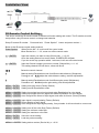
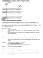
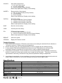
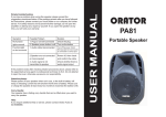
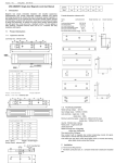
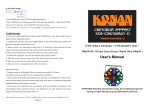
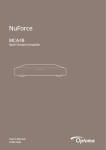
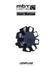
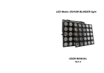
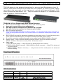
19" 1U Rack Mounting Auto Gain Multi Port Video Receiver Hub ITEM NO.: TPA016A TPA016A design by the advanced technology for auto gain and Equalization which 16 channel video active receiver to be install onto one compact 19” wide 1U panel, panels can reside in the same rack as other equipment , such as switchers, multiplexers, DVR, video conferencing equipment.. etc. They are perfect for larger CCTV installations and ideal for security monitoring stations. TPA016A 16 Port Digital Auto Gain Active Receiver Built in 16 port auto gain receivers in 1U 19” rack mounting panel. Auto gain control without any adjustment. Use with passive transmitter for distance up to 1.5KM. Use with active transmitter for distance up to 2.0KM. Built in transient protection. This device auto gain operation by factory default. For any abnormal picture occurred, it could be using RS485 terminal or IR remote control for advanced management setup and control. Built in RS485 terminal for advanced management setup and control. It could be daisy chain up to 32pcs of TPA016A by any one option remote/PC/mobile phone control. It could be control by mobile phone with using option model RS006: RS45 to Ethernet. Option model: RS003: USB to RS485 converter, RS001: RS232 to RS485 converter, RS005: RS232 to Ethernet converter, IR01: IR remote control Option model: 1) IR01 (IR remote control) ---- using IR control for advanced function setting. 2) RS003 (USB to RS485 converter)、RS001 (RS232 to RS485 converter) ---- using PC for advanced function setting. 3) RS006 (RS485 to Ethernet converter) ---- using Internet via PC/or mobile phone for advanced function setting. Panel view & Function: LED Indication: LED Color Status Function Power LED GREEN Channel LED BLUE On Flash On Flash Power Under Setting Video Signal Input Hardware Defective Installation View: TPA016A IR Remote Control Setting: This device could use IR remote control for advanced function setting and control, The ID number must be setup before using IR remote control or change new batteries. Setup IR remote ID number: Press and hold “Power Symbol" button and press number 1, Below is the IR remote control setting method: Power Symbol When Device No = 0, could on/off the control mode. When Device No = 1 – 32, mean turn off the control mode. * n ENTER Input the number you want to setup (Device No),n = 0-32, Once the setting device into control mode, POWER LED will flash, If you do not do any operation within 1 minutest, it will auto off control mode. # n ENTER Input the Channel number you want to control (Channel No), n = 1-16, The setting channel LED will be on, others will be off. 1111111 Select the control channel A Manual setting Equalization mode for different cable distance (Sharpness) Press A to use ▲ ▼ adjust the cable distance setting, total 64 adjustments. B Manual setting Equalization mode for different gain control (Brightness) Press B to use ▲ ▼ adjust the gain setting, total 64 adjustments. MENU 1 ENTER MENU 2 ENTER Setting auto gain mode (Factory Default) Setting manual Equalization mode. MENU 3 0 ENTER Setting input signal as color signal and make Equalization for color signal. MENU 3 1 ENTER Setting input signal as mono signal and make Equalization for mono signal. MENU 3 2 ENTER Auto recognize the format of input signal, and make its format. (Factory Default) MENU 4 0 ENTER Input signal is normal polarity (Factory Default) MENU 4 1 ENTER Revert polarity of input signal MENU 4 2 ENTER Auto recognize the input signal polarity, if any mistake. It will revert back to correct one. MENU 5 0 ENTER Setting turn off the noise filter.(Factory Default) MENU 5 1 ENTER Setting the minimum noise filter. MENU 5 2 ENTER Setting the maximum noise filter. MENU 6 ENTER MENU 7 ENTER Save the current setting. Load the previous setting. MENU 8 n ENTER Setting device number (Device No), n = 0-32 2 Function Setting & Management application: 32 Termination Resistors Function Setting & Management application: This device could use command line to control via built in RS485 terminal program, (CLI, Command-Line Interface), through RS485 terminal port (Console Port) for detailed function setup and management. You could use our model number: RS003 USB to RS485 converter, or RS001 RS232 to RS485 converter, the Communication format is 9600,8, N, 1 (9600 bps, 1 start bit, 8 data bits, 1 stop bit). Use command as below: ? Display command usage *n Control device number (Device No), n = 0-32, Without input parameter: Display the device number Once the setting device into control mode, If you do not do any operation within 1 minutest, it will auto off control mode. #n Control channel number (Channel No),n = 1-16, Without input parameter: Display current setting SET n Setting this device number, n = 0-32, 0 mean stand alone mode (Factory Default) Do not repeat setting the device number, recommend setting an individual connection to RS485, not to connect other devices in series in order to avoid any confusion at the setting number. STATUS n Display the current control device channel status n=0 display all channel status n = 1-16 display the specified channel status Without input parameter: Display current control channel status AUTO Setting auto gain mode (Factory Default) MANUAL Setting manual Equalization mode. LENGTH n Manual setting Equalization mode for different cable distance (Sharpness), n = 0-63 (Factory Default is 0),1 step equal 25 METERS. Without input parameter: Display current setting. GAIN n Manual setting Equalization mode for different gain control (Brightness), n = 0-63 (Factory Default is 32), 0 is the darkest value,63 is the brightness value. Without input parameter: Display current setting. 3 COLOR n Input video signal format n = 0 is mono video signal n = 1 is color video signal n = 2 auto recognize (Factory Default) Without input parameter: Display current setting. INVERT n Revert polarity of input signal n = 0 Do not revert polarity (Factory Default) n = 1 revert polarity n = 2 auto recognize Without input parameter: Display current setting. FILTER n Noise filter setting n = 0 turn off noise filter (Factory Default) n = 1 setting as the minimum noise filter n = 2 setting as the maximum noise filter Without input parameter: Display current setting. SAVE Save the current setting. LOAD Load the previous setting. IR n IR Remote Control setting n = 0 turn off IR remote control function n = 1 turn on IR remote control function (Factory Default) Without input parameter: Display current setting. REBOOT reboot the system VERSION Display the firmware version Trouble Shooting: 1. When control over one piece of TPA016A, each device must setting the individual Device Number to avoid any confusion or failed control and management. 2. Please remember save any new change/setting in order to operate the new setting correctly. 3. If using multiple TPA016A with RS485 series control, the last TPA016A device must add 120Ω termination resistors at terminal port (Console Port) in order to stabilize the data signal. 4. Long distance transmission or have interference occurred that might cause Equalization function not correct or not able to do auto gain correctly, even not able to lock auto gain. The picture occurred the “light and dark” alternating, recommend using manual Equalization setting for adjustment. 5. Long distance transmission or have interference occurred, the auto recognize signal polarity and color may be failed; recommend to use manual setting according the actual signal format. Specification: ITEM NO. Video Format Video Input Video Output Management Terminal Infrared IR control Receiving Power Consumption Power Adapter Dimension mm Weight g TPA016A NTSC / PAL 8 pin removable terminal x 4 (100 Ω,1.4 Vp-p) BNC x 16 (75 Ω,1 Vp-p) 2 pin removable terminal x 2 (RS485) ± 55° / 5 meters 750mA DC 12V 1A 483 x 183 x 44 (1U) Rev. A 4