1
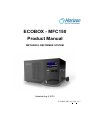
ECOBOX - MFC150
Product Manual
METHANOL REFORMER SYSTEM
Updated Aug 8, 2015
ECOBOX-MFC150_UM_V2.7
Disclaimer
This manual incorporates safety guidelines and recommendations. However, it is not intended to
cover all situations. It is the responsibility of the customer to meet all local safety requirements
and to ensure safety during operation, maintenance and storage of the ECOBOX-MFC150 system.
Although all efforts have been made to ensure the accuracy and completeness of the information
contained in this document, Horizon reserves the right to change the information at any time and
assumes no liability for its accuracy.
Actions that will void the fuel cell system warranty:
Attempting, under any circumstance, to disassemble or inappropriately tamper with the
system.
Disassembling the system.
Operating the system in a manner which is not anticipated in the system setup and/or
specified in the user manual provided for the specific product.
Damage to the system caused by misuse, physical abuse or neglect.
The ECOBOX-MFC150 system uses IMPCA-grade Methanol blend of 62.5% methanol, 37.5%
distilled, deionized and demineralized water by weight. If a purified Methanol Blended fuel is
not available in your location, please use only pure distilled water and IMPCA -grade Industrial
pure methanol to make it.
Do not attempt, under any circumstance, to disassemble or
inappropriately tamper with the system. There will be no repair,
replacement or refund should disassembly or tampering occur. If you
have questions or need help with regards to the system and its
technology,
please contact:
[email protected]
Copyright Horizon Fuel Cell Technologies – ECOBOX-MFC150_UM_V2.7
2
Table of Contents
Table of Contents .......................................................................................................................... 3
1. Important Safety Information................................................................................................ 4
1.1
1.2
1.3
1.4
1.5
1.6
1.7
General information ................................................................................................................4
Using Methanol.......................................................................................................................5
Handling Methanol..................................................................................................................6
Methanol Storage- Portable Containers (Totes and Drums) ......................................................6
Electrical Classification ...........................................................................................................7
Grounding and Bonding ..........................................................................................................8
Terminology ......................................................................................................................... 10
2. User Manual........................................................................................................................... 11
2.1
2.2
2.3
Introduction .......................................................................................................................... 11
About This Manual ............................................................................................................... 11
PEM Technology .................................................................................................................. 11
3. The ECOBOX-MFC150 System .......................................................................................... 12
3.1
3.2
ECOBOX-MFC150 Models .................................................................................................. 13
Chassis System Features........................................................................................................ 14
4. Operation ............................................................................................................................... 22
4.1
4.2
4.3
Methanol Connection ............................................................................................................ 23
Wire Connection ................................................................................................................... 23
Grounding ............................................................................................................................. 24
5. Applications Engineering ..................................................................................................... 25
5.1
5.2
5.3
Storage Requirements............................................................................................................ 25
Site Requirements ................................................................................................................. 25
Load Engineering .................................................................................................................. 25
Appendix A: ECOBOX-MFC150 Specifications ...................................................................... 26
Appendix B: ECOBOX-MFC150 Drawing............................................................................... 28
Copyright Horizon Fuel Cell Technologies – ECOBOX-MFC150_UM_V2.7
3
1. Important Safety Information
Please read all instructions carefully prior to product use and keep this manual with or near the
system for future reference.
The safety guidelines included here may not cover every situation. Use common sense and caution
at all times when working on or near the system.
DO NOT SMOKE in the vicinity of the system or the fuel.
DO NOT WELD in the vicinity of the system or the fuel.
DO NOT ALLOW ANY NAKED FLAME in the vicinity of the system or the fuel.
DO NOT DRINK the Methanol Fuel – it is a poison which WILL BLIND you and may KILL you.
Wear Personal Protective Equipment when handling the Methanol Fuel – Latex Gloves, Safety Eye
Protection and Class 2 face mask.
Although the Methanol reformer systems are designed with simple, easy-to-use interfaces,
prudent safety measures should be followed.
1.1 General information
For this unit to generate electrical power, a supply of methanol is necessary. It is important for any
operator to be aware of, understand, and follow all local safety requirements related to the
handling of methanol. Ensure that your facility conforms to all local regulatory requirements,
including building codes, storage and safety recommendations.
The methanol reformer system has built-in safeguards and is designed to shut down automatically
if any out of range operating condition occurs. Possible situations include low cell voltage, fuel
leakage, high temperature, and low fuel level.
Do not operate the system on a grade of more than 35 degrees.
Do not connect or disconnect power cables when the system is energized.
Do not move the system when the system is running.
Do not dismantle the system. Contact Horizon if you have any concerns about operation.
Copyright Horizon Fuel Cell Technologies – ECOBOX-MFC150_UM_V2.7
4
1.2 Using Methanol
The ECOBOX-MFC150 system uses 62.5% methanol, 37.5% distilled, de-ionised water. If you can
not access prepared fuel from your Horizon agent or a reliable local supplier, you can mix the fuel
yourself if you exercise caution. Contact your Horizon agent or the Methanol Institute for specific
instructions and training on safe management of the fuel mixing process.
Do not breathe the vapour, do not allow Methanol to contact with clothing or skin, do not ingest
or drink the methanol, and avoid any release into drains or waterways. Please use only distilled,
de-ionised water and Industrial pure methanol to make it.
Methanol Emergency Response - Medical and Safety
•
•
•
•
•
•
Symptoms of acute methanol exposure may include headache, weakness, drowsiness,
nausea, difficult breathing, drunkenness, eye irritation, blurred vision, loss of
consciousness, and possibly death.
Patients may appear to improve and then get worse again up to 30 hours later.
In case of methanol contact with skin, remove any contaminated clothing, wash with
soap and water for 15 minutes, and seek medical attention if irritation occurs.
If methanol comes in direct contact with eyes, immediately flush eyes with copious
amounts of tepid water for at least 15 minutes. The patient should be taken to a health
care facility and referral to an ophthalmologist considered.
In case of inhalation of methanol vapors, remove individual to fresh air. Asphyxiation
from vapors may require artificial respiration. Seek immediate medical assistance
Ingestion of methanol is life threatening. Onset of symptoms may be delayed for 18 to 24
hours after ingestion. If patient is conscious, immediately give two glasses of water and
induce vomiting. Do not make an unconscious person vomit. Transport immediately to a
health care facility where standard methanol ingestion treatment can be administered.
WARNING! FIRE OR EXPLOSION
Keep all sources of ignition away from Methanol.
Always operate the system in a well-ventilated area and ensure that ventilation slots are
unobstructed. Be aware of localized sources of combustion such as gas fired water heaters and
space heating units which can start on demand.
WARNING
The MFC150 uses methanol. Methanol is poisonous to humans. Less than 30ml (1oz) ingested or
swallowed may cause irreversible blindness and may kill a person.
Methanol is a colorless alcohol, hygroscopic and completely miscible with water, but much lighter
(specific gravity 0.8). It is a good solvent, but very toxic and extremely flammable. This simple
single-carbon alcohol is a volatile solvent and a light fuel.
Copyright Horizon Fuel Cell Technologies – ECOBOX-MFC150_UM_V2.7
5
The particular hazards of methanol that matter most to your facility depend in large part on how
methanol is received and stored, how it is used, where it is used, and how much is stored and used
at any given time. Failure to control hazards associated with a small amount of methanol can be
problematic with virtually no consequence; loss of control of a large quantity can be catastrophic.
1.3 Handling Methanol
WARNING
Do not handle methanol without training or experience.
Five overriding considerations are important when handing methanol:
Methanol is a toxin; ingestion of a small amount (between one and two ounces,
approximately 30 to 60 milliliters) may cause death; lesser amounts are known to cause
irreversible blindness. Do not swallow methanol liquid, and do not allow vapor or liquid to
contact skin. Methanol absorbs through the skin and other tissues directly into the blood
stream.
Methanol is a flammable, easily ignited liquid that burns and sometimes explodes in air.
The molecular weight of methanol vapor is marginally greater (denser) than that of air (32
versus 28 grams per mole). As a result, and depending on the circumstances of a release or
spill, methanol liquid will pool and vapor may migrate near the ground and collect in
confined spaces and low-lying areas. It is expected that methanol vapor, being nest neutral
buoyancy, will dissipate readily from ventilated locations. Do not expect it to dissipate from
non-ventilated locations such as sewers and enclosed spaces. If ignited, methanol vapor can
flash back to its source.
In certain specific circumstances, methanol vapor may explode rather than burn on ignition.
Methanol containers are subject to Boiling Liquid Expanding Vapor Explosion (BLEVE) when
heated externally.
Methanol is totally miscible in water and retains its flammability even at very high
concentrations of water. A 75% water and 25% methanol solution is considered to be a
flammable liquid. This has important consequences for firefighting. Methanol is a chemical
solvent, which has important implications for materials selection and also for firefighting.
1.4 Methanol Storage- Portable Containers (Totes and Drums)
Totes and drums can be problematic. The methanol industry has gone to considerable lengths to
design and fabricate satisfactory totes that are easily obtainable. Because the number of users of
tote and drums far outnumbers the number of facilities with dedicated bulk storage and handling
systems, this manual stresses the importance of safe methanol handing for tote and drum
containment. It is strongly suggested that handlers consult methanol providers concerning their
selection of containment. Unlike tank farms, where personnel seldom have direct contact, users of
totes and drums are typically subject to spillage, need for immediate response, and subsequent
cleanup.
The following provisions are suggested for tote, drum, and can users:
Copyright Horizon Fuel Cell Technologies – ECOBOX-MFC150_UM_V2.7
6
Methanol should be purchased only from reputable sources.
Providers should be consulted regarding the intended application and circumstances of use
before committing to a sales contract. Many merchant chemical companies are equipped and
willing to extend their services in order to assure safe use of the chemicals they sell.
After agreeing on facilities and provisions for receiving, storage, and local transfer, establish
and train a local response team in the actions that are necessary and prudent in the event of a
spill.
Certain aspects of methanol handing require special provisions and protective measures.
These include the following:
As much as possible, methanol should be stored and used in a dedicated area that is
specifically marked off and appropriately labeled. This area should have safety measures
readily available to employees working in the area. The area should be designated as a
hazardous area, and protective measures should be immediately available in the event of
spillage, exposure, and ignition.
The area designated for methanol handing should be equipped with an effective audible
alarm, which will summon assistance in a timely manner.
Use positive materials identification for gaskets, filters, hose material, and similar supplies
which will be in contact with the Methanol fuel.
Replace gaskets, hoses, and “O” rings periodically, before they are expected to degrade or
fail.
Ensure that procedures are in place to ground Methanol tanks and containers, and
periodically verify grounding.
Ensure that procedures are in place to protect against water uptake and accumulation.
Ensure that provisions and procedures are in place to prevent spilled methanol from
entering drains, manholes, and confined spaces.
Ensure that procedures and provisions are in place for preventing methanol entry into the
water table or aquifers.
Ensure that procedures and equipment are in place for personnel protection and
exposure mitigation. This should include eye wash and shower stations.
Ensure that procedures and equipment are in place for leak detection and alarm.
Ensure that procedures and equipment are in place for onsite emergency response.
Ensure that procedures and possibly specialized equipment are in place for offsite
emergency responders.
1.5 Electrical Classification
Electrical equipment within the proximity of methanol storage and handing must be explosion
proof to meet National Electrical Code (NEC) requirements [42]. Positive pressure may be required
to ensure that methanol-free areas, such as smoking rooms and control systems and electrical
switch gear, are protected.
Copyright Horizon Fuel Cell Technologies – ECOBOX-MFC150_UM_V2.7
7
1.6 Grounding and Bonding
Grounding is especially important in protecting methanol from accidental ignition resulting from
static discharge. Methanol is polar compound. In general, methanol storage is not expected to
accumulate static charge. However, circumstances such as a tank with a non-conductive liner can
change the rate of charge accumulation.
It is recommended that grounding straps be equipped with carbide-tipped clamps to ensure
electrical contact through nonconductive surface coatings, such as paint. Tanks and storage vessels
should be fitted with dip-tube-filling to protect against ignition from static electricity generated as
a result of liquid falling through air.
Grounding is required for lighting systems, pipe racks, pumps, vessel, filters, and all other
equipment near and potentially within range of methanol vapor. Tall towers and other equipment
subject to lighting strike must be equipped with lightning arresters.
Hoses must be grounded. In methanol loading and unloading situations, the possibility of spark
generation due to accumulation of static electricity is less than with materials such as low sulfur
diesel. Methanol is not a static accumulator. Electrical conductivity of methanol is relatively high
when compared to that of most fuel materials. Nevertheless, velocity limits should be placed on
transfer operations that involve high pressure drop, hydraulic impacts, and erosion concerns.
Refer to API and NFPA publications for specific guidance.
Bonding is a measure intended to dissipate static electricity generated during fluid transfer
through a conductive or nonconductive material. It involves making a connection between a
grounded object and an ungrounded object. Methanol transfer operations should be bonded and
grounded.
Metal containers (drums or totes) and the associated fill equipment pump should be bonded
together and grounded during methanol transfer operations. Fill pipes or hoses should be
conductive and should be bonded to the filling system. Bonding should be done with a 1/8-inch
bare stainless steel cable connected to a clamp with hardened steel points and screws or a strong
spring that will penetrate paint, corrosion, and accumulated materials. Apply the bonding clamp
on the top chime of drum containers prior to removing the bung. Extend the pipe to within one
inch (25 mm) of the bottom of the container. Start pouring slowly (at less than one meter per
second or a container fill rate of less than 2 inches or 5cm of fluid level rise per minute) until the
container is filled to a level equivalent to two pipe diameters up the side of the fill pipe.
In recent years, attention has been drawn to the hazard of using personal electronic items, such as
cell phones, laptop computers, etc., in environments subject to potentially explosive atmospheres,
e.g., gasoline stations, and fueling terminals. The energy necessary to ignite gasoline vapors (0.2mJ
at the optimum mixture ratio for combustion) is similar to the energy produced by static electricity
Copyright Horizon Fuel Cell Technologies – ECOBOX-MFC150_UM_V2.7
8
and by sparks generated by low-voltage electrical devices when they are turned on. It is not
considered good practice to operate electronics such as cell phones and laptop computers in a
potentially flammable atmosphere.
Be aware of the following:
Mobile phones can ignite fuel fumes from gasoline, ethanol, methanol, propane, and
compressed natural gas (CNG).
Mobile phones that light up when switched on or when they ring release enough energy to
provide a spark capable of igniting hydrocarbon vapors.
Mobile phones should not be used (should be turned off) in filling stations, fuel terminals, or
when filling portable containers, fueling lawn mowers, boats, etc.
Mobile phones should not be used (should be turned off) around materials that generate
flammable or explosive fumes (e.g., solvents, chemicals, gases).
The same precautions apply for laptop computers, flashlights, battery lanterns, and other batteryoperated devices should not be used within 20 feet (7 meters) of a potentially explosive
atmosphere. This distance is sufficient to provide a buffer of distance between the potential
source of ignitable fumes and the device. Increase this distance to 50 feet (17 meters) for
pressurized liquid gases, such as propane.
When dispensing from a metal container, the container and the associated fill equipment,
including dip pipes, conductive hose, and pump, should be bonded together and grounded. Plasticlined metal containers with epoxy or phenolic coatings less than 2mm thick can be treated as
metal containers. If the liner is more than 2 mm thick, the container should be treated as nonconductive. When handing methanol, treat non-conductive containers as if both the container and
the methanol are non-conductive.
Plastic containers cannot be grounded and should not be used for Class I Flammable liquids, such
as methanol, without expert review, as per NFPA 30, Flammable and Combustible Liquids. If a
plastic container must be used, follow the same procedure as for metal containers.
Copyright Horizon Fuel Cell Technologies – ECOBOX-MFC150_UM_V2.7
9
1.7 Terminology
PEM fuel cell:
A PEM (Proton Exchange Membrane) fuel cell is a device that converts hydrogen and oxygen into
water and electricity.
Reactants:
Reactant is a material used to start a chemical reaction. In the fuel cell the reactants are air and
hydrogen by which the electricity will be generated.
Humidification:
Humidity, the fuel cells need a certain level of Humidity for running.
Blower:
Supply air to the fuel cells and meanwhile decrease the temperature in the stack.
Mass flow per minute:
The total amount of the hydrogen flow through the fuel cell every minute, which the hydrogen
supply can be calculated.
HFCT:
Horizon Fuel Cell Technologies
Copyright Horizon Fuel Cell Technologies – ECOBOX-MFC150_UM_V2.7
10
2. User Manual
2.1 Introduction
Thank you for choosing Horizon’s ECOBOX-MFC150 METHANOL REFORMER SYSTEM as your power
generating solution. Based on Horizon’s expertise in modular, redundant fuel cell systems, the
ECOBOX-MFC150 is the next step in simplicity, scalability, modularity and reliability, providing
clean, quiet, and reliable power for backup power applications.
2.2 About This Manual
This manual is intended to provide customers with all the information needed to select, install,
operate, maintain, and troubleshoot an ECOBOX-MFC150 system.
2.3 PEM Technology
While there are a number of fuel cell technologies available, the most common and practical
technology for standby power is the proton exchange membrane, or PEM, fuel cell.
The only inputs to the fuel cell are industrial Grade 3.5 hydrogen (99.95% H2 concentration) and
oxygen (air), with the only byproducts being pure water/vapor and heat. As a result, fuel cells are
considered a green technology, making them an attractive solution for installations with emissions
restrictions.
One of the other attributes of a fuel cell that makes it attractive for deployment in many
applications is that a fuel cell produces DC power. This makes a fuel cell akin to a standby rectifier
source, as the power provided from the fuel cell can be directly connected to the site’s DC power
bus. In an outage situation, the fuel cell turns on automatically, providing DC power, which was
formerly provided by the rectifiers. DC output also makes the fuel cell ideally suited for hybrid
applications with solar (photovoltaic), wind and battery systems.
The fuel cell is akin to a generator, in that the fuel cell is sized for the power requirement, and can
run indefinitely provided it has a source of fuel. This means fuel cells, when coupled with an
appropriately sized fuel storage solution, can function effectively for long reserve times as a
standby power source in customer applications.
Copyright Horizon Fuel Cell Technologies – ECOBOX-MFC150_UM_V2.7
11
3. The ECOBOX-MFC150 System
This section describes the operating principles of the ECOBOX-MFC150 system. The ECOBOXMFC150 system functions as a Methanol fueled Hydrogen Fuel Cell generation DC power source.
The unit can be started and stopped manually or automatically. Because its electrical output is DC,
the ECOBOX-MFC150 system can be installed directly in parallel with other DC equipment. The
systems are available in a range of 11V to 14V DC version.
For proper operation, the ECOBOX-MFC150 system requires airflow. A source of clean air must be
supplied. The exhaust air is humid, which may condense on cooler surfaces, and may contain trace
hydrogen and CO2, and therefore should be vented outdoors. There is a small periodic fuel purge
(or “bleed”) that must also be vented outdoors. A minimum installation for basic operation
requires the ECOBOX-MFC150 system to have all air exhausts and fuel inlet and outlet exhaust
connections plumbed, and that the unit is connected to a DC bus at the appropriate voltage, with
an appropriate load and suitable battery attached. A complete installation will include protection
from weather and temperature. The system can be supplied mounted in an optional IP54 rated
outdoor enclosure by Horizon. Horizon outdoor enclosures are specifically designed to house the
fuel cell equipment and provide proper protection from weather and temperature.
Table 3-1 shows the specification of ECOBOX-MFC150 system. For detailed specifications, please
see Appendix A.
Model
ECOBOX-MFC150
Table 3-1 ECOBOX-MR Specifications
Rated Power
Output Voltage
150W
11V to 14V
Detail Information
Appendix A
In a chassis-only configuration, the ECOBOX-MFC150 system is rated for indoor installation only.
Indoor installations must be ventilated to outdoors.
For outdoor installation, the ECOBOX-MFC150 system may be mounted in a 19” or 23” 2-post rack
or 4-post rack, which should be rated to IP54 or better.
In both indoor application and outdoor application, ECOBOX-MFC150 system must be kept away
from flammable and explosive goods and places (such as the gas station), and the sewer drainage
outlet, and chemical plants which may produce harmful gases, etc.
Locations where there is a high concentration of airborne pollution from traffic or industry, and
particularly diesel or chemical fumes, should be avoided where possible; additional filtering of the
incoming air should be used where such locations can not be avoided.
Copyright Horizon Fuel Cell Technologies – ECOBOX-MFC150_UM_V2.7
12
3.1 ECOBOX-MFC150 Models
The front panel of ECOBOX-MFC150 system, please see figure3-1.
Figure 3-1. The front panel of ECOBOX-MFC150
The rear panel of ECOBOX-MFC150 system, please see figure3-2.
Figure 3-2. The rear panel of ECOBOX-MFC150
WARNING
The temperature of Reformer Exhaust Outlet may reach 100 degrees. Please pay attention to
safety.
Copyright Horizon Fuel Cell Technologies – ECOBOX-MFC150_UM_V2.7
13
3.2 Chassis System Features
WARNING
To avoid property damage, personal injury or loss of life, DO NOT attempt to operate this unit until
all directions have been read and understood.
3.2.1 LCD Display
Figure 3-3. The LCD Display
3.2.1.1 ON/OFF button
Press the button for 1 second to power on the system.
After starting, press the button for 1 second to let the system enter to Hot Standby mode.
During Hot Standby, press the button for 1 second to let the system enter to normal operation.
Press the button for 3 seconds to shut down the system.
During shutting down, push the button for 5 seconds to restart the system.
3.2.1.2 LED Indicator Light
Green:
Lit during the normal operation.
Flash during starting and Hot Standby mode.
Red:
Lit when error happens.
3.2.1.3 Direction Key and Enter
The direction key and enter can be used to set the system mode.
The up and down key can be used to check the information during the normal operation.
3.2.2 LCD display information
System operation status display
System fault information
If the system shut down because of an error, The LCD will continue to show the error
information for 3 minutes. After 3 minutes, system will restart again automatically.
Stack and battery parameter display
Copyright Horizon Fuel Cell Technologies – ECOBOX-MFC150_UM_V2.7
14
Table 3-2 Fault information
Display
Note
The stack voltage is
lower than
<0.5V/Cell.
The stack current is
over 20A.
Solutions
a) Check fuel level.
b) Keep enough fuel supply.
The stack temperature
is over 68 degrees.
a) Avoid operating in an
overheated environment.
The battery voltage is
lower than 10.5V.
a) Check the battery voltage. The
voltage should between 12V to
14V.
b) Charge the battery by an
external power supply then
restart.
a) Check fuel level.
b) Restart system.
The buffer tank
presser is lower than
0.3bar.
The buffer tank
presser is higher than
8bar.
Hydrogen leakage
occurs in the system.
a) Turn off the system and restart.
a) Operate in a ventilated
environment.
The reformer
temperature is higher
than 610 degrees.
The reformer
temperature is higher
than 600 degrees.
The reformer
temperature is lower
than 2 degrees.
The reformer
temperature is lower
than 350 degrees.
The catalyst pressure
is higher than 20Bar.
a) Avoid operating in an
overheated environment.
The catalyst pressure
is lower than 2Bar.
a) Check fuel level
b) Keep enough fuel supply
c) Keep fuel hose unhindered.
a) Avoid operating in an
overheated environment.
a) Check the battery voltage. The
voltage should between 12V to
14V.
a) Check the battery voltage. The
voltage should between 12V to
14V.
Copyright Horizon Fuel Cell Technologies – ECOBOX-MFC150_UM_V2.7
15
The purifier
temperature is higher
than 460 degrees.
The purifier
temperature is higher
than 450 degrees.
The purifier
temperature is lower
than 2 degrees.
The purifier
temperature is lower
than 320 degrees.
The storage fault.
Load protection. Load
was shut down when
two errors happen
together.
Catalyst heating time
is more than 90
minutes when cold
starting. Catalyst
heating time is more
than 60 minutes when
warm starting.
Pressure rising time is
more than 30 minutes.
Catalyst heating time
is more than 20
minutes when system
restart automatically
for periodic
maintenance.
a) Avoid operating in an
overheated environment.
a) Avoid operating in an
overheated environment.
a) Check the battery voltage. The
voltage should between 12V to
14V.
a) Check the battery voltage. The
voltage should between 12V to
14V.
a) Check the battery voltage. The
voltage should between 12V to
14V.
a) Check fuel level
b) Check tank is not under
vacuum
c) Keep fuel hose unhindered.
a) Check the battery voltage. The
voltage should between 12V to
14V.
If you have questions or need help with regards to the fuel cell and its technology contact:
[email protected].
Copyright Horizon Fuel Cell Technologies – ECOBOX-MFC150_UM_V2.7
16
3.2.2.1 System Starting Process
Press the ON/OFF button to start the system, then the LCD display shows the system starting
information (Welcome to Horizon, the firmware version number…). Press ENTER to continue when
there was an error last time. The detailed system starting process please find in figure 3-4.
Figure 3-4. System starting process
Copyright Horizon Fuel Cell Technologies – ECOBOX-MFC150_UM_V2.7
17
3.2.2.2 Set System Mode
During the starting process, the customer can set the system mode. The ECOBOX-MFC150 system
has two modes; Auto Mode, and Manual Mode. Use direction keys to choose the system mode
setting. Press ENTER to enter into the system mode. Then use the direction keys and ENTER button
to choose and set the mode. The detailed system mode setting process can be looked in figure 3-5.
If there is no action within 5 seconds, the system will use the value which was set last time, and
enter to the next step automatically.
Figure 3-5. System Mode Setting Process
System mode setting
There are two modes which are Auto Mode and Manual Mode. The customers can press left or
right key to choose the system mode.
When setting the values in “Low Voltage Start”, “High Voltage Limit” and “Float Charge Period”,
press Enter to let the cursor appear, and then use direction keys to choose and change the value.
1) Auto Mode
When the system starts in Auto mode, the unit will attempt to achieve an output voltage
which is the value set in the “High Voltage Limit”. Once the system has achieved and held
float voltage for a period of time (set in the “Float Charge Period”), the unit will return to
Standby. This mode functions as a battery charge mode, charging up an external battery
Copyright Horizon Fuel Cell Technologies – ECOBOX-MFC150_UM_V2.7
18
to the “High Voltage Limit”, and then returning to Hot Standby. When the batteries
discharge to the “Low Voltage Start”, the system will start again. This charge/discharge
method is useful for very small loads, where the battery is properly sized to support the
small load, and is recharged by the fuel cell. The fuel cell system will operate
“thermostatically”, turning on at the “Low Voltage Start”, and turning off after holding the
output at the “High Voltage Limit” setting until the “Float Charge Period” expires. When
the bus voltage is held at or above the “High Voltage Limit” setting until the “Float Charge
Period” expires, the unit will return to Standby and remain there, provided the bus
voltage remains above the “Low Voltage Start”.
Auto mode is a useful option for off-grid hybrid systems that are relatively low power. The
fuel cell is used to charge the batteries, and the batteries then carry the load for extended
periods. The total system solution is most efficient for small loads that are <5% of the fuel
cell capacity, with an appropriately sized battery.
When started in Auto mode, the fuel cell will deliver power until the output bus voltage
reaches the user-set “High Voltage Limit” (whether because the unit has sufficient power
to support the load and charge the batteries, or because the external power was
restored). Once the “High Voltage Limit” is achieved, a user-adjustable “Float Charge
Period” will start. When the “Float Charge Period” expires, the unit will stop delivering
power and return to Standby.
“Low Voltage Start” in the user interface is used to set the voltage at which the system
begins to operate when the Auto Mode is enabled. This voltage must be at least 0.5V
below the value set in “High Voltage Limit”.
The “Low Voltage Start” range is from 11V to 13V.
“High Voltage Limit” in the user interface is used to set the voltage at which the system
returns to Standby.
And the range of “High Voltage Limit” is from 13.5V to 14V.
“Float Charge Period” in the User Interface is used to set the timer that determines the
end of the Auto mode.
“Float Charge Period” can be set from 0 to 200 minutes in 1 minute increments.
2) Manual Mode
When the system starts in manual mode, the system will keep running, and use the
minimum current to float charge the battery. The front panel ON/OFF switch allows the
user to manually turn the system on to generate power or to hot standby. And the only
method to stop the unit is by pressing the switch again.
Copyright Horizon Fuel Cell Technologies – ECOBOX-MFC150_UM_V2.7
19
3.2.2.3 Operation Information
Table 3-3 Operation information
System phase
Display
Note
System starting process
Startup
Normal
operation
Standby phase
Press down key to check system information.
“T” means temperature.
“B380” means burner temperature is 380℃.
“P320” means purifier temperature is 320℃.
“C385” means catalyst temperature is 385℃.
“P” means pressure.
“H0.50” means hydrogen pressure is0.50Bar.
“C00.9” means pump pressure is 00.9Bar.
“BAT” means battery. And the followings
are the battery voltage and current.
“STK” means stack. And the followings are
the stack voltage and current.
“BAT” means battery.
“T” means temperature.
“B380” means burner temperature is 380℃.
“P320” means purifier temperature is 320℃.
“C385” means catalyst temperature is 385℃.
“P” means pressure.
“H0.50” means hydrogen pressure is0.50Bar.
“C00.9” means pump pressure is 00.9Bar.
Hot Standby
“BAT” means battery. And the followings
are the battery voltage and current.
Shut down
phase
Shutdown
Press down key to check system information.
Alarm interface
To remind methanol solution level low alarm
message. It will not shut down the system
Press Enter to clear the alarm and continue
operating.
Copyright Horizon Fuel Cell Technologies – ECOBOX-MFC150_UM_V2.7
20
3.2.3 Air flow
The ECOBOX-MFC150 system filtered air inlet is on the front panel of the chassis. The unit’s air
exhaust is on the rear panel of the chassis.
An indoor rack installation should include room ventilation with sufficient filtered make-up air to
provide adequate airflow to the unit. The system exhaust area should be always kept clear of
debris and any flammables, and must be well ventilated to outside.
The ventilation system should be inspected annually and maintained free of obstruction for proper
venting.
An indoor rack installation should include room ventilation with sufficient filtered make-up air to
provide adequate airflow to the unit. And the air exhaust area should be always keeping fluent.
Either in an indoor rack installation, or a closed cabinet (indoor or outdoor), the air exhaust must
be ducted outside to prevent the accumulation of humid air, which can condense on cooler
surfaces.
3.2.4 DC Output +/The ECOBOX-MFC150 system should not connect to the load directly. You should connect to the
load with a battery in the circuit. The battery provides capacity for load-following, and also enables
some on-board functions to operate more rapidly during start-up.
WARNING
DC terminals should always be considered electrified when connected to a DC bus.
Observe proper polarity when connecting the power leads.
3.2.5 Circuit Breaker
The DC wires of ECOBOX-MFC150 system is provided with a circuit breaker that disconnects the
unit from the bus. The high current draw which is over 60A will open the circuit breaker.
3.2.6 Fuel Level Sensor Connector
The ECOBOX-MFC150 system is provided with a fuel level sensor connector in the front panel that
connects with the fuel tank to detect the fuel level. When the fuel level becomes too low, the
sensor will send the signal to ECOBOX-MFC150 system, and the LCD display will show alarm
information. However a low level alarm will not stop the unit operation, only showing in the LCD
display. Press ENTER to clear the alarm information, and replenish the fuel.
Copyright Horizon Fuel Cell Technologies – ECOBOX-MFC150_UM_V2.7
21
4. Operation
WARNING
To avoid property damage, personal injury or loss of life, DO NOT attempt to operate the ECOBOXMFC150 system until all directions have been read and understood.
Please use only IMPCA- grade pure methanol and de-ionised, demineralised distilled water for the
fuel. The concentration by weight is 62.5% Methanol to 37.5% pure water.
When handling the Fuel, please keep the workplace well ventilated, clear of all sources of ignitions,
spark or flame, avoid any contact with the Methanol fuel, use personal protection (gloves,
breathing mask, Safety Glasses, long sleeves etc) to protect and prevent contact with the skin and
eyes, and avoid breathing the vapours.
Check the integrity of the fuel lines before filling the tank, and pay careful attention to the
connections to avoid any leakage. Check the fuel level in the tank and the fuel lines before running
the system.
When running, the unit will operate in a similar way to a power-limited voltage source. The unit
will supply power, attempting to achieve the output voltage. If the power limit of the unit is
reached before the output voltage is achieved, the system will sustain its maximum power output.
This maximum power output limitation may, for example, be at the rated value or less, due to
temperature, altitude, reduced airflow (due to restrictions of intake or exhaust flow), reduced fuel
flow (due to regulator pressure or hydrogen bleed obstruction), or fuel cell aging.
From start-up, a properly maintained ECOBOX-MFC150 system in heated standby will achieve 60%
power in approximately one minute and peak power in approximately 10 minutes at 20°C at sea
level. If heated standby off (system cold start), it will need 30 minutes more. This warm-up period
is required for the fuel cell to heat itself sufficiently to evaporate the water created during the
electrochemical process of making electricity and water from hydrogen and oxygen. Though the
fuel cell could make full power almost instantly, doing so while cool would cause water to
accumulate within the fuel cell, preventing gaseous hydrogen and oxygen (air) from reaching the
reaction surfaces. Therefore, the system is controlled to make as much power as possible while
allowing the water generated by the reaction to be evaporated to the atmosphere.
Copyright Horizon Fuel Cell Technologies – ECOBOX-MFC150_UM_V2.7
22
4.1 Methanol Connection
The fuel tank level should be at the level of the Methanol intake port. The fuel lines should be
filled with methanol mix, and should have no air bubbles. DO NOT RUN THE PUMP DRY or with
significant quantity of air in the lines, or the pump may be severely damaged.
4.2 Wire Connection
Figure 4-4 illustrates the detailed wiring connections for an indoor ECOBOX-MFC150 system
installation.
Figure 4-2. ECOBOX-MR25S1 system wiring connections
The minimum recommended external battery capacity for use with the ECOBOX-MFC150 system is
one 100Ah lead acid battery for a 12V installation. This provides adequate buffering for system
start-up and load fluctuations, and ensures protection for the battery string against over-discharge.
The startup time will be 25 to 35 minutes when using lead acid battery, depending on ambient
temperature.
Copyright Horizon Fuel Cell Technologies – ECOBOX-MFC150_UM_V2.7
23
4.3 Grounding
Using acceptable practices, as specified by NFPA 70 and National Electrical Code 250.166, connect
a chassis ground wire to the chassis ground terminal provided on the ECOBOX-MFC150 system
rear panel (Refer to Figure 4-3), and the screws on the rear panel of ECOBOX-MR25S1 stack can be
identified as the chassis ground terminal(Refer to Figure 4-4). The ground wire size shall be a
minimum of 10 AWG.
Figure 4-3. Grounding on controller
Copyright Horizon Fuel Cell Technologies – ECOBOX-MFC150_UM_V2.7
24
5. Applications Engineering
This section provides information to assist with the selection of the best-suited ECOBOX-MFC150
system configuration for the desired application. It also outlines site considerations for optimal
fuel cell performance.
5.1 Storage Requirements
The ECOBOX-MFC150 system requires periodic operation or exercise in order to maintain proper
hydration of the fuel cell stack. Horizon recommends that the ECOBOX-MFC150 system should
operate at least 30 minutes per month. When not in operation, the system should be stored in
controlled environments.
5.2 Site Requirements
WARNING
To avoid fire hazards, do not locate the fuel cell system next to stored gasoline or other flammable
vapors and liquids. The system should have clear and clean airflow available, and the air intakes
must not be restricted or the system may overheat or function in a derated condition due to overtemperature.
5.3 Load Engineering
When sizing the application both the actual site load and any additional heater load within the
ECOBOX-MFC150 system due to cold environments should be considered. Site load should be
determined by measuring the actual DC power output of the rectifiers during normal operation.
Name-plate ratings of equipment should not be used to determine power requirements.
Copyright Horizon Fuel Cell Technologies – ECOBOX-MFC150_UM_V2.7
25
Appendix A: ECOBOX-MFC150 Specifications
ECOBOX-MFC150 Technical Specifications
SYSTEM SPECIFICATION
Power Rating
Voltage Adjustable
Voltage ripple
Controller Dimension(WxDxH)
Base Footprint(WxD)
Total Weight
Enclosure Material
OPERATION
Power Conditioning
Cold Start Time Required
Cold Start Power Requirements
Hot Standby Power Consumption
Hot Standby Start Time
Fuel Consumption
(Methanol/Water mix)
EMISSIONS
Reformer exhaust
Noise
Water
CO, NOx, SOx
FUEL CELL SYSTEM
Type
Coolant
Efficiency
Fuel Type & Specification
Methanol Quality Requirements
Water Quality Requirements
Hydrogen Purity Delivered
Fuel Storage
OPERATING ENVIRONMENT
Operating Temperature Range
Relative Humidity
ECOBOX-MFC150
0 to 150 W @ 20°C and 101.3 kPa
11-14 V DC
±1V
470mm x 370mm x 300mm
470mm x 370mm
16.1 kg
Galvanized steel plate, powder-coated
DC/DC converter
Approximately 30 minutes from 20C ambient temperatures
12 VDC, 400W for less than 25mins
15W
Less than 5 minutes
1.2L/KWH (62.5% Methanol)
CO2/H2 by-product, must be properly vented to outside
atmosphere
<30 dBA@ 1m
Approx 0.38L/kWh dependent on conditions, condenser kit
available
None
PEM
Air
55% peak operating for fuel cell power module
Methanol-Water mix. Mix ratio: 62.5% methanol, 37.5%
deionized water by weight
99.85% purity, recommend Methanol compliant with IMPCA
Specifications
Deionized water
99.99% pure hydrogen
External to System; Suitable Liquid Drums or Tanks
Start temperature range, rated power maintained -10 to 35C
0 to 95 % non-condensing
Copyright Horizon Fuel Cell Technologies – ECOBOX-MFC150_UM_V2.7
26
Recommended Altitude
Shipping Freeze Exposure
Usage
CONTROLS & COMMUNICATION
Software
Built-in User Interface
Built-in User Interface
Connectivity
<1,000 meters, 3280 ft
Fuel cell stack non-operating / shipping exposure limit: -20C
Indoor/Outdoor stationary
Standard 76mm LCD & Keypad
Standard 76mm LCD & Keypad
Serial port RS232, connect to computer, optional
Copyright Horizon Fuel Cell Technologies – ECOBOX-MFC150_UM_V2.7
27
Appendix B: ECOBOX-MFC150 Drawing
Copyright Horizon Fuel Cell Technologies – ECOBOX-MFC150_UM_V2.7
28