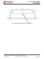
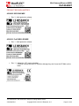
1
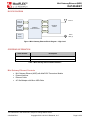
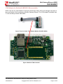
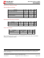
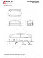
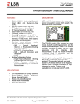
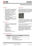
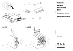
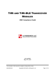
Mini Gateway Ethernet (MGE) DATASHEET Mini Gateway Ethernet for ModFLEX Wireless Networks FEATURES DESCRIPTION Compatible with all modules in the ModFLEX family Ethernet Interface: o RJ-45 connector o 10/100Mbps data rate LM3S6911 ARM Cortex M3 processor Small package size: 2.3” x 4.9” External high performance antenna External 5V power supply (Micro USB interface) Accessible micro-SD card interface Embedded TCP/IP Web Server APPLICATIONS Lighting Control Sensor Networks Security HVAC Control Medical Smart Energy The Mini Gateway Ethernet (MGE) is a device that allows you to access your wireless network through an Ethernet interface, and supports the use of a ModFLEX module. The wireless module in the MGE can be commanded and controlled through a IP connection using the module’s host protocol. In addition the MGE comes with an internal web server that can be accessed by any PC with an Ethernet connection. The web server can be customized via a programming development environment. Need to get to market quickly? Not an expert in wireless? LS Research design services would be glad to develop a custom hardware or software solution for you. Contact us at [email protected] or call us at 262-375-4400. The information in this document is subject to change without notice. 330-0066-R2.0 Copyright © 2011-2012 LS Research, LLC Page 1 of 22 Mini Gateway Ethernet (MGE) DATASHEET BLOCK DIAGRAM Ethernet Interface Antenna UART JTAG micro-SD Card Interface LM3S6911 TI Microcontroller ModFLEX Module GPIO Status LEDs (3) Power Supply Figure 1 Mini Gateway Ethernet Block Diagram – High-Level ORDERING INFORMATION Order Number Description 450-0025 ModFLEX MGE with SiFLEX02 Module 450-0101 ModFLEX MGE with ProFLEX01-R2 Module Table 1 Mini Gateway Ethernet Model Numbers Mini Gateway Ethernet Contents Mini Gateway Ethernet (MGE) with ModFLEX Transceiver Module External Antenna Ethernet Cable AC Wall Adapter with Micro USB Cable The information in this document is subject to change without notice. 330-0066-R2.0 Copyright © 2011-2012 LS Research, LLC Page 2 of 22 Mini Gateway Ethernet (MGE) DATASHEET TABLE OF CONTENTS FEATURES .......................................................................................................................... 1 APPLICATIONS ................................................................................................................... 1 DESCRIPTION ..................................................................................................................... 1 BLOCK DIAGRAM ............................................................................................................... 2 ORDERING INFORMATION ................................................................................................ 2 Mini Gateway Ethernet Contents ............................................................................................................... 2 GATEWAY OVERVIEW ....................................................................................................... 5 Microcontroller ............................................................................................................................................ 5 ModFLEX Module ........................................................................................................................................ 6 Antenna ........................................................................................................................................................ 6 FEATURES .......................................................................................................................... 7 Base Application ......................................................................................................................................... 8 light weight IP (lwIP) Stack......................................................................................................................... 9 Web Server ................................................................................................................................................ 10 FreeRTOS ................................................................................................................................................... 10 FatFs ........................................................................................................................................................... 10 Host ............................................................................................................................................................ 10 DEVELOPMENT TOOLS ................................................................................................... 11 IAR Embedded Workbench for ARM (EWARM) ..................................................................................... 11 J-Link Debugger ........................................................................................................................................ 11 Olimex ARM-JTAG-EW Debugger ........................................................................................................... 11 JTAG Adapter for Stellaris® LM3S6911 Microcontroller ...................................................................... 13 UPDATING FIRMWARE ON MODULE ............................................................................. 14 ELECTRICAL SPECIFICATIONS ...................................................................................... 15 Absolute Maximum Ratings ..................................................................................................................... 15 Recommended Operating Conditions .................................................................................................... 15 Power Consumption ................................................................................................................................. 15 SHIPPING, HANDLING, AND STORAGE ......................................................................... 16 Shipping ..................................................................................................................................................... 16 Handling ..................................................................................................................................................... 16 The information in this document is subject to change without notice. 330-0066-R2.0 Copyright © 2011-2012 LS Research, LLC Page 3 of 22 Mini Gateway Ethernet (MGE) DATASHEET Storage ....................................................................................................................................................... 16 AGENCY STATEMENTS ................................................................................................... 17 SiFLEX02 .................................................................................................................................................... 17 ProFLEX02-R2 ........................................................................................................................................... 17 AGENCY CERTIFICATIONS ............................................................................................. 18 EUROPE – PROFLEX01-R2 .............................................................................................. 18 CE Notice ................................................................................................................................................... 18 Declaration of Conformity (DOC) ............................................................................................................ 18 MECHANICAL DATA......................................................................................................... 19 PRODUCT REVISION HISTORY ....................................................................................... 21 CONTACTING LS RESEARCH ......................................................................................... 22 The information in this document is subject to change without notice. 330-0066-R2.0 Copyright © 2011-2012 LS Research, LLC Page 4 of 22 Mini Gateway Ethernet (MGE) DATASHEET GATEWAY OVERVIEW The MGE provides a pass-through capability for applications that require connectivity between a wireless network and an Ethernet network. Command and control of the module is achieved through the host protocol commands. See the MGE Host Protocol guide for more details. These These commands can also be exercised though the ModFLEX Test Tool Suite. The internal software architecture of the MGE consists of the following: FreeRTOS (Operating System) lwIP (light weight IP Stack) FatFs (FAT File System) HTTP Web Server ModFLEX Module Driver Microcontroller The MGE uses the Stellaris® LM3S6911 microcontroller from Texas Instruments. The Stellaris® LM3S6911 microcontroller is based on the ARM® Cortex™-M3 controller core operating at 50 MHz, with 256 kB single-cycle flash, 64 kB single-cycle SRAM, 10/100 Ethernet MAC/PHY. Figure 2 LM3S6911 Block Diagram The information in this document is subject to change without notice. 330-0066-R2.0 Copyright © 2011-2012 LS Research, LLC Page 5 of 22 Mini Gateway Ethernet (MGE) DATASHEET ModFLEX Module The ModFLEX module can be any one of LSR’s radio transceiver modules that are a member of the ModFLEX family of products. This includes the SiFLEX02 and ProFLEX01 modules. All ModFLEX modules are pin compatible and drop into the same PCB footprint to allow maximum flexibility. There are three LEDs that are used to provide status to the user: Green – Indicates that the ModFLEX module is operational (heartbeat). Yellow – Indicates that there is activity on the host interface. Red – Indicates RF activity. Antenna The MGE is equipped with a high performance external antenna that can be arranged in different orientations to accommodate various mounting configurations. The environment the module is placed in will dictate the range performance. The non-ideal characteristics of the environment will result in the transmitted signal being reflected, diffracted, and scattered. All of these factors randomly combine to create extremely complex scenarios that will affect the link range in various ways. It is also best to keep some clearance between the antenna and nearby objects. This includes how the module is mounted in the product enclosure. Unless the items on the following list of recommendations are met, the radiation pattern can be heavily distorted. Keep metal objects as far away from the antenna as possible. Do not embed the antenna in a metallic or metalized plastic enclosure. The information in this document is subject to change without notice. 330-0066-R2.0 Copyright © 2011-2012 LS Research, LLC Page 6 of 22 Mini Gateway Ethernet (MGE) DATASHEET FEATURES Mini Gateway Ethernet (MGE) LM3S6911 ARM uC FreeRTOS LEDs Application lwIP Stack ModFLEX Module Driver ModFLEX Module FatFs SD Card Web Server Ethernet Host Figure 3 Mini Gateway Ethernet Architecture The information in this document is subject to change without notice. 330-0066-R2.0 Copyright © 2011-2012 LS Research, LLC Page 7 of 22 Mini Gateway Ethernet (MGE) DATASHEET Base Application The wireless module in the MGE can be commanded and controlled through an IP connection using the module’s host protocol. The MGE sends out a UDP "I'm here" broadcast message to the network periodically. This allows other devices on the network to find or be aware of MGE device(s) on the network. The information in this document is subject to change without notice. 330-0066-R2.0 Copyright © 2011-2012 LS Research, LLC Page 8 of 22 Mini Gateway Ethernet (MGE) DATASHEET light weight IP (lwIP) Stack This is an open source IP stack that has been ported to the MGE. See http://savannah.nongnu.org/projects/lwip/. lwIP features: IP (Internet Protocol) including packet forwarding over multiple network interfaces ICMP (Internet Control Message Protocol) for network maintenance and debugging IGMP (Internet Group Management Protocol) for multicast traffic management UDP (User Datagram Protocol) including experimental UDP-lite extensions TCP (Transmission Control Protocol) with congestion control, RTT estimation and fast recovery/fast retransmit Specialized raw/native API for enhanced performance Optional Berkeley-like socket API DNS (Domain names resolver) SNMP (Simple Network Management Protocol) DHCP (Dynamic Host Configuration Protocol) AUTOIP / Link-local address / Zero configuration networking (for IPv4, conform with RFC 3927) PPP (Point-to-Point Protocol) ARP (Address Resolution Protocol) for Ethernet The information in this document is subject to change without notice. 330-0066-R2.0 Copyright © 2011-2012 LS Research, LLC Page 9 of 22 Mini Gateway Ethernet (MGE) DATASHEET Web Server The default web server is shown below, and allows for configuration of the onboard module. It can be customized to meet the needs of the end application. Figure 4 Web Server Home Page FreeRTOS This is an open source RTOS that has been ported to the MGE. More information is available at http://www.freertos.org. FatFs FatFs is an open source file system module that supports FAT32, FAT16, and FAT12 file systems. FatFs can be modified to use multiple media sources (ATA, USD, SD Card, etc.). For more information, visit the FatFs Website: http://elm-chan.org/fsw/ff/00index_e.html. Host Device (PC, embedded computer, etc) that communicates with the MGE over the Ethernet connection. The information in this document is subject to change without notice. 330-0066-R2.0 Copyright © 2011-2012 LS Research, LLC Page 10 of 22 Mini Gateway Ethernet (MGE) DATASHEET DEVELOPMENT TOOLS In order to do custom firmware development on the MGE it is necessary to have the following: IAR Embedded Workbench for ARM (EWARM) J-Link Debugger JTAG Interface Adapter IAR Embedded Workbench for ARM (EWARM) IAR Embedded Workbench for the TI LM3S6911 is an integrated development environment for building and debugging embedded applications. Visit the IAR Systems website for additional information. NOTE: At the time of this writing the LM3S6911 is listed as being offered by Luminary Micro on the IAR web site since TI recently bought Luminary Micro. J-Link Debugger Debug of the LM3S6911 may be accomplished with the use of the IAR J-Link debugger (Part Number: JLINK-ARM). Figure 5 IAR J-Link Olimex ARM-JTAG-EW Debugger This is a cheaper alternative to the J-Link used to program and debug the LM3S6911. The information in this document is subject to change without notice. 330-0066-R2.0 Copyright © 2011-2012 LS Research, LLC Page 11 of 22 Mini Gateway Ethernet (MGE) DATASHEET Figure 6 ARM-JTAG-EW Debugger The information in this document is subject to change without notice. 330-0066-R2.0 Copyright © 2011-2012 LS Research, LLC Page 12 of 22 Mini Gateway Ethernet (MGE) DATASHEET JTAG Adapter for Stellaris® LM3S6911 Microcontroller NOTE: The use of a small adapter is required to interface the 20-pin IAR J-Link debugger connector to the small footprint 10-pin connector on the Mini Gateway Ethernet. The JTAG adapter is available from TI as an accessory module: MDL-ADA2. Figure 7 10-pin to 20-pin JTAG Adapter Module (P/N: MDL-ADA2) Figure 8 Stellaris JTAG Connector The information in this document is subject to change without notice. 330-0066-R2.0 Copyright © 2011-2012 LS Research, LLC Page 13 of 22 Mini Gateway Ethernet (MGE) DATASHEET UPDATING FIRMWARE ON MODULE The firmware on the module may be updating via JTAG using J3. Figure 9 Module Programming Header Figure 10 Programming Header Schematic The information in this document is subject to change without notice. 330-0066-R2.0 Copyright © 2011-2012 LS Research, LLC Page 14 of 22 Mini Gateway Ethernet (MGE) DATASHEET ELECTRICAL SPECIFICATIONS Absolute Maximum Ratings Parameter Min Max Unit Power supply voltage (VCC) -0.3 +6.0 V RF input power, antenna port Note 1 dBm RF input power, transmit port Note 1 dBm +85 ºC +85 ºC Operating temperature -40 Storage temperature -40 Table 2 Absolute Maximum Ratings 1 Recommended Operating Conditions Parameter Min Typ Max Unit Power supply voltage (VCC) +4.5 5.0 +5.5 Vdc Ambient temperature range -40 25 70 ºC Table 3 Recommended Operating Conditions Power Consumption Parameter Test Conditions Max Unit Transmit mode +25°C 550 mA Receive mode +25°C 350 mA Table 4 Power Consumption Note 1: For information that is specific to a certain ModFLEX module, please refer to the individual datasheet for that particular module. 1 Under no circumstances should exceeding the ratings specified in the Absolute Maximum Ratings section be allowed. Stressing the module beyond these limits may result permanent damage to the module that is not covered by the warranty. The information in this document is subject to change without notice. 330-0066-R2.0 Copyright © 2011-2012 LS Research, LLC Page 15 of 22 Mini Gateway Ethernet (MGE) DATASHEET SHIPPING, HANDLING, AND STORAGE Storage Shipping The MGU is shipped in individual packages. Do not store in salty air or in an environment with a high concentration of corrosive gas, such as Cl2, H2S, NH3, SO2, or NOX. Handling Do not store in direct sunlight. This product contains highly sensitive electronic circuitry. Handling without proper ESD protection may damage the unit permanently. The product should not be subject to excessive mechanical shock. The information in this document is subject to change without notice. 330-0066-R2.0 Copyright © 2011-2012 LS Research, LLC Page 16 of 22 Mini Gateway Ethernet (MGE) DATASHEET AGENCY STATEMENTS SiFLEX02 “Contains Transmitter Module FCC ID: TFB-SIFLEX2” “Contains Transmitter Module IC: 5969A-SIFLEX2” The OEM of the SiFLEX02 Module must only use the approved antenna(s) listed above, which have been certified with this module. The OEM integrator has to be aware not to provide information to the end user regarding how to install or remove this RF module or change RF related parameters in the user manual of the end product. This device is granted for use in Mobile only configurations in which the antennas used for this transmitter must be installed to provide a separation distance of at least 20cm from all person and not be co-located with any other transmitters except in accordance with FCC and Industry Canada multitransmitter product procedures. ProFLEX02-R2 “Contains Transmitter Module FCC ID: TFB-PROFLEX1” “Contains Transmitter Module IC: 5969A-PROFLEX1” The OEM of the ProFLEX01 Module must only use the approved antenna(s) listed above, which have been certified with this module. The OEM integrator has to be aware not to provide information to the end user regarding how to install or remove this RF module or change RF related parameters in the user manual of the end product. This device is granted for use in Mobile only configurations in which the antennas used for this transmitter must be installed to provide a separation distance of at least 20cm from all person and not be co-located with any other transmitters except in accordance with FCC and Industry Canada multitransmitter product procedures. The information in this document is subject to change without notice. 330-0066-R2.0 Copyright © 2011-2012 LS Research, LLC Page 17 of 22 Mini Gateway Ethernet (MGE) DATASHEET AGENCY CERTIFICATIONS This device is FCC and IC certified; see the appropriate module (ProFLEX01-R2 or SiFLEX02) for specifics. This device is CE certified with the ProFLEX01-R2 module. EUROPE – PROFLEX01-R2 CE Notice This device has been tested and certified for use in the European Union. See the Declaration of Conformity (DOC) for specifics. Declaration of Conformity (DOC) The DOC can be downloaded from the LSR Wiki. The information in this document is subject to change without notice. 330-0066-R2.0 Copyright © 2011-2012 LS Research, LLC Page 18 of 22 Mini Gateway Ethernet (MGE) DATASHEET MECHANICAL DATA Figure 11 Enclosure Envelope +5Vdc Power Micro USB Status LEDs micro SD Card Ethernet RJ-45 Figure 12 Mini Gateway Ethernet Front Port Identification The information in this document is subject to change without notice. 330-0066-R2.0 Copyright © 2011-2012 LS Research, LLC Page 19 of 22 Mini Gateway Ethernet (MGE) DATASHEET Antenna Port Figure 13 Mini Gateway Ethernet Rear Port Identification The information in this document is subject to change without notice. 330-0066-R2.0 Copyright © 2011-2012 LS Research, LLC Page 20 of 22 Mini Gateway Ethernet (MGE) DATASHEET PRODUCT REVISION HISTORY 450-0025 SiFLEX02 MGE Rev 3: Initial production release. 450-0101 ProFLEX01-R2 MGE Rev 1: Initial production release. Rev 1.1: Added the “CE” mark to the label. Previous versions are also CE certified, although they don’t have the CE Mark on the label. The information in this document is subject to change without notice. 330-0066-R2.0 Copyright © 2011-2012 LS Research, LLC Page 21 of 22 Mini Gateway Ethernet (MGE) DATASHEET CONTACTING LS RESEARCH Headquarters LS Research, LLC W66 N220 Commerce Court Cedarburg, WI 53012-2636 USA Tel: 1(262) 375-4400 Fax: 1(262) 375-4248 Website www.lsr.com Wiki wiki.lsr.com Technical Support forum.lsr.com Sales Contact [email protected] The information in this document is provided in connection with LS Research (hereafter referred to as “LSR”) products. No license, express or implied, by estoppel or otherwise, to any intellectual property right is granted by this document or in connection with the sale of LSR products. EXCEPT AS SET FORTH IN LSR’S TERMS AND CONDITIONS OF SALE LOCATED ON LSR’S WEB SITE, LSR ASSUMES NO LIABILITY WHATSOEVER AND DISCLAIMS ANY EXPRESS, IMPLIED OR STATUTORY WARRANTY RELATING TO ITS PRODUCTS INCLUDING, BUT NOT LIMITED TO, THE IMPLIED WARRANTY OF MERCHANTABILITY, FITNESS FOR A PARTICULAR PURPOSE, OR NON-INFRINGEMENT. IN NO EVENT SHALL LSR BE LIABLE FOR ANY DIRECT, INDIRECT, CONSEQUENTIAL, PUNITIVE, SPECIAL OR INCIDENTAL DAMAGES (INCLUDING, WITHOUT LIMITATION, DAMAGES FOR LOSS OF PROFITS, BUSINESS INTERRUPTION, OR LOSS OF INFORMATION) ARISING OUT OF THE USE OR INABILITY TO USE THIS DOCUMENT, EVEN IF LSR HAS BEEN ADVISED OF THE POSSIBILITY OF SUCH DAMAGES. LSR makes no representations or warranties with respect to the accuracy or completeness of the contents of this document and reserves the right to make changes to specifications and product descriptions at any time without notice. LSR does not make any commitment to update the information contained herein. Unless specifically provided otherwise, LSR products are not suitable for, and shall not be used in, automotive applications. LSR’s products are not intended, authorized, or warranted for use as components in applications intended to support or sustain life. The information in this document is subject to change without notice. 330-0066-R2.0 Copyright © 2011-2012 LS Research, LLC Page 22 of 22