1
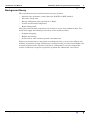
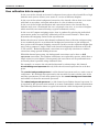
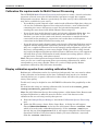
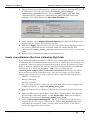
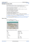
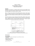
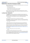
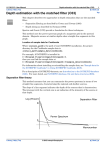
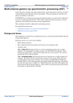
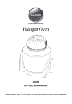
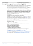
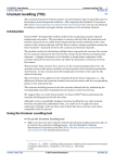
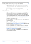
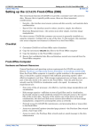
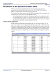
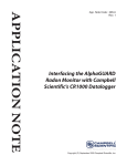
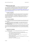
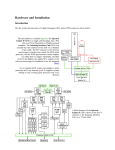
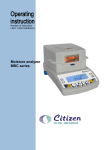
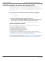
INTREPID User Manual
Library | Help | Top
Calibration gamma ray spectra processing (C07a)
1
| Back |
Top
Calibration gamma ray spectra processing (C07a)
This cookbook provides an introduction to the INTREPID Calibration Spectra
Processing tool. It includes a worked example, which demonstrates how to use the
tool to generate calibration (*.asc) files from calibration flight data. Calibration files
are an essential requirement for running the INTREPID Multi-Channel Radiometric
Processing tool.
The Calibration Spectra Processing tool provides the following main functions:
•
graphically displays cosmic, aircraft and radon spectra from INTREPID
calibration files
•
creates INTREPID calibration files containing cosmic and aircraft spectra from
calibration flight data
It also provides the following Quality Control (QC) functions:
•
reports full width half maximum (FWHM) resolution and spectrometer channel
drift of Radon, K, U and Th photo-peaks from 256-channel survey data
•
detects and reports Null and zero spectra in 256-channel survey data
Location of sample data for Cookbooks
Where install_path is the path of your INTREPID installation, the project
directory for the Cookbooks sample data is
install_path\sample_data\cookbooks.
For example, if INTREPID is installed in
C:\Program Files\Intrepid\Intrepid4.5,
then you can find the sample data at
C:\Program Files\Intrepid\Intrepid4.5\sample_data\cookbooks
For information about installing or reinstalling the sample data, see "Sample data for
the INTREPID Cookbooks" in Using INTREPID Cookbooks (R19).
For a description of INTREPID datasets, see Introduction to the INTREPID database
(G20). For more detail, see INTREPID database, file and data structures (R05).
Library | Help | Top
© 2012 Intrepid Geophysics
| Back |
INTREPID User Manual
Library | Help | Top
Calibration gamma ray spectra processing (C07a)
2
| Back |
Background theory
The correction process for multi-channel spectra includes:
•
Spectral noise reduction, using either the NASVD or MNF method.
•
Live time / Dead time
•
Energy Calibration (also referred to as Drift)
•
Cosmic and Aircraft background
•
Radon background.
After the multi-channel corrections it is normal to create new windowed data. You
would then apply the following corrections to the windowed data:
•
Compton stripping
•
Height attenuation
•
Conversion to radio-element ground concentrations
Before you perform these corrections on radiometric data, you need to calibrate the
airborne acquisition system. Calibration is achieved using a series of test flights and
test pad measurements. The data from these calibrations is used to compute the
various coefficients or spectra required to perform the radiometric corrections.
Library | Help | Top
© 2012 Intrepid Geophysics
| Back |
INTREPID User Manual
Library | Help | Top
Calibration gamma ray spectra processing (C07a)
3
| Back |
How calibration data is acquired
In the case of the aircraft and cosmic background corrections, the aircraft flies a high
altitude stack (series of lines) over water at a series of different heights.
In the case of the radon background correction, the aircraft collects data over water
with little or no radon, and again when there is a lot of radon over water.
In the case of the height attenuation and conversion factors, the aircraft flies an
altitude stack over a nominated line over a dynamic test area, at a series of heights
which would be encountered during a typical radiometric survey.
In the case of Compton stripping ratios, data is gathered by placing the individual
spectometer packs over specially calibrated pads for several minutes. These data
determine the stripping ratios for the spectrometer.
Before the advent of routine 256-channel radiometric data collection and processing,
it was standard practice to perform the background corrections on the windowed
data, prior to the Compton stripping correction. In this case the calibration flight data
was used to compute a single cosmic and aircraft background coefficient each for K,
U, Th and TC. Radon background corrections were typically also done as window
corrections using upward looking detectors.
With 256-channel processing, the background corrections can be done as full
spectrum corrections. The window coefficients are replaced by spectra, which have a
single value for each channel. Consequently the corrections can be performed more
accurately than is possible using windowed data.
For example, we remove the aircraft background by subtracting a 256 channel
aircraft background spectrum directly from the measured spectrum for each data
point.
The cosmic background spectrum is a 256 channel spectrum used as a unit vector of
coefficients. We multiply this spectrum by the measured cosmic window (one of the
ancillary parameters) at each data point to give the cosmic background correction
and subtract it from the measured spectrum.
The radon background spectrum is a 256 channel pure Radon channel spectrum. It
is required by the spectral ratio method, to remove atmospheric radon contamination.
The following illustration shows a typical aircraft and cosmic background spectrum.
Library | Help | Top
© 2012 Intrepid Geophysics
| Back |
INTREPID User Manual
Library | Help | Top
Calibration gamma ray spectra processing (C07a)
4
| Back |
Calibration file requirements for Multi-Channel Processing
The INTREPID Multi-Channel Processing tool requires a cosmic, aircraft and radon
spectrum collected across the full 256 channel spectrum to apply the complete
background corrections. However, particularly for older surveys, this calibration data
may not be available for your survey.
•
If you do have multi-channel cosmic and aircraft calibration flight data, then you
can use the Calibration Spectra Processing tool to derive a new calibration file
containing the correct full-spectra cosmic and aircraft backgrounds, prior to
running the corrections in the Multi-Channel Processing tool.
•
If you do not have multi-channel cosmic and aircraft calibration flight data, but
you do have cosmic and aircraft coefficients for the standard TC, K, U, Th
windows, you can run the cosmic and aircraft corrections as standard window
corrections in the standard_3_corrections tool, rather than as full spectra
corrections in the Multi-Channel Processing tool.
•
If you do not have multi-channel cosmic and aircraft calibration flight data and no
supplied window background coefficients (often the case for older surveys), you
may use a supplied calibration file in the Intrepid config/calibration_spectra subdirectory, corresponding to your survey height. While you will be using aircraft
and cosmic background parameters derived from a different survey, this approach
will still allow you the full benefits of multi-channel processing options, such as
spectral noise cleaning, and radon removal.
Note: The pure radon spectrum changes little from one installation to another. In all
cases you can use a radon spectrum from a pre-existing calibration file, which
corresponds to your survey height. These are a series of high quality Radon
spectrums collected by GA (Geoscience Australia).
Display calibration spectra from existing calibration files
Radiometric calibrations tend to be carried out infrequently, but care must be taken
in the collection and reduction of the data. Calibration data needs to be checked
carefully before use, as poorly collected or reduced data will affect the processed
survey data quality.
To this end, it may be helpful to view INTREPID calibration files graphically on the
screen.
We shall do this using an existing calibration file, located in the install_path/
config/calibration_spectra directory.
Note: For all Calibration Spectra Processing options, a 256-channel Line Dataset and
an Input Calibration (*.asc) file must be chosen, even if the dataset or the
calibration file are not being used by that process.
Library | Help | Top
1
From the Intrepid Project Manager, launch the Calibration Spectra Processing
tool.
2
Under the Files menu, choose Select Input Data. A dialog box will appear.
Choose Select Line Dataset, and select the 256-channel dataset cookrad..DIR,
which is located under cookbooks/radiometrics. If the cookrad..DIR dataset
already has an aliased spectrum field, it will appear alongside the Select Input
Spectrum Field box. If the box remains blank, you must nominate a spectrum
from the cookrad..DIR dataset.
© 2012 Intrepid Geophysics
| Back |
INTREPID User Manual
Library | Help | Top
3
Calibration gamma ray spectra processing (C07a)
5
| Back |
Choose Select Input Calibration File. A chooser will appear, showing the selection
of calibration (*.asc) files from inside the install_path/config/
calibration_spectra directory. Choose cosmic_radon_jwf.asc. This
calibration file was previously compiled for the Multi-Channel Processing
cookbook. Click OK to dismiss the Input Data Selection box.
p
4
Under Options, select Display Calibration Spectra. The data will be displayed as
separate graphs. Choose OK to dismiss the box.
5
Now choose Apply. The tool will pause for a few seconds before drawing graphs of
the various calibration spectra contained within the calibration file. The
calibration file cosmic_radon_jwf.asc contains spectra for cosmic, aircraft and
radon.
6
When you have finished the exercise exit from the tool.
Create new calibration files from calibration flight data
In the following worked example, we will use some actual calibration data to generate
a calibration file. The calibration data was acquired by a helicopter, for the purpose of
generating cosmic and aircraft background correction spectra. It consists of 11 lines,
flown at different altitudes. The data has already been imported into a INTREPID
line dataset. It is called cal_flights..DIR, and can be found in the
install_path\sample_data\cookbooks\radiometrics directory. To achieve
the best results from the calibration data, some pre-processing was done. MultiChannel processing was run on the calibration data, using the following options:
Library | Help | Top
•
NASVD—4 components
•
Energy calibration
•
Livetime correction
•
Save processed spectrum. This is the spectrum that will be used to compute the
background spectra, ie: spectrum_NASVD_Ecal_Live.
1
From the Intrepid Project Manager, launch the Calibration Spectra Processing
tool.
2
Under the Files menu, choose Select Input Data. Click on Select Line Dataset,
and select the calibration dataset, ie: cal_flights..DIR. Make sure the Input
Spectrum field selected is spectrum_NASVD_Ecal_Live.
3
Click on Select Input Calibration File. The file you choose here will serve as a
template for the new output calibration file. Choose dfa_default.asc. This
calibration file contains a cosmic, aircraft and a radon spectra. Click OK to
dismiss the Input Data Selection box.
© 2012 Intrepid Geophysics
| Back |
INTREPID User Manual
Library | Help | Top
Calibration gamma ray spectra processing (C07a)
6
| Back |
4
Under the Files menu, choose Save Output Data. Choose Select Output
Calibration File, and specify a name for the new calibration file, ie:
cal_flights.asc. It will be written to the install_path/config/
calibration_spectra directory.
5
Under the Options menu, select Display Calibration Spectra, and click OK. Then
select Create Calibration Spectra. Both options must be turned on. In the Create
Calibration Spectra box, choose Cosmic and Aircraft Background, and select the
cosmic field from the dataset. Choose OK to dismiss the box.
6
Choose Apply. The tool will pause for a few seconds before calculating spectra
from the calibration dataset, and drawing graphs of the spectra onto the screen.
Notice that for this calibration dataset, the computed aircraft spectrum looks
acceptable, but the computed cosmic spectrum looks flat, and unacceptable. We
can conclude from this that the data cannot be used to provide a useable cosmic
calibration.
7
The spectra will be written to the output file. In this case, the output file will
contain the computed cosmic and aircraft spectra. Because no radon spectrum was
computed, the radon spectrum from the input file will be copied to the output file.
Quality Control Functions
The Calibration Processing tool provides some additional quality control functions for
256-channel survey data.
Spectrometer Drift
Spectrometers are subject to drift, mainly due to temperature and voltage
fluctuations. The drift affects the mapping of the peak energies onto the channel
ranges, and therefore the count rate of the measured photopeaks.
For this example we shall analyse the cookrad..DIR dataset for spectrometer drift.
Library | Help | Top
1
From the Intrepid Project Manager, launch the Calibration Spectra Processing
Tool.
2
Under the Files menu, choose Select Input Data. Select the install_path/
sample_data/cookbooks/radiometrics/cookrad..DIR dataset. Select the
input spectrum field. Choose spectrum, which is the raw spectrum data. This
will be used to compute the drift plots.
3
Click on Select Input Calibration File. Although the tool will not use this file, you
still need to select one. Choose dfa_default.asc. Click OK to dismiss the
Input Data Selection box.
4
Under the Options menu, select Display Calibration Spectra, and click OK. Then
select Quality Control. Both options must be turned on. In the Quality Control
Box, enter low and high channel limits for photo-peaks. These can be found by
using the View function and displaying spectra in the Multi-Channel Processing
tool. Select the Peak Drift (from Energy Calibration) option. Select Energy
Calibrate by Line. Choose OK to dismiss the box.
5
Choose Apply. QC channel drift plots for the Radon, K, U and Th peaks will be
drawn on the screen, along with calibration spectra plots from the specified
calibration file.
© 2012 Intrepid Geophysics
| Back |
INTREPID User Manual
Library | Help | Top
6
Calibration gamma ray spectra processing (C07a)
7
| Back |
Here is an example of a channel drift plot for the Potassium peak. Some peak
drift is evident during the latter part of the survey.
Peak Resolutions
The precision with which a spectrometer can measure gamma ray energies is known
as the system resolution. Resolutions can be calculated for each of the main photopeaks.
Peak resolutions are calculated from the spectrum peaks using the full width half
maximum (FWHM) rule.
Steps 1 to 3 are the same as before:
Library | Help | Top
1
From the Intrepid Project Manager, launch the Calibration Spectra Processing
Tool.
2
Under the Files menu, choose Select Input Data. Select the
install_path\sample_data\cookcooks\radiometrics\cookrad..DIR
dataset. Select the input spectrum field. Choose spectrum, which is the raw
spectrum data. This will be used to compute the peak resolution plots.
3
Click on Select Input Calibration File. Although the tool will not use this file, you
still need to select one. Choose dfa_default.asc. Click OK to dismiss the Input
Data Selection box.
4
Under the Options menu, select Display Calibration Spectra, and click OK. Then
select Quality Control. Both options must be turned on. In the Quality Control
Box, enter low and high channel limits for photo-peaks. These can be found by
using the View function and displaying spectra in the Multi-Channel Processing
tool. Select the Peak Drift (from Energy Calibration) option. Select Energy
Calibrate by Line. Then select Peak Resolution. Choose OK to dismiss the box.
5
Choose Apply. QC resolution plots for the Radon, K, U and Th peaks will be
drawn on the screen, along with calibration spectra plots from the specified
calibration file.
© 2012 Intrepid Geophysics
| Back |
INTREPID User Manual
Library | Help | Top
6
Calibration gamma ray spectra processing (C07a)
8
| Back |
Here is an example of a QC resolution plot for the Potassium peak.
Frequently asked questions
Q : Why do I need to load a dataset and a calibration file if only one is being
used?
A : Future development work on this tool will remove this requirement.
References
Grasty, R.L. and Minty, B.R.S. 1995, A Guide to the Technical Specifications for
Airborne Gamma-Ray Surveys, Australian Geological Survey Organisation, Record
1995/60, Canberra.
IAEA, 1991, Airborne gamma ray spectrometer surveying, Technical Report Series No
323, International Atomic Energy Agency, Vienna.
Library | Help | Top
© 2012 Intrepid Geophysics
| Back |