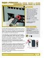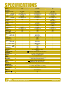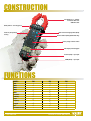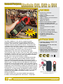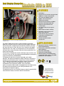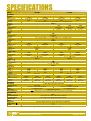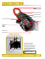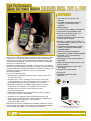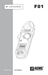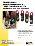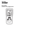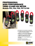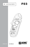
1
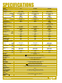
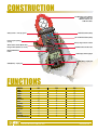
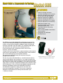
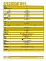
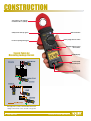
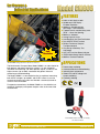
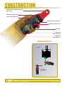
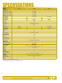
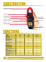
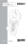
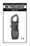
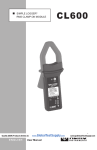
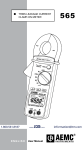
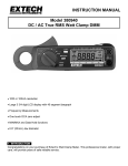
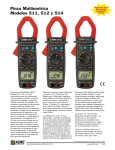
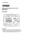
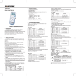
Multi-purpose Clamp-On Meters Rugged Accurate Dependable Affordable Rugged and professional, our complete line of clamp-on meters offer full functions including: Aac, Adc, Vac, Ohms, Continuity, Frequency, Diode Test, TRMS, %THD, %DF, CF and Peak. Varying in size and function, our clamp-on meters provide a solution to all power quality measurement needs. Our products are backed by over 100 years of experience in test and measurement equipment, and encompass the latest international standards for quality and safety. Technical Hotline: (800) 343-1391 www.aemc.com Rugged & Professional Models 500, 502 & 503 FEATURES ►Compact size — fits into your pocket ►400Aac or 400Aac/dc current easurements (model dependent) m ►600Vac/dc volts measurements ►TRMS measurements (Model 502) ►Resistance measurements to 400Ω ►Continuity with beeper below 40Ω ►Frequency measurements (Model 502) from V and A ►Hold function to “freeze” readings ►Push-button for easy Adc zeroing (Model 503) ►Large, easy-to-read 4000-count display ►42-segment analog bargraph ►Supplied with test leads and soft carrying pouch APPLICATIONS Model 502 monitoring phase current on a power panel. The AEMC® Models 500, 502 and 503 are c ompact clamp-on meters that measure up to the toughest professional standards. They are built into a rugged mechanical case and are designed using q uality p olycarbonate materials. These meters offer a complete set of m easurement ranges and are in compliance with international safety and quality standards to ensure a professional and reliable m easuring tool. ►Industrial, commercial, HVAC and r esidential troubleshooting ►Power panel, junction box and battery bank monitoring ►Electrical testing and troubleshooting on traditional and non-linear loads, such as adjustable speed d rives and computers These reliable meters are simple to operate and are Auto-Ranging — always providing the optimum measurement range and resolution. They all measure 400Aac, 600Vac, 600Vdc, Resistance, and Continuity (with beeper). The Model 502 also has a Frequency function sensed from either current or voltage. The Model 503 is average sensing for traditional load environments. The Model 502 is a True RMS clamp-on that provides RMS measurements for today’s non-linear electrical environments, such as variable speed drives or computers. The Model 503 is a Hall Effect clamp-on that provides both DC and AC current m easurements to 400A. The Models 500, 502 and 503 are compact for comfortable one-handed operation. The tapered, hooked jaw design facilitates maneuvering in crowded wiring and breaker panels, making it easy to select conductors. The jaw opening accommodates a 500kcmil cable. The large and easy-toread 4000-count LCD features comprehensive user information s ymbols, such as low battery, p olarity, overload and an analog bargraph for easy trend readings. All models are equipped with a Data Hold function that freezes the measurement for later viewing. Models 500, 502 & 503 are s upplied with a pair of test leads and soft c arrying case They are supplied in a padded carrying pouch with leads, batteries and user manual — ready to go! 2 www.aemc.com Technical Assistance (800) 343-1391 SPECIFICATIONS MODELS ELECTRICAL AC Current (Auto-Ranging) Resolution Accuracy 50 to 60Hz 60 to 500Hz AC Voltage (Auto-Ranging) Resolution Accuracy 50 to 60Hz 60 to 500Hz Input Impedance DC Current (Auto-Ranging) Resolution Accuracy DC Voltage (Auto-Ranging) Resolution Accuracy Input Impedance Resistance-Ohms (Ω) Resolution Accuracy Max Test Voltage Continuity ( ) Max Test Voltage Frequency (Hz) (Auto-Ranging) CURRENT INPUT Range 20Hz to 4kHz >4kHz to 10kHz Accuracy Min Input Signal Input Impedance Overload Protection VOLTAGE INPUT Range 10Hz to 4kHz >4kHz to 40kHz >40kHz to 400kHz Accuracy Min Input Signal 4kHz 40kHz 400kHz Input Impedance Overload Protection Power Source Power-Off Low Power Indication 500 502 TRMS 503 0.05 to 400A 0.1A 2% of Reading ± 5cts 2.8% of Reading ± 5cts 0.5 to 600V 0.1V and 1V 1.0% of Reading ± 5cts 1.5% of Reading ± 5cts 1MΩ – – – – – – – 0.3 to 400Ω 0.1Ω 1.9% of Reading ± 3cts -1.6VDC <35Ω 1.5VDC 0.05 to 400Arms 0.01A and 0.1A 1.9% of Reading ± 5cts 2.5% of Reading ± 5cts 0.5 to 600Vrms 0.1V and 1V 1.5% of Reading ± 5cts 1.5% of Reading ± 5cts 1MΩ – – – 0.2 to 600V 0.1V and 1V 1% of Reading ± 2cts 1MΩ 0.2 to 400Ω 0.1Ω 1% of Reading ± 2cts 1.5VDC <40Ω 1.5VDC 0.05 to 400A 0.01A and 0.1A 1.5% of Reading ± 10cts 2.5% of Reading ± 10cts 0.5 to 600V 0.1V and 1V 0.8% of Reading ± 5cts 1.5% of Reading ± 5cts 10MΩ 0.10 to 400A 0.01A and 0.1A 2.5% of Reading ± 10cts 0.2 to 600V 0.1V and 1V 1% of Reading ± 2cts 10MΩ 0.2 to 400Ω 0.1Ω 1% of Reading ± 2cts 1.5VDC <40Ω 1.5VDC – – – – – – 1Hz Resolution 10Hz Resolution 0.1% of Reading ± 1ct 2Arms 1MΩ 600Arms – – – – – – – – – – – – – – – 1Hz Resolution 10Hz Resolution 100Hz Resolution 0.1% of Reading ± 1ct 5Vrms 5Vrms 5Vrms 1MΩ 600Vrms Two 1.5V AAA batteries (included) 30 minutes Displayed when the battery is below the required voltage – – – – – – – – – MECHANICAL Jaw Opening Size Ø Dimensions Weight 1.1" (28mm) – faciliates 500kcmil cable 7.60 x 1.97 x 1.1" (193 x 50 x 28mm) 8.11 oz (230g) with batteries DISPLAY Digital Display Analog Display Symbol and Scale Range Polarity Overload Sample Rate 3¾ digits LCD display, 4000-count (max. reading 3999) Fast 42-segment analog bargraph display Automatic according to range and input signal Displayed when negative signal applied to input Displayed when input signal exceeds range 2 samples/sec for the digital display, 20 samples/sec for the analog bargraph ENVIRONMENTAL Altitude Operating Temperature Storage Temperature Pollution Degree 2000 m 32˚ to 104˚F (0˚ to 40˚C), <80% RH, non-condensing 14˚ to 140˚F (-10˚ to 60˚C), <70% RH, battery removed 2 SAFETY Safety Rating Double Insulation CE Mark EN 61010, 300V CAT III Yes Yes Technical Assistance (800) 343-1391 www.aemc.com 3 CONSTRUCTION Jaw Opening: 1.1" (28mm) Conductor Size: one 500kcmil cable Safety barrier – anti-slip guard Data hold and ranging b utton (Blue) Lever for jaw opening/ closing DC zero button (Blue) (Model 503 only) Rotary range selector switch LCD display with b argraph Positive (Red) + input jack COM (Black) – input jack Model 503 FUNCTIONS MODELS 500 502 503 TRMS – – 400Aac 400Adc – – 600Vac 600Vdc – Frequency – Bargraph – – Resistance Continuity Beeper Hold Push button DC Zero 4 www.aemc.com – Technical Assistance (800) 343-1391 General Purpose Models 511, 512 & 514 FEATURES ►Standard size, full function clamp-on meters ►1000Aac or 1000Aac/dc current measurements ►750Vac or 1000Vdc volt measurements ►TRMS measurements (Models 512 and 514) ►Resistance measurements to 4000Ω ►Continuity with beeper below 40Ω ►Frequency measurements from V and A ►Diode test ►1ms Peak function for fast capture of signals Fast 1ms Peak capture of inrush current ►Hold function to “freeze” readings ►Push-button for easy Adc zeroing ►Large, easy-to-read 4000-count display ►42-segment analog bargraph ►Supplied with test leads and soft carrying pouch Model 514 measuring primary current on a machine c ontrol system. The AEMC ® Models 511, 512 and 514 are general p urpose clamp-on meters that measure up to the toughest p rofessional standards. They are built into a rugged mechanical case and are designed using quality polycarbonate m aterials. These meters offer a complete set of measurement ranges and are in compliance with international safety and quality standards to ensure professional and reliable measuring tools. The Models 511 and 512 are Auto-Ranging and provide the best m easurement range and resolution for troubleshooting. They also have a high resolution 40A range. They measure AC Amps, AC Volts, as well as DC Volts, Ohms, Continuity (with beeper), Frequency (from V or A) and have a Diode Test function. The Model 514 also uses Hall Effect sensor technology that p rovides both DC and AC c urrent measurements to 1000A. The Models 511, 512 and 514 are sized for comfortable, one-handed operation. The tapered and hooked jaw design facilitates maneuvering in crowded wiring and breaker panels, m aking it easy to select conductors. The jaw opening a ccommodates one 750kcmil cable or two 350kcmil cables. The large and easy-to-read 4000-count LCD features comprehensive user information symbols, such as low b attery, polarity, overload, and an analog bargraph for easy trend readings. All models are equipped with a Data Hold function that freezes the measurement for later viewing, Min/Max, and a fast 1ms Peak Hold function for c apture of signals. The Model 511 is average sensing and designed for traditional a verage responding electrical systems. The Models 512 and 514 are True RMS clamp-ons that provide RMS measurements for today’s non-linear electrical environments. All models include a pair of test leads (red/black with probe tips), 9V battery, soft carrying pouch and a user manual — ready to go! Technical Assistance (800) 343-1391 APPLICATIONS ►Commercial, industrial, residential and HVAC troubleshooting ►Power panel, junction box and battery bank monitoring ►AC or DC motor testing ►Power plant troubleshooting ►Electrical testing and troubleshooting on traditional and non-linear loads, such as adjustable speed drives and computers Models 511, 512 & 514 are supplied with a pair of test leads and soft c arrying case www.aemc.com 5 SPECIFICATIONS MODELS ELECTRICAL AC Current (Auto-Ranging) Resolution Accuracy 50 to 60Hz 60 to 500Hz Overload Protection 40A 400A 1000A AC Voltage (Auto-Ranging) Resolution Accuracy 50 to 500Hz Input Impedance Overload Protection DC Current (Auto-Ranging) Resolution Accuracy Overload Protection DC Voltage (Auto-Ranging) Resolution Accuracy Input Impedance Overload Protection Resistance-Ohms (Ω) Resolution 400Ω 4000Ω Accuracy Max Test Voltage Overload Protection Diode Test Open Circuit Voltage ) Continuity ( Max Test Voltage Frequency (Hz) (Auto-Ranging) CURRENT INPUT Range 4kHz 10kHz Accuracy 20Hz to 10kHz Min Input Signal 4kHz 10kHz VOLTAGE INPUT Range 4kHz 10kHz Accuracy 10Hz to 10kHz Min Input Signal 4kHz 10kHz Power Source Power-Off Low Power Indication 511 512 TRMS 514 TRMS 0.05 to 1000A 0.01A, 0.1A and 1A 1.9% of Reading ± 5cts 1.9% of Reading ± 5cts 800Arms 1500Arms 1500Arms 0.5 to 750V 0.1V and 1V 1.2% of Reading ± 5cts 10MΩ 1000Vrms – – – – 0.2 to 1000V 0.1V and 1V 0.75% of Reading ± 2cts 10MΩ 1200Vrms 0.2 to 4000Ω 0.1Ω 1Ω 1% of Reading ± 2cts 3VDC 600Vrms 0.6mA 3VDC <40Ω 3VDC 0.05 to 1000Arms 0.01A, 0.1A and 1A 1.9% of Reading ± 5cts 1.9% of Reading ± 5cts 800Arms 1500Arms 1500Arms 0.5 to 750Vrms 0.1V and 1V 1.2% of Reading ± 5cts 10MΩ 1000Vrms – – – – 0.2 to 1000V 0.1V and 1V 0.75% of Reading ± 2cts 10MΩ 1200Vrms 0.2 to 4000Ω 0.1Ω 1Ω 1% of Reading ± 2cts 3VDC 600Vrms 0.6mA 3VDC <40Ω 3VDC 0.05 to 1000Arms 0.01A, 0.1A and 1A 1.9% of Reading ± 5cts 2.5% of Reading ± 5cts 1200Arms 1200Arms 1200Arms 0.5 to 750Vrms 0.1V and 1Vrms 1.5% of Reading ± 5cts 10MΩ 1000Vrms 1 to 1000A 0.01A, 0.1A and 1A 2.5% of Reading ± 10cts 1200Arms 0.2 to 1000V 0.1V and 1Vrms 1% of Reading ± 2cts 10MΩ 1000Vrms 0.2 to 4000Ω 0.1Ω 1Ω 1% of Reading ± 2cts 3VDC 600Vrms 1.7mA max 3VDC <40Ω 3VDC 1Hz Resolution – 0.1% of Reading ± 1ct 2Arms – 1Hz Resolution – 0.1% of Reading ± 1ct 2Arms – 1Hz Resolution 10Hz Resolution 0.1% of Reading ± 1ct 2Arms 5Arms 1Hz Resolution 10Hz Resolution 0.1% of Reading ± 1ct 5Vrms 5Vrms 1Hz Resolution 10Hz Resolution 0.1% of Reading ± 1ct 5Vrms 5Vrms 9V Alkaline battery (included) 30 minutes Displayed when the battery is below the required voltage 1Hz Resolution 10Hz Resolution 0.1% of Reading ± 1ct 5Vrms 10Vrms MECHANICAL Jaw Opening Size Ø Dimensions Weight 1.575" (40mm) – faciliates 750kcmil cable or two 500kcmil cables 9.53 x 2.60 x 1.42" (242 x 66 x 36mm) 14.10 oz (400g) with batteries DISPLAY Digital Display Analog Display Symbol and Scale Range Polarity Overload Sample Rate 3¾ digits LCD display, 4000-count (max. reading 3999) Fast 42-segment analog bargraph display Automatic according to range and input signal Displayed when negative signal applied to input Displayed when input signal exceeds range 2 samples/sec for the digital display, 20 samples/sec for the analog bargraph ENVIRONMENTAL Altitude Operating Temperature Storage Temperature Pollution Degree 2000 m 32˚ to 104˚F (0˚ to 40˚C), <80% RH, non-condensing 14˚ to 140˚F (-10˚ to 60˚C), <70% RH, battery removed 2 SAFETY Safety Rating Double Insulation CE Mark 6 www.aemc.com EN 61010, 600V CAT III, EN 61010, 1000V CAT II Yes Yes Technical Assistance (800) 343-1391 CONSTRUCTION Jaw Opening: 1.575" (40mm) Conductor Size: one 750kcmil cable or two 350kcmil cables Safety barrier – anti-slip guard Data hold button (Blue) 1ms Peak hold button (Blue) Lever for jaw opening/ closing Rotary range selector switch C/DC select button (Model 514) A Range button (Models 511 & 512) Relative button and Adc zero Maximum/Minimum button LCD display with b argraph Positive (Red) + input jack COM (Black) – input jack Model 514 FUNCTIONS MODELS TRMS 1000Aac 1000Adc 750Vac 1000Vdc Resistance Diode Continuity Beeper Frequency Bargraph Hold Min/Max 1ms Peak Push button DC Zero 511 512 – – – Technical Assistance (800) 343-1391 – – 514 www.aemc.com 7 Hand-Held & Ergonomic in Design Model 565 FEATURES ►Check for leakage and locate insulation breakdowns on live circuits ►Measures leakage current down to 0.1mA with up to 10µA resolution ►Measures current up to 100Arms ►Measures voltage up to 600VAC/DC ►Measures Hz on either V or A inputs ►Measures Resistance and Continuity ►Hold feature freezes value ►Max feature keeps track of highest measured In-rush value ►Zero button ideal for m easuring relative values ►Filter to isolate 50/60Hz fundamental from harmonics ►Compatible with VDE 0404 ►Backlight display Measuring leakage current on a ground wire with the TRMS Leakage Current Meter Model 565 The TRMS Clamp-on Meter Model 565 is designed to measure low AC currents, which are typically leakage currents in ground conductors. Low currents are measured on the 60mA and 600mA ranges. Note the high sensitivity of the probe: 10μA and 100μA. This is possible through special jaw construction and in particular critical shielding of the jaws. At low measurement levels, shielding out noise is critical for low sensitivity, accuracy and stability. Leakage current may be measured on a ground conductor and through the vector sum on multi-conductors. On a grounded system, clamp around the two or three conducting legs (not the ground conductor). The vector sum of the load currents will cancel out, leaving the leakage current measured. The user may also use the Model 565 as a standard clamp-on meter to measure up to 100Arms, plus standard Vac, Vdc ranges, resistance and continuity with a buzzer. In mAac and Aac, the user can activate a low-pass filter to ignore all currents other than 50/60Hz. In this mode, only the fundamental signal is measured. The difference between the full frequency signal (WIDE displayed on LCD) and Filtered mode (50/60Hz displayed on LCD) essentially corresponds to the current attributable to Harmonics. Model 565 includes two color-coded 5 ft test leads, batteries, soft carrying case and user manual. The Model 565 is ergonomic in design and fits well in the hand. Also, one hand operation is possible. The jaw size is compact yet designed to accommodate most known ground conductors up to 1" (26mm) in diameter. 8 www.aemc.com Technical Assistance (800) 343-1391 SPECIFICATIONS MODEL ELECTRICAL 565 mA AC Current (TRMS, Auto-Ranging) Measurement Range Resolution 60mA 600mA Accuracy 50 to 60Hz 50 to 500Hz 500Hz to 3kHz AC Current (TRMS, Auto-Ranging) Measurement Range Resolution 10A 100A Accuracy 50 to 60Hz 50 to 500Hz 500Hz to 3kHz AC Voltage (TRMS) Measurement Range Resolution Accuracy 50 to 60Hz 50 to 500Hz 500Hz to 3kHz DC Voltage Measurement Range Resolution Accuracy Frequency (Auto-Ranging) Function Resolution 0 to 100Hz 100Hz to 1kHz Sensitivity Accuracy Resistance Measurement Range Resolution Accuracy Continuity Measurement Range Resolution Buzzer Overload Protection Nominal Sample Rate MAX Sample Rate Filter In-Rush Power Source Battery Life Power-Off Low Battery Indication 0 to 600mA 0.01mA (10μA) 0.1mA (100μA) 1.2% of Reading ± 5cts 2.5% of Reading ± 5cts 3.5% of Reading ± 10cts 10 to 100A 0.001A (1mA) 0.01A (10mA) 1.2% of Reading ± 5cts 2.5% of Reading ± 5cts 3.5% of Reading ± 10cts 0 to 600V 0.1V 1.0% of Reading ± 5cts 1.2% of Reading ± 5cts 2.5% of Reading ± 5cts 0 to 600V 0.1V 1.0% of Reading ± 3cts A-Hz 0.1Hz 1Hz 10mArms min 0.5% of Reading ± 2cts V-Hz 0.1Hz 1Hz 5Vrms min 0 to 1kΩ 0.1Ω 1.0% of Reading ± 3cts 0 to 1kΩ 0.1Ω <35Ω ± 25Ω 660Vrms/150Arms – is displayed and buzzer will sound Two measurements per second (approx.) 100ms On (50/60Hz only); Off (Full frequency range) Max 100ms sample time Two 1.5V AAA batteries 45 hrs (approx.) 10 min approx with user override is displayed when battery voltage is low MECHANICAL Dimensions Jaw Opening Size Ø Maximum Conductor Size Weight 8.5 x 2.5 x 1.18" (218 x 64 x 30mm) 1.10" (28mm) 1" (26mm) 10 oz (280g) with batteries DISPLAY Display Type Backlight Four digit LCD LED with 180 sec Auto-Off ENVIRONMENTAL Operating Temperature Storage Temperature 32° to 104°F (0° to 40°C); <80% RH (non-condensing) 14° to 140°F (-10° to 60°C); <70% RH (non-condensing) SAFETY Safety Rating Double Insulation CE Mark EN 61010-1 Ed. 2001, EN 61010-2-032 Ed. 2003, 600V CAT III Yes Yes Technical Assistance (800) 343-1391 www.aemc.com 9 CONSTRUCTION Jaw opening: 1.10" (28mm) Conductor size: 1" (26mm) Data hold button Safety barrier anti-slip guard Lever for opening/closing jaw Rotary range selector switch Backlight, Max hold, and Zero buttons Typical Points for Measuring Leakage Current Backlit display Positive (Red) input terminal jack COM (Black) input terminal jack On single phase systems, the Model 565 will measure leakage current at the source, the load or the ground. 10 www.aemc.com Technical Assistance (800) 343-1391 For Process & Industrial Applications Model CM605 FEATURES ►0.001 to 10A, 10mA to 100A ►10,000-count LCD Display – 1mA Resolution Model CM605 testing automotive electrical connectors The Multifunction Clamp-on Meter Model CM605 is an ideal choice for both process and general industrial markets. It is also the perfect instrument for measuring 4 to 20mA process signals, as well as, the higher currents (up to 100A) associated with general industrial monitoring and troubleshooting. The Model CM605 is a versatile device that is capable of measuring both AC/DC voltages, up to 600V, and AC/DC current. It can also measure resistance up to 10kΩ and includes a continuity buzzer to assist in circuit verification. Excellent Resolution ►100Aac/dc Ammeter with low 10A Range – 1mA Resolution ►Tapered Jaws for crowded wiring areas (Ø.45" – 12mm Jaw Opening) ►600Vac/dc Voltmeter ►Analog Output in Aac/dc ►Auto-Ranging & Adc Zero Push-button ►Data HOLD & PEAK Functions ►Relative Function to Compare Two Measurements ►Ohm Range & Continuity Test with Beeper ►AUTO-OFF and Low Battery Indicator ►IEC/EN 61010 Safety Rated & CE Mark ►600Vrms Overload Protection APPLICATIONS ►Process loop monitoring ►Automotive electrical troubleshooting ►Industrial plant maintenance ►General AC and DC voltage and current monitoring ►Continuity checking For operator convenience, the Model CM605 can also hold the last reading in the display and capture the peak value at the time of the measurement. Model CM605 includes test leads, soft c arrying case and user manual. Technical Assistance (800) 343-1391 www.aemc.com 11 SPECIFICATIONS MODEL ELECTRICAL AC Current Measurement Ranges Accuracy & Resolution Frequency Range DC Current (positive only) Measurement Ranges Accuracy & Resolution AC Volts Measurement Ranges Accuracy & Resolution Frequency Input Impedance DC Volts (positive only) Measurement Ranges Accuracy & Resolution Input Impedance Resistance (Ohms) Measurement Ranges Accuracy & Resolution Test Voltage Continuity Measurement Ranges Resolution Test Voltage Analog Output Output Frequency Output Impedance Other Functions Adc Zero & Relative Function HOLD Function PEAK Function Auto-Ranging Over Range Auto-Off Low Battery CM605 2 Ranges: 10A, 100A 10A: 2.0% of Reading ± 10cts - 1mA Resolution 80A: 2.0% of Reading ± 10cts - 10mA Resolution > 80A: 3.5% of Reading ± 10cts - 10mA Resolution 2 Ranges: 50 to 500Hz 2 Ranges: 10A, 100A 10A: 2.5% of Reading ± 10cts - 1mA Resolution 80A: 2.5% of Reading ± 10cts - 10mA Resolution > 80A: 4.5% of Reading ± 10cts - 10mA Resolution 600Vrms 1.5% of Reading ± 5cts - 100mV Resolution 40 to 500Hz 10MΩ, < 50pF 600V 1.0% of Reading ± 2cts - 100mV Resolution 10MΩ 10kΩ (9999Ω) 1.0% of Reading ± 3cts - 1Ω Resolution < 3.0Vdc Buzzer < 100Ω ± 25Ω 1Ω < 3.0Vdc 10mV/Aac & Adc through front banana jacks 0 to 20kHz @ ± 3db 3kΩ, < 50pF One touch push button (ΔZERO Button) to Zero Adc, or other readings. Relative function also used in the other ranges to compare two measurements. Holds A & V measurements when pressed (HOLD button) Captures PEAK (1ms) V or A measurement when activated (PEAK Button) “AUTO” displayed on LCD “OL” displayed on LCD for all measurements Auto-Off after approx 10 minute with Over-Ride Low Battery indication on LCD MECHANICAL Max. Jaw Opening Size Ø Max. Conductor Size Power Source Dimensions & Weight Ø 0.60" (15mm) Ø 0.45" (12mm) Two 1.5V AAA (LR03) batteries (included) 7.95 x 2.76 x 1.33" (202 x 70 x 34mm) – 6.5 oz (180g) SAFETY Safety Rating Double Insulation CE Mark 12 www.aemc.com IEC/EN 61010-1 and 2-032 – 600V CAT II and 300V CAT III – Pollution Degree 2 Yes Yes Technical Assistance (800) 343-1391 CONSTRUCTION Tapered jaws for crowded wiring or areas (Ø.45"- 12mm) Safety barrier anti-slip guard Lever for jaw opening/closing Data hold and Peak hold buttons Rotary range selector switch LCD display Positive (Red) input terminal jack COM (Black) input terminal jack Measuring AC Current ER N MET 600V CAT II CLAMP-O MODEL ZERO CM605 CAT II 600V Press H 2 Sec P PEA K 100A CORRECT 600V CAT II 100A H Press P PEAK 2 Sec ZERO INCORRECT (two conductors from different phases) MODEL CM605 CLAMP-ON METER 600V CAT II Technical Assistance (800) 343-1391 www.aemc.com 13 Dual Display Clamp-Ons Models 670 & 675 FEATURES ►Dual display ►Standard size, full function clamp-on meter ►1000Aac/dc current measurements (DC Current on Model 675 only) ►1400Vdc volt measurements ►TRMS measurements ►Resistance measurement to 10,000Ω ►Continuity with beeper below 35Ω ►Frequency measurements from V and A inputs ►1ms Peak function for fast capture of signals ►Hold function to “freeze” readings ►Designed to measure Amps and Volts at the same time ►Push-button for easy Adc zeroing ►Large easy-to-read 9999-count backlit LCD display ►Includes test leads and soft carrying case Model 675 measures both volts and amps and displays results simultaneously. The AEMC® Models 670 and 675 are general purpose, dual display, professional clamp-on meters that measure up to the toughest standards. These meters offer a complete set of measurement functions (AC Amps, DC Amps [675 only], AC Volts, DC Volts, Ohms, Continuity with beeper, Frequency from V or A Input, and Temperature) and are in compliance with international safety and quality standards to ensure professional and reliable measuring tools. These meters are designed to measure and display amps and volts at the same time. They are also auto-ranging and provide the best measurement range and resolution for troubleshooting. The Models 670 and 675 are sized for comfortable, one-handed operation. The tapered and hooked jaw design facilitates maneuvering in crowded wiring and breaker panels, making it easy to select conductors. The jaw opening accommodates one 750kcmil cable or two 350kcmil cables. The large and easy-to-read 9999-count LCD features comprehensive user information symbols, such as low battery, polarity and overload. Both models are equipped with a Data Hold function that freezes the measurement for later viewing and Min/Max, and Peak function for capture of signals. The Model 670 and 675 are True RMS clamp-on meters that provide RMS measurements for today’s non-linear electrical environments. 14 www.aemc.com APPLICATIONS ►Commercial, industrial, residential and HVAC troubleshooting ►Power panel, junction box and battery bank monitoring ►AC or DC motor testing ►Power plant troubleshooting ►Electrical testing and troubleshooting on non-linear loads, such as adjustable speed drives and computers SA RA FET Y TIN G The 670 and 675 include meter, set of test leads (red/black with safety needle tips), K-type thermocouple, one 9V battery, soft carrying case and a user manual. Technical Assistance (800) 343-1391 SPECIFICATIONS MODELS ELECTRICAL AC Amperes Range Measuring Range Resolution Accuracy Overload DC Amperes Range Measuring Range Resolution Accuracy Overload AC Volts Range Measuring Range Resolution Accuracy Input Resistance Overload DC Volts Range Measuring Range Resolution Accuracy Input Resistance Overload Resistance-Ohms Range Measuring Range Resolution Accuracy Protection ) Continuity ( Range Beeper Activation Accuracy Protection Frequency (Hz) Function Range Resolution Sensitivity Accuracy Temperature (°C/°F) Range Measurement Range Resolution Accuracy 670 TRMS 100A 0.00 to 99.99A 0.01A 675 TRMS 1000A 100A 100 to 1000A 0.00 to 99.99A 0.1A 0.01A 1.5% ± 5cts (50 to 60Hz), 2.0% ± 5cts (50 to 500Hz), 4.5% ± 5cts (500Hz to 3kHz) 1000Arms 100A 0.00 to 99.99A 0.01A 1.2% ± 5cts – – – – – 1000A 100 to 1000A 0.1A 1000A 100.0 to 999.9A 0.1A 2.5% ± 5cts 1400Adc 1400A 1000 to 1400A 1A 2.5% ± 5cts 1000V 0.0 to 999.9V 0.1V 1.0% ± 5cts (50 to 60Hz), 1.2% ± 5cts (50 to 500Hz), 2.5% ± 5cts (500Hz to 3kHz) 1MΩ 1000Vrms 1000V 0.0 to 999.9V 0.1V 1400V 1000 to 1400V 1V 1% ± 2cts 1MΩ 1400Vdc 1000Ω 10,000Ω 0.0 to 999.9Ω 1000 to 9999Ω 0.1Ω 1Ω 1% ± 3cts, 3.3Vdc (Vmax) 1000Vrms 1000V 0.0 to 999.9V 0.1V 1400V 1000 to 1400V 1V 1% ± 2cts 1MΩ 1400Vdc 1000Ω 10,000Ω 0.0 to 999.9Ω 1000 to 9999Ω 0.1Ω 1Ω 1% ± 3cts, 3.3Vdc (Vmax) 1000Vrms < 35Ω 1% ± 3cts, 3.3Vdc (Vmax) 1000Vrms A - Hz 1000Hz 0.1Hz 3Arms 1000°C -40 to 999.5°C 0.5°C 1.0% ± 2°C V - Hz 10,000Hz 1Hz 5Vrms 1.0% ± 2cts 1200°C 1000 to 1200°C 1°C 1.0% ± 2°C 2192°F -40 to 2192°F 1°F 1.0% ± 4°F A - Hz 1000Hz 0.1Hz 3Arms 1000°C -40 to 999.5°C 0.5°C 1.0% ± 2°C V - Hz 10,000Hz 1Hz 5Vrms 1.0% ± 2cts 1200°C 1000 to 1200°C 1°C 1.0% ± 2°C 2192°F -40 to 2192°F 1°F 1.0% ± 4°F MECHANICAL Digital Display Jaw Opening Size Ø Dimension Weight Power Supply Low Battery Indicator 3 ¾ digits LCD dual display (max reading 9999) 1.65" (42mm) 1.58" (40mm) 10.71 x 3.15 x 1.69" (272 x 80 x 43mm) 10.12 x 3.15 x 1.69" (257 x 80 x 43mm) 17 oz (480g) with battery 15.5 oz (440g) with battery 9V, NEDA 1604 (6F22) Alkaline is displayed when the voltage supplied by the battery is lower than the operating voltage ENVIRONMENTAL Altitude Operating Temperature Storage Temperature Pollution Degree 2000 m * -14° to 122°F (-25° to 50°C) < 80% RH, non-condensing -14° to 140°F (-25° to 60°C) < 80% RH, battery removed 2 SAFETY Safety Rating Double Insulation CE Mark EN 61010-1 Ed.2001; EN 61010-2-032 Ed.2002; 600V CAT IV, 1000V CAT III Yes Yes *Note: If the meter is to be used below 32°F (0°C), we suggest that the battery be replaced to ensure proper results. Technical Assistance (800) 343-1391 www.aemc.com 15 CONSTRUCTION Jaw Assembly Model 670 – 1.65" (42mm) Model 675 – 1.58" (40mm) Safety Barrier Anti-slip Guard Data Hold Button/DC Zero Rotary Range Selector Switch Lever for Jaw Opening/Closing LCD Display Function Buttons: • Display • Min-Max • Backlight COM (black) Input Positive (red) Input AC Voltage and Current Measurement Simultaneously • Clamp the jaws around the conductor to be measured. • Voltage and current measurements will be displayed simultaneously. • If reading is unstable and is hard to read, push the HOLD button and read measurement. WARNING: If overload " " is displayed, unclamp the meter immediately . 16 www.aemc.com WARNING: If overload " " is displayed, unclamp the meter immediately . Technical Assistance (800) 343-1391 High Performance Clamp-On Power Meters Models F05, F07 & F09 FEATURES ►Hand-held size, ultra practical and ergonomic ►True RMS measurement through fast s ampling - accurate on non-linear waveforms ►4kHz Bandwidth ►3.5 Crest Factor @ 600Arms and 900Vrms ►Peak function captures 500µs signals ►Measure Inrush Current on 0.5, 1, 2.5, 5 and 10 cycles (15 to 70Hz) ►Min/Max for automatic capture of extreme values on 100ms samples ►Measure V, A, Ohms, kW, PF, VAR, VA, Hz, Phase Rotation, Temperature, AC + DC (model dependent) ►Temperature measurement up to 1832°F (1000°C) via standard K thermocouple (model dependent) ►Continuity at programmable buzzer threshold from 1 to 400Ω (model dependent) ►Selectable V-Live™ function (buzzer) warns of live circuit The F series is a high performance line of clamp-on meters built into a rugged compact sized case, with exceptional ergonomic design and extraordinary ►Designed for use with variable frequency measurement possibilities. These are definitely not your generic off-the-shelf drives (F05) clamp-on! They are designed to offer professional measurement possibilities ► Battery life displays directly in hours at the rarely seen in a clamp-on meter. push of a button Integrating a fast microprocessor sampling at a high rate, they are completely ► Automatically detects AC or DC and is automatic and perform TRMS measurements on the most distorted waveforms. auto-ranging The Models F05, F07 & F09 offer extraordinary measurement capabilities to the ►Automatic DC current zeroing professional engineers and electricians who rely on professional measurement products. ►Backlit LCD Here are some interesting facts: ►EN 61010-1, EN 61010-2-032, 600V CAT III • Selected models automatically detect AC or DC in Voltage and Current – Just select the function. • All models have a V-Live™ function to warn of the use of live circuits or elevated voltages. They also auto-range for the best resolution on a backlit 4000-count display and have Auto-Off to save the battery. • Models F07 and F09 measure TRMS Voltage and Current and can incorporate the DC component of the signal for the Truest RMS. • All models measure in-rush AC currents from one cycle up to 10 cycles and frequency • Models F05 and F09 measure Phase Rotation (using only two leads!), Power Factor and Power. (up to 240kW) • All models are very ergonomic and can be operated with one hand. • Other features, based on the model, include Temperature, Min/Max/Peak, AC/DC adaptor input enabling the use of accessories (large clamps, light sensors…) Models F05, F07 & F09 are designed for the industrial environment and offer enhanced safety specifications. They conform to the demanding international safety standards with a 600V CAT III rating and are CE marked. Technical Assistance (800) 343-1391 Models F05, F07 and F09 include test leads, soft carrying case and user manual. www.aemc.com 17 SPECIFICATIONS MODELS ELECTRICAL F05 F07 AC Current (Auto-Ranging) 0.2 to 400A AC Voltage (Auto-Ranging) DC Current (Auto-Ranging) 0.2 to 400A DC Voltage (Auto-Ranging) 0.2 to 600V F09 0.2 to 600V AC + DC Current (Auto-Ranging) – 0.2 to 400Arms 0.2 to 400Arms AC + DC Voltage (Auto-Ranging) – 600Vrms 600Vrms Resistance 40kΩ Diode Test Yes Continuity (Beeper) Yes (w/adjustable threshold) Frequency Power (W, VA, VAR) Power Factor Phase Rotation 20kHz 240kW – 5W to 240kW -1.00 to 1.00 – -1.00 to 1.00 – Yes Yes Min/Max/Peak Yes Hold Yes Inrush Current 0.5 to 10 cycles selectable V-Live™ Hazardous Voltage Indicators(1) 45Vp Auto-Off Yes Battery Indicator(2) Yes Buzzer for Overrange Yes Power Source One 9V Alkaline battery (included) MECHANICAL ≤ 1.02" (26mm) Max. Jaw Opening Size Ø Max. Conductor Size Adapter (AC/DC) 500kcmil cable – Dimensions 0 to 4000mV – 2.76 x 7.6 x 1.46" (70 x 193 x 37mm) Weight 9.17 oz (260g) DISPLAY Backlight Yes ENVIRONMENTAL Temperature (int or ext) – -50° to 1832°F (-10° to 1000°C) SAFETY Safety Rating EN 61010-1, EN 61010-2-032, 600V CAT III Double Insulation Yes CE Mark Yes (1) Indicates (2) voltage higher than instrument rating Remaining time expressed in hours on Models F05 and F07 18 www.aemc.com Technical Assistance (800) 343-1391 – CONSTRUCTION Jaw Opening: ≤1.02" (26mm) Conductor Size: one 500kcmil cable Anti-slip guard Rotary function selector Access key for functions outlined in yellow around the selector Jaw opening trigger Hold function + Auto zero DC and lead compensation Backlight function MIN, MAX and PEAK functions Hz button Liquid crystal display Recessed safety input terminals FUNCTIONS MODELS F05 F07 F09 AC, DC AC, DC, AC+DC AC, DC, AC+DC – TRMS Measurement AC/DC Current AC/DC Voltage Power (W, VA, var, PF) Single- and 3-Phase Phase Rotation (W and PF single-phase only) Motor Start-Up (InRush) Temperature Frequency Backlit LCD Display Automatic Switch-Off Display Hold Function Battery Level Indicator Presence of Dangerous Voltage (V-live) Automatic AC/DC Choice of Automatic/Manual Mode Automatic Zero DC Lead Resistance Compensation Min/Max 100ms Peak 500μs – Technical Assistance (800) 343-1391 – www.aemc.com 19 SELECTION CHART MODELS Type AC Current AC Voltage DC Current DC Voltage Resistance (Ω) AC 0.05 to 400A 0.5 to 600V – – 400Ω AC TRMS 0.05 to 400A 0.5 to 600V – 0.2 to 600V 400Ω AC/DC 0.05 to 400A 0.5 to 600V 0.10 to 400A 0.2 to 600V 400Ω AC 0.05 to 1000A 0.5 to 750V – 0.2 to 1000V 4000Ω AC TRMS 0.05 to 1000A 0.5 to 750V – 0.2 to 1000V 4000Ω AC/DC TRMS 0.05 to 1000A 0.5 to 750V 1 to 1000A 0.2 to 1000V 4000Ω AC TRMS 0 to 600mA; 10 to 100A 0 to 600V – 0 to 600V 0 to 1kΩ AC/DC 1mA to 100A 600Vrms 1mA to 100A 600V 0 to 9999Ω AC TRMS 0 to 1000A 0 to 1000V – 1000 to 1400V 1000 to 10,000Ω AC/DC TRMS 0 to 1000A 0 to 1000V 0 to 1400A 0 to 1400V 0 to 9999Ω AC/DC TRMS 0.2 to 400A 0.2 to 600V 0.2 to 400A 0.2 to 600V 40kΩ AC/DC TRMS 0.2 to 400A 0.2 to 600V 0.2 to 400A 0.2 to 600V 40kΩ AC/DC TRMS 0.2 to 400A 0.2 to 600V 0.2 to 400A 0.2 to 600V 40kΩ 500 502 503 511 512 514 565 CM605 670 675 F05 F07 F09 20 www.aemc.com Technical Assistance (800) 343-1391 MODELS Continuity Frequency (Hz) Current Voltage True RMS Jaw Size Dimensions Catalog No. 500 <35Ω – – – 1.1" (28mm) 7.60 x 1.97 x 1.1" 2117.54 <40Ω 20Hz to 10kHz 10Hz to 400kHz 1.1" (28mm) 7.60 x 1.97 x 1.1" 2117.66 <40Ω – – – 1.1" (28mm) 7.60 x 1.97 x 1.1" 2117.22 <40Ω 20Hz to 10kHz 10Hz to 10kHz – 1.58" (40mm) 9.53 x 2.60 x 1.42" 2117.67 <40Ω 20Hz to 10kHz 10Hz to 10kHz 1.58" (40mm) 9.53 x 2.60 x 1.42" 2117.68 <40Ω 20Hz to 10kHz 10Hz to 10kHz 1.58" (40mm) 9.53 x 2.60 x 1.42" 2117.70 0 to 1kΩ 0 to 1kHz 0 to 1kHz 1.1" (28mm) 8.5 x 2.5 x 1.18" 2117.56 Buzzer <100Ω ± 25Ω 50 to 500Hz 40 to 500Hz – 0.60" (Ø 15mm) 7.95 x 2.76 x 1.33" 7000.02 502 503 511 512 514 565 CM605 670 <35Ω 1000Hz 10,000Hz 1.65" (42mm) 10.71 x 3.15 x 1.69" 2117.49 <35Ω 1000Hz 10,000Hz 1.58" (40mm) 10.12 x 3.15 x 1.69" 2117.50 Yes (w/adjustable threshold) 20kHz 20kHz ≤1.02" (26mm) 2.76 x 7.6 x 1.46" 2129.53 Yes (w/adjustable threshold) 20kHz 20kHz ≤1.02" (26mm) 2.76 x 7.6 x 1.46" 2129.54 Yes (w/adjustable threshold) 20kHz 20kHz ≤1.02" (26mm) 2.76 x 7.6 x 1.46" 2129.50 675 F05 F07 F09 Technical Assistance (800) 343-1391 www.aemc.com 21 ORDERING INFORMATION DESCRIPTION CATALOG NO. Clamp-On Meter Model 500 (AC, 400Aac, 600Vac, Ohms, Continuity)................................................................................................................................................................................. Cat. #2117.54 Clamp-On Meter Model 502 (TRMS, 400Aac, 600Vac/dc, Ohms, Continuity)..................................................................................................................................................................... Cat. #2117.66 Clamp-On Meter Model 503 (AC/DC, 400Aac/dc, 600Vac/dc, Ohms, Continuity).............................................................................................................................................................. Cat. #2117.22 Clamp-On Meter Model 511 (AC, 1000Aac, 750Vac/1000Vdc, Ohms, Continuity, Hz).................................................................................................................................................... Cat. #2117.67 Clamp-On Meter Model 512 (TRMS, 1000Aac, 750Vac/1000Vdc, Ohms, Continuity, Hz).............................................................................................................................................. Cat. #2117.68 Clamp-On Meter Model 514 (AC/DC, TRMS, 1000Aac/dc, 750Vac/1000Vdc, Ohms, Continuity, Hz)........................................................................................................................ Cat. #2117.70 Leakage Current Meter Model 565 (TRMS, 10Aac, 100Aac, 600Vac/dc, Hz, Ohms, Contunuity)............................................................................................................................................. Cat. #2117.56 Clamp-On Meter Model CM605 (100Aac/dc, 600Vac/dc, Hz, Ohms, Contunuity)..................................................................................................................................................................... Cat. #7000.02 Clamp-On Meter Model 670 (Dual Display, TRMS, AC Amps, AC/DC Volt s, Ohms, Continuity, Frequency & Temperature)........................................................................... Cat. #2117.49 Clamp-On Meter Model 675 (Dual Display, TRMS, AC/DC Amps & Volts, Ohms, Continuity, Frequency & Temperature)................................................................................. Cat. #2117.50 Clamp-On Meter Model F05 (TRMS, 400Aac/dc, 600ac/dc, Hz, Power (kW), Phase Rotation, Ohms, Continuity).................................................................................................... Cat. #2129.53 Clamp-On Meter Model F07 (TRMS, 400Aac/dc, 600ac/dc, Hz, Ohms, Continuity, Temperature)................................................................................................................................. Cat. #2129.54 Clamp-On Meter Model F09 (TRMS, 400Aac/dc, 600ac/dc, Hz, Power (kW, kVA, kVAR), Phase Rotation, Ohms, Continuity)............................................................................ Cat. #2129.50 22 www.aemc.com Technical Assistance (800) 343-1391 TRAINING SEMINARS AEMC® offers one-day training seminars throughout the USA on Ground Resistance Testing, Insulation Resistance Testing and Power Quality. Public and private c ourses are available. For the schedule of upcoming training seminars contact [email protected], visit our website at www.aemc.com or call (800) 343-1391. Understanding Ground Resistance Testing For field engineers, technicians, utility engineers, supervisors, electricians and inspectors who need or have an interest in testing and certifying electrical power grounding systems. Key topics covered include: • Soil Resistivity • Ground Resistance • 3-Point Measurements • 4-Point Measurements • Clamp-On Measurements • Step and Touch Potential Measurements Understanding Insulation Resistance Testing (Future) For field engineers, technicians, supervisors, electricians, plant maintenance personnel and inspectors who need or have an interest in insulation resistance testing on motors, cables and transformers. Key topics covered include: • Motor Theory • Spot Testing • Timed Tests • Polarization Index • Dielectric Discharge Testing • Temperature correction of test results Understanding Power Quality (Future) For field engineers, technicians, supervisors, electricians, plant maintenance personnel and inspectors who need or have an interest in monitoring, recording and analyzing power quality. Key topics covered include: • Why power quality is important to you • Symptoms and problems associated with poor power quality • Types of disturbances and how to tell them apart • Harmonic analysis - what, why and how to measure • THD - what is it and how much is too much • Power Factor - what is it, why know it and how to measure it Technical Assistance (800) 343-1391 www.aemc.com 23 www.aemc.com AEMC® Website The AEMC® website offers a wide assortment of technical product information, software and firmware updates, user manuals and printable data sheets for all AEMC® products. View AEMC® 's upcoming trade shows and training seminars that take place across the country, read about AEMC® 's NEW products and register purchased AEMC® products. Visit us at www.aemc.com AEMC® Storefront The AEMC® online store offers the opportunity to purchase replacement parts such as fuses, test leads and other accessory items for your test instruments. The online store also offers refurbished and discontinued items at a reduced price. Product specials are also offered. Visit the store at www.aemc.com/store Technical Sales and Assistance If you are experiencing any technical problems, or require any assistance with the proper use or application of any AEMC® instrument, e-mail our technical hotline at [email protected] Call the AEMC® Instruments Technical Assistance Hotline for immediate consultation with an applications engineer: (800) 343-1391 Chauvin Arnoux®, Inc. d.b.a AEMC® Instruments • 200 Foxborough Blvd. • Foxborough, MA 02035 USA • (800) 343-1391 • (508) 698-2115 • Fax (508) 698-2118 Export Department: (978) 526-7667 • Fax (978) 526-7605 • E-mail: [email protected] 950.BR-CLAMPON_0211Rev01 Printed in the USA