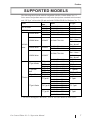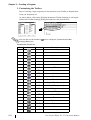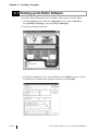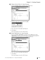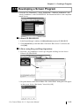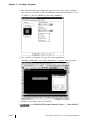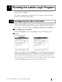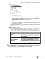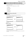
1
PREFACE Thank you for purchasing Pro-face’s ladder logic programing software, ProControl Editor Ver. 5.1. To ensure the safe and correct use of this product, be sure to read all related materials carefully and keep them nearby so that you can refer to them whenever required. NOTICE 1. The copyrights to all programs and manuals included in the Pro-Control Editor Ver. 5.1 software (hereinafter referred to as “this product”) are reserved by Digital Electronics Corporation. Digital Electronics Corporation grants the use of this product to its users as described in the “Software License Agreement” (included with the CD-ROM). Any actions violating the abovementioned conditions are prohibited by both Japanese and foreign regulations. 2. The contents of this manual have been thoroughly inspected. However, if you should find any errors or omissions in this manual, contact your local sales representative. 3. Regardless of the above clause, Digital Electronics Corporation shall not be held responsible for any damages, third-party claims or losses resulting from the use of this product. 4. Differences may exist between the descriptions found in this manual and the actual functioning of this software. Therefore, the latest information on this software is provided in the form of data files (ReadMe.txt files, etc.) and/or separate documents. Refer to these sources as well as this manual prior to use. 5. Even though the information contained in and displayed by this product may be related to intangible or intellectual properties of Digital Electronics Corporation or third parties, Digital Electronics Corporation shall not warrant or grant the use of said properties to any users or other third parties. © 2004 Digital Electronics Corporation. All rights reserved. Digital Electronics Corporation August 2004 For information about the rights to trademarks and trade names, see “TRADEMARK RIGHTS.” Pro-Control Editor Ver. 5.1 Operation Manual 1 Preface TABLE OF CONTENTS PREFACE ...................................................................................................... 1 TRADEMARK RIGHTS ................................................................................7 SUPPORTED MODELS ............................................................................... 7 HOW TO USE THIS MANUAL ....................................................................8 MANUAL SYMBOLS AND TERMINOLOGY.............................................. 9 PRECAUTIONS .......................................................................................... 11 COMPATIBILITY WITH EARLIER VERSIONS ...................................... 13 FOR GLC2400/GLC2600 USERS ........................................................... 14 CHAPTER1 1.1 About Pro-Control Editor ....................................................................... 1–1 CHAPTER2 CREATING A PROGRAM 2.1 Starting up the Editor Software ........................................................... 2–14 2.2 Creating Variables .................................................................................. 2–16 2.3 2.4 2 PRO-CONTROL EDITOR FUNDAMENTALS 2.2.1 Creating a Variable List .............................................................. 2–16 2.2.2 Selecting Variable Types ............................................................ 2–17 2.2.3 Variable List Import/Export ....................................................... 2–18 2.2.4 Saving Your Program ................................................................. 2–24 Inserting Rungs, Instructions, and Branches ..................................... 2–25 2.3.1 Inserting a Rung .......................................................................... 2–25 2.3.2 Deleting a Rung .......................................................................... 2–27 2.3.3 Inserting Instructions .................................................................. 2–28 2.3.4 Deleting Instructions .................................................................. 2–32 2.3.5 Copying and Pasting Instructions .............................................. 2–32 2.3.6 Inserting Branches ...................................................................... 2–33 2.3.7 Initialization Logic ..................................................................... 2–35 Assigning Variables to Instructions ..................................................... 2–37 2.4.1 Instruction Parameter Box .......................................................... 2-37 2.4.2 Entering Variables........................................................................ 2-38 2.4.3 Completing the Program ............................................................. 2-41 Pro-Control Editor Ver. 5.1 Operation Manual Preface 2.5 2.6 2.7 2.8 2.9 Documenting a Ladder Logic Program ............................................... 2–44 2.5.1 Adding a Program Description .................................................. 2–44 2.5.2 Adding a Rung Description........................................................ 2–45 2.5.3 Adding Descriptions to Variables .............................................. 2–46 2.5.4 Description List Dialog Box ...................................................... 2–47 Copying, Cutting, and Pasting Rungs ................................................. 2–48 2.6.1 Copying a Rung .......................................................................... 2–48 2.6.2 Pasting a Rung ............................................................................ 2–48 2.6.3 Cutting a Rung ............................................................................ 2–49 Subroutines and Labels ......................................................................... 2–50 2.7.1 Inserting a Subroutine ................................................................ 2–50 2.7.2 Inserting Labels ........................................................................... 2–53 Navigating a Ladder Logic Program ................................................... 2–54 2.8.1 Using the [Find] Command ....................................................... 2–54 2.8.2 Using the [References] Command ............................................. 2–55 2.8.3 Using the [References] Dialog Box with Other Dialog Boxes 2–57 2.8.4 Using Bookmarks ....................................................................... 2–58 2.8.5 Using the [Go To Rung] Command ........................................... 2–59 2.8.6 Using the [Go To Label] Command .......................................... 2–59 I/O Configuration ................................................................................... 2–60 2.9.1 Assigning Variables to I/O ......................................................... 2–60 2.9.2 Unassigning Variables from the [Configure I/O] Dialog Box . 2–68 2.9.3 Assigning I/O to Variables ......................................................... 2–68 2.9.4 I/O Configuration Import/Export ............................................... 2–69 2.10 Checking the Validity of a Program..................................................... 2–76 2.11 Printing a Ladder Logic Program ........................................................ 2–78 2.12 Importing/Exporting a Logic Program ............................................... 2–80 2.12.1 Export.......................................................................................... 2–80 2.12.2 Import .......................................................................................... 2–82 2.13 Developing a Screen Program ............................................................... 2–85 Pro-Control Editor Ver. 5.1 Operation Manual 3 Preface CHAPTER3 3.1 Configuring the GLC Controller............................................................ 3–1 3.1.1 Writing to the Controller .............................................................. 3–7 3.1.2 Going Online ................................................................................. 3–8 3.2 Starting and Stopping the Controller .................................................... 3–9 3.3 Troubleshooting Using System Variables ............................................ 3–11 3.4 Viewing System Variables ...................................................................... 3–12 3.5 Reading from the Controller ................................................................. 3–13 3.6 Controller Verification ........................................................................... 3–14 3.7 Property .................................................................................................... 3–14 CHAPTER4 ONLINE EDITING 4.1 Before Editing ............................................................................................ 4–1 4.2 Using Colors for Online Editing ............................................................. 4–2 4.3 Turning Discretes ON and OFF .............................................................. 4–3 4.4 Forcing Discretes ON and OFF .............................................................. 4–4 4.5 Changing Variable Values ....................................................................... 4–5 4.6 Changing Variable Attributes ................................................................. 4–6 4.7 Data Watch List......................................................................................... 4–8 4.8 Online Edit (GLC2000 Series Models) .................................................. 4–8 4.8.1 Editing Functions in Online Edit .................................................. 4-9 4.8.2 Saving Data .................................................................................. 4-11 CHAPTER5 5.1 4 RUNNING THE LADDER LOGIC PROGRAM USING THE EDITOR AND GP-PRO/PB III Importing the I/O Symbols to GP-PRO/PB III .................................... 5–1 5.1.1 Starting Up the Editor .................................................................. 5–1 5.1.2 Pasting Instruction Data ............................................................... 5–5 5.1.3 Screen Creation Example – “Pump” Tutorial ........................... 5–12 5.2 Transferring Screens to the GLC ......................................................... 5–14 5.3 Using the “Pump” Project ..................................................................... 5–15 Pro-Control Editor Ver. 5.1 Operation Manual Preface CHAPTER6 PRO-CONTROL EDITOR AND PRO-SERVER 6.1 Importing GLC Variables ............................................................................ 6–1 6.1.1 CHAPTER7 To Import GLC Variables ............................................................. 6–2 ERRORS AND WARNINGS 200-299: Logic Errors and Warnings ............................................................... 7–1 300-399: Variable Errors and Warnings .......................................................... 7–4 400-499: Logic Program Pro-Control Editor I/O Errors and Warnings .... 7–6 500-549: Generic I/O Driver Errors .................................................................. 7–6 600-799: PID Instruction Errors ....................................................................... 7–7 800-899: Specific I/O Driver Errors .................................................................. 7–7 900-1000: Specific I/O Driver Warnings .......................................................... 7–7 CHAPTER8 GLOSSARY APPENDICES APPENDIX 1 Fixed Variable Mode ................................................................... A1 INDEX Pro-Control Editor Ver. 5.1 Operation Manual 5 Preface TRADEMARK RIGHTS The company names and product names used in this manual are the trade names, trademarks (including registered trademarks), and service marks of their respective companies. This product omits individual descriptions of each of these rights. Trademark / Tradename Right Holder Microsoft, MS, MS-DOS, Windows, Windows 95, Windows 98, Windows Me, Microsoft, U.S. Windows NT, Windows 2000, Window XP, Windows Explorer, Microsoft Excel Intel, Pentium Intel, U.S. Digital Electronics Corporation Pro-face, Flex Network (in Japan and other countries) Ethernet Western Digital, U.S. IBM compatible IBM, U.S. Adobe, Acrobat Adobe Systems Incorporated The following terms differ from the abovementioned trade names and trademarks. 6 Term used in this manual Formal Tradename or Trademark Windows 95 Windows 98 MS-DOS Windows NT Windows Me Windows 2000 Windows XP Acrobat Reader Microsoft® Windows® 95 Operating System Microsoft® Windows® 98 Operating System Microsoft® MS-DOS® Operating System Microsoft® Windows NT ® Operating System Microsoft® Windows Me® Operating System Microsoft® Windows 2000® Operating System Microsoft® Windows XP® Operating System Adobe® Acrobat® Reader Pro-Control Editor Ver. 5.1 Operation Manual Preface SUPPORTED MODELS The following table lists the models compatible with Pro-Control Editor Ver. 5.1. Series names and product names are used in the descriptions contained in this manual, and “GP Type” refers to the GP unit used with GP-PRO/PB III for Windows Ver. 7.1. Series GLC100 Series GLC300 Series GLC2300 Series GLC2400 Series GLC2000 GLC2500 Series Series GLC2600 Series LT Type A Series LT Type B/B+ Series LT Type C Series LT Series LT Type H Series Product Name GLC100L GLC100S GLC300T GLC2300L GLC2300T Model GP Type GLC100-LG41-24V GLC100-SC41-24V GLC300-TC41-24V GLC2300-LG41-24V GLC2300-T C41-24V GLC100L GLC100S GLC300T GLC2300L GLC2300 GLC2400*1 “Rev.* - None, 1” GLC2400T GLC2400-T C41-24V GLC2400*1 “Rev.* -Above2” GLC2500-T C41-24V GLC2500 GLC2500T GLC2500 GLC2500-T C41-200V GLC2600*1 “Rev.* - None, 1” GLC2600-T C41-24V GLC2600T GLC2600*1 “Rev.* -Above2” GLC2600-T C41-200V GLC2600 LT Type A1 GLC150-BG41-XY32SK-24V LT TypeA LTC T ype A1 GLC150-SC41-XY32SK-24V LTC T ypeA LT Type A2 GLC150-BG41-XY32SC-24V LT TypeA LT Type B GLC150-BG41-FLEX-24V LT TypeB/B+ LT Type B+ GLC150-BG41-XY32KF-24V LTC T ype B+ GLC150-SC41-XY32KF-24V LTC T ypeB/B+ LT Type C GLC150-BG41-RSFL-24V LT TypeC GLC150-BG41-ADK-24V LT Type H1 GLC150-BG41-ADPK-24V LT TypeH GLC150-BG41-ADTK-24V GLC150-SC41-ADK-24V LTC T ype H1 GLC150-SC41-ADPK-24V LTC T ypeH GLC150-SC41-ADT K-24V GLC150-BG41-ADC-24V LT Type H2 GLC150-BG41-ADPC-24V LT TypeH GLC150-BG41-ADTC-24V 1. For how to distinguish "Revisions", refer to "For GLC2400/GLC2600 Users". Pro-Control Editor Ver. 5.1 Operation Manual 7 Preface HOW TO USE THIS MANUAL The GP-PRO/PB III C-Package03 manuals consist of seven volumes. A description of each is found in the table below. Supplemental explanations and additional or revised information about functions may be provided as data files. To read the data files, click the [Start] button, point to [Programs], [Pro-face], and [ProPB3 C-Package], then click [Read me] to view this information. For detailed information on Pro-face products, please refer to that product’s user manual (sold separately). GP-PRO/PB III C-Package03 Setup Guide Describes software installation and basic application development procedures. Pro-Control Editor Ver. 5.1 User Manual Operation Manual (this manual) Describes the software settings for combining with the GLC, variables, and instructions. Provides exercises for learning the basic functions, from installation to operation, and a list of error messages. Describes procedures using the variables registered by the Pro-Control Editor for use by the GP-PRO/PB III. GP-PRO/PB III for Windows Ver. 7.1 Operation Manual (PDF) T ag Reference Manual Parts List Device/PLC Connection Manual Describes the installation, operating procedures, and software functions of the GP screen creation software. Explains "tags" for specifying on-screen functions of the GP. Describes the parts and symbols provided in the software for creating GP screens. Describes procedures for connecting the GP to PLCs, temperature controllers, and inverters of other manufacturers. For your convenience, after you install the screen editor software, screen layout sheets can be found in the Pro-face folder described below. You can use these layout sheets for specifying the PLC registers when setting the tag addresses. The layout sheets consist of two files: List of Device Assignments and Tag Layout Sheet. The location and name of each file is shown in the following table. For directions on using Microsoft® Excel, refer to the manuals supplied with the software. Folde r Na m e File Na m e De scription List of devic e assignm ents Pro-fac e\propbwin\sheet Devic e1E.xls T AG 1E.xls, T AG 2E.xls, T AG 3E.xls, T AG 4E.xls T ag layout sheet Adobe® Αcrobat® Reader is required to view the CD-ROM’s PDF manuals. * The abovementioned GP-PRO/PB III manuals describe the procedures for developing GP screens. The steps for developing GLC/LT/LT screens are identical; simply substitute “GLC/LT/ LT” for “GP.” * As a supplement to the manuals listed above, detailed explanations are available in the GPPRO/PB III online help. 8 Pro-Control Editor Ver. 5.1 Operation Manual Preface MANUAL SYMBOLS AND TERMINOLOGY This manual uses the following symbols and terminology. If you have any questions about the contents of this manual, please contact your local Pro-face sales distributor. If you have any question about your personal computer or the Windows® software, please contact your local distributor or manufacturer. ! Safety Symbols and Terms This manual uses the following symbols and terms for important information related to the correct and safe operation of this product. Symbol Description Incorrect operation resulting from negligence of this instruction may cause death or serious injury. Incorrect operation resulting from negligence of this instruction may cause personal injury or damage to equipment. Failure to observe this instruction may cause abnormal operation of equipment or data loss. Instructions / procedures that must be performed to ensure correct product use. Actions / procedures that should NOT be performed. ! General Information Symbols and Terms This manual uses the following symbols and terms for general information. Symbol Description Provides hints on correct use or supplementary information. *1, *2, (etc.) Pro-Control Editor Controller GP-PRO/PB III GLC External Communication Device Indicates related information (manual name, page number). Indicates related supplemental information. Referred to in this manual as the "Editor." Software for editing, transferring, and monitoring a GLC/LT unit’s ladder logic program. T he control function of a GLC/LT unit. Screen creation software GP-PRO/PBIII for Windows Ver. 7.1 Indicates the “GLC/LT series” of graphic logic controllers manufactured by the Digital Electronics Corporation. Indicates peripheral devices including PLCs (programmable logic controller), temperature controllers, and inverters. Note that devices connected through Flex Network and DIO are not included. Pro-Control Editor Ver. 5.1 Operation Manual 9 Preface ! Keyboard Compatibility List The following keys may vary, depending on the type of personal computer keyboard you are using. This manual uses the following symbols to indicate a personal computer’s keys: Symbol IBM-Compatible 101-key Keyboard Esc Esc Tab T ab Ctrl Ctrl Shift Shift Alt Alt Delete Delete Back space Backspace ! Typical System Configuration This manual describes this software’s operating procedures and functions based on the typical PC system configuration shown below. If you use a different system configuration from this one, the screen shown on your PC, as well as various item names may be different. In this case, substitute a functionally equivalent item for the one(s) shown here. Item Personal Computer RAM Memory Mouse OS GLC GLC Connection Cable 10 Specification Description Windows-compatible PC with Pentium processor 64 MB Windows-compatible type Windows 98 GLC 2300 Series RS-232C Model code: GPW-CB02 (Digital Electronics Corporation) Pro-Control Editor Ver. 5.1 Operation Manual Preface PRECAUTIONS ! Product Usage Precautions To prevent program malfunctions or accidents, be sure to observe the following: • Example circuits and applications shown in this manual are for reference only. Please be sure that all units and system equipment are operating correctly and safely before using. • Digital Electronics Corporation does not assume the use of this product for applications requiring extremely high degrees of reliability and safety, such as with equipment or systems for transportation, moving, medicine, aerospace, nuclear, or for undersea data communication. Do NOT use this product for these applications. • Touch panel switches should NOT be used for a device’s Emergency Stop Switch. Generally, all industrial machinery/systems must be equipped with a mechanical, manually operated emergency stop switch. Also, for other kinds of systems, similar mechanical switches must be provided to ensure safe operation of those systems. • When there is a risk that a GLC/LT unit problem could cause a serious or fatal accident, or could seriously damage equipment, please install your own backup or failsafe*1 system. • The GLC/LT is NOT designed or manufactured for use in a machine or system that is to be used under circumstances where human life is at risk. Therefore, do NOT use this product for user safety protection or important material-related damage control. • Do NOT turn off your PC’s power switch during the performance of a program. • Do NOT modify the contents of this product’s project files using the text editor feature. • Do NOT transfer screens to the GLC/LT which contain features the GLC/LT series unit does not support. Be sure to use this application only with Administrator level access. Using this application with other access levels may cause an operation error. 1. This type of system minimizes damage caused by operator errors or errors from sensors/ controllers. Pro-Control Editor Ver. 5.1 Operation Manual 11 Preface ! CD-ROM Usage Precautions To prevent CD-ROM damage or CD-ROM drive malfunctions, please observe the following instructions: • Be sure to remove the CD-ROM before turning on and off your PC. • Do NOT remove the CD-ROM disk from the CD-ROM drive while the drive’s operation lamp is lit. • Do NOT touch the CD-ROM disk’s recording surface. • Do NOT place CD-ROMs in an environment where they may be exposed to extreme temperatures, high humidity, or dust. • Do NOT place floppy disks near stereo speakers, TVs, or magnetic therapy equipment. ! Product Restrictions This product has the following restrictions: • GLC100/300 Series/LT Series units do not support Pro-Server with Pro-Studio for Windows (2-Way driver) software. • The GP-PRO/PB III software displays screen data using your personal computer’s fonts and graphic functions. Therefore, there may be a slight difference between data displayed on your personal computer and the same data displayed on the GLC/LT unit. • GP-PRO/PB III functions that cannot be used with GP-370 series units (such as AUX Output, Inching Tags, t-Tag AUX Output, Backup Function) cannot be used with the GLC100. • The device codes and address codes used to specify indirect addresses for GP-PRO/PB III E-tags and K-tags cannot be used with the Pro-Control Editor, since the Editor is not equipped with the variables associated with these device/address codes. • If the GLC/LT unit’s logic time (scan time) becomes too long, the sampling time designated for the trend graph may not be accurately maintained. • Real numbers should be used with the E-tag's and K-tag's “Float” function. However, there may be some errors due to differences between the accuracy of GLC/LT variables (64 bits) and that of tags (32 bits). • GLC/LT variables cannot be used for the trend graph’s Block Indirect Display when M-to-M is selected as the PLC type. • GLC/LT variables are handled using 32 bit-device Low/High order. • With the GLC100, the Q-tag’s Sub Display feature cannot be used. • If a GLC/LT unit’s Logic time (scan time) period is too long, sound file reproduction may be interrupted during playback. 12 Pro-Control Editor Ver. 5.1 Operation Manual Preface • If you are designating a bit using an Integer-type Variable, and a Ttag or a W-tag’s bit (except the “REVERSE” setting) is written to, then all bits will be changed to “0” except for the one that has been designated using an Integer-type variable. • If you are placing multiple T-tags used to reverse a bit’s action (e.g., ON or OFF) on a Base screen, and the same integer variable (e.g., “01”) is used to designate the bit position used by more than one of these T-tags, then only the T-tag placed last (top-most) will be enabled. • All GLC/LT Retentive Variable data is retained by SRAM backup memory that uses a lithium battery. The battery’s backup period lasts approximately 60 days in its initial state (fully charged), and approximately six days when the battery life is almost finished. If you need to back up data for a longer period, you will need to backup data to your host computer. • With the GLC2400, GLC2500 and GLC2600, AUX can only be used for reset input. • Online editing edits the logic program stored in the SRAM. Though all the data in the SRAM may be lost during battery loss at off-state, backup data will be reloaded from the FEPROM. Be sure to “copy to FEPROM (via the OFFLINE menu)” or back up the logic program as a PRW file using Pro-Control Editor. Also, LT Series units cannot perform online editing. • When performing online editing, depending on the type of data transfer packet control used, array variables with large numbers of elements, rungs with either large numbers of variables or large numbers of instructions may not be able to be handled/processed. • Due to differences in PC and GLC/LT Real value accuracy, the values displayed during “Monitoring Mode” may differ. • When the Logic Program and screen data share the same LS area, be sure to designate each Logic Symbol’s LS variable (LS<*>). COMPATIBILITY WITH EARLIER VERSIONS Please read the following precautions if you are currently using versions of ProControl Editor that are earlier than Ver. 3.0. Logic programs are saved in WLL format with Pro-Control Editor versions earlier than 3.0. However, with Ver. 4.0, logic programs are included in the Project Files of the GP-PRO/PB III and saved in PRW format. When using logic programs created with versions earlier than 3.0, you are required to import the WLL files to PRW files. See 2.12 – “Importing/Exporting a Logic Program”. Pro-Control Editor Ver. 5.1 Operation Manual 13 Preface FOR GLC2400/GLC2600 USERS The revision code can be easily found using the GLCunit’s rear face identification label or revision sticker. In the area titled “REV”, the code is indicated by asterisks (*) or marked with a marker pen. ! How to Read the Code In the example below, asterisks (*) are placed at positions “D”, “1”, and “2”, which indicates the revision version as “D-2”. Identification Label Revision Sticker ! Revision Categories Revision Types “Rev.* - None, 1” “Rev.* - Above2” 14 Meaning T he revision code is not used, or is “1”. T he revision code is "2" or higher. Pro-Control Editor Ver. 5.1 Operation Manual 1 Pro-Control Editor Fundamentals 1.1 About Pro-Control Editor Pro-Control Editor Ver.5.1 (hereafter referred to as the “Editor”) is a logic programming software for use with GLC Series units. This Editor contains many features, such as: • GLC DIO unit driver • GLC Flex Network I/F unit driver • LT Type H Series driver • Ladder logic program editor • Ladder logic program transfer feature • Cross-reference reports • Monitoring feature • Online Edit Function*1 • Communication via Ethernet*1 The Editor allows you to develop logic programs compliant with the international standard IEC61131-3 in an easy-to-use Windows environment. Logic programs created with the Editor function on the GLC unit can be used after being downloaded to the GLC. The variables created with the Editor can be transferred to the screen creation software GP-PRO/PB III for Windows Ver. 7.1 and used in conjunction with the display functions (switches and lamps) of the GLC. 1. Supported by GLC2000 Series units only. Pro-Control Editor Ver. 5.1 Operation Manual 1–1 Memo 1–2 Pro-Control Editor Ver. 5.1 Operation Manual 2 Creating a Program This chapter provides step-by-step instructions on using the Editor to create a logic program in Programming mode. For details on starting the Editor, refer to the GP-PRO/PB III Operation Manual, 1.2 – “From Start to Finish”. For a detailed explanation of each part of the Editor, please refer to the Pro-Control Editor User Manual and Online Help. 1. Before Starting the Tutorial Each lesson in this chapter describes how to use the Editor using practice examples, called “tutorials.” This section describes how to use the Editor to create a logic program that controls the operation of soft drink machines used in fast food restaurants. These machines feature the following functions: • Pressing the button once will automatically dispense the required amount of soft drink to a large/medium/small cup. • The ability to dispense ice or soda only if a cup is present under the dispenser. • The ability to count the number of cups filled by the machine since it was turned ON. Examples of Completed Logic Program and Editor Screen The logic program and project file used in this lesson can be found in the “Soda.prw” file, in the “C:\Program Files\Pro-face\ProPBWin\Sample” folder. Refer to this file if you have problems with the tutorials, wish to search for data items, or simply want to study. Refer to the Editor’s Online Help. Logic Program Pro-Control Editor Ver. 5.1 Operation Manual Screen 2–1 Chapter 2 – Creating a Program Soft Drink Machine GLC2300T Unit Light Power OFF button Power ON button Cup Available for Ice (sensor) Hardware Design Flex Network Communication Cable GLC2300T FN-XY16SK Power ON button, Light, etc. Allocating I/O Points The “Ice_pushbutton”, “Large_pushbutton”, “Medium_pushbutton”, and “Small_pushbutton” variables are placed on the GLC screen for touch-panel input and are therefore not allocated to a terminal. 2–2 Variable Name Terminal Type Terminal Number Power_ON_pushbutton Cup_Present_for_Ice Power_Off_pushbutton Light Ice Soda_valve Input Input Input Output Output Output I0 I2 I6 Q0 Q1 Q2 Pro-Control Editor Ver. 5.1 Operation Manual Chapter 2 – Creating a Program 2. Preference Area Settings (Prior to Creating a Logic Program) Prior to creating a logic program using the Editor, you can designate the general settings used in order to customize your program creation/operation. Designating Settings 1. Select [Preferences] from the [File] menu, and the [Preferences] dialog box will appear. Pro-Control Editor Ver. 5.1 Operation Manual 2–3 Chapter 2 – Creating a Program 2. Click each checkbox to select or deselect a setting. The following information explains each tab’s settings. Editor Tab • If selected, the [Instruction Parameter] box is automatically opened for any new instructions inserted in your program. (Default: selected) • If selected, the Editor opens all windows that were open at the end of the last session. Settings (such as window size and position) for any windows open during your editing session are retained. This also applies to the [Data Watch] window which retains its contents when the current program runs online.(Default: selected) • If selected, new instructions are appended to the right of the [focus]. Objects (including rungs, labels, and subroutines) are appended below the [focus]. If cleared, new instructions are inserted to the left of the [focus]. Objects are inserted above the [focus]. If the [focus] is on a [shunt], new instructions are inserted on the [shunt]. (Default: selected) • If selected, the ladder logic screen will be cleared when going to Programming Mode from Monitoring Mode. (Default: not selected) 2–4 Pro-Control Editor Ver. 5.1 Operation Manual Chapter 2 – Creating a Program Monitoring Tab • [power flow] is displayed while the Controller is in RUN mode. The power flow highlights the display of the live (energized) rung (a vertical line used to describe instructions in logic programs) while the Controller is in RUN mode. (Default: clear) Be aware that power flow display updates can be slower than logic execution. • The [state flow] is displayed while the Controller is in RUN mode. The [state flow] highlights the display of the live (energized) instruction while the Controller is in RUN mode. The power flow and State flow can be displayed at the same time. (Default: not selected) • Specifies how often the Editor requests new data from the Controller to update [power flow], [state flow], data values, and the [status bar]. (Default: 500 ms.) Confirmation Tab • If selected, the Editor accepts changes only after the user clicks [Apply]. If enabled (selected), the Editor requires the user’s confirmation. (Default: not selected) • If selected, the Editor asks for confirmation for all deletions when you are creating your program. (Default: selected) • If selected, the Editor asks you to confirm the creation of every new variable in your program. This applies only to the Programming Mode environment. (Default: selected) • If selected, the Editor asks you to confirm any change in the Controller operation (such as Start/ Stop, Read/Write.) (Default: selected) • If selected, the Editor asks you to confirm any undo action. (Default: selected) Pro-Control Editor Ver. 5.1 Operation Manual 2–5 Chapter 2 – Creating a Program FunctionTab • If selected, retentive variable values will be retained when writing to the controller. • When the #Screen feature has been used to change a screen, after the change is completed, the #Screen value will be cleared to “0”. In the logic program or the PLC, when a screen change is performed via the number entered in “#Screen” and “LS[8]” “LS0008”, “PLC’s Allocated Screen Change Number Device”, this feature allows you to check if the screen change has been completed or not. Retain all retentive variables and download (default: disabled) When writing data to the controller, retentive variable values can be retained. Also, when transferring data from GP-PRO/PBIII, this item is enabled. Even though the Check dialog box will not appear, if the variables are not designated as retained, a confirmation dialog box will appear asking if you wish tocontinue with the transfer, or to cancel. Checked (enabled) All retentive variable values are retained. If the Confirmation tab’s [Confirm controller operations] is not selected, no confirmation message dialog box will be displayed. Not checked (disabled) All retentive variable values are initialized (set to “0”) when data is written tothe controller. Change Screen Check (default: enabled) This feature allows you to set whether the completion of a screen change is confirmed, when using the logic program or the PLC’s “#Screen” and “LS[8]” “LS0008”, [PLC’s Allocated Screen Change Number Device] to change screens via a set screen change number. Checked (Enabled) • When using Direct AccessZeroes (“0”) are written to “#Screen” and “LS[8]” “LS0008”, [PLC’s Allocated Screen Change Number Device] after the screen change has been confirmed (via comparing if the System Data Area’s currently displayed screen number is the same as the designated screen change number.). • When using Memory Link A “0” is written after the screen change has been confirmed (via comparing if the System Data Area’s currently displayed screen number is the same as the designated screen change number.). Not Checked (Disabled) • When using Direct AccessAfter the screen change has been confirmed, current screen change values are retained in the “#Screen” and “LS[8]” “LS0008”, “PLC’s Allocated Screen Change Number Device”. • When using Memory Link After the screen change has been confirmed, current screen change value is retained in “#Screen”. 2–6 Pro-Control Editor Ver. 5.1 Operation Manual Chapter 2 – Creating a Program Clipboard Tab • If selected, the fields copied from the variable list of the Editor to the clipboard are separated by commas. E.g., My_variable, Discrete, adescription (Default: not selected) • If selected, the fields copied from the variable list of the Editor to the clipboard are separated by tabs. E.g., My_variable[TAB]Discrete[TAB] adescription (Default: selected) • If selected, the fields copied from the variable list of the Editor to the clipboard are separated by a delimiter and enclosed in double quotes. E.g., “My_variable”, “Discrete”, “adescription” (Default: selected) In this tutorial, be sure to use the default settings. Click [Cancel] to close the [Preferences] dialog box and preserve the default settings. Pro-Control Editor Ver. 5.1 Operation Manual 2–7 Chapter 2 – Creating a Program 3. Customizing the Toolbar Prior to creating a logic program you can customize your Toolbar to display those icons you frequently use. As shown below, click on the [Display/Instruction Toolbar Settings] to call up the [Instruction Toolbar Settings] dialog box and select the desired icons. You can also use the Toolbar’s Settings] dialog box. icon to call up the [Instruction Toolbar Instruction Icon List No. 2–8 Icon Instruc. Description 1 - Insert rung 2 - Insert branch 3 - Label 4 - Sub-routine 5 NO a contact 6 NC b contact 7 OUT OUT coil 8 NEG Reverse coil 9 SET Set coil 10 RST Reset coil 11 PT Positive T ransition contact 12 NT Negative Transition contact 13 AND Bitwise AND (Logical add) 14 OR Bitwise OR (Logical subtraction) 15 XOR Bitwise XOR (exclusive) 16 NOT Bitwise NOT 17 MOV Transfer 18 BMOV Block transfer 19 FMOV File transfer 20 SUM Sum 21 AVE Average Pro-Control Editor Ver. 5.1 Operation Manual Chapter 2 – Creating a Program NO. Icon Instruc. Description 22 BCNT Bit count 23 ROL Rotate left 24 ROR Rotate right 25 SHL Shift left 26 SHR Shift right 27 RCL Left rotation with carry 28 RCR Right rotation with carry 29 SAL Arithmetic shift left 30 SAR Arithmetic shift right 31 ADD Addition 32 SUB Subtraction 33 MUL Multiplication 34 DIV Division 35 MOD Modulus 36 INC Increment 37 DEC Decrement 38 SQRT Square root 39 EQ Equal 40 GT Greater than 41 LT Less than 42 GE Greater than or equal to 43 LE Less than or equal to 44 NE Not equal 45 TON On delay timer 46 TOF Off delay timer 47 TP Pulse timer 48 CTU Count up 49 CTD Count down 50 CTUD Up/down counter 51 BCD BCD conversion 52 BIN Binary conversion 53 ENCO Encode 54 DECO Decode 55 RAD Radian conversion 56 DEC Degree conversion Pro-Control Editor Ver. 5.1 Operation Manual 2–9 Chapter 2 – Creating a Program NO. 2–10 Icon Instruc. Description 57 SCL Scale Conversion 58 JMP Jump 59 JSR Jump subroutine 60 RET Return subroutine 61 FOR FOR 62 NEXT NEXT 63 PID PID calculation 64 SIN sin function 65 COS cos function 66 TAN tan function 67 ASIN Arc sine 68 ACOS Arc cosine 69 ATAN Arc tangent 70 COT Cotangent 71 EXP Exponent 72 LN Natural logarithm Pro-Control Editor Ver. 5.1 Operation Manual Chapter 2 – Creating a Program 4. Aiding Programming with Function Keys When creating a logic program, you can invoke the frequently-used functions such as "Insert Instruction" and "Insert Rung" through short-cut input using the function key. For the functions that can be invoked, refer to the Function Key Assignment List given below. Function Key Assignment List Combination Function key - Ctrl key Shift key F1 Related topic help - - F2 Go to specified rung - - F3 Search next - - F4 Search - - F5 NO (a contact) - NO-OR (a contact OR) F6 NC (b contact) - NC-OR (b contact OR) F7 OUT (OUT coil) F8 F9 F10 Instruction (Insert instruction) Rung (Insert rung) PT-OR (Positive transition contact OR) NT-OR (Negative transition contact OR) Branch (Insert branch) Menu - PT (Positive transition contact) NT (Negative transition contact) - To display function key shortcuts at the bottom of the Editor, go to the [View] menu, select [Toolbar], and click [Function]. Display by key combination When using only the Function key When combining with the Ctrl key When combining with the Shift key Pro-Control Editor Ver. 5.1 Operation Manual 2–11 Chapter 2 – Creating a Program Exercise Overview 1. Start the GP-PRO/PB III C-Package software. See 2.1 – “Starting up the Editor Software”. 2. Select the GLC and external device you will use in the [New] dialog box. See 2.1 – “Starting up the Editor Software”. 3. Develop a logic program. a. Decide on the variables to use. This section describes how to set up operations in Pro-Control Editorcreated logic programs, as well as how to create and delete variables and set the initial values. See 2.2 – “Creating Variables”. b. Create a logic program. This section describes how to create rungs, how to insert instructions and branches, and how to delete rungs, instructions and branches associated with the rungs. See 2.3 – “Inserting Rungs, Instructions, and Branches”. c. Assign variables to a logic program. This section describes how to assign variables to the instructions in a logic program. See 2.4 – “Assigning Variables to Instructions”. d. Insert descriptions. This section describes how to label a logic program with descriptions. The description instructions include procedures for documenting the entire program, specific rungs, and individual instructions. See 2.5 – “Documenting a Ladder Logic Program”. e. Edit. This section describes how to copy, cut, and paste rungs. See 2.6 – “Copying, Cutting, and Pasting Rungs”. f. Subroutine. This section describes how to insert subroutines and labels in a logic program. See 2.7 – “Subroutines and Labels”. 2–12 Pro-Control Editor Ver. 5.1 Operation Manual Chapter 2 – Creating a Program g. Search. This section describes how to quickly search and go to the desired circuit in a logic program. See 2.8 – “Navigating a Ladder Logic Program”. h. Assign I/O. This section describes how to assign the logical variables in a logic program to the actual I/O terminals. See 2.9 – I/O Configuration”. i. Error check. This section describes how to check for errors in a logic program. See 2.10 – “Checking the Validity of a Program”. j. Print. This section describes how to print out a logic program. See 2.11 – “Printing a Ladder Logic Program”. k. Import and export. This section describes how to “read” and “write” a logic program. See 2.12 – “Importing/Exporting a Logic Program”. 4. Develop a screen program. Use GP-PRO/PB III and create a screen linked to a logic program. See 2.13 – “Developing a Screen Program”. Pro-Control Editor Ver. 5.1 Operation Manual 2–13 Chapter 2 – Creating a Program 2.1 Starting up the Editor Software Start up the Project Manager prior to creating a logic program with the Editor. 1. Click the [Start] button, and in the [Programs] menu, point to [Pro-face], then [ProPB3 C-Package], and click [Project Manager]. 2. The Project Manager starts up. 3. In the Project Manager screen, select [New] from the [Project] menu, or click the [New] icon. Designate the settings as follows, and click [OK]. 2–14 Pro-Control Editor Ver. 5.1 Operation Manual Chapter 2 – Creating a Program Description: Soft Drink Server GP Type: GLC series GLC2300 Serial I/F Switch: No PLC Type: DIGITAL Electronics Corp. MEMORY LINK SIO type*1 Extend SIO Type: None 4. A window appears asking whether you will create a Logic Program or a Screen. Click [Edit LogicProgram] to open the Editor. 1. When not connecting the GLC to a PLC or other device, select “Digital Electronics Corp.” and “Memory Link SIO Type” in the “Device/PLC Type” area. Pro-Control Editor Ver. 5.1 Operation Manual 2–15 Chapter 2 – Creating a Program 2.2 Creating Variables This section describes how to designate the functions of the Editor as well as how to create and delete variables and set the initial values used in the Editor. The completed sample of the tutorial program created in this lesson is located in the “Soda.prw” file in the “C:\Program Files\Pro-face\ProPBWin\Sample” folder. Refer to the Pro-Control Editor User Manual, Chapter 2 – “Variables”. Variable Mode and Fixed Variable Mode There are two operation modes available in the Editor to create variables. This tutorial will explain the logic program development in the “Variable Mode”. For details of the fixed variable mode, refer to “Appendix 1 Fixed Variable Mode”. 2.2.1 Creating a Variable List You can add variables at any point while creating a ladder logic program. For convenience, create a list now of the variables you will use in the tutorial. Creating a List Please refer to the online help for detailed descriptions of the menu items. 1. From the [Data] menu, select [Variable List]. The [Variable List] window is displayed. 2. From the [Edit] menu, select [Add Variable]. The [Variable Type] dialog box will appear. 3. Type “Cup_Present_for_Ice” in the Name field and click the [OK] button. For details on variable name restrictions, refer to the Pro-Control Editor User Manual, Chapter 2 – “Variables”. 2–16 Pro-Control Editor Ver. 5.1 Operation Manual Chapter 2 – Creating a Program 2.2.2 Selecting Variable Types The “Cup_Present_for_Ice” variable is now displayed in the [Variable Type] dialog box. The words “Not Assigned” are highlighted in the list below it. There is no variable type assigned to “Cup_Present_for_Ice.” Therefore, it needs to be assigned as a discrete input. Pro-Control Editor User Manual, 2.2 – “Variable Types”. Assigning Variable Types 1. Select [Discrete] from the [Variable Type] list. 2. Select [Input]. 3. Click to deselect the [Retentive] checkbox. Data will not be retained if the power supply is cut, or the GLC unit is reset. 4. Click [Create]. “Cup_Present_for_Ice” has now been assigned as a discrete input. Note that the variable type change that you made to “Cup_Present_for_Ice” in the [Variable Type] dialog box has now taken effect in the [Variable List] window and that the Variable Type dialog box is still open. If you had clicked [OK], the changes would still have occurred in the [Variable List] window, but the [Variable Type] dialog box would have closed. The advantages of leaving these dialog boxes open becomes apparent as you begin inserting rungs and instructions as well as using the Editor’s drag & drop, click, and insert features. You can select the variable types you want to view in the [Variable List] window by selecting [View], then selecting the variable types you want displayed. A check mark appears beside the selected variable types. You have learned how to create a variable and assign a variable type to it. Now create the list of variables shown in the following table. Variables can be created directly in the [Variable Type] dialog box. Variable Name Variable Type I/O Type Retentive Global Power_On_pushbutton Cup_Present_for_Ice Ice_pushbutton Large_pushbutton Medium_pushbutton Small_pushbutton Power_Off_pushbutton Ice Soda_valve Light Fill_Timer Number_of_Larges Number_of_Mediums Number_of_Smalls Discrete Discrete Discrete Discrete Discrete Discrete Discrete Discrete Discrete Discrete Timer Counter Counter Counter Input Input Internal Internal Internal Internal Input Output Output Output Internal Internal Internal Internal Deselect Deselect Deselect Deselect Deselect Deselect Deselect Deselect Deselect Deselect Select Deselect Deselect Deselect Deselect Deselect Select Select Select Select Deselect Deselect Deselect Deselect Deselect Deselect Deselect Deselect Close the [Variable Type] dialog box when you have finished. Pro-Control Editor Ver. 5.1 Operation Manual 2–17 Chapter 2 – Creating a Program If you typed a variable name incorrectly, simply rename it using the [Rename] option in the [Edit] menu in the [Variable List] window. To create variables faster in the [Variable List] window, press the INSERT key. 2.2.3 Variable List Import/Export The variable list can be imported or exported in the CSV file format. To create or edit CSV format variable list data, you can use a standard spreadsheet software like Excel. CSV File Format Selecting the [Variable List] menu’s [File/Export] selection outputs the following Variable List information in CSV file format. Header data // // // // // // ProductName FileVersion ProductVersion CompanyName LegalCopyright CSV FileVersion Pro-Control Editor 5 5.0 Build (24) Digital Electronics Corp. Copyright(C)1 Digital Electronics Corp. 1 @@ GLC @@ 1 2 3 4 5 6 7 8 9 10 11 12 13 14 15 Driver Type Unit Offset 0 0 Name Data Type ID Cup_Present_for_ 1 Fill_Timer 11 Ice 1 Ice_Maker 1 Ice_pushbutton 1 Large_pushbutton 1 Light 1 Medium_pushbutt 1 Number_of_Large 12 12 Number_of_Mediu Number_of_Small 12 Power_Off_pushb 1 Power_On_pushb 1 Small_pushbutton 1 Soda_valve 1 Driver data Variable Set I/O Set 1 0 Data Type Array Size I/O Type ID I/O Type I/O Address I/O Offset Bit 0 Internal 0 Counter 0 Internal 0 Bit 0 Internal 0 Counter 0 Internal 0 Bit 0 Internal 0 Counter 0 Internal 0 Bit 2 Output % QX1.0.2 0 Timer 0 Internal 0 Bit 2 Output % QX1.0.0 0 Bit 0 Internal 0 Bit 1 Input % IX1.0.6 0 Bit 1 Input % IX1.0.0 0 Bit 2 Output % IX1.0.1 0 Bit 1 Input % IX1.0.2 0 Bit 0 Internal 0 Attribute comment G G G R G Variable data Header Data Exported CSV file data will include Pro-Control Editor’s format information (header data). However, when data is imported, this data will not be reflected in the import data’s project file. As a result, you can easily use this control-related data for any use you like. 2–18 ProductName Stores the Project’s name FileVersion Stores the File’s version Pro-Control Editor Ver. 5.1 Operation Manual Chapter 2 – Creating a Program ProductVersion This data should not be modified. CompanyName Stores the company’s name. LegalCopyright Digital Electronics Corporation (Rightholder) CSV FileVersion This data should not be modified. When using a CSV data file to create a new variable list, there is no need to enter anything in the ProductVersion and CSV FileVersion areas. Driver Data (must be entered) This data is about the type of unit connected to the GLC. Driver Type Driver Type data is stored using one of the following ID numbers. If this driver is not used, enter a “0”. Driver Type DIO Driver Flex Network Driver Unit Offset ID No. 0 1 Enter a “0”. Variable Set When the variable names used in the CSV file and the import destination are the same, the following codes are used to designated what processing is performed. Processing Overwrite Add ID No. 0 1 These settings are enabled when the [File -> Preferences -> Confirmation] tab’s [Confirm Controller Operations] check box is not selected. I/O Set When the I/O addresses used in the CSV file and the import destination are the same, the following codes are used to designate what processing is performed. Processing Use a message dialog box to confirm which action to perform. Overwrite Add ID No. 0 1 2 Variable Data (must be entered) This is data for variables allocated to I/O. Name Stores the variable name. For variable name assignment restrictions, Pro-Control Editor User Manual 2.1 Variable Names Pro-Control Editor Ver. 5.1 Operation Manual 2–19 Chapter 2 – Creating a Program Data Type ID Variable types (Discrete, Integers, etc.) are saved using the following ID numbers. For detailed information about variable types, Pro-Control Editor User Manual 2.2Variable Types Variable Type Discrete Integer Real Timer Counter ID No. 1 2 3 11 12 Data Type This comment is related to the Data Type ID. This comment is inserted when a CSV file is exported, however new and other types of files do not need this. Array Size Stores the Array size. For detailed information about arrays, ProControl Editor User Manual 2.3 Accessing Array Variables I/O Type ID I/O types (Input, Output, etc.) are saved using the following ID numbers. I/O Type I/O Type ID No. Internal Input Output 0 1 2 This comment is related to the I/O Type ID. This comment is inserted when a CSV file is exported, however new and other types of files do not need this. I/O Address I/O Addresses are saved using the following format. The characters below that are underlined (“%”, “X” and “1”) are fixed. I/O Address Format: %AB1.C.D A is: Used to store the following I/O terminal ID characters. I/O Terminal ID Character Input T erminal Output Terminal I Q B is: When using a Bit terminal, “X” is stored, and when using a Word terminal, “W” is stored. C is: When using Flex Network units, used to identify/store the unit’s SNo. (Node number) With a DIO Unit driver, this is the module number (0 or 1). With a Uniwire driver, this is the area number (1 to 15). D is: Used to store/identify the terminal number. 2–20 Pro-Control Editor Ver. 5.1 Operation Manual Chapter 2 – Creating a Program I/O Offset Enter a “0” for this setting. Attribute Hold and Global attributes are identified/stored using the following numbers. Comment Variable Attribute ID No. Retained/Global Retained/Local Non-Retained/Global Non-Retained/Local RG R G (Clear) Stores the comment data Export Procedure 1. Select the variables to be exported. 2. Click on the [Variable List] window’s [File/Export] selection. Select the variables to be exported System variables cannot be imported or exported. 3. Designate the location for the CSV to be saved to. Pro-Control Editor Ver. 5.1 Operation Manual 2–21 Chapter 2 – Creating a Program Import Procedure 1. Click on the [Variable List] window’s [File/Import] selection. 2. Designate the CSV file to be imported and click on the [Open] button. 3. If the I/O Addresses have a previously designated address, the following dialog box will appear. Select the method to import the data. 2–22 [Update] Overwrites the current project’s variable data with the imported data. Be sure to use this feature carefully since it will delete all of the current project’s data. [Append] Adds the imported variable data to the end of the existing project’s data. Pro-Control Editor Ver. 5.1 Operation Manual Chapter 2 – Creating a Program 4. If multiple identical variables exist, the following dialog box will appear. If you wish to overwrite the current data with the new data, select [Yes]. If you do not wish to overwrite the current project’s data, select [No]. 5. After the error-check is finished, the import is completed. Do not import an exported I/O configuration’s CSV file to the Variable List. Pro-Control Editor Ver. 5.1 Operation Manual 2–23 Chapter 2 – Creating a Program 2.2.4 Saving Your Program To ensure the safety of created data, it is recommended that you save your logic program periodically. To Save the Program Select [Save] from the [File] menu in the Editor screen. You can also save your program by clicking CTRL + S keys. on the toolbar or by pressing the When a logic program is saved, global variables created with the Editor are automatically registered to the Symbol Editor as GLC symbols, and can be used in conjunction with the display function of GP-PRO/PB III. see GP-PRO/PB III Operation Manual – Screen Creation Guide, 4.7 – “Symbol Editor”. Summary In this section you have learned how to: • create variables and use dialog boxes associated with the variables • determine variable types • Export/Import variable lists • save a program 2–24 Pro-Control Editor Ver. 5.1 Operation Manual Chapter 2 – Creating a Program 2.3 Inserting Rungs, Instructions, and Branches The first step in creating a ladder logic program is to insert a rung. The screen initially shows a blank program as illustrated below. The completed sample of the tutorial program used in this lesson is located in the “Soda.prw” file in the “C:\ProgramFiles\Pro-face\ProPBWin\Sample” folder. 2.3.1 Inserting a Rung Create a new logic program. On the left side of each new program are three rungs labelled START, END, and PEND: • The START rung indicates the start of the main program area. • The END rung indicates the end of the main program area. • The PEND rung indicates the end of the total program area. No rungs can be inserted after the PEND rung. Initial Routines The rungs between START and END are executed every scan. Any rungs inserted before START are initialization logic and are executed on the first scan only. Executed on the first scan only. Subroutine Programs The rungs between END and PEND are reserved for subroutines. For detailed information, “Programmer’s Reference” in the Online Help for a detailed explanation of the START, END, and PEND rungs. Sub-routine program area. Pro-Control Editor Ver. 5.1 Operation Manual 2–25 Chapter 2 – Creating a Program To Insert a Rung 1. Click rung number “1” on the left side of “START”. Rung 1 is selected. 2. Right-click on the rung. The shortcut menu is displayed. 3. Select [Insert Rung]. (Or, select [Rung] from the [Insert] menu.) A new rung is displayed as rung 2 (below rung “START”). 4. Repeat the procedure described above to insert five additional rungs. The screen shown below can be obtained. You can also insert a rung by selecting [Rung] from the [Insert] menu, or by clicking the 2–26 icon in the toolbar. Pro-Control Editor Ver. 5.1 Operation Manual Chapter 2 – Creating a Program 2.3.2 Deleting a Rung To Delete a Rung 1. Select the rung you want to delete. In this example, click rung number “2” on the left side of rung 2. 2. Press the DELETE key, or right-click the rung and click the [Delete Rung] selection. The [Delete] dialog box will appear. 3. Click [OK]. As with other Windows applications, the Editor has an “Undo” command. From the [Edit] menu, select [Undo Changes to XX], or click Pro-Control Editor Ver. 5.1 Operation Manual in the toolbar. 2–27 Chapter 2 – Creating a Program 2.3.3 Inserting Instructions There are many ways to insert instructions into an Editor ladder logic program and assign variables to them. As you create the ladder logic program in the tutorial, these methods are described and used. For details about Instructions, refer to Pro-Control Editor User Manual, Chapter 4 – “Instructions”. Selecting a Rung to Insert Instructions 1. To insert instructions on rung 2, click anywhere on the rung 2 line to select it, but not on the number “2” itself. The selected rung will then be highlighted, as shown below. 2. Once you have selected this rung, you can insert instructions. One way to do this is from the toolbar. The Editor toolbar contains the icons described in the table below.Click these icons to insert instructions into a selected rung. Insert rung Insert branch Label Sub-routine a contact b contact OUT coil On delay timer Off delay timer Count up Count down You can customize toolbar instruction icons by clicking [Display/Instruction Toolbar Settings] or the icon to call up the [Instruction Toolbar Settings] dialog box. See Chapter 2, 3 – “Customizing the Toolbar”. 2–28 Pro-Control Editor Ver. 5.1 Operation Manual Chapter 2 – Creating a Program Method 1: Insert instructions from the toolbar 1. Click the icon. The following box will appear. The instruction now appears on the selected rung. Also, there is a box above it with a flashing cursor inside. This is the “Instruction Parameter Box,” where you enter a variable to associate with the instruction. This will be explained in more detail later in this chapter. icon. This places an output coil on the right side of rung 2. 2. Click the Though the “Instruction Parameter Box” is still flashing, please ignore it for now. For Variable entry information, see 2.4 – “Assigning Variables to Instructions”. 3. Click rung 2, between the NO and OUT instructions. 4. Click the “Normally Closed” (NC) icon , and that symbol will appear. For a description of each toolbar icon’s feature, place the cursor over the icon and read information that appears in the status bar. Though the toolbar offers an easy way to insert frequently used instructions, it does not include all instructions available within Editor. You can also insert instructions using the following two methods. Pro-Control Editor Ver. 5.1 Operation Manual 2–29 Chapter 2 – Creating a Program Method 2: Insert instructions from the [Insert Instruction] dialog box 1. Right-click anywhere on rung 3 and a shortcut menu will appear. 2. Select [Insert Instruction]. The [Insert Instruction] dialog box appears. Instructions belonging to the category selected in the left box are displayed in the right box. For the category that each instruction belongs to, refer to “Pro-Control Editor Users Manual”. You can also create variables in the operand area. Category display Instruction list belonging to a category Opeland area Displays the list of allocatable variables from the Variable List. When checked, System Variables are included in the pull-down list. • You can also bring up the [Insert Instruction] dialog box as well by double clicking a line, by selecting [Instruction] from the [Insert] menu or by pressing the INSERT key after selecting a line. • All instructions have been categorized by items shown in the left box. For details of categories, refer to “Pro-Control Editor Users Manual”. • If you select "all" categories in the left box, all instructions will be listed in the right box. 3. Scroll through the instruction list until “TON” is found. If you select "Timer&Counter" in the left box, TON (Timer On Delay) will appear in the right box. • You can display (or hide) the operand area by clicking the [Operand] button. 2–30 Pro-Control Editor Ver. 5.1 Operation Manual Chapter 2 – Creating a Program 4. Select “TON.” As with the [Variable Type] dialog box, you have a choice of clicking either [OK] or [Apply] to register your selection. Since you are entering other instructions in your ladder logic program in this tutorial, the [Insert Instruction] dialog box needs to remain open. To do this, click [Apply]. 5. Click rung 3, to the left of the TON instruction. 6. Scroll through the list of Editor instructions until you find “NO.” 7. Double-click the “NO” symbol to open it. Method 3: Insert instructions by typing in the [Insert Instruction] dialog box 1. Type “out” in the field above the instruction list. • The instruction list automatically scrolls until the “OUT” instruction appears at the top of the list. Also, its name appears in the bottom-left corner of the dialog box. • You can display (or hide) the operand area by clicking the [Operand] button. 2. Click the rung section to the right of the TON instruction. 3. Click [Apply] and the TON box will appear. Pro-Control Editor Ver. 5.1 Operation Manual 2–31 Chapter 2 – Creating a Program 2.3.4 Deleting Instructions In this section, you will delete the OUT instruction that you just inserted into rung 3. To Delete an Instruction 1. Right-click the OUT instruction on rung 3, and a shortcut menu will appear. 2. Select [Delete]. A dialog box will prompt you to confirm that the instruction is to be deleted. 3. Click [OK]. You can also delete an instruction by selecting it and pressing the DELETE key, or by clicking 2.3.5 in the toolbar. Copying and Pasting Instructions In this section, you will copy the instruction inserted into a rung and paste this instruction into another rung. To Copy an Instruction 1. Click the instruction you wish to copy. 2. Right-click and select [Copy Instruction], or select [Copy] from the [Editor] menu. 2–32 Pro-Control Editor Ver. 5.1 Operation Manual Chapter 2 – Creating a Program To Paste an Instruction 1. Click the location where you wish to insert the copied instruction. 2. Right-click the [Paste Instruction], or click [Paste] from the [Edit] menu. 3. The copied instruction is now pasted (inserted) into the desired rung. 2.3.6 Inserting Branches This section explains how you can insert a branch on rung 2 between the NO and NC instructions. This branch is designed to turn the light in the soda pop machine. To Insert a Branch 1. Place the cursor at the point on the rung where you want the branch to begin. In this case, directly to the left of the NO instruction. 2. Click and drag the cursor pointer to the right. The cursor pointer has turned into a symbol with a dotted line attached to it. Pro-Control Editor Ver. 5.1 Operation Manual 2–33 Chapter 2 – Creating a Program Whenever the end point of the branch is in an incorrect location, the Editor changes your cursor pointer to a symbol. Also, whenever the end point of the branch is in a valid location, the cursor pointer returns to normal. If you release the mouse button while the cursor pointer is normal, a branch is inserted between the starting point and the point where the cursor pointer was when you released the mouse button. If you release the mouse button when the cursor pointer is still a symbol, the branch will NOT be created. 3. Click and drag the cursor pointer to the right, until the cursor pointer is between the NO and NC instructions and is not a symbol. 4. Release the mouse button, and a branch will appear between the NO and NC instructions. To Add an Instruction to a Branch 1. Select the branch by clicking the bottom of it. 2. The [Insert Instruction] dialog box should still be open. If it is not, open it using any of the previously described methods 3. Select the NO instruction from the [Insert Instruction] dialog box and insert it using any of the previously described methods. Rung 2 will appear, as follows: To delete a branch containing instructions, you must first select and delete each instruction. 2–34 Pro-Control Editor Ver. 5.1 Operation Manual Chapter 2 – Creating a Program 2.3.7 Initialization Logic Logic inserted above the START rung is called initialization logic. It is executed only once when the Controller is started. To Insert Initialization Logic 1. Click the “ Program Description” field, located above the START rung. If it is not visible, select [Descriptions] from the [View] menu, and then select [Program]. 2. Select [Insert Rung] from the shortcut menu, and a rung is inserted above the START rung. In the following examples the rungs have been moved down one position (i.e., the rung which was previously number 2 is now rung 3). 3. Right-click the initialization rung (rung1). 4. Select [Insert Instruction] from the shortcut menu. 5. Select the SET instruction from the [Insert Instruction] window and click [OK]. This rung is used to turn the ice machine of a soft drink dispenser ON. It needs to be set only once, and remains ON while the soft drink dispenser’s power is ON. If you do NOT have [Append New Rungs and Instructions] selected in the [Preferences] dialog box, you must select the START rung to insert any initialization rungs. These rungs will appear below the program description. You have now completed rungs 3 and 4 of the ladder logic program, as well as one rung of initialization logic. Please complete rungs 5–7, as shown on the following page. Remember that the |P| instruction is the Positive Transition (PT) instruction. To Insert Multiple Branches into Rung 7 1. Insert the first branch as previously described. 2. Insert the next branch by clicking and dragging from the same point as the previous branch. 3. Drag the cursor around the previous branch to the point on the rung where you want the branch to be inserted. Pro-Control Editor Ver. 5.1 Operation Manual 2–35 Chapter 2 – Creating a Program When the mouse button is released, a new branch will be inserted over the previous branch. In the example below, instructions have been inserted on rungs 5–7. Summary In this section, you have learned how to: • insert and delete rungs • insert and delete instructions • insert and delete branches 2–36 Pro-Control Editor Ver. 5.1 Operation Manual Chapter 2 – Creating a Program 2.4 Assigning Variables to Instructions This exercise shows how to assign variables to instructions. In 2.2 – “Creating Variables,” you created a variable list which includes some of the variables used in the tutorial ladder logic program. Re-open the [Variable List] dialog box to begin this exercise. To Open the Variable List Dialog Box 1. From the [Data] menu, select [Variable List]. 2. Move this dialog box to the lower left corner of your screen. If the [Insert Instruction] dialog box is still open, close it by clicking [Cancel]. 2.4.1 Instruction Parameter Box In the previous section, a field appeared with a flashing cursor inside it when you first inserted an instruction on a rung. This is the “Instruction Parameter Box,” where you enter the variables you want associated with the instruction. To Access the Instruction Parameter Box of a Basic Level Instruction 1. Double-click the OUT instruction on rung 3. A text field will open above the instruction with a flashing cursor inside of it. This is the “Instruction Parameter Box.” The “Instruction Parameter Box” can also be accessed by clicking the instruction and pressing the ENTER key, or by right-clicking the instruction and selecting [Edit Instruction] from the shortcut menu. General instructions (non-basic level instruction) have more than one “Instruction Parameter Box.” For example, a TIMER ON DELAY (TON) instruction has two (2) Instruction Parameter Boxes. One is where you assign a variable, and the other is where you enter the preset time in milliseconds. To Access the Instruction Parameter Boxes of General Instructions 1. Click the TON instruction on rung 4. The TON instruction then changes as follows: Enter the variable name Enter the setting time Above the TON instruction a black highlighted area will appear. This is where you enter the variable to be assigned to the TON instruction. Next to the Preset (PT) element is another black highlighted area. This is where you enter the preset time in milliseconds. Pro-Control Editor Ver. 5.1 Operation Manual 2–37 Chapter 2 – Creating a Program 2. Double-click the black highlighted area above the TON instruction to select the “Instruction Parameter Box.” This is where you can assign a timer variable to the instruction. Enter a variable name here (Instruction Parameter Box) 3. Double-click the area immediately to the left of the PT element in the TON instruction. The [Data Value] dialog box opens. Here, enter the preset time in milliseconds that will elapse before output (Q) is turned ON. (Assigning variables and other operands to instructions will be discussed in the next section.) 4. Close the [Data Value] dialog box. 2.4.2 Entering Variables One method of entering a variable into an Instruction Parameter Box is to type directly into the box. To Enter Text in the Instruction Parameter Box 1. Double-click the OUT instruction’s Instruction Parameter Box on rung 3. 2. Type “Light” in the box. 3. Press the ENTER key. The following dialog box prompts you to confirm the creation of the variable. 4. Click [OK]. In the [Variable List] dialog box, the “Light” variable appears in the list. The Editor has automatically assigned it a variable type. In this case it has assigned it as an internal discrete variable. • The Editor automatically assigns variable types to any new instruction variables created. You can also type a variable that already exists in your variable list directly into an Instruction Parameter Box. The variable is assigned automatically when you finished entering it. • If you set as “Retentive” the variables that have been assigned to “Coil” instructions (i.e., OUT, SET, RST, NEG) , the “Coil” instructions also automatically change to “Retentive” types (i.e., M, SM, RM, NM). 2–38 Pro-Control Editor Ver. 5.1 Operation Manual Chapter 2 – Creating a Program Rung 3 should look like this: Assign the “Ice_Maker” variable to the SET coil on the first initialization rung. This variable can be created by typing it directly into the “Instruction Parameter Box.” After it is typed, the initialization rung appears as follows: Another method of assigning variables to instructions is to simply drag the variable from the [Variable List] dialog box to the instruction itself. This method is very convenient if there are many instructions which need to have the same variables assigned to them. The advantages of using this method are explained in 2.9 – “I/O Configuration.” To Assign a Variable Using the Variable List Dialog Box 1. Call up the [Variable List] dialog box. 2. Click “Light” in the [Variable List] dialog box, but do not release the mouse button. 3. With the mouse button still pressed, drag “Light” to the NO instruction located on the branch on rung 3. As when inserting branches, note that your cursor initially becomes a . When the cursor is in this state you cannot assign the variable to any instruction. When you reach the NO instruction, your cursor will change to a mark. The variable is then assigned when the cursor is released. As long as the cursor appears as a , you can assign the variable to an instruction. Pro-Control Editor Ver. 5.1 Operation Manual 2–39 Chapter 2 – Creating a Program 4. Click and then drag the “Power_On_pushbutton” variable to the other NO instruction on rung 3. Rung 3 should now appear as follows: When you drag the variable over the instruction, the cursor’s symbol changes to an arrow. Dropping the variable will map the variable to the instruction. Constants can be mapped as variables. The input method is the same as that used for normal variables. However, constants must be typed, since there is no window to drag them from. 2–40 Pro-Control Editor Ver. 5.1 Operation Manual Chapter 2 – Creating a Program 2.4.3 Completing the Program Since you have learned how to assign variables to instructions, you can now complete the remaining rungs of the program. A diagram of the completed rungs follows this section (see following page). Notice that the MOV instruction on rung 6 and the NC instruction on rung 7 contain the variables “Fill_Timer.PT” and “Fill_Timer.Q” respectively. These variables refer to the “PT” and “Q” elements of the Timer with the “Fill_Timer” variable assigned to it. The following three procedures are available for entering these variables. • Select the Instruction Parameter Box and type the “Fill_Timer” variable in directly. • Click and drag the “Fill_Timer” variable from the [Variable List] dialog box, and add the “.PT” and “.Q” extensions in the Instruction Parameter Box. • Drag the Instruction Parameter Box to the instruction you want to copy, and enter a variable selected from the special Variable List. The following are detailed instructions for this procedure. 1. Select the source Instruction Parameter Box you want to copy from. 2. Drag the counter and timer variables to the destination instruction you want to copy. 3. Select and double-click the desired parameter from the special Variable List Box. These methods are used with rungs 6 and up. The application instructions’ exclusive variables, such as “Fill_Timer.PT” or ”Fill_Timer.Q,” consist of a variable name and a file extension, as follows: ***.CV (Current value) ***.PT (Set value) ***.Q (Output bit) ***.R (Reset bit) see Pro-Control Editor User Manual, 2.2 – “Variable Types”. Pro-Control Editor Ver. 5.1 Operation Manual 2–41 Chapter 2 – Creating a Program Tutorial Program (Sample) The following logic program was created from the previous tutorial exercises. Summary In this section, you have learned how to assign variables to instructions. 2–42 Pro-Control Editor Ver. 5.1 Operation Manual Chapter 2 – Creating a Program [Hidden part of logic program] When the rightmost part of the rung line cannot be displayed within the screen because the line becomes excessively long, it can be continued on the following line so that the program can be displayed within the screen. Click on [View/Line Turn Back]. The rung line is continued on the following line so that the program can be displayed within the screen and printed. No instruction or branch can be inserted in the middle of a turned-back rung line (that continues on the following line) or vertical line. Also when printing the logic program, the rung line is continued on the following line so that the program can be printed within the paper. Pro-Control Editor Ver. 5.1 Operation Manual 2–43 Chapter 2 – Creating a Program 2.5 Documenting a Ladder Logic Program In the Editor, you can add a description to a program (how it performs), to a rung (how it operates), and to a variable (how it is used). These descriptions explain to users exactly how the program and each of its elements perform, and are useful when the program needs altering or if it needs debugging. 2.5.1 Adding a Program Description The first description to add to your ladder logic program is a description explaining the program’s features. To Add a Program Description 1. Double-click the “Program Description” field at the top of the screen, and the [Description] dialog box will appear. Message Field Text Field All Editor descriptions are entered here. The word “Program” above the text field in the Description dialog box indicates that the text field contains a description of the program. 2. Click the “Program Description” text. 3. Type “This program runs a typical fast food restaurant soft drink dispensing machine.” 4. Click [OK]. This description now appears at the very top of the ladder logic program. (You may need to scroll up to see it.) You can also add or edit a Program Description by double-clicking the bottom-left panel of the status bar. 2–44 Pro-Control Editor Ver. 5.1 Operation Manual Chapter 2 – Creating a Program 2.5.2 Adding a Rung Description In the Editor, you can add descriptions to each rung of your program. In the following example, a description is added to rung 5. To Add a Rung Description 1. Right-click the number to the left of rung 5. 2. Select [Description] from the shortcut menu, and the [Description] dialog box (that you opened previously) opens. However, the descriptor above the text field now says Rung 5 instead of Program. You can also open the [Description] dialog box by selecting [Description] from the [Edit] menu or by clicking in the toolbar. Rung 5 controls the ice dispenser. 3. Click the text field of the [Description] dialog box. 4. Type “Ice is dispensed for as long as the pushbutton is pressed, providing a cup is present.” 5. Click [Apply]. To add descriptions to the remaining rungs of your program easily, keep the [Description] dialog box open. To Add a Description to Rung 3 1. Click anywhere on rung 3, outside of the Instruction Parameter Boxes. The descriptor at the top of the [Description] dialog box now says Rung 3. 2. Click the text field. 3. Type “The Light remains on until the Power_Off_Pushbutton is pressed.” 4. Click [Apply]. In this tutorial only the comments for rungs 3 and 5 are explained. Pro-Control Editor Ver. 5.1 Operation Manual 2–45 Chapter 2 – Creating a Program 2.5.3 Adding Descriptions to Variables Descriptions can also be added to each of the variables in your ladder logic program. You cannot however, add descriptions to labels or constants. To Add a Description to a Variable 1. The [Variable List] dialog box should be open. If it is not, open it by selecting [Variable List] from the [Data] menu. 2. The [Description] dialog box should also be open. If it is not, open it by selecting [Description] from the [Edit] menu. 3. Click any Instruction Parameter Box containing the “Fill_Timer” variable . Note that not only does the [Description] dialog box contain the descriptor “Fill_Timer”, but that “Fill_Timer” is also highlighted in the [Variable List] dialog box. 4. Click the text field of the [Description] dialog box. 5. Type “The Fill Timer decides how long to keep the soda valve open. The operating time depends on the set value.” 6. Click [Apply]. You can also add descriptions to a variable by selecting the variable in the [Variable List] dialog box, instead of selecting it from the ladder logic program. To Add a Description You will now add a description to the “Power_On_pushbutton” variable. 1. Click the “Power_On_pushbutton” variable in the [Variable List] dialog box. The [Description] dialog box now contains the descriptor “Power_On_pushbutton.” 2. Click the text field of the [Description] dialog box. 3. Type “The Power On pushbutton starts the soft drink machine.” 4. Click [Apply]. In this tutorial, descriptions are added to only the “Fill_Timer” variable and the “Power_On_Pushbutton” variable. Descriptions for other variables can be created by simply repeating the procedure described here. 2–46 Pro-Control Editor Ver. 5.1 Operation Manual Chapter 2 – Creating a Program 2.5.4 Description List Dialog Box The [Description List] dialog box displays brief, one line descriptions of all variables and rungs in the program. To Bring up the Description List Dialog Box • From the [View] menu, select [Description List]. To View a Detailed Description from the Description List Dialog Box Double-click the “Fill_Timer” variable in the [Description List] dialog box. The [Description] dialog box displays a detailed description of the “Fill_Timer” variable. The [Variable List], [Description], and [Description List] dialog boxes display changes to the selected rungs and variables in the ladder logic program. However, the opposite is not possible. For example, if a variable in the [Variable List] dialog box or a description from either the [Description] or [Description List] dialog box is selected, the corresponding choice will not be reflected in the ladder logic. The Search function of the Editor allows you to find the specific variables easily. This will be explained in more detail in 2.8 – “Navigating a Ladder Logic Program.” Summary You have learned how to add descriptions to the program, to rungs, and to variables, as well as how to call up the [Description List] dialog box. Pro-Control Editor Ver. 5.1 Operation Manual 2–47 Chapter 2 – Creating a Program 2.6 Copying, Cutting, and Pasting Rungs When creating a ladder logic program, you may find you have to duplicate sequences of instructions on several rungs. You can save time by copying and pasting completed rungs. 2.6.1 Copying a Rung In the following exercise, two rungs are added between rungs 5 and 7. These additional rungs contain the same instructions as rung 6, with different variables assigned to them. To Copy a Rung 1. Click the number “6” to the left of rung 6, to select the entire rung. 2. From the [Edit] menu, select [Copy]. If you wish to select a range of rungs to be cut or copied, click the number of the first rung you wish to select. Hold the [SHIFT] key down, then select the number of the last rung you wish to select. All rungs between and including the two are selected and can be cut or copied. Copying is limited to approximately 25 rungs. 2.6.2 Pasting a Rung The Editor pastes rung(s) below the current rung, except when all the rungs are selected. If [Append new rungs and instructions] is not selected in the [Preferences] dialog box, the copied rung is inserted above the current rung. A cut-and-pasted rung is loaded to the internal clipboard, then copied to the program. If you select an entire rung when pasting from the clipboard, the Editor replaces the rung you have selected with the rung in your clipboard. To Paste a Rung 1. Click anywhere on rung 6. 2. From the [Edit] menu, select [Paste]. Rungs 6 and 7 are now identical. 3. Click anywhere on rung 6. 4. From the [Edit] menu, select [Paste]. Rungs 6 to 8 are now identical. 2–48 Pro-Control Editor Ver. 5.1 Operation Manual Chapter 2 – Creating a Program When pasting a rung, all variables and descriptions associated with that rung are also pasted. Be aware that you may have to edit the pasted rung. The variables on rungs 7 and 8 should now be changed, according to the following example. 5. Change the variable name of the PT instruction on the rung, as shown in the example above. 2.6.3 Cutting a Rung The Editor’s Cut command allows you to take either a rung or a section of rungs out of one part of your program and move them to another. In the following tutorial, rung 4 is to be moved to the last rung of your program. To Cut a Rung 1. Click rung 4. The entire rung is selected. 2. From the [Edit] menu, select [Cut]. The rung is now taken from the ladder logic program and placed on the clipboard. 3. Click anywhere on rung 8. 4. From the [Edit] menu, select [Paste]. Rung 4 is now appended below rung 8. The end of the program now appears as follows: To move an entire rung to another part of the program, select the rung and drag it, using the middle of the rung, to the new location. Summary In this section, you learned how to copy, cut, and paste rungs. Pro-Control Editor Ver. 5.1 Operation Manual 2–49 Chapter 2 – Creating a Program 2.7 Subroutines and Labels When a [JSR] (jump to subroutine) or [JMP] (jump) instruction is inserted in a rung, it tells the Controller to resume scanning, starting from that subroutine or label. The main difference between a subroutine and a label is that the Editor executes a subroutine and then returns to the point in the ladder logic, directly after the [JSR] instruction. If the Editor jumps to a label (via the [JMP] instruction), it will continue to execute the ladder logic program at that point, and will not return to the [JMP] instruction during that scan. For more information on the [JMP] and [JSR] instructions, see the ProControl Editor User Manual, 4.2.53 – “JMP (jump)” and 4.2.54 – “JSR (jump to subroutine)”. 2.7.1 Inserting a Subroutine At the bottom of every logic program are two rungs labelled “END” and “PEND.” The “END” label signifies the end of the main program area. The Editor executes the instructions between “START” and “END” with every scan. The area between the “END” label and the “PEND” (Program End) label is reserved for subroutines. In the following tutorial, a subroutine is added. To Insert a Subroutine 1. Click the [END] label. 2. From the [Insert] menu, select [Subroutine]. The [Insert Subroutine] dialog box appears. 3. Type ”Reset_Counters” in the [Name] field of the [Insert Subroutine] dialog box. A maximum of 32 text characters, numbers, or underscore characters can be used for a subroutine name. Variable names cannot begin with numerical characters and cannot contain spaces. See 2.2.1 – “Creating a Variable List”. 2–50 Pro-Control Editor Ver. 5.1 Operation Manual Chapter 2 – Creating a Program 4. Click [OK]. The subroutine appears between “END” and “PEND,” with two new rungs labelled “SUBSTARTReset_Counters” and “SUBENDReset_Counters.” Now insert another subroutine between the two new rungs. 5. Right-click the “SUBSTARTReset_Counters” label. 6. Select [Insert Rung] from the shortcut menu to insert a rung between the “SUBSTART” and “SUBEND” rungs. 7. Right-click the rung between “SUBSTART” and “SUBEND.” 8. Insert an “OUT” instruction in the rung. 9. Insert two (2) branches around the “OUT” instruction. 10. Insert an “OUT” instruction on each branch. The following is the completed subroutine. This routine will reset each of the Counters every time the GLC is turned ON. Each of the variables you see here should be assigned to each of the “OUT” instructions. Assign these variables now to completes the subroutine. Pro-Control Editor Ver. 5.1 Operation Manual 2–51 Chapter 2 – Creating a Program You can add more than one subroutine to a ladder logic program by selecting either the “SUBSTART” or “PEND” rungs and repeating steps 2 through 6. If you want a subroutine to be executed at some point in your ladder logic program, you must insert a [JSR] instruction. This is explained in the following tutorial. This subroutine is executed as soon as the ‘Light’ OUTPUT COIL on rung 3 turns ON. Therefore, the [JSR] instruction must be placed on rung 4. To Insert a [JSR] Instruction 1. Select rung 3. 2. From the [Insert] menu, select [Rung]. 3. Insert a [PT] instruction on rung 4. 4. Assign the ‘Light’ variable to the [PT] instruction. 5. Insert a [JSR] instruction to the right of the [PT] instruction. This is done from the [Insert Instruction] dialog box. 6. Type ‘Reset_Counters,’ the name of the subroutine, in the [Instruction Parameter Box] of the [JSR] instruction. The rung appears as follows: Whenever the [JSR] instruction “Reset_Counters” receives power, it will jump to the “Reset_Counters” subroutine. Execution will resume from rung 5 once the subroutine has finished execution. To delete a subroutine, you must first delete the individual rungs. After that, delete the “SUB START” rung. The “SUB END” rung will then be automatically deleted when the “SUB START” rung is deleted. 2–52 Pro-Control Editor Ver. 5.1 Operation Manual Chapter 2 – Creating a Program 2.7.2 Inserting Labels A label, which is combined with a [JMP] (Jump) instruction, can be inserted in any part of a ladder logic program. When the Controller executes a [JMP] instruction, it jumps to the designated label and begins to execute the program from that point. Labels are inserted above or below the selected rung if [Append new rungs and instructions] has been selected in the [Preference] dialog box. This tutorial does not use any labels. However, to insert a label, the following procedure is used. To Assign a Label to a Ladder Logic Program 1. Click anywhere on the rung. 2. From the [Insert] menu, select [Label]. The [Insert Label] dialog box prompts you to insert a name for your label. This is the name that is designated in the [JMP] instruction in your ladder logic program. The same rules that apply to the naming of variables also apply to the naming of labels. To Insert a [JMP] Instruction 1. Right-click to the right of the last instruction on the rung, and select [Insert Instruction] from the shortcut menu. 2. Double-click the [JMP] instruction in the [Insert Instruction] dialog box. The [JMP] instruction is inserted as the last instruction on the rung. Whenever the Editor sees this instruction in your program, it jumps to the designated label. Summary This section explained how to create subroutines and labels, and how to insert [JMP] (jump) and [JSR] (jump to subroutine) instructions. Pro-Control Editor Ver. 5.1 Operation Manual 2–53 Chapter 2 – Creating a Program 2.8 Navigating a Ladder Logic Program If a logic program is large, using the scroll bars to locate specific points in the program can take quite a bit of time. The Editor features commands to help you find specific points in your program more quickly. These commands are [Find], [References], [Bookmark], [Go to Rung] and [Go to Label]. 2.8.1 Using the [Find] Command The [Find] command allows you to locate specific textual references in your ladder logic. To Use the Find Command 1. If you have any windows open, close them before you use the [Find] command. 2. From the [Search] menu, select [Find]. The [Find Text] dialog box appears: The [Find Text] dialog box can also be opened by clicking in the tool bar. Specifying the type of match to apply to the search • You can specify the type of match to apply to the search. If you try to find the word ‘Fill,’ the Editor will find all instances of that word, even if it is found as a lower case ‘fill’ or as part of another word, such as ‘Fillet.’ • If you select [Case sensitive], the Editor will find ‘Fill’ but not ‘fill.’ If you select [Whole words only], the Editor will find ‘Fill’ but not ‘Fillet.’ 2–54 Pro-Control Editor Ver. 5.1 Operation Manual Chapter 2 – Creating a Program Specifying the scope and direction of the search • You can specify the scope and direction of the search. If [Selection only] is selected, the scope is limited to the highlighted portion of your program. • Selecting [Global] includes the entire program. You can begin the search from the top of the selected scope by selecting [Entire scope], or from a given position by selecting [From cursor]. This tutorial starts the search from the beginning of the program. 3. Select the [START] label in your program. 4. Click the [Text to find] field of the [Field Text] dialog box. 5. Type ‘FILL.’ 6. Select [Global], [Forward], and [From cursor]. 7. Click the [Find] icon. The “focus” moves to the first match found, a part of the ‘Fill_Timer’ variable. 8. Click the [Find] icon again. The “focus” moves to the next match found. When you have reached a point in your program where there are no more instances of the items you are trying to locate, a beep sounds. After the first [Find] operation, you can locate subsequent occurrences of a text match by selecting [Find Next] from the [Search] menu. 2.8.2 Using the [References] Command The [References] command allows you to locate all occurrences of a specific variable in your ladder logic program. It identifies the rung numbers and the instructions the variable appears on. For this tutorial, you will select the [START] label. However, the [References] command can be implemented from any point in your program. To Use the Reference Command 1. Click the [START] label. 2. From the [Search] menu, select [References]. The [References] dialog box appears. Pro-Control Editor Ver. 5.1 Operation Manual 2–55 Chapter 2 – Creating a Program 3. Re-size and move the [References] dialog box to the bottom-right corner of your screen. 4. Click the ‘Fill_Timer.PT’ variable in rung 6, to open the [References] dialog box, as follows: 5. Select [Exact matches only]. In the [References] dialog box display: • The number to the left of the line indicates the rung number that the variable appears on. This display tells you that the ‘Fill_Timer’ variable appears on rung 6,7,8,9, and 10. When [Exact matches only] is selected, the display shows that ‘Fill_Timer.PT’ occurs on rungs 6,7, and 8. • The next column on the line is the instruction type. This is the instruction that this variable has been assigned to on this rung. This display tells you that the ‘Fill_Timer’ variable has been referred by three (3) [MOV] instructions, one [NC] instruction, and a [TON] instruction. • The last column on the line lists the parameter that has been assigned to this instruction, including the variable you initially referenced. In this display, you can see that the integers 4000, 6000, and 8000 are assigned to the IN elements, and ‘Fill_Timer.PT’ is assigned to OUT elements. The [References] dialog box changes in accordance with your selection every time you click a variable in your ladder logic program. One advantage to this is that, when you click any of the lines in its display, the corresponding point in your ladder logic appears. You must click the parameter itself, not the instruction, for the corresponding information to be displayed in the [References] dialog box. 2–56 Pro-Control Editor Ver. 5.1 Operation Manual Chapter 2 – Creating a Program 2.8.3 Using the [References] Dialog Box with Other Dialog Boxes Using only the [References] dialog box — when you do not know where even one instance of the desired variable is located — is not the most convenient search method. You can also use the [Find] command, but an even quicker method is to use the [References] dialog box in conjunction with the [Variable List] and/or the [Description List] dialog box. To Use the References Dialog Box with Other Dialog Boxes 1. Open the [Variable List], [Description List] and [References] dialog boxes. 2. Move and re-size them until your screen appears as follows: 3. Click the ‘Fill_Timer’ variable in the [Variable List] dialog box. The displays of the [Description List] and [References] dialog box will change according to your selection. The [References] dialog box now displays every instance of the ‘Fill_Timer’ variable. Also, note that even though you change a dialog box’s display, the ladder logic program’s display does not change. The corresponding point in your logic will appear when you select any variable line in the [References] dialog box. 4. Click the first line in the [References] dialog box. Your ladder logic program now displays that variable highlighted on the rung and the instruction you specified. Pro-Control Editor Ver. 5.1 Operation Manual 2–57 Chapter 2 – Creating a Program 2.8.4 Using Bookmarks If you are constantly referring back to a specific point in your ladder logic program, using a [Bookmark] saves you from repeatedly scrolling through the screen. To set a [Bookmark], you must signify the exact point that you wish to return to. Anything you can select or highlight can be a [Bookmark]. For this demonstration, the [NORMALLY CLOSED CONTACT (NC)] instruction on rung 3 is set as a [Bookmark]. To Set a [Bookmark] 1. Click the [NC] instruction on rung 3. 2. From the [Search] menu, select [Bookmark]. The [Bookmarks] dialog box appears. 3. Type ‘Power Off’ in the [Bookmark name] field, then click [ADD]. The [Bookmark] has now been set. Thus, whenever you select ‘Power Off’ and click [Go To] to return to your [Bookmark], you will return to the [NC] instruction on rung 3. If you wish to set a new [Bookmark], simply select a new point on the ladder logic and repeat steps 1 through 3. The Editor supports the use of multiple [Bookmarks]. To Go to a [Bookmark] 1. From the [Search] menu, select [Bookmarks]. The [Bookmarks] dialog box appears. 2. Select a [Bookmark Name] from the list, then click [Go To]. Wherever you are in your ladder logic program, the Editor automatically takes you back to where you placed the [Bookmark]. You can use the [CTRL] + [M] keys to open the [Bookmarks] dialog box. To Change the Position of a [Bookmark] 1. Select the new position in the ladder logic program. 2. Select the [Bookmark name] you wish to reposition. 3. Click [Update] in the [Bookmarks] dialog box. 2–58 Pro-Control Editor Ver. 5.1 Operation Manual Chapter 2 – Creating a Program 2.8.5 Using the [Go To Rung] Command The [Go To Rung] command allows you to move the “focus” to a specified rung in your ladder logic program. To Use the [Go to Rung] Command 1. From the [Search] menu, select [Go To Rung] to open the following dialog box: 2. Enter a [Rung Number]. 3. Click [OK]. You are now positioned at the specified rung. 2.8.6 Using the [Go To Label] Command The [Go to Label] command allows you to jump to a specific “label” in your ladder logic program. To Use the [Go to Label] Command 1. From the [Search] menu, select [Go TO Label]. The [Go To Label] dialog box appears: 2. Select the label to go to. 3. Click [OK]. You are now positioned at the specified label. Summary This section has explained how to use the [Find], [References], [Bookmark], [Go To Rung] and [Go To Label] commands. Pro-Control Editor Ver. 5.1 Operation Manual 2–59 Chapter 2 – Creating a Program 2.9 I/O Configuration When you have finished creating a ladder logic program, you must assign I/O to selected variables. In this tutorial, variables were created first and I/O assigned after the ladder logic program was completed. This was done in order to present the various features of the Editor in a logical order. If you know what your I/O will be before beginning the programing, you can specify your I/O first and then assign it to your variables as you create your program. Both methods are demonstrated in this section. 2.9.1 Assigning Variables to I/O Once you have created variables in a ladder logic program, there are a number of methods you can use to assign them to your I/O. The “Ice_pushbutton”, “Large_pushbutton”, “Medium_pushbutton”, and “Small_pushbutton” variables will be placed on the GLC screen for touch-panel inputs. These buttons are not assigned to the terminals. Variable Name Terminal Type Terminal Number Power_ON_pushbutton Cup_Present_for_Ice Power_OFF_pushbutton Light Ice Soda_valve Input Input Input Output Output Output 10 12 16 Q0 Q1 Q2 To Open the [Configure I/O] Window From the [Data] menu, choose [Configure I/O] to open the following window. You can also open the [Configure I/O] dialog box by clicking by clicking 2–60 on the tool bar, or in the [Variable Type] dialog box. Pro-Control Editor Ver. 5.1 Operation Manual Chapter 2 – Creating a Program To Specify a Driver 1. Click [Drivers] in the [Configure I/O] dialog box. The [I/O Drivers] dialog box appears. The left side of this dialog box lists all [Available Drivers]. The right side of the dialog box lists the drivers [Registered with Program]. Currently there are no registered drivers. 2. Select ‘Flex Network Driver’ in the [Available Drivers] section of the [I/O Drivers] dialog box. 3. Click , or double-click the driver’s title and the selected driver will appear in the [Register with Program] list. 4. Click [Close]. The [Configure I/O] window (shown on the following page) will appear. In the default settings, the “Model Type” is set to “FN-X16TS”, and the “S-No. (Machine Number)” is set to “1.” In this example, set the “Model Type” to “FNXY16SK”, and “S-No.” to “1.” The FX-XY16SK features 16 points each for input and output. Pro-Control Editor Ver. 5.1 Operation Manual 2–61 Chapter 2 – Creating a Program To Set Up the Flex Network Driver 1. Select “S-No. 1 (FN-XY16TS).” 2. Click [Setup]. The [I/O Unit Setup] dialog box appears. 3. Change the “Model Code” field’s “FN-XY16TS” to “FN-XY16SK.” 4. Click [OK]. The [Configure I/O] window appears as follows: Displayed below ‘S-No.1 (FN-XY16SK)’ are 16 input terminals and 16 output terminals associated with the Flex Network module displayed. You will assign variables to them later in this tutorial. 5. Click next to ‘S-No.1 (FN-XY16SK)’. The terminals are hidden and appears instead of . 6. Up to 63 units (when two lines are used) can be connected with the Flex Network driver. Use the same method for selecting a module for another unit. 2–62 Pro-Control Editor Ver. 5.1 Operation Manual Chapter 2 – Creating a Program To Click and Assign Variables to the I/O Terminals 1. Click next to ‘S-No.1 (FN-XY08TS)’. The [Configure I/O] window appears as follows: You can use the first 16 terminals for entering discrete (bit) type variables with S-No.1 (FN-XY08TS). 2. Locate the ‘Power_On_pushbutton’ variable (NO instruction) on rung 3. 3. Click and drag ‘Power_On_pushbutton’ toward terminal I0. As well as when . When the inserting rung branches, note that your cursor initially becomes a cursor is in this state you cannot assign the variable to any I/O terminal. Pro-Control Editor Ver. 5.1 Operation Manual 2–63 Chapter 2 – Creating a Program 4. Drag the cursor over terminal I0 and release the mouse button. The ‘Power_On_pushbutton’ variable is now assigned to terminal I0. The ‘Power_On_pushbutton’ variable (NO variable) on rung 3 now has a series of digits and letters above it. This is the IEC I/O address of that variable. 2–64 Pro-Control Editor Ver. 5.1 Operation Manual Chapter 2 – Creating a Program To Click and Drag Variables to I/O Terminals from the [Variable List] Dialog Box 1. Open the [Variable List] dialog box. The [Configure I/O] window should still be open. 2. Arrange the dialog boxes so that both can be viewed. 3. From the [Variable List] dialog box, click and drag the ‘Cup_Present_for_Ice’ variable to terminal I2 in the [Configure I/O] window. 4. Release the mouse button. The ‘Cup_Present_for_Ice’ variable is now assigned to input terminal I2. You can also use the above procedure to assign variables to I/O from the [Description List] dialog box. When you assign (click and drag) a variable to [Configure I/O] from the [Variable List] or [Description List] window, that I/O attribute is enabled and any other variable attribute will be changed to Input/ Output. Pro-Control Editor Ver. 5.1 Operation Manual 2–65 Chapter 2 – Creating a Program To Assign Variables via Text Entry 1. Click terminal I6. 2. Press the [Enter] key. The terminal test field is activated. 3. Type ‘Power-Off-pushbutton’. 4. Press the [Enter] key. ‘Power-Off-pushbutton’ is now assigned to input terminal I6. When variables are assigned to I/O via text entry, the variables will be automatically listed in the [Variable List] dialog box. 2–66 Pro-Control Editor Ver. 5.1 Operation Manual Chapter 2 – Creating a Program Assigning variables to output terminals is the same as assigning them to input terminals. Use the above procedures to assign variables listed in the following table to the input and output terminals. Variable Name Terminal Type Terminal Number Light Ice Soda_valve Output Output Output Q0 Q1 Q2 The input and output modules are displayed in the [Configure I/O] dialog box, as follows: Pro-Control Editor Ver. 5.1 Operation Manual 2–67 Chapter 2 – Creating a Program 2.9.2 Unassigning Variables from the [Configure I/O] Dialog Box To Unassign a Variable from the [Configure I/O] Window 1. Click terminal I0 in the [Configure I/O] window. 2. Click [Unmap]. The ‘Power_On_pushbutton’ is now unassigned from terminal I0 and can be assigned to any other terminal you select. In this tutorial, assign it back to terminal I0. 2.9.3 Assigning I/O to Variables The easiest way to configure I/O for new programs is to type the variables directly into the terminals. They are then automatically created, configured, and mapped to the correct I/O point. In this case, when you configure your I/O first and then create your ladder logic program, creating your I/O points is explained. To Use Variables Assigned to I/O with Instructions 1. Click the target variable and drag to the I/O terminals, as described previously, to assign variables to the input and output terminals of your driver. 2. Create your ladder logic program. 3. Click and drag the variables from the [Configure I/O] dialog box to the instructions you want the I/O assigned to. 2–68 Pro-Control Editor Ver. 5.1 Operation Manual Chapter 2 – Creating a Program 2.9.4 I/O Configuration Import/Export Variables allocated via the I/O configuration can be imported and exported in CSV format. To create or edit CSV format variable list data, you can use a standard spreadsheet software like Excel. You can then reuse your data and send variables allocated via the I/O configuration to another type of driver, such as from a DIO unit to a Flex Network unit, from a Flex Network unit to another Flex Network unit, as well as others. Importing data using drivers with different numbers of terminals When corresponding terminals exist: In the following example, data is imported from a DIO unit (16 points/16 points) to a Flex Network 64 point I/O unit (32 points/32 points). Here, simply use the corresponding terminals to import all the variable data. I/O Configuration I/O Configuration (Origin) (Destination) - Variable 1 - Variable 2 - Variable 3 - Variable 4 - Variable 1 - Variable 2 - Variable 3 - Variable 4 - When corresponding terminals do not exist: If the origin I/O unit has more terminals than the destination I/O unit, even though the variables are all imported (registered) into the variable list, a portion of the I/O configuration data cannot be imported (see figure below). In this case, you will need to manually re-allocate these variables to I/O. I/O Configuration I/O Configuration (Origin) - Variable 1 - Variable 2 - Variable 3 - Variable 4 - Variable 5 - Variable 6 - Variable 7 (Destination) - Variable 1 - Variable 2 - Variable 3 - Variable 4 Registered to Variable List Pro-Control Editor Ver. 5.1 Operation Manual 2–69 Chapter 2 – Creating a Program CSV File Format Selecting the [Variable List] menu’s [File/Export] selection outputs selected Variable List information as a CSV format file. Header data // // // // // // ProductName FileVersion ProductVersion CompanyName LegalCopyright CSV FileVersion Pro-Control Editor 5 5.0 Build (24) Digital Electronics Corporation Copyright© Digital Electronics Corporation 1 @@ GLC @@ 1 2 3 4 5 6 Driver Type Unit Offset 0 0 Name Data Type ID Power_On_push 1 Cup_Present_for_ 1 Power_Off_pushb 1 Light 1 Ice 1 Soda_valve 1 Driver data Variable Set I/O Set 1 0 Data Type Array Size I/O Type ID I/O Type I/O Address I/O Offset Attribute comment Bit 1 Input % IX1.0.0 0 Bit 1 Input % IX1.0.2 0 Bit 1 Input % IX1.0.6 0 Bit 2 Output % QX1.0.0 0 Bit 2 Output % QX1.0.1 0 Bit 2 Output % QX1.0.2 0 Variable data Header Data Exported CSV file data will include Pro-Control Editor’s format information (header data). However, when data is imported, this data will not be reflected in the import data’s project file. As a result, you can easily use this control-related data for any use you like. ProductName Stores the Project’s name FileVersion Stores the File’s version ProductVersion This data should not be modified. CompanyName Stores the company’s name. LegalCopyright Digital Electronics Corporation (Rightholder) CSV FileVersion This data should not be modified. When using a CSV data file to create a new variable list, there is no need to enter anything in the ProductVersion and CSV FileVersion areas. Driver Data (must be entered) This data is about the type of unit connected to the GLC. Driver Type Driver Type data is stored using one of the following ID numbers. If this driver is not use, enter a “0”. Driver Type DIO Driver Flex Network Driver 2–70 ID No. 0 1 Pro-Control Editor Ver. 5.1 Operation Manual Chapter 2 – Creating a Program Unit Offset Enter a “0”. Variable Set When the variable names used in the CSV file and the import destination are the same, the following codes are used to designated what processing is performed. Processing Overwrite Add ID No. 0 1 These settings are enabled when the [File/Preferences/Confirmation] tab’s [Confirm Controller Operations] check box is not selected. I/O Set When the I/O addresses used in the CSV file and the import destination are the same, the following codes are used to designate what processing is performed. Processing Use a message dialog box to confirm which action to perform. Overwrite Add ID No. 0 1 2 Variable Data (must be entered) This is data for variables allocated to I/O. Name Stores the variable name. For variable name assignment restrictions, see Pro-Control Editor User Manual, 2.1 - “Variable Names”. Data Type ID Variable types (Discrete, Integers, etc.) are saved using the following ID numbers. For detailed information about variable types, see Pro-Control Editor User Manual, 2.2 - “Variable Types”. Variable Type Discrete Integer Real Timer Counter Pro-Control Editor Ver. 5.1 Operation Manual ID No. 1 2 3 11 12 2–71 Chapter 2 – Creating a Program Data Type This comment is related to the Data Type ID. This comment is inserted when a CSV file is exported, however new and other types of files do not need this. Array Size Stores the Array size. For detailed information about arrays, Pro-Control Editor User Manual 2.3 - “Accessing Array Variables”. I/O Type ID I/O types (Input, Output, etc.) are saved using the following ID numbers. I/O Type I/O Type ID No. Internal Input Output 0 1 2 This comment is related to the I/O Type ID. This comment is inserted when a CSV file is exported, however new and other types of files do not need this. I/O Address I/O Addresses are saved using the following format. The characters below that are underlined (“%”, “X” and “1”) are fixed. I/O Address Format: %AB1.C.D A is: Used to store the following I/O terminal ID characters. I/O Terminal ID Character Input T erminal Output Terminal I Q B is: When using a Bit terminal, “X” is stored, and when using a Word terminal, “W” is stored. C is: When using Flex Network units, used to identify/store the unit’s S-No. (Node number) With a DIO Unit driver, this is the module number (0 or 1). With a Uniwire driver, this is the area number (1 to 15). D is: Used to store/identify the terminal number. I/O Offset Attribute Enter a “0” for this setting. Hold and Global attributes are identified/stored using the following numbers. Variable Attribute ID No. Retained/Global Retained/Local Non-Retained/Global Non-Retained/Local RG R G (Clear) Comment Stores the comment data. 2–72 Pro-Control Editor Ver. 5.1 Operation Manual Chapter 2 – Creating a Program Setting Procedure In the following example, a DIO unit is connected to a GLC100S, and a Flex Network [FN-XY16SK] is connected to a GLC2300 Series unit. 1. Click the [I/O Configuration] window’s [Export] button. This will write the DIO driver’s currently allocated variables to a CSV file. This CSV file can be edited using a standard spreadsheet software, such as Excel. 2. Use the Project Manager’s [Create New/GP Type] selection to change the GLC type from GLC100S to GLC2300. see 2.1 - “Getting Started”. Pro-Control Editor Ver. 5.1 Operation Manual 2–73 Chapter 2 – Creating a Program 3. Open the editor’s [I/O Configuration] window and select [Flex Network Driver]. 4. Here, select [S-No.1 (FN-XY16SK)] and click the [Import] button. Next, select the previously saved CSV file and click on [Open]. 5. The CSV file’s variables will be read in and allocated automatically to the Flex Network. Do not import an exported Variable List’s CSV file to the I/O Configuration. 2–74 Pro-Control Editor Ver. 5.1 Operation Manual Chapter 2 – Creating a Program Summary In this lesson you learned: • Exporting an I/O Configuration’s CSV file • Moving variable data from a DIO unit to a Flex Network unit. • Allocating Variable I/O Pro-Control Editor Ver. 5.1 Operation Manual 2–75 Chapter 2 – Creating a Program 2.10 Checking the Validity of a Program Before running an Editor ladder logic program online, use a validity check to make sure the program is free of errors. For details about errors, see Chapter 7 – “Errors and Warnings.” To Run a Validity Check From the [File] menu, select [Check Validity] to open the following dialog box. The [Validity] dialog box lists all errors and possible trouble spots the Editor can detect in your program. Trouble spots are listed as “warnings.” In the bottom-right corner of the dialog box is a checkbox marked [Errors only]. If this checkbox is selected, only the “errors” that the Editor detects in your program are displayed — the “warnings” are not. The Editor can run a program that contains “warnings” in the Controller. However, it cannot run a program that contains errors. These errors must be corrected first. A validity check can also be performed by clicking in the tool bar. The [Validity] dialog box displays “errors” and “warnings” in the order of their appearance in your ladder logic program. In other words, the “errors” in rung 1 are presented first, then those in rung 2, and so on. If you double-click “errors” or “warnings” in the [Validity] dialog box you will jump directly to the problem. • If it is a logic problem, that part of your program is displayed. • If it is a problem with assigning I/O, the [Configure I/O] dialog box is displayed. 2–76 Pro-Control Editor Ver. 5.1 Operation Manual Chapter 2 – Creating a Program To Fix an Error 1. Double-click the “error” line in the [Validity] dialog box. The [Instruction Parameter Box] of the instruction on rung 9 is highlighted, indicating that no variable is assigned to it. 2. Enter ‘Soda_valve’ as the instruction variable. For more information on specific errors and warnings, refer to the Editor Help system, or Chapter 5 – “Errors and Warnings,” in this manual. When you have corrected the “errors” listed in the [Validity] dialog box, run a validity check again. If any errors still exist, they will be displayed. If all errors have been corrected, your program can be written to the Controller. Summary In this section you have learned how to check the validity of an Editor ladder logic program. The preparation for transferring a program to the GLC for execution is complete. The details of the procedures hereafter are explained in 3.1 – “Configuring the GLC Controller”. Pro-Control Editor Ver. 5.1 Operation Manual 2–77 Chapter 2 – Creating a Program 2.11 Printing a Ladder Logic Program The Editor allows you to print different elements of a ladder logic program. To Print a Ladder Logic Program From the [File] menu, select [Print] to open the following dialog box. You can view a logic program on the screen before it is printed using the Preview function. You can select the number of columns (1 to 4) into which your report will be formatted. In the [Reports] area, there are four checkboxes labelled [Logic], [Variable List], [I/O Configuration] and [References]. These checkboxes provide the following options when printing out ladder logic program data. [Logic] Select the Logic checkbox, then click the corresponding [Options] button to open the following dialog box and print the rungs of your ladder logic program. Select [All] to print all the rungs of the program, or click [Selected] and type in the range of rungs you wish to print. Use the [View] menu to adjust the logic program’s printout size. When the rightmost part of the rung line cannot be displayed within the screen even if the logic program is scaled down, click on the [View/Line Turn Back]. Then, the rung line is continued on the following line so that the program can be displayed within the screen and printed. 2–78 Pro-Control Editor Ver. 5.1 Operation Manual Chapter 2 – Creating a Program [Variable List]: This option allows you to print a list of the variables used in the program. Click [Options] to select the items you wish to include in that variable list. Option Description Type I/O Address Value Attribute Descriptions Displays the variable type. Displays the I/O addresses of all assigned variables. Displays the data value of all variables. Displays the Retentive and Global settings Displays any descriptions given to the variables. [I/O Configuration]: This option allows you to print your I/O configuration. [References]: This option allows you to print a cross-reference report, showing all instances of all variables. You can also print your program by clicking in the tool bar. Summary In this section, you have learned how to print a ladder logic program. Pro-Control Editor Ver. 5.1 Operation Manual 2–79 Chapter 2 – Creating a Program 2.12 Importing/Exporting a Logic Program The Editor allows you to export a logic program exclusively, and save it as a Logic Program File (*.wll). The logic program file can be imported and used as a logic program in another Project File (*prw) or vice versa. You can import and export all logic programs created in the project. You can also export part of a logic program using [Export | Part], and import part of a logic program using [Import | Insert]. 2.12.1 Export The following three types of logic programs can be exported. • All logic programs including subroutines (*.wll) • A selected part of a logic program (*.wlp) • Subroutine in a logic program (*.wlf) To Export a Logic Program Procedures for exporting the above three types of logic programs are explained as follows. ♦ To Export All Logic Programs including Subroutines 1. Select the [Export | All] command from the [File] menu. 2. Enter a file name in the [Save As] dialog box. 3. Click [Save]. The Logic Program is saved in .WLL format. 2–80 Pro-Control Editor Ver. 5.1 Operation Manual Chapter 2 – Creating a Program ♦ To Export Selected Part of a Logic Program 1. Select the [Export | Part] command from the [File] menu. 2. Select the rungs to be exported and click [OK]. 3. Enter a file name in the [Save As] dialog box. 4. Click [Save]. The Logic Program is saved in .WLP format. ♦ To Export Subroutine in a Logic Program 1. Select the [Export | Subroutine] command from the [File] menu. When [Subroutine] is selected, a list of subroutines created in the logic program is displayed. Select the subroutine to be exported from the list. 2. Enter a file name in the [Save As] dialog box. 3. Click [Save]. The Logic Program is saved in .WLF format. Pro-Control Editor Ver. 5.1 Operation Manual 2–81 Chapter 2 – Creating a Program 2.12.2 Import The following three import commands can be used to import logic programs. • [Update] command – imports all logic programs including subroutines • [Insert] command – imports a selected part of a logic program • [Subroutine] command – imports a subroutine part Please note that when importing all logic programs, including subroutines, the logic program is updated to a logic program in the current project. The location where imported rungs are inserted can be set up with the [File | Preferences | Editor] command. Please see the “Preference Area Settings (Prior to Creating a Logic Program)” section at the beginning of Chapter 1. To Import a Logic Program Procedures for importing logic programs using the above three methods are explained as follows. ♦ To Import All Logic Programs including Subroutines 1. Select the [Import | Update] command from the [File] menu. 2. Select the .WLL file you want to import in the [Open] dialog box. 3. Click [Open]. The specified logic program is imported, and the variables used in the logic program are registered to the Variable List. 4. Saving the logic program will register a global variable in the Symbol Editor as a logic symbol. see Operation Manual – Screen Creation Guide, 4.7 – “Symbol Editor”. 2–82 Pro-Control Editor Ver. 5.1 Operation Manual Chapter 2 – Creating a Program ♦ To Import Selected Part of a Logic Program 1. Select the [Import | Insert] command from the [File] menu. 2. Specify a location (rung number) to insert the logic program. 3. Select the .WLP file you want to import in the [Open] dialog box. 4. Click [Open]. The specified logic program is imported, and the variables used in the logic program are registered to the Variable List. 5. Saving the logic program will register a global variable in the Symbol Editor as a logic symbol. see Operation Manual – Screen Creation Guide, 4.7 – “Symbol Editor”. When the imported logic program contains variables with the same name as variables in the current logic program, the imported logic program’s variable types are changed to match those of the current logic program. Pro-Control Editor Ver. 5.1 Operation Manual 2–83 Chapter 2 – Creating a Program ♦ To Import Subroutines of a Logic Program 1. Select the [Import | Subroutine] command from the [File] menu. 2. Select the .WLF file you want to import in the [Open] dialog box. 3. Click [Open]. The specified logic program is imported, and the variables used in the logic program are registered to the Variable List. 4. Saving the logic program will register a global variable in the Symbol Editor as a logic symbol. see Operation Manual – Screen Creation Guide, 4.7 – “Symbol Editor”. When the existing logic program contains variables with the same name as variables in the current logic program, the imported logic program’s variable types are changed to match those of the current logic program. Summary In this section, you have learned how to import and export a logic program. 2–84 Pro-Control Editor Ver. 5.1 Operation Manual Chapter 2 – Creating a Program 2.13 Developing a Screen Program Create the “Ice_Pushbutton”, “Large_Pushbutton”, “Medium_Pushbutton”, and “Small_Pushbutton” with GP-PRO/PB III. The illustration below is the completed sample screen. To Start GP-PRO/PB III 1. In the Project Manager’s window, click [Draw/Screen] to start up GP-PRO/PB III. 2. Click [Screen/New] on the Menu Bar. Check that “Base Screen” is selected, and click [OK]. To Draw using Drag and Drop Operations 1. Select the “Ice-pushbutton” in the Logic Program and drag it to the Screen Editor of GP-PRO/PB III. 2. Drop the button on the Screen Editor. The “Select Parts” dialog box will appear on the screen. Select “Bit Switch,” then click [OK]. Pro-Control Editor Ver. 5.1 Operation Manual 2–85 Chapter 2 – Creating a Program 3. The “Bit Switch Settings” dialog box appears on the screen. Select “Momentary” from the “Function” field. Check that the “Operation Bit Address” is set to “Add Ice,” then click [Place] to place the pushbutton. 4. The “Add Ice” is completed. Create the “Large_pushbutton,” “Medium_pushbutton,” and “Small_pushbutton,” using the same procedure. 5. Send the screen data to the GLC2300 unit. see GP-PRO/PB III Operation Manual, Chapter 7 – “Data Transfer”. 2–86 Pro-Control Editor Ver. 5.1 Operation Manual 3 Running the Ladder Logic Program Once you have developed a ladder logic program that is free of errors, it can be run by the GLC Controller. This chapter explains how to configure the GLC Controller, send (write) a program to it, and run the program online. 3.1 Configuring the GLC Controller Before writing a ladder logic program to a GLC Controller, please be sure that the controller is configured properly. For a controller running on a GLC platform, three setting areas can be configured: [Tuning], [Connection], and [Memory]. To Configure the Controller From the [Controller] menu, select [Setup] to call up the following screen. Tuning Select the [Tuning] tab. GLC100/300 GLC2000 Series, LT Series When you set parameters on the [Tuning] tab, you are setting the parameters the ladder logic program uses when it is written to the GLC Controller. Subsequently, whenever this particular program is run, the GLC Controller will use these settings, unless they are changed manually. These settings are unique to this program. Controller [Tuning] options are described in the following table. Pro-Control Editor Ver. 5.1 Operation Manual 3–1 Chapter 3 – Running the Ladder Logic Program Option Description In [Target Scan Time] (System Variable: "#TargetScan"), enter the length of time (milliseconds) you would like each scan of your program to take. Target Scan Time Note: If the logic time exceeds 50% of the scan time, the "Scan" operation is not guaranteed. Specify the setting in 10-ms increments. Percent Allocation Watchdog Timer In [Percent allocation] (System Variable: "#PercentAlloc"), enter a value in % to designate the scan time as a percentage of the total CPU time. The calculated scan time is rounded up to the nearest ms. When a logic program alarm delays the scan and the value entered here is exceeded, a Major Fault alert occurs. The system variable #WatchdogTime can also be used for this setting. Refer to Pro-Control Editor User Manual, Chapter 3 – "System Variables." This feature is enabled only when the GLC OFFLINE mode's "MODE Disable Controller Auto Start WHEN POWER IS ON" selection is set to [DEFAULT].*1 When the controller is restarted after being stopped, this feature will automatically prevent the Logic Program from restarting. The system variable #DisableAutoStart can also be used for this setting. Refer to Pro-Control Editor User Manual, Chapter 3 – "System Variables." Stop on Minor Fault Enable I/O (GLC2000 Series/LT Series) This setting designates if the logic program is stopped when a minor controller fault occurs. The system variable #FaultOnMinor can also be used for this setting. Refer to Pro-Control Editor User Manual, Chapter 3 – "System Variables." This function enables the inputs/outputs to the GLC main unit and external I/O of the I/O unit. In normal operation, the input/output of the external I/O is disabled when the GLC is set to RUN mode after performing a Logic Program download. For safety reasons, this function prevents the possibility of accidental startups of machines caused by errors in operation and logic programs. • For details on Target Scan Time and Percent Allocation, refer to the Pro-Control Editor User Manual, Chapter 1 – “Controller Features.” • For details on the system variables, refer to the Pro-Control Editor User Manual, Chapter 3 – “System Variables.” • The “Enable I/O” feature can be selected when starting and stopping the controller. For details, see 3.2 – “Starting and Stopping the Controller.” 1. To set up the “MODE WHEN POWER IS ON,” select [PLC Setup], then [Controller] and [Setup]. If [Start/Stop] is selected in the [Controller] menu, the settings of the Pro-Control Editor are ignored while the offline settings are prioritized. 3–2 Pro-Control Editor Ver. 5.1 Operation Manual Chapter 3 – Running the Ladder Logic Program Connection Click the [Connection] tab. • Same connection settings When this checkbox is selected, the settings designated with the [Transfer/ Transfer Settings] in GP-PRO/PB III become active. • COM Designate the Port and Speed for serial communications. Note that the GLC100 does not support 115.2 kbps. This enables logic program writing/reading and monitoring mode execution via an Ethernet network. Transmission Settings Select [Setting] at the [Controller Menu]. Select “Ethernet” or ”Ethernet: Automatic Search” with the [Communication Setting] on the [Setting Menu]. Selecting the “Use the Transfer Settings” option enables the “Transfer” settings in GP-PRO/PB III. Item Ethernet Ethernet: Automatic Addressing Content Input the IP address and port no. of the GLC for communication. Communication via Ethernet begins when you execute [Write to controller], [Read from controller], or [Monitoring Mode]. A list of GLC units connected to the Ethernet network is displayed when you click on [Write to controller], [Read from controller], or [Monitoring Mode]. Communication begins when you select the GLC for communication and click on [OK]. Multiple GLC can be selected with [Write to controller]. Communication via the Ethernet also begins when you open the Pro-Control Editor’s Controller menu and select [Command/Go Command Mode]. Pro-Control Editor Ver. 5.1 Operation Manual 3–3 Chapter 3 – Running the Ladder Logic Program Example – Ethernet: Automatic Detect A list of the GLC units currently connected to the Ethernet network will appear. Designate an IP address and click [Add] to connect to the GLC with the designated IP address. • When you select “Ethernet: Automatic Addressing” in an environment where two or more LAN cards are used, the desired GLC sometimes may not be searched. This is because the GLC connected to the LAN card that the OS finds first is searched. Select “Ethernet” in Transmission Settings and directly enter the IP address of the GLC and transfer it. 3–4 Pro-Control Editor Ver. 5.1 Operation Manual Chapter 3 – Running the Ladder Logic Program Memory The [Memory] tab shows the percentages of [Estimate of controller memory required] and [Estimate of variable memory required] with bar graphs. [Store entire program in controller] Transmits the entire logic program, including comments. Comments for the logic program can be read when reading is done from the GLC. [Remove descriptions before writing (to save memory)] Reduces the size of the file you are downloading to the GLC. Therefore, when the file is uploaded from the GLC, there will not be any description data. [Memory Usage] The selections available are [Normal] and [Variable Priority]. This is available only with GLC2000 Series units, and provides a method of allocating memory. When the variable area is given priority, the space available for variable use is increased (expanded), while the area available fro constants, labels and PT/NT instructions is reduced.(Table shows max. for each item - comments not sent to GLC) GLC2300,GLC2500, LT, GLC2400/GLC2600 (Rev.*-Above2) *1 GLC2400/GLC2600 (Rev.*-None, 1)*1 Memory Area -------- Normal Variable Priority Variables 4405*2 3987 4045*2 3987 4408*2 2045 8192*2 8192 8192*2 8192 2048*2 2048 Labels Constants NT/PT Instructions *1 Revision 1 or None unit types. For revision identification method, see “For GLC2400/GLC2600 Users”. *2 Maximum number of integer-type variables. Pro-Control Editor Ver. 5.1 Operation Manual 3–5 Chapter 3 – Running the Ladder Logic Program [Estimate of program memory required] Displays the current program’s memory as a percentage of the GLC unit’s usable memory. [Estimate of variable memory required] Displays the total memory of all variables currently registered as a percentage of the GLC unit’s usable memory. [Estimate of controller memory required] Displays the amount of rung usage (currently used instructions and number of rungs) as a percentage of the GLC unit’s usable memory. 3–6 Pro-Control Editor Ver. 5.1 Operation Manual Chapter 3 – Running the Ladder Logic Program 3.1.1 Writing to the Controller After you have created a ladder logic program with the Editor and it is free of errors, you can write it to the GLC and run it online. To write a logic program to a GLC, you can either: • Transfer the screen data and logic program via the “Transfer” window of the GP-PRO/PB III. • Transfer the logic program exclusively via the Editor. Be sure to set up your GLC unit before writing a logic program to the GLC. To set up a GLC, transfer the system along with a Project File via the “Transfer” window of the Editor. For details about transferring data, refer to the GP-PRO/PB III Operation Manual, Chapter 7 – “Transferring Data.” This section describes how to transfer a logic program using the Editor. To Write to the Controller 1. From the [Controller] menu, select [Write to Controller]. The following message will prompt you to confirm that you want to write to the Controller. Before a program is written to the Controller, the Editor automatically runs a validity check. A program containing errors cannot be written to the Controller. 2. Click [OK]. The [Download Progress] dialog box appears and displays the status of the download of data to the GLC. Pro-Control Editor Ver. 5.1 Operation Manual 3–7 Chapter 3 – Running the Ladder Logic Program • The Flex Network or other I/O driver software will be downloaded, if needed, when you write your .PRW file to the controller. If no changes in the driver have occurred since the last download, the download of the driver is skipped. • The size of the downloaded file can be reduced by removing descriptions before transferring. See 3.1 – “Configuring the GLC Controller.” • It is possible to download a file after retaining retentive data variable values. Selecting the “Retain all retentive variables” option in the [Preferences] menu’s [Function] tab displays the following dialog box: Selecting [Yes] will start file download with retentive data variable values retained, and selecting [No] will clear all variables before file download begins. The above dialog box will not be displayed if the “confirm controller operations” option in the [Preferences] menu’s [Confirmation] tab is unchecked. • With GLC300/GLC2000 Series/LT Series units, previous data will be erased when the program is written to the Controller. • Data transfer may fail when access levels other than Administrator are used. Therefore, be sure to use only Administrator level access. 3.1.2 Going Online To Go Online 1. From the [Controller] menu, select [Monitoring Mode], and the following message will prompt you to confirm that you want to go online. 2. Click [OK]. You can now start the Controller. 3–8 Pro-Control Editor Ver. 5.1 Operation Manual Chapter 3 – Running the Ladder Logic Program 3.2 Starting and Stopping the Controller Once you are online, you can start the Controller from the Editor. It is at this point that your program starts solving logic. As mentioned previously, you must be online to the Controller before you can use either the start/stop or online editing functions. To Start/Stop the Controller 1. From the [Controller] menu, select [Start/Stop]. If you are offline, however, this option is unavailable. The [Start/Stop Controller] window is displayed. Option Start Stop Reset 1 Scan Pause Enable All Forces Disable All Forces Forces Enable I/O Description The [Start] button starts the Controller. Once it starts, it scans from the beginning of the program and executes all logic sequentially. The first scan executes any initialization logic. The [Stop] button stops the Controller. The Reset button causes the Controller to reload the ".PRW" file, initialize any I/O, and then stop. Press this button to perform a single scan of logic. This function is useful for troubleshooting or debugging an application. Pause button stops the Controller from scanning logic, but leaves the I/O enabled. Enables the forced variables. Disables the forced variables. Lists all forced variables in the ladder logic program. This function enables the inputs/outputs to the GLC main unit and external I/O of the I/O unit. In normal operations, the input/output of the external I/O is disabled when the GLC is set to the RUN mode after performing a Logic Program download. For safety reasons, this function prevents the possibility of accidental startups of machines caused by errors in operation and logic programs. • When the setting is changed from Start/Stop, the system internally checks the status for the Enable IO setting. Therefore, Enable IO setting changes made during the Start mode will not be reflected. Be sure to change the setting to Stop before changing the Enable IO setting, and then return to the Start mode. • Enable I/O data is saved in the RAM. This data is re-initialized when the SRAM backup’s power is turned OFF. Pro-Control Editor Ver. 5.1 Operation Manual 3–9 Chapter 3 – Running the Ladder Logic Program You can also select these items from the [Controller] menu’s [Command] submenu. Go to Command Mode Go Online Write to Controller Read from Controller Write change (enabled in Online Edit only) Reset Start Stop Pause 1 Scan Enable Forces Enable IO If you click [Reset], all Pro-Control Editor variables will be reset except retentive variables. Use the MOV or other data-handling instructions if any values need special initialization. 3–10 Pro-Control Editor Ver. 5.1 Operation Manual Chapter 3 – Running the Ladder Logic Program 3.3 Troubleshooting Using System Variables System variables can be used to help troubleshoot for an application if it does not perform as expected. The system variables most useful for detecting problems with either the Controller or the I/O are #FaultCode, #FaultRung, #IOFault, #IOStatus, and #ScanCount. #FaultCode #FaultRung #IOFault #IOStatus #ScanCount #FaultCode identifies the most recent fault condition. It is reset to 0 when the first scan operates after the Controller has started. #FaultRung detects the rung number which has a fault. #IOFault is a discrete variable that is turned ON when a fault is detected in your I/O system. #IOStatus is an array which displays I/O specific errors. These errors are indexed with a numeric code. T his code differs from driver to driver. For a detailed explanation of the error, see the driver's Help system. An error is displayed in #IOStatus only if #IOFault has been turned ON. #ScanCount indicates the number of scans the Controller has executed since it was last started. When monitored, this variable should constantly be increasing. If it is not, the Controller is not running. For details about system variables, refer to the Pro-Control Editor User Manual, Chapter 3 – “System Variables.” Pro-Control Editor Ver. 5.1 Operation Manual 3–11 Chapter 3 – Running the Ladder Logic Program 3.4 Viewing System Variables You can view the system variables to show information about I/O status, scan time, and controller status. For details about System’s variables, refer to the Pro-Control Editor User Manual, Chapter 3 – “System Variables.” To View System Variables 1. From the [Data] menu, select [Variable List], and the [Variable List] window will appear. All Pro-Control Editor system variables (variables that begin with the [#] symbol) should be displayed. If they are not, select [System] from the [View] menu. 2. From the [Data] menu, select [Data Watch List]. The [Data Watch List] window appears. 3. Click and drag the system variables you wish to monitor from the [Variable List] window to the [Data Watch List] window. These monitored variables display the appropriate errors if they occur while the logic is being scanned. In the following example, I/O error 821 has occurred with driver one. The #IOFault is turned ON. 3–12 Pro-Control Editor Ver. 5.1 Operation Manual Chapter 3 – Running the Ladder Logic Program 3.5 Reading from the Controller To edit and save a logic program located in the GLC unit, read the program from the Controller. To read a logic program from the GLC, you can either: • Receive the screen data and logic program via the “Transfer” window of GP-PRO/PB III. • Receive the logic program via the Editor. This section describes how to receive a logic program using the Editor. For details on how to receive a logic program via the Transfer window in GP-PRO/PB III, refer to the GP-PRO/PB III Operation Manual, Chapter 7 – “Data Transfer.” To Read from the Controller 1. If the Controller is Online, from the [Controller ] menu, select [Go Offline]. The Controller must be stopped before doing a “read from controller” if the program contains values that are not initialized. 2. From the [Controller] menu, select [Read from Controller]. A copy of the program written to the Controller will be opened in the Editor. You can now make changes to the program and/or save it as a “.PRW file.” Pro-Control Editor Ver. 5.1 Operation Manual 3–13 Chapter 3 – Running the Ladder Logic Program 3.6 Controller Verification The program currently being edited on the Editor is checked to see if it is the same as the program currently running. Check results are displayed in the following dialog boxes: When the programs are the same • When the programs are different Variable values and comments cannot be checked. • If two programs have the same name, but are located in projects with different names, they will not match. 3.7 Property Select the [Controller] menu’s [Property] item. The GLC program’s property information list box will appear. The [Property] dialog box is shown below. 3–14 Pro-Control Editor Ver. 5.1 Operation Manual 4 Online Editing Pro-Control Editor allows you to make online changes to a program running in the Controller and have these changes take effect immediately. For the demonstrations and examples in this chapter, use the Soda.prw sample file, located in C:\Program Files\Proface\ProPBWin\Sample. All examples used here assume that the ladder colors and preferences use the system default. When switching to monitoring mode, if the main unit’s logic program and the PC’s program do not match, Pro-Control will upload the main unit’s logic program to the PC, which will overwrite the PC’s current logic program data. Therefore, prior to using this feature, be sure to always save your current PC program, even if it matches the main unit’s logic program. hethehe main u nit’s logic program. 4.1 Before Editing To Execute the Example Program 1. Open the Soda.prw sample file. It is included as a Pro-Control Editor sample program and is located in C:\Program Files\Pro-face\ProPBWin\Sample. 2. Write this program to the Controller. 3. Go online to the Controller. 4. Start the Controller. For Controller operation, see Chapter 3 – “Running the Ladder Logic Program.” Program Changes that can be made Online to a GLC Online editing features are restricted to the GLC platform. However, the following changes can be made to a program while it is running online in the Controller: • Turning ON/OFF discrete variables • Integer value changes Pro-Control Editor Ver. 5.1 Operation Manual 4–1 Chapter 4 – Online Editing 4.2 Using Colors for Online Editing The Editor uses default colors to indicate specific aspects and changes to a ladder logic program while running online. The default colors are: Colors Description Green Red Purple Circuit is on Error has occurred on the rung Online editing is occurring To Change the Color Defaults in the Editor 1. From the [View] menu, select [Colors]. The [Colors] dialog box appears. 2. Select the [Element] and the [Color] you want associated with that element, then click [Apply]. 4–2 Pro-Control Editor Ver. 5.1 Operation Manual Chapter 4 – Online Editing 4.3 Turning Discretes ON and OFF Discrete variables can be turned ON or OFF manually, while the logic is running. A discrete that has been turned ON is not the same as a discrete that has been forced ON, since its state can be affected by the program while it is scanned. To Turn a Discrete ON or OFF 1. Right-click the ‘Light’ variable assigned to the output coil on rung 2. 2. Select [Turn ON] from the shortcut menu. The ‘Light‘ variable turns ON and the power flow indicates that power is flowing through the rung. 3. Right-click the ‘Light’ variable assigned to the output coil on rung 2. 4. Select [Turn OFF] from the shortcut menu. The ‘Light’ variable now turns OFF and the power flow disappears, indicating that power no longer flows through the rung. Power flow is not displayed in your logic if the [Power Flow] check box is not selected in the [Monitoring] section of the [Preferences] dialog box. See 2.1.1 – “Preference Area Settings (Prior to Creating a Logic Program).” Pro-Control Editor Ver. 5.1 Operation Manual 4–3 Chapter 4 – Online Editing 4.4 Forcing Discretes ON and OFF Discretes can be forced ON or OFF while you are online in the Controller. The difference between turning and forcing a discrete ON or OFF is that, if you force it, the variable does not change its state until the force is manually changed. The program logic and I/O cannot change its state. The discrete ON and OFF operation described in section 5.0 depends on the calculation result of the program. However, the force discrete ON and OFF operation does not depend on the calculation result. To Force a Discrete ON or OFF 1. Right-click the ‘Soda_valve’ variable on the output coil on rung 9. 2. Select [Force ON] from the shortcut menu. 3. Click [OK] in the [Force] dialog box. Indicates variable has been forced ON The variable turns ON and cannot be turned OFF by the ladder logic program. If you find that forced variables have no effect in your ladder logic program, they have probably been disabled in the Pro-Control Editor. To enable forces, click [Enable All Forces] in the [Start/Stop Controller] dialog box, or use the [Controller] menu and the toolbar. 4–4 Pro-Control Editor Ver. 5.1 Operation Manual Chapter 4 – Online Editing 4.5 Changing Variable Values While you are online to the Controller, you can set the value of any Pro-Control Editor variable included in your ladder logic program. Changing a Variable Value 1. From the [Data] menu, select [Value]. The [Data Value] dialog box appears. 2. Click the ‘Number_of _Smalls’ variable in the ladder logic. The [Data Value] dialog box appears. 3. Select the ‘0’ in the [Change to] field, then type ‘5’. 4. Click [Apply]. The value of ‘Number_of _Smalls’ is now 5. You can change other values or close the [Data Value] dialog box by clicking [Close]. • You can enter data values in Decimal, Hexadecimal, Octal, or Binary number format. Simply select one from the [Format] list. • Use the [Variable List] or [Data Watch List] in conjunction with the [Data Value] dialog box to quickly find and set Pro-Control Editor variables. Pro-Control Editor Ver. 5.1 Operation Manual 4–5 Chapter 4 – Online Editing 4.6 Changing Variable Attributes You can use the [Data] menu to change the variable attributes (Retentive/Global.) This menu is enabled only when you are in the programming mode. Changing a Variable Attribute (Retentive) Select the [Data] menu’s [Variable List]. The [Variable List] window appears. Select the variable you wish to change, and use the window (as shown) to change its attribute. The system variable’s retentive attribute cannot be changed. 4–6 Pro-Control Editor Ver. 5.1 Operation Manual Chapter 4 – Online Editing Changing a Variable Attribute (Global) Select the [Data] menu’s [Variable List]. The [Variable List] window appears. Select the variable you wish to change, and use the window (as shown) to change its attribute. Pro-Control Editor Ver. 5.1 Operation Manual 4–7 Chapter 4 – Online Editing 4.7 Data Watch List To Change the Display Mode of All Selected Variables Simultaneously Select the [Data] menu’s [Data Watch List], then select a display mode in the [View] menu. This allows you to change all of the selected variables’ display mode to the designated display mode at the same time. To Display Array Elements When creating an array via [Data Watch List], you can display array counter/timer’s values by element. 1. Select the [Data] menu’s [Variable List] and [Data Watch List]. 2. Select the [Data Watch List]’s [Edit] menu, then select [Add Elements]. 4–8 Pro-Control Editor Ver. 5.1 Operation Manual Chapter 4 – Online Editing 4.8 Online Edit (GLC2000 Series Models) The GLC2000 Series allows you, while in monitoring mode, to change a logic program as it is executed. In online edit, six types of editing functions are available: 1. Add Rungs 2. Replace Rungs 3. Delete Rungs 4. Add Labels 5. Add Subroutines 6. Add Variables 4.8.1 Editing Functions in Online Edit Add Rungs This adds a single-line ladder circuit between designated rungs. Select the [Insert] menu’s [Rung] command. Æ If a variable is added at this time, the variable add instruction is executed at the same time. Replace Rungs This edits the ladder circuit of an existing line. Æ Instructions can be inserted, replaced, or deleted. If a variable is added at this time, the variable add instruction is executed at the same time. Pro-Control Editor Ver. 5.1 Operation Manual 4–9 Chapter 4 – Online Editing Delete Rungs This deletes a selected rung. Æ Variables are not deleted at this time. Add Labels This adds a label. Select the [Insert] menu’s [Label] command. Æ Add Subroutines This adds a subroutine. Subroutines are inserted between END label and PEND label. Select the [Insert] menu’s [Subroutine] command. Æ Add Variables This adds a new variable. Additions can be made by opening the [Data] menu and clicking [Variable type]. 4–10 Pro-Control Editor Ver. 5.1 Operation Manual Chapter 4 – Online Editing Writing an Edited Logic Program This writes edited logic programs to the GLC unit by opening the [Controller] menu and clicking [Write changes]. Or, if editing more than one rung, the logic program will be written to the GLC when you begin to edit a different rung. Restoring an Edited Logic Program The rung that you are currently editing reverts to its previously stored state. 4.8.2 Saving Data After creating a logic program with the Editor, the logic program will be written to the FEPROM using the [Write to Controller] command. After sending the logic program to the GLC and starting it up, the FEPROM contents are copied to the GLC unit’s SRAM. With online edit, this logic program in SRAM is edited. The logic program saved in SRAM may be lost due to a dead battery*1 when the power supply is OFF. In this case, the logic program stored in the FEPROM is read at the next startup. Therefore, be sure to back up the edited logic program with the [Copy to FEPROM] command in the GLC OFFLINE menu, or save as a PRW file using the Editor. Copy to FEPROM Select [Copy to FEPROM] from the GLC OFFLINE menu. Entering the OFFLINE menu causes the GLC logic program and the display function to stop, afterward will start up from the initial state once again. 1. A Lithium battery’s lifetime is: • 10 years when the battery’s ambient temperature is less than 40ºC • 4.1 years when the battery’s ambient temperature is less than 50ºC • 1.5 years when the battery’s ambient temperature is less than 60ºC When used for backup: • Approximately 60 days, with a fully charged battery. • Approximately 6 days, with a half-charged battery. Pro-Control Editor Ver. 5.1 Operation Manual 4–11 Chapter 4 – Online Editing When an edited logic program is copied to FEPROM, the system can continue operation by reading the logic program from FEPROM, even if the logic program saved in SRAM is lost. Be sure to copy to FEPROM. If [Copy to FEPROM] is not performed after editing the logic program with online edit, the “No Backup logic program in FEPROM” warning message will be displayed at GLC startup. If copying to FEPROM is not done and the logic program saved in SRAM is lost, the system will execute the logic program saved in FEPROM prior to editing with online edit. When data in SRAM is lost, the logic program is read automatically from FEPROM. However, a minor error will occur in this case, and with some systems there may be a problem in automatic execution using the logic program in FEPROM. In such systems, select to set the [Continue Error Switch], so that the logic program is not automatically executed. Saving via the Editor After editing the logic program online with the Editor, you can save it as a PRW file by switching to programming mode . Execute the edited logic program by downloading the logic program saved in SRAM to the GLC. 4–12 Pro-Control Editor Ver. 5.1 Operation Manual 5 Using the Editor and GP-PRO/PB III GP-PRO/PB III allows you to create operation screens that are linked with the parameters created by the Editor. These screens allow you to operate or monitor the ladder logic program and the controller. This chapter focuses on how to create operation screens for the GLC unit using the GP-PRO/PB III software. Here, a short tutorial is given that uses a ladder program to pump water from a tank. 5.1 Importing the I/O Symbols to GP-PRO/PB III The followings steps explain how to import GLC parameters into GP-PRO/PB III. 5.1.1 Starting Up the Editor 1. Click the Windows [Start] button, point to [Programs], [Pro-face], and [ProPB3 C-Package], then click [Project Manager]. 2. The Project Manager screen appears. To Create a New Project 1. In the Project Manager screen, select [New] from the [Project] menu, or click [New]. The New dialog box appears. 2. Designate the settings for Description, Display (GP) Type, PLC Type, and Extended SIO Type, and then press [OK] to enter the settings. Pro-Control Editor Ver. 5.1 Operation Manual 5–1 Chapter 5 – Using the Editor and GP-PRO/PB III 3. A window appears, asking whether you will create a Logic Program or a Screen. Edit Logic Program: Starts up the Editor Edit Screen: Starts up the Screen Editor Cancel: Returns to the Project Manager When you attempt to create or select a different Project File after creating a new Project File, a confirmation window appears asking if you want to save the file. Click [Yes] to display the “Save As” dialog box on the screen; click [No] to close the screen without saving the file. Select Existing Projects Click [Select] from the [Project] menu on the Project Manager’s window, or click the [Select] icon. Select the folder where the desired Project File is located. This field displays the name of the Project File selected from the list. You are also allowed to specify the file by entering the desired file name. This area displays a list of the currently selected folder and the names of the existing Projects. Select the type of file. This field displays the Description documented on the selected Project File, and the current settings for the Display (GP) Type, PLC Type, and Extended SIO Type. Select “MEMORY LINK SIO TYPE” when no external devices (such as PLCs, temperature controllers, or inverters) are connected. 5–2 Pro-Control Editor Ver. 5.1 Operation Manual Chapter 5 – Using the Editor and GP-PRO/PB III 1. Click [Select] from the [Project] menu on the Project Manager’s window, or click the [Select] icon. 2. Select the desired Project File from the list, or enter the name of the desired Project File. 3. Click [Open] to execute the command. Startup Icons of a Logic Program Create: Create a logic program with the Editor. Monitor: Monitor a logic program. I/O: Designate the I/O configuration. Variable: Displays the Variable List. The icons of a logic program are enabled only when the GLC Series/LT Series units are set as the Display Type. To select a Project File created with an earlier version of the program (a WLL file), you must first re-allocate the previously imported WLL file. Selecting the WLL file for re-allocation will open the following dialog box. Pro-Control Editor Ver. 5.1 Operation Manual 5–3 Chapter 5 – Using the Editor and GP-PRO/PB III 5.1.2 Pasting Instruction Data First, save the logic program you created earlier in order to assign variables to the addresses of parts and tags used for screen creation. The variables are imported to GP-PRO/PB III by saving the program. You can place parts that correspond to the instructions by copying the desired instructions in the logic program created with the Editor and pasting them to the Screen Editor. You can also insert the instructions that correspond to the parts by copying the parts placed on the screen and pasting them into the logic program. Converting Instruction and Part Data Each instruction corresponds with one or more Parts. Converting Instructions to Parts Instructions convert to the following types of Parts. Pro-Control Editor Instruction GP-PRO/PBIII for Windows Parts NO (a Contact) NC (b Contact) PT (Start Up Contact) NT (Start Down Contact) OUT/M (Out Coil) NEG/NM (Reverse Coil) SET/SM (Set Coil) RST /RM (Reset Coil) CT U (Up Counter) CT D (Down Counter) CT UD (Up Down Counter) TON (On Delay T imer) TOF (Off Delay Timer) TP (Pulse Timer) Bit Switch Bit Switch Bit Switch Bit Switch Lamp Lamp Lamp Lamp Numeric Display/Graph/Keypad Input Display Numeric Display/Graph/Keypad Input Display Numeric Display/Graph/Keypad Input Display Keypad Input Display Keypad Input Display Keypad Input Display Converting Parts to Instructions Parts convert to the following types of Instructions. GP-PRO/PBIII for Windows Parts Bit/T oggle Switch OUT/M (Out Coil) NEG/NM (Reverse Coil) SET/SM (Set Coil) 5–4 Pro-Control Editor Instruction NO (a Contact), NC (b Contact), PT (Start Up Contact), NT (Start Down Contact) NO (a Contact), NC (b Contact), PT (Start Up Contact), NT (Start Down Contact), OUT/M (Out Coil), NEG/NM (Reverse Coil), SET/SM (Set Coil), RST /RM (Reset Coil) CT U (Up Counter), CTD (Down Counter), CTUD (Updown Counter) TON (On Delay T imer), T OF (Off Delay T imer), T P (Pulse Timer) Pro-Control Editor Ver. 5.1 Operation Manual Chapter 5 – Using the Editor and GP-PRO/PB III Pasting Logic Program Instructions on a Screen Copy a logic program instruction and paste it on a screen. When pasting an instruction, select the type of parts to which the instruction is converted. • Prior to copying an instruction, you are required to assign a variable to the instruction. An instruction that has not been assigned a variable cannot be pasted on a screen. • Be sure to save the logic program before pasting an instruction. When the instruction is modified via the Editor after pasting the instruction on the GP-PRO/PB III screen, the change will not be reflected in the GP-PRO/PB III screen’s instruction. 1. Select the desired instruction. 2. Select the [Copy] command from the [Edit] menu. The selected instruction is copied to the Clipboard. Pro-Control Editor Ver. 5.1 Operation Manual 5–5 Chapter 5 – Using the Editor and GP-PRO/PB III 3. On the GP-PRO/PB III screen, select the [Paste] command from the [Edit] menu. 4. Select the Part to which the instruction is converted, and click [OK] to confirm the selection. The Select Parts dialog box shows the Parts that can be used for the copied instruction. When only one type of Part can be used for an instruction, that Part will not display in this window. 5. In GP-PRO/PB III, select the [Paste] command from the [Edit] menu. 5–6 Pro-Control Editor Ver. 5.1 Operation Manual Chapter 5 – Using the Editor and GP-PRO/PB III Copying and Pasting Parts from a Screen to a Logic Program Copy a part placed on a screen and paste it to a logic program. When pasting a part, select the type of instruction to which the part is converted. Prior to copying a part, you are required to assign a variable (GLC symbol) to the part. A part that has not been assigned a variable cannot be pasted into a logic program. • Variables are registered in the Symbol Editor as GLC symbols by saving the logic program. • After pasting an instruction into the logic program screen, any new changes that are made in GP-PRO/PB III will NOT be reflected in the pasted instruction. 1. Select the desired part on the Screen Editor. 2. In GP-PRO/PB III, select the [Copy] command from the [Edit] menu. The selected part is copied to the Clipboard. 3. In the Editor, select the rung you want to insert the instruction on, and then select the [Paste] command from the [Edit] menu. Pro-Control Editor Ver. 5.1 Operation Manual 5–7 Chapter 5 – Using the Editor and GP-PRO/PB III 4. Select the instruction to which the part is converted, then double-click to confirm the selection. When the Part can be converted to more than one kind of instruction, a list of instructions to which the part is converted appears on the screen corresponding to the copied part. Dragging/Dropping Parts/Instructions You can copy and paste instruction data and parts by dragging and dropping them. Before using the Drag and Drop feature, variables must be assigned to all instructions and/or Parts. A part or instruction that has not been assigned a variable cannot be dragged and dropped. Dragging and Dropping an Instruction You can place a Part on a GP-PRO/PBIII screen by simply dragging the desired instruction from the Editor. Be sure to save the logic program before dragging and dropping an instruction. 5–8 Pro-Control Editor Ver. 5.1 Operation Manual Chapter 5 – Using the Editor and GP-PRO/PB III After pasting an instruction into the logic program screen, any new changes that are made in GP-PRO/PB III will NOT be reflected in the pasted instruction. Dragging and Dropping a Part You can place a Part on a GP-PRO/PB III screen by pressing the [CTRL] key while dragging the desired instruction from the Editor. After pasting an instruction into the logic program screen, any new changes that are made in GP-PRO/PB III will NOT be reflected in the pasted instruction. Pro-Control Editor Ver. 5.1 Operation Manual 5–9 Chapter 5 – Using the Editor and GP-PRO/PB III Address Keypad Data Entry The Editor allows you to designate a bit by adding an extension (.X [m]) to an integer variable. You can also designate a bit in GP-PRO/PB III by adding an extension (.X [m]) to an imported integer variable. Refer to the Pro-Control Editor User Manual, 2.3 – “Accessing Array Variables.” To designate the bit for a variable (GLC symbol) of a logic program, click the Address Keypad’s [Logic] button to call up the GLC Symbol Keypad. Activates the Address Keypad [Address Keypad] Click here to display the drop-down list of the device names. Drag the title bar of the Address Keypad to the desired position. Click here to close the Address Keypad. Display window Backspace key Clear key Keys for hexadecimal input Displays the GLC Symbol Keypad. Press the Enter key to confirm the entry. [GLC Symbol Keypad] Designates the bit for the GLC symbol here Returns to the Address Keypad. Displays the pull-down list of GLC symbols. Press the Enter key to confirm the entry. Only normal integer variables will be imported to GP-PRO/PB III, whether you designate a bit in an integer variable or not. To access a bit in an integer variable, designate that bit in GP-PRO/PB III. 5–10 Pro-Control Editor Ver. 5.1 Operation Manual Chapter 5 – Using the Editor and GP-PRO/PB III Variable Restrictions When using GLC variables in GP-PRO/PB III, the following restrictions apply. • When exporting normal symbols, the GLC symbols will not be output. • When copying and pasting normal symbols, the variables located in the Controller cannot be designated. • When entering normal symbols, variables located in the GLC symbols cannot be designated. • If the Display (GP) Type is changed from a GLC to a non-GLC type, the GLC symbols will be changed to normal variables and the automatically allocated addresses will be cancelled when the GLC symbols are designated in the original GLC type. In this case, the screen containing the GLC symbols settings is automatically changed to the status requiring preparation for transfer. Review the GLC symbol allocation. • When performing a simulation of a screen containing GLC symbols, the device information field on the Simulation screen will not display the devices designated with GLC symbols. • The GLC series does not support a device type for the Editor variables. Therefore, the device type and address used for indirect designation of GP-PRO/PB III E-tags and K-tags cannot be specified. • The GLC variables are handled in the Low-High order of a 32-bit device. • The GLC arrays shown with “[ ]” are shown with “< >” on the GP-PR/PB III. • The number of GLC variables that can be used with GP-PRO/PB III software is limited to 2048. One element in an array is counted as one variable. If the number of global variables exceeds 2048, register the variables you will not use with tags and parts of the GP-PR/PB III as non-global variables. Pro-Control Editor Ver. 5.1 Operation Manual 5–11 Chapter 5 – Using the Editor and GP-PRO/PB III 5.1.3 Screen Creation Example – “Pump” Tutorial The Pump Tutorial shows you how use GP-PRO/PB III to create a screen linked with a logic program. This program is designed to draw up water from a tank using a pump. To Start up the Editor 1. In the Project Manager window: a. Click [Logic Program/Edit] to open the Pro-Control Editor screen. b. Click [Editor/Screen] to open GP-PRO/PB III Editor. 2. Create a logic program as shown below, using Pro-Control Editor. Refer to the completed sample of the screen in the “pump.prw” file. 5–12 Pro-Control Editor Ver. 5.1 Operation Manual Chapter 5 – Using the Editor and GP-PRO/PB III 3. Save the logic program to import the Pro-Control Editor variables. The variables can now be used in GP-PRO/PB III Editor. 4. Drag and drop the instruction from the Pro-Control Editor screen to GP-PRO/PB III Editor. When the Select Parts dialog box appears, select “Bit Switch,” then click [OK]. 5. Set the “Operation Bit Address” to “Pump,” then click [Place]. The “Pump” Bit Switch is created in GP-PRO/PB III Editor. 6. Next, create a tank graph in GP-PRO/PB III Editor. Click the [Tank Graph] icon from the toolbar, or open the [Parts] menu and click [Tank Graph]. 7. Select “#Status” from the Word Address list, then click [Place]. Pro-Control Editor Ver. 5.1 Operation Manual 5–13 Chapter 5 – Using the Editor and GP-PRO/PB III 5.2 Transferring Screens to the GLC Transferring GP-PRO/PB III Screens to the GLC 1. Click the GP-PRO/PB III screen’s [Transfer] icon. 2. Open the [Setup] menu and click [Transfer Settings] to open the Transfer Settings dialog box. Be sure to select the “Control Data” checkbox in the “Send Information” area, then click [OK] to transfer the data. If an error occurs during data transfer to the GLC, an error message will appear in addition to the current “Overall Progress” display. While transferring data to the GLC, do NOT use the communication port for any other purpose. 5–14 Pro-Control Editor Ver. 5.1 Operation Manual Chapter 5 – Using the Editor and GP-PRO/PB III 5.3 Using the “Pump” Project Downloading the Controller’s Logic Program to the GLC 1. Start the GP-PRO/PBIII. 2. Select “Pump.prw.” 3. Click [Create Control]. 4. Select [Write to Controller] from the [Controller] menu. The [Download Progress] menu will appear briefly. 5. Select [Monitoring Mode] from the [Controller] menu. 6. Select [Start/Stop] from the [Controller] menu. The [Controller]’s screen will appear. 7. Click [Start]. Even though this tutorial does not use examples of external I/O, when you wish to connect an external I/O device, be sure to set the [Controller/Command] menu’s [Command] area [Enable IO] selection to ON. See 3.2 – “Starting and Stopping the Controller.” The ladder logic program “Pump.prw” can now be operated with the operation screens downloaded from your personal computer. See Chapter 3 – “Running the Ladder Logic Program.” Check the Project The GP-PRO/PB III project has been correctly designed and downloaded if it performs as follows: 1. Touch the GLC screen’s [ON] button, and the fluid level displayed by the bar graph on the screen should drop as the pump empties the tank. 2. Touch the GLC screen’s [OFF] button, and the fluid level should rise because the pump is no longer emptying the tank. If the project does not operate as explained above, you will need to repeat the project creation procedure. Summary This chapter has explained how to: • Open the project manager. • Create the GP-PRO/PB III project linked with the controller. • Import Editor ladder logic program variables to a GP-PRO/PBIII project. • Associate the Editor’s variables with GP-PRO/PBIII screen creation objects (such as Parts and Tags). • Download and then run a combined GP-PRO/PBIII/Editor application on a GLC. Pro-Control Editor Ver. 5.1 Operation Manual 5–15 Memo 5–16 Pro-Control Editor Ver. 5.1 Operation Manual 6 Pro-Control Editor and Pro-Server When Pro-Server is used, GLC variable read/write and 2-way functions (communication, action functions, etc.) can be executed via the Ethernet. This Chapter explains how to use GLC variables with Pro-Server. For details on Pro-Server, see the Operation Manual for Pro-Server with Pro-Studio for Windows. This section explains how to import GLC variables with Pro-Server. 6.1 Importing GLC Variables In order to use GLC variables in Pro-Studio, it is necessary to read in previously imported [GP-PRO/PB] GLC symbols to Pro-Server. GLC local symbols: • exist only for participating GLC stations • cannot be edited • cannot be deleted • have only the bit or 32-bit HEX device types Pro-Control Editor Ver. 5.1 Operation Manual 6–1 Chapter 6 – Pro-Control Editor and Pro-Server 6.1.1 To Import GLC Variables This section explains how to import GLC variables to Pro-Server. 1. Start Pro-Studio. 2. Expand the Network Entry Node list, and select the node used for importing GLC variables. 3. The [Edit Node] dialog box appears. Designate a project file to import in the [PRO/PB III project file]. 4. Open the [Tool] menu, and select [Import GLC symbol]. 6–2 Pro-Control Editor Ver. 5.1 Operation Manual Chapter 6 – Pro-Control Editor and Pro-Server 5. The following dialog box appears after GLC symbols are imported. • Imported GLC symbols cannot be edited. • When GLC symbols are imported, be sure to transfer the network project file to the GLC unit. • When adding or deleting the GLC variables (GLC symbols) in the Editor, be sure to import the GLC symbols again. • In the Editor, all variable information is remapped to the memory every time GLC variables are added or deleted. If Pro-Server accesses the GLC unit using mapping information that is not up-to-date, it may cause a unit malfunction. Pro-Control Editor Ver. 5.1 Operation Manual 6–3 Memo 6–4 Pro-Control Editor Ver. 5.1 Operation Manual 7 Errors and Warnings Error or warning displays may appear in the [Validity] dialog box when a validity check is performed on a program. These errors and warnings may be related to a problem with the program’s logic, variables, or I/O. The errors are indexed numerically, with each numeral included in a specific range. Each range specifies a general area for you to focus on when determining why the error or warning has occurred. 200-299: Logic Errors and Warnings For information on any of the ladder logic instruction, select it in the main window, and then press the [F1] key or open the [Help] menu and select [Context]. Error 200 – Parameter should be a Discrete The instruction requires a Discrete operand. This can be: • a Discrete variable • an element of a Discrete array • a Discrete element of an Integer variable Error 201 – Parameter should be a Counter The instruction requires a Counter variable. Error 202 – Parameter should be a Timer The instruction requires a Timer variable. Error 203 – Parameter should be an Integer or Real The instruction requires either an Integer or a Real, as either a variable or a constant. Error 204 – Parameter should be either a non-constant Integer or a Real The instruction requires either an Integer or a Real variable. It cannot be a constant. Error 205 – Parameter should be an Integer The instruction requires an Integer as either a variable or a constant. Error 206 – Parameter should be an Integer but not an array The instruction requires an Integer as either a variable or a constant. It cannot be an array. Error 207 – Parameter should be a non-constant Integer The instruction requires an Integer variable. It cannot be a constant. Error 208 – Parameter should be a label The instruction requires a label name, and a label with that name must exist. Error 209 – Parameter should be a subroutine The instruction requires a subroutine name. Pro-Control Editor Ver. 5.1 Operation Manual 7–1 Chapter 7 – Errors and Warnings Error 210 – Label is out of scope The specified label exists, but cannot be reached from here. Error 211 – Subroutine cannot call itself The Jump Subroutine instruction is attempting to call the subroutine that contains it. This is not allowed. Error 212 – X should be the same type as Y The two parameters should be the same type (for example, both Integer or both Real). Error 213 – X should be the same size as Y The two parameters must be the same size. That is, either both must be arrays with the same number of elements, or both must be non-arrays. Error 214 – X should be the same size as Y or be an Integer The two parameters must be the same size, or the second can be an Integer that is treated as if it is the larger size. Error 215 – X should be an Integer, a Real, or a Discrete array The instruction requires an Integer, Real, or Discrete, as either a simple variable or a complete array. Error 216 – X should be a non-constant Integer, Real, or Discrete array The instruction requires an Integer, Real, or Discrete, as either a simple variable or a complete array. It cannot be a constant. Warning 217 – Both parameters are constants The instruction is comparing two constants. Warning 218 – Input parameter used on output instruction The variable is marked as an input (refer to [Variable Type] window), but is used in an output instruction. Double-check its I/O assignment. Warning 219 – Preset value is zero The preset value of the counter is set to zero. Warning 220 – Preset time is zero The preset time of the timer is set to zero. Warning 224 – Parameter should not be retentive The variables assigned to the instruction parameter cannot be “Hold” type. Warning 225 – X should be an Integer Array The instruction requires Integer as a complete array. Error 230 – X should be a Real The instruction requires a real variable. It cannot be a constant. Error 232 – Range exceeded The variable’s value exceeds the array reference range. The BMOV/FMOV instruction uses the ... operand to designate the output operand’s allocated array variable element(s). An element number higher than the array variable element is designated using an integer constant. Be sure to designate an integer constant that is within the specified range. 7–2 Pro-Control Editor Ver. 5.1 Operation Manual Chapter 7 – Errors and Warnings Error 234 ...... should be a constant Integer. Error 235 ...... should be larger than ...... Error 236 Please make ...... and ...... into a different value. Error 237 ...... is overflow error. Error 250 – Duplicate labels are not allowed The same label is defined more than once. This is not allowed, even in different sections of the program. Warning 251 – Empty subroutines have no effect The subroutine contains no rungs. If you do not alter the empty subroutine, it will have no effect on your program. Warning 252 – Empty rungs have no effect The rung contains no instructions. If you do not alter the empty rung, it will have no effect on your program. Warning 253 – Empty branches have no effect The branch contains no instructions. If you do not alter the empty branch, it will have no effect on your program. Error 254 – Control instruction should be last on rung This instruction cannot have any other instruction following it. Warning 255 – X is used by more than one timer instruction The timer variable is used by more than one timer instruction. The results are indefinite. You can use the [References] window to find the other instruction(s). Error 256 – X is used by more than one counter instruction The Counter variable is used by more than one counter instruction. The results are indefinite. You can use the [References] window to find the other instruction(s). Error 257 – Last instruction on rung should be an output The instruction is not an output instruction (it does not change the values of its parameters). Error 258 – Multiple outputs are not allowed An output instruction cannot have any other instruction following it. Error 259 – Last instruction on branch should be an output An output instruction cannot have any other instruction following it. Pro-Control Editor Ver. 5.1 Operation Manual 7–3 Chapter 7 – Errors and Warnings Error 260 – Maximum level of nesting exceeded The rung has too many levels of branches (the maximum number of levels is 25). Try dividing the rung into several smaller ones. Error 262 – Program is too large (by xx %), see Controller | Setup | Memory The program size is larger than the GLC Flash Memory. Warning 263 – X is used by more than one coil The variable is used by more than one coil. When the ladder logic program is executed, the result of the last instruction to which the variable is assigned will be effective. Error 264 – NEXT instruction not found The NEXT instruction corresponding to the FOR instruction cannot be found. Error 265 – FOR instruction not found The FOR instruction corresponding to the NEXT instruction is not found. Error 266 – FOR and NEXT instructions cannot be on the rung containing other instructions Move other instructions from a rung containing a FOR or NEXT instruction. Error 267 – The current platform does not support the instruction The instruction cannot be used on the selected GLC type. Error 268 – FOR–NEXT does not exist Cannot exit the FOR–NEXT loop. Error 269 Rung memeory usage % has exceeded ......%. Error 270 Max no. of labels has been exceeded. Max. is 2048. Error 271 Max. no. of variables has been exceeded. Max. is 8192. Error 272 Max. no. of constants has been exceeded. Error 273 Max. no. of PT/NT instructions has been exceeded. Max. is 2048. Error 274 Max. no. of PID instructions has been exceeded. Max. is 100. 300-399: Variable Errors and Warnings Warning 300 – Variable has input or output type but no I/O address assigned The variable is marked as an input or output (refer to the [Variable Type] window), but it is not mapped to any I/O. 7–4 Pro-Control Editor Ver. 5.1 Operation Manual Chapter 7 – Errors and Warnings Error 301 – Type not assigned The variable has not been assigned a variable type. To assign a variable type use the [Variable Type] window. Error 302 – Label not found The Jump Subroutine instruction refers to a label that does not exist. Error 303 – Variable referenced should be either a Timer or Counter You have specified an element of a Timer or Counter variable, but the variable is actually of a different type. Refer to the [Variable Type] window. Error 304 – Variable(s) referenced should be Integer type You have used a variable to specify an array element or modifier. This variable must be an Integer. Refer to the [Variable Type] window. Error 305 – Array reference to non-array variable You have specified an element of an array, but the variable is not designated as an array. Refer to the [Variable Type] window. Error 306 – Array reference is beyond size of array You have specified an element of an array using a constant that is equal to or larger than the array’s size. (Note that the valid elements are numbered 0 to array size -1). You can change the size in the [Variable Type] window. Error 308 – Modifier reference is out of range You have specified a bit, byte, or word element that is out of range. Error 309 – Reference is invalid for the variable You have specified a timer reference for a counter variable, or vice versa. Warning 310 – …Already exists and will be replaced A variable by that name already exists. The new variable will replace the original variable if you click [OK] in the [Variable Import Status] window. Error 311 – The clipboard buffer is not a recognized format The current contents of the clipboard are not suitable for pasting into the [Variable List] window. Error 312 – Too many warnings The [Variable Import Status] window displays only a certain number of warnings. If you see this message, there may be other warnings that do not display. Warning 313 – Missing ] An array type requires the size enclosed in square (“[ ]”)brackets (for example, Integer [10]). Warning 314 – Array size is invalid …Assuming a size of 1 This variable apparently is intended to be an array, however, the size is not recognizable. The size should be an integer within square brackets. For example, Integer [10]. Pro-Control Editor Ver. 5.1 Operation Manual 7–5 Chapter 7 – Errors and Warnings Warning 315 – Unknown type …will be Not Assigned The text is not recognized as a Pro-Control Editor variable type. Possible causes are: • incorrect spelling • leading and/or trailing blanks Warning 316 – Unsupported array type … Ignoring array settings That variable cannot be an array. Error 317 – Invalid variable name… You have entered an invalid variable name. Error 318 – Too many errors The [Variable Import Status] window shows only a certain number of errors. If you see this message, there may be other errors that it does not display. Error 320 – Too many variables You have attempted to assign too many I/O variables. Error 321 – Too many variables You have attempted to assign too many variables. Reduce the number of variables. Error 328 – Variable creation failure The variable could not be created. Changing ‘(variable name)’ to non-global type. Check variable properties via the variable list. Error 329 – Terminal not found The terminal corresponding to the I/O address could not be found. When importing the variable list, the terminal corresponding to the CSV file variable data’s I/O address did not exist. Otherwise, the address was incorrect. 400-499: Logic Program Pro-Control Editor I/O Errors and Warnings Error 400 – Variable Name has already been mapped The variable is mapped to more than one I/O point. Refer to the [Configure I/O] window. 500-549: Generic I/O Driver Errors Error 500 – .WLL file damage The .WLL file may be damaged, or an error occurred while downloading the .WLL file. Error 501 – Internal variable mapped to I/O terminal An internal variable is mapped to the I/O terminal. Change the variable’s type to either input or output. Error 502 – Input variable mapped to output terminal The variable is marked as an input, but it is mapped to an output terminal. Change the variable’s type to output. 7–6 Pro-Control Editor Ver. 5.1 Operation Manual Chapter 7 – Errors and Warnings Error 503 – Output variable mapped to input terminal The variable is marked as an output, but it is mapped to an input terminal. Change the variable’s type to input. Error 504 – Discrete variable mapped to integer terminal The variable is marked as discrete, but it is mapped to an integer terminal. Change the variable’s type to integer. Error 505 - Integer variable mapped to discrete terminal The variable is marked as an integer, but it is mapped to a discrete terminal. Change the variable’s type to discrete. Error 506 - Controller variable not recognized This error occurs when the driver does not recognize the controller variable. Error 507 - Variable not assigned to terminal This error occurs when no variable is assigned to a terminal. Error 508 - Non-supported GLC type selected This error occurs when selecting a GLC type that is not supported by the driver. 600-799: PID Instruction Errors Error 600 - Control block variables Designate control block variables as integer arrays of 7 or more elements. Error 601 - PID parameters PID parameters should be of integer type. 800-899: Specific I/O Driver Errors For information about errors pertaining to your I/O driver, refer to your I/O driver’s online help. 900-1000: Specific I/O Driver Warnings For information about warnings pertaining to your I/O driver, refer to your I/O driver’s online help. Pro-Control Editor Ver. 5.1 Operation Manual 7–7 Chapter 7 – Errors and Warnings Memo 7–8 Pro-Control Editor Ver. 5.1 Operation Manual 8 Glossary Array A Discrete, Integer, or Real variable can be designated as an array. This means that multiple elements of that type are allocated under a single name. Bit The basic storage element. Its value may be either 1 or 0. Bookmark An invisible marker that can be placed anywhere in your logic, allowing you to instantly return to that portion of your program. Branch A parallel path of execution on a rung. Byte A storage element containing 8 bits of information. A byte may be assigned values from 0 to 255. A Pro-Control Editor integer is composed of 4 bytes. Clipboard A temporary storage place maintained by Windows for copying and pasting data. This can be done between applications or within a single application. Data Watch List Dialog Box Shows data values as they change. You can adjust the update rate in the [Preferences] dialog box. Descriptions A description can be up to 32767 single-byte characters of text, which describe some part of your program. A summary of descriptions may be viewed with the [Description List] window. Discrete Point A point that can have one of two states: OFF or ON. Drag and Drop Press and hold down the left mouse button, move the cursor, then release. The cursor pointer indicates whether the release destination is valid. Pro-Control Editor Ver. 5.1 Operation Manual 8–1 Chapter 8 – Glossary of Terms Element An element is a name for a part of, rather than the whole, variable. This part can be: • an element of a Timer or Counter variable • an element of an array • a part of an Integer Error (Fault Conditions) There are three types: Major, Minor, and I/O. • A Major Fault is serious. When this occurs, the Controller stops executing logic immediately. The editor shows the state as “MAJOR FAULT.” To clear the condition, the Controller must be reset using the [Start/Stop] window. • A Minor Fault is one that can be safely ignored. • An I/O Fault is a failure to read or write I/O in. Focus A black rectangle that highlights a selection in the ladder logic program. Forces Discrete points can be forced either ON or OFF. This overrides any actions the logic may take. For example, if a variable is forced OFF, but the logic is trying to turn it on, it stays off. A list of the forces in your program can be viewed with the [Force List] window. GLC Controller The GLC Controller executes ladder logic and controls I/O. The Controller is invisible and performs the GLC unit’s extended tasks. The Editor monitors the controller in Monitoring Mode. Hexadecimal A base-16 representation of an integer value. These can be entered, starting with 16# (for example, 16#FF is 255). IEC 61131-3 A standard developed by the International Electrotechnical Commission defining the printed and displayed representation of five control languages, including: • Instruction List (IL) • Ladder Logic Diagrams (LD) • Function Block Diagrams (FBD) • Structured Text (ST) • Sequential Function Charts (SFC) The smallest component in a rung which instructs the Editor Controller to perform a specific function (such as Discrete, Bit operand, Data control, Operand, Timer/ Counter, and Program control instructions). Instructions in the Editor are based on the IEC 61131-3 specification. 8–2 Pro-Control Editor Ver. 5.1 Operation Manual Chapter 8 – Glossary of Terms Instruction The smallest component in a rung which instructs the Editor Controller to perform a specific function (such as Discrete, Bit operand, Data control, Operand, Timer/ Counter, and Program control instructions). Instructions in the Editor are based on the IEC 61131-3 specification. Integer A storage element containing 32 bits of information. An integer may be assigned values ranging form –2147483648 to 2147483647 (16#00000000 to 16#FFFFFFFF in hexadecimal). Integers cannot contain decimal points. Internal Variable A variable that is not mapped to an I/O point. I/O Input/Output. The Editor Controller connects to physical (real-world) devices through I/O hardware supplied by third parties. I/O Address An address assigned to a variable when it is mapped to an I/O device. The format of an I/O address depends on the driver it is mapped to. Label Name A name containing up to 32 characters that identify or label a position within the ladder logic. It cannot start with a digit. Ladder Logic The collection of rungs that make up your application. It is so named, because it looks somewhat like a ladder. Offline When Offline, the Editor works with the disk file ‘.prw’ containing a ladder logic program. This program is developed offline and then run online with the Controller. Online The Editor monitors a program which runs ‘live’ with the Controller (for example, Power_of_pushbutton or ResetButton, ALARM2). Parameter An input to or output from an instruction. Parameters are entered into the Instruction Parameter Box. Power Flow The path that the power is taking through the ladder logic program. Pro-Control Editor Ver. 5.1 Operation Manual 8–3 Chapter 8 – Glossary of Terms Real Any number containing a decimal point or being represented in scientific notation. The range for a real in Pro-Control Editor is +2.25e-308 to +1.79e-308. It can have up to 15 significant digits. State Flow Highlights individual instructions based on their parameters. Each contact is highlighted if it is able to pass power (as opposed to whether it actually gets power), based on the state of its parameter. Subroutine A group of rungs in a separate, named area. Subroutines are placed between the END and PEND (Program End) labels. When you click [Subroutine] from the [Insert] menu, both a “Subroutine Start” and a “Subroutine End” marker is created. You can then insert logic between the two labels, but other subroutines cannot be placed within the subroutines. Subroutines are called with a “Jump Subroutine (JSR)” instruction. They can be called from many places as often as needed, but they cannot be called from themselves. The advantage is that the code for subroutines needs to be written only once. A subroutine name is required. Subroutine Name A Subroutine Name consists of up to 32 letters, digits, and/or underscores. It must begin with a letter. System Variables System Variables are special, predefined variables that provide information about the controller’s status or affect its operation. They perform like ordinary variables, except that they are created automatically and cannot be deleted. Variable Storage locations for data values are called variables. Easy-to-understand names are recommended to use, rather than using numbered addresses. A variable name is up to 20 letters, digits, and/or underscores. It cannot start with a digit. Some valid examples are; Power_Off_pushbutton, ResetButton and ALARM2, etc. The Editor creates an appropriate type of variable automatically as soon as a new variable name is entered either in [Parameter Box] or the [Configure I/O] window. Watchdog Timer Detects an error if the program did not finish running up to the “END” rung within a certain length of time. To set “Watchdog Timer,” select [Setup] from the [Controller] menu, and enter time in millisecond in the [Watchdog Timer] box in the [Tuning] tab. Word A storage element containing 16 bits of information. A word may be assigned values ranging from 0 to 65535. 8–4 Pro-Control Editor Ver. 5.1 Operation Manual APPENDICES APPENDIX 1 Fixed Variable Mode There are two operation modes available in the Editor to create variables. The fixed variable mode is for automatically creating the area address to store I/O or counter data during logic program development. The logic program uses the device address. Variable Mode : You can arbitrarily define the area to store I/O or counter data as variable. It makes the logic program possible to use the name as in the figure below. Fixed Variable Mode : You can falsely define the area to store I/O or counter data as the device address area as well as the standard PLC data storage area. It makes the logic program possible to use the device address as in the figure below. • Arrays cannot be designated in the fixed variable mode. However, only the PID device and LS Area have array elements. For array information, Pro-Control Editor User Manual 2.3 Accessing Array Variables • In fixed variable mode, offset cannot be used like a PLC to access data. • In the fixed variable mode, variables cannot be imported/exported. Pro-Control Editor Ver. 5.1 Operation Manual A-1 APPENDICES ! Logic Program Development Overview Fixed variable mode development steps differ from the steps used in variable mode. This is because "Bit" or "Integer" variables and/or I/O assignment information are defined in advance for each device. The figure below shows the general development steps for both variable mode and fixed variable mode. Starting the Editor Selecting Variable Mode/ Fixed Variable Mode <Variable Mode> Creating Variables Using the Variable Setting Dialog Box <Fixed Variable Mode> Defining the Device Count Using the Fixed Address Setting Dialog Box*1 Creating the Logic Program Assigning Variables/Devices to the Logic Program from the Variable List Dialog Box <Variable Mode> Assigning Variables/Devices to the Logic Program from the Variable List Dialog Box <Fixed Variable Mode>*2 Creating Screens Using GP-PRO/PBIII *1 Designate the device count or attribute using the "Fixed Address Setting" dialog box shown on the next page. *2 In fixed variable mode allocation via the I/O setting dialog box is not required since the I/O type has been defined in the "Fixed Address Setting" dialog box. A-2 Pro-Control Editor Ver. 5.1 Operation Manual APPENDICES ! Switching to Fixed Variable Mode Click on [File] -> [Fix Val mode] -> [Setup] to change to fixed variable mode. (Click [Reset] to return to variable mode.) ! Defining the Device Address Designate the number of device addresses used via the "Fixed Address Setting" dialog box shown below. 1 2 3 4 6 5 1 Device Name and Count You can arbitrarily define the symbol mark used to represent each device using a single alphabet character. Also, the count set here is the sum total of the screen-sharing device count set in the right box and the latch (retain) device count. Device types and sub-types are shown below. Symbol Mark (Default) D W M T C P X XW Y YW Device Name Type Data Register Word Register Subsidiary Relay Timer Counter PID Integer Real Bit Timer Counter Integer Array Bit Integer Bit Integer Input Output Pro-Control Editor Ver. 5.1 Operation Manual Sub-type Internal Variable Internal Variable Internal Variable Internal Variable Internal Variable Internal Variable Input Input Output Output Max. No. of Points 1000 1000 1000 500 500 100 --------------------------------------------------------- A-3 APPENDICES • For unused devices, either click the button located in the lower part beside the input area with the count as "0000" or enter "- (hyphen)" in the count field. The count input area will be dimmed and a corresponding device will be set as unused. • If you want to change a device symbol mark, enter a single alphabet character. 2 Screen Sharing Define the screen sharing device count within the range set in 1. The device sharing set in this item is the device corresponding to "Screen Sharing Variable" in the variable mode. For details of the screen sharing variable, refer to "2.2 Variable Type" of "Pro-Control Editor Users Manual". 3 Latch (Retainment) Define the device count to latch (retain) within the range set in 1. The latch (retain) set in this item is the device corresponding to "Retainable Variable" in the variable mode. For details of the retainable variable, refer to "2.2 Variable Type" of "Pro-Control Editor Users Manual". 4 I/O Assignment Setting You can define the symbol mark of the I/O device arbitrarily. Also, check the checkbox in the upper right part to enable the screen sharing of the I/O device. If you click the "Set Unit" button, the I/O setting dialog box will appear so that you will be able to set drivers. • You cannot assign or release devices in the I/O setting dialog box. You can only set drivers. • For device addresses with multiple FlexNetworks connected, the assignment will be started with one with smaller "S-No.". Example: S-No.1 S-No.5 I/O 8-piece unit Y0000 - Y0007 Output 16-piece unit Y0008 - Y0023 5 Special Area When using the LS or LSS areas, be sure this feature is checked. After checking the feature, enter the number of points to use. 6 Memory Usage Ratio This indicates the memory usage ratio of programs, variables and screen sharing variables. You should develop the logic program so that this usage ratio does not exceed 100%. To check the amount of memory used by your program, click the [Memory Check] button and check the usage ratio. If you make a change to the program, it may take a second or two for the new usage data to be displayed. A-4 Pro-Control Editor Ver. 5.1 Operation Manual APPENDICES ! Fixed Variable Mode Restrictions • If the setting items are outside the allowed range, the fixed address setting dialog box values will revert to the minimum or maximum values. • For unused devices, either click the button located in the lower part beside the input area with the count as "0000" or enter "- (hyphen)" in the count field. The count input area will be dimmed and a corresponding device will be set as unused. • If you want to change a device symbol mark, enter a single alphabet. • You cannot change the device type or attribute in the variable list dialog box, the variable setting dialog box or the I/O setting dialog box. • If you want to change this value, be sure to use the fixed address setting dialog box. • If a the unit type of a project created using Fixed Variable mode is changed, be sure to reset the Fixed Variable mode.w Pro-Control Editor Ver. 5.1 Operation Manual A-5 APPENDICES Memo A-6 Pro-Control Editor Ver. 5.1 Operation Manual Index Numbers 200-299: Logic Errors and Warnings 7–1 300-399: Variable Errors and Warnings 7–4 400-499:Logic Program Pro-Control Editor I/O Errors and Warning 7–6 500-549: Generic I/O Driver Errors 7–6 800-899: Specific I/O Driver Errors 7–7 900-1000: Specific I/O Driver Warnings 7–7 A Address Keypad Arrays Attributes, Variable 5–11 4–7, 5–11, 8–1 4–5 B Batteries, Lithium Bit Switch Bits Bookmarks Branches 4–11 5–13 5–11, 8–1 2–58, 8–1 2–33, 8–1 C Clipboard 8–1 Colors, Default 4–1, 4–3 Communication 5–15, 6–1 Compatibility Precautions 4–13 Configure I/O Dialog Box 2–68, 8–4 Constants 2–40 Continue Error Switch 4–11 Controller 3–10, 5–1, 8–3 Copyrights and Intellectual Properties 4–1 D Damages or Third-Party Claims 4–1 Data Value Dialog Box 4–5 Data Watch List 3–11, 8–1, 4–5, 4–7 Default Colors 4–1 Description List 2–47, 2–61 Descriptions 2–46, 5–3, 8–1 Device Assignments 4–8 Device/PLC Connection Manual 4–8 Digital Electronics Corporation 1, 12, 2–5 Disable Controller Auto Start 3–1 Discrete Variables 4–3 Pro-Control Editor Ver. 5.1 Operation Manual Display Mode Display Type 4–7 5–3, 5–11 E Editor Toolbar and Icons Elements Emergency Stop Switch Enable I/O Errors and Warnings Ethernet Examples, Copying External Devices 2–25 5–11, 8–3 4–12 3–1, 5–15 2–76, 5–15, 7–1, 8–3 3–3, 6–1 4–1 5–3, 5–15 F Failsafe Systems Fault Conditions (def.) FEPROM Flex Network Forced Variables Foreign Regulations 4–12 8–3 13, 4–11 2–62, 3–7 4–3 4–1 G GLC Communication Port GLC Controller GLC Logic Program GLC Screen Transfer GLC SRAM GLC Symbols GLC2000 Series Models Global Variables GP-PRO/PB III Manuals 5–15 3–1, 3–3 3–1, 4–11 5–15 4–11 5–11, 6–1 4–9 2–24, 4–5, 4–7, 5–11 4–8 H Hexadecimal Input 5–11, 8–3 I I/O Address 8–3 I/O Configuration 2–60, 2–78 I/O Driver Software 3–7 I/O External Device, Connecting 5–15 I/O Status 3–10 I/O Symbols 5–1 Initialization Logic 2–35 Instruction Parameter Box 2–37, 2–77 Instructions 2–25, 2–53, 5–5, 5–9, 8–3 I–1 Index Instructions-to-Parts, Converting 5–5 Integer Variables 13, 5–11, 8–3 Intellectual Properties and Copyrights 4–1 International Electrotechnical Commission 8–3 K Keyboard Compatibility 4–10 L Labels 2–50, 8–3 Ladder Logic 8–3 Lithium Batteries 4–11 Logic Program Backing Up 4–11 Logic Program Bookmarks 2–54 Logic Program Branches 2–33 Logic Program Completion of 2–41 Logic Program Descriptions 2–44 Logic Program Display Type 5–3 Logic Program Documenting 2–44 Logic Program Downloading to the GL 4–11, 5–15 Logic Program Errors and Warnings 7–1, 7–6 Logic Program Examples 2–1 Logic Program FEPROM 4–11 Logic Program GLC Symbols 5–11 Logic Program I/O Configuration 2–60 Logic Program Importing 2–80 Logic Program Initialization Logic 2–35 Logic Program Instructions 2–25, 2–32, 5–5 Logic Program Instructions-to-Parts Conversion 5–5 Logic Program Labels 2–50 Logic Program Logic Program Reports 2–78 Logic Program Monitoring 5–1 Logic Program Multiple Branches 2–35 Logic Program Navigating 2–54 Logic Program Operating 5–1 Logic Program Parts 5–5 Logic Program Parts-to-Instructions Conversion 5–5 Logic Program Preparation and Creation 2–1 Logic Program Printing 2–78 Logic Program Reading from FEPROM 4–11 Logic Program Restoring 4–11 Logic Program Rungs 2–25, 2–48 Logic Program Running Online 3–1 Logic Program Saving 2–24, 4–11, 5–7, 5–9 Logic Program Searching 2–54, 2–58 Logic Program Startup Icons 5–3 Logic Program Subroutines 2–50, 2–53 Logic Program Tutorial 2–1, 5–1 I–2 Logic Program Validity Check 2–76, 7–1 Logic Program Variable List Reports 2–79 Logic Program Warnings and Errors 2–76, 2–77 Logic Program Writing to the FEPROM 4–11 Logic Program Writing to the GLC Controller 3–1 Low-High Order, 32-bit Device 5–11 M Memory Memory Link SIO Type Monitoring Mode 3–5 2–15, 5–3 5–15 N Navigating a Ladder Logic Program Non-Global Variables 2–54 5–11 O Offline Mode Online Editing Online Help, GP-PRO/PB III Operation Bit Address Overall Progress Display 4–11, 8–3 4–1, 8–3 4–8 5–13 5–15 P Parts 5–5, 5–7, 5–9, 5–11 Parts-to-Instructions, Converting 5–5 Percent Allocation 3–1 Power Flow 4–3, 8–3 Precautions 4–12 Preferences 2–3 Printing Reports 2–78, 2–76 Pro-Control Editor and GP-PRO/PB III 5–1 Pro-Control Editor and Pro-Server 6–1 Pro-Control Editor Bit Switch 5–13 Pro-Control Editor Commands 3–9 Pro-Control Editor Compatible Models 4–7 Pro-Control Editor Creating a New Project 5–1 Pro-Control Editor Data Value Dialog Box 4–5 Pro-Control Editor Data Watch List 4–5 Pro-Control Editor Default Colors 4–1 Pro-Control Editor Features 1–1 Pro-Control Editor Instructions 5–5 Pro-Control Editor Manuals 4–8 Pro-Control Editor Online Editing 3–7, 4–1 Pro-Control Editor Property Menu 3–12 Pro-Control Editor Reading from the Controller 3–11 Pro-Control Editor Saving the Logic Program 4–11 Pro-Control Editor Setting Variables 4–5 Pro-Control Editor Ver. 5.1 Operation Manual Index Pro-Control Editor Variables Pro-face Pro-Server Pro-Studio Programming Mode Project Files Project Manager 1–1, 4–5, 5–13 1, 10 6–1 6–1 2–1 5–1, 5–3, 5–15 5–1 R Reading from the Controller ReadMe Files References Command and Dialog Box Registered Trademarks Restrictions Retentive Variables 3–11 4–1 2–55, 2–57 4–7 12, 4–1, 5–11 13, 4–5 S Safety Symbols and Terms Scan Time Screen Layout Sheets Screen Program, Developing Searching a Logic Program Select Parts Dialog Box Setup Guide Software License Agreement SRAM Starting/Stopping the Controller Stop on Minor Fault Subroutines Symbol Editor Symbols and Terminology System Configuration System Variables 4–9 3–10 4–7 2–81 2–54, 2–58 5–7 4–7 4–1 4–11 3–9 3–1 2–50, 8–4 5–7, 5–11 4–9 4–9 3–10, 8–4 T Tag Layout Sheet Tags Target Scan Time Terminology and Symbols Third-Party Claims or Damages Trademark Rights Transfer Settings Dialog Box Troubleshooting Tutorial: Creating a Logic Program Tutorial: Program Sample Tutorial: Screen Creation V Validity Check Values Variable List 2–76, 7–1 4–5 2–16, 2–37, 2–39, 2–46, 3–11, 4–5, 4–7, 2–65, 2–69, 2–78 Variables 32-bit Device Low-High Order 5–11 Variables as GLC Symbols 5–7 Variables Assigning 2–17, 2–37, 2–38, 2–60, 2–67, 2–68, 5–5, 5–7 Variables Attributes, Changing 4–5 Variables Bits, Designating 5–11 Variables Changing Variable Values 4–5 Variables Creating a List 2–16 Variables Descriptions 2–46 Variables Discrete 4–3 Variables Display Mode 4–7 Variables Forced 4–3 Variables GLC 6–1 Variables Global 2–24, 4–7, 5–11 Variables I/O Configuration 2–60, 2–69 Variables Importing 6–1 Variables Integer 12, 5–11 Variables Internal 8–3 Variables Mapping Constants as 2–40 Variables Non-Global 5–11 Variables Pro-Control Editor 4–5, 5–13 Variables Restrictions 5–11 Variables Retentive 12, 4–5 Variables Selecting Variable Types 2–17 Variables Symbol Editor Registration 5–7 Variables System 3–11, 8–4 Variables Values 4–5 Variables Variable List Reports 2–79 W 4–7 5–11 3–1 4–9 4–1 4–7 5–15 3–11 2–1 2–42 5–1, 5–13 Pro-Control Editor Ver. 5.1 Operation Manual Warnings and Errors Watchdog Timer Writing to the Controller 2–76, 7–1 3–1, 8–4 3–7, 4–11, 5–15 I–3 Memo I–4 Pro-Control Editor Ver. 5.1 Operation Manual