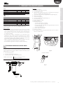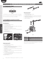
1
humiFog Multizone
ricambi/spare parts
Manuale d’uso
User manual
NO POWER
& SIGNAL
CABLES
TOGETHER
READ CAREFULLY IN THE TEXT!
I n t e g r a t e d
C o n t r o l
S o l u t i o n s
&
E n e r g y
S a v i n g s
ENG
WARNINGS
CAREL INDUSTRIES Hq humidifiers are advanced products, whose operation is
specified in the technical documentation supplied with the product or can be
downloaded, even prior to purchase, from the website www.carel.com. Each
CAREL INDUSTRIES Hq product, in relation to its advanced level of technology,
requires setup/configuration/programming/commissioning to be able to
operate in the best possible way for the specific application. The failure to
complete such operations, which are required/indicated in the user manual,
may cause the final product to malfunction; CAREL INDUSTRIES Hq accepts
no liability in such cases.
The customer (manufacturer, developer or installer of the final equipment)
accepts all liability and risk relating to the configuration of the product in order
to reach the expected results in relation to the specific final installation and/or
equipment. CAREL INDUSTRIES Hq may, based on specific agreements, act as
a consultant for the installation/commissioning/use of the unit, however in no
case does it accept liability for the correct operation of the humidifier and the
final installation if the warnings or suggestions provided in this manual or in
other product technical documents are not heeded. In addition to observing
the above warnings and suggestions, the following warnings must be heeded
for the correct use of the product:
• DANGER OF ELECTRIC SHOCK
• The humidifier contains live electrical components. Disconnect the mains
power supply before accessing inside parts or during maintenance and
installation;
• DANGER OF WATER LEAKS
• The humidifier automatically and constantly fills/drains certain quantities
of water. Malfunctions in the connections or in the humidifier may cause
leaks;
• For isothermal humidifiers: DANGER OF BURNS
• The humidifier contains high temperature components (100°C/212°F);
• For gas-fired isothermal humidifiers: DANGER OF GAS LEAKS
• The humidifier is connected to the gas mains. Malfunctions in the
connections or inside the humidifier may cause gas leaks.
• The installation of the product must include an earth connection, using the
special yellow-green terminal available in the humidifier.
• The environmental and power supply conditions must conform to the
values specified on the product rating labels.
• The product is designed exclusively to humidify rooms either directly or
through distribution systems (ducts). In addition, for adiabatic-water spraypressure humidifiers, humidification also occurs through the atomisation
rack.
• Only qualified personnel who are aware of the necessary precautions and
able to perform the required operations correctly may install, operate or
carry out technical service on the product.
• Only water with the characteristics indicated in this manual must be used
for steam or water vapour production.
• Warning, demineralised drinking water must be used for adiabatic-water
spray-pressure humidifiers (as specified in the manual). In addition, the
particles of water not absorbed by the air must be removed into the droplet
collection tank (in the humidification section) and by the droplet separator
(at the end of the humidification section).
• All operations on the product must be carried out according to the
instructions provided in this manual and on the labels applied to the
product. Any uses or modifications that are not authorised by the
manufacturer are considered improper. CAREL INDUSTRIES Hq declines all
liability for any such unauthorised use.
• Do not attempt to open the humidifier in ways other than those specified
in the manual.
• Observe the standards in force in the place where the humidifier is installed.
• Keep the humidifier out of the reach of children and animals.
• Do not install and use the product near objects that may be damaged when in
contact with water (or condensate). CAREL INDUSTRIES Hq declines all liability
for direct or indirect damage following water leaks from the humidifier.
• Do not use corrosive chemicals, solvents or aggressive detergents to clean
the inside and outside parts of the humidifier, unless specifically indicated
in the user manual.
• Do not drop, hit or shake the humidifier, as the inside parts and the linings
may be irreparably damaged.
• For adiabatic-water spray-pressure humidifiers: the atomised water must be
distributed using a special atomising ‘rack’ or through distribution systems
specified by CAREL INDUSTRIES Hq
• For isothermal appliances: these are designed to produce steam at
atmospheric pressure, and not pressurised steam. CAREL INDUSTRIES Hq
does not recommend and waives all liability for the use of distribution
devices other than those specified.
CAREL INDUSTRIES Hq adopts a policy of continual development.
Consequently, CAREL reserves the right to make changes and improvements
to any product described in this document without prior warning. The
technical specifications shown in the manual may be changed without prior
warning.
The liability of CAREL INDUSTRIES Hq in relation to its products is specified
in the CAREL INDUSTRIES Hq general contract conditions, available on the
website www.carel.com and/or by specific agreements with customers;
specifically, to the extent where allowed by applicable legislation, in no case
will CAREL INDUSTRIES Hq, its employees or subsidiaries be liable for any lost
earnings or sales, losses of data and information, costs of replacement goods
or services, damage to things or people, downtime or any direct, indirect,
incidental, actual, punitive, exemplary, special or consequential damage of any
kind whatsoever, whether contractual, extra-contractual or due to negligence,
or any other liabilities deriving from the installation, use or impossibility to use
the product, even if CAREL INDUSTRIES Hq or its subsidiaries are warned of the
possibility of such damage.
DISPOSAL
The humidifier is made up of metal parts and plastic parts. In reference to
European Union directive 2002/96/EC issued on 27 January 2003 and the
related national legislation, please note that:
1. WEEE cannot be disposed of as municipal waste and such waste must be
collected and disposed of separately;
2. the public or private waste collection systems defined by local legislation
must be used. In addition, the equipment can be returned to the distributor
at the end of its working life when buying new equipment;
3. the equipment may contain hazardous substances: the improper use or
incorrect disposal of such may have negative effects on human health and
on the environment;
4. the symbol (crossed-out wheeled bin) shown on the product or on the
packaging and on the instruction sheet indicates that the equipment has
been introduced onto the market after 13 August 2005 and that it must
be disposed of separately;
5. in the event of illegal disposal of electrical and electronic waste, the
penalties are specified by local waste disposal legislation.
Warranty on the materials: 2 years (from the date of production, excluding
consumables).
Approval: the quality and safety of CAREL INDUSTRIES Hq products are
guaranteed by the ISO 9001 certified design and production system, as well
as by the following marks.
WARNING: separate as much as possible the probe and digital input signal
cables from the cables carrying inductive loads and power cables to avoid
possible electromagnetic disturbance.
Never run power cables (including the electrical panel wiring) and signal
cables in the same conduits.
NO POWER
& SIGNAL
CABLES
TOGETHER
READ CAREFULLY IN THE TEXT!
“humiFog multizone ricambi/spare parts” +030222100 rel. 1.0 - 12.05.2009
3
ENG
Content
1. PREVENTIVE MAINTENANCE
7
1.1 Preventive maintenance of the water filter .................................................. 7
2. PREVENTIVE MAINTENANCE OF THE PUMP
8
2.1 Checking the oil level ....................................................................................... 8
2.2 Changing the oil, gaskets and valves ............................................................. 8
4. REPLACING THE COMPONENTS IN THE CABINET
9
4.1 Motor, pump and related components........................................................ 9
4.2 Replacing the electrical components in the cabinet ............................... 10
5. RACK SPARE PARTS
11
5.1 List of duct distribution system spare parts ............................................. 11
6. REPLACING AND CLEANING THE RACK COMPONENTS12
6.1 Water leaks ....................................................................................................... 12
6.3 Replacement...................................................................................................... 12
7. ROOM DISTRIBUTION SYSTEM SPARE PARTS
13
7.1 List of room distribution system spare parts ............................................. 13
8. REPLACING AND CLEANING THE DISTRIBUTION SYSTEM
COMPONENTS
14
8.1 Water leaks ....................................................................................................... 14
8.2 Cleaning ............................................................................................................ 14
8.3 Replacement .................................................................................................... 14
9. SPARE PARTS FOR CONNECTION BETWEENHUMIFOG
AND THE DISTRIBUTION SYSTEM
15
“humiFog multizone ricambi/spare parts” +030222100 rel. 1.0 - 12.05.2009
5
ENG
Important: change the oil in the pump after the first 50 hours of
operation
Rack and room distribution system
visual inspection
blocked nozzles
solenoid valves
accessories
drains and water
droplet separator
monthly every 2000 h every 4000 h
X
X
X
X
X
Installations in AHUs or ducts must also comply with national maintenance
standards (ASHRAE 12-2000, VDI 6022, UNI 8884, VDI 3803, etc.).
Please note that:
• the personnel in charge of maintenance must reset the hour counter
after having performed the preventive maintenance operations listed
in the columns “after 50 hours”, “every 2000 hours” and “every 4000
hours”. If the hour counter is not reset, the maintenance warnings will
no longer be signalled;
• the personnel in charge of maintenance are responsible for any
malfunctions due to a lack of preventive maintenance. The controller
will show the maintenance warning code “C5” after the first 50 hours
and, subsequently, the routine maintenance warning code “CL” every
2000 hours as a reminder for the following operations;
• failure to change the oil after the first 50 hours of operation may cause
serious damage to the pumps and reduce operating life;
• the maintenance signals do not stop the operation of humiFog.
3
2
4
3
5
1
2
6
1
7
5
60 µm
7
1.1 Preventive maintenance of the water
filter
The filters should be checked monthly, while the 9” filter (Fig. 1.c) should
only be replaced if the pressure difference between the two pressure
gauges in Fig. 1.a is > 0.5 bars.
1. access the water circuit;
2. open the external water supply tap;
3. check the pressure drop across the water filter.
Fig. 1.c
Fig. 1.d
Washable FILTER KIT
4
3
5
2
1
∆P= PIN - PUSC ≤ 0.5 bar?
7
YES= proceed with the remaining
maintenance operations
NO= replace the cartridges
4
3
5
PIN
2
1
POUT
7
4
3
5
Fig. 1.e
2
1
user
monthly every 2000 h every 4000 h
X
X
X
X
Procedure:
1. switch off humiFog;
2. shut off the water supply externally;
3. access the water circuit;
4. drain the filter: open the bottom valve on the filter, press the plug at
the top to completely drain the filter (Fig. 1.b).
5. open the filter: release the nut using the filter tool supplied (Fig. 1.d);
6. replace the cartridge;
7. close the filter (Fig. 1.d);
8. go to the “Y” filter on the regulator (Fig. 1.e);
9. unscrew the filter case;
10. remove and wash the filter;
11. replace the filter;
12. fill the filter with water:
- close the bottom valve on the filter;
- open the water supply tap (external);
- press the black plug on the filter to the right until water is released
around the plug (Fig. 1.c);
- dry the water that leaked out.
13. close the water circuit section;
14. switch on humiFog;
15. the cartridges are made from polypropylene: dispose of in accordance
with local standards/laws.
service
Pump
Check
water filters
check oil level
change oil
replace gaskets and valves
installer
1. PREVENTIVE MAINTENANCE
7
Fig. 1.a
“humiFog multizone ricambi/spare parts” +030222100 rel. 1.0 - 12.05.2009
7
ENG
2. PREVENTIVE MAINTENANCE OF THE PUMP
installer
2.1 Checking the oil level
The oil level should be checked visually every month. The figure shows
the correct oil level in the gauge.
Fig. 2.d
Replacing the valves
Fig. 2.a
The drawing shows the front of the transparent Plexiglas oil level gauge.
user
If the level is lower than the mark shown in the figure, top up with oil to
the correct level; in the event of oil leaks, contact CAREL.
1.
2.
3.
4.
5.
6.
7.
8.
switch off humiFog;
shut off the water supply externally;
access the water circuit;
unscrew the three caps on the top and front of the pump head;
replace the 6 existing valves;
tighten the three caps on the top and front of the pump head;
close the water circuit section;
switch on humiFog.
2.2 Changing the oil, gaskets and valves
The oil must be changed every 4000 operating hours, also replacing the
pump gaskets and valves.
Changing the oil
service
1.
2.
3.
4.
5.
6.
7.
8.
9.
10.
switch off humiFog;
shut off the water supply externally;
access the water circuit;
remove the yellow cap from the top of the pump and open the oil
drain plug on the rear of the pump;
drain the oil and close the plug;
dispose of the oil according to local standards;
fill with (ISO 68) SAE 20 W - 30 W oil to the level indicated (around
350 ml of oil);
close the top oil cap;
close the water circuit section;
switch on humiFog.
4
Fig. 2.e
Spare part codes:
UAKVGO1500
UAKVGO1800
UAKVGX1500
4
UAKVGX1800
Fig. 2.b
Fig. 2.c
Replacing the gaskets
1.
2.
3.
4.
5.
6.
7.
8.
9.
10.
11.
12.
8
switch off humiFog;
shut off the water supply externally;
access the water circuit;
disconnect the wiring from the pressure probe, the HP switch, the
safety solenoid valve and the NTC probe (Fig. 4.b);
disconnect the hose from the pump outlet;
unscrew the 8 hexagonal screws that couple the head of the pump
to the sump;
replace the existing gaskets;
retighten the 8 hexagonal screws that couple the head of the pump
to the sump;
connect the hose to the pump outlet;
connect the wiring to the pressure probe, the HP switch, the safety
solenoid valve and the NTC probe;
close the water circuit section;
switch on humiFog.
“humiFog multizone ricambi/spare parts” +030222100 rel. 1.0 - 12.05.2009
Gasket and valve kit for UA 100-200-320 with brass pump
Gasket and valve kit for UA 460-600 with brass pump.
Gasket and valve kit for UA 100-200-320 with stainless
steel pump.
Gasket and valve kit for UA 460-600 with stainless steel
pump
The hour counter can be reset under the “maintenance -> hour counter”,
and requires the maintenance password.
ENG
4. REPLACING THE COMPONENTS IN THE CABINET
4.1 Motor, pump and related components
user
installer
This chapter provides explanations on how to replace the motor, the
pump and all the external components connected directly to these.
Fig. 4.b
Important: do not lose the pin between the motor and the pump
Fig. 4.a
The motor can now be replaced (continue for the pump)
the gaskets”;
2. remove the power cable from the motor, paying attention to the
terminals that the cables are connected to!
3. remove the temperature probe (Fig. 4.b ref. F);
4. remove the connectors from the pressure probe, (Fig. 4.b ref. B), the
maximum pressure switch (Fig. 4.b ref. C) and the safety valve (Fig.
4.b ref. D);
5. unscrew the pump support from the cabinet;
6. remove the motor and pump from the cabinet;
B
A
C
D
F
E
9. remove all the necessary components, in the sequence shown;
10. remove the recirculation valve in the sequence shown; the pump can
now be replaced;
11. reassemble all the components in the reverse order;
12. use liquid Teflon for the high pressure connections. Wait at least 6
13.
14.
15.
16.
hours for the liquid Teflon to dry before opening the water supply to
the assembled parts;
open external water supply;
fill the water filters (Fig. 1.c);
close the water circuit section;
switch on humiFog.
UAKP100Y00
UAKP100Y01
UAKP100Y10
UAKP100Y11
Brass pump kit for UA100
Stainless steel pump kit for UA100
Brass pump kit for UA100 + sm
Stainless steel pump kit for UA100 +sm
UAKP200Y00
UAKP200Y01
UAKP200Y10
UAKP200Y11
Brass pump kit for UA200
Stainless steel pump kit for UA200
Brass pump kit for UA200 + sm
Stainless steel pump kit for UA200 +sm
UAKP320Y10
UAKP320Y11
Brass pump kit for UA320 + sm
Stainless steel pump kit for UA320 +sm
UAKP460Y10
UAKP460Y11
Brass pump kit for UA460 + sm
Stainless steel pump kit for UA460 +sm
UAKP600Y10
UAKP600Y11
Brass pump kit for ua600 + sm
Stainless steel pump kit for UA600 +sm
UAKM075F50
1HP electric motor kit for UA100HD-UA200HDUA100ZD-UA200ZD
2HP electric motor kit for UA320HD-UA460HDUA320ZD-UA460ZD
3HP electric motor kit for UA600HD UA600ZD
UAKM150F50
Fig. 4.b
Key:
A motor connection cover
B pressure transducer connector
C HP pressure switch connector
D bypass solenoid valve connector
E temperature valve spade connector
F NTC temperature probe
UAKM220F50
UAKM075F60
UAKM150F60
UAKM220F60
1HP electric motor kit for UA100HU-UA200HUUA100ZU-UA200ZU
2HP electric motor kit for UA360HU-UA420HUUA360ZU-UA420ZU
3HP electric motor kit for UA600HU-UA600ZU
7. unscrew the screws between the pump and the motor. If the pump
is hard to remove, use the coupling screws as extractors (Fig. 4.c);
8. unscrew the motor from the plate.
“humiFog multizone ricambi/spare parts” +030222100 rel. 1.0 - 12.05.2009
9
service
1. repeat points from 1 to 6, in paragraph 2.2 sub-paragraph “Replacing
ENG
4.2 Replacing the electrical components in
the cabinet
installer
1
2
7
3
user
6
5
4
service
8
Position
1
2
3
4
5
6
7
8
part code
UAKTRB0000
UAKVFD0750
UAKVFD1500
UAKVFD2200
URKTR20000
UAKPCO3H00
UAKPCO3Z00
UAKPCO3S00
PCOUMID2000
UAKREL24040
UAKFUSETR0
UAKFUSEVA0
description
400 VA transformer
UA100/200***** - inverter 0.75 KW 230 V
UA320/460***** - inverter 1.5 KW 230 V
UA600***** - inverter 2.2 KW 230 V
100 VA transformer
pCO3 large for UAXXXHX3XX
pCO3 large for UAXXXZX3XX
pCO3 large for UAXXXSX3XX
pCO umid
24 V relay kit, 4 changeover contacts
transformer fuse kit
valve fuse kit
Tab. 4.a
Replacing the inverter
1.
2.
3.
4.
5.
disconnect the cables;
carefully unscrew the inverter;
replace with a new inverter;
reconnect the cables;
check the correct earthing of the shields on the control cable (li1, +2
) and power cable (U, V, W, PE);
6. reposition the cover on the terminal;
7. close the electrical section;
8. switch on humiFog.
10
“humiFog multizone ricambi/spare parts” +030222100 rel. 1.0 - 12.05.2009
ENG
ref. description
60 frame top side
code
14C585A1**
61
frame bottom side
14C470A1**
62
side shoulder
14C585A1**
63
14C470A1**
64
vertical manifold support
bar
horizontal manifold
65
vertical manifold
98C585P2**
70
66
1309610AXX
60
67
69
M/F G1/4” elbow
connector
G1/8” hose
24 V 50 Hz NC stainless
steel solenoid valve
24 V 50 Hz NO stainless
steel solenoid valve
kit of 15 M3 screws for
adjusting manifold angle
M G1/8” plug
atomising nozzle MTP1 2.8
kg/h marked “1”
atomising nozzle MTP2 4.0
kg/h marked “2”
kit of 8 brackets
kit for vertical manifold
assembly with screws and
washers
M 1/8” NPT plug
atomising nozzle MTP1
1.5 kg/h
kit of washers and M6 bolts
for complete rack assembly
67
98C585P2**
64
69
66
70
63
77
62
72
73
74
75
62
76
77
65
77
72
70
78
79
14C531A097
1312079AXX
1312115AXX
user
Important:
• use liquid Teflon guaranteed for water pressures up to 100 bars to seal
the water connections;
• wait 3 hours for the Teflon to set.
notes
** = 00 to 15 based on
the length
** = 00 to 15 based on
the length
** = 20 to 35 based on
the length
** = 40 to 55 based on
the length
** = 80 to 95 based on
the length
** = 60 to 75 based on
the length
UAKVITIM30
1309633AXX
UAKMTP1000
UAKMTP2000
UAKS000000
UAKMOR0000
1309639AXX
UAKMTP0000
UAKVITIM60
Tab. 5.a
61
76
Fig. 5.a
79
74
0
75
1
2
73
78
Fig. 5.b
“humiFog multizone ricambi/spare parts” +030222100 rel. 1.0 - 12.05.2009
11
service
5.1 List of duct distribution system spare
parts
installer
5. RACK SPARE PARTS
ENG
6. REPLACING AND CLEANING THE RACK COMPONENTS
NC valves and direct connections
Important:
installer
• use liquid Teflon guaranteed for water pressures up to 100 bars to seal
the water connections;
• wait 3 hours for the Teflon to set.
11. solenoid valves: remove the coil;
12. unscrew part “H”;
13. unscrew the NC solenoid valve/direct connectors with the G18”
nipple;
14. unscrew the G1/8” nipple from the valve body/direct connector;
15. unscrew the adapter for the hose “E”.
6.1 Water leaks
• repair by using liquid Teflon on all the water connections without
11
15
O-rings or rubber gaskets;
• if necessary, replace the components as described in the following
paragraph.
Remove the components to be cleaned
1. remove any components not made from stainless steel (for example
nozzle o-rings);
service
user
2. soak the stainless steel parts in a solution of water and vinegar for 12
hours (use 4/5 water and 1/5 vinegar);
3. rinse with water;
4. for particularly resistant scale use pure vinegar for 12 hours;
5. reassemble all the components in the reverse order.
Fig. 6.b
6.3 Replacement
Horizontal manifold
1. switch off humiFog;
2. close the external water supply tap;
3. remove the connectors from the solenoid valves.
16.
17.
18.
19.
Nozzles and plugs
Important: remember the positions of the nozzles/plugs
4. Replace with extreme care.
solenoid valves: remove the coil;
unscrew all the parts marked “H”
remove the bolts “D”;
unscrew the NC solenoid valve/direct connectors, with the G18”
nipple;
20. remove the elbow connector for draining the NO solenoid valve;
21. unscrew the M/F G1/4” elbow.
18
23
Vertical manifolds
Important:
• remember the angle of each manifold;
• make sure the NO valve and direct connection remain intact;
5.
6.
7.
8.
9.
10.
remove the hose;
remove the coil from the NO solenoid valve;
remove the screw “PH0”;
remove the bolts “D”;
remove the adapter “E” for connecting the hose;
unscrew the NO solenoid valve.
Fig. 6.c
5
...
10
Fig. 6.a
12
“humiFog multizone ricambi/spare parts” +030222100 rel. 1.0 - 12.05.2009
ENG
user
installer
7. ROOM DISTRIBUTION SYSTEM SPARE PARTS
service
Fig. 7.a
7.1 List of room distribution system spare
parts
ref.
73
74
78
79
200
201
202
206
207
208
209
210
211
212
213
214
215
description
M G1/8” plug
Atomising nozzle MTP1 2.7 l/h
M 1/8” NPT plug
Atomising nozzle MTP0 1.45 l/h
Central drain solenoid valve kit
Drain solenoid valve kit for
manifold
Capacity-control solenoid
valve kit
Manifold with 4 holes for
nozzles, step 600
Manifold with 7 holes for
nozzles, step 300
Extension kit d.10 L= 3 m; one
stainless steel pipe
Extension kit d.10 L= 6 m; two
stainless steel pipes
extension pipe d. 10 L= 12 m
(four stainless steel pipes)
extension pipe d.10 L= 18 m;
six stainless steel pipes
straight terminal for d.10 pipe
straight G1/4”M terminal for
d.10 pipe
straight G1/8”M terminal for
d.10 pipe
female “T” for d.10 pipe
female elbow for d.10 pipe
female elbow for d.10 x1/8”
pipe
female “X” for d.10 pipe
code
1309633AXX
UAKMTP1000
1309639AXX
UAKMTP0000
UAKCD0000*
UAKVAL000*
notes
Ref. Fig. 5.b
UAKVALNC00
UAKC4FP600
4 holes on 1 side
UAKC7FP300
4+3 holes on 2
sides
ref fig 7a
UAKT030000
UAKT060000
UAKT012000
UAKT018000
UAKTD00000
UAKTD14000
UAKTD18000
UAKTT00000
UAKTG00000
UAKTG18000
UAKTX00000
Tab. 7.a
*: 0= non-aggressive water; 1= aggressive water.
“humiFog multizone ricambi/spare parts” +030222100 rel. 1.0 - 12.05.2009
13
ENG
8. REPLACING AND CLEANING THE DISTRIBUTION SYSTEM COMPONENTS
installer
switched off and the water supply tap is closed. Water may leak out when
disconnecting the various water circuit components.
6. unscrew the valve inlet connection;
7. unscrew the plug from the valve water outlet that is not used.
3
7
8.1 Water leaks
A. repair by using liquid Teflon on all the water connections without
O-rings or rubber gaskets;
B. if necessary, replace the components as described in paragraph 5.
4.2
OU
TLE
INL
IN
T
OU
ET
8.2 Cleaning
TLE
T
Fig. 8.b
user
1. remove the components to be cleaned;
2. remove any components not made from stainless steel (for example
nozzle o-rings);
3. soak the stainless steel parts in a solution of water and vinegar for 12
hours (use 4/5 water and 1/5 vinegar);
4. rinse with water;
5. for particularly resistant scale use pure vinegar for 12 hours;
6. reassemble all the components in the reverse order.
Replacing the NO drain valves at the end of the line
8.
9.
10.
11.
remove the electrical connector;
disconnect the water drain hose;
unscrew the drain pipe fitting from the valve;
unscrew the valve and the nipple from the distribution manifold.
INT
8
11
1. switch off humiFog;
2. close the external water supply tap.
OU
TLE
T
Replacing nozzles and plugs
Fig. 8.c
Important: remember the positions of the nozzles (A) and plugs (B).
Replace with extreme care.
Replacing the NO drain valves between the pump and
the distribution system
A
12.
13.
14.
15.
remove the electrical connector;
disconnect the water drain hose;
unscrew the drain pipe fitting from the valve;
unscrew the valve and the nipple from the “T”.
12
15
TO NOZZLES
service
8.3 Replacement
LET
B
MP
OM
FR
PU
INLET
Fig. 8.a
OUTLET
Replacing the NC on-off valves
Important: the on-off valves are “normally closed” solenoid valves; the
valve body has three F G1/8” connections (see the figure on the side).
Remember that the water inlet is the hole in the centre, while the two
side holes are the two outlets available:
• individually, closing the outlet that is not used with a M G1/8” plug;
• together if this simplifies the water connections.
3. remove the electrical connector;
4. disconnect the pressurised water supply pipe;
5. unscrew the valve from the fittings;
14
“humiFog multizone ricambi/spare parts” +030222100 rel. 1.0 - 12.05.2009
Fig. 8.d
ENG
user
installer
9. SPARE PARTS FOR CONNECTION BETWEEN
HUMIFOG AND THE DISTRIBUTION SYSTEM
Fig. 9.a
Short hose kit (L= 2 m)
Kit of 2 short hoses (L= 2 m) + Extension pipe kit (L= 1.5 m)
81
service
80
Fig. 9.b
Extension hose kit (L= see Tab. 9.a)
Fig. 9.c
Extension pipe kit (L= 1.5 m)
83
82
Fig. 9.d
Ref.
80
81
82
83
99
208
208
208
208
209
210
211
212
213
214
215
Fig. 9.e
Description
Short connection kit L= 2 m
Hose and adapter
Long connection kit L= 5.5 m. Two hoses, one steel pipe and adapters
Extension pipe kit L= 1.5 m. One stainless steel pipe and adapter
Extension hose kit L= 2 m
Extension kit L= 0.5 m
Extension kit L= 1 m
Extension kit L= 5 m
Extension kit L= 10 m
Extension kit L= 20 m
Brass line drain valve
Stainless steel line drain valve
Extension pipe kit dia. 10 L= 3 m; One stainless steel pipe
Extension pipe kit dia. 10 L= 6 m; two stainless steel pipes
Extension pipe kit dia. 10 L= 12 m; Four stainless steel pipes
Extension pipe kit dia. 10 L= 18 m; Six stainless steel pipes
Straight terminal for dia. 10 pipe
Straight M G1/4” terminal for dia. 10 pipe
Straight M G1/8” terminal for dia. 10 pipe
Female “T” for dia. 10 pipe
Female elbow for dia. 10 pipe
Female 1/8” elbow for dia. 10 pipe
Female “X” for dia. 10 pipe
Code
UAKT100000
Notes
UAKT200000
UAKT300000
UAKT400000
UAKT500000
UAKT600000
UAKT700000
UAKT800000
UAKT900000
UAKCD00000
UAKCD00001
UAKT030000
UAKT060000
UAKT012000
UAKT018000
UAKTD00000
UAKTD14000
UAKTD18000
UAKTT00000
UAKTG00000
UAKTG18000
UAKTX00000
Tab. 9.a
“humiFog multizone ricambi/spare parts” +030222100 rel. 1.0 - 12.05.2009
15
CAREL INDUSTRIES - Headquarters
Via dell’Industria, 11 - 35020 Brugine - Padova (Italy)
Tel. (+39) 049.9716611 - Fax (+39) 049.9716600
e-mail: [email protected] - www.carel.com
+030222100 - rel. 1.0 - 12.05.2009
Agenzia / Agency: