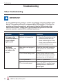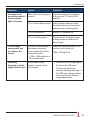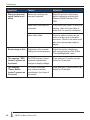
1
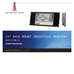
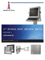
19" UNIVERSAL MOUNT INDUSTRIAL MONITOR REVISION E USER MANUAL Model No. HIS-UM19- _ _ _ E Table of Contents Safety and Regulatory Information��������������������������������������������������������������������������������3 FCC Notice����������������������������������������������������������������������������������������������������������������������������� 3 Hazardous Locations�������������������������������������������������������������������������������������������������������������� 4 Waste Electrical and Electronic Equipment Directive (WEEE)����������������������������������������������� 4 Mechanical Drawings������������������������������������������������������������������������������������������������������5 Front View������������������������������������������������������������������������������������������������������������������������������� 5 Rear View������������������������������������������������������������������������������������������������������������������������������� 5 Side View�������������������������������������������������������������������������������������������������������������������������������� 6 Installation Instructions��������������������������������������������������������������������������������������������������7 Step 1: Prepare for Installation���������������������������������������������������������������������������������������������� 7 Step 2: Bench-test Configuration������������������������������������������������������������������������������������������� 8 Install Cable Connections������������������������������������������������������������������������������������������������������������������ 8 Install Touchscreen���������������������������������������������������������������������������������������������������������������������������� 9 Step 3: Install the Monitor���������������������������������������������������������������������������������������������������� 11 Install Cable Exit Cover Plate�����������������������������������������������������������������������������������������������������������11 Mount the Monitor���������������������������������������������������������������������������������������������������������������������������� 12 Video Settings����������������������������������������������������������������������������������������������������������������15 Setting the Timing Mode������������������������������������������������������������������������������������������������������� 15 Control Panel Buttons����������������������������������������������������������������������������������������������������������� 16 OSD and Power Lock Settings��������������������������������������������������������������������������������������������� 17 On-Screen Display (OSD) Menus����������������������������������������������������������������������������������������� 18 Auto Image Adjust Menu������������������������������������������������������������������������������������������������������������������ 19 Contrast / Brightness Menu������������������������������������������������������������������������������������������������������������� 19 Input Select Menu���������������������������������������������������������������������������������������������������������������������������� 19 Color Adjust Menu���������������������������������������������������������������������������������������������������������������������������� 20 Information Menu����������������������������������������������������������������������������������������������������������������������������� 21 Manual Image Adjust Menu������������������������������������������������������������������������������������������������������������� 21 Setup Menu�������������������������������������������������������������������������������������������������������������������������������������� 22 Memory Recall Menu����������������������������������������������������������������������������������������������������������������������� 22 Cleaning Instructions����������������������������������������������������������������������������������������������������23 Troubleshooting������������������������������������������������������������������������������������������������������������24 Video Troubleshooting���������������������������������������������������������������������������������������������������������� 24 Touchscreen Troubleshooting����������������������������������������������������������������������������������������������� 27 Specifications����������������������������������������������������������������������������������������������������������������28 Display���������������������������������������������������������������������������������������������������������������������������������� 28 Environmental����������������������������������������������������������������������������������������������������������������������� 28 Video������������������������������������������������������������������������������������������������������������������������������������� 29 Electrical������������������������������������������������������������������������������������������������������������������������������� 29 Functional����������������������������������������������������������������������������������������������������������������������������� 29 Physical�������������������������������������������������������������������������������������������������������������������������������� 30 Compliances and Certifications�������������������������������������������������������������������������������������������� 30 Warranty Statement�������������������������������������������������������������������������������������������������������31 2 UM19E User Manual, February 2011 Safety and Regulatory Information Safety and Regulatory Information ! WARNING! To prevent fire or shock hazard, do not expose live components to rain or moisture. Dangerously high voltages are present inside the unit. Do not disassemble the unit. Refer servicing to qualified personnel only. This equipment is not intended for use in critical applications where its failure to operate would create immediate life threatening circumstances. Applications including, but not limited to, nuclear reactor control, aerospace navigation systems and life support systems are not appropriate for this product. To be covered by UL 60950 3rd Edition, the monitor covered in this report is required to be used with a Listed computer, and the socket-outlet shall be installed near the equipment and shall be easily accessible. FCC Notice This equipment has been tested and found to comply with the limits for a Class A digital device, pursuant to Part 15 of the FCC Rules. These limits are designed to provide reasonable protection against harmful interference when the equipment is operated in a commercial environment. This equipment generates, uses, and can radiate radio frequency energy and, if not installed and used in accordance with the instruction manual, may cause harmful interference to radio communications. Operation of this equipment in a residential area is likely to cause harmful interference in which case the user will be required to correct the interference at his own expense. Any changes or modifications not expressly approved by the grantee of this device could void the user’s authority to operate the device. UM19E User Manual, February 2011 3 Safety and Regulatory Information Hazardous Locations The following applies only to monitors rated for hazardous locations (model numbers HIS-UM19- _ _ HE): This equipment is suitable for use in Class I, II & III, Division 2, Groups A, B, C, D, F, and G or non-hazardous locations only. WARNING – EXPLOSION HAZARD – Do not disconnect equipment unless power has been removed or the area is known to be non-hazardous. WARNING – EXPLOSION HAZARD – Substitution of any components may impair suitability for Class I, II & III, Division 2 Locations. Waste Electrical and Electronic Equipment Directive (WEEE) The following information is only for EU-member states: The mark shown to the right is in compliance with the Waste Electrical and Electronic Equipment Directive 2002/96/EC (WEEE). The mark indicates the requirement NOT to dispose of the equipment as unsorted municipal waste, but use the return and collection systems according to local law. Users should contact their supplier and check the terms and conditions of the purchase contract. When purchased directly from Hope Industrial Systems, you may contact technical support for disposal arrangements. 4 UM19E User Manual, February 2011 Mechanical Drawings Mechanical Drawings Front View 467.4 mm (18.40") 380.8 mm (14.99") 397.5 mm (15.65") 305.6 mm (12.03") Rear View 467.4 mm (18.40") 397.5 mm (15.65") CABLE ENTRY UM19E User Manual, February 2011 5 Mechanical Drawings Side View 72.1 mm (2.84") 34.3 mm (1.35") 198.8 mm (7.82") KVM EXTENDER (optional) Side Mounting Holes 1/4"-20 Internal Thread x 0.625" Deep 124.5 mm (4.90") 176.6 mm (6.95") KEYBOARD (optional) 6 UM19E User Manual, February 2011 Installation Instructions Installation Instructions Step 1: Prepare for Installation IMPORTANT! Perform the following steps BEFORE installation of the monitor. 1. Ensure that sufficient power is available and a readily accessible disconnect device is incorporated in the building installation wiring. 2. Ensure that sufficient space is available to allow for proper air flow into and out of the unit. 3. Ensure that the air temperature around the unit (top and bottom) will not exceed the rated specifications of the unit. ! ff The maximum rated temperature for the HIS-UM19 is 50°C (122°F). ff Remember that even though this product is designed to operate at 50°C, the life span of any electronic device is shortened when it is consistently operated at high temperatures. Therefore, it is wise to take steps to keep the temperature of the ambient air around the unit as low as possible. 4. Ensure that the ambient humidity of the air around the unit does not exceed the specifications of the unit. ff The maximum rated humidity for the HIS-UM19 is 90% non-condensing. UM19E User Manual, February 2011 7 Installation Instructions Step 2: Bench-test Configuration Make sure everything works before installing into the production environment. TIP! If using a KVM extender, please refer to the installation instructions included with the KVM extender module. It is particularly important to bench-test the full configuration prior to final installation. This will help to identify and troubleshoot any system issues while configuration changes may still be easily made. Install Cable Connections The cable ports are located on the rear of the monitor. Refer to the following instructions to connect power, video, and touchscreen (if applicable) to your monitor. Video Connection The HIS-UM19 supports analog and digital video. Analog Video Connection Connect one end of the VGA video cable to the HD-15 input port on the rear of the monitor. Connect the other end to the analog video output port on the host computer. Digital Video Connection Connect one end of the DVI video cable to the DVI-D input port on the rear of the monitor. Connect the other end to the digital video output port on the host computer. Power Connection The HIS-UM19 is powered by 120/240 VAC, 1.2/0.6 A, 60/50 Hz. Connect the AC power cable to the power input port on the rear of the monitor. Connect the other end into a nearby outlet. 8 UM19E User Manual, February 2011 Installation Instructions Install Touchscreen Applies to touchscreen monitors only. Instructions below apply to Windows systems. Both Serial and USB ports are present on all touchscreen monitors, but only one should be used to connect the touchscreen interface to the monitor. All touchscreen monitors are shipped with a CD-ROM that contains documentation and drivers for all major operating systems. To be sure that you have the most current information, please check the following Internet address: http://www.HopeIndustrial.com/Touchscreen_Drivers.htm IMPORTANT! If you will be using a Serial connection, connect the Serial cable first, and then install the touchscreen driver. If you will be using a USB connection, install the touchscreen driver first, and then connect the USB cable. Serial (RS-232) Connection 1. Connect one end of the Serial cable to the Serial input port on the rear of the monitor. Connect the other end to the Serial port on the host computer. Tighten the captive screws on the cable connectors to ensure adequate strain relief. 2. Select the appropriate driver for your operating system. a. If downloading from the web address listed above, select the appropriate driver for your operating system. b. If using the included CD, insert it into the host computer's CD-ROM drive. If the CD does not automatically run, browse the contents of the CD and open the ReadMe.htm file in a web browser. Select the appropriate driver. NOTE: For Windows 7 and Vista operating systems, you must save the driver to a location on your hard drive, then run using elevated privileges by right-clicking on the file and selecting "Run as administrator". 3. Click to "Run" the software when prompted. Follow on-screen instructions to download and execute the touchscreen driver installation. UM19E User Manual, February 2011 9 Installation Instructions USB Connection 1. Select the appropriate driver for your operating system. a. If downloading from the web address listed above, select the appropriate driver for your operating system. b. If using the included CD, insert it into the host computer's CD-ROM drive. If the CD does not automatically run, browse the contents of the CD and open the ReadMe.htm file in a web browser. Select the appropriate driver. NOTE: For Windows 7 and Vista operating systems, you must save the driver to a location on your hard drive, then run using elevated privileges by right-clicking on the file and selecting "Run as administrator". 2. Click to "Run" the software when prompted. Follow on-screen instructions to download and execute the touchscreen driver installation. 3. A cable retention bracket comes installed on the USB port on the rear of the monitor and will help to secure the cable and ensure adequate strain relief. Route one end of the USB cable through the retention bracket and connect it to the USB input port on the monitor. Connect the other end to the USB port on the host computer. Calibrate the Touchscreen Once the driver has finished installing, you are ready to calibrate the touchscreen. Open the touchscreen's Control Panel, located in the host computer's Control Panel. NOTE: The latest versions of Windows touchscreen drivers provided by Hope Industrial have an "Enhanced Calibration Mode" option. If applicable to your particular driver, this setting may be found in the touchscreen's Control Panel under the "Mode" tab. 10 UM19E User Manual, February 2011 Installation Instructions Step 3: Install the Monitor Once you have completed the full bench-test configuration and confirmed that all components are working properly, you are ready for final installation and mounting of the monitor. ! WARNING! HIS will not assume liability for damage to internal electronics due to improper installation. Contact HIS if you need additional assistance. Install Cable Exit Cover Plate Installation instructions vary slightly depending on the Cable Exit Cover Plate you ordered. Complete installation instructions are shipped with each Cover Plate configuration and may also be found on our website at the following addresses: Compression Gland (CP-GL Series): http://www.HopeIndustrial.com/Installations/99033.pdf Compression Gland (CP-RG1 Series): http://www.HopeIndustrial.com/Installations/99071.pdf Conduit Cable Exit (CP-CON Series): http://www.HopeIndustrial.com/Installations/99075.pdf PermaGland (CP-PG Series): http://www.HopeIndustrial.com/Installations/99076.pdf Pilot Hole Cover Plate (CP-BLNK Series): http://www.HopeIndustrial.com/Installations/99077.pdf UM19E User Manual, February 2011 11 Installation Instructions Mount the Monitor HIS offers a variety of mounting options for your Universal Mount monitor. Individual installation instructions are shipped with the following products and may also be found on our website at the addresses listed below. Heavy Industrial Yoke Mounts The standard yoke may be used alone, with our benchtop mounting kit for through-surface cable routing, or with our pedestal mount for free-standing applications. Complete installation instructions are shipped with the following products and may also be found on our website at the following addresses: Yoke Mounting Hardware: http://www.HopeIndustrial.com/Installations/99025.pdf YB-N12-KIT (for YB _ _ -BLK-N12 Series): http://www.HopeIndustrial.com/Installations/99026.pdf Yoke Benchtop Kit (for YB Series): http://www.HopeIndustrial.com/Installations/99027.pdf Heavy Industrial Pedestal Mounts Our Yoke and Pedestal mount allows full range of pan and tilt motion, while our Fixed Pedestal mount provides a sturdy solution when a non-adjustable mount is acceptable. Complete installation instructions are shipped with the following products and may also be found on our website at the following addresses: Fixed Pedestal: http://www.HopeIndustrial.com/Installations/99043.pdf Yoke Mounting Hardware: http://www.HopeIndustrial.com/Installations/99025.pdf YB-N12-KIT (for YB _ _ -BLK-N12 Series): http://www.HopeIndustrial.com/Installations/99026.pdf Yoke Benchtop Kit (for YB Series): http://www.HopeIndustrial.com/Installations/99027.pdf 12 UM19E User Manual, February 2011 Installation Instructions Heavy Industrial Arm Mounts Our wall arm mounting options range from solid wall yoke to fullyarticulating arms. Complete installation instructions are shipped with the following products and may also be found on our website at the following addresses: Wall Mount Arms (for YA _ _ -15 and YA _ _ -24 Series): http://www.HopeIndustrial.com/Installations/99090.pdf Wall Yoke (for YW _ _ -07 Series): http://www.HopeIndustrial.com/Installations/99091.pdf VESA Radial Arm The VESA Radial Arm mount is designed to suspend our Universal Mount monitors above a working area. VESA Wall Mount Bracket The VESA Wall Mount Bracket allows simple, effective mounting of our Universal Mount monitors to any vertical surface. VESA Benchtop Stand The VESA Benchtop Stand allows easy, stable positioning of our Universal Mount monitors on any flat surface. UM19E User Manual, February 2011 13 Installation Instructions All HIS Universal Mount monitors come standard with a 100 mm square VESA mounting pattern with M4 threads. Below is the VESA mounting diagram for HIS Universal Mount monitors. Detailed installation instructions for specific VESA mounting options are shipped with the product and may also be found on our website at the following address: http://www.HopeIndustrial.com/Installations/99034.pdf IMPORTANT! If using VESA mounting screws not supplied by HIS, ensure they do not protrude into the enclosure more than 12.7 mm (0.5"). VESA MOUNTING PATTERN (100 mm x 100 mm) MOUNTING PLATE M4 SCREWS NYLON WASHERS UNIVERSAL MOUNT MONITOR RUBBER WASHERS KEYBOARD (OPTIONAL) 14 UM19E User Manual, February 2011 Video Settings Video Settings Setting the Timing Mode Setting the timing mode of your computer graphics adapter (or other video source) is important for maximizing the quality of the screen image and for minimizing eye strain. The timing mode consists of the resolution (e.g. 1280 x 1024) and refresh rate (or vertical frequency; e.g. 60 Hz). After setting the timing mode, use the On-Screen Display (OSD) controls to adjust the screen image. TIP! For the best picture quality, set your computer graphics adapter timing mode to: VESA 1280 x 1024 @ 60 Hz Please refer to the computer graphics adapter manufacturer's manual for instructions on setting the resolution and timing mode. In Microsoft Windows, these settings may be found at the following location: ff ME, 2000, XP: Control Panel > Display > Settings ff Vista: Control Panel > Personalization > Display Settings ff Windows 7: Control Panel > Appearance and Personalization > Adjust Screen Resolution ! WARNING! Do not set the graphics card in your computer to exceed the maximum refresh rate of 75 Hz; doing so may result in permanent damage to your display. UM19E User Manual, February 2011 15 Video Settings Control Panel Buttons Use the control panel buttons located on the back of the monitor to display and adjust various settings on the On-Screen Display (OSD) menu. CONTROL PANEL BUTTONS 1. To display the Main Menu, press button [1]. NOTE: All OSD menus and adjustments screens disappear automatically after 15 seconds. This is adjustable through the OSD timeout setting in the Setup menu. 2. To select a control to adjust, press the up [▲] or down [▼] button to scroll through the menu. 3. Press button [2] to open the menu for a selected control. 4. To adjust the control, press the up [▲] or down [▼] button. 5. To save the adjustments and return to the main OSD menu, press button [1] once. To exit the OSD menu, press button [1] twice. 16 UM19E User Manual, February 2011 Video Settings Button Control Functions Up / Contrast Adjust When the OSD menu IS NOT displayed: • Shortcut to Contrast Adjust. When the OSD menu IS displayed: • Scrolls up and adjusts items in the menu up. Down / Brightness When the OSD menu IS NOT displayed: • Shortcut to Brightness. When the OSD menu IS displayed: • Scrolls down and adjusts items in the menu down. Power • Turns the monitor on and off. • The Power Indicator light glows blue during normal operation and orange when the monitor is in Power Saving mode. Enter • Displays the control screen for the highlighted control. • Toggles between two controls on some screens. Menu • Opens the OSD menu. • Exits the OSD menu and saves adjustments. OSD and Power Lock Settings ff OSD Lock: Press and hold [1] and the up [▲] button for 10 seconds. If any buttons are pressed the message OSD Locked will display for 5 seconds. ff OSD Unlock: Press and hold [1] and the up [▲] button again for 10 seconds. ff Power Button Lock: Press and hold [1] and the down [▼] button for 10 seconds. If the power button is pressed, the message Power Button Locked will display for 5 seconds. With or without this setting, after a power failure, your monitor's power will automatically turn ON when power is restored. ff Power Button Unlock: Press and hold [1] and the down [▼] button again for 10 seconds. UM19E User Manual, February 2011 17 Video Settings On-Screen Display (OSD) Menus To open the OSD menu, press button [1] once. The following screen will appear: Main Menu Description Auto Image Adjust Automatically sizes, centers, and fine tunes the video signal to eliminate waviness and distortion. Contrast / Brightness Includes the Contrast and Brightness functions. Input Select Allows the user to toggle between inputs. Color Adjust Provides several color adjustment modes. Information Displays the timing mode (video signal input). Manual Image Adjust Includes the H./V. Position, Horizontal Size, Fine Tune, Sharpness, and Eco Mode functions. Setup Menu Includes the Language Select, Resolution Notice, OSD Position, OSD Timeout, and OSD Background functions. Memory Recall Returns adjustments back to factory settings. 18 UM19E User Manual, February 2011 Video Settings Auto Image Adjust Menu The Auto Image Adjust menu automatically sizes, centers, and fine tunes the video signal to eliminate waviness and distortion. NOTE: Auto Image Adjust works with most common video cards. If this function does not work on your display, lower the video refresh rate to 60 Hz and set the resolution to its pre-set value. Contrast / Brightness Menu The Contrast/Brightness menu includes the Contrast and Brightness functions. Contrast / Brightness Menu Contrast Description • Adjusts the difference between the image background (black level) and the foreground (white level). • This feature may also be accessed by pressing the up [▲] button outside of the OSD menu. Brightness • Adjusts the background black level of the screen image. • This feature may also be accessed by pressing the down [▼] button outside of the OSD menu. Input Select Menu The Input Select menu allows the user to toggle between inputs if there is more than one computer connected to the display. UM19E User Manual, February 2011 19 Video Settings Color Adjust Menu The Color Adjust menu provides several color adjustment modes, including preset color temperatures and a User Color mode which allows independent adjustment of red (R), green (G), and blue (B). The factory setting for this product is 6500K (6500 Kelvin). Color Adjust Menu Description sRGB This is quickly becoming the industry standard for color management, with support being included in many of the latest applications. Enabling this setting allows the LCD to more accurately display colors the way they were originally intended. NOTE: Enabling the sRGB setting will cause the Contrast and Brightness adjustments to be disabled. 9300K Adds blue to the screen image for cooler white (used in most office settings with fluorescent lighting). 6500K Adds red to the screen image for warmer white and richer red. 5400K Adds green to the screen image for a darker color. User Color Individual adjustments for red (R), green (G), and blue (B). 1. To select color (R, G, or B) press button [2]. 2. To adjust selected color, press the up [▲] or down [▼] button. NOTE: If you select RECALL from the OSD Main Menu when the product is set to a Preset Timing Mode, colors return to the 6500K factory preset. 20 UM19E User Manual, February 2011 Video Settings Information Menu The Information menu displays the timing mode (video signal input) coming from the graphics card in the computer. See your graphics card's user guide for instructions on changing the resolution and refresh rate (vertical frequency). NOTE: VESA 1280 x 1024 @ 60 Hz (recommended) means that the resolution is 1280 x 1024 and the refresh rate is 60 Hz. Manual Image Adjust Menu The Manual Image Adjust menu includes the H./V. Position, H. Size, Fine Tune, Sharpness, and Eco Mode functions. Manual Image Adjust Menu Description H./V. Position (Horizontal / Vertical Position) Moves the screen image left or right and up or down. H. Size (Horizontal Size) Adjusts the width of the screen image. Fine Tune Sharpens the focus by aligning text and/or graphics with pixel boundaries. NOTE: Try the Auto Image Adjust function first. Sharpness Adjusts the clarity and focus of the screen image. Eco Mode Provides lower power consumption by reducing the brightness. • Standard is the default brightness setting • Optimize reduces brightness by 25% • Conserve reduces brightness by 50% NOTE: When the Eco Mode is set to "Optimize" or "Conserve", Brightness and Contrast cannot be adjusted. UM19E User Manual, February 2011 21 Video Settings Setup Menu The Setup menu includes the Language Select, Resolution Notice, OSD Position, OSD Timeout, and OSD Background functions. Setup Menu Description Language Select Allows the user to choose the language used in the menus and control screens. Resolution Notice Advises the optimal resolution to use. OSD Position Allows the user to move the OSD menus and control screens. OSD Timeout Sets the length of time the OSD screen is displayed. For example, with a "15 second" time setting, if a control is not pushed within 15 seconds, the display screen disappears. OSD Background Allows the user to turn the OSD background On or Off. Memory Recall Menu The Memory Recall menu returns adjustments back to factory settings. NOTE: This control does not affect changes made with the User Color control, Language Select, or Power Lock setting. 22 UM19E User Manual, February 2011 Cleaning Instructions Cleaning Instructions ! CAUTION! DO NOT USE ABRASIVE MATERIALS, SUCH AS PAPER TOWELS OR DIRTY SHOP RAGS, ON THE DISPLAY AS IT WILL SCRATCH THE PROTECTIVE COATING. ALWAYS USE A SOFT CLOTH, PREFERABLY MADE OF COTTON. All displays may be cleaned using any standard glass cleaner as long as there is no abrasive or oily content. Vinegar or ammonia will not hurt the screen. The anti-reflective coatings on glass window-equipped displays are physically part of the surface of the glass and resist degradation to the Military Specifications. To minimize over-run of cleaning solution, spray the cloth first and then clean the screen. UM19E User Manual, February 2011 23 Troubleshooting Troubleshooting Video Troubleshooting IMPORTANT! If using a KVM extender, first try to resolve any problems using the solutions listed below. If the problem still exists, try bypassing the KVM extender. If this fixes the problem and allows the monitor to work properly, then the KVM extender is the source of the problem. Please refer to the troubleshooting section of the KVM extender manual or contact HIS for additional assistance. Symptom Causes Solutions No image on the screen and control's Power Indicator light is not lit Monitor is not powered on. • Press the Power button on the monitor and make sure the Power Indicator light is lit blue. "No Signal" message box and no image on the screen Video cable is not plugged in correctly. Check the video cable connection at the monitor, PC, and/or KVM extender. PC is in Power Saving mode. Power Saving mode can usually be exited by moving the mouse or pressing a key on the keyboard. PC is not powered on. Ensure PC is powered on. PC is not sending signal. Connect the PC to another known working monitor to check the PC source signal. 24 • Check power connections at the monitor and power source. UM19E User Manual, February 2011 Troubleshooting Symptom Causes Solutions No image on the screen and control's Power Indicator light is lit orange Video cable is not plugged in correctly. Check the video cable connection at the monitor, PC, and/or KVM extender. PC is in Power Saving mode. Power Saving mode can usually be exited by moving the mouse or pressing a key on the keyboard. PC is not powered on. Ensure PC is powered on. PC is not sending signal. Connect the PC to another known working monitor to check the PC source signal. "Out of Range" message box and no image on the screen The source signal exceeds the maximum resolution and/or refresh rate that the monitor can handle ( > 1280 x 1024 resolution or > 75 Hz refresh rate). Adjust the computer settings to the monitor's native resolution: Incorrectly displayed or partial image on the screen Monitor has not been adjusted correctly for the source signal. • Activate the "Auto Image Adjust" function in the OSD menu. 1280 x 1024 @ 60 Hz • Fine tune the picture by manually adjusting the image. In the OSD menu, these functions can be found in the "Manual Image Adjust" menu. UM19E User Manual, February 2011 25 Troubleshooting Symptom Causes Solutions Wrong or abnormal colors (white is not white) Monitor color settings are incorrectly adjusted. Reset the monitor to the factory default settings by activating the "Memory Recall" function in the OSD. Video cable is not securely connected. If any colors (red, green, or blue) are missing, check the video cable to make sure it is securely connected. Video cable is bad. Check to make sure there are no loose or broken pins in the cable connector. Shorts in the cable could also cause an improper image to display. Screen image is dim Brightness and/or contrast settings are not set properly. Adjust the monitor's brightness and contrast settings in the OSD's "Contrast/Brightness" menu. The message "OSD Locked" appears on the screen The OSD has been locked to prevent unauthorized changes to display settings. Press and hold [1] and the up [▲] button for 10 seconds. The message "Power Button Locked" appears on the screen The Power button has been locked to prevent unauthorized shut down of the monitor. Press and hold [1] and the down [▼] button for 10 seconds. 26 UM19E User Manual, February 2011 Troubleshooting Touchscreen Troubleshooting Applies to touchscreen monitors only. To be sure that you have the most current driver, please check the following Internet address: http://www.HopeIndustrial.com/Touchscreen_Drivers.htm Symptom Causes Solutions No response when touching the touchscreen Touchscreen driver has not been installed. Download and install the latest driver from the HIS website. Touchscreen cable is not plugged in correctly. Make sure either the USB or Serial cable is securely connected to the monitor and PC. Do not connect both. If using a USB connection, does the USB cable length exceed 3 meters? USB cables have a 3 meter limitation and could cause no touch response if this is exceeded. If using a Serial connection, is the Serial cable plugged into the correct COM port? Ensure that the Serial cable is connected to the COM port being used prior to installing the touchscreen driver. Touchscreen driver has not been installed. Download and install the latest driver from the HIS website. Touchscreen has not been calibrated. Activate the calibration utility. In Windows systems, these settings may be found at the following location: The cursor moves but does not follow my finger when touching the touchscreen Control Panel > Elo Touchscreen > "General" Tab • Press the Align button. • Touch all targets as the appear to calibrate the touchscreen. • Press the Green Check button when verified. UM19E User Manual, February 2011 27 Specifications Specifications Display Type Thin-film transistor (TFT) Active Matrix Liquid Crystal Size 19" diagonal Image Size (W x H) 376 mm x 301 mm (14.8" x 11.9") Native Resolution SXGA (1280 x 1024, 5:4 aspect ratio) Minimum Resolution VGA (640 x 480) Pixel Pitch 0.294 mm x 0.294 mm Number of Colors 16.8 million Brightness (white) 300 nits (cd/m2) Viewing Angle (Hori/Vert) 170° / 160° Contrast Ratio (typical) 1000:1 (static); 2000:1 (dynamic) Backlight Four CCFTs (Cold Cathode Fluorescent Tube); 50,000 hour brightness half-life; replaceable Environmental Temperature 0° to 50°C (32° to 122°F) Humidity 20% to 90% non-condensing Operating Shock 15 g, 6 msec, half-sine Operating Vibration (sine) 1.0g, swept sine 9 – 500 Hz Transport Vibration (random) 0.1g2 / Hz, 10 – 200 Hz Altitude • Operating: up to 10,000 feet 0.03g2 / Hz, 200 – 2000 Hz • Non-operating: up to 40,000 feet 28 UM19E User Manual, February 2011 Specifications Video Input Connectors HD-15, DVI-D NOTE: Optional BNC input using HD-15 to 5-wire BNC adapter; see "Input Signal Formats" for a list of compatible video signals. Input Signal Formats • RGB Analog video, 0.7/1.0 Vp-p, 75 Ohms Compatible sync modes: Separate H/V sync, Combined sync, Sync on Green • DVI NOTE: NTSC/PAL composite input available (call for details) Horizontal Scan 30 – 82 kHz Vertical Scan 50 – 75 Hz Supported Video Standards • 1280 x 1024 @ 60, 75 Hz • 1024 x 768 @ 60, 70, 75 Hz • 800 x 600 @ 56, 60, 72, 75 Hz • 720 x 400 @ 70 Hz • 640 x 480 @ 60, 75 Hz Response Rate (typical) 5 ms Electrical Monitor Input 120/240 VAC, 1.2/0.6 A, 60/50 Hz Power Consumption ~ 34 W Power Consumption (Standby mode) <2W Functional Control Panel Buttons Up, Down, Power, 2 (Enter), 1 (Menu) On-Screen Display (OSD) Menus Auto Image Adjust, Contrast / Brightness, Input Select, Color Adjust, Information, Manual Image Adjust, Setup, Memory Recall Touchscreen Option 5-wire resistive system; emulates a mouse; Serial (RS-232) and USB interface to host computer UM19E User Manual, February 2011 29 Specifications Physical Enclosure Type Self-contained enclosure Enclosure Rating Built to IP22 standards • NEMA/UL Type 2 (Black Powder-Coated or Stainless Steel) Built to IP65/IP66 standards • NEMA/UL Type 12/4 (Black Powder-Coated Steel) • NEMA/UL Type 12/4/4X (Stainless Steel) Enclosure Dimensions (W x H x D) 467.4 mm x 397.5 mm x 82.6 mm (18.40" x 15.65" x 3.25") Net Weight • Black Powder-Coated Carbon Steel model – 18 lbs. • Stainless Steel model – 21 lbs. Shipping Weight • Black Powder-Coated Carbon Steel model – 21 lbs. • Stainless Steel model – 24 lbs. Compliances and Certifications Electrical • UL 60950 3rd Edition / cUL Listed Product (File No. E212889) • FCC Class A • CE Environmental • RoHS (Hazardous Substances) • IEC 60721-3 (Reliability) • WEEE (Registration No. WEE/DJ1859ZX for UK only) Enclosure UL 50E (File No. E212889) Hazardous Location For monitors with model numbers HIS-UM19- _ _ HE only: UL Rated for Hazardous Locations: I.T.E. for Class I, II, III, Division 2 for Groups A, B, C, D, F, G; Temp Code T5 (File No. E334953) per ANSI/ISA 12.12.01-2007 30 UM19E User Manual, February 2011 Warranty Statement Warranty Statement Who is Covered? This warranty covers the purchaser of this product only and is not transferable without our written consent. What Does This Warranty Cover and What is the Period of Coverage? We warrant this product to be free from defects in material and workmanship, subject to the conditions set forth below. The warranty on all industrial display products, KB-R2-EXT and KB-M2-EXT series keyboards, and ENCL-TC1 series enclosures remains in force for a three year period beginning on the date we invoice you. The warranty period on KB-PL1 keyboards is two years, and all other keyboards carry a one year warranty. If HIS repairs or replaces a product under warranty, its warranty term is not extended. What Will We Do to Correct Problems and How Do You Get Service? We will repair or replace (at our sole option) any part of the unit which proves to be defective. Replacement parts may be new or refurbished and will meet the same specifications of the original parts or unit. We will return the product to you by the shipping method we choose in the U.S.A. at our expense. You must pay for shipments to locations outside of the U.S.A. In order to receive warranty service you must get prior approval from HIS. To request warranty service, you can telephone us at 877-762-9790 (1-678-762-9790 outside the U.S.) or send an e-mail to [email protected]. If we determine that warranty service is needed we will give you a Return Material Authorization (RMA) number. This RMA number must be conspicuously marked on the outside of the shipping box. HIS will not accept shipments not accompanied by an RMA number. You must ship or deliver the product to HIS Freight prepaid. What Does This Warranty Not Cover? This warranty does not cover equipment which has been damaged due to misuse, abuse, or accident such as: operating the equipment outside of published specifications; exposure to chemicals or gases not covered by specified NEMA standards; displaying fixed images for long periods of time resulting in afterimage effects; improper or unauthorized repair by anyone other than HIS or a service agency authorized by HIS to perform such repairs; fire, flood, “acts of God”, or other contingencies beyond the control of HIS. HIS’ responsibility for malfunctions and defects in hardware is limited to repair and replacement as set forth in this warranty statement. HIS shall not be liable for direct, indirect, incidental, consequential, or other types of damages resulting from the use of any HIS product other than the liability stated above. These warranties are in lieu of all other warranties express or implied, including, but not limited to, the implied warranties of merchantability or fitness for a particular purpose. Some states do not allow the exclusion of implied warranties or the limitation or exclusion of liability for incidental or consequential damages so the above exclusions or limitations may not apply to you. You are cautioned that the performance of this product can be affected by many factors, such as system configuration, software, application, and operator control of the system. It is your responsibility to determine suitability of this product for your purpose and application. UM19E User Manual, February 2011 31 Hope Industrial Systems, Inc. 1325 Northmeadow Parkway Suite 100 Roswell, GA 30076 Toll Free: (877) 762-9790 International: +1 (678) 762-9790 Fax: +1 (678) 762-9789 Sales and Customer Service: [email protected] Support and Returns: [email protected] Accounting Department: [email protected] www.HopeIndustrial.com 32 UM19E User Manual, February 2011 © 2011 Hope Industrial Systems, Inc.