1
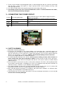
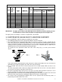
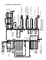
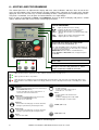
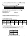
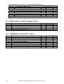
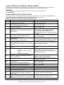
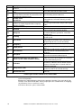
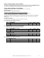
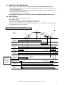
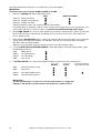
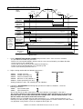
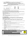
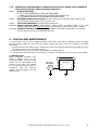
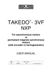
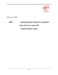
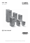
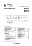
TAKEDO - 3VF NXS/NXP USER MANUAL 8 16-01-2007 REV. DATE R.T. Check and Approval CONTENTS 2 1 INTRODUCTION..................................................................................Page 3 2 SAFETY WARNINGS AND PRECAUTIONS .......................................Page 3 3 CONNECTING THE POWER CIRCUIT ..............................................Page 4 4 ENCODER : CONNECTION AND TYPES .........................................Page 6 5 APPLICATION EXAMPLE ...................................................................Page 7 6 KEYPAD AND PROGRAMMING .........................................................Page 8 7 ADJUSTMENT PROCEDURE .............................................................Page 16 8 CHECKS AND MAINTENANCE...........................................................Page 21 9 SUMMARY TABLE OF SASSI MOTOR PARAMETERS .....................Page 22 DECLARATION OF CONFORMITY.....................................................Page 23 TAKEDO - 3VF NXS/NXP USER MANUAL Release 8 date 16-01-2007 1 – INTRODUCTION The TAKEDO–3VF NXS/NXP is an inverter drive with built-in EMC filter and smoothing choke, responding to Council Directives 89/336/CEE (electromagnetic compatibility) 73/23/CEE (low voltage equipment). The drive can operate both in open loop mode (NXS) and in closed loop mode (NXP). For operation in closed loop mode, an optional circuit board is required, and a 5V line driver or 24V push-pull type encoder. This manual provides you with the necessary information about putting on duty and the operation of NXL frequency converter. You can find further information about application and installation in a lift control panel in the ANNEX NXS/NXP FOR PANEL WIRING SPECIALISTS, available in electronic edition on our website: www.sms.bo.it. 2 – SAFETY WARNINGS AND PRECAUTIONS Read this manual in its entirety before powering up the equipment, following the procedures step by step. In detail, please read carefully the Chapters: 7 – ADJUSTMENT PROCEDURE 6.4 – ACTIVE FAULTS 2.1 SAFETY WARNINGS Follow the procedures indicated below with due care, so as to avoid any risk of serious accidents. 1- Do not use an oscilloscope or other such instrument to test the internal circuits of the inverter. This type of operation must be performed only by a specialist technician. 2- The leakage current from the inverter to ground is greater than 30mA, and accordingly, the power circuit must incorporate a residual current device with Id no less than 300mA, type B or type A. Regulations require that the connection to ground be made with cable of not less than 10 mm² section. 3- If the parameters used in programming the drive are incorrect, the motor may be caused to rotate at a speed higher than synchronous. Do not run the motor beyond its specified electrical and mechanical limits. The installer is responsible for ensuring that movements are generated in conditions of safety, without exceeding specified operating limits. 4- Risk of electrocution. Power up the inverter only with the front cover fitted. NEVER remove the cover during operation. Before carrying out any operation on the equipment, isolate from the electrical power supply and wait a few minutes for the internal capacitors to discharge. 5- The external braking resistor heats up during operation. Do not install it close to or in contact with inflammable materials. To improve heat dissipation it is good practice to fix the resistor to a metal plate. Ensure it is properly protected and cannot be touched. 6- The inverter have to be always connected to the mains supply . In case of interruption wait 1 minute at least before restore supply . TOO NEAR INSERTIONS OF THE MAINS CAN CAUSE A PERMANENT DAMAGE OF THE INVERTER. 2.2 PRECAUTIONS Follow the procedures indicated in the manual with care so as to avoid the risk of damaging or destroying the drive. 1- Do not connect the equipment to a voltage higher than the permissible input voltage. An excessive voltage can cause irreparable damage to internal components. 2- To avoid the risk of damaging the drive in case it stays unworking without power supply for a long time, you should follow these precautions: - If the inverter doesn’t work since several months, before starting the operation, power up the drive at least for 1 hour preventing it can operate, so that the bus capacitors could regenerate themselves. - If the inverter doesn’t work since one year or more, to regenerate the bus capacitors power up the drive, preventing it can operate, for 1 hour at an input voltage less than 50% the rated voltage, then for 1 hour at the rated input voltage. 3- Do not connect capacitors to the inverter outputs. 4- If the drive protection functions trip, do not reset the fault before having analysed and removed the cause of the fault. TAKEDO - 3VF NXS/NXP USER MANUAL Release 8 date 16-01-2007 3 5- The lift system should be counterweighted at 50%, if counterweighted at 40% the current in up direction with full load is greater and requires a larger capacity inverter to that normally necessary, with consequent greater cost. 6- Use a drive having rated current equal to or greater than the motor rated current . 7- The braking resistor have to be connected between B+ and R- . If connected between B+ and B-, the inverter will be permanently damaged. 3 – CONNECTING THE POWER CIRCUIT L1;L2;L3 A.C. mains power input L1;L2 D.C. power input U;V;W Inverter output B+;R- External braking resistor Ground Connect the three phases of the power supply to any three terminals, in any order Connect the batteries in the event of emergency operation (evacuation) Connect the three output phases to the contactors, then to the motor Connect the external braking resistor Connect to the ground system CC terminals Braking resistor terminals Ground terminals Mains cable Motor cable 3.1 SAFETY WARNINGS 1- Ground the unit before powering it. 2- To increase the protection of the internal diodes and connecting wires (especially against the overvoltage due for example to atmospheric phenomena), you should connect three fast-acting fuses (one for each phase) in series with the a.c. power input terminals; fuses must be rated to match the different size designations as indicated in TABLE – Recommended braking resistors and fuses. The fuse kit, complete with box, is available on request. 3- To avoid irreparable damage to the inverter, do not connect braking resistors with resistance or power ratings lower than those indicated in TABLE. For long run lifts or high reverse gain gears, install the braking resistor with oversized power but with the same value in ohms (if needed, contact SMS for advices). 4- The inverter drive is connected <<up line>> of the power contactors. The drive is able to pilot operation of the motor in two directions, accordingly, the system can incorporate only two power contactors to switch the inverter – motor line, as prescribed by safety regulations. 5- The external braking resistor heats up during operation. Do not install it close to or in contact with inflammable materials. Ensure it is properly protected and cannot be touched. 6- Wire and bond ground connections in accordance with professional standards (as indicated under heading 3.2) to avoid problems with EMC interference. 7- Take particular care over the power connections. If the input and output connections are reversed, the inverter will be inevitably damaged. 4 TAKEDO - 3VF NXS/NXP USER MANUAL Release 8 date 16-01-2007 NOMINAL CURRENT (A) 3 8 4 5.5 10 13 NXS(P)0009 NXS(P)0012 NXS(P)0016 7.5 18 NXS(P)0022 11 15 24 32 NXS(P)0031 NXS(P)0038 18.5 42 22 30 48 61 37 75 FAST ACTING FUSESI (A) SIZE (kW) INVERTER 400 VOLT (380÷500V) SERIES VACON CODE DIMENSIONS LxWxH (mm) 128x292x190 25 128x292x190 144x391x214 BRAKING RESISTOR SUPPLIED BY SMS MINIMUM VALUE (Ω Ω) DIMENSIONS LxWxH (mm) 200x35x30 65Ω 350W 61Ω 25 65Ω 350W 61Ω 200x35x30 25 2x130Ω 350W 61Ω 144x391x214 55 50Ω 1500W 42Ω 200x35x30 (*) 445x110x140 144x391x214 195x519x237 55 80 50Ω 2x50Ω 1500W 1500W 42Ω 25Ω 445x110x140 445x110x140 (*) NXS(P)0045 195x519x237 110 2x50Ω 1500W 20Ω 445x110x140 (*) NXS(P)0061 NXS(P)0072 195x519x237 237x591x257 110 140 3x50Ω 5x50Ω 1500W 1500W 14Ω 6,1Ω 445x110x140 (*) 445x110x140 (*) NXS(P)0087 237x591x257 140 5x50Ω 1500W 6,1Ω 445x110x140 (*) (*) Full dimension is the one indicated multiplied by the number of resistors. TABLE 1 – Fuses and recommended braking resistors IMPORTANT: For high travel (>30m) or gear with high inverse efficiency, install the braking resistor recommended as value in ohm, but power corresponding to the next higher size. For higher powers and voltages, or advices on application, consult SMS. 3.2 INVERTER/MOTOR CABLING RULES TO ASSURE EMC CONFORMITY The correct INVERTER – MOTOR cabling must follow the rules below: 1- The building ground plant must be connected to both the inverter and motor. 2- The inverter/contactor and contactor/motor cable runs must be as short as possible, shielded with four poles (three phases plus yellow/green ground wire), or four unshielded wires bound together running in a duct or grounded metal tube. In other words, in the same cable or tube there must be a ground wire running as close as possible to the power cables. In the case of a shielded cable the shield must be unbroken between the inverter/contactor and contactor/motor . The shield have to be grounded at both ends with a 360° clamp (Fig. 1), or with special terminals (Fig. 2). FIG. 1 3- 456- FIG. 2 If the shield cannot be grounded with a 360° clamp on the motor terminal block itself, the shield must be grounded on the motor casing before the cable enters the terminal box. Use a shielded cable also for the inverter input power line to avoid radiated EMC emissions in the system. The mains input power cables and inverter output cables MUST NOT be run in the same duct and their runs must be as far apart as possible (at least 50 cm.). The power and control cables must be run as far apart as possible and not parallel to each other, even if they are shielded; if the cable runs cross they must do so at an angle of 90°. Independently of the connection to the building grounding plant, the motor casing MUST be connected both to the cable shield and to the yellow/green ground wire inside the shielded cable. The inverter emits electromagnetic radiation which can be captured and transmitted by cables, in particular by the flexible cables in the shaft. TAKEDO - 3VF NXS/NXP USER MANUAL Release 8 date 16-01-2007 5 To avoid this problem, use shielded cables for the control panel logic / inverter connections, with the shield grounded at both ends. DO NOT use shielded cables without grounding the shields: this leads to higher levels of EMC disturbance than if unshielded cables are used. Any wire in a multi-pole cable which is not in use must be grounded at both ends. 7- Any cable, whether control and external shaft or car connections, must never run parallel/near to the power cable, even if shielded; if they must be parallel for any reason, they should be run through separate metal ducts. 8- The pulse generator cable must be shielded and grounded only at the inverter end, as far as possible from the motor cable. Make sure that the shield is not grounded at the motor end using a tester on the shield/motor connection: if the shield is grounded at the motor end and this cannot be avoided, do not ground it at the inverter end. The motor/pulse generator coupling must be isolated to avoid parasitic currents looping through the pulse generator. As for all other shields, the ground connection must be via a 360° clamp. 9- All ground connections should be as short as possible and wide . (a) (b) Copper braid (a) is better than wire (b). 10- To avoid unintentional tripping of the differential circuit breakers take the following steps: − make the power cable runs as short as possible − use circuit breakers designed for harmonics (type B or type A, with tripping current 300mA). − reduce the inverter carrier frequency (if possible); lower frequency means greater motor noise, but smaller grounding currents and smaller EMC phenomena. 4 – ENCODER : CONNECTION AND TYPES Board NXOPTA4 or NXOPTA5 (optional), inserted in slot C (3° from left) When operating in closed-loop mode, the inverter drive requires a feedback signal provided by an industrial encoder , resolution 1024 pulse/rev (encoders specified within the range 300 - 5000 pulse/rev can also be used) , of type : Line driver powered at 5Vdc or Push-pull powered at 15 or 24 Vdc. SMS can supply a LIKA I581024H encoder, 1024 pulse/rev , that works with both NOXOPTA4 and NXOPTA5 boards , working in line driver mode if powered at 5Vdc , push-pull mode if powered at 15 or 24 Vdc. The encoder cable must be shielded, and the shield connected (as indicated in heading 5.2) to the inverter ground terminal. In any event, the encoder should have a shielded cable of length sufficient to allow connection direct to the inverter, following the shortest possible run and located well away from the power cables. TERMINAL SIGNAL LIKA I581024H ENCODER terminal 01 A+ YELLOW terminal 02 A- BLUE terminal 03 B+ GREEN terminal 04 B- ORANGE terminal 09 – Power supply BLACK terminal 10 + Power supply RED CAUTION! If the encoder used is not supplied by SMS , if it is LINE DRIVER type , the NXOPTA4 encoder board have to be used, whereas if a 15V or 24V PUSH-PULL type is installed, the NXOPTA5 encoder board will be needed. 6 TAKEDO–3VF NXS/NXP USER MANUAL Release 8 date 13-11-2006 Ke HS-HIGH SPEED TAKEDO–3VF NXS/NXP USER MANUAL Release 8 date 13-11-2006 B- B+ A- A+ SHIELDED CABLE + 5VDCLINE DRIVER 24VDC PUSH-PULL TP1 IMPORTANT: ENCODER BOARD IS NOT PRESENT IN OPEN LOOP VERSION TP Ke2 EMERGENCY OPERATION DOWN-DOWNWARD UP-UPWARD MS-INSPECTION SPEED LS-LOW SPEED 10 2 3 ENCODER BOARD NXOPTA4 4 (LIine driver) or 9 NXOPTA5 (Push-pull) 1 7(GND) 11(CMA) DO1 RO2 RO1 26 25 22 23 20 12 19 18 AC AC R- B+ W V U Ke2 SHIELDED CABLE EXTERNAL BRAKING RESISTOR GROUND CABLE TP1 CONTACTORS TP SHIELDED CABLE SHIELDED CABLE SHIELDED CABLE SHIELDED CABLE M 3-PH OPERATION VOLTAGE – TB BRAKE CONTACTOR Imax<400mA ; Vmax<=125 VDC OPERATION VOLTAGE + FAULT RELAY Imax<400mA ; Vmax<=125 VDC OPEN COLLECTOR OUTPUT I<50mA D.C. ; V=24 VDC Use as speed detector or as contactor de-energization control Programmable by param. 2.7.1 CONTACTOR CONTROL RELAY COIL 12V 20mA MAX To allow emergency operation, these terminals have to be connected to a supply voltage 220VAC (I>300mA). SHIELDED CABLE IMPORTANT: FILTER AND INDUCTANCE ARE MOUNTED INSIDE THE INVERTER ACCORDING TO THE EMC STANDARDS, YOU MUST USE SHIELDED CABLE AS INPUT AND OUTPUT CABLES (-) (+) EMERGENCY BOARD 102.06.NXEM1 TAKEDO 3VF NXS/NXP +24VDC I<250mA 17(CMB) 6 10 9 8 16 15 14 L3 T L1 L2 Ke SHIELDED CABLE Ke2 S R SHIELDED CABLE THREE PHASE LINE BATTERIY SUPPLY 48-96V 5 – EXAMPLE OF APPLICATION 7 6 – KEYPAD AND PROGRAMMING The control panel has an alphanumeric display with nine status indicators and three lines of text for the menu, the descriptions of the menu/submenu and the number of the submenu or the value of the function displayed. There are also nine keys used for controlling the drive, setting parameters and displaying values. The panel is removable, since all parts are isolated from the a.c. input voltage. Items of data are organized in menus and submenus, by way of which to display and process control signals, indicate faults and measurements and change parameters. STATUS INDICATORS RUN = lights up when the motor is running = indicates the direction of rotation selected STOP = lights up when the motor is at standstill READY = lights up when the drive is powered up and ready for use FAULT = lights up when a fault is detected in the drive ALARM = lights up when an alarm is tripped Position indication: displays the symbol and the number of the menu, the parameter, etc.. The symbol I/O term indicates that that the I/O terminals are the selected control interface; in other words, the commands are given via the I/O terminals IMPORTANT: When the drive is used with lift motors, neither Keypad nor Bus/Comm must ever appear in place of I/O term FIG. 4 – Control panel with Liquid Crystal Display Description line: displays the description of the menu, value or fault. Values line: indicates the numerical value and descriptor of reference data, parameters etc. and the number of submenus available in each menu. Lights up when power is supplied to the drive. Indicates that the inverter is ready for use. Lights up when the drive is in operation. Lights up when risk conditions have been identified and caused the drive to shut off (lock-up caused by fault). At the same time, the FAULT status indicator blinks in the display, which also shows a description of the fault; see Heading 7.3.4, Active Faults. Menu left Explore menu back. Moves the cursor to the left (in the PARAMETERS menu). Used to quit edit mode. Press and hold for 2…3 seconds to return to the main menu. Menu right Explore menu forward. Moves the cursor to the right (in the PARAMETERS menu). Used to access edit mode. Up arrow Scroll main menu and pages of various submenus. Changes a parameter by increasing the value. enter select Enter: Confirm selection. Used to reset faults memory: press and hold for 2…3 seconds Select Toggles between the last two items displayed. Useful for verifying how a newly edited value will impact on another value. START START (NOT used) STOP STOP (NOT used) Down arrow Scroll main menu and pages of various submenus. Changes a parameter by decreasing the value. reset Reset Resets active faults. FIG. 5 – Control keypad 8 TAKEDO–3VF NXS/NXP USER MANUAL Release 8 date 13-11-2006 The submenus are accessible from the main menu using the key. The symbol M on the first text line indicates the main menu. It is followed by a number that refers to the submenu in question. The arrow (→ →) at the bottom right of the display indicates a further submenu that can be recalled by pressing the key. To go back to the main menu from the submenu, simply press the key. Data are divided into Menus and Submenus. The main menus are organized on seven levels M1-M7. To go from one menu to the next, use the increase/decrease keys or . M1=Visualizzazione / Monitor M5=Storico guasti / Fault history M2=Parametri / Parameters M6=Menu di sistema / System menu M3=Controllo tastiera / Keypad control M7=Schede espansione / Expander boards M4=Guasti attivi / Active faults Each menu contains submenus, which can also be on several levels. To access the submenus, press the key, then use the +/- keys to show the various quantities; to quit the submenu, press the key. KEY TO SYMBOLS CONTAINED IN MENUS AND SUBMENUS: M= menu (internal modes G,V,P,H,F) G= group (internal modes V,P) V= read only H= historical fault P= modifiable parameter F= active fault 6.0 – COPY OF PARAMETERS WITH KEYPAD Programming keypad can also be used to copy parameters to or from the inverter. This function could be very useful when is needed to transfer the optimal parameter set found for a lift on another lift of the same type. 6.0.1 – COPY FROM INVERTER TO KEYPAD Push the left arrow key until the ‘M’ letter , followed by the menu number (e.g. M2) , is not appeared on the left high corner of the display . Push up or down arrow key to reach M6. M6 S6.3 S6.3.2 System Menù Copy Parameters Up to keypad S1>S8 → Pushing the right arrow key will be displayed S6.1.Push the up arrow key to reach S6.3. P1>P4 → Select → Pushing the right arrow key will be displayed S6.3.1.Push the up arrow key to reach S6.3.2. Push the right arrow key. S6.3.2 Up to keypad S6.3.2 S6.3.2 Up to keypad Up to keypad All param. Push Enter to start data copy. Wait… Wait the end of the copy. OK Copy done . Keypad contains the inverter data. 6.0.2 – COPY FROM KEYPAD TO INVERTER Selecting S6.3.3 , will be displayed “Down from keypad” . Proceed in the same way described before. Note : During the copy from keypad to inverter some data copy will appear as “Locked” . This happens because there are fixed parameters that are not modifiable (reserved) . Pushing Enter key any time “Locked” appears (about 6-7 times) copy proceeds and “Ok” will be displayed. Attention : Copy from a keypad when its data comes from an inverter of the same size of the one you are copying into. Connecting the keypad to the inverter in which you want to copy the data , it will appear : Copy To Panel? enter/reset Push RESET because you want to copy the keypad data into the inverter. Copy From Panel? enter/reset Push ENTER to start the copy and wait . TAKEDO–3VF NXS/NXP USER MANUAL Release 8 date 13-11-2006 9 6.1 M1 = MONITOR The caption V1→ →V19 appears under the menu. This means there are 19 quantities that can be monitored. CODE SIGNAL NAME CODE SIGNAL NAME V1.1 V1.2 Frequenza uscita / Output frequency Rif. Frequenza / FreqReference V1.13 V1.14 V1.3 Velocità motore / Motor Speed V1.15 V1.4 Coppia motore / Motor Torque V1.16 V1.5 V1.6 V1.7 V1.8 V1.9 V1.10 V1.11 Potenza motore / Motor Power Corrente motore / Motor Current Tensione motore / Motor Voltage Tensione bus C.C. / DC-link Voltage Temperatura inverter / Unit temperature DIN1, DIN2, DIN3 (Up, Down, Evac) DIN4, DIN5, DIN6 (High, Low, Inspection) V1.17 V1.18 V1.19 V1.20 Uscita analogica / Analog Iout (Not used) Velocità cabina / Lift Speed Giri Enc_Rallent / Enc Rev_Half floor (High speed Low speed) Giri Enc_Stop / Enc Rev_Stop (Low speed Brake) Vel. Encoder / Encoder Freq (Hz) Dist Rall_Stop / Half Floor Dist (mm) Dist Stop_Piano / Stop Distance (mm) Memoria Cont Antic / Advan Cont Memory V1.12 DO1, R01, R02 (Programmable output: Contactors, Fault, Brake) 6.2 M2 = PARAMETRI / PARAMETERS The caption G1→ →G11 appears under the menu. Selecting the menu, the following groups can be displayed: IMPORTANT Parameters which have GRAY background MUST NOT be modified. G2.1 PARAMETRI BASE / BASIC PARAMETERS P1→ →P7 Par. P2.1.1 P2.1.2 P2.1.3 P2.1.4 P2.1.5 P2.1.6 P2.1.7 P2.1.8 P2.1.9 P2.1.10 Description Limite corrente / Current Limit Tensione Nom Motor / Motor Nom Voltag Frequen Nom Motore / Motor Nom Freq Velocità Nom Motor / Motor Nom Speed Corrente Nom Motor / Motor Nom Currnt Cos fi Motore / Motor Cos Phi Tipo Motore (SASSI) / Motor Type Default Identificazione / Identification Controllo Ventilatore / Fan Control Password Mod Par / Par Edit Password Unit A V Hz rpm A Default 1.8 x Inv 380 50 1440 Inv 0.82 Value 0 / None 0 / No Action 1/Marcia 0 G2.2 CONFIGURAZIONE CORSA / RUN CONFIGURATION P1→ →G21 Par. P2.2.1 P2.2.2 P2.2.3 P2.2.4 P2.2.5 P2.2.6 P2.2.7 P2.2.8 P2.2.9 P2.2.10 P2.2.11 P2.2.12 P2.2.13 P2.2.14 P2.2.15 P2.2.16 P2.2.17 P2.2.18 P2.2.19 P2.2.20 10 Description Frequenza Massima / Max Frequency Vel lineare nom / Nominal Linear Speed Rampa Acceleraz / Acceleration Rampa Deceleraz / Deceleration Rampa Decel Finale / Final Decelerat v0 000 zero / zero v1 100 alta / high v2 010 bassa / low v3 110 alta+bass / high+low v4 001 ispezione / inspect. v5 101 alta+isp / high+insp v6 011 bassa+isp / low+insp v7 111al+ba+isp / hi+lo+ins Arrot Inizio Accel / Acc Inc Jerk Arrot Fine Acceler / Acc Dec Jerk Arrot Inizio Decel / Dec Inc Jerk Arrot Fine Decel / Dec Dec Jerk Rilev Auto Dist / Auto Half Dist Dist Rall_Stop / Half Floor Dist Interp Min Freq / Half Floor Freq Unit Hz m/s s s s Hz Hz Hz Hz Hz Hz Hz Hz s s s s mm Hz TAKEDO–3VF NXS/NXP USER MANUAL Release 8 date 13-11-2006 Default 50 1.00 2.5 2 0.5 0 50 5 0 25 0 0 0 2 0.6 0.6 1.2 0 1000 25 Value G2.2.21 Anello Chiuso / Closed Loop P1→P6 (solo NXP / NXP only) Par Descrizione u.d.m P2.2.21.1 Pre-avv. tempo / SmoothStart Time s P2.2.21.2 Pre-avv. freq / SmoothStart Freq Hz P2.2.21.3 Rampa Acc Iniziale / Initial Acceler. s P2.2.21.4 Tempo 0Hz Start / 0Hz TimeAtStart s P2.2.21.5 Tempo 0Hz Stop / 0Hz TimeAtStop s P2.2.21.6 Distanza stop / Stop distance mm Def 0.0 0.3 0.5 0.7 0.4 0 Valore Unit % s A s s Hz Default 10 0.3 0.7 Iinv 0.0 0.4 1,5 Value Unit Default 0 0 0.2 0.5 0.3 0.3 Value Default 10 0 0 0.5 0.3 Value Default 0.5 0.15 Value Default Value G2.3 CONTR. FRENATURA/BRAKE CONTROL P1→ →G7 G2.3.1 Anello Aperto / Open Loop Par Description P2.3.1.1 Corrente Min Apert / Min Curr Brake Open P2.3.1.2 Ritar.Chius Freno / Brake Close Delay P2.3.1.3 Corrente FrenatCC / DC-Brake Current P2.3.1.4 Tempo FrCC Start / Start DC-brake Tm P2.3.1.5 Tempo FrCC Arresto / Stop DC-Brake Tm P2.3.1.6 Freq FrCC arresto / Stop DC-Brake Fr G2.3.1.7 Funz. Avanzate / Advanced Funct. P1→ →P6 Par Description P2.3.1.7.1 Riservato / Reserved P2.3.1.7.2 Freq Minima Apert / Min Freq Brake Open P2.3.1.7.3 Ritar.Apert Freno / Brake Open Delay P2.3.1.7.4 Freq Minima Chius / Min Fre Brake Close P2.3.1.7.5 Pre-avv. freq/SmoothStartFreq P2.3.1.7.6 Pre-avv. tempo /SmoothStartTime G2.3.2 Anello Chiuso / Closed Loop P1→G6 (solo NXP / NXP only) Par Description P2.3.2.1 Corrente Min Apert / Min Curr Brake Open P2.3.2.2 Riservato / Reserved P2.3.2.3 Freq Minima Apert / Min Freq Brake Open P2.3.2.4 Freq Minima Chius / Min Freq Brake Close P2.3.2.5 Ritar.ChiusFreno / Brake Close Delay Hz s Hz Hz s Unit % Hz Hz s G2.3.2.6 Funz. Avanzate / Advanced Funct P1→P2 (solo NXP / NXP only) Par Description Unit P2.3.2.6.1 Ritar Apert Freno/Brake Open Delay s P2.3.2.6.2 Freq Max Fren Chius / MaxFreq If Close Hz G2.5 CONTROLLO MOTORE / MOTOR CONTROL P1→ →G4 Par P2.5.1 P2.5.2 Description Stato Contr Motore / Motor Ctrl Mode Freq Commutazione / Switching Freq G2.5.3 Anello Aperto / Open Loop P1→ →G7 Par Description P2.5.3.1 Ottimizzaz V/f / V/f Optimization P2.5.3.2 Sel Rapporto V/f / V/f Ratio Select P2.5.3.3 V/f Freq Intermedia / V/f Mid Freq P2.5.3.4 V/f Tens Intermedia / V/f Mid Voltg P2.5.3.5 Tensione A Freq 0 / Zero Freq Voltg G2.5.3.7 Funz. Avanzate 1 / Advanced Funct 1 P1→ →P6 Par Description P2.5.3.7.1 Contr Veloc Kp / Speed Control Kp P2.5.3.7.2 Contr Veloc Ki / Speed Control Ki P2.5.3.7.3 FreqSwitchBasVel / LowSp.SwitchFreq P2.5.3.7.4 Soglia BasVel / LowSp. Level P2.5.3.7.5 Caduta Tens RS / RS Voltage Drop P2.5.3.7.6 Corrente a 0Hz / Current at 0Hz Unit 1/OpenLoop kHz Unit 10 Default Value 1/Automatic boost 2/Programmable Hz % % 1.75 5.0 3.5 Unit Default 3000 300 6 5 kHz Hz Value Different from 0, depends on the size % TAKEDO–3VF NXS/NXP USER MANUAL Release 8 date 13-11-2006 50 11 G2.5.4 Anello chiuso / Closed loop P1→G9 (solo NXP / NXP only) Par Descrizione u.d.m. Def. P2.5.4.1 Corrente Magnetiz / Magn Current A 0.5Iinv P2.5.4.2 Lim 1 Adattativo/Adaptive Lim 1 Hz 0.1 P2.5.4.3 Lim 2 Adattativo/Adaptive Lim 2 Hz 0.5 P2.5.4.4 Contr Veloc Kp1/Speed Cntrl Kp 1 40 P2.5.4.5 Contr Veloc Ti1/Speed Cntrl Ti 1 ms 40 P2.5.4.6 ContrVelocKp2/Speed Cntrl Kp 2 20 P2.5.4.7 Contr Veloc Ti2/Speed Cntrl Ti 2 ms 40 P2.5.4.8 Tempo Filtro Encdr1 / Encoder1 Filt Time ms 0 NOTE : With 2.5.4.8 equal to 0, parameter 7.3.1.3 must be equal to 5 ms Valore G2.7 SEGNALI USCITA / OUTPUT SIGNALS P1→ →G7 Par. P2.7.1 P2.7.2 P2.7.3 P2.7.4 P2.7.5 Description Config uscitaD01 / D01 Content Inversione D01 / D01 Inversion Ritardo D01 / D01 Delay LimiteVerif Freq / Freq Superv Limit ValoreVerif Freq / Freq Superv Value Unit Default Value 15 / Motor Switch 0 / Off s 0 1 / Low Limit Hz 30 G2.10 EMERGENZA / EVACUATION P1→ →G10 Par. P2.10.1 P2.10.2 P2.10.3 P2.10.4 P2.10.5 P2.10.6 P2.10.7 P2.10.8 P2.10.9 12 Description Modo Emergenza / Evacuation Mode Input Attiv Emerg. / Evacuation Input Max Vel Emergenza /Max Speed In Eva Ottimizzaz V/f / V /f Optimization V/f Freq Intermedia / V/f Mid Freq V/f Tens Intermedia / V/f Mid Voltg Tensione a Freq0 / Zero Freq Voltg Corrente Magnetiz / Magn Current Freq Commutazione / Switching Freq Unit Default 2 / Automatic DigIN:A.3 Hz 5 1 / AutoTorq Boos Hz % % A klH TAKEDO–3VF NXS/NXP USER MANUAL Release 8 date 13-11-2006 1.75 5.0 3.5 0.5xInv 3 Value 6.3 M3 = CONTROLLO TASTIERA / KEYPAD CONTROL The caption P1→P4 appears under the menu. This means there are 4 quantities that can be changed. Internally of this function, it is possible to define how commands are given to the inverter. IMPORTANT These parameters must not be changed, otherwise the inverter drive will not operate. 3.1 = I/O terminal. 6.4 M4 = GUASTI ATTIVI / ACTIVE FAULTS Listed below are the most common fault messages. Be careful not to reset the alarm or fault without first having investigated the problems that caused the protection mechanism to cut in. Always deselect the run command before resetting any fault. Code 1 2 5 Description Overcurrent: current 4 times the nominal value detected at the inverter output Overvoltage: detection of DC link voltage too high Charge switch: The charge switch is open when the drive is in running. Cures / Indications Check the condition of cables and motor, also the size of the inverter drive Increase the deceleration time, check the value of the braking resistor. Reset the fault and restart . If the fault happens again , contact SMS. Cannot be reset from the keypad. Switch off power. DO NOT RE-CONNECT POWER! Contact factory. If this fault appears simultaneously with Fault 1, check motor cables and motor. 7 IGBT Temp : One or more power component malfunctioning. 8 System fault : - Damaged or malfunctioning component. - Verify data register 7.3.4.3 Reset the fault and restart . If the fault happens again , contact SMS. 9 Undervoltage: detection of DC link voltage too low. Check that the voltage input to the inverter drive is correct and steady. If the fault occurs during acceleration, increase the acceleration time. 3 10 11 63 Power stage faults : detection of fault in power Check the power cables on the input/output sides connections (input or output phase missing, earth and/or the motor insulation . fault, etc) 12 13 14 16 15 17 22 23 25 26 32 36 37 38 Braking fault: fault affecting braking resistor or chopper Temperature inverter drive undertemperature; (-10°C) inverter drive overtemperature; (+90°C) motor overtemperature Motor stall: the motor has not started while the inverter has already reached 90% of the limit current settled in 2.1.1 Motor underload EEPROM “Checksum” error : Parameter recovery failed -Damaged or malfunctioning component Microprocessor watch-dog error : -Damaged or malfunctioning component Start up prevented Fan cooler not working Control unit fault : NXS control unit can’t drive power unit NXP and vice-versa. Device changed : Option board or control unit changed. Same type of board or same power rating of drive. Device added : Option board or drive added. Drive of same power rating or same type of board added. Check the connection and/or the size of the resistor . Make certain the air flow around the drive is sufficient to cool the heat sink and/or check for possible motor overload. Check the brake or the counterweight if the stall happens in down run without load. Make certain the motor is not too small for the rated power of the drive. Reset the fault and restart . If the fault happens again , contact SMS. Reset the fault and restart . If the fault happens again , contact SMS. Cancel prevention of start-up. Contact SMS. Change the control unit. Reset Note: No fault time data record! Reset Note: No fault time data record! TAKEDO–3VF NXS/NXP USER MANUAL Release 8 date 13-11-2006 13 Code 39 40 41 43 56 Description Device removed : Option board removed. Drive removed. Device unknown : Unknown option board or drive. IGBT temperature : IGBT Inverter Bridge overtemperature protection has detected a short term too high overload current. Reset Note: No fault time data record! Reset Note: No fault time data record! Check loading. Check motor size. Channels inverted (invert parameter 7.3.1.2), connection loss or made incorrectly, or faulty encoder. Encoder alarm Speed Error 54 Keypad communication fault : The connection between the control keypad and the frequency converter is broken. Slot fault : Defective option board or slot. 57 Overload 59 Wrong run 60 Levelling 61 Low current 62 Emergency 63 Output phases 64 Low reference 67 Overspeed 68 Anticipated opening of the contactors (Please see the “Alarm 68 NOTE” below) 69 No Enable 70 Wrong license code 71 Identification error 52 Cures / Indications Check keypad connection and possible keypad cable. Check board and slot. Contact SMS. Motor limit torque exceeded . Verify the working current and the correct brake opening. The run direction has been inserted for more than 5 seconds without a speed level . Check the control panel. Low speed input falls before motor has reached the low speed. The inverter doesn’t open the brake because current doesn’t reach the value settled in 2.3.1.1 for open loop or in 2.3.2.1 for closed loop. Emergency input signal fall during the emergency run. Missing current in one or more output phases at start. The active speed level has a frequency reference and below the DC electrical braking start frequency. The inverter , due to some malfunctioning, exceeds the maximum allowed speed. The contactors between the inverter and the motor have been opened before the end of the electrical DC braking current. It can occur only If you use the ENABLE input (terminal 2), indicates that the Enable input has not been activated within 2 seconds from the contactor command. After the SMS application software download , the license code is not entered correctly. The identification of the motor was not terminated correctly. If other types of faults should occur, contact SMS. Alarm 68 NOTE After 20 trips of this alarm, the drive goes out of service and you need to use RESET key to resume the operation. Eliminate the malfunctioning by delaying the contactors opening. If you can’t do this (for example, in lifts with manual doors, where people opens the car door while car stopping), set parameters P2.3.1.5 and P2.3.1.2 to 0. If the alarm still occurs, please contact SMS. 14 TAKEDO–3VF NXS/NXP USER MANUAL Release 8 date 13-11-2006 6.5 M5 = STORICO GUASTI / FAULT HISTORY The caption H1→Hx appears under the menu. This indicates how many faults are memorized. Up to 30 faults can be memorized and displayed chronologically in reverse order (most recent fault displayed first). To reset faults, the (ENTER) key must be pressed and held for at least 3 seconds. enter 6.6 M6 = MENU DI SISTEMA / SYSTEM MENU The caption S1→S8 appears under the menu. This means there are 8 submenus. Language setting : S6.1 = language ITALIAN-ENGLISH-FRANCAIS SMS advises against modifying other parameters relative to this MENU. Should the need arise, contact SMS or use the original manual (www.vacon.com). 6.7 M7 = SCHEDE ESPANSIONE / EXPANDER BOARDS The caption G1→G5 appears under the menu. This means there can be up to 5 submenus. The number of submenus depends on the number of optional circuit boards connected. In this instance there will be no more than 3. G7.1 NXOPTA1 G1→ →G2 SMS advises against modifying the parameters relative to this submenu. G7.2 NXOPTA2 G1→ →G1 (digital relay outputs) G7.2.1 I/O monitor V1→ →V2 Par. Description V7.2.1.1 DigOUT:B1 (Digital output B.1) V7.2.1.2 DigOUT:B2 (Digital output B.2) Unit Default 1 0 Value Unit Value ms Default 1024 No 5 Unit Hz rpm Default x x Value Unit Default 1 0 0 Value G7.3 NXOPTA4 G1→ →G2 (5V line driver encoder board) or NXOPTA5 G1→ →G2 (24V push-pull encoder board) G7.3.1 Parametri / Parameters P1→ →P3 Par. Description P7.3.1.1 Pulse/revolution (Number of encoder pulses) P7.3.1.2 Invert direction (Encoder direction) P7.3.1.3 Reading rate (Encoder sampling) G7.3.2 Monitor V1→ →V2 Par. Description V7.3.2.1 Encoder frequency V7.3.2.2 Encoder speed G7.3 NXOPTB5 G1→ →G1 (digital relay outputs) G7.3.1 MONITOR I/O V1→ →V3 Par. Description V7.3.1.1 DigOUT:D1 (Digital output D.1) V7.3.1.2 DigOUT:D2 (Digital output D.2) V7.3.1.3 DigOUT:D3 (Digital output D.3) TAKEDO–3VF NXS/NXP USER MANUAL Release 8 date 13-11-2006 15 7 – ADJUSTMENT PROCEDURE IMPORTANT It is necessary to know the characteristics of the motor, normally indicated on dataplate, before proceeding to modify parameters. If you are using a SASSI motor and your kind of motor is present in the SUMMARY TABLE OF SASSI MOTORS (see CHAPTER 9 of this manual), you have only to set the parameter P2.1.7 “Motor type” and the data of the motor will be automatically settled inside the drive. If the motor is not present on the table , you have to set these parameters : NOMINAL VOLTAGE, NOMINAL FREQUENCY, NOMINAL SPEED, NOMINAL CURRENT, COS φ , inside the Basic Parameters of the drive. MAGNETISING CURRENT (P2.5.4.1) inside the Motor Control Group, if you are using a NXP closed loop drive. If these parameters aren’t programmed correctly , the drive won’t work correctly. Before starting to change any parameter or regulation, proceed in this way : 7.1 – SET THE DATAPLATE OF THE MOTOR INTO PARAMETERS P2.1.2/3/4/5/6/7. If the motor speed is not known, or if the nominal value on data plate is 1500 rpm: - if the motor is 1 or 2 speed, or for conventional ACVV regulator, set 1350/1380 rpm - if it is for a VVVF speed regulator, set 1440 rpm. If the cos phii value is not known: - if the motor is 1 or 2 speed, or for conventional ACVV regulator, set 0,76 - if it is for a VVVF speed regulator, set 0,80. 7.2 – PLACE THE DECELERATION COMMANDS AT A DISTANCE FROM FLOOR AS INDICATED IN THE TABLE (GREATER THE DISTANCE, MORE SMOOTHLY THE LIFT SYSTEM WILL OPERATE) DECELERATION DISTANCE TABLE Nominal lift speed (m/s) 0.6 - 0.8 1.0 1.2 1.4 1.6 1.8 2.0 1000 1400 1700 2000 2200 2600 2800 Deceleration distances (mm) In addition, position the stop switch centrally with respect to the floor. The STOPPING DISTANCE TABLE shows guideline values to consider in order to define activation distance of the stop switch (or switches): STOP MAGNET STOPPING DISTANCE TABLE = = D FLOOR LEVEL System nominal speed (m/s) 0.6 – 0.8 1.0 1.2 60 80 100 Total stopping distance (D) (mm) The stopping adjustment is performed using the inverter parameters (see the nex points 7.9 – 5 and 7.10 – 5). 7.3 – SET THE EXACT VALUES OF MAXIMUM FREQUENCY P2.2.1 (CORRESPONDING TO THE NOMINAL LIFT SPEED) AND HIGH SPEED P2.2.2. 7.4 – ADJUST THE INSPECTION FREQUENCY P2.2.10 TO OBTAIN A CAR SPEED LOWER THAN 0,63 m/s. 7.5 – SET THE MOTOR CONTROL TYPE : V/F FREQUENCY CONTROL OR OPEN LOOP FOR NXS, CLOSED LOOP FOR NXP. 7.6 – PAY ATTENTION: ALWAYS VERIFY THAT PARAMETERS P2.2.1 E P2.2.7 ÷ P2.2.10 ARE PROGRAMMED WITH FREQUENCIES COMPATIBLE WITH THE MOTOR RATED FREQUENCY. For example it is possible to find motors working at 30Hz, 38Hz, 45Hz, 55Hz, 60Hz, etc., mounted on gears. 16 TAKEDO–3VF NXS/NXP USER MANUAL Release 8 date 13-11-2006 7.7 – IDENTIFICATION (IMPORTANT!) After setting the correct motor data, it is essential to perform the IDENTIFICATION routine. - Set parameter P2.1.8 to 1 and transmit a call command: the contactors energizes, the brake doesn’t open, and “RUN” lights on. - When “RUN” lights off and “STOP” appears, the parameter P2.1.8 goes to 0, so deactivate the call (e.g. by opening the operation valve) - The boost parameters are now optimized. If you modify any motor data, it is essential to perform the IDENTIFICATION routine again. 7.8 – FAN CONTROL Set parameter P2.1.9 (fan control) as desired: 0 = continuous duty. 1 = the fan runs during run and for 1 further minute after the stop. 2 = the fan starts only when the drive temperature reaches 45°C. SMS advices not to modify the fan operation from default value (1), in order to assure a good cooling of the power part at each run of the lift.. 7.9 – OPEN LOOP ADJUSTMENTS 2.2.4 SPEED PROFILE 2.2.14 2.2.3 2.2.17 2.2.16 2.2.15 2.3.1.6 2.2.5 2.2.7 2.2.8 2.3.1.7.5 2.3.1.3 HIGH SPEED COMMAND HS LOW SPEED COMMAND LS RUN COMMAND 0,4s DC BRAKE TIME AT START 2.3.1.4 DC BRAKING CURRENT DC BRAKE TIME AT STOP 2.3.1.5 0,3s MOTOR CONTACTORS Matched the parameters 2.3.1.1 and 2.3.1.7.2 the brake open delay starts. SMOOTH START TIME 2.3.1.7.6 SMOOTH START FREQUENCY MECHANICAL BRAKE CONTROL DELAY BRAKE OPENING DELAY AT START 2.3.1.7.3 BRAK CLOSING DELAY AT STOP 2.3.1.2 BRAKE CONTROL RELAY (term. 25-26) MECHANICAL BRAKE BRAKE OPENING MECHANICAL DELAY TAKEDO–3VF NXS/NXP USER MANUAL Release 8 date 13-11-2006 BRAKE CLOSING MECHANICAL DELAY 17 After done what indicated at points 7.1/2/3/4/5/6/7/8 , proceed as follows: IMPORTANT Parameters have to be changed ALWAYS ONCE AT A TIME. 1 - Adjust the starting with brake control parameters JERK BACK ROTATION 2.3.1.7.3 Brake open delay 2.3.1.7.5 Smooth start frequency 2.3.1.7.6 Smooth start time Starting comfort has to be ‘soft’, without jerks nor back rotations. - If an higher torque at starting is needed, set the starting current at 0Hz in P2.5.3.7.6 (default=50%) to a greater value (do not set a value over 60%) and perform the IDENTIFICATION routine again. 2 - During high speed run , the rpm of the motor have to reach the required value, and the speed of the lift has to be constant. If not constant (oscillating) increase or decrease the value of the parameter P2.1.4. (Motor speed). 3 - Adjust now the deceleration phase . Lift has to reach the floor running for a short space at constant speed (10cm max.) without oscillations nor vibrations, with the same speed for both up and down directions and in any load condition. Adjust the space travelled at low speed with parameter 2.2.4 (Deceleration ramp). 4 - If, at the end of the deceleration the following parameters: 2.1.4 Motor Speed 2.5.3.3 V/F mid frequency 2.5.3.4 V/F mid voltage 2.2.8 Low speed 5 - If, at phase, motor stops hardly reaching the floor position, adjust floor arrival, car is not perfectly aligned at floor, the parameters to be adjusted are : If car stops BEFORE 2.2.5 2.2.8 2.3.1.3 2.3.1.6 If car stops AFTER Final deceleration at stop Low speed DC motor braking current Stop DC braking current IMPORTANT For low speed frequency a value of 1/10 of the rated frequency is suggested: Example – low speed set at 5Hz if motor rated frequency is equal to 50 Hz. 18 TAKEDO–3VF NXS/NXP USER MANUAL Release 8 date 13-11-2006 If position is different with or without LOAD - 7.10 – CLOSED LOOP ADJUSTMENTS 2.2.4 SPEED PROFILE 2.2.15 2.2.14 2.2.21.3 2.2.3 2.2.16 2.2.17 2.2.7 2.2.5 2.3.2.4 2.2.8 2.2.21.2 HIGH SPEED COMMAND HS LOW SPEED COMMAND LS RUN COMMAND TIME AT START 2.2.21.4 TORQUE LOCKED MOTOR COPPIA 0,4s TIME AT STOP 2.2.21.5 0,4s MOTOR CONTACTORS Matched the parameter 2.3.2.1 the brake open delay starts. SMOOTH START TIME 2.2.21.1 SMOOTH START FREQUENCY BRAKE COMMAND DELAY BRAKE OPENING DELAY AT START 2.3.2.6.1 BRAKE CLOSING DELAY AT STOP 2.3.2.5 BRAKE COMMAND RELAY (term.25-26) MECHANICAL BRAKE BRAKE CLOSING MECHANICAL DELAY BRAKE OPENING MECHANICAL DELAY 1 - Set the magnetising motor current with parameter 2.5.4.1: if this current is unknown, it is possible to find it with this procedure : - Balance the car load with weights until to reach the same current for both up and down direction - Set the inverter in V/F control mode - Set the high speed level to 2/3 of the motor rated frequency - Read the current absorbed during run at constant speed - Set the value found in parameter 2.5.4.1 2 - Adjust starting comfort with the following parameters : JERK 2.2.21.1 Smooth start time 2.2.21.2 Smooth start frequency 2.2.21.3 Initial acceleration ramp 2.2.21.4 0Hz time at start (about 0,7”) 2.3.2.6.1 Brake open delay (min. 0,5”) Starting comfort has to be ‘soft’, without jerks nor vibrations. BACK ROTATION 3 - If during the acceleration and during high speed travel motor has vibrations , check the following parameters : 2.5.4.6 Speed control KP2 2.5.4.7 Speed Control TI2 Check also that the encoder connections match the indications in paragraphs 3.2.8 and 4. The encoder cable have to be separated from the power cable and distant 50 cm at least from the motor cable . It have to be connected with a unique cable , without added terminals , and with the shield connected to earth from inverter side. Encoder pulses per revolution have to match parameter 7.3.1.1 . Verify also the parameter 7.3.1.3 normally set at 5ms by SMS . A good mechanical coupling between encoder and the fast motor shaft is very important: verify also the screws, the alignment of the joint, etc. TAKEDO–3VF NXS/NXP USER MANUAL Release 8 date 13-11-2006 19 4 - Verify the slowing phase. Lift has to reach floor in a very small space (few centimetres) , at constant speed without oscillations nor vibrations, both for up and down direction. Adjust the space travelled at low speed with parameter 2.2.4 (Deceleration ramp). IMPORTANT: Considering the high precision of the inverter , it is important to set the position of the slowing command with the best possible accuracy , to have the same space travelled at low speed for any floor. 5 - If, at floor arrival, the car is not perfectly aligned at floor, even if the stop switches are centred to the floor, the parameters to be adjusted are : It stops BEFORE 2.2.5 2.2.8 It stops AFTER Final deceleration ramp Low speed level A very good comfort can be obtained (for a 50 Hz rated frequency lift motor) with a 3Hz low speed and a 0,8 seconds final deceleration. 7.11 – ONE FLOOR TRAVEL (for both open and closed loop) When the desired starting and stopping comfort has reached and, running between far floors, the space travelled at low speed is the same for any floor for both up and down direction, you have to set the slowing distance, especially useful for one floor travel, with parameter P2.2.19 as follows: - Set parameter P2.2.18 to 1. - Make a car call for 2 floors at least. - When lift will reach low speed, P2.2.18 will return automatically to 0 , while the distance travelled will be set into P2.2.19. - Make a car call for one floor only, verify comfort, and check that the space travelled at low speed is the same as a travel between far floors . To increase comfort further, decrease parameter P2.2.20 (Half floor frequency). 7.12 – MOTOR NOISE In case of motor noise , increase switching frequency P2.5.2, considering that higher is the frequency, higher are EMC emissions. In addition, the motor insulation and the inverter power components are more “stressed”. 7.13 – ALARMS THAT MAY APPEAR DURING THE SYSTEM SETUP PHASE 43 = Encoder: Encoder is damaged, not properly connected or it runs in opposite direction. For this last case modify parameter 7.3.1.3 from NO to YES. 56 = Speed error: Real speed is different from settled speed. Check the magnetising current and eventually increase 0Hz start time (P2.2.21.4) and brake open delay (P2.3.2.6.1). 59 = Run Error: Up/Down run command is active, but there is none speed level. 60 = Levelling: Lift stops at floor when low speed is not yet reached , that means during the deceleration . In this case decrease deceleration time P2.2.4. 02 = Overvoltage: DC link voltage exceeded the limit. Check the connection of the braking resistor and its value in according to the table at page 5.If necessary, increase the slowing distance. 61 = Low current: Brake doesn’t open because the motor current is too low (modify P2.3.1.1=minimum current for brake opening). 63 = Output phase: Missing current in one phase during start. 64 = Low reference: Check speed level parameters and command signal cabling. 68= ANTICIPATED OPENING OF THE CONTACTORS: The contactors between inverter and motor have been opened during the DC current injection at stop. A repeated intervention of this alarm can permanently damage the inverter and decreases significantly the contactors lifetime. 20 TAKEDO–3VF NXS/NXP USER MANUAL Release 8 date 13-11-2006 7.14 – PARAMETERS FOR EMERGENCY OPERATION WITH BATTERY POWER SUPPLY(MINIMUM 48VDC) EFFECTIVE ONLY FOR EVACUATION PURPOSES. 2.10.1 EVACUATION MODE: 0 = NOT USED (EMERGENCY FEATURE EXCLUDED) 1 = MANUAL (DOES NOT SELECT FAVOURABLE RUN DIRECTION) 2 = AUTOMATIC (SELECTS FAVOURABLE RUN DIRECTION) 2.10.3 MAXIMUM SPEED IN EVACUATION: this is the maximum speed of the motor, whatever the level effectively activated (high, low, inspection, etc.). 2.10.9 SWITCHING FREQUENCY. (maintain the default value). 2.10.10.1 MOTOR CONTROL MODE: (FREQUENCY, OPEN LOOP , CLOSED LOOP) . If the input voltage is lower than 96V, frequency control is the preferred mode in an evacuation situation. 2.10.10.2 CURRENT CONTROL DELAY: is the delay between start and the control of the current when inverter chooses the run most favourable direction. 8 – CHECKS AND MAINTENANCE To ensure long service life and smooth operation of the drive, carry out the following checks at regular intervals. Always isolate the drive from the power supply and make certain the keypad is off before proceeding. 1- Remove the dust that collects on the cooling fans and on the control circuit board, preferably by means of compressed air or using a vacuum cleaner. 2- Check that there are no screws loose at the power or control terminals. 3- Check that the operation of the inverter drive is <<normal>> and that there are no signs of overheating. 7.1 MEGGER TEST When performing insulation tests using a Megger tester on the input/output cables or on the motor, remove all the connections to all terminals of the drive and perform the test only on the power circuit, in accordance with the adjacent diagram. Do not Megger test the control circuits. DC 500V MEGGER DC L1 U INVERTER L2 V L3 W TAKEDO–3VF NXS/NXP USER MANUAL Release 8 date 13-11-2006 21 9 – PARAMETER SUMMARY TABLES - SASSI MOTORS FOR VVVF MOTOR SPEED (rpm) 2.1.4 MOTOR CURRENT (Amps) 2.1.5 MOTOR COS PHII 2.1.6 MAGNETISING CURRENT (Amps) 2.5.4.1 5,5kW 1443 11.6 0.83 6.0 240095A/1 4kW 1420 9 0.82 5.0 240095A/2 5.9kW 1420 14 0.78 8.8 240118A 7.3kW 1430 17 0.78 10.1 240142A/1 9.2kW 1425 21 0.80 11.8 240142A/2 11kW 1425 25 0.79 14.9 240171A 13.2kW 1430 29 0.82 16.9 270172A 17.6kW 1420 36 0.82 15.9 270196A 20kW 1430 41 0.82 19.8 330160A 25kW 1485 56 0.73 35.2 330200A 28kW 1480 58 0.77 34 MOTOR TYPE 200120A PARAMETERS FOR SASSI MOTORS TYPE WF4-400V 4-POLES FOR FREQUENCIES OTHER THAN 50 Hz MOTOR TYPE 240095/3 3kW 240095/4 5.5kW 240142/3 5.5kW 240142/4 9.5kW 240095/5 3kW 240095/6 5.9kW 22 RATED FREQUENCY 2.1.3 MOTOR SPEED (rpm) 2.1.4 MOTOR CURRENT (Amps) 2.1.5 MOTOR COS PHII 2.1.6 MAGNETISING CURRENT (Amps) 2.5.4.1 38 1050 6.7A 0.76 3.5 66 1900 11.5 0.76 6 30 52 825 1435 12.6 21 0.82 0.82 7.2 11.4 29 798 7.8 0.84 4.6 50 1420 13 0.84 8.6 TAKEDO–3VF NXS/NXP USER MANUAL Release 8 date 13-11-2006 TAKEDO–3VF NXS/NXP USER MANUAL Release 8 date 13-11-2006 23 For further information and advice contact: SMS SISTEMI e MICROSISTEMI s.r.l. (Gruppo SASSI HOLDING) Cap. Soc. 260.000 i.v. Via Guido Rossa, 46/48/50 40056 Crespellano BO R.E.A 272354 CF - Reg. Imprese Bo 03190050371 P.IVA IT 00601981202 Tel. : +39 051 969037 Fax : +39 051 969303 Technical Service: +39 051 6720710 Web : www.sms.bo.it E-mail : [email protected] 24 TAKEDO–3VF NXS/NXP USER MANUAL Release 8 date 13-11-2006