1
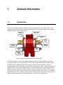
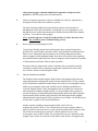
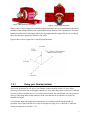
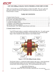
Faraday Isolator Medium Power ISO Series User’s Manual ii Preface Warranty Newport Corporation warrants that this product will be free from defects in material and workmanship and will comply with Newport’s published specifications at the time of sale for a period of one year from date of shipment. If found to be defective during the warranty period, the product will either be repaired or replaced at Newport's option. To exercise this warranty, write or call your local Newport office or representative, or contact Newport headquarters in Irvine, California. You will be given prompt assistance and return instructions. Send the product, freight prepaid, to the indicated service facility. Repairs will be made and the instrument returned freight prepaid. Repaired products are warranted for the remainder of the original warranty period or 90 days, whichever is longer. Limitation of Warranty The above warranties do not apply to products which have been repaired or modified without Newport’s written approval, or products subjected to unusual physical, thermal or electrical stress, improper installation, misuse, abuse, accident or negligence in use, storage, transportation or handling. This warranty also does not apply to fuses, batteries, or damage from battery leakage. THIS WARRANTY IS IN LIEU OF ALL OTHER WARRANTIES, EXPRESSED OR IMPLIED, INCLUDING ANY IMPLIED WARRANTY OF MERCHANTABILITY OR FITNESS FOR A PARTICULAR USE. NEWPORT CORPORATION SHALL NOT BE LIABLE FOR ANY INDIRECT, SPECIAL, OR CONSEQUENTIAL DAMAGES RESULTING FROM THE PURCHASE OR USE OF ITS PRODUCTS. First printing 2005 © 2005 by Newport Corporation, Irvine, CA. All rights reserved. No part of this manual may be reproduced or copied without the prior written approval of Newport Corporation. This manual has been provided for information only and product specifications are subject to change without notice. Any change will be reflected in future printings. Newport Corporation 1791 Deere Avenue Irvine, CA, 92606 USA P/N 44757-01 Rev. C iii Preface Technical Support Contacts North America & Asia Europe Newport Corporation Service Dept. Newport/MICRO-CONTROLE S.A. 1791 Deere Ave. Irvine, CA 92606 Zone Industrielle Telephone: (949) 253-1694 45340 Beaune la Rolande, France Telephone: (800) 222-6440 x31694 Telephone: (33) 02 38 40 51 56 Asia Newport Opto-Electronics Technologies 253 Aidu Road, Bld #3, Flr 3, Sec C, Shanghai 200131, China Telephone: +86 21 5046 2300 Telephone: +86 21 5046 2323 Newport Corporation Calling Procedure If there are any defects in material or workmanship or a failure to meet specifications, promptly notify Newport's Returns Department by calling 1-800-222-6440or by visiting our website at www.newport.com/returns within the warranty period to obtain a Return Material Authorization Number (RMA#). Return the product to Newport Corporation, freight prepaid, clearly marked with the RMA# and we will either repair or replace it at our discretion. Newport is not responsible for damage occurring in transit and is not obligated to accept products returned without an RMA#. E-mail: [email protected] When calling Newport Corporation, please provide the customer care representative with the following information: Your Contact Information Serial number or original order number Description of problem (i.e., hardware or software) To help our Technical Support Representatives diagnose your problem, please note the following conditions: Is the system used for manufacturing or research and development? What was the state of the system right before the problem? Have you seen this problem before? If so, how often? Can the system continue to operate with this problem? Or is the system nonoperational? Can you identify anything that was different before this problem occurred? iv Preface Table of Contents Warranty ..................................................................................................... ii Technical Support Contacts ....................................................................... iii Table of Contents ....................................................................................... iv 1 General Information 1 1.1 Introduction ............................................................................................1 1.2 Safety .....................................................................................................2 1.3 Operation................................................................................................4 1.3.1 Using your Faraday Isolator ......................................................6 1.3.2 Tuning your Faraday Isolator ....................................................9 1.4 Specifications .......................................................................................11 2 Factory Service Information 12 2.1 Service Form ........................................................................................12 1 General Information 1.1 Introduction Your Newport Faraday Isolator is essentially a uni-directional light valve. It is used to protect a laser source from destabilizing feedback or actual damage from back-reflected light. Figure 1 below identifies the main elements of your Faraday Isolator. MAGNET HOUSING BASE CLAMP WITH SCREW TRANSMISSION ARROW ESCAPE PORT INPUT POLARIZER OUTPUT POLARIZER SERIAL NUMBER BASE PLATE MODEL NUMBER Figure 1: Newport’s 532-980nm Medium Power Faraday Isolator The Faraday Isolator is a cylindrically-shaped magneto-optic device. Strong Neodymium Iron Boron permanent magnets are used to generate high (>10,000 Gauss) axially-oriented fields within the magnet housing. The strong longitudinal field causes 45 degrees of non-reciprocal polarization rotation for propagating light via the Faraday Effect in the Terbium Gallium Garnet ("TGG") crystal located within the magnet housing. In operation, the magnet housing is sandwiched between input and output polarizers that have their transmission axis oriented 45 degrees relative to each other to account for the 45 degrees of Faraday rotation in the TGG crystal in the forward (transmission) direction. In the reverse (isolation) direction the non-reciprocal Faraday rotation and the 45 degree polarizer transmission axis angle add so that the polarization transmitted by the output polarizer is rejected at the input polarizer. 1 Your Newport Faraday Isolator is labeled with a serial number on the base clamp of the device. 1.2 Safety The operational hazards presented to operating personnel by the use of your Newport Faraday Isolator are listed below. An explanation of how the Faraday Isolator is designed, together with procedures users can employ to eliminate or minimize these hazards are also listed. 1. Danger of sharp ferromagnetic objects being attracted to the residual permanent magnet fields outside of the isolator. This hazard is of most concern if such fields cause flying objects when being handled. Your Newport Faraday Isolator requires strong internal magnetic fields to operate properly. Efforts have been made to minimize external fields from the device while still maintaining a relatively small and cost effective package. The external fields are designed to be well within federal safety guidelines which limit external fields from magnetic devices to be less than 2K Gauss at a radial distance of 5cm from the outside of the device. However, such fields can be sufficient to attract nearby objects such as knives and razor blades. Should attraction of such objects begin to occur there would be a strong attractive force directing these objects towards the interior of the magnet housing. This could be particularly likely to result in injury (e.g. a cut or puncture wound) if such attraction occurred while the device was being handled – particularly if a body part of the operating personnel is near a beam Aperture (i.e. end) of the device. To minimize the above risks remove all loose ferromagnetic objects from the path over which your Newport Faraday Isolator is to be moved prior to attempting to move it. Do not pick up the isolator by its ends (i.e. apertures) where the attractive magnetic fields are strongest. Always pick the isolator up along its sides. 2. Reflection of rejected beams from the input and output polarizer. The polarizer covers have been positioned at the factory to block all beams rejected from the polarizers. In the event that your Faraday Isolator will be used with transmitted average powers in excess of 25W, or will block backward propagating light in excess of 0.5W average power, these polarizer covers must be rotated to allow rejected beams to exit (see Figure 1) onto user supplied beam dumps. These rejected beams can represent a hazard to users and/or their colleagues. Care must be exercised to ensure that all rejected beams (both transmission and isolation directions) are accounted for and terminated into functional beam dumps. Wherever possible keep the strongest rejected beams in the horizontal plane of the table or otherwise safest direction (typically down into the table). Always wear laser 2 safety glasses/goggles consistent with all laser frequencies and power levels present. See the following sections for further details. 3. Failure of operating personnel to observe standard laser safety by sighting down through the isolator when laser radiation is present. The optical elements within the Newport Faraday Isolators can be transmissive throughout the visible and near infrared. Consequently it is never appropriate to view through the device in either the transmission or isolation direction when laser radiation is present – even with laser safety goggles. Never sight through your Newport Faraday Isolator in either direction when there is any possibility of laser radiation being present. 4. Harm caused by external magnetic fields. Your Newport Faraday Isolator has been designed to meet existing federal safety guidelines for external fields as noted previously. Such guidelines could change in the future as more information becomes known or reviewed regarding the interaction between magnetic fields and human health. Since there exist various claims regarding the potential harmful (and beneficial!) effects of magnetic fields on humans it is prudent to limit interaction with these fields as much as possible. Personnel with any magnetically-sensitive implants such as pacemakers should consult their medical doctor regarding any potential complications which could arise from the isolator external magnetic fields. 5. Other non-health related hazards. The Faraday Isolator external magnetic fields can draw ferromagnetic objects into the magnet housing that can damage the optical elements within the device. Keep a suitable area in all directions around the Faraday Isolator clear of any loose ferromagnetic objects. Ideally, use non-magnetic tools (such as stainless steel or titanium) and hardware to secure the Faraday Isolator. If only ferromagnetic tools are available use extreme care when using them around the Faraday Isolator. It is always helpful to bring such tools towards an aperture (or end) radially rather than along the optical beam path. Doing this ensures that the fields will tend to pull such objects into the magnet housing endplate rather than into the optical aperture. Where possible use two hands, one to hold the tool and the other to guide it to the desired destination. Another concern regarding external magnetic fields is their effect on magnetically-sensitive devices. The external fields are strong enough to induce a pulse of current in electronic devices (such as digital watches) that can destroy them. The fields can also disrupt the operation of other mechanical devices with ferromagnetic parts in them. Finally, the external fields can erase information from magnetic strips such as are found on credit and ID cards. Remove all magnetically3 sensitive materials and devices such as watches, computer hard drives and magnetic strips from operators prior to working in the proximity of an isolator. 1.3 Operation BASE CLAMP WITH ADJUSTMENT SCREW INPUT POLARIZATION AXIS LINES H, 45, V POLARIZER MOUNT CLAMP INPUT POLARIZATION AXIS AND DIRECTION OF REJECTED BEAM AND SET SCREW FOR ADJUSTING WAVEPLATE INPUT POLARIZER MOUNT WAVEPLATE POLARIZER DUST COVER Figure 2: View of Faraday Isolator and Tuning Features With the polarizer cover off, a polarizing beamsplitter cube (“PBSC”) can be seen inside the input polarization mount. The inscribed arrow on the base clamp displays the transmission direction. The output PBSC is seen to be oriented with its transmission axis rotated 45 degrees relative to the input PBSC. The input polarization shown is vertical. The central magnet housing together with the TGG crystal residing in its center forms a Faraday Rotator. The Faraday Rotator rotates the input transmission axis by 45 degrees so that transmitted light has a polarization aligned with the output transmission axis. The input and output PBSCs work in conjunction with the central Faraday Rotator to form a Faraday Isolator. Though the overall size of the device varies depending on the model, the operation of the polarizer mounts are identical. 4 Figure 3: Horizontal Input Polarization Figure 4: Vertical Input Polarization Figure 3 shows a device aligned for a horizontal input polarization. The screw-hole located on the side of the PBSC mount indicates the direction of polarization and the direction of the rejected beam. This is the beam that is reflected off of the input polarizer, having originated at the output of the device, traveling in the reverse direction, opposite the direction of the arrow. Figure 4 shows a device aligned for a vertical input polarization. 1.3.1 Using your Faraday Isolator Observe the guidelines for safe use of your Faraday Isolator found in Section 1.2 above when removing your isolator from its shipping container. Do not remove the protective dust-cover end caps from the polarizers until the device is in a clean, relatively dust-free environment. Save the protective end caps, packaging material and containers in the event that the device should ever need to be returned to Newport. Verify that the Input and Output polarization states are consistent with the intended mode of operation. If not, either send the device back to Newport (see Page iii) or, if desired, re-adjust the isolator as required (see Section 1.3.2). 5 With the source laser off, or running at very low power (less than 250mW), position the Faraday Isolator such that the source laser beam can be directed through the Input Aperture. Critical alignment of the Faraday Isolator should be done at low power (less than 250mW) in order to prevent optical damage to your isolator or laser source. At this point, the Faraday Isolator should be secured to the work surface with two (2) 1/4 - 20 or M6 screws – one for each slot in the baseplate flanges. Alternatively, the baseplate may be removed from the baseclamp by removing two 8-32 screws on the bottom side of the base plate. Then, the baseclamp/isolator assembly may be mounted to a standard laboratory post with an 8-32 set screw or may be conveniently mounted into laser systems, minimizing the required footprint of the device. Steel (ferromagnetic) ball drivers or other such wrenches will be attracted to the external magnetic field surrounding the device. If possible use anti-magnetic stainless steel or titanium tools. If ferromagnetic tools are used it is desirable to introduce them slowly toward the device from the sides along the direction of the baseplate flange slots. If the Faraday Isolator will be used with average powers in excess of 12W transmitted or 0.5W rejected backward propagating radiation (please consult damage threshold specifications for operating range), the Polarizer Covers will need to be rotated so that the Escape Ports allow rejected polarization light to be safely dumped onto a beam dump. Failure to allow these rejected polarizations to escape can cause the device to heat up. Such heat can degrade the performance of the Faraday Isolator, or in severe cases, cause damage to optical components in the isolator. While working with low alignment level power and wearing safety glasses, physically grasp the Polarizer Cover and rotate it by 90 degrees. Any rejected polarized beams (in either the forward or backward propagating directions) can now exit the Polarizer Cover. Use an IR viewer or IR card to locate these beams. Ensure that they are terminated on beam dumps consistent with the maximum amount of power that may be in such termination points. In addition to high rejection (>27dB) of any undesired linear polarization component in transmission, the Input and Output PBSCs may reflect as much as 3% of the desired transmitted polarization. Backward propagating rejected beams will exit from the PBSC from the side of the PBSC mount containing the screw hole (on the input polarizer). Forward transmission rejected beams will exit from the other side of the PBSC and are minimized when the input beam is polarized parallel to the input polarizer. If the Faraday Isolator is used in an application where strong reflections and/or optical gain elements (amplifiers) exist, there may be very high power rejected beams for backward propagating light at the input polarizer. If the average power levels used do not exceed 12W transmitted or 0.5W of backward propagating power then the Polarizer Covers may be kept in their factory positioned orientation – that is, with all rejected beams blocked by the Polarizer Cover. However, if the Faraday Isolator is to be used with very high peak intensities it is prudent to allow rejected beams to escape on the external beam dumps to prevent any ablation damage to the nickel-plated Polarizer Covers. Follow the same procedure above for high average powers in order to safely terminate all rejected beams. Note that the direction of the screw hole on the output polarizer indicates the direction of the component of rejected power from a backward propagating beam that is not parallel to the output polarizer. 6 Figure 8: Dimensions of Medium Power Faraday Isolator in Inches 1.3.2 Tuning your Faraday Isolator A. Adjusting Input Polarization The transmission axis of the Input Polarizer is parallel to the scribe line found on the Input Polarizer Endplate. If the linear polarization of the laser source is geometrically known, aligning the Input Polarization of the Faraday Isolator to that of the laser source is straightforward. Simply loosen the #2-56 socket head Baseplate Clamp Screw in the Baseplate until the magnet housing rotates freely. Continue to rotate the magnet Housing until the Input Polarizer transmission axis scribe line is aligned to that of your laser source. If the direction of any rejected polarizations at the input polarizer is important they can be determined by noting that the “dot” superimposed on one of the Endplate scribe lines is associated with the direction that a backward propagating beam will be directed. Re-tighten the Baseplate Clamp Screw. B. Fine Wavelength Adjustment Each of the 532, 650, 780, 850, and 980nm isolators may be tuned over the wavelength range specified in section 1.4. Tuning is achieved by adjusting the relative angle between the input and output polarizers. For wavelengths longer than the central wavelength, the Faraday rotation is less than 45 degrees. For wavelengths shorter than the central wavelength, the Faraday rotation is more than 45 degrees and therefore, the device may be tuned for maximum extinction with a small transmission loss, illustrated by the wavelength tuning curves in section 1.4. The 3dB bandwidth of the isolators ranges from 26nm at 532nm to 46nm at 980nm, in increasing value. For maximum extinction, manually tune the device to the appropriate wavelength. 7 With the source laser operating at an average power of 500mW or less (attenuate the beam if necessary to achieve such a low power level), direct the source laser beam through the Faraday Isolator in the reverse direction – through the Output Polarizer first and then through the Input Polarizer. Use an IR viewer to view the transmitted radiation to ensure that it is directed onto a Power Meter. The Power Meter should be sensitive enough to detect power levels below 0.05mW (or 40dB of the input signal used). As a reference, 40dB is a factor of 1:10000 and 10dB is a factor of 1:10. If necessary, loosen the Baseplate Clamp Screw to allow the Output Polarizer transmission axis to be rotated parallel to the source laser polarization axis. Re-tighten this screw when complete. Loosen the button head Input Polarizer Clamp Ring screws just enough to that the Input Polarizer Mount can be rotated (the Input Polarizer is opposite to the laser source at this point). Rotate the Input Polarizer Mount until a minimum reading is indicated on the Power Meter. Re-tighten the Input Polarizer Clamp Ring Screws. The minimum reading should be at least 27dB of the input signal. If not, call Newport for assistance (see Page iii). The Faraday Isolator is now optimized to operate at the new laser source operating wavelength. It may now be installed for operation in transmission with the laser source as per Section 1.3.1 and the procedure outlined in Section 1.3.2 A. C. Changing the Direction of the Output Polarizer Rejected Beam Steering Section A above describes how to orient the Input Polarizer to steer rejected beams as desired. If the Output Polarizer rejected beam steering direction needs to be changed, loosen the three Output Polarizer Clamp Screws and rotate the Output Polarizer Mount by 180 degrees before re-tightening the screws. Depending upon the isolation requirements, follow Procedure B from above in order to fully optimize the isolation of the device with this Output Polarizer orientation. D. Waveplate Option and Adjustment It is possible to order a Faraday Isolator with a half-waveplate on the output. Should any of the above adjustments become necessary, or if the desired output polarization changes, the waveplate will need to be adjusted. To re-align the waveplate loosen the radially oriented set-screw in the output polarizer mount and rotate the waveplate until the desired output polarization is achieved. Retighten the waveplate set-screw. Do not over-tighten. A waveplate may also be used in the input of the device if necessary. 8 1.4 Specifications Center Wavelength Tunable Range (nm) (nm) Model Isolation (dB) Transmission (%) CW Damage Threshold (KW/cm2) Pulsed Damage Threshold (J/cm2 at 10ns) ISO-04-532-MP 532 500-600 27-35 >88 2 1 ISO-04-650-MP 650 600-680 27-35 >88 2 1 ISO-04-780-MP 780 730-830 27-35 >88 2 1 ISO-04-850-MP 850 800-880 27-32 >88 2 1 ISO-04-980-MP 980 950-1010 27-32 >88 2 1 Two-State Option: Faraday Isolators may be used in series to obtain 60±dB isolation, mounted on a common baseplate. Mounting Options: Cylindrical housings are inserted into a clamping device that provides 8-32 screw holes and may be mounted onto a standard post. All devices include a base for mating with ¼ -20 screw holes. Notes: 1. Transmission: This is measured form the center wavelength. Tunable transmissions will be wavelength dependent. Please consult the spectra below. These values are based on absolute minimum allowable transmission and on average will be >90%. 2. Damage Threshold: Damage threshold is limited by cemented optics and broadband AR coatings for wavelength tunability. For higher damage threshold applications, please contact Newport. 3. Operating Temperature: Performance of Newport’s Faraday Rotators/Isolators is related to operating temperature. For information on the effect of operating temperature on Newport’s Faraday Rotators/Isolators, please review our technical bulleting, Effects of Temperature on Newport’s Faraday Rotators/Isolators. 4. Center Wavelength: This refers to the wavelength specified for 45 ± 2 degrees and is not necessarily the median of the wavelength range. 5. Tunable Transmission: The below graphs show the transmission of the device following tuning as per instructions in section 1.3.2 B. 9 2 Factory Service Information 2.1 Service Form Newport Corporation U.S.A. Office: 800-222-6440 FAX: 949/253-1479 Name __________________________________ Return Material Authorization # _____ (Please obtain RMA# prior to return of item) Company ________________________________________________________ Address ______________________________ Date _________________________ Country ________________________________ Phone Number __________________ P.O. Number ____________________________ FAX Number ___________________ Item(s) Being Returned: Model # ______________________________ Serial # ______________________ Description Reason for return of goods (please list any specific problems) 10 Notes: