1
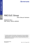
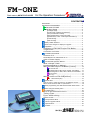
FM-ONE
Flash memory MCU PROGRAMMER
For the Operation Procedures
CONTENTS◆
IMPORTANT..................................................................................... 1
ON-BOARD PROGRAMMER........................................................... 2
FM-ONE FUTURES ............................................... 2
SPECIFICATIONS ................................................... 2
【Package Style】 ................................................................. 2
【Product and contained accessories】 ................................ 3
【The provided CD includes】 ............................................... 3
【Brief specifications of the main body】 ............................... 4
【Specifications of FM-ONE Project File Maker】 ............... 4
【Parts names】 .................................................................... 4
【Side of body】 .................................................................... 4
Battery Holder Guidance ........................................................... 5
About some changes on display for upgrade ............................ 6
Preparation ................................................................................ 7
Installation of FM-ONE Project File Maker ............. 7
Target board ............................................................ 8
Connector and Cable................................................ 8
CONNECTION IMAGE ............................................................ 8
Insertion of CF ......................................................... 8
RECOGNITION OF USB DEVICE OF CF .............................. 8
Order of Power Supply.............................................. 8
Fundamental Operation Method .............................................. 8
What is PROJECT FILE? .............................................. 8
Fundamental Write-in Method .................................. 9
With FM-ONE Project File Maker 【Online】............ 10
A1: Save/Load .............................................................. 11
Operating tab for R8C, M16C, M32R, 740 families. ...... 12
Operating tab for V850, 78K0, 78K0R, RL78 families. .. 13
A2: Program.................................................................. 14
A3: Log.......................................................................... 15
With the switch on FM-ONE【Offline】 ...................... 18
B : Write switch (OK) ................................................... 18
Specific MCU............................................................................ 19
How to write in external memory of ROMless articles ....... 19
What cannot be done with a special MCU. ...................... 19
About programming onto R8C・M16C・M32R・R32C series...... 20
Before using RL78 family MCU ................................................ 22
Troubleshooting ........................................................................ 23
Items to be confirmed at errors ............................... 23
Timing Chart ......................................................... 24
Errors while writing .............................................. 25
Other errors .......................................................... 25
Correspondence MCU.............................................................. 26
Version upgrade method......................................................... 26
Optional items......................................................................... 26
Includes .................................................................................. 27
株式会社
REV.2.0.0.0
Hokuto Denshi Co; ltd
IMPORTANT
Do not use the FM-ONE before reading this user’s manual
◆MATTERS ON SAFETY
●Make sure that you fully understood this user’s manual, before using the FM-ONE.
Reading this manual is the responsibility
of the FM-ONE users to fully understand all the matters.
●This user’s manual must be kept by the holder and when there is anything unclear about the use of the product, read it again
and again before you fully understand.
●FM-ONE is made up of a programming writer which rewrites programs to a Flash ROM built-in microcomputer made by
Renesas Electronics Corp. The FM-ONE is not to be used for any other purpose other than what is specified in this manual.
●Designs, functions and specifications of the FM-ONE are subject to change without notice with a view to enhancement of
performance or safety. Some diagrams in this manual may sometimes differ from the product.
●This manual and the product are protected by copyright and the industrial property right, and all rights are the property of
HokutoDenshi Co., Ltd. All rights are reserved.
●HokutoDenshi always reviews and takes due measures for safety of users. We are, however, unable to foresee every
potential hazard and improper use. Also, all cautions are not always described in this manual, and, therefore, understanding
and judgment are the responsibility of the users for the interest of proper and safety use of the product.
WARNINGS
Failure to adhere to the following warnings may result in possible heat, smoke and fire damages to the FM-ONE and
surrounding systems.
1. Don’t disconnect and don’t reconnect power cables while power is on.
2. Don’t remove and don’t replace any circuit while power is on.
3. Don’t use power voltages other than what is specified in circuit diagram.
4. Be sure to use the correct connector cables when connecting between the FM-ONE, MCU and peripheral systems.
LIMITED GUARANTEE
HokutoDenshi Co., Ltd. guarantees that the FM-ONE can be used by the usage described in this manual by HokutoDenshi
Co., Ltd. and guarantees that the FM-ONE has been produced correctly and is free of any defects in materials and finish of the
product. The FM-ONE is guaranteed for 1 year after purchase.
This guarantee is not valid in the following cases:
1.
2.
3.
4.
Fires, earthquakes, floods, accidents caused by a third party.
Premeditation, error or omission, improper use and/or in an improper environment.
The product has been altered in any way or tampered with.
The method of use has resulted in damage to the product, or a defect with the product.
WHAT THIS GUARANTEE DOES NOT INCLUDE
HokutoDenshi Co., Ltd. guarantees the product only when the product is used correctly as described in this manual. This
guarantee is not valid of the product misused for purposes other than that is specified in this manual. The guarantee is valid
only for the materials used to construct the product.
HokutoDenshi Co., Ltd. accepts no responsibility for whatever costs associated directly (or indirectly) with damaged (or faulty)
goods. This guarantee is valid for only the original purchaser of the product.
For the damages arose cumulatively, when the guarantee explicitly covers the damages, the guarantee is limited to received
value of the product price no matter what the reasonsare.
Any application for retailing the product by a third party can not be accepted. The purchaser of the product assumes all
responsibility after the purchase of FM-ONE.
Prices of the product and its attachments are subject to change without notice.
1
FM-ONE
HOKUTO DENSHI CO;LTD; 株式会社
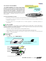
ON-BOARD PROGRAMMER
Verification at the scene
Presentation of functional comparison
Small lot multiproduct
production
Version upgrade
and maintenance
after release
Our on-board programmer, when mounted, readily downloads
user programs to the Flash built-in microcomputer made by Renesas
Electronics Corp. When mounted, the on-board programmer is able
to not only examine the system but also rewrite user programs even
after the hardware itself is completed. These advantages can be
extensively used from development to maintenance of various
programs. Our product supports users’ efficient production in various
ways such as shortening of the duration of development, saving the
effort of providing a verification environment, and reduction of
inventory goods.
ON-BOARD PROGRAMMER FEATURES
While writing, an automatic control function in boot mode lets MCU board write in an operation mode.
This programmer is best for the development of writing control programs, save the need for validation, and can be
developed in a short duration.
The target interface can be used together with our on-board programmer or independently depending on
circumstances.
FM-ONE FUTURES
FM-ONE is characterized by an easy handling of the user programs with CF (compact flash). We have made efforts in
improving for convinience. For example, those functions are left unchanged that have been well received with the existing
on-board programmer FLASH2 and FLASH MATE5V1.
The system, serving as a USB storage device, saves project files in the CF.
With a 20-letter x4-line LCD as well as a switch, this system makes possible to write without a PC.
Power is supplied to the main body by three methods: a USB Bus power, an AC adapter, and nickel metal-hydride
batteries. *Two size AA batteries
SPECIFICATIONS
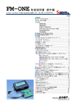
【Package Style】
Corrugated carton Size…212×277×62mm
Package seal and products serial number
Serial seal
Package seal
FM-ONE
Top of the box,Back side of the Programmer
body, inside of the battery box,
and on the enclosed CD
Contents
Packing sheet
Application CD
Aircushion
Programmer
Target cable
AC adapter
* The compact flash is put on the programmer body.
FM-ONE
HOKUTO DENSHI CO;LTD; 株式会社
2
【Product and contained accessories】
On-board programmer FM-ONE body ............ one
Software (attached CD) .................................................. one
Compact flash........................................................................... one
AC adapter .................................................................................. one
USB connection cable (20P Flat cable 30cm)one
User’s manual: one operation edition and one material edition
*Instruction manual (how to use) and Information book is supposed to be recorded in an attached CD from Mar.05.2008.
* A USB cable can be bought on the market.
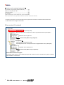
【The provided CD includes】
For English OS
Demonstration(Categorized by HSB)
Manual (English PDF manual) and The list of supported flash memory MCU(PDF)
Installation file for English OS
Double click (When using in English)
For Japanese OS
Demonstration(Categorized by HSB)
Manual(Japanese PDF manual) and The list of supported flash memory MCU(PDF)
Installation file for Japanese OS
Double click (When using in Japanese)
About Demonstration Program
In the demo folder, there are LED’s blinking programs with reference sources. MOT file among them is realized
quick evaluation of each board.
3
FM-ONE
HOKUTO DENSHI CO;LTD; 株式会社
【Brief specifications of the main body】
Writable MCU:
Flash On-chip Memory made by Renesas Electronics Corp
of single power supply and H8SX/1650, H8SX/1651 Expternal memory
*MCU that appears in this document is the flash memory edition.( H8SX/1650, H8SX/1651 group is excluded.)
Writing mode:
On-board programming
Boot mode
Writing voltage in the target: 5V or 3.3V (voltage span for UserVcc:2.5~5.5V
Consumption current:
approx. 10mA)
Writable file format:
Motorola file (S format file) extension .MOT,
Intel HEX file (HEX format file) extension .HEX
CF available:
Attachment CF115-1G
Operation-checked CF:CF115-1G,CFS-64MX (I-O data Device Inc. )
SDCFB-32-801,SDCFB-64-801(Sun Disk Corp.)
* Up to 10 projects in the amount of memory can be used.
CF Interface specification: accepts FAT12/FAT16, 3V, sector size 512,
and less than 2GB.
*It’s users’ responsibility to use CF, whose operation is not checked by
HokutoDenshi Co., Ltd.
Power supply:
Attached AC100Vadapter, or two size AA nickel metal-hydride batteries
*The attached AC adapter is applicable in Japan.
DC+9V (DC+7V~+12V) Capacity: over 300mA, Jack: Centre minus (0V)
ø5.5mm/2.0mm
Do not use any articles other than the attached items as they may damage the
main body and MCU. Some expendables are sold separately.
*When using with batteries, It is recommended that nickel metal-hydride
batteries be replaced every hour though they do not die out.
*No battery is provided with the main body.
Body case size:
89×134×36mm (excluding the pronged top)
Weight :
260g (excluding batteries)
【Specifications of FM-ONE Project File Maker】
Attached application:
FM-ONE Project File Maker
Operation environment: Windows2000,XP,Vista,7 and 8.1. (Online writing is not available on Vista and 7.)
Japanese environment
*While using this application, don’t use other applications.
PC Interface:
USB port (Prepare a USB cable)
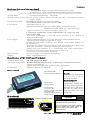
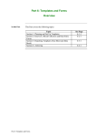
【Parts names】
PC interface(USB)
DC jack (attached adapter)
▼Main body LED
CF access:
Don’t remove the CF while light
is on as it runs a risk of
destroying saved data.
UserVcc・TX/RX access:
displays two-way
WRITE button
CANCEL button
communication
CF eject button
CF Access LED
UserVcc・TX/RX access LED
CF insertion slot
Parameter selection button
Target interface
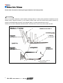
【Side of body】
between
the
main body and the target. Even
when USER VCC is powered on
and when the output of the
target TXD shows “Low”, LED
remains “OFF.”
Caution!
a swtich to update firmware.
This switch should be operated only when
the firmware needs to be updated.
※opposit side of target interface.
normal
firmupdate
FM-ONE
The home position of this switch is left side.
Do not operate this switch during the
device is working or the device gets
critical damage.
HOKUTO DENSHI CO;LTD; 株式会社
4
Battery Holder Guidance
Please read <Precaution> before placing the batteries into battery holder.
<Precaution>
Some of the alkaline batteries contain flexible insulating label to it. When placing that kind of batteries into the
battery holder, negative terminal (-) of the battery holder could come into contact with positive terminal (+)
inside of the flexible label as shown in the diagram below. It causes electrical short-circuit.
Please do not use the batteries described above. Electrical short-circuit may cause smoke and fire.
5
FM-ONE
HOKUTO DENSHI CO;LTD; 株式会社
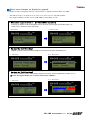
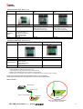
About some changes on display for upgrade
The display in LCD is changed as firmware’s and hardware’s upgrade as follows.(After Jan. 2009)
・ “FM-ONE file manager” was displayed on top of the screen, but it turns into “FM-ONE SYSTEM”.
・ The voltage of batteries (power source of FM-ONE) is shown.(Refer to 3-2)
● When power supply is turned on 【In Online/Offline operations】
・ In starting, the display as follows disappears in a few seconds and it changes into the idling state.(1-2)
・ “version xxxxx” means the version of firmware.
1-1 Old version
1-2 New version
● On stand-by 【In Online idling】
・ “USB/DC” is shown on the screen when FM-ONE is connected to the PC with a USB cable.(2-2 A)
2-1
Old version
2-2
New version
B
A
● On stand-by 【In Offline idling】
・ The display of “Battery symbol” and “Voltage” appears in the screen when FM-ONE Starts by offline.(3-2 C)
※In case of using AC adapter, the “C” part of 3-2 becomes ”USB/DC”.
3-1
Old version
3-2
New version
C
B
FM-ONE
HOKUTO DENSHI CO;LTD; 株式会社
6
Preparation
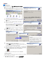
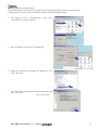
Installation of FM-ONE Project File Maker
<Procedure of Installation>
①
Set the attached CD into the CD drive of PC, start up
Explorer, and double click on the setup.exe from among
the files in the CD drive.
②
The installer in the right diagram starts up.
Confirm the instruction in the screen, and then click on
“次へ” (next) .
③
“The a to install FM-ONE Project File Maker” is
displayed on the screen.
When a folder different from the one designated on the
screen is to be selected, click on “参照” ( REFERENCE)
and select the desired folder according to the direction.
④
Leave the folder to install on the screen, and then click
on “次へ” (next).
Message “Start installation” is displayed. Check the
message and click on the indicated icon “Start
installation,” and the progress bar will appear and
installation will start.
Cautions!
The way messages are displayed may differ
from one PC another. For further information,
refer to user’s manual of Windows.
During installation, do not start other
applications software if circumstances permit.
If a required system file is being used,
installation may not be perfected and as a
result recovery is sometimes difficult.
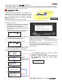
⑤
“Installation is completed” will be displayed.
Select “閉じる”(close), and the installer will cease to function.
If a message urging “Reboot PC,” appears, be sure to reboot your
PC before starting up FM-ONE Project File Maker
⑥
When the procedure (①~⑤)is made properly, an executable file
shortcut is produced both on the desktop and in HokutoDenshi
Folder by the following order: start menu→all programs.
To uninstall, start up the installer again and click on DELETE.
<Sample programs>
Sample programs of our MCU board products included in the attached
CD can be copied when necessary.
7
FM-ONE
HOKUTO DENSHI CO;LTD; 株式会社
Target board
Prepare MCU-set board which is equipped with a specified write-in interface.
For the write-in interface and I/F circuit diagram of the interior FM-ONE, refer to attached “User’s Guide.”
Connector and Cable
The connector model name and signal name are shown in the “User’s Guide.”
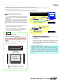
ON-BOARD PROPGRAMMING
BOOT MODE
Delete all of on-chip ROM, and then write the targeted
program.
CONNECTION IMAGE
ProjectFileMaker
In using the FM-ONE, the target board, FM-ONE
and PC must be connected as the diagram indicates,
on the right.
Prepare a target board according to our reference
circuit diagram, connect its write-in interface with the
FM-ONE body with the target connection cable, and
then insert CF (Compact flash) through CF insertion
slot.
To connect the FM-ONE body with PC, you
must use a USB cable (not provided).
Power is to be supplied to the FM-ONE body
from a USB bus when PC is operated, or
otherwise from the attached adapter.
USB
cable
Target board
From PC to CF
Flash on-chip microcomputer
MOT/HEX
From CF to on-chip FlashROM
Online operation
Attached AC adapter
Target board
or batteries
Flash on-chip microcomputer
Offline operation
From CF to on-chip FlashROM
Cautions!
Insertion of CF
Insert CF with its back face upward.
A slot is on the CF side. Hold the CF card with the
wider slot to the right against the FM-ONE and the
narrower one to the left, and the back face will be
upward.
Insert the CF card until you hear click so that the
injection button will pop up.
Right side (wider flute)
Left side (narrower flute)
(Back face)
Be sure to confirm if recognition is achieved properly
when a USB cable is connected and CF is inserted.
When a USB cable or CF is to be removed, be sure to cut
off the USB device.
How to cut off USB device
Click on the removal icon in the task bar on the bottom-right of
Windows, and then cut off the USB device according to the
direction on the screen. Make sure if it is cut off, and then
remove the CF or the USB cable. When “Disconnected USB”
is shown on the body display, it imust be disconnected properly.
Connection and disconnection can be done properly when PC is
not operating.
CF Card insertion slot
CF card
RECOGNITION OF USB DEVICE OF CF
CF inserted into the FM-ONE body is recognized as a USB
storage by PC.
※The card cannot be inserted with
the front face upward. Improper
insertion may damage the main
body.
FM-ONE
HOKUTO DENSHI CO;LTD; 株式会社
8
Order of Power Supply
When main body and the target board are powerd on and off, follow the orders below.
●Power ON:
Online
①Power In
②Power In
①Power In
②Power In
ProjectFileMaker
USB cable
Target board
Offline
PC
Attached AC adapter
or batteries
Target board
Flash on-chip microcomputer
Flash on-chip microcomputer
●Power OFF:
Online
②Power Off
①Power Off
②Power Off
①Power Off
ProjectFileMaker
USB cable
Target board
Offline
PC
Attached AC adapter
or batteries
Target board
Flash on-chip microcomputer
Flash on-chip microcomputer
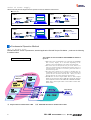
Fundamental Operation Method
What is PROJECT FILE?
Besides selection of files or parameters, attached application FM-ONE Project File Maker produces the following
five different files.
The number of files and folders that FM-ONE can detect is
up to 10.
Project files to be produced
When more than 10 files/folders are in the CF root, FM-ONE
will randomly display 10 on the LCD depending on the
number of the saved (Display order cannot be designated).
Files other than the Project File may be saved, however, in
order to avoid the trouble of confirming unnecessary files, it is
recommend that such files be saved in a particular folder as
circumstances permit.
Too many files should not be stored as checking may be
troublesome. (Unless you select those files as a project file, the
system will not check the internal files. But if you select
them by mistake, we cannot guarantee the results.)
FM-ONE tries to find a 'Project Folder' when it works. 'Project
Folder' has to have same name as HDP file's except the extension
and is supposed to have five files (HDP, TGP, TGW, HDU and HDH) .
Please make a new 'Project Folder' to store 5files in before 'Save'
button clicked.
Project File Maker
User program
MOT File
HDU
MOT2HDU
Hokuto Denshi
User File
TGW
MCU write-in
control
HDP
Parameter
File name
***.HDP
TGP
***.TGW
Target side
Protocol
HDH
Host side
Bootcontrol
***.HDU
***.TGP
***.HDH
W r i ti n g
※※
CF
FM-ONE
Target Board
MCU
Project name
Folder
※ Project name is written before .HDP
8
※
※※ MOT/HEX file name is written before .HDU.
FM-ONE
HOKUTO DENSHI CO;LTD; 株式会社
Fundamental Write-in Method
FM-ONE writes User Programs from project files saved in CF.
Writing can be started in two ways: one is done directly from FM-ONE Project File Maker, and the other is by operating the
write switch of the FM-ONE body.
Save ・・・
Fundamental Write-in Method
PC
To produce project files
from selected files and
parameters, and save
them.
FM-ONE
A1: Save/Load
A1: Save
CF
B: Write switch
Load
Project
【Online】
A2: Program Direct write-in
MCU
Target
With FM-ONE Project File Maker:
A1: Save/Load・・・ To produce project files into PC and CF, and to load them.
A2: Program・・・
【Offline】
B:
To write-in the project files automatically produced
With the switch of the FM-ONE body
Write・・・
To write in project files saved in the CF by operating the
switch of the FM-ONE body.
Load ・・・
To call projects that are
already
saved.
It
is
possible to directly write
what is loaded, or modify
the contents and save
them.
Program ・・・
To start writing projects
with PC.
After a message “Start
writing”
is
given,
communication
between
PC and FM-ONE turns to
an offline mode. When
writing is finished, it returns
to an online mode.
When user programs prepared with the MOT/HEX file format are to be used, the above five files must be
prepared as a project using FM-ONE Project File Maker. Writing is not possible by putting MOT/HEX file alone in
the CF.
Online operation: A1 and A2 and Offline operation B mentioned above will be described in the following page and later.
FM-ONE
HOKUTO DENSHI CO;LTD; 株式会社
9
With FM-ONE Project File Maker 【Online】
The operation of the FM-ONE Project File Maker is described.
Project File Maker
Connection to the FM-ONE body or the target board is not always necessary.
Connect the system when necessary as the diagram right shows. Target board
USB cable
From PC to CF
Prepare the user program in the MOT/HEX file format,
and then start the installed FM-ONE Project File Maker.
Refer to the following start-up direction:
MOT/HEX
Flash on-chip microcomputer FM-ONE
From CF to on-chip FlashROM
Online operation
Diagram to start-up To confirm version information, click on the HELP tab.
The tab which hid can be displayed.
Double-click on the Icon of
FM-ONE Project File Maker.
Display a detailed setup diagram.
Operation screen starts with a compact
screen hiding a detailed setup. To produce
a project file, click on the Details key.
Details screen displayed
screen display button
of file selection
User program (Select by MOT or HDU)
User program for Secondary area (Select by MOT or HDU)
Writing Control Program corresponding to MCU 【Automatic selection is possible by MCU Type name】
Writing Control Program for Secondary Area 【Automatic selection is possible by MCU Type name】
Clock mode, frequency, multiplication
factor
MCU Selection of type name
Transmission
rate
【Turn on when necessary】
Pin setup aiming at an automatic control to a
boot mode
Error message display
Language alteration
Japanese or English can be
selected.
*Some descriptions are
asynchronous
written only in Japanese.
clock synchronizer
To hide the detailed setup
screen, click on the Details
key again.
Establishment of
connection
Connected to the body.
OK
10
FM-ONE
HOKUTO DENSHI CO;LTD; 株式会社
A1: Save/Load
Select a file as well as a parameter as a project file to be SAVED.
As mentioned on the previous page, first of all, start FM-ONE Project File Maker to display a detailed setup screen.
①Selection of User Program
Select the prepared MOT/HEX file.
Click on the screen display button of file selection
and then select from among files displayed on
Windows.
▼ For User File 1, select a file for regular ROM areas,
and for User File 2, select a file for secondary (in a
specific MCU such as stacked modules or User
boot mats.)
▼ Those selected files are converted into one project
file and saved in a single HDP file.
▼ If selected files include an write-in address to an
area other than on-chip ROM area good for the
boot mode, a warning will appear.
File selection screen
display button
①File selection
②MCU
selection
②Selection of MCU type name
Select the target MCU from among type names.
Make selection through two stages: from the group
selection list to type name list.
▼ MCU on the list is a type name which can be
available at the moment. New MCU is now under
preparation. For further information, contact us.
▼ When necessary, the boxes of the right Clock
Mode Setting turn into an active mode (white
background) urging ENTER.
Mode…Clock Mode (Select from the pull-down list)
Xtal…Target Clock All MCU is indispensable.
Clock setting as needed
③Pin setting
④Rate selection
⑤Option
When saving is in progress, “Save” is displayed here.
When loading is in progress, “Load” is displayed.
(When saved in HDP, the frequency is rounded off to one decimal
place.)
CKM…Main Clock multiplication factor
CKP…Sub Clock multiplication factor
※Select from among the pull-down list.
⑥Save
Cautions!
Up to 10 projects can be displayed in the CF on the LCD. When more than 10
projects are in the CF, a display order cannot be designated. It is recommend that unused
files be saved in a particular folder.
④Selection of Transmission Rate
③Pin setup
While writing, the connected MCU pin is
automatically controlled according to the intended
set-up, High or Low. Writing in the target board in
an operation mode is readily done.
▼ Various pins are merely output but not monitored
and so writing is possible even when this function
is not used. Compare the operation mode with
the boot mode and connect them in the minimum
frequency.
▼ Unconnected lines can be used selecting Hi-Z.
Select a transmission rate between FM-ONE and Target MCU from among the pull-down list.
Boot…This rate is to be used by combining the target MCU at the time of Start writing. Select
an appropriate rate corresponding to the target clock within a range specified by the
target MCU.
▼ Setting value: 1200bps 2400bps 4800bps 9600bps 19200bps
Async…This is a rate of an asynchronous communication method when user program data
are transmitted. Select a rate with a smaller serial communications error rate by
Target Clock.
▼ Setting value:1200bps 2400bps 4800bps 9600bps 19200bps 38400bps 76800bps
*Setting values are displayed, larger than by the Boot selection.
Sync…This is a rate of a clock synchronized communication method, which is used when the
user program data are transmitted. To use this rate, SCK signal must be connected to the
Target Interface #19.
▼ Setting value: NONE (No need when unnecessary) 10K, 25K, 50k, 100K, 500K, 1M, 2M
⑤Options setting
Select from two options, verify and FF Skip.
▼ Verify…Apart from the one at the time of normal writing, after writing all the programs, the written in contents must be retrieved without ending the
boot mode to verify. You can choose from Csum (comparison in terms of checksum values) and Byte (Comparison in terms of bytes).
▼ FF Skip…When all the sizes of a serial write are FF data, skip writing and optional verifying in terms of bytes.
* It is recommended to do Verify to enhance the reliability of the programming.
⑥Click on SAVE key
Now that all items to be selected are completed, click on SAVE key, and save the project names on the specified destination.
▼ Right project name…Save the project name in English one byte characters. ★1
On the specified destination, HDP (Hokuto Denshi Project) is
saved in an extension form, and the same time, files are produced necessary for writing, which are stored and saved at the same place where HDP
is. After it is saved and if it is to be written in the offline with the USB removed, be sure to match the folder name with the file name. Otherwise, a
file name cannot be found on the LCD screen of the FM-ONE body.
▼ Destination to be saved…In Offline operations, be sure to save in the CF. It is only when 'Program' button is clicked that a new folder is made
automaticaly. The new folder for the project files is not made automaticaly when they are saved with 'Save' button.
*Note: Save key is valid only when MCU is selected.
Please do Unplug or Eject Hardware when take off a USB cable and writing in offline mode.
The project file is saved, which can be confirmed by loading the project file.
Click on Load key, and a screen display of file selection will be displayed.
Click on the saved file from the screen in a file selection mode.
It is possible to modify the loaded project if needed, to save again, as well as resume writing in the previous setup.
★1
The file name must be less than 8 characters.
The hierarchy of the directory has to be with in one.
FM-ONE
HOKUTO DENSHI CO;LTD; 株式会社
11
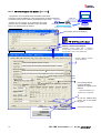
Operating tab for R8C, M16C, M32R, 740 families.
Please choose "R8C, M16C, M32R, 740 family" tab to program R8C, M16C, M32R, 740.
Boot settings are not needed. but an ID code has to be set in necessary.
Please refer to "IDcode" in hardware manual of each MCU for details.
①Selection of User Program
①specify "mot file"
②
"browse" button
MCU selection
list of series names.
list of MCU names.
Select the prepared MOT/HEX file.
Click on the screen display button of file selection
and then select from among files displayed on
Windows.
▼ Those selected files are converted into one project file and
saved in a single HDP file.
▼ If selected files include an write-in address to an area
other than on-chip ROM area good for the boot mode, a
warning will appear.
②MCU Selection
④
ID code settings
Select the target MCU from among type names.
Make selection through two stages: from the group
selection list to type name list.
▼ MCU on the list is a type name which can be available at
the moment. New MCU is now under preparation.
further information, contact us.
⑤
③
Other settings
For
③Selection of Transmission Rate★2
Select a transmission rate between FM-ONE and
Target MCU from among the pull-down list.
④ID code settings
Com settings
⑦Select high-speed
programming of R8C/Lx series
"FF" is shown in each edit box on choosing MCU
name.
The number of enabled boxes is up to MCU which is
chosen.
⑤Other settings
Please refer to ⑤ of page 9 for the details.
⑥Save
⑥Click on SAVE key
Please refer to ⑥ of page 9 for the details.
⑦Select high-speed programming of
R8C/3x★3,R8C/Lx series
When saving is in progress, “Save” is displayed here.
When loading is in progress, “Load” is displayed.
When the voltage is 4.5V~5.5V, the programming
speed goes up (please check the box).
★2
Boot…This rate is to be used by combining the target MCU at the time of Start writing. This setting is unnecessary for R8C, M16C, M32R, 740
Family.
Async…This is a rate of an asynchronous communication method when user program data are transmitted.
communications error rate by Target Clock.
▼ Setting value:9600bps 19200bps 38400bps 250Kbps 500Kbps 1Mbps
Select a rate with a smaller serial
Sync…This is a rate of a clock synchronized communication method, which is used when the user program data are transmitted. To use this
rate, SCK signal must be connected to the Target Interface #19.
▼ Setting value: NONE (No need when unnecessary) 10K, 25K, 50k, 100K, 500K, 1M, 2M
★3
12
MCU of R8C/32A, 33A, and 35A(354A,355A,356A) can’t be used.
FM-ONE
HOKUTO DENSHI CO;LTD; 株式会社
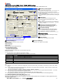
Operating tab for V850, 78K0, 78K0R, RL78 families.
Please choose "V850, 78K0, 78K0R, RL78 family" tab to program V850, 78K0, 78K0R, RL78 them.
Boot settings are not needed.
①Selection of User Program
①specify "mot file"
"browse" button
②CPU settings
Communication form setting
list of series names.
list of MCU
③Com settings
④Clook Mode Settings ⑤Voltage Setting
Select the prepared MOT/HEX file.
Click on the screen display button of file selection and
then select from among files displayed on Windows.
▼ Those selected files are converted into one project file and
saved in a single HDP file.
▼ If selected files include an write-in address to an area other
than on-chip ROM area good for the boot mode, a warning will
appear.
②CPU Settings
Select the target MCU from among type names.
Make selection through three stages: Series →MCU
name → Uart★4.
▼ MCU on the list is a type name which can be available at the
moment. New MCU is now under preparation.
information, contact us.
⑥Other settings
For further
③Selection of Transmission Rate★5
Select a transmission rate between FM-ONE and
Target MCU from among the pull-down list.
⑦Security Settings
④Clook Mode Settings
Please input the target’s clock mode and frequency.
Mode…Clock Mode (Select from the pull-down list)
Xtal…Target Clock All MCU is indispensable.
(When saved in HDP, the frequency is rounded off to one decimal place.)
⑤Voltage Setting
Please input the voltage when selecting RL78 family.
(e.g.) 2.5 (e.g.) 5.0
⑧Save
⑥Other settings
When saving is in progress, “Save” is displayed here.
When loading is in progress, “Load” is displayed.
⑦Security Settings
★6
Reprogramming from the others can be controlled.
Disable Program
Disable Block Erase
Disable Chip Erase
Disable Read
Disable Boot Block Cluster Reprogramming
Flash Shield Window function
Flash Shield Window Start Block
Flash Shield Window End Block
Please select start block and End block to set the window range when
selecting RL78 family.
Please refer to ⑤ of page 9 for the details.
⑧Click on SAVE key
Please refer to ⑥ of page 9 for the details.
★4 Communication form is different in the series of MCU.
Please choose the optional communication form fitted to each series.
Uart
Meaning
UARTx
Serial communication by UART.
CSIBx+HS
Serial communication by CSIB+HS(Handshake).
UART_OSC
Serial communication by UART (Uses X1 clock).
UART_FMCLK
Serial communication by UART(Uses the clock of “20-16pin 78K0” which is sold separately).
CSIx
Serial communication by CSI.
TOOL0
Serial communication by single line UART.
x:An optional number
★5
Boot…This rate is to be used by combining the target MCU at the time of Start writing. This setting is unnecessary for V850, 78K0, 78K0R
Family.
Async…This is a rate of an asynchronous communication method when user program data are transmitted. Select a rate with a smaller serial
communications error rate by Target Clock.
▼ Setting value:9600bps 19200bps 31250bps 38400bps 76800bps 115200bps
Sync…This is a rate of a clock synchronized communication method, which is used when the user program data are transmitted. To use this
rate, SCK signal must be connected to the Target Interface #7.
▼ Setting value: NONE (No need when unnecessary) 10K, 25K, 50k, 100K, 500K, 1M, 2M
★6
Security Settings are cleared by Chip Erase except for “Disable Chip Erase” and “Disable Boot Block Cluster Reprogramming”.
In FM-ONE, Chip Erase carried out automatically.
Note: About programming onto V850・78K0・78K0R series
An option board which fit each series is necessary. As for the details, please refer to the page 20, ”About programming onto
V850・78K0・78K0R series”.
FM-ONE
HOKUTO DENSHI CO;LTD; 株式会社
13
A2: Program
To start writing from FM-ONE Project
File Maker, click on the Program key with
File/Parameter in a selection mode.
To program, be sure to connect the main
body, the USB cable and the target board as
in the diagram on the right diagram.
ProjectFileMaker
USB cable
Target board
Flash on-chip microcomputer
From PC to CF
MOT/HEX
FM-ONE
From CF to on-chip FlashROM
Online operation
There are actually two operational procedures as follows:
Select the file and parameter as shown in the previous page, and click on Program.
A new project, which is not saved yet, is automatically saved under the name of “Default” and writing is started.
Load the project file saved following the direction in the previous page, and then click
on Program.
An existing project file, which has been saved before, is automatically saved (overwritten) in the CD under its original
name and then writing is started.
Likewise in the previous page, start FM-ONE Project File Maker.
When a new project is set up, or when the existing program is
loaded to resume writing in it, configure your computer in DETAILS
mode and click Program.
When the existing project is loaded and written in without
modifying, load the project leaving the screen below as it
is and click on Program.
Saving is executed and writing will immediately start.
※ Program key is
valid only when MCU
is selected and FM-
ONE is connected.
When Program
isbeing executed,
“Program”
is displayed here.
A new project is saved under the name of default and writing
is started, while an existing project is SAVED under the
original name and likewise writing is started.
Writing started, to an offline mode
Completion of writing
When writing is properly completed, a message
to the effect is displayed on the PC window.
Log.txt indicating successful completion is
produced in the project file.
14
Error occurrence
Automatically reset to ONLINE An error message is displayed on the PC screen.
Errors are produced in the project file as log.txt.
FM-ONE
HOKUTO DENSHI CO;LTD; 株式会社
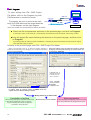
A3: Log
Program Log function working with “Program” button
“Program” button enables you to write program onto your target flash memory directly. This function
records a log file after the programming.
This function is disabled as a default setting. “Enable log” check box should be checked and OK
has to be pressed in order to use this log function for the first time.
Once this is enabled. You do not need to setup again from the next use.
Press “View Log” button to open log file on notepad.
Please be sure the appropriate file path for log file should be specified to use.
① Please click "Log" button to open setting
dialog "Program Log Settings".
②The log function is disabled as default setting.
Please check ③ on to enable it.
④Select the file you want to save the log into
⑤ Click “Browse” to select one.
②
③
④
⑥
⑤
⑥Please click "View Log" button to open log
file.
①
ID file that compiler makes is available for R8C,M16C,M32R,740 families.
You can specify each protect ID to fill each box. And you can fill them at once with loading ID file that a
compiler makes.
The format of ID file is not defined. Therefore there may be some ID file that cannot be read. This
function is confirmed to work with ID file that R8C compiler makes.
name of an ID file
Please specify a name of an ID file that was
made by compiler and press "Open" button to
activate ID settings.
FM-ONE
HOKUTO DENSHI CO;LTD; 株式会社
15
Using on Windows Vista and Windows 7.
Not the all functions of this product cannot be available on Windows Vista.
But “Save” and “Load” functions are available on Windows Vista.
You can make project files on Vista that enable this programmer to work as standalone.
“Program” and “Log” buttons are not shown on Vista.
Single wire programming at 1Mbps is supported
Programming at 250Kbps and 1Mbps are available with 20P-14P-convert board named ”20-14pin R8C
SINGLE WIRE FASTEST” ※. The target MCU has to be able to be programmed on single wire.
Please be sure that “Checksum” function as verify is not available on this programming way. So if you
choose this way when “Checksum” has been selected, “Byte” is automatically selected as verify.
※Please
refer to " About programming onto R8C・M16C・M32R series " and " Purchase of expendable supplies " for detail
about "20-14pin R8C single wire fastest".
16
FM-ONE
HOKUTO DENSHI CO;LTD; 株式会社
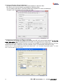
●Setting of Disk Cache.(WindowsXP)
This setting enables it to be quicker to transfer data into compact flash after pressing "Program" button.
("Safety device removing" has to be operated correctly on this setting without fail.)
1.
This should be set at "DeviceManager" dialog. Open
"ControlPanel" and press "System"
2.
Choose hardware tab and click "DeviceManager"
3.
Please find "HOKUTO CompactFlash I/F USB Device". It is
under "disk drive".
4.
Click "Policy" tab and choose down side of radio button and
click "OK" button.
That is all to setup.
FM-ONE
HOKUTO DENSHI CO;LTD; 株式会社
17
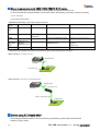
With the switch on FM-ONE【Offline】
How to write in using the switch on the FM-ONE body. Instead of connecting to the PC, writing in is done with the switch on
the body (Offline operation). As it can operate with batteries, it has a wider advantage, for example, maintenance is possible in
the field or it is used for evaluation at the client’s office.
B : Write switch (OK)
【Connection】
To write in, the equipment must be connected as a
diagram describes on the right. If the body is not
connected to PC, power cannot be supplied from the USB
bus. Prepare the attached AC adapter or specified
batteries. To start writing in, the target must also be
supplied with power.
Target board
Attached AC adapter
or batteries
Flash on-chip microcomputer FM-ONE
From CF to on-chip FlashROM
Offline operation
【advance preparation of a project file】
To make write in, the project file must be stored in advance in the CF put in the body.
【Writing procedure】
①
②
③
④
⑤
Connect the FM-ONE body with CF inserted in to
the target board, and power should be supplied with
first the body and next the target board.
The startup screen on the right (result of self-test) is
shown on the LCD of the FM-ONE body for about
three seconds.
If self-test is done properly, one of the project files
saved in the CF will be immediately displayed.
FM-ONE System
2.4V
Folder
DEF
Date
05/01/01
Time
00:00:00
When another project is to be selected, display the
desired project by using ↑↓up-down keys.
Start writing by pushing Write button.
Completion of writing is displayed as follows:
FM-ONE System
2.4V
user1 sum=00000000
user2 sum=00000000
Complete
Programming is continued by push the Write
button. In ending programming, please push the
Write button after cancel button or N is selected.
【The follow of programming】
①
②
YES
③
④
Starting System ・ ・ ・
Self test OK
version xxxxxxxx
Cancel
State of access is displayed
SET
Alteration of Parameter of the saved project.
①Display the project to be altered and push the SET button.
②Alter the items by pushing ↑↓keys, and select the desired item
from among items by pushing → ← keys, and alter the set value by
the ↑↓keys.
③Determine the content by pushing Write/OK button, and then reset
form the altered screen. (Access display lights once.)
If Cancel button is pushed instead of Write/OK, the set value is not
altered and resets.
Key operation
(Cancel)
The programming after the second by off-line
changed as shown in left figure.
Because the small file is taken into the memory at
the programming, Verify and Retry become
high-speed.
NO
Key operation (Write)
FM-ONE SYSTEM
[Exec DEFAULT.HDP ]
Starting boot mode.
Please wait ・・・・・・
FM-ONE SYSTEM
former flow
USB/DC
(Programming omission)
⑤
18
[Exec DEFAULT.HDP ]
user1 sum = xxxxxxxx
user2 sum = xxxxxxxx
complete. Again? Y / N
Write
Ok
※Screen display when AC adapter is used.
FM-ONE SYSTEM USB/DC
Folder
DEFAULT
Date
08/07/31
Time
16:00:00
Key operation (Write)
FM-ONE SYSTEM USB/DC
[Exec DEFAULT.HDP ]
Upon start-up, the results of self-test is displayed.
Key operation
(Write)
Key operation (Cancel)
FM-ONE
HOKUTO DENSHI CO;LTD; 株式会社
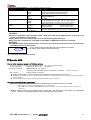
Parameters to be displayed ※ For detailed set values, refer to A1.
Page
Items
Set values
Communication setting
BOOT
Async
Sync
Pin
Vrify
FFskip
CLK MODE
XTAL
CKM
CKP
USER 1
USER 2
MCU
LANGUAGE
1200/2400/4800/9600/19200
1200/2400/4800/9600/19200/38400/76800*1
Pin setting & Option
Clock & Clock mode/CKM
CKP &
display
Program
names
MCU type & laubguage
*1 Set values more than selected rate are displayed.
NONE/10K/25K/50K/100K/250K/500K/1M/2M
FWE/MD0/MD1/IO0/IO1/IO2
NONE/CSUM/BYTE
YES/NO
(Value displayed when CF saved) Alter by up-down button*2
(Value displayed when CF saved) Alter by up-down button*2
(Value displayed when CF saved) Alter by up-down button*2
(Value displayed when CF saved) Alter by up-down button
HDU file displayed
Alter by up-down button
HDU file displayed
Alter by up-down button
(Selection displayed when CF saved)
(Selection displayed when CF saved)
Cannot select.
Alter by up-down button.
*2 Alteration is not possible by MCU.
CAUTION!
Project is displayed under the folder name. Note that if the wrong HDP file name is entered in the
folder, confirmation is not possible.
Don’t take out CF when Access lamp is on as saved data may be destroyed.
Don’t use the converted user’s file HDU on other MCU as ROM areas cannot be confirmed.
CAUTION!
If CANCEL button is pushed three times consecutively on the Project selection screen, functions other
than Write and Cancel are blocked.
A key symbol before a letter tells that switch operation is blocked.
FM-ONE System
2.4V
To unlock, push CANCEL button three times.
Folder
DEFAULT
Date
Time
05/01/01
00:00:00
This is a display of the body when blocked.
Specific MCU
How to write in external memory of ROMless articles
Writing is possible to external Flash ROM extended on the following ROMless MCU.
Corresponding MCU
H8SX/1650, H8SX/1651 or equivalents
Standard external ROM
MBM29LV800BA-70 (Fujitsu)
*TC58FVM5T2AFT-65(TOSHIBA),S29GL032M90TFIR4(SPANSION) finished the confirmation
Writing method
Normal writing is possible.
Writing control program to external memory differs depending on external memories to be use.
Contact us as needed on how to convert protocols different from the standard source, and we will explain according to
the specification.
For the target interface, refer to H8SX/1650 Material edition of User’s Manual.
What cannot be done with a special MCU.
Writing in H8/3664N Stack EEPROM varies depending on an external memory to be used.
*If writing is not done in Stack EEPROM, you can make FF skip.
FM-ONE dose not delete Stack EEPROM. FF skip is chosen, FF area remains the previous data, resulting in a
verify error.
When entering values into the target clock in H8S/2172F, enter the twice as the values of the populated
clock. Writing is not possible thorough clock synchronized communication.
FM-ONE
HOKUTO DENSHI CO;LTD; 株式会社
19
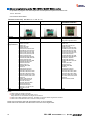
About programming onto R8C・M16C・M32R・R32C series
It’s possible to program onto devices(shown as below)with an optional conversion unit.
Format…MOT/HEX
new elements will be added.
【Outlines of each unit】(R8C/M16C Series,R8C Series)
Cable Name
20-10pin FOUSB
20-14pin R8C*1
Conversion unit
20<->10pin FOUSB
20<->14pin R8C
20-14pin R8C
SINGLEWIRE FASTEST*2
20<->14pin R8C SINGLE WIRE
Included
Specification
10pins straight cable is attached
Connecting to USB Writer and
M16C Flash Starter*3
14pins straight cable is attached
Connecting to Emulator E8a *4
14pins straight cable is attached
Connecting to Emulator E8a *4
Group of
supported MCU
R8C/10~13,
R8C/18,19,1A,1B
R8C/20~29
R8C/2A,2B,2C,2D
R8C/2E,2F,2K,2L
R8C/32A,32C,32D,32G,32H
R8C/32M,33A,33C,33D,33G
R8C/33H,33M,33T,34C,34E
R8C/34F,34G,34H,34K,34M
R8C/34P,34R,34U,34W,34X
R8C/34Y,34Z,35A,35C
R8C/35D,35M,36A,36E,36F
R8C/36G,36H,36M,36W,36X
R8C/36Y,36Z,38A,38C
R8C/38E,38F,38G,38H,38M
R8C/38W,38X,38Y,38Z
R8C/3GA,3GC,3GD
R8C/3JA,3JC,3JT
R8C/3MK,3MU,3MQ
R8C/36T-A
R8C/54E,54F,54G,54H
R8C/56E,56F,56G,56H
R8C/L35A,L35B,L35C,L35M
R8C/L36A,L36B,L36C,L36M
R8C/L38A,L38B,L38C,L38M
R8C/L3AA,L3AB,L3AC,L3AM
R8C/LA3A,LA5A,LA6A,LA8A
R8C/LAPS
R8C/M11A,M12A,M13B
M16C/26,26A,28,29,1N
M16C/30P,57,5M,5L
M16C/62P,62A,62N,62M
M16C/63,64,64A,65
M32C/83,84,85,86,87
R32C/111,116,118,120,121
R32C/152,153,156
R8C/10~13
Price
¥2,000
¥2,000
Writing with single wire serial
R8C/14~19,1A,1B
R8C/20~29
R8C/2A,2B,2C,2D,2H,2J
R8C/2E,2F,2K,2L
R8C/32A,32C,32D,32G,32H,
R8C/32M,33A,33C,33D,33G,
R8C/33H,33M,33T,34C,34E
R8C/34F,34G,34H,34K,34M
R8C/34P,34R,34U,34W,34X
R8C/34Y,34Z,35A,35C
R8C/35D,35M,36A,36C,36E
R8C/36F,36G,36H,36M,36W
R8C/36X,36Y,36Z,38A
R8C/38C,38E,38F,38G
R8C/38H,38M,38W,38X,38Y
R8C/38Z
R8C/3GA,3GC,3GD
R8C/3JA,3JC,3JT
R8C/3MK,3MU,3MQ
R8C/36T-A
R8C/54E,54F,54G,54H
R8C/56E,56F,56G,56H
R8C/L35A,L35B,L35C,L35M
R8C/L36A,L36B,L36C,L36M
R8C/L38A,L38B,L38C,L38M
R8C/L3AA,L3AB,L3AC,L3AM
R8C/ LA3A,LA5A,LA6A,LA8A
R8C/LAPS
R8C/M11A,M12A,M13B
¥5,000
Notes:
*1 Please output TX and RX to program.
*2 Project File Maker needs to be newer than 1.0.0.4.
Verify-checksum is not available with single wire connection.
*3 Please refer to MCU hardware manual for examples of connection Serial Programmer and MCU.
*4 Please refer to “E8a Emulator user’s manual” for this pin assign.
Please use programming tools with appropriate version of control software.
Please refer to the instruction manual for each connection on the target board.
20
FM-ONE
HOKUTO DENSHI CO;LTD; 株式会社
【Outlines of each unit】(M16C Series)
Cable Name
20-14pin M16C
Conversion
unit
20<->14pin M16C
20-14pin M16C SINGLEWIRE
AS*2
20<->14pin M16C
Included
Specification
14pins straight cable is attached
Connecting to Emulator E8a*4
14pins straight cable is attached
Connecting to Emulator E8a*4
14pins straight cable is attached
Connecting to Emulator E8a*4
Writing with asynchronous
communication.(single wire)
M16C/63,64,64A,57,5M,5L,65
Writing with synchronous
communication.(single wire)
M16C/63,64,64A,57,5M,5L,65
¥5,000
¥5,000
Group of
supported
MCU
M16C/26,26A,28,29,1N
M16C/30P,57,5M,5L
M16C/62P,62A,62N,62M
M16C/63,64,64A,65
M32C/83,84,85,86,87
Price
¥2,000
【Outlines of each unit】(RX,740 Series)
Cable Name
20-14pin RX
20-14pin M16C SINGLEWIRE
BS*2
20<->14pin M16C
20-14pin 740
Conversion unit
20<->14pin RX
20<->14pin 740
Included
Specification
Group of
supported MCU
14pins straight cable is attached
Connecting to Emulator E1 and E20*5
RX111
RX210,21A,220
RX621,62N,62T,62G
RX630,631,63T
14pins straight cable is attached
Connecting to Emulator E8a *4
740/3803,38D5
Price
¥2,000
¥2,000
Notes:
*2 Project File Maker needs to be newer than 1.0.0.4.
Verify-checksum is not available with single wire connection.
*4 Please refer to “E8a Emulator user’s manual” for this pin assign.
*5 Please refer to “E1 Emulator user’s manual” or “E20 Emulator user’s manual” for this pin assign.
Please use programming tools with appropriate version of control software.
Please refer to the instruction manual for each connection on the target board.
how to connect
Attached cable
FM-ONE
10pins or 14pins cable
Conversion unit
Target board
10-14P conversion connector
(TOE8)
Some of the boards needs attached
10-14P conversion connector.
FM-ONE
HOKUTO DENSHI CO;LTD; 株式会社
21
About programming onto V850・78K0・78K0R・RL78 series
It’s possible to program onto devices(shown as below)with an optional conversion unit.
In connecting with the recommendation circuit of each series, the following conversion units are necessary.
Format…MOT/HEX
new elements will be added.
【Outlines of each unit】(V850,78KO,78K0R,RL78Series)
Cable
20-16pin V850
20-16pin 78K0
20-16pin 78K0R SINGLE WIRE 20-14pin RL78 SINGLE WIRE
Name
20<->16pin 78K0R SINGLE WIRE 20<->14pin RL78 SINGLE WIRE
Conversion 20<->16pin V850 20<->16pin 78K0
unit
Included
-
16pins straight cable
is attached
16pins straight cable is attached
14pins straight cable is attached
Usage
-
-
Connecting to E1 or E20 emulator *2
Group of
supported
MCU
V850ES/Jx2,Jx3-L
V850E/Ix3
V850E2/Mx4,Sx4-H
78K0/Kx2
Connecting to QB-MINI2 connector
*1
78K0R/Kx3
V850E2/Mx4,Sx4-H
Price
¥2,000
¥5,000
¥5,000
RL78/G10, G12,G13,G14,G1A,G1C
RL78/I1A
RL78/L12,L13
¥5,000
*1 Please refer to “QB-MINI2 user’s manual” for this pin assignment to each MCU.
*2 Please refer to “E1 emulator user’s manual” or “E20 user’s manual” for this pin assignament for each MCU.
how to connect (conversion unit only)
Attached cable
FM-ONE
Target board
Conversion unit
how to connect (with 16pin or 14pin straight cable)
Attached cable
FM-ONE
Conversion unit
16pin or 14pin cable
Target board
Before using RL78 family MCU
If the setting prohibited number is set at the option byte (000C2H), programming would be failed.
Please try again if failed.
22
FM-ONE
HOKUTO DENSHI CO;LTD; 株式会社
Troubleshooting
Items to be confirmed at errors
State of Cable & Power supply
While operating, there may be a loose connection or breaking, so confirm if the cable is properly connected. Also, when the
FM-ONE body is turned OFF, or some trouble occurs while operation in MCU, make sure that power is properly supplied to the
body and the board. In particular, when using the system with batteries, be sure to replace with new ones in case they drain.
Maximum length of the attachment of the target table is 30cm and if it is too long, it may result in a harmful effect.
Setting of transmission rate
Transmission rate varies depending on the target board clock. For the transmission rates, refer to the ROM chapter of the
Hardware Manual. Transmission by the writing control program, or User program with a built-in ROM deleted, the maximum
transmission rate must be set considering the serial communication error rate. The communication error rate should be
adjusted by changing the combinations of rates. (For selectable rates, refer to the Bit rate register section of the Serial
Communication chapter, the Hardware Manual.)
Various types of setting
Confirm how MCU selection and Pin setting are done. When this system is used by reinstalling or in a different
environment, the pin setting may remain the default value and the boot mode does not start readily. For detailed pin
setting, refer to the Boot mode timing chart section.
State of MCU
The more the frequency of writing becomes, the more frequency of delete and retry of program writing becomes, and
consequently time required for writing is longer. When a socket is applied to the target, be sure that there is no loose
connection.
Target circuit
On the assumption of Open Collector drive, RESET is output from FM-ONE. A delayed or slow output causes a startup error.
The description of the main body and points to remember of the reference circuit diagram are shown in the beginning of the
User’s guide of the User’s Manual. Read them when examining output waveform.
Programs
Make sure whether reduplicated addresses are in the MOT/HEX file or not, or writing is designated at any area other than
built-in ROM area. Bear in mind that file extension is possible only on .MOT/HEX file and make sure file formats as well.
FM-ONE
HOKUTO DENSHI CO;LTD; 株式会社
23
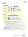
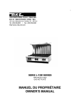
Timing Chart
Timing chart of pins connected to the target interface is as follows:
On start-up in Boot mode
約 500msec
1
RESET
(Open collector)
H
H
L
約 250msec
3
9
約 500msec
*2
FWE・5MD0・7MD1
I/O0・11I/O1・13I/O2
Determined level(H・L・Hi-Z)
Hi-Z
Transmission data to
RXD pin
(17TXD)
H output of “00”
H
Hi-Z
*1
L
*1・・・ Maximum frequency of “00” output is 512 times and continue transmitting until a reply from the target(15RXD)
Even “00” output is done 512 times when there is no reply, an error occurs.
*2・・・ Only R8C Tiny series MCU is 100msec.
Boot mode ends
約 250msec
1
RESET
(Open collector)
*2
約 250msec
H
*2
H
L
3
9
FWE・5MD0・7MD1
I/O0・11I/O1・13I/O2
Transmission data to
RXD pin
(17TXD)
Hi-Z
Hi-Z
*2・・・ Only R8C Tiny series MCU is 100msec.
Don’t select the same MOT/HEX file in the normal area file and secondary area file.
If the same name is used, even another file, HDU file is overwritten when the original file, HDU format is converted
(If this mistake is made, our FM-ONE Project File Maker issues a warning message).
As many as 10 file folders in the CF can be perceived by FM-ONE.
If more than 10 file folders are in the CF root, FM-ONE will detected 10 files voluntarily and display them on LCD
screen. The order of display cannot be designated.
Files other than the project can be placed in the CF, it is recommended that such files be packed into a single
folder to avoid trouble of confirming unnecessary files as circumstances permit.
When files other than the project are placed in the CF, we don’t recommend that too many files be not placed as
file checking is troublesome.(Unless the folder is selected as a project, file checking is not done inside. If that
folder is selected by mistake, we will not guarantee.
Project is displayed under the folder name. Make sure that files with different names are not put in the
folder as it cannot be confirmed.
While the access lamp is on, never take out the CF as saved data may be destroyed.
If CANCEL button is pushed three times consecutively of the Project selection screen, functions other than
Write and Cancel are locked.
Don’t use the converted user File HDU on another MCU because ROM areas cannot be confirmed.
24
FM-ONE
HOKUTO DENSHI CO;LTD; 株式会社
Errors while writing
Input VCC to 20pin of target I/F
ターゲットカラノデンゲンガニュウリョクサレ No power supply from target
テイマセン
ビットレートチョウセイシュウリョウノ00ガジ No 00 replyed from target at rate adjust
ュシンデキマセン
55ソウシンゴノAAガジュシンデキマセン No AA replyed from target after 55 sent
55ソウシンゴニAAイガイガジュシンサレマ Instead of AA other reply backed for 55
シタ
Failed at erasing flash memory
イレースニシッパイシマシタ
Correct response did not back from TGP
TGPガドウサシテイマセン
Wrong reply was received from TGP
TGPガイジョウデス
Failed at serial communication parameter
シリアルノセッテイニシッパイシマシタ
55ソウシンゴノE6ガジュシンデキマセン E6 did not back as reply for 55
55ソンシンゴニE6イガイガジュシンサレマ Wrong reply backed to E6 after sending 55
シタ
ニュウリョクサレタビットレートガセンタクデ Input value for bitrate is wrong to use
キマセン
ビットレートセッテイゴノACKガジュシンデ Failed to get recept for bitrate setting
キマセン
ブートモードキドウジニRXDタンシガLOW RXD port stays low in bootmode starting
ノママデシタ
ブートモードキドウジニRXDタンシガHIGH RXD port stays high in bootmode starting
ノママデシタ
TGWカキコミアドレスガセッテイデキマセ Failed to set programming address of TGW
ン
カキコミエラーガハッセイシマシタ
ビットレートセンタクゴノカクニンコードガジ
ュシンデキマセン
バイトベリフェイエラーデス
Other errors
Programming error occured
File system error
Resulting from obtaining a file (folder) list from the
Root
Card not inserted
Can't open INI file
With formatted CF, a file is not found to save
system setting, or other errors
INI put error
Can’t load from a file to save system setting
Can’t write in a file to save system setting
CURFILE not found
An early-selected file set in the system is not in the
CF.
Can't open HDP file
Project file absent, name of folder is different from
that of project file, or other errors
HDP get error
Can’t load from project file.
Can't open HDH file
File of host program absent, or different one found
other than host program setup in the project
HDH illegal version
Something is wrong with version information of
host program
Can’t load from file of host program
HDH get error
HDH check sum error
File not found
Self test NG
FM-ONE
Possibly, incorrect pin setting or too quick a
communication rate during boot start-up.
Confirm the pin setting and communication rate as
well.
Possibly, too quick a maximum asynchronous
communication rate.Confirm the above rate.
Possibly, communication pin is not connected
properly in the circuit. Confirm connection.
Possibly, too quick amaximum asynchronous
communication rate/a synchronous communication
rate.Confirm the above rates.
Please reconfirm connection and setting contents.
Disagreement found in verifying
Resulting from other than FAT12/16/other errors
INI get error
Possibly, due to wrong MCU selection, or MCU
built-in FLASH memory is broken. Reconfirm
selected MCU model name.
Confirmation code cannot be
received
Please format a card
Please insert a card
Possibly, incorrect pin setting or too quick a
communication rate during boot start-up. Confirm
the pin setting and communication rate as well.
An adjustment error. Confirm the pin setting and
communication rates.
When file of host program is loaded and sum is
calculated, the sum is different from that of the file
pin
No file (folder) to write in is found.
It is reported that the result of selftest is NG.
HOKUTO DENSHI CO;LTD; 株式会社
Possibly due to broken file, inappropriate format or broken
CF. Try to recover by checking disk, save or format again.
Don’t select FAT32 when formatting CF.
File may be broken, inappropriate format, or CF broken.
Try to recover by checking disk, save or format again.
Insert CF of FAT12/FAT16 into the body.
Can move forward by pushing either button. When writing,
modifying set-up, or making keylock, a file to save system
setting is produced, and no error message occurs from
then on. There are maybe damaged files, inappropriate
format, or broken CF. Check the disk, save and format
again.
Possibly due to damaged file, inappropriate format, or
broken CF. Try to check the disk, save and format again.
Can move forward by pushing either button. Writing or
modifying set-up updates and improves files to save
system setting.
Confirm file name. Possibly due to damaged file,
inappropriate format, or broken CF. Try to check the disk,
save and format again.
Possibly due to damaged file, inappropriate format, or
broken CF. Try to check the disk, save and format again.
Host program is found but error messages are displayed.
Possibly due to damaged file, inappropriate format, or
broken CF. Try to check the disk, save and format again.
Possibly due to damaged file, inappropriate format, or
broken CF. Try to check the disk, save and format again.
Transmit data by USB connection, or save data by
over-the-counter CF reader and then insert file into
FM-ONE.
Please set the switch (for farmware update) to
normal position and
reconnect.
note: please refer to page3 for details.
25
Correspondence MCU
Please refer to “The list of supported flash memory MCU” (PDF) recorded on the provided CD for
what MCU FM-ONE supports.
Version upgrade method
Version upgrade as follows:
※Serial number of the body confirmed when it was upgraded.
Version upgrade
Price
Remarks
Windows2000,
Windows
XP(Professional/Home Edition) , Windows Vista, Windows
FM-ONE
¥6,000
7 and Windows8.1 Japanese environment.
Version upgrade
※ Contact us to use FM-ONE in another environment.
software
※Price is subject to change. For the latest information, visit our website.
Optional items
The followings are the optional items for FM-ONE.
Name
OE conversion cable(20⇒14P)
Price
\2,000
Remarks
20-10pin FoUSB
\2,000
A conversion unit for R8C/M16C and a 10pins target cable.
20-14pin R8C
\2,000
A conversion unit for R8C and a 14pins target cable.
20-14pin R8C
SINGLE WIRE FASTEST
\5,000
A conversion unit for R8C and a 14pins target cable.
※For single wire connection only.
20-14pin M16C
\2,000
A conversion unit for R16C and a 14pins target cable.
\5,000
A conversion unit for R16C and a 14pins target cable.
※For single wire connection only.
Asynchronous communication.
A conversion unit for R16C and a 14pins target cable.
※For single wire connection only.
Synchronous communication.
20-14pin M16C SINGLE WIRE AS
20-14pin M16C SINGLE WIRE BS
\5,000
Conversion board for OE I/F write-in,14target cable.
20-14pin RX
\2,000
A conversion unit for RX and a 14pins target cable.
20-14pin 740
\2,000
A conversion unit for 740 and a 14pins target cable.
20-14pin RL78 SINGLE WIRE
\5,000
A conversion unit for RL78 and a 14pins target cable.
※For single wire connection only.
20-16pin V850
\2,000
A conversion unit for V850.
20-16pin 78K0
\5,000
A conversion unit for 78K0 and a 16pins target cable.
A Common conversion unit for 78K0R and RL78, and 16pins
target cable.
※For single wire connection only.
A Common conversion unit for 78K0R and RL78, and 16pins
\5,000
target cable.
20-16pin 78K0R SINGLE WIRE
※For single wire connection only.
※Price is subject to change. For the latest information, visit our website.
20-16pin 78K0R SINGLE WIRE
26
\5,000
FM-ONE
HOKUTO DENSHI CO;LTD; 株式会社
Includes
These includes are purchasable.
Expendables supplies
AC adapter
Price
\2,500
FM-ONE Target cable (20P)
\1,000
Remarks
The provided AC adapter is verified for Japanese domestic
use only.
Free shipping for orders over 10 unites or more.
\6,000
Please purchase version up software.
※Applicable for both FLASHMATE5V1 and FLASH2
CD
Guarantees operation when using FM-ONE.
CF card "CF115-1G"
\5,000
(made by I-O Data Device, Inc.)
※Price is subject to change. For the latest information, visit our website.
FM-ONE User’s Manual
© 2005-2014 北斗電子 Printed in Japan First printing: January 19, 2005
REV.2.0.0.0(140411)
Published by Hokuto Denshi Co., Ltd. 株式会社
3-7, Odori-nishi 16, Chuoku Sapporo Hokkaido, 060-0042, Japan
phone +81-011-640-8800
fax +81-011-640-8801
e-mail:[email protected] (Technical support), [email protected] (Order and inquiries)
URL: http://www.hokutodenshi.co.jp
FM-ONE
HOKUTO DENSHI CO;LTD; 株式会社
27