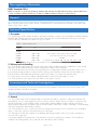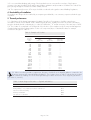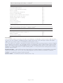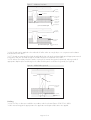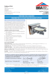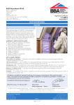
1
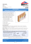
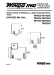
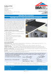
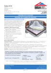
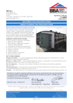
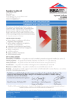
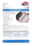
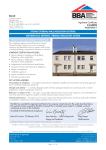
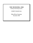
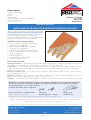
APPROVAL INSPECTION TESTING CERTIFICATION Celotex Limited Lady Lane Industrial Estate Hadleigh Ipswich Suffolk IP7 6BA Tel: 01473 822093 Fax: 01473 820880 TECHNICAL APPROVALS FOR CONSTRUCTION Agrément Certificate 95/3197 e-mail: [email protected] website: www.celotex.co.uk Product Sheet 3 CELOTEX INSULATION CELOTEX RANGE OF PIR INSULATION BOARDS FOR PITCHED ROOF INSULATION PRODUCT SCOPE AND SUMMARY OF CERTIFICATE This Certificate relates to the Celotex Range of PIR Insulation Boards for Pitched Roof Insulation, comprising rigid polyisocyanurate foam boards with low emissivity aluminium foil facings on both sides, for use in pitched roofs. AGRÉMENT CERTIFICATION INCLUDES: • factors relating to compliance with Building Regulations where applicable • factors relating to additional non-regulatory information where applicable • independently verified technical specification • assessment criteria and technical investigations • design considerations • installation guidance • regular surveillance of production • formal three-yearly review. KEY FACTORS ASSESSED Thermal performance — the manufacturer’s declared thermal conductivity (90/90 value) of the insulation component of the products, as declared by the Certificate holder, is 0.022 W·m–1·K–1 (see section 5). Condensation — the foil facings have a water vapour resistance exceeding 70 MN·s·g–1 and the insulation core has a water vapour resistivity of 300 MN·s·g–1m–1 and, therefore, will provide a significant resistance to water vapour transmission (see section 6). Behaviour in relation to fire — the products will not contribute to the development stages of a fire or present a smoke or toxic hazard (see section 7). Resistance to moisture — the products will not be adversely affected by rain showers during installation, nor by winddriven snow or rain penetrating the tiling in service (see section 10). Durability — the product will have a life equivalent to that of the roof structure in which it is incorporated (see section 12). The BBA has awarded this Agrément Certificate to the company named above for the products described herein. These products have been assessed by the BBA as being fit for their intended use provided they are installed, used and maintained as set out in this Certificate. On behalf of the British Board of Agrément Date of Second issue: 12 October 2010 Chris Hunt Greg Cooper Originally certificated on 31 March 1996 Head of Approvals — Physics Chief Executive Certificate amended on 3 November 2010 with updated information in the Thermal performance section. The BBA is a UKAS accredited certification body — Number 113. The schedule of the current scope of accreditation for product certification is available in pdf format via the UKAS link on the BBA website at www.bbacerts.co.uk Readers are advised to check the validity and latest issue number of this Agrément Certificate by either referring to the BBA website or contacting the BBA direct. British Board of Agrément Bucknalls Lane Garston, Watford Herts WD25 9BA ©2010 Page 1 of 12 tel: 01923 665300 fax: 01923 665301 e-mail: [email protected] website: www.bbacerts.co.uk Regulations In the opinion of the BBA, the Celotex Range of PIR Insulation Boards for Pitched Roof Insulation, if used in accordance with the provisions of this Certificate, will meet or contribute to meeting the relevant requirements of the following Building Regulations: The Building Regulations 2010 (England and Wales) Requirement: C2(c) Resistance to moisture Comment: The products can enable or contribute to enabling a roof to meet this Requirement. See sections 6.1 and 6.5 of this Certificate. Requirement: L1(a)(i) Conservation of fuel and power Comment: Requirement: Regulation 7 Materials and workmanship Comment: The products are acceptable. See section 12 and the Installation part of this Certificate. The products can contribute to meeting this Requirement. See sections 5.3 to 5.6 of this Certificate. The Building (Scotland) Regulations 2004 (as amended) Regulation: 8(1) Regulation: Standard: 9 3.15 6.1(b) 6.2 Carbon dioxide emissions Building insulation envelope The products can contribute to satisfying clauses, or parts of 6.1.1(1), 6.1.2(2), 6.1.6(1), 6.2.1(1)(2), 6.2.3(1), 6.2.4(1)(2), 6.2.5(1)(2) and 6.2.6(2) of these Standards. See sections 5.3 to 5.6 of this Certificate. Comment: Regulation: Building standards – construction Condensation When used in conjunction with an appropriate vapour control layer, the products will be unrestricted under this Standard, with reference to clauses 3.15.1(1)(2) and 3.15.4(1)(2). See sections 6.1 and 6.6 of this Certificate. Comment: Standard: Standard: Fitness and durability of materials and workmanship The products can contribute to a construction meeting this Regulation. See section 12 and the Installation part of this Certificate. Comment: 12 Building standards – conversions All comments given for these products under Regulation 9, also apply to this Regulation, with reference to clause 0.12.1(1) and Schedule 6(1). Comment: (1) Technical Handbook (Domestic). (2) Technical Handbook (Non-Domestic). The Building Regulations (Northern Ireland) 2000 (as amended) Regulation: B2 Fitness of materials and workmanship Comment: Regulation: C5 Condensation Comment: Regulation: F2(a)(i) Conservation measures The products are acceptable. See section 12 and the Installation part of this Certificate. Roofs incorporating the products can meet this Regulation. See section 6.1 of this Certificate. Roofs incorporating the products can satisfy or contribute to satisfying this Regulation. See sections 5.3 to 5.6 of this Certificate. Comment: Regulation: Comment: F3(2) Target carbon dioxide Emission Rate Roofs incorporating the products can satisfy or contribute to satisfying this Regulation. See section 5.3 of this Certificate. Construction (Design and Management) Regulations 2007 Construction (Design and Management) Regulations (Northern Ireland) 2007 Information in this Certificate may assist the client, CDM co-ordinator, designer and contractors to address their obligation under these Regulations. See section: 13 General (13.2) of this Certificate. Page 2 of 12 Non-regulatory Information NHBC Standards 2010 NHBC accepts the use of the Celotex Range of PIR Insulation Boards for Pitched Roof Insulation, when installed and used in accordance with this Certificate, in relation to NHBC Standards, Chapter 7.2 Pitched roofs. General This Certificate relates to the Celotex Range of PIR Insulation Boards for Pitched Roof Insulation for use as insulation above, between and/or below rafters in tiled or slated pitched roofs designed and constructed in accordance with Clauses of BS 5534 : 2003. Technical Specification 1 Description The Celotex Range of PIR Insulation Boards for Pitched Roof Insulation comprises Celotex TB4000, GA4000, XR4000, GX4000 and FR4000, rigid polyisocyanurate foam board with low emissivity aluminium foil facings on both sides. These products are available in the dimensions given in Table 1. Table 1 Nominal dimensions Size (mm) Product Thickness (mm) TB4000 1200 x 2400 12, 20, 25, 30, 35, 40 and 45 GA4000 1200 x 2400 50, 55, 60, 65, 70, 75, 80, 85, 90, 95 and 100 XR4000 1200 x 2400 110, 120, 130, 140, 150, 165 and 200 GX4000 1200 x 600 FR4000 1200 x 2400 20–200 25, 50, 60, 70, 75, 80, 90, 100, 110, 120, 130, 140 and 150 2 Delivery and site handling 2.1 The boards are delivered to site in packs. Each pack contains a label bearing the manufacturer’s name, board dimensions and the BBA identification mark incorporating the number of this Certificate. 2.2 The boards must be protected from prolonged exposure to sunlight and should be stored either under cover or protected with opaque polythene sheeting. Where possible, packs should be stored inside. If stored outside, the boards should be stacked flat and raised above ground level, and not in contact with ground moisture. 2.3 Care must be exercised in handling individual boards to avoid crushing the edges or corners. 2.4 The boards must not be exposed to open flame or other ignition sources. Assessment and Technical Investigations The following is a summary of the assessment and technical investigations carried out on the Celotex Range of PIR Insulation Boards for Pitched Roof Insulation. Design Considerations 3 General 3.1 The Celotex Range of PIR Insulation Boards for Pitched Roof Insulation is effective in reducing U value (thermal transmittance) of new or existing pitched roofs for use above, between and/or below roof rafters in conjunction with internal lining board, roof tile underlay, timber counter battens and tiling battens in tiled or slated, pitched roofs, designed and constructed in accordance with the relevant Clauses of BS 5534 : 2003 for dwellings or other buildings with similar temperature and humidity conditions. 3.2 The boards are for use in constructions where the ceiling follows the pitch of the roof and encloses a habitable space, or where the ceiling is horizontal and encloses a loft space. 3.3 Although the boards will contribute to the buckling and racking strengths of the roof, normal cross-bracing is necessary when using them. 3.4 During installation the boards must not be walked on except over supporting roof timbers. The boards have insufficient nail holding ability to be considered as an alternative to timber sarking. Page 3 of 12 3.5 It is essential that detailing and jointing of the boards achieves a convection-free envelope of high vapour resistance. Any gaps should be filled, and/or taped. Ridges, abutments and penetrations should also be sealed. Flue pipes passing through the insulation should be suitably sleeved. 3.6 The requirements/provisions of fire stops should be considered with regard to national Building Regulations. 4 Practicability of installation The products are designed to be installed by a competent general builder, or a contractor, experienced with this type of product. 5 Thermal performance 5.1 Calculations of the thermal transmittance (U value) of specific roof constructions should be carried out in accordance with BS EN ISO 6946 : 2007 and BRE Report (BR 443 : 2006) Conventions for U-value calculations, using the declared thermal conductivity (λ90/90 value) of 0.022 W·m–1·K–1 and an emissivity of the outer layer of 0.05. 5.2 The U value of a completed roof will depend on the thickness of the insulation used, the extent and arrangement of timber bridging and the insulating value of other roof components/layers. Calculated U values for example constructions are given in Table 2. Table 2 Example roof U values U value Insulation thickness (mm) Over rafters (W·m–2·K–1) Between rafters (W·m–2·K–1) Between and under rafters (W·m–2·K–1) 12 30 50 70 90 100 120 150 165 200 40+45 50+45 50+50 60+65 70+70 75+75 80+40 100+25 120+25 100+65 0.57 0.39 0.29 0.23 0.19 0.17 0.15 0.12 0.11 0.10 — — — — — — — — — — 0.83 0.55 0.40 0.32 0.27 0.25 0.21 0.18 0.16 0.14 — — — — — — — — — — — — — — — — — — — — 0.25 0.28 0.22 0.18 0.16 0.15 0.20 0.20 0.17 0.19 5.3 When considering insulation requirements, designers should refer to the detailed guidance contained in the documents supporting the national Building Regulations. The U values shown in Table 3 indicate that the product can contribute to enabling a roof to achieve typical design U values referred to in those supporting documents (see Tables 3, 4 and 5). Table 3 Mean design roof U values — England and Wales (1) Construction U value (W·m–2·K–1) Notional dwelling 0.16 Existing building — new, replaced, renovated or retained roof 0.18 Notional non-domestic building 0.18 Dwelling new-build limit 0.20 Non-domestic new build limit 0.25 (1) Flexible approaches on existing buildings are given in the Approved Documents. Page 4 of 12 Table 4 Mean design roof U values — Scotland (1) Construction U value (W·m–2·K–1) Notional dwelling 0.13 New dwelling simplified method 0.13 Conversion of unheated building (into dwelling) 0.15 Extension to dwelling 0.15 New non-dwellings limit for shell and fit out 0.15 Conversion of unheated building 0.15 Non-domestic extension, alterations and reconstructions 0.15 Alterations and reconstructions to an element 0.18 Stand-alone building <50 m2 to a dwelling 0.18 New dwelling limit 0.18 New non-domestic limit 0.20 Conversion of heated building 0.25 Notional non-dwelling 0.25 (1) Flexible approaches on existing buildings are given in the Technical Handbooks. Table 5 Mean design roof U values — Northern Ireland (1) Construction U value (W·m–2·K–1) Notional dwelling 0.16 Existing building, replaced, renovated or retained roof 0.20 Building new-build limit 0.25 Notional non-domestic building 0.25 (1) Flexible approaches on existing buildings are given in the Technical Booklets. New buildings 5.4 Roofs with U values lower than (or the same as, for dwellings in Scotland) the relevant ‘notional’ value specified in section 5.3 will contribute to a building meeting its Target Emission Rate. Roofs with higher U values will require additional energy saving measures in the building envelope and/or services. 5.5 The products can contribute to maintaining continuity of thermal insulation at junctions between elements. Example junction details shown in Figure 1 are acceptable and the corresponding psi values in BRE Information Paper IP1/06 Table 3 Assessing the effects of thermal bridging at junctions and around openings, may be used in carbon emission calculations in Scotland and Northern Ireland. Detailed guidance on other junctions and on limiting heat loss and air infiltration can be found in: England and Wales — Approved Documents to Part L and for new thermal elements to existing buildings, Accredited Construction Details (version 1.0). See also SAP 2009 Appendix K and the iSBEM User Manual for new-build. Scotland — Accredited Construction Details (Scotland) Northern Ireland — Accredited Construction Details (version 1.0). Page 5 of 12 Figure 1 Junctions between roofs and walls breather membrane low emissivity air space Celotex PIR insulation below rafter Celotex PIR insulation between rafter void filled with insulation meeting an R-value of 2 1.2 m KW Celotex PIR cavity wall insulation Existing buildings 5.6 For existing buildings, in work such as extensions and conversions, roofs will be acceptable where they do not exceed the relevant U values given in section 5.3, and junctions and openings comply with section 5.6 or BRE Report (BR 262 : 2002) Thermal insulation: avoiding risks. 6 Condensation Interstitial condensation 6.1 Roofs will adequately limit the risk of interstitial condensation when they are designed and constructed in accordance with BS 5250 : 2002, Section 8.4 and Appendix D. 6.2 The risk of interstitial condensation will be minimal under normal conditions of use. The foil facings have a water vapour resistance exceeding 70 MN·s·g–1 and the insulation core has a water vapour resistivity of 300 MN·s·g–1m–1 and, when installed with tightly butted joints, filled/sealed gaps and joints, will provide a continuous convection-free envelope of high vapour resistance. Therefore, a suitable vapour-permeable, roof tile underlay may be laid over the insulation boards without ventilated air space. When using a high resistance (type HR) underlay, the space below it must be ventilated in accordance with BS 5250 : 2002, Section 8.4. 6.3 Where the product is installed in a roof with either a horizontal or sloping ceiling (ie room-in-the-roof), a ‘warm roof’ space is created and ventilation is not required. However, any insulation in a horizontal ceiling should be removed. 6.4 Where high humidity may be expected, a vapour control layer should also be used unless a condensation risk analysis in accordance with BS 5250 : 2002 shows that it is not necessary. Surface condensation 6.5 Roofs will adequately limit the risk of surface condensation when the thermal transmittance (U value) does not exceed 0.35 W·m–2·K–1 at any point and the junctions with walls are designed in accordance with the relevant requirements of Limiting thermal bridging and air leakage : Robust construction details for dwellings and similar buildings, TSO 2002 or BRE Information Paper IP 1/06 Assessing the effects of thermal bridging at junctions and around openings. 6.6 Roofs will adequately limit the risk of surface condensation when the thermal transmittance (U value) does not exceed 1.2 W·m–2·K–1 at any point. Guidance may by obtained from BS 5250 : 2002, Section 8, and BRE Report (BR 262 : 2002). 7 Behaviour in relation to fire 7.1 When installed between, under or over rafters the product will be contained between the roof and internal lining board until one is destroyed. Therefore, the insulation will not contribute to the development stages of a fire or present a smoke or toxic hazard. Page 6 of 12 7.2 The product must not be carried over junctions between roofs and walls required to provide a minimum period of fire resistance. The continuity of fire resistance must be maintained, for example as described in: England and Wales — Approved Document B, Volume 1 Dwelling houses, paragraphs 5.11 and 5.12. Approved Document B, Volume 2 Buildings other than dwelling houses, Diagram 30. Scotland — Mandatory Standard 2.2, clauses 2.2.7(2) and 2.2.10(1) (1) Technical Handbook (Domestic). (2) Technical Handbook (Non-Domestic). Northern Ireland — Technical Booklet E, paragraph 3.21. 7.3 The boards may be classified as shown in Table 6. Table 6 Fire classification TB4000 GA4000 XR4000 GX4000 FR4000 Class 1 to BS 476-7 (20–90 mm only) Class 1 to BS 476-7 Class 1 to BS 476-7 (50–90 mm only) Euroclass F to BS EN 13501-1 Euroclass D to BS EN 13501-1 (55–90 mm) Class 1 to BS 476-7 Euroclass F to BS EN 13501-1 (20–50 mm and 95–200 mm) Euroclass F to BS EN 13501-1 Euroclass D to BS EN 13501-1 (55–90 mm) Pass to BS 476-6 Euroclass F to BS EN 13501-1 (50 mm, 95 mm and 100 mm) Class 0 as described in the national Building Regulations 8 Strength The products, when installed in accordance with the Certificate holder’s instructions and this Certificate, will resist the normal loads likely to be met during installation and in service. 9 Structural stability 9.1 Wind uplift will depend largely on the building geometry and its geographical location and should be calculated in accordance with BS 6399-2 : 1997. Snow loadings should be calculated in accordance with BS 6399-3 : 1988. 9.2 When calculating the fixing spacing required to resist the calculated loadings, the requirements of BS EN 1995-1-1 : 2004 and the National Annex, should be followed where possible. Further guidance can be obtained from the Certificate holder. The Certificate holder and fixing manufacture must advise on the use of the correct proprietary fixings and improved nails and fixing capacity in accordance with BS EN 1995-1-1 : 2004 and the National Annex. 10 Resistance to moisture The products will not be adversely affected by rain during installation, nor by wind-driven snow or rain penetrating the tiling in service. Water absorption is low and its influence on the λ value is minimal. 11 Maintenance As the products are confined within the pitched roof by the overlay and it has suitable durability (see section 12), maintenance is not required. 12 Durability The products will have a life equivalent to that of the roof structure in which they are incorporated. Installation 13 General 13.1 Installation of the Celotex Range of PIR Insulation Boards for Pitched Roof Insulation must be in accordance with the relevant Clauses of BS 5534 : 2003 and the manufacturer’s instructions, and can be carried out in all conditions normal to roof work. Page 7 of 12 13.2 The boards are light to handle but some handling difficulties may be experienced in windy conditions. Once laid the boards will not support the weight of operatives. Appropriate care must be taken during installation and tiling. 13.3 The boards can be cut easily but care must be taken to prevent damage particularly to edges. Damaged boards should not be used. Small areas of damaged facer may be repaired with self-adhesive aluminium foil tape. 13.4 It is important to fill/seal gaps and joints in the insulation envelope. 13.5 Roof tiles or slates are installed in accordance with the relevant Clauses of BS 5534 : 2003. 13.6 When applying roof tiles or slates to a warm roof construction, the recommendations of the manufacturer should be followed. 14 Procedure 14.1 A treated-timber stop batten, equal in thickness to the insulation board, is fixed at eaves level and the boards butted directly against it (see Figure 2). Figure 2 Over-rafter insulation rafter counter batten roof tile underlay Celotex PIR insulation (over rafter) aluminium foil tape treated timber stop batten 14.2 The boards should be temporarily fixed onto the rafters using broad-headed clout nails and with joints running up the roof slope occurring over the rafters. Cross-joints may be unsupported. 14.3 All board joints should be tightly butted. At ridges and verges the boards should be cut to achieve a close butt joint. 14.4 Once the boards have been fixed to the rafters, all joints between boards and between boards and stop battens should be sealed using self-adhesive aluminium foil tape. 14.5 Counter battens, underlay and tiling battens should be installed using one of the following alternative methods of fixing. Method 1 14.6 Counter battens (38 mm by 50 mm) should be fixed using suitable fixings at maximum centre-to-centre spacing of 400 mm. These fixings should pass through the counter batten and insulation and penetrate the supporting timber by a minimum of 37 mm. 14.7 The roof tile underlay should be installed in the conventional manner. Tiling battens should be nailed through the underlay into the counter batten in accordance with BS 5534 : 2003 at the required batten gauge. Where permeable tile underlays are used they should be installed in accordance with the appropriate Agrément Certificate. Method 2 14.8 Counter battens 12 mm by 50 mm (or 19 mm by 50 mm in Scotland) should be fixed using suitable fixings at maximum centre-to-centre spacing of 900 mm. These fixings should pass through the counter batten and the insulation and penetrate the supporting timber by a minimum of 37 mm. 14.9 The roof tile underlay should be installed in the conventional manner and held in place by tiling battens fixed by the fixings passing through the tiling batten, roof tile underlay, counter batten and insulation and penetrating the supporting timber by a minimum of 37 mm at the required batten gauge in accordance with BS 5534 : 2003. Where vapour permeable tile underlays are used they should be installed in accordance with the appropriate Agrément Certificate. 14.10 When the board thickness is not greater than 25 mm, the counter battens (38 mm by 50 mm) may be fixed through the insulation to the supporting timber by means of slab nails (3.35 mm diameter, 100 mm long) at maximum centre-to-centre spacing of 400 mm. Page 8 of 12 14.11 The roof tile underlay should be installed in the appropriate manner. Tiling battens should be nailed through the underlay into the counter battens in accordance with BS 5534 : 2003 at the required batten gauge. Where vapour permeable tile underlays are used they should be installed in accordance with the appropriate Agrément Certificate. Method 3 14.12 Where additional insulation is required, an additional layer of insulation can be installed between the counter battens, but the counter battens should be at least 12 mm thicker than the insulation boards (see Figure 3). Figure 3 Additional insulation counter batten Celotex PIR insulation additional Celotex PIR insulation (between counter batten) rafter Between-rafter insulation 14.13 Boards are cut and from the inside, fitted tightly between the rafters flush with the underside and butt against stop beads or battens which maintain a ventilated air gap at least 50 mm deep (see Figure 4). Where vapour permeable roof tile underlays are used, the insulation may be installed without a ventilated air space (see section 6.1). Figure 4 Fitted board stop bead/batten 50 mm vent gap Celotex PIR insulation 14.14 Horizontal joints are butted and taped and a vapour control layer is fitted to the underside of the rafters. 14.15 Where the rafter depth cannot accommodate the required thickness of insulation and maintain the required 50 mm ventilated gap, one of the following options may be considered: • the rafter depth is increased by attaching timber counter battens to the underside of the rafter [see Figure 5(a)], or preferably, • a second layer of insulation is added to the underside of the rafters [see Figure 5(b)]. Page 9 of 12 Figure 5 Additional insulation roof tile underlay stop bead Celotex PIR insulation additional Celotex PIR insulation timber counter batten (a) increased rafter depth plasterboard roof tile underlay stop bead Celotex PIR insulation (b) standard rafter depth plasterboard 14.16 Boards may be attached to the underside of rafters either as a single layer or in conjunction with insulation boards between the rafters. 14.17 Boards are temporarily fixed with broad-headed clout nails and joints butted and taped. Appropriate internal lining panels may then be fixed through the insulation and into the underside of the rafters. 14.18 Where the insulation thickness makes securing of the internal lining panels impractical, timber grounds of appropriate depth may be fixed through to the rafters and the panels secured to the grounds (see Figure 6). Figure 6 Added timber grounds rafter Celotex PIR insulation timber grounds plasterboard Finishing 14.19 Roof tiles or slates are installed in accordance with the relevant Clauses of BS 5534 : 2003. 14.20 Internal lining panels appropriate to the application and required decoration are applied. Page 10 of 12 Technical Investigations 15 Tests Tests were carried out on the Celotex Range of PIR Insulation Boards for Pitched Roof Insulation to determine: • load compression characteristics • effect of cyclic loading • thermal conductivity • compressive strength. 16 Investigations 16.1 The manufacturing process was examined, including the methods adopted for quality control, and details were obtained of the quality and composition of the materials used. 16.2 An examination was made of data relating to: • thermal conductivity (fresh and aged) • dimensional accuracy • dimensional stability • water vapour resistance • compressive strength at 10% compression • density • fire risk. 16.3 An assessment of the risk of interstitial condensation in typical constructions was made. Bibliography BS 476-6 : 1989 Fire tests on building materials and structures — Method of test for fire propagation for products BS 476-7 : 1997 Fire tests on building materials and structures — Method of test to determine the classification of the surface spread of flame of products BS 5250 : 2002 Code of practice for control of condensation in buildings BS 5534 : 2003 Code of practice for slating and tiling (including shingles) BS 6399-2 : 1997 Loading for buildings — Code of practice for wind loads BS 6399-3 : 1988 Loading for buildings — Code of practice for imposed roof loads BS EN 1995-1-1 : 2004 Eurocode 5 : Design of timber structures — General — Common rules and rules for buildings NA to BS EN 1995-1-1 : 2004 UK National Annex to Eurocode 5 : Design of timber structures — General — Common rules and rules for buildings BS EN 13501-1 : 2007 Fire classification of construction products and building elements. Classification using test data from reaction to fire tests BS EN ISO 6946 : 2007 Building components and building elements — Thermal resistance and thermal transmittance — Calculation method Page 11 of 12 Conditions of Certification 17 Conditions 17.1 This Certificate: • relates only to the product/system that is named and described on the front page • is granted only to the company, firm or person named on the front page — no other company, firm or person may hold or claim any entitlement to this Certificate • is valid only within the UK • has to be read, considered and used as a whole document — it may be misleading and will be incomplete to be selective • is copyright of the BBA • is subject to English law. 17.2 Publications and documents referred to in this Certificate are those that the BBA deems to be relevant at the date of issue or re-issue of this Certificate and include any: Act of Parliament; Statutory Instrument; Directive; Regulation; British, European or International Standard; Code of Practice; manufacturers’ instructions; or any other publication or document similar or related to the aforementioned. 17.3 This Certificate will remain valid for an unlimited period provided that the product/system and the manufacture and/or fabrication including all related and relevant processes thereof: • are maintained at or above the levels which have been assessed and found to be satisfactory by the BBA • continue to be checked as and when deemed appropriate by the BBA under arrangements that it will determine • are reviewed by the BBA as and when it considers appropriate. 17.4 In granting this Certificate, the BBA is not responsible for: • the presence or absence of any patent, intellectual property or similar rights subsisting in the product/system or any other product/system • the right of the Certificate holder to manufacture, supply, install, maintain or market the product/system • individual installations of the product/system, including the nature, design, methods and workmanship of or related to the installation • the actual works in which the product/system is installed, used and maintained, including the nature, design, methods and workmanship of such works. 17.5 Any information relating to the manufacture, supply, installation, use and maintenance of this product/system which is contained or referred to in this Certificate is the minimum required to be met when the product/system is manufactured, supplied, installed, used and maintained. It does not purport in any way to restate the requirements of the Health & Safety at Work etc Act 1974, or of any other statutory, common law or other duty which may exist at the date of this Certificate; nor is conformity with such information to be taken as satisfying the requirements of the 1974 Act or of any statutory, common law or other duty of care. In granting this Certificate, the BBA does not accept responsibility to any person or body for any loss or damage, including personal injury, arising as a direct or indirect result of the manufacture, supply, installation, use and maintenance of this product/system. British Board of Agrément Bucknalls Lane Garston, Watford Herts WD25 9BA ©2010 Page 12 of 12 tel: 01923 665300 fax: 01923 665301 e-mail: [email protected] website: www.bbacerts.co.uk