1
PMSM Vector Control with
Quadrature Encoder on Kinetis
Document Number: DRM128
Rev. 0, 1/2012
PMSM Vector Control with Quadrature Encoder on Kinetis, Rev. 0, 1/2012
2
Freescale Semiconductor, Inc.
Contents
Section Number
Title
Page
Chapter 1
Introduction
1.1 Introduction ......................................................................................................................................................................7
Chapter 2
System Specification
2.1 System specification.........................................................................................................................................................9
Chapter 3
System Design
3.1 Control theory...................................................................................................................................................................11
3.1.1 3-phase permanent magnet synchronous motor.....................................................................................................11
3.1.2 Introduction to vector control................................................................................................................................11
3.1.3 Vector control implementation..............................................................................................................................13
3.1.3.1 PI current controllers limitations..............................................................................................................15
3.2 Hardware...........................................................................................................................................................................17
3.2.1 Hardware set-up and configuration........................................................................................................................17
Chapter 4
Software Design
4.1 Software design.................................................................................................................................................................21
4.2 Fractional numbers representation....................................................................................................................................21
4.3 Application overview........................................................................................................................................................21
4.4 Kinetis K40 peripheral modules configuration.................................................................................................................22
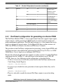
4.4.1 FlexTimer0 configuration for generating a 6-channel PWM.................................................................................23
4.4.2 FlexTimer1 configuration for position detection using a quadrature encoder.......................................................24
4.4.3 ADC and PDB module configurations...................................................................................................................25
4.4.4 ADC conversion timing, currents and voltage sampling.......................................................................................25
4.4.5 Current measurement.............................................................................................................................................26
4.4.6 Periodic interrupt timer configuration....................................................................................................................28
4.4.7 SPI configuration...................................................................................................................................................29
PMSM Vector Control with Quadrature Encoder on Kinetis, Rev. 0, 1/2012
Freescale Semiconductor, Inc.
3
Section Number
Title
Page
4.4.8 SCI (UART) configuration....................................................................................................................................29
4.5 Enabling the interrupts on the core level..........................................................................................................................30
4.6 FreeMASTER software....................................................................................................................................................32
4.6.1 Introduction............................................................................................................................................................32
4.6.2 FreeMASTER communication driver....................................................................................................................32
4.6.3 FreeMASTER recorder and scope.........................................................................................................................33
4.7 Program flow....................................................................................................................................................................33
4.7.1 Application structure..............................................................................................................................................33
4.7.2 Application background loop.................................................................................................................................34
4.7.3 Application state machine......................................................................................................................................35
4.7.3.1 States definition........................................................................................................................................36
4.7.3.2 Transitions definition...............................................................................................................................36
4.7.4 Interrupts................................................................................................................................................................37
4.7.4.1 PIT channel 0 interrupt............................................................................................................................37
4.7.4.2 ADC1 interrupt........................................................................................................................................38
4.7.4.3 PORTC interrupt......................................................................................................................................39
4.7.5 Project file structure...............................................................................................................................................40
4.7.6 Memory usage........................................................................................................................................................41
Chapter 5
Application Setup and Operation
5.1 Application set-up and operation .....................................................................................................................................43
Chapter 6
Measurement Results
6.1 CPU load and the execution time......................................................................................................................................45
6.2 Measurement results using FreeMASTER.......................................................................................................................45
6.2.1 3-phase current reconstruction...............................................................................................................................45
6.2.2 Speed controller.....................................................................................................................................................46
Chapter 7
References
7.1 References.........................................................................................................................................................................49
PMSM Vector Control with Quadrature Encoder on Kinetis, Rev. 0, 1/2012
4
Freescale Semiconductor, Inc.
Section Number
Title
Page
7.2 Acronyms and Abbreviations...........................................................................................................................................50
PMSM Vector Control with Quadrature Encoder on Kinetis, Rev. 0, 1/2012
Freescale Semiconductor, Inc.
5
PMSM Vector Control with Quadrature Encoder on Kinetis, Rev. 0, 1/2012
6
Freescale Semiconductor, Inc.
Chapter 1
Introduction
1.1 Introduction
This design reference manual describes the design of a 3-phase permanent magnet
synchronous motor (PMSM) vector control drive with quadrature encoder as a position
and a speed sensor. The application runs on the Kinetis K40 ARM Cortex-M4
microcontroller. The document briefly describes the theory of the PMSM vector control
and the hardware solution used. It is focused more on the application implementation on
the Kinetis K40 microcontroller. Although the paper describes implementation on the
Kinetis K40, the application can successfully run on any of the microcontrollers from the
Kinetis family.
Application features
• Vector control of a permanent magnet synchronous motor using the quadrature
encoder as a position sensor
• Targeted at the Tower rapid prototyping system (K40 tower board, Tower 3-phase
low voltage power stage)
• Vector control with a speed closed-loop
• Rotation in both directions
• Application speed ranges from 0% to 100% of nominal speed (no field weakening)
• Operation via user buttons on the Kinetis K40 tower board or via FreeMASTER
software
Solution Benefits
Kinetis is a mixed-signal MCU family based on the new ARM Cortex-M4 core and the
most scalable portfolio of mixed-signal ARM Cortex-M4 MCUs in the industry. Five
performance options are available from 50 to 150 MHz with flash memory ranging from
32 KB to 1 MB, and high RAM-to-flash ratios throughout. Common peripherals, memory
maps and packages both within and across the MCU families allow for easy migration to
PMSM Vector Control with Quadrature Encoder on Kinetis, Rev. 0, 1/2012
Freescale Semiconductor, Inc.
7
Introduction
greater or less memory and functionality. A vector control algorithm, demonstrated in
this application enables PM Synchronous Motor control with excellent dynamic
performance.
PMSM Vector Control with Quadrature Encoder on Kinetis, Rev. 0, 1/2012
8
Freescale Semiconductor, Inc.
Chapter 2
System Specification
2.1 System specification
The system solution is designed to drive a 3-phase PM synchronous motor. The
application meets the following performance specification:
• Application is targeted at the MK40x256 Kinetis ARM Cortex-M4 microcontroller
• Freescale’s Tower rapid prototyping system is used as the hardware platform
• The control technique incorporates:
• Vector control of a three-phase PM synchronous motor with quadrature encoder
• Closed-loop speed control
• Bi-directional rotation
• Close-loop current control
• Flux and torque independent control
• Starting up with alignment
• Field weakening is not implemented oReconstruction of three-phase motor
currents from two measured values
• 63 μs sampling period on the MK40 with the FreeMASTER recorder
• Works with the FreeMASTER software interface for application control and
monitoring:
• Required speed setting, start/stop status, motor current, system status, faults
acknowledgment
• Includes FreeMASTER software speed scope (observes actual and desired
speeds)
• Includes FreeMASTER software high-speed recorder (reconstructed motor
currents, voltages)
• Application includes overcurrent protection, different faults latched by the
MOSFET driver, and a motor phase disconnection.
• User buttons for manual control
PMSM Vector Control with Quadrature Encoder on Kinetis, Rev. 0, 1/2012
Freescale Semiconductor, Inc.
9
System specification
PMSM Vector Control with Quadrature Encoder on Kinetis, Rev. 0, 1/2012
10
Freescale Semiconductor, Inc.
Chapter 3
System Design
3.1 Control theory
3.1.1 3-phase permanent magnet synchronous motor
The construction of the PM synchronous motor and its mathematical description using a
space model can be found in the designer reference manual PM Sinusoidal Motor Vector
Control with Quadrature Encoder (document DRM105 [3]).
3.1.2 Introduction to vector control
The permanent magnet synchronous motor features (high efficiency, high torque
capability, high power density and durability) are good for using the PMSM in motioncontrol applications. The key idea for the vector control algorithm of the AC motors was
to achieve an AC motor torque/speed characteristic similar to that of the separately
excited DC motor. In the DC motor, the maximum torque is generated automatically by
the mechanical switch called the commutator. The commutator feeds current only to that
coil whose position is orthogonal to the direction of the magnetic flux generated by the
stator permanent magnets or excitation coils. The PMSM has the inverse construction, the
excitation is on the rotor and the motor has no commutator. It is possible to control these
two components independently and to reach the required performance, thanks to the
decomposition of the stator current into a magnetic field-generating part and a torquegenerating part. To keep the constant desired torque, the magnetic field generated by the
stator coils has to follow the rotor at the same synchronous speed. Therefore, to
successfully perform the vector control, the rotor shaft position must be known and is one
of the key variables in the vector control algorithm. For this purpose, either the
mechanical position sensors are used (encoders, resolvers and so on) or the position of
the shaft is calculated (estimated) from the motor phase currents and voltage. This is then
called sensorless control. Using the mechanical position, sensors bring several benefits.
The position is known over the entire speed range with the same precision, there is no
PMSM Vector Control with Quadrature Encoder on Kinetis, Rev. 0, 1/2012
Freescale Semiconductor, Inc.
11
Control theory
need to compute highly mathematically intensive algorithms that estimate the rotor shaft
position. So vector control with a position sensor can be implemented on less powerful
microcontrollers. The performance of the MCU can also be used for other tasks. On the
other hand, the cost of the mechanical sensor is a significant portion of the cost of the
whole drive.
Figure 3-1. Synchronous machine and the main principle of the vector control
As mentioned, the required torque is proportional to the q-portion of the orthogonal d,qcurrents system. The d-portion reflects the generation of the rotor magnetic flux. Because
there are permanent magnets mounted on the PMSM rotor, this current is usually kept at
a zero level, unless the field weakening is performed to accelerate the motor above the
nominal speed or while performing the MTPA algorithm. In such cases, the required dcurrent possesses a negative value.
Therefore, the control process (regulation) is focused on maintaining the desired values
of the d and q currents.
Because the d,q system is referenced to the rotor, the measured stator currents have to be
transformed from the 3-phase a,b,c stationary frame into the 2-phase d,q rotary frame
before they enter the regulator block. At first, the Clarke transformation is calculated,
which transforms the quantities from the 3-phase to 2-phase systems. Because the space
vector is defined in the plane (2D), it is sufficient to describe it in the 2-axis (alpha, beta)
coordinate system. Consequently, the result of the transformation into the 2-phase
PMSM Vector Control with Quadrature Encoder on Kinetis, Rev. 0, 1/2012
12
Freescale Semiconductor, Inc.
Chapter 3 System Design
synchronous frame (Park transformation) is two DC values – the d,q currents. It is much
easier to regulate two DC variables than two variables changing in time. The following
picture shows the transformation sequencing.
Figure 3-2. Transformation sequencing
3.1.3 Vector control implementation
There is an enhancement to the vector control algorithm implemented in the application
described in the designer reference manual PM Sinusoidal Motor Vector Control with
Quadrature Encoder (document DRM105 [3]). The limitations of the PI current
controllers are calculated in real time based on the available DC-bus voltage.
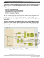
Figure 3-3 is a simplified block diagram of the vector control algorithm. The aim of this
control is to regulate the motor speed at a predefined level. The speed command value is
set by a high level control. The algorithm is executed in two control loops. The fast inner
control loop is executed within a hundred µsec period. The slow outer control loop is
executed within a period of an msec.
The fast control loop executes two independent current control loops. They are the direct
and quadrature-axis current (isd , isq) PI controllers. The direct-axis current is used to
control the rotor magnetizing flux. The quadrature-axis current corresponds to the motor
torque. The current PI controllers’ outputs are summed with the corresponding d and q
axis components of the decoupling stator voltage. Thus, the desired space vector for the
PMSM Vector Control with Quadrature Encoder on Kinetis, Rev. 0, 1/2012
Freescale Semiconductor, Inc.
13
Control theory
stator voltage is obtained and then applied to the motor. The fast control loop executes all
the necessary tasks to achieve an independent control of the stator current components.
These include:
• Three-phase current reconstruction
• Forward Clarke transformation
• Forward and backward Park transformations
• Rotor magnetizing flux position evaluation
• DC-bus voltage ripple elimination
• Space vector modulation (SVM)
The slow control loop executes the speed controller, field weakening control and lower
priority control tasks. The PI speed controller output sets a reference for the torque
producing quadrature axis component of the stator current iq_ref and the flux producing
current id_ref.
To achieve the goal of the PM synchronous motor control, the algorithm uses feedback
signals. The essential feedback signals are three-phase stator current and stator voltage.
For correct operation, the presented control structure requires a speed feedback on the
motor shaft. [5]
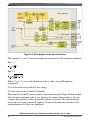
Figure 3-3. Simplified block diagram of PMSM vector control
PMSM Vector Control with Quadrature Encoder on Kinetis, Rev. 0, 1/2012
14
Freescale Semiconductor, Inc.
Chapter 3 System Design
In Figure 3-3, the algorithm of the PMSM vector control is represented as a chain of
functions. Outputs of one function serve as inputs to the other functions. Each body of the
functions contain mathematical equations not involving the peripherals. To speed-up the
development of any motor control applications, these motor control functions together
with some commonly used mathematic algorithms, such as trigonometric functions,
controllers, or limitations and digital filters, were placed into one set and create the Motor
Control Library. The motor control libraries are available for some Freescale MCU
platforms, optimized for each platform to maximize the use of available core features.
The functions were tested and are well documented. Therefore, building the motor
control application is much simpler for the developer.
3.1.3.1 PI current controllers limitations
As mentioned earlier, for a better motor dynamic performance the vector control
algorithm is enhanced to a dynamic limitation of the d- and q- current PI controller
outputs. The main reason is to require only the amount of voltage that is currently
available on the DC-bus. This approach, together with use of an anti-windup strategy in
the algorithm of the PI regulator, gives higher stability to the drive system during load
variations rather than using only the circle limitation of the output voltage vector. The
integrator inside the regulator algorithm stops when the power limitation occurs due to a
step increase of the load, or a DC-bus voltage drop.
The figure below is a block diagram of the fast (current) control loop, including the
computation of the current controller limitations.
PMSM Vector Control with Quadrature Encoder on Kinetis, Rev. 0, 1/2012
Freescale Semiconductor, Inc.
15
Control theory
Figure 3-4. Block diagram of the fast control loop
The equations 3-1 and 3-2 show the mathematical expression of the controllers limitation.
Eqn. 3-1
Eqn. 3-2
Where: Ud_Lim, Uq_Lim are the limitations of the d- and q- current PI regulators
respectively
UDCB is the actual value of the DC-bus voltage
Ud is the output of the d-current PI controller
The parameters of the PI current regulators were tuned using the Ziegler-Nichols method.
After the motor alignment in the d-axis, the rotor has stopped and according to the step
response the parameters of the d-current PI regulator were tuned. The same parameters
were used also for the q-current PI regulator, because of the difference in values of the
motor inductances Ld, Lq is not significant.
PMSM Vector Control with Quadrature Encoder on Kinetis, Rev. 0, 1/2012
16
Freescale Semiconductor, Inc.
Chapter 3 System Design
3.2 Hardware
The hardware solution of the PMSM Vector Control with Encoder on Kinetis is built on
the Freescale’s Tower rapid prototyping system. It consists of the following modules:
• Tower elevator modules (TWR-ELEV)
• Kinetis K40 tower module (TWR-K40X256)
• 3-phase low voltage power module (TWR-MC-LV3PH)
• Tower Serial Module (TWR-SER)
All modules of the Tower system are available to order via the Freescale web page or
from distributors. The user can easily build the hardware platform for which the
application is targeted.
3.2.1 Hardware set-up and configuration
Building the system using the modules of the Tower system is not difficult. The
peripheral modules and the MCU module are plugged into the elevator connectors, while
the white stripe on the side of the module boards determines the orientation to the
Functional elevator (the elevator with the mini USB connector, power supplies, and the
switch); see the following Figure 3-5.
PMSM Vector Control with Quadrature Encoder on Kinetis, Rev. 0, 1/2012
Freescale Semiconductor, Inc.
17
Hardware
Figure 3-5. Hardware built on the modules of the Tower system
It is recommended to place the MCU board on the top of the Tower system, this way the
user’s buttons are easily accessible.
It is necessary to configure the Tower 3-phase low-voltage power stage. The jumper
settings are listed in the following table and the jumper positions are highlighted in
Figure 3-6. See also the user’s manual [12] for more details (for example, hardware
overcurrent threshold setting) of the Tower low voltage power stage.
Table 3-1. Jumper settings of TWR-MC-LV3PH board
Jumper #
Setting
Note
J2
VDDA Source Select
1-2
Internal analog power supply
J3
VSSA Source Select
1-2
Internal analog power supply
J10
AN6 Signal Select
1-2
Phase C current signal
J11
AN5 Signal Select
1-2
Phase B current signal
J12
AN2 Signal Select
1-2
Phase A current signal
PMSM Vector Control with Quadrature Encoder on Kinetis, Rev. 0, 1/2012
18
Freescale Semiconductor, Inc.
Chapter 3 System Design
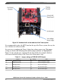
Figure 3-6. Jumpers and connectors positions on the TWR-MC-LV3PH
Table 3-2 shows the signal assignment of the motor and encoder connectors of the TWRMC-LV3PH. Because the FlexTimer module on the Kinetis K40 does not support the
index signal, this can be left disconnected.
Table 3-2. Motor and encoder connectors on the TWR-MC-LV3PH
Connector
Motor connector J5
Encoder connector J8
Pin#
Description
1
Motor phase A
2
Motor phase B
3
Motor phase C
1
5 V DC
2
GND
3
Encoder phase A
4
Encoder phase B
5
Encoder index
PMSM Vector Control with Quadrature Encoder on Kinetis, Rev. 0, 1/2012
Freescale Semiconductor, Inc.
19
Hardware
CAUTION
For Revision “B” of the TWR-MC-LV3PH — Do not plug any
other cables into the Tower system except for the power supply
cable and serial communication cable. Do not connect any USB
cable to the Tower system while the power is applied to the
power stage module TWR-MC-LV3PH. The demo system can
be powered only via the Tower Low Voltage Power Stage.
Connecting a USB cable to the Tower Elevator Module can
cause damage to the Kinetis K40. See Errata for the revision
“B” of the TWR-MC-LV3PH on how to correctly operate the
board.
The motor used in the reference design is a standard production industrial 3-phase PM
synchronous motor with an incremental encoder mounted on the shaft. The motor and the
sensor have the following specifications:
Table 3-3. Specification of the motor and incremental sensor
Motor Specification
Motor Model Parameters
Position Sensor Specification
Manufacturer name
TG Drives
Type
TGT2-0032-30-24/T0PS1KX-1M
Nominal Voltage (line-to-line)
18V
Nominal Speed
3000 rpm
Nominal Current (phase)
5.20 A
Nominal Torque
0.30 Nm
Stator Winding Resistance (line-to-line)
0.576 Ohm
Stator Winding Inductance d axis
0.468 mH
Stator Winding Inductance q axis
0.618 mH
Number of Pole-Pairs
3
Manufacturer name:
INDUcoder
Type:
ES 28-6-1024-05-D-R
Pulse Count per revolution
1024
Output
5 V±10 % TTL
PMSM Vector Control with Quadrature Encoder on Kinetis, Rev. 0, 1/2012
20
Freescale Semiconductor, Inc.
Chapter 4
Software Design
4.1 Software design
The application software was designed using the compiler IAR Embedded Workbench
for ARM v. 6.21
4.2 Fractional numbers representation
In the development of the vector control algorithm software libraries were used (a Set of
the General Maths and Motor Control Functions for the Cortex M4 Core). Most of the
mathematical calculations were performed with the numbers represented in Q1.15 or
Q1.31 signed fractional format, so all physical quantities were scaled to the <-1,1)
interval. For more on the fractional format and variables scaling, see DRM105 [3].
4.3 Application overview
The application is real-time interrupt-driven with the background infinite loop handling
the application states (Initialization, Run, Fault,…) and FreeMASTER communication
polling.
There are two periodic interrupt service routines where the control process is executed.
Their timing is given by the requirements of the vector control algorithm.
The control process is composed of two control loops. Execution of the fast (current)
control loop is performed in the ADC1 interrupt service routine, which is executed after
the values of the sampled DC bus voltage and motor phase currents are put into the ADC
result registers. The sampling instance is precisely defined by the hardware trigger of
FlexTimer0 that is configured to generate six PWM signals of frequency 16 kHz.
PMSM Vector Control with Quadrature Encoder on Kinetis, Rev. 0, 1/2012
Freescale Semiconductor, Inc.
21
Kinetis K40 peripheral modules configuration
The PIT0 interrupt service routine is triggered every one millisecond. In this ISR, the
speed is calculated as a position derivation and the speed controller (slow speed control
loop) is calculated.
The individual processes of the control routines are described in the following sections.
4.4 Kinetis K40 peripheral modules configuration
In this section, peripherals configuration procedures used are described or referenced. On
all Kinetis family devices, it is necessary to enable the system clock for the module
before any access to the peripheral registers is performed. The modules are enabled by
writing “1” to the particular bit in the System Clock Gate Control Register. Any write or
read attempt to the peripheral register before enabling the clock for a particular peripheral
module will yield a hard fault. Refer to [1] for a detailed description of each peripheral
module.
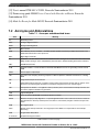
Table 4-1 shows an overview of the Kinetis K40 peripheral modules used by the
application, the number of modules and module channels reflect a 144-pin package.
Table 4-1. Kinetis K40 peripherals overview
Kinetis K40 peripherals
Group
Module
Number of modules or
channels
Analog
ADC
2 modules, both 23
channels single ended
and 3 differential pairs
Used in the application
Purpose
3 channels on
DC-bus voltage and
motor phase currents
sensing
ADC0
2 channels on
ADC1
Communications
Comparators
3
—
DAC
2
—
SPI
3
1
MOSFET driver
configuration
UART
6
1
FreeMASTER
communication
CAN
2
—
USB
1
—
I2C
2
—
SDHC
1
—
I2S
1
—
Table continues on the next page...
PMSM Vector Control with Quadrature Encoder on Kinetis, Rev. 0, 1/2012
22
Freescale Semiconductor, Inc.
Chapter 4 Software Design
Table 4-1. Kinetis K40 peripherals overview (continued)
Timers
FlexTimer
8 ch
6 ch
Generation 6-ch PWM
for motor control
2 ch
2 ch
Quadrature encoder
signals decoding
2 ch
—
PIT
4
1
1 ms time base for
speed calculation
PDB
2 ch for ADC triggering
2
DC-bus voltage and
phase current sampling
initiation
2 ch for DAC triggering
—
LPT
1
—
CMT
1
—
RTC
1
—
4.4.1 FlexTimer0 configuration for generating a 6-channel PWM
The FlexTimer Module (FTM) is a two to eight channel timer that supports input capture,
output compare, and the generation of PWM signals to control an electric motor and
power management applications. The FTM time reference is a 16-bit counter that can be
used as an unsigned or signed counter. On the Kinetis K40 there are three instances of
FTM. One FTM has 8 channels, the other two FTMs have 2 channels.
The procedure of the FlexTimer configuration for generating a center-aligned PWM with
dead time insertion is described in the application note titled Using FlexTimer in ACIM/
PMSM Motor Control Applications (document AN3729 [6]).
Because the referenced application note supports an earlier version (1.0) of the FlexTimer
implemented on the ColdFire V1, and with respect to the hardware used (TWR-MCLV3PH), there are a few differences in the configuration, as described below:
• At first, it is necessary to enable the system clock for the FlexTimer module in the
Clock Gating Control Register:
SIM_SCGC6 |= SIM_SCGC6_FTM0_MASK;
• It is necessary to disable the write protection of some registers before they can be
updated:
FTM0_MODE |= FTM_MODE_WPDIS_MASK;
• Then it is advisable to enable the internal FlexTimer counter to run in the debug
mode:
PMSM Vector Control with Quadrature Encoder on Kinetis, Rev. 0, 1/2012
Freescale Semiconductor, Inc.
23
Kinetis K40 peripheral modules configuration
FTM0_CONF |= FTM_CONF_BDMMODE(3);
While the HW debugging interface (jLink, Multilink,…) is connected to the
microcontroller, the MCU is in debug mode. This does not depend on the running
code containing breakpoints or not.
• The PWM signals generated by the FlexTimer0 are directly connected to the
MOSFET driver. Due to safety reasons, the input signals for the top transistors on the
MOSFET driver used on the Tower low voltage power stage have inversed polarity.
Therefore, it is also necessary to set the right polarity of the PWM signals:
FTM0_POL = FTM_POL_POL0_MASK |
FTM_POL_POL2_MASK |
FTM_POL_POL4_MASK;
• The duty cycle is changed by changing the value of the FlexTimer Value registers.
These registers are double-buffered, meaning that their values are updated not only
by writing the number, but it is necessary to confirm the change by setting the Load
Enable (LDOK) bit. This ensures that all values are updated at the same instance:
FTM0_PWMLOAD = FTM_PWMLOAD_LDOK_MASK;
It is necessary to write the LDOK bit every time the value registers are changed, so
not only at the stage of loading them with initial values, but with every update after
the duty cycle value is computed in the vector control algorithm.
• As mentioned in section 4.3.4, in this application, hardware triggering of the A/D
converter is employed. The Initialization Trigger signal from the FlexTimer is used
as the primary triggering signal, which is fed into the Programmable Delay Block
that services the timing of the AD conversion initiation.
FTM0_EXTTRIG |= FTM_EXTTRIG_INITTRIGEN_MASK;
• Finally, the output pins of the MCU have to be configured to bring the signals out of
the chip. The assignment of signals to output pins is set in the Pin Control Register,
while the available signals are listed in the Signal Multiplexing chapter of [1] and are
package dependent.
PORTC_PCR1
PORTC_PCR2
PORTC_PCR3
PORTC_PCR4
PORTD_PCR4
PORTD_PCR5
=
=
=
=
=
=
PORT_PCR_MUX(4);
PORT_PCR_MUX(4);
PORT_PCR_MUX(4);
PORT_PCR_MUX(4);
PORT_PCR_MUX(4);
PORT_PCR_MUX(4);
//
//
//
//
//
//
FTM0
FTM0
FTM0
FTM0
FTM0
FTM0
CH0
CH1
CH2
CH3
CH4
CH5
The port settings implemented in the application code of course reflect the hardware
solution built on the Tower system modules.
PMSM Vector Control with Quadrature Encoder on Kinetis, Rev. 0, 1/2012
24
Freescale Semiconductor, Inc.
Chapter 4 Software Design
4.4.2 FlexTimer1 configuration for position detection using a
quadrature encoder
FlexTimer1 is used in the application to decode the quadrature encoder signals. A
detailed procedure on configuring the FTM for this operation as well as the principle of
position and speed detection using a quadrature encoder is described in the application
note titled Configuring the FlexTimer for Position and Speed Measurement with an
Encoder (document number AN4381 [7]).
4.4.3 ADC and PDB module configurations
The on-chip ADC module is used to sample feedback signals (motor phase current and
DC bus voltage) that are necessary to successfully perform the vector control algorithm.
The Programmable Delay Block closely cooperates with the ADC and serves for
hardware triggering of the sampling.
It is required to perform a self-calibrating procedure of the ADC module before it is used
in the application to obtain a specified accuracy. The calibration process also requires a
programmer’s intervention to generate the plus-side and minus-side gain calibration
results and store them in the ADC plus-side gain and minus-side gain registers after the
calibration function completes. The calibration has to be performed for both ADC
modules. After calibration, the ADC modules are configured to a 12-bit accuracy. The
input clock of the ADC module is limited to 18 MHz according to the Kinetis K40
Datasheet [10]. The CPU frequency is set to 100 MHz, therefore by using an available
prescaler value the input clock to the ADC module is set to 12.5 MHz. That setting yields
a conversion time of 2.2 µs. Finally, the hardware trigger has to be enabled in the Status
and Control Register 2.
The Programmable Delay Block (PDB) provides controllable delays from either an
internal or an external trigger, or a programmable interval tick to the ADCs hardware
trigger inputs, so a precise timing between ADC conversions is achieved. The PDB
module has an internal counter that overflows on a modulo value. Because the input
trigger comes periodically from the FTM0, the input clock source and the modulo value
is set identically as for the FTM0 module. The values in the channel delay registers are
set to generate triggers to start sampling the DC-bus voltage and the motor phase AD
conversions. The PDB module on the K40 MCU allows 15 for different input trigger
sources. They are listed in the chapter “Chip configuration” in the section "PDB
Configuration” in [1]. Similarly in FTM0, the LDOK bit has to be set to acknowledge the
changes in the modulo and the delay registers.
PMSM Vector Control with Quadrature Encoder on Kinetis, Rev. 0, 1/2012
Freescale Semiconductor, Inc.
25
Kinetis K40 peripheral modules configuration
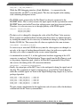
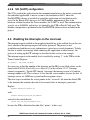
4.4.4 ADC conversion timing, currents and voltage sampling
The FlexTimer0 is configured to trigger an internal hardware signal when its counter is
reset after overflow to the initialization value. This signal is fed into the Programmable
Delay Block (PDB) that consequently triggers the AD conversion of the voltage and
currents with a predefined delay. On the Kinetis K40 MCU, two ADC modules are
implemented. Each ADC module associates to one channel of the PDB module. Each
ADC module has two result registers (two channels), and they correspond to two
programmable pre-trigger delays of the PDB channels. It is possible to perform four AD
conversions without requesting an interrupt (respecting that the DMA is not used for data
transfer). In this application, only three conversions need to be triggered without CPU
intervention (two motor phase currents and the DC-Bus voltage). The following time
diagram shows the modules interconnection and the ADC interrupt generation.
Figure 4-1. ADC conversion timing
PMSM Vector Control with Quadrature Encoder on Kinetis, Rev. 0, 1/2012
26
Freescale Semiconductor, Inc.
Chapter 4 Software Design
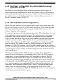
4.4.5 Current measurement
Closely related to the ADC conversion trigger timing is the assignment of the ADC
channels to the measured analog signals. For computation of the fast (current) control
loop of the FOC, it is necessary to know the values of all three motor phase currents.
Because there are only two ADC modules, it is possible to sample only two analog
quantities in one instance. Assuming the motor represents a symmetrical 3-phase system,
the sum of all three instantaneous phase currents is zero.
Eqn. 4-1
Because the phase currents are measured at the moment the bottom transistors are
conducting, in the case of high duty cycle ratios (current value is in the maximum area of
the sine curve), the time when the current can be measured is too short. The bottom
transistor must be switched on at least for a critical pulse width to get a stabilized current
shunt resistor voltage drop. The selection of the channels is done based on the section
where the space vector of the stator current is generated. This assignment is performed at
the end of the ADC1 interrupt service routine. Therefore, it is enough to sample only two
phase currents while the third is easily calculated according to eq. 4.2
Eqn. 4-2
Sector 1,6:
Sector 2,3:
Sector 4,5:
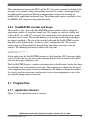
The following figure explains, in two cases (case I at 60°, case II at 30°) why the
calculation of the third current is necessary.
PMSM Vector Control with Quadrature Encoder on Kinetis, Rev. 0, 1/2012
Freescale Semiconductor, Inc.
27
Kinetis K40 peripheral modules configuration
Figure 4-2. Current sensing
At 60° all three currents can be sampled, the currents are sampled when the bottom
transistors are turned-on. The pulse width is sufficient to stabilize the current and to
perform the acquistion of the signal value by the AD converter. At 30°, the pulse is too
short, so the current of Phase A cannot be sampled.
PMSM Vector Control with Quadrature Encoder on Kinetis, Rev. 0, 1/2012
28
Freescale Semiconductor, Inc.
Chapter 4 Software Design
4.4.6 Periodic interrupt timer configuration
The PIT serves to generate a 1 ms time base for the slow (speed) control loop. There is
one PIT module with four channels implemented on the K40 MCU. The timer module
has an internal 32-bit counter clocked from the system clock. It possesses no prescalers.
The number of the value registers reflects the number of channels. The timer generates a
trigger at periodic intervals when enabled. It loads its start value as specified in the
LDVAL register, then counts down until it reaches 0. It then loads its respective start
value again. Each time the timer reaches 0, it will generate a trigger pulse and set the
interrupt flag. The initialization is short and is performed in four steps:
• Enabling the clock for the module in the particular System Clock Gating Control
Register,
• Enabling the internal module timer in the PIT Module Control Register,
• Writing the load value into the LDVAL Register
• Enabling the interrupt
Due to a bug on the chip mask 0M33Z (see Errata [14]), there has to be a certain software
workaround performed in the PIT interrupt service routine to allow generation of the next
interrupt:
1. Disable the interrupt first by clearing the TIE bit (while the TEN bit remained
unchanged):
PIT_TCTRL0 = 0x01;
2. Clear the interrupt flag:
PIT_TFLG0 = 0x01;
3. Enable the PIT interrupt again:
PIT_TCTRL0 = 0x03;
4.4.7 SPI configuration
The SPI interface is used in the application for communication between the intelligent
MOSFET driver MC33937 and the K40 MCU. The MC33937 driver is placed on the
Tower low voltage power module and serves for driving the high-side and low-side
MOSFET transistors of the 3-phase inverter. In the application, the initialization of the
MC33937 has to be performed, mainly in setting the dead time. During the motor run
there is also periodic checking of the status register of the driver (in the PIT interrupt), to
provide information on the latched faults. The MC33937 driver requires precise timing of
the SPI signals. The default MCU setting is not possible to use. The exact timing of the
SPI signals is listed in [8].
PMSM Vector Control with Quadrature Encoder on Kinetis, Rev. 0, 1/2012
Freescale Semiconductor, Inc.
29
Enabling the interrupts on the core level
4.4.8 SCI (UART) configuration
The SCI is used in the application for the communication between the master system and
the embedded application. A master system is the notebook or the PC where the
FreeMASTER software is installed to control the application and visualization of its
state. On the Kinetis K40, there are six UART modules implemented. Due to the
hardware solution based on the Tower modules, the UART3 is used. The communication
speed is set to 56000 Bd, and in fact, it is limited by the USB-to-Serial Cable used. The
module configuration is performed in the FreeMASTER software driver included in the
project.
4.5 Enabling the interrupts on the core level
The interrupt request enabled on the peripheral module has to be enabled also on the core
level, otherwise the interrupt request will not be generated. The process is not
straightforward and the necessary information is spread over several documents. To help
the user to enable any interrupt while enhancing the application to other features, the
process of setting-up the PIT interrupt is described in this section as an example.
The interrupt request on the module level is enabled by writing “1” to the TIE bit of the
Timer Control Register:
PIT_TCTRL0 |= PIT_TCTRL_TIE_MASK;
It is necessary to find the number of the interrupt and the IRQ vector. Both values can be
found in the K40 Sub-Family Reference Manual [1] in the section 3.2.2.3 “Interrupt
channel assignments”. For the PIT channel 1 interrupt, the interrupt vector is 84 and the
interrupt number is 68. This is always 16 less than the vector number, because the first 16
interrupt vectors are ARM core system handler exception vectors.
The next step is to redefine the vector pointer in the “vectors.h” file from the default ISR
to the function that contains the code to be executed after an interrupt is generated.
Replace
#define VECTOR_084 default_isr
with
#define VECTOR_084 PIT_CH0_ISR_Handler
and add at the end of the file:
extern void PIT_CH0_ISR_Handler(void);
because the ISR is defined in the other file (“main.c” in this case).
PMSM Vector Control with Quadrature Encoder on Kinetis, Rev. 0, 1/2012
30
Freescale Semiconductor, Inc.
Chapter 4 Software Design
Next, set-up the ARM core NVIC register. Each interrupt vector must be independently
enabled or disabled by setting the corresponding bit in the complementary pair of
registers, the Interrupt Set-Enable Register (NVIC_ISERx) or the Interrupt Clear-Enable
Register (NVIC_ICERx). NVIC_ISER0 contains the enable bits for IRQ numbers 0
through 31, NVIC_ISER1 contains the enable bits for IRQ 32 through 63, and so on. To
enable the PIT channel 0 interrupt (interrupt number 68), it is necessary to write
0x00000010 (b10000) to the NVIC_ISER2 register.
It is an advisable approach to clear any pending interrupt before it is enabled. This is
usually not necessary to do right after the reset when the MCU initialization is performed,
but during the program execution when a certain interrupt is disabled and later re-enabled
again. If an interrupt flag has been set before the interrupt was enabled, the interrupt
controller may generate an unhandled exception fault if the interrupt flag has not been
cleared before:
NVICICPR2 = 0x00000010; // clear pending interrupts first
NVICISER2 = 0x00000010; // enable the PIT CH0 interrupt
NOTE
The ARM document [9] indicates that the registers have an
underscore between NVIC and ISER (NVIC_ISER1).
However, in the current header files used in the application, the
NVIC register names do not have the underscore (NVICISER1
or NVICICPR1).
NVIC interrupts are prioritized by updating an 8-bit field within the 32-bit NVIC_IPRx
registers. Thanks to macros contained in the Kinetis K40 header file used in the project,
setting the priority of the interrupt has been simplified. The number of the interrupt is
used as one of the parameters of the NVIC_IP macro. The assigned value then determines
the priority (the higher the number, the higher the priority of the interrupt). If the
interrupt priority is not specified, the lower the number of the interrupt vector, the higher
priority the interrupt has by default. On the Kinetis family there are 16 levels of interrupt
priority implemented. However, the priority is set in the four MSBs of the 8-bit field:
NVIC_IP(68) = 0xF0; //set the highest priority for PIT ch. 0 interrupt.
The next step is to enable the interrupts globally by clearing a 1-bit special-purpose mask
register PRIMASK. The PRIMASK is cleared to 0 by the execution of the instruction
CPSIE i :
In the application this is defined as the macro:
#define EnableInterrupts asm(" CPSIE i ");
PMSM Vector Control with Quadrature Encoder on Kinetis, Rev. 0, 1/2012
Freescale Semiconductor, Inc.
31
FreeMASTER software
Finally, the interrupt service routine has to be defined “PIT_CH0_ISR_Handler” and inside the
body of the function, the source of the interrupt must be cleared to leave the interrupt
service routine. For the PIT channel 0 interrupt, this means that the interrupt flag is
cleared by writing “1” to the TIF bit of the Timer Flag Register:
PIT_TFLG0 = PIT_TFLG_TIF_MASK;
4.6 FreeMASTER software
4.6.1 Introduction
The FreeMASTER software was designed to provide a debugging, diagnostic, and
demonstrational tool for the development of algorithms and applications. Moreover, it is
useful for tuning the application for different power stages and motors, because almost all
of the application parameters can be changed via the FreeMASTER interface. This
consists of a component running on a PC and another part running on the target
controller. Nowadays, different communication interfaces are supported (RS-232, USB,
Ethernet, OSBDM,…) and the work on improvements and support for new families of
microcontrollers is still in progress.
In the application the RS232 interface is used, because it represents minimal
communication overhead that has to be handled by the MCU and requires no interrupts
(working in polling mode), which is important for motor control applications. A detailed
users guide of FreeMASTER, with useful hints for developing a motor control
application, can be found in the application note titled Real Time Development of MC
Applications using the PC Master Software Visualization Tool *document (AN1948
[11]).
4.6.2 FreeMASTER communication driver
On the MCU side, the FreeMASTER software driver is included in the project file
structure. It is a set of files supporting real-time data capture (Scope, Recorder) and
handling the communication protocol. There are some functions that are unique for each
MCU family, therefore FreeMASTER is issued for each MCU family separately. In the
“freemaster_cfg.h” file, the user can perform settings related to the communication and to
the data buffer. In the file are defined macros for conditional and parameter compilation.
The FreeMASTER driver does not perform any initialization or configuration of the SCI
module it uses to communicate.
PMSM Vector Control with Quadrature Encoder on Kinetis, Rev. 0, 1/2012
32
Freescale Semiconductor, Inc.
Chapter 4 Software Design
The communication between the MCU and the PC side can be performed with help of the
interrupt or via periodic calling of the polling function. For a motor control application,
the polling mode is preferred. Both the communication and protocol decoding are
handled in the application background loop. The polling mode requires a periodic call of
the FMSTR_Poll() function in the application main.
4.6.3 FreeMASTER recorder and scope
The recorder is also a part of the FreeMASTER software which is able to sample the
application variables at a specified sample rate. The samples are stored in a buffer and
read by the PC via an RS-232 serial port. The sampled data can be displayed in a graph,
or the data can be stored. The recorder behaves as an on-chip oscilloscope with trigger/
pre-trigger capabilities. The size of the recorder buffer and the FreeMASTER recorder
time base can be defined in the “freemaster_cfg.h” configuration file. The recorder
routine must be called periodically from the loop from where you want to take the
samples. The following line must be added to the loop code:
/* Freemaster recorder */
FMSTR_Recorder();
In this application, the FreeMASTER recorder is called from the ADC1 interrupt, which
creates a 63 μs time base for the recorder function. Buffered data is transferred to the PC
side after the trigger condition is met.
The FreeMASTER Scope is a similar visualization tool to the Recorder, but the data from
the embedded side is downloaded in real-time. The sampling rate is limited by the speed
of the communication protocol and also influenced by the number of displayed variables.
It is usually used for waveforms visualization of slow transient phenomena, such as the
speed profile during motor acceleration.
4.7 Program flow
4.7.1 Application structure
Figure 4-3 is the application software structure.
PMSM Vector Control with Quadrature Encoder on Kinetis, Rev. 0, 1/2012
Freescale Semiconductor, Inc.
33
Program flow
Figure 4-3. Application structure
The software structure consists of the application main routine which enters after the
CPU reset. Here the CPU and peripherals initialize, the Application State Machine is
serviced, and the interrupts generated periodically, where the motor control algorithms
are executed.
4.7.2 Application background loop
The endless application background loop contains only two lines - calls to two functions:
The FreeMASTER communication polling function FMSTR_Poll();
The application state machine AppStateMachine[appState]();
The main application-control tasks are executed in the interrupt service routines that
interrupt the background loop.
PMSM Vector Control with Quadrature Encoder on Kinetis, Rev. 0, 1/2012
34
Freescale Semiconductor, Inc.
Chapter 4 Software Design
4.7.3 Application state machine
A simple application state machine handles the switching between the application states
and application state transitions. This is executed in the infinite background loop in the
program main. The following figure gives an overview of the program flow through the
application states and transitions.
Figure 4-4. Application state machine diagram
The application states represent a steady state. This means that usually, the application is
waiting on some trigger or condition to change the state. The particular function is called
each time the program makes one pass of the infinite background loop. The application
state transitions contain instructions that are executed only once when the application
state is changed. Typically, the settings in the peripheral registers are performed only
once, and it is not necessary to repeat them.
PMSM Vector Control with Quadrature Encoder on Kinetis, Rev. 0, 1/2012
Freescale Semiconductor, Inc.
35
Program flow
4.7.3.1 States definition
• APP_INIT
The default state after the MCU reset. The peripherals are configured, the
MOSFET driver MC33937 is initialized and the interrupts are enabled. This
particular state function is executed only once and transitions to the Calibration
state.
• APP_CALIBRATION
Calibration of the offset on the ADC channels for all three phase currents is
performed. The values are stored in the ADC offset registers. The offset value
represents the zero current and is automatically subtracted from the sampled
value during the motor run, so there is already a positive or negative value of the
current available in the ADC result register.
• APP_ALIGNMENT
The rotor is aligned to a known position by applying only the d-portion of d,q
current system.
• APP_STOP
The application is fully initialized and is awaiting the start of the motor run,
either by pressing the Start button or setting the state variable from the
FreeMASTER software. The PWM output pads are still disabled. The Stop state
can also be entered from the Run state.
• APP_RUN
The voltage is applied to the motor and the speed of the motor is regulated
according to the required speed profile.
• APP_FAULT
The application waits for the fault removal and fault acknowledgment.
4.7.3.2 Transitions definition
• AppInitToCalib
In this subroutine, all application variables are initialized to their default values.
• AppCalibToAlign
Enables the PWM output pads, assigns the default ADC channels to the ADC
modules and enables the ADC interrupt, so that the vector control algorithm can
be performed during the rotor alignment process.
• AppAlignToStop
PMSM Vector Control with Quadrature Encoder on Kinetis, Rev. 0, 1/2012
36
Freescale Semiconductor, Inc.
Chapter 4 Software Design
•
•
•
•
•
After the rotor alignment, the quadrature decoder counter (FTM1 counter) is
cleared and all variables are set to their default values. The PWM output pads are
disabled.
AppStopToRun
The PWM output pads are enabled and the variables are again set to default
values (except for the speed and position related calculation), just in case there
was an attempt to run the motor in the stop state. Toggling the user’s LEDs on
the K40 tower board signals the change of state.
AppRunToStop
If the speed is non-zero, the application waits till the motor stops by forcing the
required speed to zero. If the motor is in standstill, the PWM output pads are
disabled. Toggling the user’s LEDs on the K40 tower board signals the change
of state.
AppRunToFault
The PWM output pads are disabled. The user’s LEDs on the K40 tower board
are toggled to signal the change of the state. See the triggering events in Section
5.
AppStopToFault
In the Stop state measurement of the DC-Bus voltage is performed, and the value
is compared against the overvoltage threshold. The application can enter the
Fault state from the Stop state in the case of an overvoltage error.
AppFaultToStop
Performing the reset and re-initialization of the MC33937 MOSFET driver after
a fault was acknowledged.
4.7.4 Interrupts
The application requires the minimum number of interrupts because the MCU has the
possibility of hardware triggering the AD conversion and the FlexTimer is able to
effectively decode quadrature encoder signals.
4.7.4.1 PIT channel 0 interrupt
In this interrupt service routine, the speed control loop is executed and the interrupt also
serves as a precise 1 ms time base for speed computing. Because the speed is calculated
as a derivation of the position, the precision of the time base is critical for obtaining the
speed values. Therefore, the interrupt has the highest priority. The speed calculation is
described in the application note titled Configuring the FlexTimer for Position and Speed
Measurement with an Encoder (document AN4381 [7]).
PMSM Vector Control with Quadrature Encoder on Kinetis, Rev. 0, 1/2012
Freescale Semiconductor, Inc.
37
Program flow
After the speed calculation, there is detection of the disconnected motor phase. The loss
of the voltage on one motor phase results in the generation of a rotating magnetic field in
the opposite direction than that of the required speed. The PI speed regulator generates
each time a higher value of iq (torque producing) current because the regulation error
between the measured and required speed increases during acceleration. The motor
reaches quickly the maximum speed in the opposite direction. This behavior is unwanted
and needs to be managed by software. The detection is based on the hazardous state
described above. The required and actual speed has to have the same orientation,
otherwise the fault is triggered and the motor is disconnected from the voltage.
Then, the speed PI controller is calculated. The step change in the required speed is ramp
limited prior to the regulation error being computed. As mentioned, the output of the
speed regulator is the required q-axis component of the current that is directly
proportional to the required torque needed for motor acceleration, or for overcoming all
drive frictions while maintaining a constant speed.
In the PIT channel 0 ISR, there is also a periodic check on the status register of the
MOSFET driver MC33937 via the SPI interface. When any fault is latched by the driver,
the application is forced into the fault state and the user can check the source of the fault
via the FreeMASTER control interface. For more details, see the User’s Manual [13].
Table 4-2 summarizes the software routines executed in the PIT CH0 ISR.
Table 4-2. Software routines executed in the PIT CH0 ISR
Speed calculation
PIT CH0 ISR
Speed filtering (moving average)
Motor phase disconnection detection
Ramp limitation of the required speed
Speed PI controller calculation
MOSFET driver status register check
4.7.4.2 ADC1 interrupt
This interrupt request is triggered when the conversion of channel A of the ADC1 module
is completed. At the moment of the interrupt generation, there are sampled values of
physical quantities ready: in the Result Registers A of the ADC0 (DC bus voltage),
Result Register B of the ADC0 (motor phase current 1) and Result Register A of the
ADC1 module (motor phase current 2). The interrupt is always enabled only for one
module, otherwise there would be two interrupt requests generated at the same time; this
is because the triggers for motor phase currents are generated in the same instance. In the
PMSM Vector Control with Quadrature Encoder on Kinetis, Rev. 0, 1/2012
38
Freescale Semiconductor, Inc.
Chapter 4 Software Design
ADC1 ISR there is the fast (current) control loop of the PMSM vector control executed.
Besides the control algorithm computation, there are also other supporting routines
executed, an overview is summarized in the following table.
Table 4-3. Software routines executed in the ADC1 ISR
Reading the ADC result registers (2) based on the actual SVM sector, calculation
of the third current
ADC1 ISR
Software overcurrent and overvoltage detection
Calculation of the rotor position from the encoder signals
Clarke transformation
Fast control loop
Sin
Cos
Park transformation
D-current controller output limitation
calculation
D-current PI controller
Q-current controller output limitation
calculation (included SQRT)
Q-current PI controller
Inverse Park transformation
Elimination of DC bus voltage ripple
Space vector modulation
PWM registers update (with the calculated duty cycle)
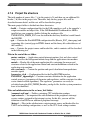
4.7.4.3 PORTC interrupt
Handling user buttons on the K40 tower board is performed in the ISR associated with
the PORTC interrupt, generated whenever one of the buttons is pressed. At the beginning
of the ISR, simple logic is executed to evaluate what button is pressed, and the interrupt
flag is cleared. Because there are only two user buttons (in the application the assigned
functions are RUN and STOP), there is limited control possibility (rotation only in one
direction). Pressing the RUN button causes the speed to increase in 10% steps. Pressing
the STOP button causes the speed to decrease in 10% steps and also a fault
acknowledgment.
More about the application control via the user buttons in the chapter “Application
control”. Using the FreeMASTER control interface allows for enhanced control and
diagnostic. See details in the same chapter.
PMSM Vector Control with Quadrature Encoder on Kinetis, Rev. 0, 1/2012
Freescale Semiconductor, Inc.
39
Program flow
4.7.5 Project file structure
The total number of source files (*.c) in the project is 36 and there are an additional 86
header (*.h) files in the project tree. Therefore, only the key project files will be
described in more detail, and the rest will be described in groups.
The main project folder is divided into three directories:
• build — Contains configuration files for the IAR compiler as well as the compiler’s
output executable and object files. If the IAR Embedded Workbench for ARM is
installed on your computer, double clicking the workspace file
TWRK40X256_PMSM_FOC.eww located in the directory \build\iar\ would launch
the IAR IDE.
• gui — Contains the FreeMASTER configuration file (Kinetis_FOC_demo.pmp) and
supporting files (control page in HTML format and the binary file with addresses of
the variables)
• src — Contains the project source and header files, and its contents will be described
in the following text.
Files in the root of the src folder:
main.c contains — Application control interrupt routines (fast and slow control
loops) as well as the background infinite loop with the application state machine
main.h — Header file of the main application file, containing the macros and
structures related to the application control and constant definitions related to the
application state machine.
enc.c and enc.h — Contain the position and speed calculation from quadrature
encoder signals
freemaster_cfg.h — Configuration file for the FreeMASTER interface
PMSMFOC_appconfig.h — Contains constants definition for the application
control processes (parameters of the motor and regulators, and the constants for other
vector control related algorithms). The regulators’ parameters can easily be
calculated using the K40_PMSM_Encoder_config.xls file, but the system parameters
have to be identified.
Files and subdirectories in the src\mcu_Init\ folder:
\common\ and \cpu\ — Folders containing CPU initialization routines
\cpu\vectors.h — An important file with definition of the peripherals interrupt
service routines assigned to the interrupt vectors. In this file, you can add the
definition of an ISR for an additional peripheral interrupt.
\drivers\ — Files in the subdirectories contain generic source and header files for
UART and watchdog configuration, as well as the CPU clock settings routines
PMSM Vector Control with Quadrature Encoder on Kinetis, Rev. 0, 1/2012
40
Freescale Semiconductor, Inc.
Chapter 4 Software Design
\peripherals\ — Contains important files for static configuration of the peripherals
used in the application (FlexTimers, ADC, PDB, SPI, PIT)
\platforms\tower.h — Contains the Kinetis Tower card definitions (CPU speed and
UART parameters)
Files in the src\twrk40x256\ folder:
MK40X256VMD100.h — Header file containing macro definitions of all the MCU
registers and register bits
Files in the src\MC_Lib\ folder:
Cortex_M4.a — Software library containing motor control, general math and filter
algorithms.Other files in the folder and subfolders are associated header files, each
one for a particular function of the library.
Other subdirectories in the src\ folder:s
\src\FreeMASTER — Contains all source files of the FreeMASTER application, it
is not necessary to access it or change anything inside. The interface to the
programmer is only via freemaster_cfg.h file.
\src\Common — Contains specific header files associated with the software libraries
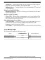
4.7.6 Memory usage
The following table summarizes chip memory usage:
Memory
Program Flash (application code)
Total Available on the Kinetis
MK40X256VMD100
256 000
Data Flash (application constants)
Data RAM (application variables)
Used by the Application
20 994
2 106
64 000
1 662
PMSM Vector Control with Quadrature Encoder on Kinetis, Rev. 0, 1/2012
Freescale Semiconductor, Inc.
41
Program flow
PMSM Vector Control with Quadrature Encoder on Kinetis, Rev. 0, 1/2012
42
Freescale Semiconductor, Inc.
Chapter 5
Application Setup and Operation
5.1 Application set-up and operation
The application can be operated via the user’s buttons on the K40 tower module or via
the FreeMASTER interface. The set-up procedure of the FreeMASTER software on the
PC, as well as the application operation, is described in the User’s Manual [13].
PMSM Vector Control with Quadrature Encoder on Kinetis, Rev. 0, 1/2012
Freescale Semiconductor, Inc.
43
Application set-up and operation
PMSM Vector Control with Quadrature Encoder on Kinetis, Rev. 0, 1/2012
44
Freescale Semiconductor, Inc.
Chapter 6
Measurement Results
6.1 CPU load and the execution time
The CPU load is influenced mainly by the execution of the ADC1 ISR, in which the
calculation of the fast (current) control loop of the PMSM vector control is performed.
The complete ADC1 ISR requires 1628 machine cycles. It is executed periodically with
the same frequency as the PWM reload event, when the values of the duty cycles are
updated.
In this application, the fast control loop is executed once per 63 µs which corresponds to
16 kHz of the PWM frequency. At 100 MHz on the Kinetis K40 device, it consumes
roughly 35% of CPU performance.
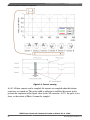
6.2 Measurement results using FreeMASTER
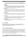
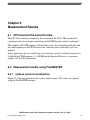
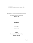
6.2.1 3-phase current reconstruction
Figure 6.2, is the measurement of the 3-phase motor currents. The values are captured
using the FreeMASTER recorder.
PMSM Vector Control with Quadrature Encoder on Kinetis, Rev. 0, 1/2012
Freescale Semiconductor, Inc.
45
Measurement results using FreeMASTER
Figure 6-1. Motor phase currents and SVM sector
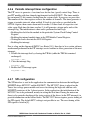
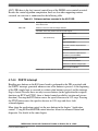
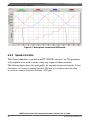
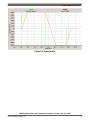
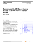
6.2.2 Speed controller
The PI speed controller is executed in the PIT CH0 ISR, once per 1 ms. The parameters
of the regulator were tuned to obtain a sharp step response without overshoot.
The following figure shows the speed profile; the required and measured speeds. At first,
the motor is set to run at a nominal speed of 3000 rpm in a clockwise direction, then
reversed to a counter-clockwise direction, -3000 rpm.
PMSM Vector Control with Quadrature Encoder on Kinetis, Rev. 0, 1/2012
46
Freescale Semiconductor, Inc.
Chapter 6 Measurement Results
Figure 6-2. Speed profile
PMSM Vector Control with Quadrature Encoder on Kinetis, Rev. 0, 1/2012
Freescale Semiconductor, Inc.
47
Measurement results using FreeMASTER
PMSM Vector Control with Quadrature Encoder on Kinetis, Rev. 0, 1/2012
48
Freescale Semiconductor, Inc.
Chapter 7
References
7.1 References
[1] K40 Sub-Family Reference Manual, Freescale Semiconductor, 2011
[2] IAR C/C++ Development Guide, Compiling and Linking for Advanced RISC
Machines Ltd’s ARM® Cores, IAR Systems AB, 2011
[3] Designer reference manual titled PM Sinusoidal Motor Vector Control with
Quadrature Encoder (document DRM105) Devices Supported—MCF51AC256,
Freescale Semiconductor, 2008
[4] User reference manual Set of General Math and Motor Control Functions for Cortex
M4 Core (document number MCLIBCORETXM4UG) Freescale Semiconductor, 2011
[5] Matus Plachy, Anders Lundgren, Lotta Frimanson: Designing advanced DSP
applications on the Kinetis Cortex-M4 MCU Embedded World 2011 Conference and
Exhibition
[6] Application note titled Using FlexTimer in ACIM/PMSM Motor Control Applications
(document number AN3729) Freescale Semiconductor, 2008
[7] Application note titled Configuring FlexTimer for Position and Speed Measurement
with Encoder (document number AN4381) Freescale Semiconductor 2011
[8] Advanced information documet titled Three Phase Field Effect Transistor Pre-driver
(document number MC33937) Freescale Semiconductor 2009
[9] Reference Manual titled ARM®v7-M Architecture , ARM Limited 2010
[10] Data sheet titled K40 Sub-Family Data Sheet (document number
K40P144M100SF2), Freescale Semiconductor 2011
[11] Application note titled Real Time Development of MC Applications using the PC
Master Software Visualization Tool (document numberAN1948) , Freescale
Semiconductor 2005
PMSM Vector Control with Quadrature Encoder on Kinetis, Rev. 0, 1/2012
Freescale Semiconductor, Inc.
49
Acronyms and Abbreviations
[12] User’s manual TWR–MC–LV3PH , Freescale Semiconductor 2011
[13] Demo set-up guide PMSM Vector Control with Encoder on Kinetis, Freescale
Semiconductor 2011
[14] Mask Set Errata for Mask 0M33Z, Freescale Semiconductor 2011
7.2 Acronyms and Abbreviations
Table 7-1. Acronyms and abbreviated terms
Term
Meaning
AC
Alternating current
ADC
Analog-to-digital converter
BDM
Background Debug Mode
DC
Direct current
DMA
Direct Memory Access Controller — An MCU module capable of performing complex data transfers with
minimal intervention from a host processor.
DSC
Digital Signal Controller
DT
Dead time — A short time that must be inserted between the turning off of one transistor in the inverter half
bridge and the turning on of the complementary transistor due to limited switching speed of the transistors
FOC
Field Oriented Control
FTM
FlexTimer module — A timer module on the Kinetis K40 MCU that serves for generating of the 6-channel
PWM
GPIO
General purpose input/output
IAR
The name of the company producing compilers for different platforms and MCU manufacturers, including
ARM
IDE
Integrated Development Environment
I/O
Input/output interfaces between a computer system and the external world. A CPU reads an input to sense
the level of an external signal and writes to an output to change the level of an external signal.
ISR
Interrupt Service Routine — A fragment of code (a function) that is executed when interrupts from the core
or from the peripheral modules are generated.
LED
Light emitting diode
K40
Freescale Kinetis MK40 ARM Cortex-M4 32-bit microcontroller
MTPA
Maximum Torque per Amp Algorithm — A special algorithm used in vector control of AC motors. Thanks to
this algorithm, the efficiency and the power of the motor is increased by using the reluctance torque of the
motor.
MSB
Most Significant Bit
NVIC
Nested Vector Interrupt Controller— An integral part of the ARMv7 core responsible for the interrupts
processing
PDB
Programmable Delay Block
PI controller
Proportional-integral controller
Table continues on the next page...
PMSM Vector Control with Quadrature Encoder on Kinetis, Rev. 0, 1/2012
50
Freescale Semiconductor, Inc.
Chapter 7 References
Table 7-1. Acronyms and abbreviated terms (continued)
Term
Meaning
PIT
Periodic Interrupt Timer
PMSM
PM Synchronous Motor, permanent magnet synchronous motor
PWM
Pulse Width Modulation
RPM
Revolutions Per Minute
SCI
Serial Communication Interface, see also UART
SPI
Serial Peripheral Interface
UART
Universal Asynchronous Receiver/Transmitter — An MCU peripheral module allowing asynchronous serial
communication between the MCU and other systems
PMSM Vector Control with Quadrature Encoder on Kinetis, Rev. 0, 1/2012
Freescale Semiconductor, Inc.
51
Acronyms and Abbreviations
PMSM Vector Control with Quadrature Encoder on Kinetis, Rev. 0, 1/2012
52
Freescale Semiconductor, Inc.
How to Reach Us:
Home Page:
www.freescale.com
Web Support:
http://www.freescale.com/support
USA/Europe or Locations Not Listed:
Freescale Semiconductor
Technical Information Center, EL516
2100 East Elliot Road
Tempe, Arizona 85284
+1-800-521-6274 or +1-480-768-2130
www.freescale.com/support
Europe, Middle East, and Africa:
Freescale Halbleiter Deutschland GmbH
Technical Information Center
Schatzbogen 7
81829 Muenchen, Germany
+44 1296 380 456 (English)
+46 8 52200080 (English)
+49 89 92103 559 (German)
+33 1 69 35 48 48 (French)
www.freescale.com/support
Japan:
Freescale Semiconductor Japan Ltd.
Headquarters
ARCO Tower 15F
1-8-1, Shimo-Meguro, Meguro-ku,
Tokyo 153-0064
Japan
0120 191014 or +81 3 5437 9125
[email protected]
Asia/Pacific:
Freescale Semiconductor China Ltd.
Exchange Building 23F
No. 118 Jianguo Road
Chaoyang District
Beijing 100022
China
+86 10 5879 8000
[email protected]
For Literature Requests Only:
Freescale Semiconductor Literature Distribution Center
1-800-441-2447 or +1-303-675-2140
Fax: +1-303-675-2150
[email protected]
Document Number: DRM128
Rev. 0, 1/2012
Information in this document is provided solely to enable system and software
implementers to use Freescale Semiconductors products. There are no express or implied
copyright licenses granted hereunder to design or fabricate any integrated circuits or
integrated circuits based on the information in this document.
Freescale Semiconductor reserves the right to make changes without further notice to any
products herein. Freescale Semiconductor makes no warranty, representation, or
guarantee regarding the suitability of its products for any particular purpose, nor does
Freescale Semiconductor assume any liability arising out of the application or use of any
product or circuit, and specifically disclaims any liability, including without limitation
consequential or incidental damages. "Typical" parameters that may be provided in
Freescale Semiconductor data sheets and/or specifications can and do vary in different
applications and actual performance may vary over time. All operating parameters,
including "Typicals", must be validated for each customer application by customer's
technical experts. Freescale Semiconductor does not convey any license under its patent
rights nor the rights of others. Freescale Semiconductor products are not designed,
intended, or authorized for use as components in systems intended for surgical implant
into the body, or other applications intended to support or sustain life, or for any other
application in which failure of the Freescale Semiconductor product could create a
situation where personal injury or death may occur. Should Buyer purchase or use
Freescale Semiconductor products for any such unintended or unauthorized application,
Buyer shall indemnify Freescale Semiconductor and its officers, employees, subsidiaries,
affiliates, and distributors harmless against all claims, costs, damages, and expenses, and
reasonable attorney fees arising out of, directly or indirectly, any claim of personal injury
or death associated with such unintended or unauthorized use, even if such claims alleges
that Freescale Semiconductor was negligent regarding the design or manufacture of
the part.
RoHS-compliant and/or Pb-free versions of Freescale products have the functionality and
electrical characteristics as their non-RoHS-complaint and/or non-Pb-free counterparts.
For further information, see http://www.freescale.com or contact your Freescale
sales representative.
For information on Freescale's Environmental Products program, go to
http://www.freescale.com/epp.
Freescale™ and the Freescale logo are trademarks of Freescale Semiconductor, Inc.
All other product or service names are the property of their respective owners.
© 2012 Freescale Semiconductor, Inc.