1
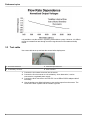
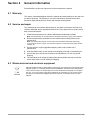
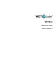
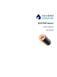
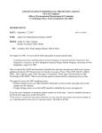
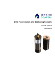
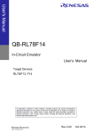
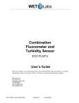
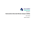
WETStar
User manual
12/2013, Edition 1
Table of Contents
Section 1 Specifications ....................................................................................................................3
1.1 Mechanical...................................................................................................................................3
1.1.1 Bulkhead connector.............................................................................................................3
1.2 Electrical.......................................................................................................................................3
1.3 Communications..........................................................................................................................3
1.4 Optical..........................................................................................................................................3
Section 2 Operation ............................................................................................................................5
2.1 Analog functional check...............................................................................................................5
2.1.1 Digital output check.............................................................................................................5
2.2 Deployment..................................................................................................................................5
2.2.1 Data collection.....................................................................................................................6
2.3 Clean the sensor..........................................................................................................................6
2.3.1 Bulkhead connector maintenance.......................................................................................6
Section 3 Reference topics ...............................................................................................................7
3.1 Delivered items............................................................................................................................7
3.2 Characterization...........................................................................................................................7
3.2.1 Field characterization..........................................................................................................7
3.2.1.1 Flow rate dependence................................................................................................7
3.3 Test cable....................................................................................................................................8
Section 4 General information .........................................................................................................9
4.1 Warranty.......................................................................................................................................9
4.2 Service and repair........................................................................................................................9
4.3 Waste electrical and electronic equipment...................................................................................9
1
Table of Contents
2
Section 1
Specifications
1.1 Mechanical
Diameter
6.98 cm
Length
17.1 cm; 25.7 cm with tubing
Depth rating
600 m
Temperature range
0–30 °C
Weight in air, water
0.8 kg, 0.1 kg
1.1.1 Bulkhead connector
Pin
Function
1
Ground
2
Reserved
3
Reserved
4
Voltage in
5
TX
6
Analog out
MCBH-6-MP connector
1.2 Electrical
Input
7–15 VDC
Current draw
< 40 mA (standard); < 80 mA (digital)
Linearity
99%
1.3 Communications
Maximum output, digital
~4095 counts
Maximum output, analog
5V
Response time, digital
0.125 seconds
Response time, analog
0.17 seconds
1.4 Optical
Parameter
Wavelength EX/EM
Range, Sensitivity
Chlorophyll (Chl)
460/695 nm
0.03–75, 0.03 µg/L (standard)
0.06–150, 0.03 µg/L
Colored Dissolved Organic
Matter (CDOM)
370/460 nm
0–250, 0.1 ppb (near-coastal)
0–100, 0.1 ppb open ocean
Uranine (UR)
485/532 nm
0–4000, 1 µg/L
3
Specifications
4
Section 2
Operation
This sensor measures the quantity of fluorescence emitted from a given sample of water.
The sample flows through the sensor and is excited by the sensor's light source. This
causes the sample to emit absorbed energy as fluorescence.
CAUTION
CDOM sensors use UV LED light. Do not look directly at a UV LED when it is on. It can damage
the eyes. Keep products that have UV LEDs away from children, pets, and other living organisms.
Wear polycarbonate UV-resistant safety glasses to protect the eyes when a UV LED is on.
NOTICE
Do not supply more than 15 VDC to the sensor. More than 15 VDC will damage the sensor.
2.1 Analog functional check
1. Supply 12 VDC to the sensor.
The sensor comes on.
2. Use the probes on a digital multimeter (DMM) to touch the RCA connector on the
auxiliary leg(s) of the test cable. Refer to the section on the Test cable on page 8
for details about test cables.
3. Put the red (signal) probe in the RCA connector and the black (ground) on the
outside.
The DMM shows near 0 VDC.
4. Put the fluorescent stick (for fluorometers) or a solid object near the light source of
the sensor.
The DMM shows near 5 VDC.
2.1.1 Digital output check
1. Connect the test cable to the sensor.
Refer to the section about the Test cable on page 8 for information on the test
cable.
2. Connect the DB-9 connector on the test cable to a PC.
3. Connect the test cable to a regulated power supply or a 9 V battery.
4. Start a terminal communication program such as HyperTerminal® or Terra Term.
Select:
a. Bits per second: 9600
b. Data bits: 8
c. Parity: none
d. Stop bits: 1
e. Flow control: none.
5. Turn the power supply on if necessary.
The digital output is a column of zeros.
6. Put the fluorescent stick in the flow tube of the sensor.
The output increases to the maximum output (in counts) specified for the sensor.
2.2 Deployment
Deploy the sensor with or without a pump. The manufacturer recommends using a pump
because it supplies a consistent flow of water through the sensor. The manufacturer
supplies threaded tubing nipples for the flow tube ports to use with a pump or water trap.
Note: Use an RS232 cable less than 5 m long unless a longer cable has been tested.
5
Operation
The manufacturer recommends a flow rate of 25 ml/sec using a pump made by Sea-Bird
Electronics. The SBE-05T has an adjustable motor speed so the user can control the flow
rate into the sensor. Refer to the section on flow rate dependence for more information.
If the user deploys the sensor in a free-flow mode without a pump, make sure that the
sensor has a clear water path during descent. Use a water trap if necessary: this is a
funnel-type device attached to the sensor with the wide end pointed toward the direction
of deployment. The manufacturer recommends a descent rate of 0.2–1.0 m/sec.
2.2.1 Data collection
Connect digital sensors to a PC or data logger that can receive an RS232 signal at
19200 baud. Connection to a PC or data logger also lets the user save the sensor's data.
Connect analog sensors to a host such as a data logger, radiometer, or CTD
(conductivity-temperature-depth) that can digitize the analog output of the sensor. A data
logger will merge CTD and sensor data and correlate the sensor output with depth or
time.
2.3 Clean the sensor
CAUTION
Clean the quartz flow tube carefully. It scratches and breaks easily.
1. After each cast or exposure to natural water, flush the sensor with clean fresh water.
2. Clean any grease or oil with soapy water.
a. Solvents such as methanol can be used to clean the flow tube. Use a long cotton
swab to reach the length of the flow tube.
b. Rinse the sensor thoroughly inside and outside.
3. Let the sensor dry in air.
2.3.1 Bulkhead connector maintenance
Lubricate the mating surfaces of bulkhead connectors at regular intervals with pure
silicone spray only. Allow the contacts to dry before they are connected.
Make sure that the pins have no corrosion, which looks green and dull. Make sure that
the rubber seals on the pins are not delaminated. Connectors should mate smoothly and
not feel "gritty" or too resistant.
The manufacturer recommends 3M™ Silicone Lubricant spray (UPC 021200-85822).
Other silicone sprays may contain hydrocarbon solvents that damage rubber.
DO NOT use silicone grease. DO NOT use WD-40®. The wrong lubricant will cause the
bulkhead connector to fail prematurely and the sensor will flood.
6
Section 3
Reference topics
3.1 Delivered items
•
•
•
•
•
•
•
The sensor
dummy plug with lock collar
1 nozzle, 6.9 cm
1 nozzle, 3.8 cm
fluorescent stick
user manual
characterization page
3.2 Characterization
The manufacturer characterizes all fluorescence sensors using a fluorescing material to
make sure that the data that is collected meets the sensor's specifications. This
information is on the sensor-specific characterization page that ships with the sensor.
3.2.1 Field characterization
The manufacturer recommends that the user perform a field characterization on
fluorometers to make sure that the data output is as accurate as possible for the user's
application. The scale factor and dark counts values can vary depending on the natural
water, temperature, cable length, power supply, and other factors.
Do the steps below to field-characterize the sensor.
•
•
•
•
x = the solution of a known concentration in volts or counts.
output = the measured sample of interest in volts or counts.
clean water offset = the measured signal output in volts or counts of the sensor with
clean water in the flow tube.
scale factor = the multiplier in µg/L/volt, ppb/L/volt, OR µg/L/count, ppb/L/count.
1. Connect the sensor to a 16-bit analog-to-digital converter (ADC).
Look at the output of the sensor in counts in HyperTerminal or other terminal
emulator software.
2. Get a solution of known concentration, x.
3. Measure and record this solution using the sensor.
This value is the output in volts or counts.
4. Measure and record the sensor's clean water offset.
5. Use this equation to determine the sensor's scale factor:
Scale factor = x ÷ (output - dark counts).
6. Use the scale factor to determine the concentration of the sample of interest:
(output - clean water offset) × scale factor = concentration of solution.
For example, if the clean water offset is 60 counts and known concentration of 65 ppb
gives an output of 3500 counts: 65 ppb ÷ (3500 - 60) counts = 0.018 scale factor.
7. Record the scale factor and offset to apply to the data collected by the sensor.
3.2.1.1
Flow rate dependence
Fluorescent signals from phytoplankton have some dependence on the flow rate of the
sample water through the flow tube. The manufacturer recommends the user use a small
pump that has a known flow rate. The figure below shows that the output voltage of the
sensor changes approximately 15–18% as flow rate changes from approximately 3 to
30 ml/sec. This data is based on samples with Thalassiosira weissflogii.
7
Reference topics
It is possible to use the sensor in a profiling mode without a pump. However, it is difficult
to keep a constant flow rate through a sensor cage because of sea-states and ship
motion.
3.3 Test cable
Use a test cable to set up and test the sensor before deployment.
1 six-contact connector
3 db-9 serial port connector
2 9-volt battery connector
4 RCA connector
1. Connect the six-contact connector into the sensor.
2. Connect the 9-volt connector to a 9-volt battery. As an alternative, it can be
connected to a regulated power supply.
3. Connect the db-9 connector to the host PC. Use a USB-to-RS232 adapter cable if
necessary.
4. Use the probes on a digital multimeter to see analog output from the sensor. The
inside of the RCA is power and the outside is ground.
8
Section 4
General information
Revised editions of this user manual are on the manufacturer's website.
4.1 Warranty
This sensor is warranted against defects in materials and workmanship for one year from
the date of purchase. The warranty is void if the manufacturer finds the sensor was
abused or neglected beyond the normal wear and tear of deployment.
4.2 Service and repair
The manufacturer recommends that sensors be sent back to the factory annually to be
cleaned, calibrated, and for standard maintenance. Do the steps below to send a sensor
back to the manufacturer.
1. Contact the manufacturer for a Return Merchandise Authorization (RMA).
Note: The manufacturer is not responsible for damage to the sensor during return shipment.
2. Remove all anti-fouling treatment from the sensor before sending it back to the
manufacturer.
Note: The manufacturer will not accept sensors that have been treated with anti-fouling
compounds for service or repair. This includes tri-butyl tin, marine anti-fouling paint, ablative
coatings, etc.
3. Use the sensor's original ruggedized shipping case to send it back to the
manufacturer.
4. Write the RMA number on the outside of the shipping case and on the packing list.
5. Use 3rd-day air to ship the sensor back to the manufacturer. Do not use ground
shipping.
6. The manufacturer will supply all replacement parts and labor and pay to send the
sensor back to the user via 3rd-day air shipping.
4.3 Waste electrical and electronic equipment
Electrical equipment that is marked with this symbol may not be disposed of in European public
disposal systems. In conformity with EU Directive 2002/96/EC, European electrical equipment
users must return old or end-of-life equipment to the manufacturer for disposal at no charge to
the user. To recycle, please contact the manufacturer for instructions on how to return end-oflife equipment, manufacturer-supplied electrical accessories, and auxiliary items for proper
disposal.
9
General information
10
WET Labs, Inc.
P.O. Box 518
Philomath, OR 97370 U.S.A.
Tel. (541) 929-5650
Fax (541) 929-5277
www.wetlabs.com
©
WET Labs, Inc., 2013. All rights reserved. Printed in U.S.A.