1
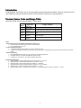
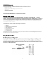
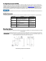
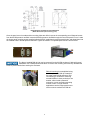
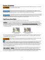
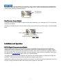
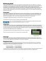
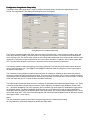
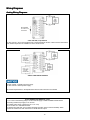
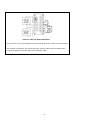
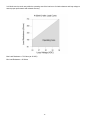
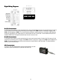
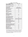
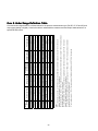
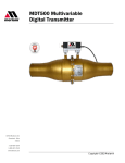
User’s Manual 9R101-E
June 2012
M1500 Digital Pressure
Transmitter
User’s Manual
The Meriam Process Technologies (Meriam) Model M1500
Digital Pressure Transmitter is a compact, NIST traceable,
precision measurement instrument available in a wide variety of
pressure ranges and communication / output options. Models
are available for differential, gauge, compound and absolute
pressure measurements. Output options include analog (420mA, 0-5V and two SPST switches) or digital (RS-232, RS485 or USB) models. Communication with digital M1500’s is
achieved using Meriam Serial Protocol (MSP), the Meriam DLL
or LabVIEW®. Digital units have an option of dual pressure
sensors in one unit (any non-differential pressure combination).
Personal computer (PC) configuration software is included. The
software can be used to configure digital transmitters for use
and is required to set up analog transmitter models.
1
Safety Information
Failure to follow all instructions could result in injury. Read, understand and follow all safety warnings
and instructions provided with this product. Also, meet or exceed your employer’s safety practices.
In no event shall Meriam be liable for any indirect, special, incidental, consequential or punitive damages or
for any lost profits arising out of or relating to any services provided by Meriam or its affiliates. It is not possible for
Meriam to identify all foreseeable uses/misuses, therefore all persons involved in commissioning, using or maintaining
this product must satisfy themselves that each intended application is acceptable.
Safety Warnings
The table below defines the safety symbols, signal words and corresponding safety messages used in the manual to
identify potential hazards and are intended to warn persons about hazards that could result in personal injury or
equipment damage.
This is the Read Instruction Manual symbol. This symbol indicates
that you must read the instruction manual.
This is the Safety Alert symbol. This symbol indicates a WARNING. Warnings alert you to actions that can cause personal
injury or pose a physical threat. Please read these carefully.
This is the Safety Glasses symbol. This symbol indicates that you must wear approved safety glasses during the task.
This is the Safety Gloves symbol. This symbol indicates that you must wear approved safety gloves during the task.
Indicates a potentially hazardous situation which, if not avoided, will result in death or serious injury.
Indicates a potentially hazardous situation which, if not avoided, could result in death or serious injury.
Indicates a potentially hazardous situation which, if not avoided, could result in minor or moderate injury.
Indicates information essential for proper product installation, operation or maintenance.
Information in this document is subject to change without notice. Check the Meriam web site (www.meriam.com) for latest
manual revision.
For customer assistance please call your local Meriam representative or Meriam directly.
Meriam Process Technologies
10920 Madison Avenue
Cleveland, Ohio 44102
Telephone: (216) 281-1100
Fax: (216) 281-0228
E-mail: [email protected]
Web: www.meriam.com
LabVIEW® is a registered trademark of National Instruments
Viton® is a registered trademark of DuPont
2
Table of Contents
Certification/Safety/Warnings........................................................ 1
Introduction.................................................................................... 2
Pressure Sensor Code and Range Table ..................................... 2
CD ROM Resources...................................................................... 3
Meriam Setup Utility ...................................................................... 3
PC / M1500 Interface .................................................................... 3
For Analog Output Configuration .............................................. 3
For Digital Communication ....................................................... 4
Interface Accessories ............................................................... 4
Mounting Options .......................................................................... 4
Pressure Connections ................................................................... 6
Single Pressure Sensor Models ............................................... 6
Dual Pressure Sensor Models .................................................. 7
Installation and Operation ............................................................. 7
M1500 Digital Communication Models ..................................... 7
RS-485.................................................................................. 8
USB....................................................................................... 8
M1500 Analog Models .............................................................. 9
Current Output ...................................................................... 9
Voltage Output...................................................................... 9
Switch Output ....................................................................... 9
Wiring Detection Feature ...................................................... 9
Configuration Using Meriam Setup Utility............................. 9
Zeroing the M1500.................................................................. 12
Zeroing Analog M1500s: non-Absolute models.................. 12
Zeroing Analog M1500s: Absolute Pressure Models ......... 12
Zeroing Digital M1500s (non-Absolute models) ................. 12
Zeroing For Mounting Position ........................................... 12
Zeroing DI Models For Static Pressure Effect .................... 12
Wiring Diagrams.......................................................................... 13
Analog Wiring Diagrams ......................................................... 13
Digital Wiring Diagrams .......................................................... 16
RS-232 Communication...................................................... 16
RS-485 Communication...................................................... 16
USB Communication .......................................................... 16
Recertification and Recalibration ................................................ 17
Firmware Reflash ........................................................................ 18
Firmware Features ...................................................................... 18
Over & Under Range Definition Table......................................... 20
Service and Calibration ............................................................... 21
Specifications .............................................................................. 22
3
User’s Manual 9R101-E
June 2012
Certification/Safety/Warnings
Fire/Explosion Hazard. This instrument is not intrinsically safe. DO NOT use or service in areas
that may contain flammable gas or vapors, combustible dusts or ignitable fibers where an
unintended spark can cause a fire/explosion.
Do not exceed the Pressure Limits listed in the Specifications section of this manual. Failure to
operate within the specified pressure limit could result in death or serious injury.
Do not exceed the Maximum Input Voltage listed under “Power Requirements” in the Specification section of this
manual
For Analog output units, do not exceed the Switch Rating listed under “Analog Outputs” in the Specifications
section of this manual.
Disconnect power before servicing.
Substitution of components may impair operation and safety.
Do not connect to AC power; use only with DC supply.
1
Introduction
Congratulations! The M1500 is one of the most capable pressure transmitters available. Follow the instructions in this
User’s Manual to set up the M1500 to perform to its full potential. Thank you for choosing Meriam.
Pressure Sensor Code and Range Table
Model No. M1500-“Sensor Code with Range” 1 shown below:
Sensor
3
Code
DNxxxx
DIxxxx
GIxxxx
CIxxxx
AIxxxx
Application
Differential,
Non-isolated
Differential,
2
Isolated
Gauge, Isolated
Compound,
Isolated
Absolute,
Isolated
Ranges Available
0 – 0010, 0028, 0200, 0415, 2000" H2O
0 – 0001, 0005, 0015, 0030, 0100, 0300, 0500 PSID
0 – 0015, 0030, 0050, 0100, 0300, 0500, 1000, 3000
PSIG
-14.7 to +0015, 0030, 0050, 0100, 0300, 0500,
1000, 3000 PSIG
0 – 0017, 0038, 0100, 1000 PSIA
Notes:
1
Dual Pressure Sensor Units (digital communications option only)
M1500-“Sensor Code with Range”-“Sensor Code with Range”
Any combination of GI, CI or AI
2
DI Pressure Manifold Options
2-port DIxxxx manifolds are standard; use for clean liquid service only
4-port DIxxxx flushing manifolds are order options; best for dirty liquids, congealing liquids, and liquids with particulates or suspended
solids
3
Media Compatibility
Non-isolated DN sensors: clean, dry, non-corrosive, non-condensing gases only
®
Isolated DI sensors: any media compatible with 316SS & Viton
Isolated GI, CI & AI sensors: any media compatible with 316SS
Model Number Examples:
1. ZM1500-DN0415 = M1500, Differential Pressure, Non-isolated, 0 – 415” H2O
2. ZM1500-DI0030 = M1500, Differential Pressure, Isolated, 0 – 30 PSI
3. ZM1500-GI1000 = M1500, Gauge Pressure, Isolated, 0 – 1000 PSIG
4. ZM1500-CI0100= M1500, Compound Pressure, Isolated, -14.7 to +100 PSIG
5. ZM1500-AI0017 = M1500, Absolute Pressure, Isolated, 0 – 17 PSIA
6. ZM1500-GI0030-AI0017 = Gauge Pressure, Isolated, 0 – 30 PSIG and Absolute Pressure, Isolated, 0 – 17 PSIA
2
CD ROM Resources
Each M1500 comes with a product CD ROM that includes the following resources:
- Meriam Setup Utility
- Meriam Serial Protocol (MSP) Implementation Guide
- USB Drivers
- LabVIEW® Drivers (VIs)
Please make use of these resources as referenced in this manual.
Meriam Setup Utility
The M1500 Meriam Setup Utility runs on Microsoft Windows® XP, Windows® Vista and Windows® 7 operating
systems. Place the CD in the PC’s CD ROM drive and install the software using the installation utility. The software is
used to configure M1500 Digital Transmitters by setting engineering units, damp rate and other parameters, to zero
the unit, or to set the output span on analog units. See the “PC Interface” section of this manual for information on
connecting the M1500 to a host PC.
The Software user interface provides the following user selections:
1.)
2.)
3.)
4.)
5.)
6.)
Startup
Measurement and Configuration
Set Analog Output
Transmitter Information
Reflash Firmware
Field Recalibration
The Software provides user instruction and / or drop down selection boxes once the desired option is selected. See
the Software’s HELP feature for more details.
PC / M1500 Interface
For Analog Output Configuration
To configure an M1500 with analog output, connect the unit to a host PC using a USB type A to USB type mini-B
cable as shown in the diagram below. The USB connection will power the M1500 and provide communication for
configuration setup when connected to high power (500 mA) USB ports or powered USB hubs. Open the M1500
Meriam Setup Utility application to configure the transmitter as desired. See the “Installation and Operation” section of
this manual for additional information.
3
For Digital Communication M1500s
Connect the M1500 to a host PC, using the RS-232, RS-485 or USB connections provided. See the “Digital Wiring
Diagrams” section of this manual for more details. Use the M1500 Meriam Setup Utility to configure the transmitter or
use MSP commands (see protocol documentation on the product CD or at www.meriam.com under Resources /
Application Notes). The M1500 pressure default network address is 40 (0x28 Hex) and module address is 64 (0x40
Hex) for MSP and LabVIEW®. See the “Installation and Operation” section of this manual for additional information.
USB drivers must be installed on the host PC prior to communication with M1500 USB models. Find these drivers on
the product CD.
Interface Accessories
The following table lists part numbers for various accessories available to assist in configuration or communication.
Part Number
Z9A000003PN06
Z9P273
RS-232 to RS-485 Converter, PC Mount,
port powered
Z7621-1
Z7621
ZA900447-00052
Z9R111
Description
M1500 Product CD ROM
USB type A to USB type mini-B cable–
used with analog output M1500s to
interface with PC & configuration software
RS-232 to RS-485 Converter, DIN rail
mount, externally powered
DB-9 Cable, male x female – optional
accessory
Meriam Serial Protocol Implementation
Guide
Accessory Status
Standard, all models
Optional for analog
models, initial set up
& support
Optional for RS-485
models initial set up
& support
Optional for RS-485
multi-drop networks
Option for RS-232
and RS-485 support
On CD and available
at www.meriam.com
Mounting Options
M1500 mounting options include panel and DIN rail mount. Both are standard on all models and hardware is included
with shipment.
Panel mounting is achieved using the cut out and mounting hole guides below. Plan the mounting hole locations so
the P1 (HI) and P2 (LO) ports will be in the desired position upon completion. The four Port Manifold template is only
used for M1500-DIxxxx models with optional flushing ports.
Panel Mounting Template for 2 Port Manifold
4
Panel Mounting Template for 4 Port Manifold
(M1500-DIxxxx with optional flushing ports)
Once the panel cut out is made and the mounting holes are drilled, remove the corresponding set of diagonal screws
from the M1500 pressure manifold. Insert the M1500’s pressure manifold through the rear of the panel cut out. Locate
the longer panel mounting screws supplied with the M1500, install them through the panel holes, and thread them into
the vacated holes in M1500 pressure manifold. Tighten as needed. A completed panel mount is shown below.
The factory installed DIN rail clip may be removed from the M1500 enclosure if desired for panel
installation. Use a Phillips head screw driver to remove the mounting screw and clip. Reinstall the
screw to prevent debris from entering the enclosure.
DIN rail mounting is accomplished using
the factory-installed DIN clip located on
the edge of the M1500 enclosure. DIN
rail mounting is excellent for mounting
several M1500s in close proximity to one
another, either inside a protective
enclosure, or on a convenient mounting
surface or wall. For high vibration
applications use the longer panel mount
screw to secure enclosure to DIN rail.
5
Pressure Connections
Failure to keep pressure below specified limits could result in death or serious injury. See section
– Specifications of this manual.
All pressure connections are 1/8" NPT (female). A wrench should be used on the flats of the
pressure manifold to hold it securely and prevent accidental damage when installing or removing a
pressure fitting. Use suitable thread tape or thread sealing compound for leak-free connections.
3-valve equalizing manifolds are recommended for differential pressure units to prevent accidental
damage while installing or commissioning M1500-DN and -DI transmitters and to support zeroing
procedures. See the Specifications section of this manual for pressure limit information on differential and other
pressure types. See the Zeroing section for information on zeroing the M1500.
Single Pressure Sensor Models
Single pressure sensors are available in all M1500 pressure and output types.
Differential pressure types, DN and DI models, have two pressure ports in the 316L SS manifold. The ports are
engraved P1 (HI connection) and P2 (LO connection). Connect the application high pressure to the P1 port and the
low pressure to the P2 port for differential applications. For Vacuum applications using differential models, vent the P1
port to atmosphere and connect the vacuum line to the P2 port. Note that the output of the M1500 in this vacuum
configuration will transmit “positive” values. The receiving device will need to be configured to add the negative sign (
- ) to the received value.
DN & DI Standard Manifold
P1 = HI, P2 = LO
DI Optional Flushing Manifold
P1 = HI, P2 = LO
DI models are available with optional flushing ports to allow flushing the manifold interior (see graphic at right above).
This is desirable for dirty liquids, liquids with particulates or suspended solids, or congealing liquids. Use solvents
compatible with 316SS and Viton only.
Spray hazard. Wear approved safety glasses and impermeable gloves. DO NOT pressurize the
system; failure to follow these instructions could result in death or serious injury.
The flushing ports, an available option on DI models, are linked by internal passages to their respective P1 or
P2 port. If a cleaning solvent is injected into one port it will flow through the manifold and the solvent will exit
from the connected port. DO NOT pressurize the cleaning solvent as spray or stream flow could occur. Meriam
recommends using a solution recovery system to capture the used cleaning solution. See the Specification section of
this manual for fitting details and wetted parts material. Refer to the solvent manufacturer’s Material Safety Data
Sheet for safe handling information.
Gauge, Compound and Absolute pressure types in single sensor M1500 Digital Transmitters use the pressure port
marked P1 on the manifold. Gauge pressure measurements are referenced to atmospheric pressure inside the
enclosure and measure from 0 to the full scale range. Compound units are gauge units that measure down to full
vacuum (approximately -14.7 PSIG) as well as up to the positive full scale range. Absolute pressure measurements
are internally referenced to a complete vacuum on the P2 side of the pressure sensor. See drawing below.
6
A second pressure port is present on single sensor models but has been factory sealed with an
appropriate venting plug. Do not remove the plug for any reason. GI, CI, and AI units cannot be converted to other
pressure types in the field. See drawing below.
Permanent plug.
Do Not Remove
GI, CI and AI Manifold
Dual Pressure Sensor Models
Dual pressure sensors are available for digital communication models only. Any combination of GI, CI or AI sensors
can be accommodated.
Dual pressure models use the P1 port for pressure sensor 1 and the P2 port for pressure sensor 2. See the example
below.
AI0017
GI0030
Dual Pressure Sensor Manifold
Example: Model M1500-AI0017-GI0030
P1
P2
Installation and Operation
M1500 Digital Communication
Communication Models
Models
Digital communication delivers the best possible accuracy to compatible receiving devices. M1500 models are
available with RS-232, RS-485 and USB. PC configuration software is included with shipment to support set up of
engineering unit, damp rate and other parameters and functions. Send / receive functions are supported by MSP, a
DLL and LabVIEW® VIs. To program your system using these protocols, see the resources available on the product
CD ROM and at www.meriam.com under “Resources / Application Notes”.
The M1500 pressure default network address is 40 (0x28 Hex) and module address is 64 (0x40 Hex) for MSP and
LabVIEW®. USB units have communication port addresses assigned by the host PC.
Digital M1502 models have two pressure sensors in one enclosure. The sensors can be any combination of GI, CI or
AI types. A single command from MSP returns both pressure signals from the M1502.
7
RSRS-232
RS-232 is used for point-to-point communication. The M1500 is powered through the terminal block and uses a DB-9
(female)
connector or terminal block for digital communication. Terminal labels follow RS-232 standard
TIA/EIA-232. See the Wiring
Diagrams section for details.
RSRS-485
RS-485 communication is best for
multipoint networks. The M1500 can
be powered and communicated with
RS-232 / RS-485 Connector
using either the terminal block or the DB-9 pin outs for half-duplex communication. See the Wiring Diagrams section
for details.
USB
High power USB ports supply power for
this M1500 version and can be used for
point-to-point interface with a PC port or
for multiple interfaces using externally
powered USB hubs. The M1500 uses
a standard USB type B connector.
USB Connector
USB drivers for the M1500 must be installed on the host PC prior to communication. These drivers are on the product
CD ROM.
M1500 with USB will not work using low power USB ports; examples are keyboard USB and
unpowered USB hubs. Use the M1500 with high power (500 mA) USB ports only and powered
USB hubs only.
8
M1500 Analog
Analog Models
Analog units are set up in the field using the supplied M1500 Meriam Setup Utility and a USB type A to USB type
mini-B cable. Power is provide over the USB cable for setup operations. The LED on the base of the transmitter will
blink red when only the USB cable is connected. The Meriam Setup Utility software supports pressure zero,
configuration of the output type and output span, plus selection of engineering units, damp rate and other parameters
(see the Firmware Features section of this manual for more details). Load the software on a suitable PC and use
optional p/n Z9P273 USB cable to connect the PC to the M1500’s USB port. Set up the transmitter as desired using
the Meriam Setup Utility.
Current Output
The M1500’s 4-20 milliAmpere (mA) output can be used with 2-wire loop power or in a 4-wire configuration. 2-wire
power supplies should be 24-36 VDC (60 mA minimum). The 4-wire loop power supply should be an isolated type
(floating ground), 24-36 VDC (60 mA minimum) and the external supply should be 12-36 VDC (60 mA minimum).
Minimum loop impedance is 50Ω. See the Wiring Diagrams section and connect as appropriate.
The NAMUR low/high saturation limits for 2-wire and 4-wire current mode is 20.5mA.
The 20mA value can be set over a 4:1 turndown of the transmitters URL.
For 4- wire commissioning always connect the external supply to the PWR and GND terminals
before connecting the isolated loop supply to LP+ and LP–.
Voltage Output
Voltage output is 0-5 V DC but can be configured using the Meriam Setup Utility for any output span (for example, a
1-5V span may be more convenient for some applications). The voltage output uses a 4-wire system and requires a
12-36 VDC (60 mA minimum) power supply. The M1500 will draw a maximum of 10 mA from the power supply. See
the Wiring Diagrams section for details. The M1500 Transmitter can drive an output load having an impedance of 10K
ohms or more in parallel with up to 1µF of capacitance.
The low/high saturation limits for voltage mode are 0.0V and 5.1V respectively.
The 5V DC value can be set over a 4:1 turndown of the transmitters URL.
Analog Connector
Switch Output
Two solid state, opto-coupler, polarity independent, SPST switches are included on Analog output models of the
M1500. The opto-couplers are low power, rated for 80V DC and 100 mA max. Their use is limited to 4-wire 4–20 mA
or 4-wire 0–5 VDC options only (not available for 2-wire 4-20 mA operation).
Wiring Detection Feature
The M1500 has a wiring detection feature that is active for the first five (5) minutes after power up. Complete the
output wiring within the 5 minute period for proper operation. If wiring is not completed in the allotted time, simply
cycle power to re-activate the wiring detection sequence.
2-wire 4-20mA wiring
2 green LED blinks
4-wire 0-5Voltage wiring 3 green LED blinks
4-wire 4-20mA wiring
4 green LED blinks
If a fault condition occurs after the initial 5 minute period (e.g. output wiring changed, voltage drops below minimum or
climbs above maximum specified value), the green LED blink sequence will change to a red sequence.
9
Configuration Using Meriam Setup Utility
The Meriam Setup Utility application is used to configure the analog output as well as the digital outputs of the
M1500. The image below is the analog setup dialog box from the program.
Analog Setup Screen from Meriam Setup Utility
The Pressure groupbox displays the upper and lower sensor limits (LSL/USL), current pressure reading, upper and
lower range values (LRV/URV), minimum span for the range and a Zero button. The sensor limits are fixed values
which are factory set. The sensor range values are user configurable parameters which must meet the minimum span
requirement. The minimum span is specified as 25% of the sensor limit delta. In addition, URV must be greater than
LRV. The zero button allows the user the zero the sensor at the current pressure measurement.
The Output groupbox contains the output type and range selections. The Volts and Current radio buttons allow the
user to select the output type. The AO@LRV and AO@URV edit fields scale the voltage or current output signal to
the pressure input range.
The Transmitter Alarm groupbox contains a selection button for enabling or disabling an alarm when the pressure
sensor has reached its hard over/under range limits. This occurs when the sensor can no longer compute a pressure
measurement. When enabled and an alarm is detected, the output will go to 22.5mA when in current mode. In voltage
mode, the output will go to 5.1V when the alarm condition is detected.
The Digital Output groupboxes allow the user to configure the parameters associated with Digital Output 1 & 2. These
include the Output action (Closed, Open or Inactive), Value setpoint(s), Comparison type (Between, Greater Than,
etcT) and Reset Deadband. The Value setpoint(s) and comparison type work together to establish the trigger points
for the digital outputs. The Reset Deadband determines the amount of hysteresis around the Value setpoint(s) to
eliminate continuous toggling of the digital outputs at the trigger points. The minimum Reset Deadband is 0.5% of the
sensor limit range (USL - LSL). If there are two setpoints, the maximum Reset Deadband is half of difference between
them (Upper Value – Lower Value).
Notes:
The user parameters (pressure) are entered in engineering units of the measurement module.
All user parameters entered are validated by the Meriam Setup Utility.
10
Examples:
1. Digital Output 1 is set up as shown in Meriam Setup Utility.
Output action = Closed
Comparison type = Between
Lower Value = 0.4000 PSI
Upper Value = 3.5000 PSI
Reset Deadband = 0.0750 PSI
As the pressure increases from 0 PSI the switch will remain open until the pressure reaches the Lower Value
setpoint (0.4 PSI) at which point it will close. As the pressure continues to rise the switch will remain closed
until the pressure reaches the Upper Value setpoint plus the Reset Deadband (3.5 + 0.075 = 3.575 PSI) at
which point it will open.
Now the pressure begins to decrease. The switch will remain open until the pressure reaches the Upper
Value setpoint (3.5 PSI) at which point it will close. As the pressure continues to decrease the switch will
remain closed until the pressure reaches the Lower Value setpoint minus the Reset Deadband (0.4 - 0.075 =
0.325 PSI) at which point it will open.
2. Digital Output 2 is set up as shown in Meriam Setup Utility.
Output action = Open
Comparison type = Greater Than
Value = 0.4000 PSI
Reset Deadband = 0.0750 PSI
As the pressure increases from 0 PSI the switch will remain closed until the pressure reaches the Value
setpoint (0.4 PSI) at which point it will open. As the pressure continues to rise the switch will continue to
remain open since the comparison says the pressure must be Greater Than the Value setpoint for the output
action to occur.
Now the pressure begins to decrease. The switch will remain open until the pressure reaches the Value
setpoint minus the Reset Deadband (0.4 - 0.075 = 0.325 PSI) at which point it will close.
11
Zeroing the M1500
M1500
Meriam recommends zeroing the M1500 prior to use for DN, DI, GI and CI models and periodically thereafter as
needed. AI models normally do not need to be zeroed prior to initial use. Two types of zeroing are supported:
1. Pressure Zero: This recommended method takes a “snapshot” of the measured pressure when the M1500
is vented to atmosphere for DN, DI, GI and CI models or, in the case of AI models, when a vacuum of less
than 100 microns absolute is applied.
M1500 DN, DI, GI and CI models can be zeroed only when the newly applied zero is within
±5% FS. This prevents accidentally zeroing at relatively high offset pressures. If outside the
±5% FS limit, an error message is given and the manometer does not zero. The AI model limit
is 100 microns absolute.
2. Factory Zero: This method restores the calibration curve to the original zero taken at the factory.
The Factory Zero feature is intended for comparison purposes only. Factory Zero
should not be used as a reference for actual pressure measurement because zerodrift occurring after shipment from the factory would not be accounted for.
Zeroing Analog M1500s:
M1500s: nonnon-Absolute models
Use the Meriam Setup Utility to zero analog versions of the M1500. Follow the “PC / M1500 Interface - For Analog
Configuration” section of this manual to connect the M1500 to a host PC. Open the Meriam Setup Utility, set the
appropriate Com Port and click on the Measure / Configure button. Vent all M1500 pressure connections to
atmosphere and wait several seconds for stabilization. Then click the Zero button on the software. To access the
Factory Zero control, click on the Field Re-Calibration button on the opening page of the software.
Zeroing Analog M1500s: Absolute Pressure Models
M1500-AI models are re-zeroed using the Meriam Setup Utility. Reset to Factory Zero using the appropriate
controls in the Meriam Setup Utility. To take a new pressure zero, apply a vacuum of less than 100 microns
absolute. Then select the Zero button from the Utility.
Zeroing Digital M1500s (non(non-Absolute
Absolute models)
models)
A pressure zero or factory zero command is used to zero digital M1500’s using MSP (see the MSP Implementation
Guide on the product CD) or LabVIEW commands. Be sure to vent all M1500 pressure connections to atmosphere
and wait several seconds for stabilization before sending zero command.
Zeroing For Mounting Position
Meriam recommends zeroing the M1500 in its final mounting position to null any orientation
effects caused by fill fluid in DI, GI, CI or AI models or by protective silicon gel in the case of
DN models. Effects are relatively small for all but DI models. DI models are sensitive about the roll axis but when
mounted in the final position and zeroed, DI models are very stable and accurate to the specification listed in this
manual.
Zeroing
Zeroing DI Models For Static Pressure Effect
M1500-DI models are available in measurement ranges from 1 to 500 PSID for common
mode static pressures up to 1000 PSID. The zero reading on these units is offset in a uniform
way by the static pressure of the service. The offset is easily zeroed out using the M1500 zeroing command.
Meriam recommends applying normal static pressure to the subject M1500-DI using a 3-valve equalizing
manifold. The M1500-DI should be zeroed under normal static pressure conditions with the equalizing valve open.
12
Wiring Diagrams
Analog Wiring Diagrams
Not Available
for 2-wire 4-20
mA service.
Can be placed
on either side of
the loop.
2-wire 4-20 mA, Loop Powered
24 VDC nominal – see “Power Requirements” in the Specifications section of this manual for more detail
Note: Switch outputs are not available in 2-wire 4-20 mA service.
4-wire 4-20mA with Switches
24 VDC nominal – lsolated loop power supply
12 VDC nominal – External power supply
see “Power Requirements” in the Specifications section of this manual for more details
4-wire 4-20mA with Switches, con’t
1. For 4-wire commissioning always connect external supply to PWR and GND terminals before
connecting isolated loop supply to LP+ and LP–.
2. Isolated power supply is required for LP+ / LP– loop.
3. Do not short LP– and GND terminals.
4. Switches are solid state, opto-couplers with SPST operation (Clare model CPC1008N). Switch
circuits are isolated from each other and from the M1500 mA output.
13
4-wire 0-5 V DC with Optional Switches
12 VDC nominal – see “Power Requirements” in the Specifications section of this manual for more detail
Note: Switches are solid state, opto-couplers with SPST operation (Clare model CPC1008N). Switch
circuits are isolated from each other and from the M1500 mA output..
14
In 4-20mA two-wire mode, stay within the operating area of the load curve for load resistance and loop voltage to
assure proper performance and maintain accuracy.
Max Load Resistance = 753 Ohms (at 36 VDC)
Min Load Resistance = 50 Ohms
15
Digital Wiring Diagrams
RS-485 B(-)
RS-485 A(+)
RS-232 RX
RS-232 TX
5 4 3 2 1
9 8 7 6
DB9 Pin Out
1
2
3
5
RS-232
GND
RX
TX
GND
DCE
--Out
In
---
Vin(8-36V)
GND
Chassis GND
RSRS-232
232 Communication
For RS-232 communication use the terminal block for power and the DB-9 connector for communications. Provide 836 VDC power (20 mA minimum) by connecting to the +supply to the PWR+ terminal. Connect the –supply to the
PWR- terminal adjacent to PWR+. For communications connect the receiving device to the M1500’s DB-9 (female)
serial port (see DB-9 Pin Out Table above) or to the M1500’s RX and TX terminals. Terminal labels follow RS-232
standard TIA/EIA-232.The digital interface draws 20 mA of current or less.
RSRS-485 Communication
For RS-485 communication use the terminal block for power and communication. Provide 8-36 VDC power (20 mA
minimum) by connecting to the +supply to the PWR+ terminal. Connect the –supply to the PWR- terminal adjacent to
PWR+. For communications connect the receiving device to the M1500’s A and B terminals. The digital interface
draws 20 mA of current or less.
USB Communication
Connect to the USB type B female connector of the M1500. Use with
high power (500 mA) USB ports or powered USB hubs only.
16
Recertification and Recalibration
Meriam recommends annual calibration check and recertification for the M1500. Contact Meriam for this service.
Periodic recalibration of M1500 Digital Pressure Transmitters may be necessary to maintain optimum performance.
Meriam can also provide this service.
The M1500 does support field recalibration through the Meriam Setup Utility provided on the product CD ROM.
Connect the PC to the M1500 according to the “PC / M1500 Interface” and “Installation and Operation” sections of
this manual. Install the software as directed by the CD instructions on a suitable PC. Select the Field Recalibration
Interface button and follow the directions provided by the software.
Field recalibration should only be executed by qualified personnel using suitable reference standards. These
standards should meet the accuracy requirements of your company or industry. Meriam recommends using primary
standards at least four times more accurate than the unit under test.
For pressure transmitters up to 200 PSI, Meriam recommends a deadweight tester of at least ±0.0015% of reading for
field recalibration. For transmitter ranges of 200 PSI and above, use a deadweight tester of at least ±0.0030% of
reading. When calibrating using a dead weight tester referenced to inches of water, be sure the M1500’s inches of
water reference temperature matches that of the dead weight tester’s calibration data.
17
Firmware Reflash
Meriam periodically issues new operating firmware to improve M1500 operation and features. All M1500 units can be
reflashed with new firmware using the Meriam Setup Utility.
To install new firmware, save the new firmware file to a known location on a host PC with Internet connection. Follow
the “PC / M1500 Interface” instructions in this manual, for analog or digital output versions as appropriate, and
connect the M1500 to the host PC. Open the Meriam Setup Utility, set the appropriate Com Port and click on the
Reflash Firmware button. Follow the instructions set that appear to reflash the M1500 with the latest firmware version.
Firmware Features
Programming features supported through Meriam Serial Protocol (MSP) and DDL are listed in the table below. See
the Meriam Setup Utility or the MSP Implementation Guide for more information on using programming features and
information commands.
18
Feature / Command Table
19
20
Certified Measurement Range
0 to 100% FS
4.0 to 20.0 mA
0 to 100% FS
0 to 100% FS
4.0 to 20.0 mA
0 to 100% FS
3
0 to 100% FS
-20 to 0% FS
3.5 to 4 mA
4.0 to 20.0 mA
Value + Status 32
0 to 100% FS
4
0 to 100% FS
NA
4 mA @ -14.5 PSIG
4.0 to 20.0 mA
No value + Status 33
0 to 100% FS
5
0 to 100% FS
NA
4 mA @ 0 PSIA
4.0 to 20.0 mA
No value + Status 33
0 to 100% FS
Soft Under Range
-20 to 0% FS
3.5 to 4 mA
Value + Status 32
-20 to 0% FS
3.5 to 4 mA
Value + Status 32
Soft Over Range
100 to 120% FS
20 to 22 mA
Value + Status 32
100 to 120% FS
20 to 22 mA
Value + Status 32
100 to 120% FS
20 to 22 mA
Value + Status 32
100 to 120% FS
20 to 22 mA
Value + Status 32
100 to 120% FS
20 to 22 mA
Value + Status 32
Hard Over Range
> 120% FS
22 mA
No value + Status 33,17
> 120% FS
22 mA
No value + Status 33,17
> 120% FS
22 mA
No value + Status 33,17
> 120% FS
22 mA
No value + Status 33,17
> 120% FS
22 mA
No value + Status 33,17
5
AI units will measure to +120% of full scale pressure. Calibration certification is for 0 PSIA to full scale only.
DN units will measure to -20% (or -10 PSID, whichever is greater pressure relative to absolute zero) and +120% of full scale
pressure. Calibration certification is for 0 – full scale only.
2
DI units will measure to -20% (or -150 PSI, whichever is greater pressure relative to absolute zero) and +120% of full scale pressure.
Calibration certification is for 0 – full scale only.
3
GI units will measure to -20% (or -10 PSIG, whichever is greater pressure relative to absolute zero) and +120% of full scale
pressure. Calibration certification is for 0 – full scale only.
4
CI units will measure to negative barometric pressure (typically -14.7 PSIG) and to +120% of full scale pressure. Calibration
certification is for -14.5 PSIG to full scale only.
1
Notes:
5
AI Pressure
NA
Analog
4 mA @ 0 PSIA
Digital No value + Status 33,16
4
CI Pressure
NA
Analog
4 mA @ -14.5 PSIG
Digital No value + Status 33,16
3
GI Pressure
< -20% FS
Analog
3.5 mA
Digital No value + Status 33,16
2
DI Pressure
< -20% FS
Analog
3.5 mA
Digital No value + Status 33,16
Sensor
Output
Hard Under Range
1
DN Pressure
< -20% FS
Analog
3.5 mA
Digital No value + Status 33,16
Over & Under Range Definition Table
Over and under range behavior is defined below for the pressure measurement type (DN, DI, GI, CI and AI) and
output type (analog or digital). Consult the table to understand the measurement and output characteristics of a
specific M1500 model.
Service and Calibration
In the event an M1500 requires service or needs to be returned for factory recertification or re-calibration, please
contact Meriam at the numbers listed below.
DO NOT send any unit in for service without first contacting Meriam for a Return Material Authorization
(RMA) number. If this number has not been obtained and clearly marked on the return packaging, the unit will
be returned at the shipper’s expense. An RMA number will be provided by the Meriam Repair Department when
you call, fax or e-mail your information. Certification for Non-Hazardous Materials will also be required. The RMA
number must accompany all incoming packages to insure proper tracking, processing and repair work.
To assist us in processing your service request, please have the Model & Serial Number of the unit available when
you call. This information is located on the product label.
Meriam Process Technologies
10920 Madison Avenue
Cleveland, Ohio 44102
TELEPHONE: (216) 281-1100
FAX:
(216) 281-0228
E-mail: [email protected]
Web Site:
www.meriam.com
21
Specifications
NIST Traceable Accuracy
Digital: ± 0.025% of FS including all affects of linearity, repeatability, hysteresis and temperature*
Analog: ± 0.035% of FS including all affects of linearity, repeatability, hysteresis and temperature*
The DN0010 sensor accuracy is:
Digital: ± 0.050% of FS
Analog: ± 0.056% of FS
*Temperature Performance: Accuracy statement includes all affects of temperature from -20º to +50º C (-4º to
+122º F)
Update Rate, Single pressure sensor: 14 samples per second
Update Rate, Dual pressure sensors: 7 samples per second
Engineering Units: 32 user selectable units, two user defined units
Pressure Limits
DN sensors: 2x range when pressurized on P1 (HI) side only, 150PSI when applied simultaneously to P1 (HI) and P2
(LO) sides.
DI sensors: 3x range when pressurized on P1 (HI) side only, 3x range or 150 PSI (whichever is less) on P2 (LO)
side only 1000 PSI when applied simultaneously to P1 (HI) and P2 (LO) sides.
GI, CI, AI sensors: 2x range
Zeroing limits
DN, DI, GI and CI sensors: ±5% FS
AI sensors: 100 microns (absolute zero reference)
Media Compatibility
DN sensors:
Non-isolated for clean, dry, non-corrosive, noncondensing gases only (Brass, 316L SS, Silicon gel)
DI sensors:
Isolated for fluids compatible with 316L SS & Viton®
(standard)
GI, CI, AI sensors: Isolated for fluids compatible with 316L SS
Digital Communication: Meriam Serial Protocol, DLL or LabVIEW®
RS-232: 19200 baud (adj.), 8 data bits, 1 stop bit, no parity.
RS-485: Half duplex, 3-wire (A, B, GND), 19200 baud (adjustable), 1 start bit, 1 stop bit, no parity. Multidrop
addressing with up to 255 devices using Meriam Serial Protocol.
USB: USB 2.0
Analog Outputs
Current: 4–20 mA, 2-wire loop powered or 4-wire systems, minimum loop impedance is 50Ω
Voltage: 0–5 VDC, 4-wire
Switches: 2 each, solid state opto-coupler SPST switches
Rated for 80V DC, 100 mA max.
For use 4-wire 4–20 mA or 4-wire 0–5 VDC only.
Connections
P1 & P2 Pressure Ports: 1⁄8” NPT (female)
Flushing Ports: 5/16 – 24 SAE/MS J1926 (316L SS plugs included)
Electrical / Communication
Power: 7 position terminal block (1.3 mm diameter holes suitable for 16 – 25 gauge solid or stranded wire)
RS-232: DB-9 (female) connector or 7 position terminal block
RS-485: DB-9 (female) connector or 7 position terminal block
USB: type B female connector
Analog: 7 position terminal block (two each), 4 position terminal block & USB mini-B
22
Power Requirements by Communication / Output Type
RS-232, RS-485: 8 – 36 VDC max., 20 mA min.
USB: high power (500 mA) USB port or USB hub (PC USB ports and USB hubs with power adapters are typically
high power)
mA, 2-wire: 24 – 36 VDC max. (24 VDC recommended), 60 mA min.
mA, 4-wire: isolated loop supply of 24 – 36 VDC max., 60 mA min.
external power supply of 12 – 36 VDC max., 60 mA min.
V, 4-wire: 12 – 36 VDC max., 60 mA min.
Note: To achieve best accuracy use a power supply(s) with equal or better specifications as the Agilent E3630A:
Ripple & Noise from 20 Hz to 20 MHz
Normal Mode Voltage rms: 350 µV
Peak to Peak: 1.5 mV
Load and Line Regulation:
0.01% + 2 mV
Enclosure: 4.625” L x 2.125” W x 1.25” H, Aluminum case, 316LSS pressure manifold, IP40 rating
Weight: 10.5 oz for DN, GI, CI or AI pressure types, 16 oz for DI type
Mounting: Panel and DIN rail mounting hardware are standard
Temperature Limits
Operating: -4 to 122°F (-20 to 50°C)
Storage: -40 to 185°F (-40 to 85°C)
Humidity Limits: 5 – 95% RH
Shock: 30 g peak, half-sine, 11ms pulse (tested in accordance with IEC-60068-27)
Vibration: 5 to 2000 Hz, 6.0 grms (tested in accordance with IEC-60068-27)
Certifications: CE Mark
23