1
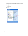
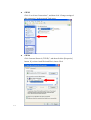
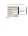
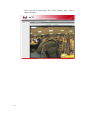
Encoder Firmware
A1D-220-V3.10.22-AC
User’s Manual
i
Table of Contents
1.
INSTALLATION _______________________________________________ 1-1
1.1
Minimum System Requirements ___________________________________ 1-1
1.2
Preparation before setup _________________________________________ 1-2
1.2.1
1.3
Setup your PC network ________________________________________________ 1-2
Configuring the IP device _________________________________________ 1-7
1.3.1 Video Display __________________________________________________________ 1-9
ii
1.3.2
PTZ (PT/TZ Camera only) ____________________________________________ 1-13
1.3.3
Host Setting ________________________________________________________ 1-18
1.3.4
WAN Setting _______________________________________________________ 1-20
1.3.5
Date Setting ________________________________________________________ 1-23
1.3.6
Video Setting _______________________________________________________ 1-25
1.3.7
Video Adjustment ___________________________________________________ 1-27
1.3.8
Video Privacy Mask _________________________________________________ 1-29
1.3.9
Camera Setup (CMOS camera models ) __________________________________ 1-30
1.3.10
Camera Setup (PTZ camera modesl) __________________________________ 1-32
1.3.11
Camera Setup (HQ1 camera modesl) __________________________________ 1-34
1.3.12
User Account Management __________________________________________ 1-36
1.3.13
System Info ______________________________________________________ 1-37
1.3.14
Firmware Upgrade ________________________________________________ 1-38
1.3.15
Factory Default ___________________________________________________ 1-39
1.3.16
Save Reboot _____________________________________________________ 1-40
1.3.17
Logout __________________________________________________________ 1-42
1
INSTALLATION
1.
1.1
Minimum System Requirements
CPU
Pentinum 4 2.4GHz and above
Hard Disk
40 GB or above
Memory
256 MB or above
Operating System
Windows XP with SP2 or above. IE6.0 SP2. IE7.0 only.
Video Resolution
SVGA or XGA with 1024x768 resolution
1-1
1.2
Preparation before setup
Our IP device provides access through Internet Explorer. You need to set
up the network settings and the IP address for the IP device. Please make
sure all connections are properly connected, then follow the provedures
below.
1.
Setup your PC network
The IP address for your PC must be within the same subnet as the IP
device. You need to match the TCP/IP settings between PC and IP
device before you can access it via IE.
2.
Setup IP device’s IP address
This IP device’s IP address can be assigned manually or acquired
automatically by network service (DHCP). If it acquires the IP address
by using the DHCP service, please use the IP utility software bundled
in the product CD to find the IP address for all IP devices.
1.2.1
Setup your PC network
To set up the network of IP device via a PC, you have to change the TCP/IP
settings of the PC.
The following are the default network settings of IP device.
IP Address: 192.168.0.100
Subnet Mask: 255.255.255.0
To access the IP device, the IP address of the PC should match the address
below.
IP Address: 192.168.0.xxx
Subnet Mask: 255.255.255.0
NOTE: xxx should be a number from 1 to 254 except 100, which is
used by the IP device. Please also make sure that no two equipments
use the same IP address in the same network.
1-2
The procedures below is the setup procedure on Windows XP. If you use
operating system other than Windows XP, please refer to OS manuals for
proper setup procedures.
1-3
STEP1
Start up your PC.
STEP2
Click the [Start] and select the "Control Panel"
STEP3
Double-click the "Network and Internet connections" icon.
STEP4
Double-click the "Network connections" icon
1-4
STEP5
Click “Local Area Connections”, and then click “Change settings of
this connection” in the network Task menu.
STEP6
Click “Internet Protocol (TCP/IP)”, and then click the [Properties]
button. If you have both IPv4 and IPv6, choose IPv4.
1-5
STEP7
Click the “Use the following IP address” radio button and enter the IP
address and the subnet mask.
Please set the settings as below.
IP address: 192.168. 0.xxx
Subnet mask: 255.255.255. 0
(NOTE: xxx should be a number
from 1 to 254 except 100, which
is used by the IP device. Please
also make sure that no two
equipments use the same IP
address in the same network..)
STEP8
Click the [OK] button and the window dialog box closes.
1-6
1.3
Configuring the IP device
This section describes how to configure the IP device. The administrator
has unlimited access to all settings, while the normal user can only view
live video. The IP device is configured under a standard browser
(Microsoft Internet Explorer 6.0 or above).
Follow the procedures below to configure the IP device.
STEP1: Open a browser
STEP2: Enter the IP address of the IP device.
The default IP address is “192.168.0.100”
The “Login Page” is now displayed as below.
STEP3: Enter account name (factory default: Admin) and password
(factory default: 123456).
NOTE: Internet Explorer 6.0 or above is highly recommended. You
may download it from
http://www.microsoft.com/windows/ie/downloads/default.mspx
1-7
STEP4: Select the language of the IP device user interface. You can
select from English, Traditional Chinese, Simplified Chinese, Japanese,
Spanish, Italian, German, Portuguese, Czech, French, Finnish,
Hungarian and Danish. This user interface setting will disappear once
you log out, if you want to change the default user interface language,
please change the setting of [Host setting] after login.
STEP5: Click the
button to login or click the
to re-enter account and password.
button
Once you log in successfuly, the “Video Display page” will be
shown as below.
1-8
1.3.1 Video Display
1.3.1.1
Megapixel CMOS camera
This section tells you how to view live video via Internet Explorer.
STEP1: Click the [Video Display] on the “Main Setup page”.
The “Video Display page” is displayed as below.
STEP2: Check the
[MPEG4/MJPEG] to select the Compression
type. Once selected, the video server/IP camera will start to stream
with the new compression method.
STEP3: Click the
[Scale Down] checkbox to scale down the
SXGA(1280x1024)/720P(1280x720) to VGA resolution.
STEP4: Check the
[Mute] checkbox to mute or play audio from
the video server/IP camera.
STEP5: Click the
[Audio Out] checkbox to enable/disable audio
transmission from this PC to IP device’s audio out and change audio
1-9
out volume. Ex: With this function enabled you can speak to the
people at the IP device site.
STEP6: Click the
by DO1.
[DO1] Button to trigger / untrigger DO function
STEP7: Click the
[DO2] Button to trigger / untrigger DO function
by DO2.
STEP8: Click the
Setup page”.
[Quit] to exit the live view and return to “Main
NOTE: If the streaming is disabled, you cannot see the live images
here.
NOTE: For all network router/switches connected to this Camera/Video
Server, be sure to use Auto Negotiation as the Network Connections
Type. This will enable the whole network to always run at the highest
possible speed. Please also refer to Network Speed & Duplex settings
in Host Setting section on Page 23 of this manual
1-10
1.3.1.2 PTZ or PT camera
T This section tells you how to view live video via Internet Explorer. The
PTZ function is available only to “root” user(Factory default: Admin
/123456). Other users cannot see this command.
STEP1: Click the [Video Display] on the “Main Setup page”.
The “Video Display page” is displayed as below.
STEP2: Check the
[MPEG4/MJPEG] to select the Compression
type. Once selected, the IP camera/video server will start to stream with
the new compression method
STEP3: Check the
[Mute] c checkbox to mute or play audio from
the video server/IP camera.
STEP4: Click the
[Audio Out] checkbox to enable/disable audio
transmission from this PC to the IP camera/video server’s audio out
and change audio out volume. Ex: With this function enabled you can
speak to the people at the IP device site.
1-11
STEP5: Click the
function by DO1..
STEP6: Click the
[DO1] Button to trigger / untrigger DO
[DO2] Button to trigger / untrigger DO function
by DO2.
STEP7: Click the
Setup page”.
[Quit] to exit the live view and return to “Main
STEP7: Click the
[PTZ] to Show “PTZ Control Window”.
NOTE: If the streaming is disabled, you cannot see the live images
here.
NOTE: For all network router/switches connected to this Camera/Video
Server, be sure to use Auto Negotiation as the Network Connections
Type. This will enable the whole network to always run at the highest
possible speed. Please also refer to Network Speed & Duplex settings
in Host Setting section on Page 23 of this manual.
1-12
1.3.2
PTZ (PT/TZ Camera only)
This section tells you how to control the camera. Click the [PTZ] on
the “Main Setup page” to show PTZ control panel. Select a page in
“PTZ Panel ” There are three main pages: PTZ, Preset and Tour.
You also can control camera from preview display with mouse.
PTZ Page
PTZ function Help
Parameters
Page switch
Button
1-13
Description
Click these buttons to switch between “PTZ”, “Preset” and
“Tour” pages
Pan Speed
Select the pan speed.
Tilt Speed
Select the tile speed.
Zoom Speed
Select the zoom speed.
Zoom
Click + button to zoom in, - button to zoom out.
Auto Focus
Click check box to enable auto focus.(PTZ camera only)
Focus
Click these buttons to adjust focus to near or far.
PT Control
Click each button to do pan and tilt control.
Home
Click this button of go to home function.
Reset
Click this button of reset the pan/tilt/zoom function.
Auto-scan
Click to start scan between left limit to right limit
continuously.
Auto-scan Speed Select the auto-scan speed.
1-14
Auto Scan
recovery
Click the check box to enable auto-scan recovery function
IAny manual operation will interrupt camera autoscan. If
there's no further manual operation for X
seconds(recovery time), the camera will resume autoscan.
Recover time
Set the recovery time. It has to be larger than 1.
Preset point
Click these buttons to move your camera to your desired
preset points.
Preset Page:
■Preset Page Help
Parameters
Preset Info
Set Preset
Goto Preset
Delete Preset
Description
Show preset number and preset name. You can click to
edit the preset name
Click this button to save current preset name and PTZ
position to this preset point
Click this button to go to the PTZ position memorized for
this preset point.
Click to clear the preset point Information, including preset
name and preset PTZ position.
Tour Page
■Tour Page Help
Parameters
Tour Group ID
1-15
Description
Select a tour group to start or to edit. There are 10 groups
available
Start Tour
Click to start the tour selected
Edit/ Cancel
Click to edit or cancel the tour setting.
Preset Name
Select a preset to be added in this preset tour
Time
Enter the interval of time for the camera to stay in this
preset point in this preset tour. This time includes the time
it move from previous preset point to this preset point
Add Preset Point
Click to add preset point in this preset tour
Preset Point
Click to select preset point.
Select
Apply
Click to apply the tour setting.
Move one earlier
Click to move this preset point one earlier in queue.
Move one later
Click to move this preset point one later in queue.
Move to first
Click to move this preset point to the first in queue.
Move to last
Click to move this preset point to the last in queue.
Goto Preset
Click to go to the PTZ position for this preset point.
Preset Del
Click to remove the preset point from this preset tour.
Note, the settings of this preset point will NOT be deleted
Mouse Control:
You can click on the preview window to directly control Camera PTZ
movements. The closer your cursors are to the edge, the faster the camera will
move in Pan and Tilt. To Zoom in and out, move the cursor close to the center and
click when the cursor changes to the + or – sign.
NOTE: This function is valid only AFTER you click the “PTZ”
and the “PTZ panel” is displayed.
1-16
■Mouse PTZ Help
Parameters
Description
Click area 1 to P/T with fast speed
Click on area 2 to P/T with normal speed
Click on area 3 to P/T with slow speed
Click on area 4 to do zoom in.
Click on area 5 to do zoom out.
Mouse wheel
Use mouse wheel to do zoom in and zoom out.
NOTE: Once you finish all settings, be sure to click the [Save Reboot]
button. Otherwise, some settings may not take effect.
1-17
1.3.3
Host Setting
This section tells you how to setup IP device’s host settings and LAN
settings.
STEP1: Click the [Host Setting] on the “Main Setup page”.
The “Host setting page” is displayed as below.
STEP2: Configure these settings with reference to the table below. If
you are still unsure what to set, contact your system administrator.
■Host Setting
Parameters
Host name
Language
1-18
Description
Enter a host name, and this host name will be shown when you
use the IP utility or the SDK to search for the IP device.
Select the language of default user-interface. Every user will
see the default user-interface first when logging in.
■Network link speed & duplex
Parameters
WAN port
Description
This item lets you select the network transmission speed of
WAN port. You can select from
1. Auto detect (default setting)
2. 100Mbps / Full duplex
3. 100Mbps / Half duplex
4. 10Mbps / Full duplex
5. 10Mbps / Half duplex
■ToS (Type of Service)
Parameters
TOS (type of
service)
TOS priority
Description
Select whether to add the TOS tag onto the streaming data.
Streaming data with a higher priority TOS tag will be transmitted
first while compared with other data to be transmitted.
Select the TOS tag’s priority to be added onto the streaming.
You can select between
1. Normal-Service
2. Minimize-Cost
3. Maximize-Reliability
4. Maximize-throughout
5. Minimize-Delay
■Port Mapping
Parameters
Description
HTTP port
Select the port for this IP device to use HTTP protocol.
Search server
port1
Search server
port2
Select the first port on which software applications can find this
IP device with. (e.g. IP utility).
Select the second port on which software applications can find
this IP device with. (e.g. IP utility).
STEP3: Click the
[Apply] button for each section to confirm the
settings or click the
[Reset] button to re-enter the parameters.
NOTE: Once you finish all settings, be sure to click the [Save Reboot]
button. Otherwise, some settings may not take effect.
NOTE: For all network router/switches connected to this Camera/Video
Server, be sure to use Auto Negotiation as the Network Connections
Type. This will enable the whole network to always run at the highest
possible speed. Please also refer to Network Speed & Duplex settings in
Host Setting section on Page 23 of this manual.
1-19
1.3.4
WAN Setting
This section tells you how to setup IP device’s WAN, DNS server and
DDNS server settings.
STEP1: Click the [WAN Setting] on the “Main Setup page”.
The “WAN setting page” is displayed as below
1-20
STEP2: Configure these settings with reference to the table below. If
you are still unsure what to set, contact your system administrator.
■WAN Setting
Parameters
Dynamic IP
address
Description
Click this to enable IP device’s DHCP function.
It will acquire its WAN port IP address from a DHCP server
within the same network. (You must have a DHCP server in
order to enable this function.)
Click this to manually enter the IP device WAN port IP
address.
IP address: Enter the WAN port IP address.
Static IP
Subnet mask: Enter the subnet mask of WAN port. If
IP address is changed, adjust the subnet mask
accordingly.
address
ISP gateway: Enter the IP address of the gateway
(the router).
Click this when you connect IP device directly to the xDSL
modem.
User name: Enter the user name of your xDSL
account.
PPPoE
Password: Enter the password of your xDSL
account.
Note: You have to click the [Save Reboot] after you click the
[Apply button] to let this IP device start xDSL connections.
■DNS server Setting
Parameters
Primary DNS
server
Secondary DNS
server
Description
Defines the IP address of the primary DNS server. This is used
for identifying this computer by name instead of IP address.
The IP address of the secondary DNS server. It will be used
once the primary DNS server fails.
■DDNS server Setting
Parameters
DDNS type
Service ISP
Host name
1-21
Description
Click this to enable IP device’s DDNS function.
DDNS function enables user to connect to this IP device by
domain name even if its IP address is not static.
Click one of the DDNS service providers.
You can visit their website to get a DDNS service account for
this IP device.
Enter the host name of your DDNS service account. (ex:
xxxx.dyndns.org)
User name
Enter the login user name for your DDNS service account.
Password
Enter the login password for your DDNS service account.
STEP3: Click the
settings or click the
[Apply] button for each section to confirm the
[Reset] button to re-enter the parameters.
NOTE: Once you finish all settings, be sure to click the [Save Reboot]
button. Otherwise, some settings may not take effect.
NOTE: For all network router/switches connected to this Camera/Video
Server, be sure to use Auto Negotiation as the Network Connections
Type. This will enable the whole network to always run at the highest
possible speed.
1-22
1.3.5
Date Setting
This section tells you how to setup IP device’s date and time settings.
STEP1: Click the [Date Setting] on the “Main Setup page”.
The “Date setting page” is displayed as below
STEP2: Configure these settings with reference to the table below. If
you are still unsure what to set, contact your system administrator.
■Date Setting
Parameters
SNTP/NTP
server
Description
Click this to enable IP device’s SNTP/NTP function.
SNTP/NTP function enables this video to synchronize its time
settings with a SNTP/NTP server. You can use this function to
make sure all your IP devices’ time is the same. Additionally,
with our embedded digital-time-code in the streaming, you can
tell the event sequence accurately.
IP address: Enter the IP address of the SNTP/NTP
server.
Sync time: Select the time interval for this IP device
to synchronize its time.
Click this to manually setup the date & time.
Set manually
Date : Select the date
Time: Select the time
Time zone
Day Light Saving
1-23
Select the time zone offset for local settings
Select Type 1 to specify daylight saving time by week
number in a month; select Type 2 to specify daylight saving
time by date.
Start Time : Select the daylight savings start time.
End Time : Select the daylight savings end time.
STEP3: Click the
[Apply] button of each setting to confirm the
settings or click the
[Reset] button to re-enter the parameters.
NOTE: Once you finish all settings, be sure to click the [Save
Reboot] button. Otherwise, some settings may not take effect.
Manually set date and time will NOT be kept if device loses power.
1-24
1.3.6
Video Setting
This section tells you how to setup IP device’s video and streaming settings.
STEP1: Click the [Video Setting] on the “Main Setup page”.
■Video setting
Parameters
Camera name
Description
The camera name is reserved for customer use.
Select the streaming mode.
1. TCP only
2. Multicast only
Streaming Method
3. RTP Over UDP
4. RTP Over Multicast
5. RTP Over UDP & Multicast
RTSP Authen
Check box to enable RTP streaming’s Account/Password
authentication.
Enable
1-25
RTP B2 Frame
Enable
Check box to enable the B2 frame in RTP streaming
Audio
Select enable or disable the audio function.
Input Sensitivity
Select HIGH or LOW of the audio input sensitivity
Multicast IP
Select the multicast IP. Default settings is 228.5.6.1
Multicast TTL
Select the multicast TTL. Default setting is 255.
IGMP
This option appears only in Multicast. Enabling it will
enable using IGMP membership to do multicast.
Resolution
Select the video resolution of the IP device.
Select the frame rate mode.
Constant: The streaming’s frame rate remains
constant at all conditions.
Frame rate mode
Variable: The streaming frame rate will vary
according to the amount of motion and change
in the scene to maintain proper image quality.
Frame rate
Encoder Type
Video Bitrates
Mode
Video Maximum
Bitrate
Bitrate
Serial Port Baud
Rate
Select the frame rate of the video streaming.
Select the encoder’s compression type.
1. MPEG4
2. MJPEG
Select the video bitrate mode.
Constant Bit Rate: The streaming’s bitrate remains
constant at all conditions.
Variable Bit Rate:: The streaming bit rate will vary
according to the amount of motion and change in the
scene to maintain image quality..
Select the Maximum bitrate of the video streaming.
If the bitrate limit is too low, actual frame rate may also be
limited. Doing so will also disable Bit Rate setting below.
Select the bit rate of the video streaming. You can select
from 28Kbps to 3Mbps.
Note: Lower bit rate consumes less bandwidth but
delivers lower quality images.High bit rate
consumes more bandwidth but delivers higher
quality images.
Select the Baud Rate setting of serial port.
Serial Port Control Select the Control setting of serial port.
RTSP port
Select the port for this IP device to support RTSP
Video RTP Over
Multicast
Audio RTP Over
Multicast
Enable/disable the multicast video streaming via RTP
protocol
Enable/disable the multicast audio streaming via RTP
protocol
Select the port through which software applications may
Video control port
control this IP device.
Video streaming Select the port through which software applications may
establish video streaming with this IP device.
port (TCP Only)
Video multicast
Select the port for this IP device to support video multicast
port (Multicast
function of the application program.
Only)
STEP2: Click the
[Apply] button to confirm the settings or click the
[Reset] button to re-enter the parameters.
1-26
1.3.7
Video Adjustment
This section tells you how to adjust the streaming video.
STEP1: Click the [Video Adjust] on the “Main Setup page”.
The “Video adjustment page” is displayed as below
1-27
STEP2: Check this
STEP3: Check this
individual region.
box to enable motion detection
box to enable motion detection for
STEP4: Set the
sensitivity of motion detection region.
STEP5: Set the
interval time of motion detection. After a motion
event is triggered, no more event will be triggered withing this time in
the same region.
STEP6: Set the
STEP7: In motion activity window
, the bar shows the motion
activitiy status. You can also see the trigger threshold (Red line). When
the motion activity exceeds the trigger threshold, the bar would
become red to indicate that a motion event hs been triggered. While
viewing the motion activitity window, you can adjust the motion
sensitivity (for more or less activities to be triggered) and the threshold
(for how many activity would trigger a motion event. If the default
settings are not satisfactory for your scene, you may try our alternative
recommendations of:
trigger threshold of this motion detection region.
a. Sensitivity: 80, Threshold: 2~5
(for normal environment)
b. Sensitivity: 80, Threshold: 5~10 (for very noisy environment)
STEP8: When satisfied with the motion settings, click the
STEP9: Adjust the video by changing the value of
[Apply]
“Brightness”,
“Saturation” and
“Contrast”. See the images displayed above
for the effect of the current setting.
STEP10: Check this box
to enable DO handler with MD. Click
to enable DO1 or DO2 for reponse. Click
region to link with this DO. Click
be high or low.
to Select a MD
to dertermine the DO handler to
STEP11: When you are satisfied with the video settings, click the
[Apply] button of each section to confirm the settings. Otherwise, you
may also click the
[Reset] to restore previous settings.
NOTE: Once you finish all settings, be sure to click the [Save
Reboot] button. Otherwise, some settings may not take effect.
1-28
1.3.8
Video Privacy Mask
This section explains how to setup video privacy mask..
STEP1: Click the [Video Privacy Mask] on the “Main Setup page”.
The “Video Privacy Mask” is displayed as below
1-29
STEP2: Click
“setup” button to setup privacy mask region
STEP3: Check
STEP4: Click the
colors to select.
STEP5:
To change the position, shape and size of the privacy mask,
click and drag on the white square at the lower right of the rectangular
privacy mask region.
STEP6: Click the
[Apply] button to confirm current privacy mask
settings. You need to wait for 10-15 seconds for new settings to take
effect.
this box to enable privacy mask function
to select the color for privacy mask. There are 4
1.3.9
Camera Setup (CMOS camera model s)
This section tells you how to adjust the camera.
STEP1: Click the [Camera Setup] on the “Main Setup page”.
The “Camera Setup page” is displayed as below
■Camera setting
Parameters
Video Flipping
Check this box to flip the video up-down
Video Mirror
Check this box to mirror the video left-right
Check this box to use best pre-set settings for bundled
lens
This value controls the level of light where camera
switches into night mode. Increasing it will make camera
switch to night mode at a darker illumination level.
Lens
Compensation
NightTime Gain
Threshold
1-30
Description
Select the white balance mode. After you set the
parameter, you need to wait for 5~10seconds to see the
White Balance
Mode
final result.
1. AUTO : Auto white balance (default)
2. INDOOR1: Select the indoor white balance profile
1.
3. INDOOR2: Select the indoor white balance profile
2.
4. OUTDOOR1: Select the outdoor white balance
profile 1.
5. OUTDOOR2: Select the outdoor white balance
profile 2
6. HOLD CURRENT: Select this to let the IP
camera automatically obtain a best white balance
setting according to current environment. The IP
camera will use this setting to adjust color.
NOTE: This setting will be lost after you
reboot the camera.
7. MANUAL: Select this to enable manual setting of
the white balance. You will need to enter the R
Gain and B gain setting below.
R Gain
Add or decrease redness to the video when under Manual
(Manual White balance White Balance mode. (This function is only available in
Manual White balance mode.)
mode only)
B Gain
(Manual White balance
mode only)
Exposure mode
Exposure Gain
Shutter Speed
AGC Gain
(In auto Exposure
mode only)
Maximum Auto
Shutter Speed
(In auto Exposure
mode only)
Flickless Mode
STEP2: Click the
settings or click the
1-31
Add or decrease blueness to the video when under
Manual White Balance mode. (This function is only
available in Manual White balance mode.)
Select exposure mode to auto or manual.
- Auto: The IP camera will adjust the exposure
automatically.
- Manual: (In Manual White balance mode only)
Manually select the Exposure Gain and Shutter
Speed below.
Select the Exposure Gain of the IP camera. The higher
the value = brighter images.
Increase or decrease the shutter speed. The higher the
value, the better the nighttime performance. Although
higher values also causes motion to become blurry.
When exposure mode is auto, IP camera will adjust its
shutter speed according to AGC gain and the Maximum
auto shutter speed. Higher AGC gain = brighter images.
When exposure mode is auto, IP camera will adjust its
shutter speed according to AGC gain and the Maximum
auto shutter speed. This setting is to set the maximum
shutter speed range of this camera.
Change settings between 60Hz or 50Hz, depending on
the AC power type of your region.
[Apply] button of each section to confirm the
[Reset] button to re-enter the parameters.
1.3.10 Camera Setup (PTZ camera models)
STEP1: Click the [Camera Setup] on the “Main Setup page”.
The “Camera Setup page” is displayed as below
■Camera setting
Parameters
Description
Video Flipping
Check this box to flip the video up-down
Video Mirror
Check this box to mirror the video left-right
BLC
Check this box to enable back light compensation.
Select the white balance mode. After you set the
parameter, you need to wait for 5~10seconds to see the
White Balance
Mode
1-32
final result.
1. AUTO : Auto white balance (default)
2. HOLD CURRENT: Select this to let the IP
camera automatically obtain a best white balance
setting according to current environment. The IP
camera will use this setting to adjust color.
NOTE: This setting will be lost after you
reboot the camera.
3. MANUAL: Select this to enable manual setting of
the white balance.
Exposure mode
AGC Gain
Auto IRIS Level
Select the Iris level.
Sense up Level
Select the sense up level.
Light Sensor
Mode
NightTime Gain
Threshold
STEP2: Click the
settings or click the
1-33
Select exposure mode.
- Auto: The IP camera will adjust the exposure
automatically.
- Shutter Priority: The IP camera will adjust the
exposure by shutter priority first.
- Iris Priority: The IP camera will adjust the
exposure by Iris priority first.
- Manual: Manually select the Exposure Gain and
Shutter Speed below.
When exposure mode is auto, IP camera will adjust its
shutter speed according to AGC gain and the Maximum
auto shutter speed. Higher AGC gain = brighter images.
Select light sensor mode.
- Auto: The IP camera will automatically switch
between day or night mode according to lighting
level
- Day: The IP camera will always stay in day mode.
- Night: The IP camera will always stay in night
mode.
This value controls the level of light where camera
switches into night mode. Increasing it will make camera
switch to night mode at a darker illumination level.
[Apply] button of each section to confirm the
[Reset] button to re-enter the parameters.
1.3.11 Camera Setup (HQ1 camera models)*
This section applies only to ACM-58x1 / ACM-78x1. Some functions listed
here may not be available to all models.
STEP1: Click the [Camera Setup] on the “Main Setup page”.
The “Camera Setup page” is displayed as below
■Camera setting
Parameters
Description
Video Mirror
Check this box to flip the video up-down
BLC
Check this box to mirror the video left-right
White Balance
Mode
Select the white balance mode. After you set the
parameter, you need to wait for 5~10seconds to see the
final result.
1-34
Exposure mode
AGC Gain
Line Freqeuency
Flickerless Mode
4. AUTO : Auto white balance (default)
5. HOLD CURRENT: Select this to let the IP
camera automatically obtain a best white balance
setting according to current environment. The IP
camera will use this setting to adjust color.
NOTE: This setting will be lost after you
reboot the camera.
6. MANUAL: Select this to enable manual setting of
the white balance.
Select exposure mode.
- Auto: The IP camera will adjust the exposure
automatically.
- Shutter Priority: The IP camera will adjust the
exposure by shutter priority first.
- Iris Priority: The IP camera will adjust the
exposure by Iris priority first.
- Manual: Manually select the Exposure Gain and
Shutter Speed below.
When exposure mode is auto, IP camera will adjust its
shutter speed according to AGC gain and the Maximum
auto shutter speed. Higher AGC gain = brighter images.
Change settings between 60Hz or 50Hz, depending on
the AC power type of your region..
Enable the flickerless or disable the flickerless mode
Select the day/night mode.
1. Auto: The camera would automatically switch
between day and night mode according to lighting
levels. It will follow the Day Gain and Night Gain
Day/Night mode
threshold defined by user below.
2. Day : The camera will stay in day (color) mode.
3. Night: The camera will stay in night (black &
white) mode.
The camera will use the method selected here to
determine when to do day/night switch.
Use CdS sensor when the camera is generally in the
Trigger Source
same lighting condition as the view area. Use ISP if the
camera itself has a different lighting condition from the
view area, or if you wish to have a finer control for
Day/night switch. We recommend using CdS as default.
The camera would switch to night (black & white) based
Night Gain
upon lighting conditions. Increasing it will shift the
Threshold
switching point darker.
The camera would switch to day (color) mode ased upon
Day Gain
lighting conditions. Increasing it will shift the switching
Threshold
point darker.
Select IR Cut Filter Mode:
1. Auto: Default mode, IRCut filter mode works
normally.
IRCut Filter Mode
2. Disable: IRCut filter function is disabled.In this
mode, The video will remain in color mode when
entering night mode.
Select auto mode if you want IR LED to work normally. If
you do not wish IR LED to turn on when in night mode,
IRLED Switch
Select disable mode.
1-35
STEP2: Click the
[Apply] button to confirm the settings or click the
[Reset] button to re-enter the parameters.
1.3.12 User Account Management
This section tells you how to setup the accounts.
STEP1: Click the [User account] on the “Main Setup page”.
The “Account management page” is displayed as below
STEP2: Setup the account names and their respective passwords.
There are 1 root (administrator) account
and 10 common user
accounts allowed. Root(administrator) account allows the user to
watch the live view and modify all settings. The common user account
only allows live video view, and cannot change settings.
STEP3: Click the
the
[Apply] button to confirm the settings or click
[Reset] button to re-enter the parameters.
NOTE: Once you finish all settings, be sure to click the [Save Reboot]
button. Otherwise, some settings may not take effect.
1-36
1.3.13 System Info
This section tells you how to see the system information of this IP device
including system information, WAN status and system log.
STEP1: Click the [System info] on the “Main Setup page”.
The “System information page” is displayed as below
STEP2: View the information at the 3 columns. This information is
very useful to understand the IP device status and to resolve any
problem that might occur.
■System info
Column
System info
WAN status
System log
Description
It shows the firmware version, MAC address, production ID, and
factory default type of IP device.
It shows the WAN port’s IP address, netmask, gateway, DNS
server, DDNS host and connection status.
It shows the system event. This column is very useful as a
diagnostic tool.
STEP3: Click
[Parameter List] where you may see all configurations
of the IP device.
1-37
STEP4: Click
[Server Report] to export related information of the IP
device whilecontactingto your support channel.
1.3.14 Firmware Upgrade
This section tells you how to see update IP device’s firmware. You can
always visit our web site for the latest firmware.
STEP1: Click the [Firmware] on the “Main Setup page”.
The “Firmware upgrade page-1” is displayed as below
STEP2: Click
[Apply] button. The ‘’firmware upgrade page-2”
will be displayed as below.
■Date Setting
Parameters
Firmware
images file
MD5 file
1-38
Description
You can upload the firmware images here.
Click the [browse] to select the an image file and click the
[enter].
You can always get the latest version at our website.
You can upload the MD5 file here.
Click the [browse] to select an MD5 file and click the [enter].
You can always get the latest version at our website.
NOTE: The version of the firmware image and the MD5 file to be
uploaded must be the same, otherwise, the firmware upgrading will
fail and the IP device will continue using previous firmware version.
STEP3: Click the
[Upload] button to start upgrading or click the
[Reset] to re-select the files.
STEP4: The upgrade process window shows a progress bar indicating
upgrade status.
STEP5: The progress bar shows the upgrading is completed, and
system is rebooting.
1.3.15 Factory Default
This section tells you how to load IP device’s factory default setting.
1-39
STEP1: Click the [Factory Default] on the “Main Setup page”.
The “Factory default setting page” is displayed as below
STEP2: Click the [Apply] button to go to loading confirmation page or
click the [Reset] button to exit to previous page.
STEP3: A confirmation page will be displayed. Click the [Save
Reboot] button to start loading factory default settings.
1.3.16 Save Reboot
This section tells you how to save all the settings and reboot this IP device.
This is critical because some settings might not take effect before save and
1-40
reboot.
STEP1: Click the [Save and reboot] on the “Main Setup page”.
The “Save and reboot page” is displayed as below.
1-41
STEP2: The Action LED indicator will go off to indicate that the IP
device is rebooting. After around 30 seconds, the Action LED will
light up again to indicate that the reboot is completed.
1.3.17 Logout
This section tells you how to logout from the IP device. Be sure to logout
this IP device once your setting is completed.
STEP1: Click the [Logout] on the “Main Setup page”.
You will logout and return to the “Login Page” displayed as below.
1-42