1
MPG LEVEL 2
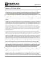
Chapter 5: ANT Radio System
No matter how many times you listen to a song on a radio, talk on your cell phone, or check your
location on your GPS, you have to appreciate the fact that massive amounts of information are whizzing
around you, and somehow, someway, the device in your hand can pick out the signal you want from
everything else and show you meaningful data. The radio frequency (RF) world of wireless data transfer
is truly amazing, and is becoming more and more accessible to incorporate into embedded systems.
Though there will always be an element of “black magic” in any RF design, the global knowledge and
experience base and sheer number of companies and individuals who can wield that magic is growing
every day.
To penetrate the market with a radio system that will be widely adopted is a sizeable task. The system
must be viable in every way: usability, function, performance, cost, accessibility and popularity. All of
these characteristics are almost exactly orthogonal to each other at the beginning – essentially a Catch22-22-22! How many wireless technologies do you know? AM/ FM radio, Wi-Fi, Bluetooth, CDMA,
TDMA, GSM, UMTS, HSPA may all be in your repertoire. Of these, only Bluetooth is suitable for smaller,
personal networks, but the protocol is complicated, the overhead is sizeable, and the actual number of
real applications – though theoretically quite sizeable – has been limited to cell phone head sets and
wireless music players.
Consumer and commercial markets have started to see growing demand for personal area networks
(PANs) that are ultra-low power, easily deployable, highly interactive and low in cost. A PAN is intended
to service individuals within a limited sphere of coverage - perhaps 30 feet or so - with the intent of
seamlessly interacting with the user’s immediate environment so their surroundings can be customized
when they are present. In many applications, data rates have become less of a concern as devices are
looking for more passive interaction and can make things happen with sometimes as little as only a few
bytes of data exchanged. For example, your front door can unlock as you approach it if you carry a key
fob in your pocket. The same key fob can unlock your car doors and disarm your security system, sign
you in to work, and identify you at the local coffee shop all by transmitting just a few bytes of data.
The PAN concept is gaining momentum as more and more applications for wireless technology emerge
and the capability to integrate that technology grows. A leading example is in the fitness world, where
users are demanding smarter interfaces to exercise equipment as well as feeding a growing obsession
with data monitoring and collection. There is also a growing interest from a social networking
perspective that is already serviced over long distances through cellular technology, mid-range distances
with Wi-Fi, but is still looking for a standard solution for the short-range leg. The race is on to offer a
solution that will be adopted by the world.
Bluetooth is trying to adapt to meet the growing needs of the PAN and has developed a standard called
Bluetooth Low Energy (BLE) that somewhat hits the mark. The Zigbee consortium has been running
since the early 2000s and has achieved reasonable market adoption and penetration amongst engineers
notes_mpgl2_chapter5.docx
Release 1.0
Page 1 of 29
MPG LEVEL 2
but not so much in the consumer space. Zigbee radios sit on the fringe of the PAN and the wider-area
network, offering a solution that works but is not ideal.
Dynastream’s ANT protocol coupled with Nordic Semiconductor’s low power 2.4GHz radios have
emerged in the last few years and offer an excellent solution to meet PAN needs. The ANT Alliance is
growing at a remarkable pace, and companies are finding ways to use the technology in an increasing
number of applications and devices that further spurs demand. ANT meets all the needs of the PAN and
continues to develop in popularity and application. This course has already introduced the hardware of
the 2.4 GHz ANT radio and now is the time to put it to the test to see why it is the premiere up and
coming wireless technology in the world.
This chapter takes an in-depth look at the ANT protocol as it is presented from Dynastream, then
examines the drivers and application code that will be used to establish and maintain the radio link for
the Pong application using ANT. The main purpose is to guide you through the driver code that has been
written already to help you become more fluent with ANT. In the chapter exercise, you will use the
code and work with the JLink and UART debugging tools to get a solid feel for how the system works.
This is a critical step before moving on to building the Pong application as it will be imperative that you
know how to debug your system as you write code.
5.0 ANT Wireless Radio
Dynastream introduced the ANT protocol only a few years ago as a candidate to address the growing
need for PANs and has made great progress in the cycling world with 100% user adoption in some cases.
ANT is rapidly gaining market share in other fitness and health-related applications as people
understand its capabilities and more applications adopt and support it. ANT competes with the IEEE
802.15.4 standard on which “Zigbee” is based and will soon be competing with Bluetooth Low Energy
(BLE) if BLE can ever get off the ground. Each technology has advantages, but ANT is the clear winner in
power consumption, ease of implementation and cost, and was thus selected for this course as it
perfectly meets our needs.
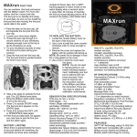
Communicating with the ANT protocol is quite simple. On the hardware side, the development board
contains everything necessary to implement the transceiver including the latest AP2 ANT chip and a PCB
antenna. This hardware can achieve line-of-site range up to 100 feet, though for very reliable
connection a range of up to 30 feet is more appropriately specified. The work we will do to implement
ANT is the development of the host system that will interact with the ANT protocol stored on the AP2.
Following the ANT design guidelines and documentation, we will build a state machine-based system to
send and receive ANT messages that carry the data to synchronize our systems. On top of those drivers,
we will design a custom application that will allow us to pair to another device and exchange messages
to achieve the game play we want.
notes_mpgl2_chapter5.docx
Release 1.0
Page 2 of 29
MPG LEVEL 2
All ANT documentation can be found in the Developer zone on the Dynastream ANT website:
www.thisisant.com. The main documents that any ANT developer needs are:
1. ANT Message Protocol and Usage
2. Interfacing with ANT General Purpose Chipsets and Modules
3. nRF24AP2-8ch, -1ch Product Specification
It is from these documents that all of the implementation of ANT hardware and firmware in this course
are based. The course also makes use of some of the example code available to ANT developers to
ensure the firmware presented here is consistent with Dynastream’s design fundamentals. Though our
drivers will be slightly different due to hardware and specific requirements, the general ideas of
implementation layers, suggested state machines and naming conventions are followed closely.
Understanding ANT in this course will provide a solid foundation on which your own ANT-based
products can be based.
5.1
Getting Started With ANT
When starting to use any new piece of hardware, the first thing you should do is a lot of reading to try to
understand the new technology from the manufacturer’s perspective since they are the experts at it.
Data sheets and application notes should be gathered and organized, making sure you have the latest
revisions and all of the information. This material should be kept in an easily accessible location as you
will no doubt be referencing it frequently as you are first integrating the device. This chapter will not
repeat all of the information that is already published on ANT, but it will reference a few of the most
important pages and reiterate or expand on key concepts.
Before reading this chapter further, you should take some time to download and review three key
documents from the ANT website, www.thisisant.com. Navigate to the Downloads page and you should
see the documents near the top:
1. ANT Message Protocol and Usage
2. Interfacing with ANT General Purpose Chipsets and Modules
3. nRF24AP2-8ch, -1ch Product Specification
There are also links to these documents on the course Links webpage. Note that the Interface
document has already been looked at in Chapter 3 to assist in configuration the SPI module.
Just like you have a bible for this course, the ANT Message Protocol and Usage guide and the Interface
document make up the bible for ANT and should definitely be read. It is recommended that you read
through the entire document before continuing so that you get into the context of the rest of the
discussion. We have already referenced the Interface doc to set up the hardware, but it contains
additional information about the signaling required to send and receive ANT messages and is thus
notes_mpgl2_chapter5.docx
Release 1.0
Page 3 of 29
MPG LEVEL 2
essential to reference while writing code in this chapter. The AP2 product spec is just for your reference
and is not essential to read right now since your hardware is already designed.
It is handy to have a hard copy of the ANT documentation you will use the most. You do not need to
print it all, but it is highly recommended to print the ANT Message Summary table and the Channel
Response Message Codes (pages 40, 41, 42, 73, 74 in rev 4.1 of the protocol document) and add them to
the course bible. You will reference these pages a countless number of times as you develop with ANT.
5.2 ANT Message Protocol and Usage
The ANT Message Protocol and Usage document is the key specification for implementing ANT. It
covers everything from how different networks can be formed, to the exact bytes that will be exchanged
as messages between your host controller and an ANT device. Since it covers absolutely everything
about the ANT protocol, some of the information will not apply directly to how ANT will be used here in
the course, but it is a good idea to review the material so you know the full capabilities of ANT.
5.2.1 ANT Protocol: Sections 1 thru 4
Sections 1 and 2 are a brief introduction to the ANT system and available hardware used to realize an
ANT-based PAN. Section 3 gives you a full overview of the network topologies that can be supported by
ANT – start dreaming of your applications! Section 4 clarifies some terminology and emphasizes that
any implementation of ANT requires a host controller along with the ANT engine for each “Node” in an
ANT network. At the very least, two nodes would be required to communicate. Each development
board with the LPC175x and AP2 hardware makes up one node of the intended two-node network.
To clarify some terminology, in most discussions of an ANT system at the application level, “Master” and
“Slave” refer to ANT nodes where communication takes place over the air. The devices on which
communication occurs within an ANT node are between the ANT device (the AP2 in our case) and the
host controller (the LPC175x) are simply denoted “ANT” and “Host.” A bit of confusion may arise since
within an ANT node, the SPI protocol used to implement that communication has a master-slave
relationship. That reference to master and slave is kept at the peripheral serial driver level as in Chapter
3. Here in Chapter 5, discussion of Master and Slave will always refer to ANT nodes.
5.2.2 ANT Protocol Section 5: Channel Parameters
Section 5 in the ANT Protocol document is very important as the core concepts of the ANT Master and
Slave relationship are described, along with the key channel parameters that come together to allow
two devices to communicate.
5.2.2.1 ANT Node Parameters and the Master-Slave Relationship
One of the important take-aways here is the list of configurable parameters available to define an ANT
node:
notes_mpgl2_chapter5.docx
Release 1.0
Page 4 of 29
MPG LEVEL 2
1.
2.
3.
4.
5.
Channel Type
RF Frequency
Channel ID
Channel Period
Network
Remember that communication between two ANT nodes takes place on two levels: the radio/ANT
interface and the ANT/Host interface. Before you have even a hope of getting two devices to talk to
each other over the air, they must communicate at the radio/ANT interface. For this to happen, at least
two ANT systems must be configured on the same RF Frequency and with Channel Types set such that
there is at least one transmitter and at least one receiver in the network. Setting the Channel Type is
how the Master and Slave devices are designated.
The device you assign as a Master might not be what you would initially expect. For example, if you had
an array of remote sensors that were communicating temperature readings every minute back to a base
station, which device would be the Master? The sensors are the Master in this scenario since they
initiate communication. The Master always initiates communication in the ANT protocol. In most ANT
deployments, the ANT Master is the low power device since it can start broadcasting when it needs to
and shut down and sleep when it is done. The receiver, on the other hand, must spend more time
actively listening for traffic so it will use more power to keep its receiver on so it does not miss any
messages. The whole Master/Slave relationship in the ANT world may seem counter-intuitive at first,
but as you start to explore your application you will see that it makes a lot of sense.
If you have the radio settings correct and a Master/Slave device pair is in close enough proximity to each
other, then messages will be exchanged between the two devices (as long as you have told each device
to open a channel). At this point, the proprietary operation of the ANT protocol kicks in. As a user of
these devices, you will probably never know exactly how two ANT devices synchronize and start
communicating with each other (though you can take some guesses). However, you do not need to
know the details as long as it works, and it happens to work very well even if you have multiple systems
in the same area.
This is where the other channel configuration parameters come in. Though the ANT/radio side of a
receiving ANT device will hear essentially any and every messages that are at the same frequency, it will
parse all the data it sees and pick out messages that match the channel parameters you have set. There
is a level of security that has something to do with the Network key set in the device – probably some
sort of encryption based on the Network key that will scramble the message data. For development
purposes, the Network key is always 0, referred to as the “Public Key” that is not protected. For specific
applications, network keys are assigned and certain networks have an associated set of rules that define
how devices in that network should behave. This is the basis of the ANT+ ecosystem and allows
interoperability between ANT devices from multiple vendors with multiple products. If you do not want
notes_mpgl2_chapter5.docx
Release 1.0
Page 5 of 29
MPG LEVEL 2
to play with others, you can purchase your own Private Network key from Dynastream to operate your
devices privately from any other ANT devices and therefore set your own rules.
The message period also comes in to play, which is the rate you define for messaging to occur. The
standard / recommended rate is 4 messages per second (4 Hz). Once you are actually working with ANT
it is unclear how exactly synchronization to the message period happens. It takes two devices about 2-3
seconds to “pair” when a 4Hz message period is in use, so there must be some sort of algorithm
operating to read incoming messages and decide when they are consistently available. If you have
access to an ANT development kit, you can observe the pairing process as you turn on a device, then in a
few seconds see data messages. A Slave device with 4Hz messaging period can pair with a Master with
2Hz messaging, though the Slave will report missed messages every second period. Again, the details of
the exact implementation of the ANT protocol are hidden but really do not matter. If you want two
devices to talk, the best way is to make sure all of their channel parameters match exactly and go to it.
5.2.2.2 ANT Channel ID
The other very important element described in Section 5 of ANT Message Protocol and Usage is that of
the Channel ID. Try not to get mixed up when talking about channel setup and channel parameters and
channel type and Channel ID. Channel ID is a specific group of parameters that ultimately determine
whether two ANT systems will talk. The Channel ID is made up of three fields:
1. Transmission Type (8-bits)
2. Device Type (8 bits: 7 bits for a device type, 1 bit for a “pairing bit” that will be discussed later)
3. Device Number (16 bits).
Once two devices are synchronized and messages are passing the security layer, ANT will check the
Channel ID and decide whether or not to pass on each message to the host controller. If the Channel ID
does not match the device settings, the message is simply discarded and as far as your system is
concerned, was never received. For a given network, it is likely that all devices belonging to that
network will have matching Transmission Type and Device Type. Therefore, the 16-bit Device Number
allows 65,535 unique devices.
For a Master device, all three fields must be set explicitly before the channel is opened. On the Slave
side, values that match the Master can be set, or any or all of the values can be set to “0” for a wildcard.
This allows you to control how your devices behave and pair up to communicate. If you know the exact
Channel ID of the nodes that need to talk, then you can set all three fields and be assured that the ANT
protocol will exchange messages only between the devices with matching Channel IDs. If you are not
sure about whom you want to communicate with, or if you purposely want to communicate with
multiple Masters, then you can make use of wildcards.
If you set wildcards on a Slave device and the Slave then pairs with a Master, the wildcard fields in the
Slave will be changed automatically to the Channel ID of the first Master device that communicates with
notes_mpgl2_chapter5.docx
Release 1.0
Page 6 of 29
MPG LEVEL 2
the Slave. The Channel ID will remain that way until the Master stops broadcasting and the Slave search
times out. If the Slave has not yet timed out and a new Master with a different Channel ID tries to
communicate, it will be ignored because the Slave will still be trying to communicate using the previous
Master’s Channel ID. The timeout period is a configurable parameter that can be set from a few
seconds to infinite. That setting needs to be considered for the system you deploy if you rely on the
timeout to occur before communicating to another device. If the Slave finds and pairs with a particular
Master, exchanges data and knows that it does not need any more data, then the Slave can close the
channel and reopen it with a new wildcard search.
5.2.2.3 Transmit Data Types
The type of Data that is exchanged between two ANT nodes falls into one of three categories:
1. Broadcast Data: one-way fire and forget messaged.
2. Acknowledged Data: receiver responds to confirm that the message was received. It is up to the
host software to resend the message if an ACK is not received.
3. Burst Data: large amounts of data sent as acknowledged data messages. ANT automatically
retries any messages within the packet that are not ACKed. The host receives confirmation of
success or failure for the complete packet of data.
Both Master and Slave can send any of the data types. Broadcast and Acknowledged data messages
always have 8 bytes of payload data that is sent. The Master sends data first at the set message rate,
and the Slave will respond with data immediately following the end of the Master’s data if a message
has been queued up.
When a channel is open on the Master, data is always sent from the Master at the defined message
period to maintain the channel synchronization. That means that regardless of whether or not you have
meaningful data to transmit, the ANT protocol demands that data is sent. If you do not give the Master
new data to send, it will simply repeat sending whatever the last data packet was. Given this
information, you must ensure that your Slave device will properly handle the continuous message
stream regardless of whether or not the message data is stale or fresh.
There are a lot of ways to manage this, and the rules that you establish for your system will likely differ
from others. Your system may be able to handle the repeated data without any problems. For example,
if you had a sensor network where a Master was sending the current temperature as data, then as long
as the continuous messages had the latest temperature reading the system would function well. If the
system could not handle repeated data, your application could define its own application protocol such
that the data sent contained some sort of flag byte, message number, or enumeration byte that could
be compared by the Slave to the last message received to determine if the message is new – all that
would happen in your application because ANT relays anything it receives to the host .
As far as the three transmit data types go, broadcast messages are the default type and those are what
the system will send at the message period if you do not instruct it otherwise. Since broadcast
notes_mpgl2_chapter5.docx
Release 1.0
Page 7 of 29
MPG LEVEL 2
messages do not get acknowledged by the Slave, the Master has no way of knowing if any Slave received
the message. Broadcast messages are good because the Slave does not have to use power to send an
acknowledgement back, and the Master does not have to have firmware to deal with it.
To send a broadcast message, you build message 0x4e with 8 bytes of payload data. If you have less
than 8 bytes of data to send, then you can add dummy bytes into the unused payload byte locations.
Clearly, the receiver that is getting the message must know how to deal with the data packet. Once you
send the broadcast data message to ANT, you will get a Channel Event message back telling you that the
message was sent okay or Channel Response with an error code if something went wrong (an unopened
channel is the most likely error). Remember that a Channel Event message and Channel Response
message are both Msg ID 0x40 but with different parameters. Assuming the message was sent
successfully, the response message is the cue to your system that the next broadcast message can be
provided to ANT. If your system does not provide a new broadcast message to ANT, it will still receive a
ChannelEvent message every message period because the system always sends broadcast messages to
maintain the channel.
An acknowledge data message (0x4f) works exactly the same as a broadcast message up to the point
where you get a response back from ANT. Instead of a Channel Event that simply tells you the message
was sent, the Channel Event will have a code that indicates either the message was sent and
acknowledged, or the message was sent but not acknowledged. If the message fails, it is not
automatically retried. The Host can decide to resend the message or send a new message – in either
case the Channel Event is again used to cue the next action. If the host does not queue a new message,
the next message ANT sends will be a broadcast data message to maintain the channel. Using an
acknowledge data message is essential in a system where data reception is critical. It is also a good way
for a Master to decide if it can stop transmitting because the data that it is trying to pass has been
received successfully. That being said, the Slave that sends the Ack back to the Master does not know
that the Ack was received by the Master.
Burst data messages allow very fast data transfer to occur over the ANT channel. Data rates up to
20kbits/second can be achieved. ANT message and protocol usage describes the gist of burst transfers,
but there is also an application note that further explains it. Since this course will not use burst
transfers, no further discussion will occur here.
The remainder of section 5 in the ANT protocol document talks about some other interesting features of
ANT. Since the course will not make any use of these, no attention will be given to them in this chapter
but the reader is highly encourage to read and understand these capabilities as their applicability is very
high for other ANT usage scenarios.
5.2.3 ANT Protocol Section 6: Pairing
Section 6 talks about the concept of pairing a Master and Slave ANT node and the different pairing
relationships you can plan for. Again, the important detail to remember is that in order for two ANT
notes_mpgl2_chapter5.docx
Release 1.0
Page 8 of 29
MPG LEVEL 2
nodes to communicate, their Channel IDs must match. A Master’s Channel ID must be completely set
and in some way unique to any other Master, but a Slave Channel ID can have wildcard parameters that
will allow it to search for Masters within a group based on the different parameters of the Channel ID.
For the course system, the Transmission Type and Device Type in the Channel ID will be fixed but the
Device ID will be settable by the user. Since pairing of two devices will be user-initiated, the pairing bit
will be used to help eliminate any incorrect pairings when more than two devices are present. For
example, if two ANT nodes are paired and engaged in some major Pong action and two players nearby
decide to start their own match, then there is a high chance that the Slave device in the new set of
devices could pair with the Master of the original set of devices. Note that the act of pairing here means
that the Slave is searching for a wild card device ID and when it finds a Master it will adopt its device ID
and stop looking at any others. So if the signal from the Master that is already paired happens to find
the new slave first, then that Master will be paired with two slaves and the system will break (although
it could be sort of interesting…). If the pairing bit is used, then this type of conflict can be avoided since
the pairing bit is another unique part of the Channel ID though only used during the initial pairing
operation. That being said, pairing errors could still occur if two sets of devices were trying to pair at
exactly the same time with matching channel parameters.
There are some further notes on pairing in Section 6 of the protocol document that are worth reading,
especially the information on Proximity Pairing that helps to further mitigate the problem of incorrect
pairing relationships forming. This is a new feature found on only the latest ANT devices, and is an
excellent example of how Dynastream is continuously improving their technology in response to realworld feedback.
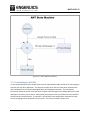
5.2.4 ANT Protocol Section 7: ANT Message Structure
We have talked a lot about the messages that are exchanged in the ANT protocol but have not yet
looked at the actual frame used by ANT. Section 7 in the Protocol document fully explains how
messages are put together, but we will emphasize the most important parts here.
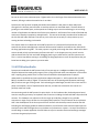
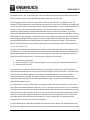
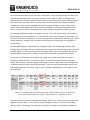
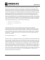
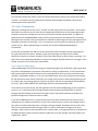
All ANT messages follow the same format shown in Figure 5.2.4.1 taken directly from the protocol
document.
Figure 5.2.4.1: The ANT message Frame
Source: ANT message protocol and usage 4.1.pdf, Dynastream Innovations Inc.
notes_mpgl2_chapter5.docx
Release 1.0
Page 9 of 29
MPG LEVEL 2
For asynchronous transmission the Sync byte is always 0xa5. For synchronous transmission (like in the
course development board) the sync byte is 0xa4 for a write or 0xa5 for a read. A message parser
should throw away any frame that does not start with the correct sync byte and keep looking through a
data buffer until a Sync byte is found. The ANT device should never pass an improperly formatted
message to the host, so the only probable cause of an incorrect message is an error in the SPI data
transfer and/or associated driver functions that are responsible for receiving message from the ANT
device. If ever the host finds a bad message, the system should be checked very carefully for bugs.
The Message Length (Msg Length in the diagram and just “Len” in the protocol spec) is the number of
payload bytes in the message where N is a maximum of 9 in most cases, though it can be as high as 13
for special “extended” message types. Since this byte appears immediately after the Sync byte, it can be
used to condition a message parser to read the remaining bytes in the message since messages are
variable length.
The Message ID (Msg ID) corresponds to the message number in the ANT Message Summary table.
Probably every ANT system will have a header file with mnemonics for these along with their associated
message lengths. This field is the key byte of information used to process the messages received and
will generally be the parameter in a big switch statement that handles all the different messages.
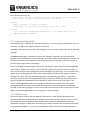
The content of the data bytes varies with each message, so be careful that you do not make any
assumptions about the values. In most cases, Data 1 is the channel number to which the message
applies, but not always. The other slightly confusing part is that the “Data” bytes in the message frame
are different than the “Data” bytes of data messages. If you look at the Data Messages section of the
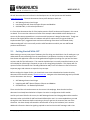
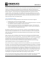
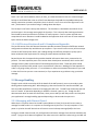
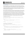
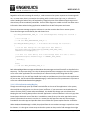
ANT message table, you will see this. Figure 5.2.4.2 is a slightly modified version of the table to show
this specifically.
Figure 5.2.4.2: Modified clipping from the ANT Message Summary table showing the message bytes
Source: ANT message protocol and usage 4.1.pdf, Dynastream Inc., modified for example
The Protocol document calls the message payload bytes “Data 1” thru “Data 9”, but the message frame
diagrams call them “Data_1” thru “Data_N” (a slight naming mis-match). This number and naming
refers to bytes in all messages. The actual data bytes in data messages are referenced as Data0 thru
notes_mpgl2_chapter5.docx
Release 1.0
Page 10 of 29
MPG LEVEL 2
Data7. So if you read it verbatim, Data 2 (or Data_2) is Data0 and Data2 is Data 4 in a data message!
Perhaps it would have been nicer to call the frame data bytes Payload0 thru PayloadN and keep the
naming convention consistent everywhere, but it is what it is and it is not so hard to figure out in the
end – just be aware if you are discussing or reading about data bytes.
The last byte in the frame is always the checksum. The checksum is calculated as the XOR of all the
previous bytes in the message starting with the Sync byte. This is the only data checking mechanism
that the ANT protocol provides but is sufficient for most purposes. If ever a system required more
comprehensive error detection it could be added at the application level at the cost of some overhead
bytes used in the data messages sent.
5.2.4 ANT Protocol Sections 8 and 9: Examples and Appendix
The last full section of the ANT Protocol document provides numerous examples of different network
configurations and how they would be set up to operate. If you are still unclear on any of the concepts
of how an ANT-based system works, then reading through the different examples may help you to
better understand the requirements for setting up various Master and Slave nodes.
Beyond Section 8 is the Appendix that provides detailed information about every command in the
protocol. The most important parts of this section have already been mentioned, which are the ANT
message summary table and the table of Channel Response/Event codes. These two tables should
already be printed and safely stored in your course bible for reference. Reading all of the Appendix in
order is not going to help you much – it is much better to reference command information as you need
it either the first time you use a new command, or if you experience any problems using a particular
message.
5.3 Message Handling
Though it took a while to articulate all of the details of the ANT protocol, you are now ready to start
thinking about implementing ANT. When designing a host state machine to interface with ANT, you
have to handle the different scenarios of messaging that will occur. The ANT-Host relationship has two
sorts of “modes” of operation depending on whether a channel is open or not. Though the ANT
documentation does not make this distinction, when you use ANT you will likely notice it and may alter
your application’s message handling approach depending on what mode the system is in.
5.3.1 Messaging with Channel Closed
When there is no active channel in the ANT system (Master or Slave), the host will never receive a
message from ANT unless it is a response to a message sent by the host. The only exception is if the
power is cycled on the ANT device that will cause it to send a Startup message (0x6f) to the host.
During this closed-channel mode, only Configuration and Control messages from the host should be sent
to ANT. Trying to send a data message does not make sense as the data has nowhere to go and ANT will
notes_mpgl2_chapter5.docx
Release 1.0
Page 11 of 29
MPG LEVEL 2
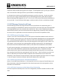
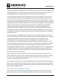
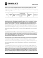
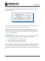
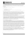
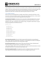
not like this (it will respond with an error message). When a configuration message is sent, a single
response will be received from ANT in reply to that message to indicate whether or not the
configuration message is accepted. This reply comes in the form of a Channel Response message (0x40)
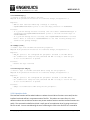
as shown in Figure 5.3.1.1.
Figure 5.3.1.1: Format of the Channel Response message
As already eluded to, message 0x40 is a bit confusing because it doubles as a Channel Response and
Channel Event message. While the Channel Response is typically a reply to a message sent, a Channel
Event is more of an unsolicited message from ANT to the host when there is a channel active (more
discussion in the next section). In either case, message 0x40 contains a Response Code that must be
referenced against a different table in the document (see Message Codes on page 71 of the ANT
protocol document v4.1). The table combines response codes that can come when the system is idle
and thus when Channel Response is a reply to a command you are issuing, but also contains the codes
for when the message is a Channel Event. It is handy to have this page printed in your course material
as well.
As a Channel Response message, the response code will either be 0 meaning the message was
successfully sent, or will be an error code that provides a reason why the command was not acceptable.
Since not every possible reason for a failed message can have a distinct error code, you may have to do
a bit of digging to understand the error source. In any case, your system must parse a few bytes of the
message to handle it appropriately and decide how to react.
Generally speaking, a Channel Response message should be used to ensure that the channel setup you
want based on the configuration messages you send is successfully set up. If any Channel Response
indicates that your command is not accepted, your system must react and either retry, change
parameters, or reset the ANT system. In general, communicating to ANT when the channel is not open
will involve messages that are critical to the setup and your system should not proceed if any of the
messages fail.
If a message does fail for some reason, it is unlikely that retrying the same message is going to work
because if it was formatted correctly enough to get a response from ANT but ANT tells you it does not
like the message parameters. The brute-force approach of resetting the ANT device after a message is
denied works when the message you are trying to send normally works but for whatever reason is not
currently working. You could try to send different messages to ANT to see if you can correct its state
(like try to reconfigure other channel parameters that may be the cause of the conflict of what you are
currently trying to configure), but that can lead to some fairly complex code to try and implement.
notes_mpgl2_chapter5.docx
Release 1.0
Page 12 of 29
MPG LEVEL 2
Most likely you will find that bad responses to configuration messages result from programming errors
and will be up to you to fix long before the device ever leaves your work bench. If you cannot figure out
why a message fails just by reading the ANT documentation, the best way to solve the problem is with a
breakpoint, debugger, and watch window showing the received message from ANT so you can manually
figure out what is wrong and make the correction. The key here is the Response Code that is returned in
the Channel Response message. If the Response Code is anything but 0 (no error), then take note and
figure out how to make the correction.
Beyond simply getting the parameters of a message wrong, probably the most common error comes
from trying to do something on a device that is not supported by the ANT part you have in your system.
For example, the course development board uses a single-channel AP2 ANT device. If you try to
configure or open any channel other than channel 0, the device will tell you that your message has
incorrect parameters.
All of the Configuration messages will receive a reply from ANT, so your system is usually set up to send
a message and wait for a good response before proceeding. If the configuration stream you send has
been verified to work properly, then you can be reasonably assured that it will always work when it
runs. If the system gets into a state where something that normally works no longer works, a system
reset is often the best approach to getting around the problem. If the error happens consistently, then
the application should be examined to find the root cause of the failure.
If you try to send Configuration Messages for a channel when the channel is open, they will fail because
channel parameters cannot be updated on the fly. If you try to send data messages when the channel is
closed, you will in fact get a response from ANT even though the ANT protocol document indicates there
is no reply to these messages. The response is a Channel Response message and the Response Code will
tell you that the channel is not in the correct state to receive data.
5.3.2 Messages When Channel is Open
The messaging that takes place when a channel is open is quite different on a Master compared to a
Slave. If the system is left idle with the channel open, the Master ANT device will continually send the
host Channel Event messages indicating that Broadcast messages have been sent every message period.
Whenever one of these messages is received by the host, it can use the signal as an indicator to queue
new data for the next Broadcast or Acknowledged data message. As long as the Host can prepare the
data and send the data message to ANT in less time than a message period, new data can be sent with
each message. If the host is too slow or does not have new data to send, ANT will still send the same
Broadcast Data as it did on the last transmission and continue to send the Host Channel Event messages
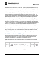
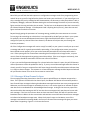
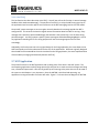
to indicate the Broadcast message event. When the channel is open on the Master, most of the
messages received will be message 0x40 in the form of a Channel Event message that gives you status
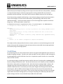
about what is happening. Figure 5.3.2.1 shows the format.
notes_mpgl2_chapter5.docx
Release 1.0
Page 13 of 29
MPG LEVEL 2
Figure 5.3.2.1: Message 0x40 as a Channel Event
On the Slave side of the system, the receiver is active and waiting to get messages from a Master. If no
Master (with matching channel ID) is present, then the Slave ANT will not be sending any messages to its
host. If no messages are received within the timeout period setup for the system, then ANT will
automatically close the channel and indicate the timeout with a message to the host. However, if a
Master is present and the devices have paired, then the Slave should be getting Broadcast or
Acknowledged data messages (whichever are being sent) at the system message rate (in our example
this is 4 Hz). These messages will come through as message 0x4e (Broadcast Data) or 0x4f
(Acknowledged Data). Even if a message is missed, the Slave will still communicate to the Host on the
message period but will simply tell the host that an expected message was missed. It will do this for at
least 8 consecutive missed messages. If a message from the Master is received, then the missed
message count is reset. If too many messages are missed, the Slave will automatically close the channel
and tell the host that it has given up.
5.4 Debugging an ANT System
Seeing how a system operates is by far the best way to start fully understanding it. If you have an ANT
development kit, you can configure your own Master device, open a channel, and see the messages
received through the development kit software running on a PC. Alternatively, you can configure the
dev kit to be Master and run your own Slave device to see how it behaves. The development kit offers
easy setup of the Master to help you control the system to ensure everything is working properly. The
only problem is that the kit is quiet expensive for a hobbyist or student budget.
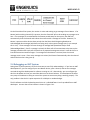
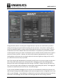
The PC software to which the development kit ties in is called ANTware II and is provided free to ANT
developers. A screen shot of the interface is shown in Figure 5.4.1.
notes_mpgl2_chapter5.docx
Release 1.0
Page 14 of 29
MPG LEVEL 2
Figure 5.4.1: Screen shot of ANTware II from Dynastream Innovations
Though the ANT protocol is actually quite straight forward, if you have not used it before you will be
surfing the learning curve just like with everything else new you learn. A key factor in working with a
whole new module like ANT is having a known working device that you can use to get going. Trying to
troubleshoot brand new hardware with brand new firmware is very difficult as you never know what
variable might be causing you trouble. Development kits are available for ANT products and are great if
you have no other resources. However, the course ANT hardware implementation is also a proven,
working design and the steps use to program and test the device will guide you along until you can fly
(or crawl in the case of an ant) on your own.
Even if you have an ANT development kit, eventually you will have to run just your system to make sure
both of your ANT nodes properly pair and communicate. Debugging can be more challenging here
because of the number of messages that will be coming in from ANT. Though 4 Hz may not seem very
fast, if you are trying to read 4 messages per second it gets overwhelming very quickly. Even logging 30
seconds of communications will result in over a hundred messages.
If you are using a hardware debugger for your host you can set breakpoints and halt the processor, but
ANT will keep running and sending messages at the system message rate that is configured since it is not
tied in to your debugger. If your hardware is configured in synchronous mode and is halted so it will not
allow ANT to send messages, ANT will buffer a few messages and then start sending “lost data”
notes_mpgl2_chapter5.docx
Release 1.0
Page 15 of 29
MPG LEVEL 2
messages which can sometimes upset debugging even further with an added message type. A good
method for debugging is to have a fairly large receive buffer so that you can capture enough of a
representation of the messages being received so you can find out where your problems are. Even if
you have to borrow some RAM from other applications during this test process, it is a good way to see
what your system is getting from ANT.
Another excellent tool is to have a serial output of the messages that ANT receives. UART debug access
ports are very common in embedded systems because they are very simple to setup as long as you have
the hardware in place on your development board. Naturally, the course development board comes
equipped with a UART connection. As we develop the ANT data handler, we will develop a debug mode
that will be used to further support learning and debugging efforts with ANT. Even though you will have
the full source code for the course application, if you want to explore the code further or build different
ANT-based systems using the course development board, the debug output will be a very handy tool.
5.5 Programming the ANT Sub-System
With all this information in your hands, you should hopefully have a good idea about what ANT can do
and, in general, how to do it. No doubt you need to try using ANT before you will fully understand
everything. Even then you will continually be reviewing the documentation and coming up with little
problems that need to be solved. At least now we can begin talking about the ANT sub-system that will
make use of the protocol to provide radio functionality to the Pong system.
If you were designing this system from scratch, you would want to sit down and carefully consider all of
the details that will have to come together to make it work. At this point, not too many specifics of the
Pong application have to be known, but we need to ensure that our core ANT driver provides all the
functionality and services needed by the application and ensure that it will run reliably. Since we
already have the basic SPI drivers written, programming the ANT sub-system will focus on setting the
hard-coded parameters of the system, taking care of initialization of the ANT device based on those
parameters, and implementing a message sending and receiving mechanism that allows configuration
and communication to take place. All the code will be kept in the source files ant.c and ant.h.
For the course’s implementation of ANT, power consumption is not really going to be a concern since
the course development board plugs in (or we have a pretty big battery) and we have a user-initiated
pairing process. Once a connection is made, we want it to remain active, so both the Master and Slave
will be consuming essentially the same amount of power while the game is active. If the devices get
separated, the Slave device may draw more power if it continues to try to look for a Master.
5.5.1 System Parameters
The course development board needs to implement ANT to exchange messages between two ANT
nodes that will be the two game nodes in the Pong application. Since this is a non-production device,
we can develop using the ANT public network key (all 0s). As mentioned previously, our ANT devices will
notes_mpgl2_chapter5.docx
Release 1.0
Page 16 of 29
MPG LEVEL 2
have a Channel ID with a fixed Device Type and Transmission Type, but each unit will have a unique
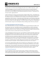
Device ID (though by default the Device ID will start at the same number). Figure 5.5.1.1 shows a
graphic of the Channel ID.
Figure 5.5.1.1: Channel ID for the course development board ANT devices
These values will be pre-processor definitions in our ANT header file. This header file will grow as the
application is built with other constants and functions headers as required.
The radio frequency can be chosen arbitrarily for now and will be selected as 55 for no reason in
particular, other than it is close to the middle of the entire 2.4GHz frequency band so we are not in
danger of radiating outside the allowed band. For best communication capability, the device power
level will be set to maximum (0 dBm).
5.5.2 ANT Firmware
Referencing the ANT application examples is a good idea now, too. The User Manual provided with the
reference design describes the programming approach where three layers are identified:
1. Serial Drivers (BitSyncSerial.c and associated header files)
2. Interface (ANTInterface.c and associated header files)
3. Application (coded as various example main programs)
Looking at the services provided by each of the functions gives a good understanding of how the layers
interact. The abstraction used is solid and breaks the necessary functionality down nicely. The serial
drivers are as generic as possible so that any application can use them. The interface layer has the
functions that can be used by the application to use ANT without any knowledge of the operations going
on.
notes_mpgl2_chapter5.docx
Release 1.0
Page 17 of 29
MPG LEVEL 2
ANT firmware for the course development board will follow the example code structure provided by
Dynastream very closely to ensure that our system design is consistent with recommended practices.
Where possible, the same or similar function names will be used and the type of functionality provided
with our functions will be close to that of the example code. Not only does this help by having a road
map, but it also could help later on should any problems arise where Dynastream support is contacted.
If the implementation here is close to the example code, it will be much easier for both parties to
understand what is going on and what may be wrong. If you have ever tried reading someone else’s
code you will know how difficult it is to quickly understand everything in their design – that includes this
course! Understanding just the design is one thing, understanding the code that makes up that design is
a whole other thing. If you can eliminate one of those by following a reference design, then obtaining
support becomes substantially easier. The files we will be referring to are:
•
•
•
•
antdefines.h and antmessage.h
BitSyncSerial.c and BitSyncSerial.h
ANTInterface.c and ANTInterface.h
Main_Demo1.c
Pre-processor definitions for all of the message numbers and other parameters used when
implementing the protocol are handy to make code readable. Dynastream provides developers with
such header files so we will include these verbatim: antdefines.h, antmessage.h. Note that these files
cannot be modified or make up part of a distribution without consent from Dynastream as indicated in
their disclaimer. The definition in the file for the two parameters that each message type requires is
shown here as an example.
#define MESG_BROADCAST_DATA_ID
#define MESG_DATA_SIZE
((UCHAR)0x4E)
((UCHAR)9)
With that in mind, now is a good time to mention a major consideration to be careful about when using
a reference design. Copyright restrictions must be considered if you take code verbatim or even if your
design is only loosely based on someone else’s. At the very least, you must ensure that you give proper
credit to the original author, and leave any disclaimer or copyright intact. If you are building a product
based on a reference design, it is a good idea to check with the original designer to see if they restrict
use of their intellectual property for commercial applications. In some cases, that is exactly the purpose
of the reference design. In other cases you may need written authorization from the original author.
And in certain cases, you may be completely and illegally infringing on their copyright and thus breaking
the law by using their design. When in doubt, ask. This is something where “it is better to ask for
forgiveness than permission” does NOT apply.
notes_mpgl2_chapter5.docx
Release 1.0
Page 18 of 29
MPG LEVEL 2
5.5.2.1 Serial Drivers
The ANT reference design uses a “bit-bashed” SPI driver instead of an SPI peripheral, so it does a bit
more work that what our system will require (see BitSyncSerial.c). Functions are provided to initialize
the necessary GPIOs and perform the correct Synchronous reset sequence. BitSyncSerial.c also provides
a single public function BitSyncSerial_Transaction(…) that takes care of sending and receiving ANT
messages with the help of some simple private functions ReadByte() and WriteByte(). Our Serial Driver
class must implement this same functionality.
Chapter 3 already covered the details of setting up and using the SPI peripheral on the processor and
this is invoked with a call to ANTSetup() during startup. Though the SPI peripheral is already configured,
we still need to properly start up and initialize the ANT interface and will therefore define our own
ANTSyncSerialIntialize() function to run the required start-up sequence. The combined send/receive
function of BitSyncSerial_Transaction(…) will be broken up into two separate functions AntTxMessage()
and AntRxMessage() to better integrate to our state machine application design. However, we will use
similar ReadByte() and WriteByte() functions, though of course ours will make use of the SPI peripheral
and integrate the ANT hardware flow control. The function headers for each are shown here.
u8 AntSyncSerialInitialize();
/* Performs the required signaling to ensure the SPI serial connection to ANT is
properly initialized. Sends a test message to retrieve the ANT version to verify
that communication is correct.
Requires:
- ANT is powered on and hardware configured for synchronous data
- Host SPI peripheral initialized as slave
Promises:
- Returns 0 if initialization is good or 1 if initialization fails.
*/
u8 AntTxMessage(u8 *pu8AntTxMessage);
/* Send a message from the Host to the ANT device.
Adapted from Dynastream Innovations Inc reference design, BitSyncSerial.c.
Requires:
- pu8AntTxMessage points to an ANT formatted message where the first data byte
is the length byte (since we get the SYNC byte from ANT) and the last byte is
the last data byte (since we calculate the checksum on the fly)
Promises:
- Returns 0 if the message transmits successfully
- Returns 1 if the message fails (timeout, receive message interrupted)
- SMSGRDY is de-asserted
*/
notes_mpgl2_chapter5.docx
Release 1.0
Page 19 of 29
MPG LEVEL 2
void AntRxMessage();
/* Receive a message from ANT to the Host.
Adapted from Dynastream Innovations Inc reference design, BitSyncSerial.c.
Requires:
- SEN has been asserted indicating a message is incoming
- LGpu8AntRxBufferNextChar points to the next empty character in AntRxBuffer
Promises:
- If a good new message has been received, then the counter LGu8AntNewMessages is
incremented and LGpu8AntRxBufferNextChar points to the next available byte in
LGau8AntRxBuffer.
- If a good new message was not received, then LGpu8AntRxBufferNextChar is moved
back to where it started in LGau8AntRxBuffer so the next incoming message will
overwrite the garbage message.
*/
u8 ReadByte(void);
/* Reads a byte from the ANT-connected SPI peripheral.
Adapted from Dynastream Innovations Inc reference design, BitSyncSerial.c.
Requires:
- ANT_SPI points to the configured SPI peripheral attached to the ANT device
- All communication setup has been performed and ANT is ready to send the byte
as soon as the SRDY bit is pulsed.
Promises:
- Returns the byte received.
*/
void WriteByte(u8 u8Byte);
/* Writes a byte to the ANT-connected device using the SPI peripheral.
Adapted from Dynastream Innovations Inc reference design, BitSyncSerial.c.
Requires:
- ANT_SPI points to the configured SPI peripheral attached to the ANT device
- All communication setup has been performed and ANT is ready to receive the byte
as soon as the SRDY bit is pulsed.
Promises:
- u8Byte is transmitted to ANT using the SPI peripheral.
*/
5.5.2.2 Interface Code
The interface functions will be coded inside ant.c where the serial driver functions are as well, but the
interface level code will be in a separate section of the file. This makes ant.c more like a C++ class
definition where the serial driver functions are private member functions and the interface functions are
public. The state machine definition (which is really part of our application layer) is going to end up in
this file as well. You can start debating the act of combining this code in the same file as it somewhat
notes_mpgl2_chapter5.docx
Release 1.0
Page 20 of 29
MPG LEVEL 2
defeats the purpose of explicitly calling out three layers of services and limits code portability. However,
in reality this whole design is inherently target-specific so having individual files in the name of
portability could be contested. At any time, the file sections could be broken out if it was desired.
Of the functionality provided in ANTInterface.c in the reference design, the only function that needs a
version to be brought in for the course is ANTInterface_ChannelConfig (), which will be called
ANTChannelConfig(). This function takes a pointer to a list of messages that is specific to the device
being set up. The function header is shown here:
u8 ANTChannelConfig(u16 *appu8ChannelConfig, u8 *pu8ConfigSize, u8 u8NumChannels)
/* Configures the channel parameters for an ANT device.
Requires:
- appu8ChannelConfig points to an array of pointers to the config command block for
each channel
- pu8ConfigSize points to an array of u8s that indicate the size of each of the
config command blocks
- u8NumChannels - the number of channels (config command blocks) appu8ChannelConfig
contains
Promises:
- Returns 0 if all channel configuration completes successfully
*/
The sample interface code provides a function to return a pointer to a received message, but our ANT
system will process ANT messages privately and communicate received ANT data through applicationlevel accesses, flags and message queues.
5.6 ANT Data
For transmitting data, the course code structure relies on the generic MessageSender state machine to
handle all outgoing messages. Therefore, we need to provide a function to queue an ANT message into
the MessageSender transmit buffer but since this is an application-specific interface it is not provided
within our ANT interface.
For receiving messages, the ANT state machine itself will take care of invoking calls to AntRxMessage()
based on polling the SEN bit from ANT. The AP2 ANT device uses an SPI frequency of about 500kHz, so
data comes in quite quickly: one byte ever 16us. Since the minimum message length is 4 bytes, new
messages from ANT to the Host could come in as fast as every 64us. Polling at 1ms would not be
sufficient if ANT data came in continuously, but the system mitigates that through the hardware flow
control signals. ANT can buffer a few messages, but even then the nature of the system does not
involve a lot of messaging in the first place. There are only a few cases where more than one message
might need to be sent per message period, so as long as the polling rate of SEN stays well above the
system message rate that is set, the SM will easily handle all the ANT traffic.
notes_mpgl2_chapter5.docx
Release 1.0
Page 21 of 29
MPG LEVEL 2
The interface functions are public to any of the smaller applications running in the system that need to
use them. For example, the Pong application will queue ANT messages to establish a channel and
transmit game status information.
5.6.1 Data Transmission
Whenever a message arrives over the air, the ANT chip will relay it to the host processor. The functions
described in the previous sections take care of recognizing that ANT wants to send a message and will
respond to receive the message data into the host using the interface code provided. The data is all
piped directly into LGau8AntRxBuffer where it will be parsed out by the ANT application for meaning.
Messages that are placed in the receive buffer are checked for data integrity and only messages that are
legitimate will be put into the buffer. This is an important rule of the system on which the rest of the
system will rely. When a good message is received, the variable LGu8AntNewRxMessages is
incremented.
At least 50% of messages from ANT to the host will be ANT status messages that other applications in
the system will never care about. However, these status messages are important for the ANT
application to look at to maintain awareness of how the radio channel or device setup is operating. The
ANT system must respond appropriately to all types of messages received and will do so through a series
of flags, status bits and in some cases, data transfer.
5.6.1.1 AntProcessMessage()
AntProcessMessage() has the job of parsing out received messages from the Rx buffer, figuring out what
they mean, and updating the appropriate information or taking a suitable action. A fully implemented
ANT system should have code to respond to every message ID that ANT can send to ensure that every
message is responded to properly. In our very controlled system, we can pick and choose the message
IDs that we need to write code to respond to, thus saving some processor space and programming time.
For safety’s sake, any message IDs that come into the system that are not expected get funneled down
to set the _ANT_FLAGS_UNEXPECTED_MSG flag to which we could periodically check.
As we will see in the next section, the ANT application will call AntProcessMessage() on every iteration –
so every 1 ms. Processing an ANT message involves parsing through the ANT Rx buffer to read the
message and then flushing the information through a rather large switch statement to handle every
possible message ID (or at least the ones we need).
If you look for #MPGL2# in ant.c, you will find the top of this switch statement and can look at all the
messages that are coded to be handled. As part of the chapter exercise, you will step through some of
this code to see what takes place when a message is being processed. Remember back to section 5.3.1
where it was mentioned that ANT messages come in as either confirmation messages or RF event
messages. Now is the time where that distinction must be made, so the appropriate byte is checked and
an additional switch statement will be called to handle the rest of the message if the MSG_EVENT_ID is
indeed an RF _EVENT
notes_mpgl2_chapter5.docx
Release 1.0
Page 22 of 29
MPG LEVEL 2
Regardless of what the message ID actually is, code to execute the system response to the message will
run. In some cases, there is no need to do anything, while in other cases a bit is set, or a function is
called. Reading the code is fairly self explanatory, though the uses of the different flags that get set or
cleared may not be immediately noticeable. Some of these flags were coded at a later time when more
information about what the Pong application needed from the ANT subsystem was known.
The most important message response to discuss is one that contains data from a remote system.
These data messages are handled by the code shown here:
case MESG_ACKNOWLEDGED_DATA_ID: /* An acknowledged data message was received */
{
/* Fall through */
} /* end case MESG_ACKNOWLEDGED_DATA_ID */
case MESG_BROADCAST_DATA_ID: /* A broadcast data message was received */
{
/* Put the data message into the application data buffer */
AntQueueDataMessage(&au8MessageCopy[BUFFER_INDEX_MESG_DATA],
&GGsAntDataIncomingMsgList);
/* If this is a slave device, then a data message means it's time to send */
if(GGstAntSetupData.AntChannelType == CHANNEL_TYPE_SLAVE)
{
AntTick();
}
break;
} /* end case MESG_BROADCAST_DATA_ID */
Both Acknowledged data messages and Broadcast data messages received from ANT are handled in the
same way. The important thing is to relay the data payload of these messages to the rest of the system:
as far as the other applications are concerned, that is almost the only useful thing that the ANT
application does! Oh, the ANT app should also be able to send data over the air from other applications.
As you can see, the function AntQueueDataMessage() is called and one of the parameters is a pointer to
a structure called GGsAntDataIncomingMsgList.
5.6.1.2 GGsAntDataIncomingMsgList
Though we could simply open up the ANT receive buffer to the rest of the applications in the system,
that would be very dangerous or at the very least, inefficient. If you were never convinced about the
reasons for have public, private and protected data, this should help change your mind about that.
Keeping the raw incoming data private to the ANT application is essential because it is the only app that
knows how to deal with most of the data. It would be a waste of time to let other apps look at every
piece of information that came in over the air. Instead, the ANT app filters out only the messages
intended for the other apps and provides these via a mailbox-like system implemented as a linked list.
When AntQueueDataMessage is called, the payload from the current data message is copied into a new
list element. It is also given a time stamp so that the system can keep track of old messages that might
notes_mpgl2_chapter5.docx
Release 1.0
Page 23 of 29
MPG LEVEL 2
get superseded or abandoned (the ANT state machine could periodically clean out the message queue
and kill messages older than a certain time). The data structure for an element in this linked list is
shown here:
/* Message struct for all ANT data messages */
typedef struct
{
u8 au8MessageData[ANT_DATA_BYTES];
u32 u32TimeStamp;
void *psNextAntDataMessage;
/* Pointer to AntDataMessageStructType */
} AntDataMessageStructType;
Other applications get the data they need by checking the mailbox to determine if it contains any
messages that belong to it. For now, the simple system relies on one of the data bytes in the message
to provide a message number that applications will know belongs to them. If an app finds a message
addressed to it, it will take the data and dequeue the message from the list using a call to
AntDeQueueDataMessage(). Otherwise, it will leave the message alone.
Since this system only uses one application that needs ANT data transfer access, there has not been too
much effort put forth to make a highly efficient way for an app to parse through the linked list to find
messages addressed only for it. We know that every message that does come through is for the one
app. However, the foundation is laid and with some extra programming you could manage this very well
by book marking the list or running separate lists for different apps, etc.
5.6.1.3 GGsAntDataOutgoingMsgList
As you can probably guess, if the Ant application has a way to provide data messages to applications,
then there is likely a way for applications to provide data messages for ANT to send. Again, we use a
mailbox-like structure implemented as a linked list to do this. A bit of time is taken to make the same
queue and dequeue functions work for both incoming and outgoing messages – this requires the use of
a pointer-to-pointer in the queue and dequeue function arguments to be able to access either list from
within the function. If you have trouble understanding the pointer operations, it is best to resort to a
little diagram to map out what is happening. C syntax for accessing, passing and dereferencing pointers
like this are the hardest part of the messaging system to understand (if you wrote this in assembler it
would be very simple to just pass the address of the list you wanted into the function).
Applications that use the outgoing data list do not have to have any knowledge about how the data will
be sent. The only rule that must be followed is that the message data is an array of 8 bytes. Our
applications will follow their own rules about what the 8 bytes must be – ANT does not care what the
data payload is (but the receiving application will).
notes_mpgl2_chapter5.docx
Release 1.0
Page 24 of 29
MPG LEVEL 2
5.6.1.4 AntTick()
The last function that bears discussion is AntTick(). You will see calls to this function in several message
handlers within AntProcessMessage(). The purpose of AntTick() is to relay the ANT timing signal up to
the application level since the apps do not have access at the ANT messaging level to this information.
Certain ANT system messages are sent at regular intervals based on the message period that ANT is
configured for. This ensures the host has regular status information about how ANT is running. Every
message that is parsed in AntProcessMessage() that includes a call to AntTick() is one of these timing
period messages. AntTick() queues a special system message to GGsAntDataOutgoingMsgList so that
any application watching the list for timing purposes will see the message appear and can react
accordingly.
Admittedly, this function was not in the original design for the Pong application, but came about as the
ANT functionality was further abstracted from the rest of the applications. While we originally designed
that the ANT time base would be the main time base for the Pong application, the exact implementation
of that ended up changing and eventually became AntTick().
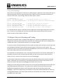
5.7 ANT Application
The private functions in the ANT application end up doing most of the work in the ANT system. The
encompassing application ends up being quite simple and just has to make sure that messages are being
sent, received and processed. It also has to get ANT up and running to the point where it can be used in
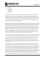
the system so initialization is very important. Once the ANT SM is initialized and operating, any
application running will be able to use the ANT radio. Figure 5.7.1 shows the state diagram for ANT SM.
notes_mpgl2_chapter5.docx
Release 1.0
Page 25 of 29
MPG LEVEL 2
Figure 5.7.1: State diagram for ANT SM
5.7.1. Initializing the ANT SM
A call to AntInitialize() will start the ANT state machine and should be made outside of the main program
loop like with any other application. The function call must occur after all of the driver functions have
been initialized since Ant requires MessageSender() and Debug() functionality. This initialization
function will follow the system rules and report its status with messages on the debug UART port so that
developers can quickly see the status. AntInitialize() will properly reset the synchronous serial interface
to ANT and test communications. If successful, it will send the base configuration commands to setup
the non-changing channel parameters of the system. The function header is shown here.
notes_mpgl2_chapter5.docx
Release 1.0
Page 26 of 29
MPG LEVEL 2
void AntInitialize(void);
/* Initialize the ANT system. ANT device is reset and communication checked through
a version request. The main channel parameters are then set up.
Requires:
- ANT_SPI peripheral is correctly configured
- Debug system is initialized so debug messages can be sent to UART
Promises:
- If all successful, GGu32SystemFlags.AntGood bit is set and ANT system is ready
- GGAntStateMachine = AntSMIdle
*/
5.7.2. Implementing AntSM
Once AntInitialize() is complete, the state machine pointer is set to the idle state and ready to run in the
main loop. The SM is quite simple and only has two states:
AntSMIdle(): Idle state that will process new messages if any are present and monitors ANT for incoming
messages.
AntSMReceiveMessage(): Completely receive an ANT message. Reception is very fast and should
complete in less than 600us for a 15-byte message. At 10Hz messaging, the message period is 100ms so
polling at 1ms allows plenty of margin to ensure no messages are missed and it gives plenty of time to
process each message and react accordingly.
There is no AntSMTransmitMessage() state because transmission is taken care of in the MessageSender
state machine. Neither the transmit or receive functions require multiple state cycles to complete, so
there will be no conflicts with sending and receiving messages at the same time. The only problem that
might pop up is if MessageSender tries to start a transmission but finds that ANT wants to transmit a
message to the Host. Receiving a message from ANT to the Host always gets priority. The transmit
function accounts for this by checking the SYNC byte it receives from ANT during the normal transmit
process and aborts the send attempt if the expected TX_SYNC turns out to be an RX_SYNC. If this
occurs, the MessageSender state will exit and the intended transmit message is left in the queue.
MessageSender will set a flag so that the ANT SM knows that a receive SYNC byte has already been
received, so the receiving function can start at that point and seamlessly receive the message from ANT.
When complete, MessageSender will retry sending the transmit message.
5.7.3 Global Access
The last two topics to discuss are how additional functionality is made available along with status
information that must be relayed to other applications that make use of the ANT sub-system. Part of
this design encroaches on the goal to have all applications completely abstracted from the other
applications, but again it comes down to balancing the firmware resources with functionality that really
is single-purpose hardware. In a multi-app system where several resources required the ANT radio, a
notes_mpgl2_chapter5.docx
Release 1.0
Page 27 of 29
MPG LEVEL 2
similar technique of a “busy” bit like what was used with the LCD is probably the easiest way to mitigate
conflicts. But since it barely makes sense to have two applications running in the system that both need
ANT, not even this provision is made. Really, this access functionality is the essence of the ANT
application API and still do a reasonable job at abstracting the ANT app from its clients.
5.7.3.1 Public Functions
Public functions that allow applications to configure the ANT radio are required so ANT will run in the
correct state. We have already discussed the message queuing and dequing functions, so what remains
are the command-like functions for ANT configuration and core operation.
void AntChannelConfig(bool): The function relies on the values of GGstAntSetupData which is of type
AntSetupDataType. This is the principle way that applications provide setup information to the ANT
application so the radio is configured to the calling app’s liking The typedef is shown below so you get
an idea of the parameters that need to be set up.
typedef struct
{
u8 AntChannel;
u8 AntChannelType;
u8 AntNetwork;
u8 AntSerialLo;
u8 AntSerialHi;
u8 AntDeviceType;
u8 AntTransmissionType;
u8 AntChannelPeriodLo;
u8 AntChannelPeriodHi;
u8 AntFrequency;
u8 AntTxPower;
} AntSetupDataType;
bool AntOpenChannel(void): tells the ANT radio to open an RF channel which sets everything into
action. Returns TRUE if the channel opens successfully. The calling application should start reading the
incoming data buffer because ANT will be relaying radio messages.
bool AntCloseChannel(void): requests closure of the active ANT channel. Returns TRUE when ANT
receives the request to close the channel. The application must still check
_ANT_FLAGS_CHANNEL_OPEN to ensure that it clears which confirms that RF communication is turned
off and ANT will be back to a semi-dormant and low power state.
bool AntUnassignChannel(void): if the application needs to reconfigure parameters it had previously
setup using AntChannelConfig(), the channel must first be unassigned using this function.
notes_mpgl2_chapter5.docx
Release 1.0
Page 28 of 29
MPG LEVEL 2
5.7.3.2 GGu32ANTFlags
Lastly, we have the flag register for ANT that is a Global Global so applications can observe ANT status in
case the app needs to react to events that take place in ANT that do not have other mechanisms to
share the information. Only the flags relevant to other apps are shown.
/* GGu32AntFlags */
#define _ANT_FLAGS_CMD_ERROR
#define _ANT_FLAGS_UNEXPECTED_MSG
*/
#define _ANT_FLAGS_RESTART
#define _ANT_FLAGS_CHANNEL_OPEN
#define _ANT_FLAGS_GOT_ACK
#define _ANT_FLAGS_OK_TO_SEND
/* A command received an error response */
/* The message parser handled an unexpected message
/*
/*
/*
/*
An ANT restart message was received */
Set when the ANT channel is open */
Set when an Acked data message gets acked */
Set when ANT is ready to send a message */
It is assumed that this register is read-only to other applications even though nothing exists to enforce
that. If this were a more public API, this status would be made through a function call to access a
private member variable inside the ANT app.
5.8 Chapter Exercise: Running and Testing
With that, the core ANT driver is complete and ready to use. It will be up to applications to correctly
configure the remaining channel parameters and take care of opening the ANT channel, adding code to
use data that comes in, and close the channel if it is no longer needed.
To ensure you have full understanding of all of the code that makes up the ANT driver and to check that
your development board is fully functional, load the Chapter 5 firmware on to your system. The
locations of interest in the code are all marked with #MPGL2# so you can use ctrl-shift-F to “find in files”
that symbol and go directly to all the exercise points.
Set a break point at AntInitialize() in main.c and step into the function to see how the code behaves. If
you debug any function that communicates with ANT, you have to step over the code so that the
system can run in real time since the AP2 is not part of the debugger.
Set up a watch window with the ANT transmit and receive buffers visible and see how the messages
appear. Make sure you see understand. You should also have the serial port connected to a PC to
monitor the system and capture the debugging information that is sent out.
Though you are not writing any code in this exercise, you are gaining valuable experience with ANT and
with the development board system. This experience is essential as you move forward and start
building the Pong application where you will be writing code that will very likely require some
debugging. If you want to experiment, you could write a small state machine application to arbitrarily
exchange data between a pair of ANT nodes and test your board with other student’s boards or with
your MPG Level 1 ANT system.
notes_mpgl2_chapter5.docx
Release 1.0
Page 29 of 29