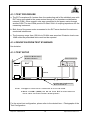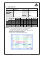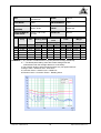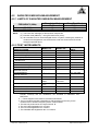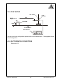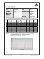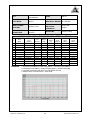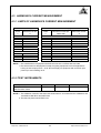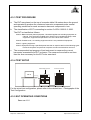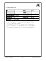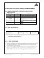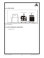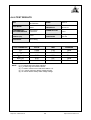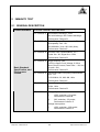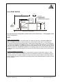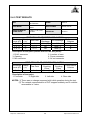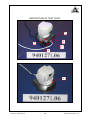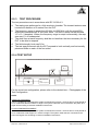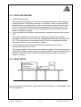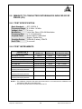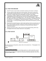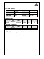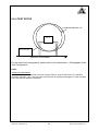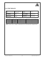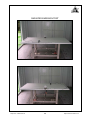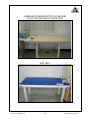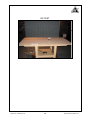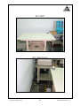
1
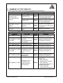
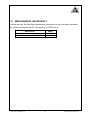
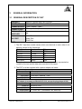
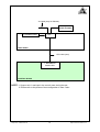
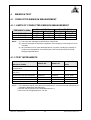
CE EMC TEST REPORT
REPORT NO. : CE940127L06
MODEL NO. : PZ6112, PZ6122, PZ7112, PZ7122, ANC-808V
RECEIVED : Jan. 27, 2005
TESTED : Mar. 08 to Apr. 17, 2005
ISSUED : Apr. 18, 2005
APPLICANT : VIVOTEK INC.
ADDRESS : 6F,No.192,Lien-Cheng Rd.,Chung-Ho,Taipei
County,Taiwan,R.O.C.
ISSUED BY : Advance Data Technology Corporation
LAB LOCATION : No. 81-1, Lu Liao Keng, 9 Ling, Wu Lung Tsuen,
Chiung Lin Hsiang, Hsin Chu Hsien,
Taiwan
This test report consists of 63 pages in total. It may be duplicated completely for legal use with the
approval of the applicant. It should not be reproduced except in full, without the written approval of our
laboratory. The client should not use it to claim product endorsement by CNLA, NVLAP, A2LA or any
government agencies. The test results in the report only apply to the tested sample. The test results in
this report are traceable to the national or international standards.
0536
ILAC MRA
Report No.: CE940127L06
1
Lab Code: 200376-0
No. 2177-01
Report Format Version 2.0.1
Table of Contents
1
2
2.1
3
3.1
3.2
3.3
3.4
4
4.1
4.1.1
4.1.2
4.1.3
4.1.4
4.1.5
4.1.6
4.1.7
4.2
4.2.1
4.2.2
4.2.3
4.2.4
4.2.5
4.2.6
4.2.7
4.3
4.3.1
4.3.2
4.3.3
4.3.4
4.3.5
4.3.6
4.4
4.4.1
4.4.2
4.4.3
4.4.4
4.4.5
4.4.6
CERTIFICATION..............................................................................................5
SUMMARY OF TEST RESULTS .....................................................................7
MEASUREMENT UNCERTAINTY...................................................................8
GENERAL INFORMATION ..............................................................................9
GENERAL DESCRIPTION OF EUT ................................................................9
DESCRIPTION OF TEST MODES ................................................................10
GENERAL DESCRIPTION OF APPLIED STANDARDS................................ 11
DESCRIPTION OF SUPPORT UNITS ..........................................................12
EMISSION TEST ...........................................................................................14
CONDUCTED EMISSION MEASUREMENT.................................................14
LIMITS OF CONDUCTED EMISSION MEASUREMENT ..............................14
TEST INSTRUMENTS...................................................................................14
TEST PROCEDURE......................................................................................15
DEVIATION FROM TEST STANDARD..........................................................15
TEST SETUP.................................................................................................15
EUT OPERATING CONDITIONS ..................................................................16
TEST RESULTS ............................................................................................17
RADIATED EMISSION MEASUREMENT......................................................19
LIMITS OF RADIATED EMISSION MEASUREMENT ...................................19
TEST INSTRUMENTS...................................................................................19
TEST PROCEDURE......................................................................................20
DEVIATION FROM TEST STANDARD..........................................................20
TEST SETUP.................................................................................................21
EUT OPERATING CONDITIONS ..................................................................21
TEST RESULTS ............................................................................................22
HARMONICS CURRENT MEASUREMENT..................................................24
LIMITS OF HARMONICS CURRENT MEASUREMENT ...............................24
TEST INSTRUMENTS...................................................................................24
TEST PROCEDURE......................................................................................25
TEST SETUP.................................................................................................25
EUT OPERATING CONDITIONS ..................................................................25
TEST RESULTS ............................................................................................26
VOLTAGE FLUCTUATION AND FLICKER MEASUREMENT .......................27
LIMITS OF VOLTAGE FLUCTUATION AND FLICKER MEASUREMENT.....27
TEST INSTRUMENTS...................................................................................27
TEST PROCEDURE......................................................................................27
TEST SETUP.................................................................................................28
EUT OPERATING CONDITIONS ..................................................................28
TEST RESULTS ............................................................................................29
Report No.: CE940127L06
2
Report Format Version 2.0.1
5
5.1
5.2
5.3
5.4
5.4.1
5.4.2
5.4.3
5.4.4
5.4.5
5.5
5.5.1
5.5.2
5.5.3
5.5.4
5.5.5
5.6
5.6.1
5.6.2
5.6.3
5.6.4
5.6.5
5.7
5.7.1
5.7.2
5.7.3
5.7.4
5.7.5
5.8
5.8.1
5.8.2
5.8.3
5.8.4
5.8.5
5.9
5.9.1
5.9.2
5.9.3
5.9.4
IMMUNITY TEST ...........................................................................................30
GENERAL DESCRIPTION ............................................................................30
GENERAL PERFORMANCE CRITERIA DESCRIPTION ..............................31
EUT OPERATING CONDITION.....................................................................31
ELECTROSTATIC DISCHARGE IMMUNITY TEST (ESD) ............................32
TEST SPECIFICATION .................................................................................32
TEST INSTRUMENTS...................................................................................32
TEST PROCEDURE......................................................................................33
TEST SETUP.................................................................................................34
TEST RESULTS ............................................................................................35
RADIATED, RADIO-FREQUENCY, ELECTROMAGNETIC FIELD IMMUNITY
TEST (RS) .....................................................................................................37
TEST SPECIFICATION .................................................................................37
TEST INSTRUMENTS...................................................................................37
TEST PROCEDURE......................................................................................38
TEST SETUP.................................................................................................38
TEST RESULTS ............................................................................................39
ELECTRICAL FAST TRANSIENT/BURST IMMUNITY TEST (EFT) ..............40
TEST SPECIFICATION .................................................................................40
TEST INSTRUMENTS...................................................................................40
TEST PROCEDURE......................................................................................40
TEST SETUP.................................................................................................41
TEST RESULTS ............................................................................................42
SURGE IMMUNITY TEST .............................................................................43
TEST SPECIFICATION .................................................................................43
TEST INSTRUMENTS...................................................................................43
TEST PROCEDURE......................................................................................44
TEST SETUP.................................................................................................44
TEST RESULTS ............................................................................................45
IMMUNITY TO CONDUCTED DISTURBANCES INDUCED BY RF FIELDS
(CS) .............................................................................................................46
TEST SPECIFICATION .................................................................................46
TEST INSTRUMENTS...................................................................................46
TEST PROCEDURE......................................................................................47
TEST SETUP.................................................................................................47
TEST RESULTS ............................................................................................48
POWER FREQUENCY MAGNETIC FIELD IMMUNITY TEST ......................49
TEST SPECIFICATION .................................................................................49
TEST INSTRUMENTS...................................................................................49
TEST PROCEDURE......................................................................................49
TEST SETUP.................................................................................................50
Report No.: CE940127L06
3
Report Format Version 2.0.1
5.9.5
5.10
5.10.1
5.10.2
5.10.3
5.10.4
5.10.5
6
7
TEST RESULTS ............................................................................................51
VOLTAGE DIP/SHORT INTERRUPTIONS/VOLTAGE VARIATIONS (DIP)
IMMUNITY TEST ...........................................................................................52
TEST SPECIFICATION .................................................................................52
TEST INSTRUMENTS...................................................................................52
TEST PROCEDURE......................................................................................52
TEST SETUP.................................................................................................53
TEST RESULTS ............................................................................................54
PHOTOGRAPHS OF THE TEST CONFIGURATION ....................................55
APPENDIX - INFORMATION ON THE TESTING LABORATORIES .............63
Report No.: CE940127L06
4
Report Format Version 2.0.1
CERTIFICATION - Continued
The test record, data evaluation & Equipment Under Test (EUT) configurations
represented herein are true and accurate accounts of the measurements of the
sample’s EMC characteristics under the conditions specified in this report.
PREPARED BY
:
,
DATE:
Apr. 18, 2005
,
DATE:
Apr. 18, 2005
,
DATE:
Apr. 18, 2005
,
DATE:
Apr. 18, 2005
( Claire Kuan )
TECHNICAL
ACCEPTANCE
:
Responsible for EMI
TECHNICAL
ACCEPTANCE
( Mitch Jen )
:
Responsible for EMS
APPROVED BY
( Ivan Peng )
:
( Eric Lin, Manager )
Note *: The power consumption of EUT is 9.719W, which is less than 75W and no limits apply.
Therefore it is deemed to comply with EN 61000-3-2: 2000 without any testing.
Report No.: CE940127L06
6
Report Format Version 2.0.1
2 SUMMARY OF TEST RESULTS
The EUT has been tested according to the following specifications:
EMISSION
Standard
Test Type
Result
Remarks
EN55022:1994
+A1:1995+A2:1997,
Class B
Conducted Test
PASS
Radiated Test
PASS
Meets Class B Limit
Minimum passing margin is
-16.46 dB at 0.861 MHz
Meets Class B Limit
Minimum passing margin is
-0.5 dB at 999.98 MHz
EN61000-3-2:2000,
Class A
Harmonic current
emissions
PASS
The power consumption of
EUT is less than 75W and no
limits apply
EN61000-3-3:1995 +
A1:2001
Voltage fluctuations &
flicker
PASS
Meets the requirements.
IMMUNITY (EN 55024:1998+A1:2001+A2:2003)
Standard
Test Type
Result
Remarks
Electrostatic discharge
immunity test
Radiated, radioIEC 61000-4-3: 2002 frequency,
electromagnetic field
+A1:2002
immunity test
IEC 61000-4-4: 1995 Electrical fast transient
+ A1:2000+A2:2001 / burst immunity test.
IEC 61000-4-2: 2001
IEC 61000-4-5: 2001
Surge immunity test
Immunity to conducted
IEC 61000-4-6: 2003 disturbances, induced
+A1:2004
by radio-frequency
fields
Power frequency
IEC 61000-4-8: 2001 magnetic field
immunity test.
Voltage dips, short
interruptions and
IEC 61000-4-11:2001
voltage variations
immunity tests
Report No.: CE940127L06
7
PASS
Meets the requirements of
Performance Criterion B
PASS
Meets the requirements of
Performance Criterion A
PASS
PASS
Meets the requirements of
Performance Criterion A
Meets the requirements of
Performance Criterion A
PASS
Meets the requirements of
Performance Criterion A
PASS
Meets the requirements of
Performance Criterion A
PASS
Meets the requirements of
Voltage Dips:
1. >95% reduction Performance Criterion A
2. 30% reduction Performance Criterion A
Voltage Interruptions:
1. >95% reduction Performance Criterion B
Report Format Version 2.0.1
2.1 MEASUREMENT UNCERTAINTY
Where relevant, the following measurement uncertainty levels have been estimated
for tests performed on the EUT as specified in CISPR 16-4:
Value
2.53 dB
3.46 dB
Measurement
Conducted emissions
Radiated emissions (30MHz-1GHz)
Report No.: CE940127L06
8
Report Format Version 2.0.1
3
GENERAL INFORMATION
3.1 GENERAL DESCRIPTION OF EUT
PRODUCT
Network Camera with Pan/Tilt/Zoom
MODEL NO.
PZ6112, PZ6122, PZ7112, PZ7122, ANC-808V
POWER SUPPLY Power Adapter, Class I
DC output cable (Unshielded, 1.8m, with one core)
POWER CORD
DATA CABLE
SUPPLIED
NA
I/O PORT
Video Port
Audio Port
RJ45 Port
NOTE:
1. The EUT has three model names which are identical to each other in all
aspects except for the followings:
Model Name
Brand
Difference
PZ6112
Vivotek
NTSC
PZ6122
Vivotek
PAL
PZ7112
Vivotek
NTSC
PZ7122
Vivotek
PAL
ANC-808V
Afreey
ODM
From the above models, model: PZ6112 was selected as representative
model for the test and its data was recorded in this report.
2. The EUT must be supplied with a power adapter as below :
Adapter 1:
Brand: DVE
Model No.: DSA-0151F-12 U
Input power : AC100-240V ~50/60Hz
0.4A
Output power : DC +12V/1.5A (unshielded 1.8m; with core)
Adapter 2:
(the adapter is as same as DSA-0151F-12 U, except for plug shape of UK)
Brand: DVE
Model No.: DSA-0151F-12 K
Input power : AC100-240V ~50/60Hz
0.4A
Output power : DC +12V/1.25A (unshielded 1.8m; with core)
Report No.: CE940127L06
9
Report Format Version 2.0.1
3. For a more detailed features description, please refer to the
manufacturer's specifications or the User's Manual.
3.2 DESCRIPTION OF TEST MODES
The EUT was tested under following test modes:
Mode 1 : With LAN Ping Mode
Report No.: CE940127L06
10
Report Format Version 2.0.1
3.3 GENERAL DESCRIPTION OF APPLIED STANDARDS
The EUT is a kind of IT equipment and, according to the specifications of the
manufacturers, must comply with the requirements of the following standards:
EN 55022:1994+A1:1995
+A2:1997, Class B
EN 61000-3-2: 2000, Class A
EN 61000-3-3: 1995+A1: 2001
EN 55024:1998+A1:2001
+A2:2003
IEC 61000-4-2:2001
IEC 61000-4-3:2002+A1:2002
IEC 61000-4-4:1995+A1:2000
+A2:2001
IEC 61000-4-5:2001
IEC 61000-4-6:2003+A1:2004
IEC 61000-4-8:2001
IEC 61000-4-11:2001
All tests have been performed and recorded as per the above standards.
Report No.: CE940127L06
11
Report Format Version 2.0.1
3.4 DESCRIPTION OF SUPPORT UNITS
The EUT has been tested as an independent unit together with other necessary
accessories or support units. The following support units or accessories were used to
form a representative test configuration during the tests.
NO.
PRODUCT
BRAND
MODEL NO.
SERIAL NO.
FCC ID
1
Notebook Computer
ASUS
A2400H
49NG038481
NA
2
MICROPHONE
KOKA
DM-510
N/A
N/A
NO. SIGNAL CABLE DESCRIPTION OF THE ABOVE SUPPORT UNITS
1
NA
2
NA
NOTE: All power cords of the above support units are non-shielded (1.8m).
Report No.: CE940127L06
12
Report Format Version 2.0.1
AV Cable (Only for EMI test)
Adapter
Under test table
2. MICROPHONE
EUT
TEST TABLE
UTP Cable (10m)
1. NOTEBOOK
COMPUTER
CONTROL ROOM
NOTE: 1. Support unit 1 was kept in the control room during the test.
2. Please refer to the photos of test configuration in Item 5 also.
Report No.: CE940127L06
13
Report Format Version 2.0.1
4
EMISSION TEST
4.1 CONDUCTED EMISSION MEASUREMENT
4.1.1 LIMITS OF CONDUCTED EMISSION MEASUREMENT
FREQUENCY (MHz)
0.15 - 0.5
0.50 - 5.0
5.0 - 30.0
NOTE:
Class A (dBuV)
Quasi-peak Average
79
66
73
60
73
60
Class B (dBuV)
Quasi-peak Average
66 - 56
56 - 46
56
46
60
50
(1) The lower limit shall apply at the transition frequencies.
(2) The limit decreases in line with the logarithm of the frequency in the range of 0.15 to
0.50 MHz.
(3) All emanations from a class A/B digital device or system, including any network of
conductors and apparatus connected thereto, shall not exceed the level of field
strengths specified above.
4.1.2 TEST INSTRUMENTS
DESCRIPTION &
MANUFACTURER
MODEL NO.
SERIAL NO.
CALIBRATED
UNTIL
ROHDE & SCHWARZ
Test Receiver
ESCS 30
847124/029
Dec. 07, 2005
ROHDE & SCHWARZ LISN
(for EUT)
ESHS-Z5
848773/004
Nov. 08, 2005
KYORITSU LISN (for peripheral)
KNW-407
8/1395/12
Jul. 23, 2005
RF Cable (JETBAO)
RG233/U
Cable_CA_01
Jul. 02, 2005
Terminator(for KYORITSU)
50
3
May 10, 2005
Software
Cond-V2e
NA
NA
NOTE: 1. The calibration interval of the above test instruments is 12 months and the calibrations are
traceable to NML/ROC and NIST/USA.
2. The test was performed in ADT Shielded Room No. A.
3. The VCCI Con A Registration No. is C-817.
Report No.: CE940127L06
14
Report Format Version 2.0.1
4.1.3 TEST PROCEDURE
a. The EUT was placed 0.4 meters from the conducting wall of the shielded room with
EUT being connected to the power mains through a line impedance stabilization
network (LISN). Other support units were connected to the power mains through
another LISN. The two LISNs provide 50 Ohm/ 50uH of coupling impedance for the
measuring instrument.
b. Both lines of the power mains connected to the EUT were checked for maximum
conducted interference.
c. The frequency range from 150 kHz to 30 MHz was searched. Emission levels over
10dB under the prescribed limits could not be reported.
4.1.4 DEVIATION FROM TEST STANDARD
No deviation
4.1.5 TEST SETUP
Ve rtic a l R e fe re n c e
Te s t R e c e iv e r
G r o u n d P la n e
EUT
40cm
80cm
L IS N
H o r iz o n ta l R e fe re n c e
G r o u n d P la n e
N o te : 1 .S u p p o r t u n its w e r e c o n n e c te d to s e c o n d L IS N .
2 .B o t h o f L IS N s ( A M N ) a re 8 0 c m f ro m E U T a n d a t le a s t 8 0
fro m o th e r u n its a n d o th e r m e ta l p la n e s
For the actual test configuration, please refer to the related item – Photographs of the
Test Configuration.
Report No.: CE940127L06
15
Report Format Version 2.0.1
4.1.6 EUT OPERATING CONDITIONS
a. Placed the EUT on the testing table.
b. Prepared another computer system to act as a communication partner and
placed it outside of testing area.
c. The communication partner run “Ping.exe” test program to enable EUT under
transmission/receiving condition continuously via UTP cable.
Report No.: CE940127L06
16
Report Format Version 2.0.1
4.1.7 TEST RESULTS
EUT
Network Camera with
Pan/Tilt/Zoom
MODEL
PZ6112
TEST MODE
Mode 1
6dB BANDWIDTH
9 kHz
230Vac, 50 Hz
PHASE
Line (L)
TESTED BY
Wen Yu
INPUT POWER
(SYSTEM)
ENVIRONMENTAL 25 deg. C, 85 % RH,
976 hPa
CONDITIONS
Freq.
Corr.
Reading Value
[MHz]
0.153
0.295
0.861
1.377
2.595
4.859
Factor
(dB)
9.47
9.20
9.22
9.24
9.27
9.41
[dB (uV)]
Q.P.
AV.
37.83
31.45
30.32
28.11
25.07
25.66
-
No
1
2
3
4
5
6
Emission
Level
[dB (uV)]
Q.P.
AV.
47.30
40.65
39.54
37.35
34.34
35.07
-
Limit
Margin
[dB (uV)]
Q.P.
AV.
65.85 55.85
60.40 50.40
56.00 46.00
56.00 46.00
56.00 46.00
56.00 46.00
(dB)
Q.P.
-18.55
-19.74
-16.46
-18.65
-21.66
-20.93
AV.
-
REMARKS: 1. Q.P. and AV. are abbreviations of quasi-peak and average individually.
2. "-": The Quasi-peak reading value also meets average limit and
measurement with the average detector is unnecessary.
3. The emission levels of other frequencies were very low against the limit.
4. Margin value = Emission level - Limit value
5. Correction factor = Insertion loss + Cable loss
6. Emission Level = Correction Factor + Reading Value.
Report No.: CE940127L06
17
Report Format Version 2.0.1
EUT
Network Camera with
Pan/Tilt/Zoom
MODEL
PZ6112
TEST MODE
Mode 1
6dB BANDWIDTH
9 kHz
230Vac, 50 Hz
PHASE
Neutral (N)
TESTED BY
Wen Yu
INPUT POWER
(SYSTEM)
ENVIRONMENTAL 25 deg. C, 85 % RH,
976 hPa
CONDITIONS
Freq.
Corr.
Reading Value
[MHz]
0.154
0.302
0.689
0.896
1.365
2.502
Factor
(dB)
9.19
9.21
9.20
9.20
9.24
9.34
[dB (uV)]
Q.P.
AV.
37.79
32.90
30.03
27.82
25.44
24.57
-
No
1
2
3
4
5
6
Emission
Level
[dB (uV)]
Q.P.
AV.
46.98
42.11
39.23
37.02
34.68
33.91
-
Limit
Margin
[dB (uV)]
Q.P.
AV.
65.77 55.77
60.18 50.18
56.00 46.00
56.00 46.00
56.00 46.00
56.00 46.00
(dB)
Q.P.
-18.78
-18.07
-16.77
-18.98
-21.32
-22.09
AV.
-
REMARKS: 1. Q.P. and AV. are abbreviations of quasi-peak and average individually.
2. "-": The Quasi-peak reading value also meets average limit and
measurement with the average detector is unnecessary.
3. The emission levels of other frequencies were very low against the limit.
4. Margin value = Emission level - Limit value
5. Correction factor = Insertion loss + Cable loss
6. Emission Level = Correction Factor + Reading Value.
Report No.: CE940127L06
18
Report Format Version 2.0.1
4.2
RADIATED EMISSION MEASUREMENT
4.2.1 LIMITS OF RADIATED EMISSION MEASUREMENT
FREQUENCY (MHz)
30 - 230
230 - 1000
NOTE:
Class A (at 10m)
dBuV/m
40
47
Class B (at 10m)
dBuV/m
30
37
(1) The lower limit shall apply at the transition frequencies.
(2) Emission level (dBuV/m) = 20 log Emission level (uV/m).
(3) All emanations from a class A/B digital device or system, including any network of
conductors and apparatus connected thereto, shall not exceed the level of field
strengths specified above.
4.2.2 TEST INSTRUMENTS
DESCRIPTION &
MANUFACTURER
HP Spectrum Analyzer
*ADVANTEST Spectrum Analyzer
CHASE RF Pre_Amplifier
*HP Pre_Amplifier
*ROHDE & SCHWARZ
Test Receiver
*CHASE Broadband Antenna
*Schwarzbeck Horn_Antenna
Schwarzbeck Horn_Antenna
SCHWARZBECK
Biconical Antenna
SCHWARZBECK
Periodic Antenna
CALIBRATED
UNTIL
May 04, 2005
Jun. 29, 2005
Jun 03, 2005
Oct. 13, 2005
Oct. 12, 2005
MODEL NO.
SERIAL NO.
8590L
R3271A
CPA9232
8449B
ESVS 30
3647U00646
85060311
1056
3008A01922
841977/002
CBL6111C
BBHA9120-D1
BBHA 9170
2730
D123
BBHA9170153
VHBA9123
459
Jun. 03, 2005
Sep. 23, 2005
Jan. 31, 2006
Jun. 26, 2006
UPA6108
1148
Jun. 26, 2006
*RF Switches
*RF Cable(CHASE)
MP59B
6100175593
Jul. 16, 2005
9913-30M N-N
STBCAB-30MJul. 16, 2005
Cable
1GHz-021
*Software
ADT_Radiated_V NA
NA
5.14
*CHANCE MOST Antenna Tower
AT-100
CM-A007
NA
*CHANCE MOST Turn Table
TC-008
CM-T007
NA
*CORCOM AC Filter
MRI2030
024/019
NA
Note: 1. The calibration interval of the above test instruments is 12 months (36 months for
Periodic Antenna) and the calibrations are traceable to NML/ROC and
NIST/USA.
2. * = These equipment are used for the final measurement.
3. The horn antenna and HP preamplifier (model: 8449B) are used only for the
measurement of emission frequency above 1GHz if tested.
4. The test was performed in ADT Open Site No. B.
5. The VCCI Site Registration No. is R-847.
6. The FCC Site Registration No. is 92753.
7. The CANADA Site Registration No. is IC 4824-2.
Report No.: CE940127L06
19
Report Format Version 2.0.1
4.2.3 TEST PROCEDURE
a. The EUT was placed on the top of a rotating table 0.8 meters above the ground at
a 10-meter open field site. The table was rotated 360 degrees to determine the
position of the highest radiation.
b. The EUT was set 10 meters away from the interference-receiving antenna, which
was mounted on the top of a variable-height antenna tower.
c. The antenna is a broadband antenna, and its height is varied from one meter to
four meters above the ground to determine the maximum value of the field
strength. Both horizontal and vertical polarization of the antenna are set to make
the measurement.
d. For each suspected emission, the EUT was arranged to its worst case and then
the antenna was tuned to heights from 1 meter to 4 meters and the turn table was
turned from 0 degrees to 360 degrees to find the maximum reading.
e. The test-receiver system was set to Peak Detect Function and Specified
Bandwidth with Maximum Hold Mode.
f. If the emission level of the EUT in peak mode was 10 dB lower than the limit
specified, then testing could be stopped and the peak values of the EUT would be
reported. Otherwise the emissions that did not have 10 dB margin would be retested one by one using the quasi- peak method or average method as specified
and then reported In Data sheet peak mode and QP mode.
4.2.4 DEVIATION FROM TEST STANDARD
No deviation
Report No.: CE940127L06
20
Report Format Version 2.0.1
4.2.5 TEST SETUP
Ant. Tower
EUT&
Support Units
1-4m
Variable
10m
Turn Table
80cm
Ground Plane
Test Receiver
For the actual test configuration, please refer to the related item – Photographs of the
Test Configuration.
4.2.6 EUT OPERATING CONDITIONS
Same as 4.1.6
Report No.: CE940127L06
21
Report Format Version 2.0.1
4.2.7 TEST RESULTS
EUT
Network Camera with
Pan/Tilt/Zoom
MODEL
TEST MODE
Mode 1
FREQUENCY RANGE 30-1000 MHz
230Vac, 50 Hz
DETECTOR
FUNCTION&
BANDWIDTH
Quasi-Peak,
20 deg. C, 89% RH,
976 hPa
TESTED BY
Phoenix Huang
INPUT POWER
(SYSTEM)
ENVIRONMENTAL
CONDITIONS
PZ6112
120kHz
ANTENNA POLARITY & TEST DISTANCE: HORIZONTAL AT 10 M
No.
Freq.
(MHz)
1
2
3
4
5
6
7
8
9
10
11
125.05
200.00
250.13
324.30
499.99
600.00
625.00
700.00
800.00
900.00
1000.00
REMARKS:
Emission
Level
(dBuV/m)
23.80 QP
23.40 QP
29.00 QP
31.90 QP
33.70 QP
32.20 QP
30.10 QP
30.60 QP
28.80 QP
30.20 QP
33.60 QP
Limit
(dBuV/m)
Margin
(dB)
30.00
30.00
37.00
37.00
37.00
37.00
37.00
37.00
37.00
37.00
37.00
-6.20
-6.60
-8.00
-5.10
-3.30
-4.80
-6.90
-6.40
-8.20
-6.80
-3.40
Antenna
Height
(m)
4.00 H
4.00 H
4.00 H
2.50 H
2.36 H
1.63 H
1.42 H
1.31 H
1.00 H
1.00 H
1.00 H
Table
Angle
(Degree)
118
216
97
144
52
321
245
191
152
123
329
Raw
Value
(dBuV)
11.80
13.20
15.40
15.70
12.60
9.10
6.70
6.50
3.20
3.30
5.00
Correction
Factor
(dB/m)
11.90
10.20
13.60
16.20
21.10
23.10
23.40
24.10
25.60
26.90
28.60
1. Emission level(dBuV/m)=Raw Value(dBuV) + Correction Factor(dB/m)
2. Correction Factor(dB/m) = Antenna Factor (dB/m) + Cable Factor (dB)
3. The other emission levels were very low against the limit.
4. Margin value = Emission level – Limit value.
Report No.: CE940127L06
22
Report Format Version 2.0.1
EUT
Network Camera with
Pan/Tilt/Zoom
MODEL
TEST MODE
Mode 1
FREQUENCY RANGE 30-1000 MHz
230Vac, 50 Hz
DETECTOR
FUNCTION&
BANDWIDTH
Quasi-Peak,
20 deg. C, 89% RH,
976 hPa
TESTED BY
Phoenix Huang
INPUT POWER
(SYSTEM)
ENVIRONMENTAL
CONDITIONS
PZ6112
120kHz
ANTENNA POLARITY & TEST DISTANCE: VERTICAL AT 10 M
No.
Freq.
(MHz)
1
2
3
4
5
6
7
8
9
10
11
12
125.10
200.00
250.13
300.00
400.00
499.99
600.00
624.99
700.00
800.00
900.10
999.98
REMARKS:
Emission
Level
(dBuV/m)
23.50 QP
24.60 QP
29.20 QP
26.50 QP
26.90 QP
29.60 QP
31.10 QP
30.00 QP
33.00 QP
31.10 QP
32.40 QP
36.50 QP
Limit
(dBuV/m)
Margin
(dB)
30.00
30.00
37.00
37.00
37.00
37.00
37.00
37.00
37.00
37.00
37.00
37.00
-6.50
-5.40
-7.80
-10.50
-10.10
-7.40
-5.90
-7.00
-4.00
-5.90
-4.60
-0.50
Antenna
Height
(m)
1.00 V
1.00 V
1.00 V
1.00 V
1.00 V
1.59 V
2.92 V
2.50 V
2.62 V
2.29 V
2.24 V
1.85 V
Table
Angle
(Degree)
261
208
265
33
212
260
268
77
250
177
213
313
Raw
Value
(dBuV)
11.60
14.40
15.60
10.70
8.20
8.50
8.00
6.60
8.90
5.50
5.40
7.90
Correction
Factor
(dB/m)
11.90
10.20
13.60
15.80
18.70
21.10
23.10
23.40
24.10
25.60
26.90
28.60
1. Emission level(dBuV/m)=Raw Value(dBuV) + Correction Factor(dB/m)
2. Correction Factor(dB/m) = Antenna Factor (dB/m) + Cable Factor (dB)
3. The other emission levels were very low against the limit.
4. Margin value = Emission level – Limit value.
Report No.: CE940127L06
23
Report Format Version 2.0.1
4.3 HARMONICS CURRENT MEASUREMENT
4.3.1 LIMITS OF HARMONICS CURRENT MEASUREMENT
Limits for Class A equipment
Harmonics Max. permissible
Order
harmonics current
n
A
Odd harmonics
3
2.30
5
1.14
7
0.77
9
0.40
11
0.33
13
0.21
15<=n<=39 0.15x15/n
Even harmonics
2
1.08
4
0.43
6
0.30
8<=n<=40 0.23x8/n
Harmonics
Order
n
3
5
7
9
11
13
15<=n<=39
Limits for Class D equipment
Max. permissible
Max. permissible
harmonics current per
harmonics current
watt mA/W
A
Odd Harmonics only
3.4
2.30
1.9
1.14
1.0
0.77
0.5
0.40
0.35
0.33
0.30
0.21
3.85/n
0.15x15/n
NOTE: 1.The classifications of equipment are defined in Section 5 of EN 61000-3-2:2000.
2.The above limits for all equipment except for lighting equipment are for all applications
having an active input power > 75 W. No limits apply for equipment with an active input
power up to and including 75 W.
4.3.2 TEST INSTRUMENTS
Description & Manufacturer
EMC PARTNER
EMC Emission Tester
Model No.
HAR1000
Serial No.
086
Calibrated Until
Jan. 12, 2006
NOTE: 1. The calibration interval of the above test instruments is 12 months and the calibrations are
traceable to NML/ROC and NIST/USA.
2. The test was performed in EMS room.
Report No.: CE940127L06
24
Report Format Version 2.0.1
4.3.3 TEST PROCEDURE
a. The EUT was placed on the top of a wooden table 0.8 meters above the ground
and operated to produce the maximum harmonic components under normal
operating conditions for each successive harmonic component in turn.
b. The classification of EUT is according to section 5 of EN 61000-3-2: 2000.
The EUT is classified as follows:
Class A: Balanced three-phase equipment, Household appliances excluding equipment as
Class D, Tools excluding portable tools, Dimmers for incandescent lamps, audio
equipment, equipment not specified in one of the three other classes.
Class B: Portable tools.; Arc welding equipment which is not professional equipment
Class C: Lighting equipment.
Class D: Equipment having a specified power less than or equal to 600 W of the following types:
Personal computers and personal computer monitors and television receivers.
c. The correspondent test program of test instrument to measure the current
harmonics emanated from EUT is chosen. The measure time shall be not less
than the time necessary for the EUT to be exercised.
4.3.4 TEST SETUP
Measuring System
AC Power Source
EUT
For the actual test configuration, please refer to the related item – Photographs of the
Test Configuration.
4.3.5 EUT OPERATING CONDITIONS
Same as 4.1.6
Report No.: CE940127L06
25
Report Format Version 2.0.1
4.3.6 TEST RESULTS
EUT
Network Camera with
Pan/Tilt/Zoom
MODEL
PZ6112
TEST MODE
Mode 1
POWER
FREQUENCY
49.818 Hz
FUNDAMENTAL
VOLTAGE/AMPERE
229.7 Vrms /
0.104 Arms
POWER FACTOR
0.405
POWER
CONSUMPTION
9.719 W
ENVIRONMENTAL
CONDITIONS
25 deg. C, 44 % RH,
976 hPa
TESTED BY
Kevin Huang
1. Limits are not specified for equipment with a rated power of 75W or
less (other than lighting equipment).
2. According to EN 61000-3-2: 2000 the manufacturer shall specify the
power of the apparatus. This value shall be used for establishing limits.
The specified power shall be within +/-10% of the measured power.
Report No.: CE940127L06
26
Report Format Version 2.0.1
4.4 VOLTAGE FLUCTUATION AND FLICKER MEASUREMENT
4.4.1 LIMITS OF VOLTAGE FLUCTUATION AND FLICKER
MEASUREMENT
TEST ITEM
Pst
Plt
Tdt (ms)
dmax (%)
dc (%)
LIMIT
0.471
0.471
NOTE
Pst means short-term flicker indicator.
Plt means long-term flicker indicator.
500
Tdt means maximum time that dt
exceeds 3.3 %.
4%
dmax means maximum relative voltage
change.
dc means relative steady-state voltage
change
3.3%
4.4.2 TEST INSTRUMENTS
Description & Manufacturer
EMC PARTNER
EMC Emission Tester
Model No.
HAR1000
Serial No.
086
Calibrated Until
Jan. 12, 2006
NOTE: 1. The calibration interval of the above test instruments is 12 months and the calibrations are
traceable to NML/ROC and NIST/USA.
2. The test was performed in EMS room.
4.4.3
TEST PROCEDURE
a. The EUT was placed on the top of a wooden table 0.8 meters above the ground
and operated to produce the most unfavorable sequence of voltage changes
under normal operating conditions.
b. During the flick measurement, the measure time shall include that part of whole
operation cycle in which the EUT produce the most unfavorable sequence of
voltage changes. The observation period for short-term flicker indicator is 10
minutes and the observation period for long-term flicker indicator is 2 hours.
Report No.: CE940127L06
27
Report Format Version 2.0.1
4.4.4 TEST SETUP
Measuring System
AC Power Source
EUT
For the actual test configuration, please refer to the related item – Photographs of the
Test Configuration.
4.4.5 EUT OPERATING CONDITIONS
Same as 4.1.6
Report No.: CE940127L06
28
Report Format Version 2.0.1
4.4.6 TEST RESULTS
EUT
Network Camera with
Pan/Tilt/Zoom
MODEL
PZ6112
TEST MODE
Mode 1
POWER
FREQUENCY
49.831 Hz
FUNDAMENTAL
VOLTAGE/AMPERE
229.7 Vrms /
0.103 Arms
POWER FACTOR
0.412
OBSERVATION
PERIOD (TP)
12 min.
ENVIRONMENTAL
CONDITIONS
25 deg. C, 44 % RH,
976 hPa
TESTED BY
Kevin Huang
TEST PARAMETER
MEASUREMENT
VALUE
LIMIT
REMARKS
Pst
0.209
1.00
Pass
Plt
0.209
0.65
Pass
Tdt (ms)
0.00
500
Pass
dmax (%)
0.00
4%
Pass
dc (%)
0.00
3.3%
Pass
NOTE:
(1)
(2)
(3)
(4)
(5)
Pst means short-term flicker indicator.
Plt means long-term flicker indicator.
Tdt means maximum time that dt exceeds 3.3 %.
dmax means maximum relative voltage change.
dc means relative steady-state voltage change.
Report No.: CE940127L06
29
Report Format Version 2.0.1
5 IMMUNITY TEST
5.1 GENERAL DESCRIPTION
Product Standard: EN 55024:1998+A1:2001+A2:2003
IEC 61000-4-2
Electrostatic Discharge - ESD:
8kV air discharge, 4kV Contact discharge,
Performance Criterion B
IEC 61000-4-3
Radio-Frequency Electromagnetic Field
Susceptibility Test - RS:
80-1000 MHz, 3V/m, 80% AM (1kHz),
Performance Criterion A
IEC 61000-4-4
Electrical Fast Transient/Burst - EFT,
Power line: 1kV, Signal line: 0.5kV,
Performance Criterion B
IEC 61000-4-5
Basic Standard,
Specification, and
Performance
Criteria:
Surge Immunity Test:
1.2/50 us Open Circuit Voltage, 8 /20 us
Short Circuit Current, Power Line - 1 kV, line
to earth - 2kV,
Performance Criterion B
IEC 61000-4-6
Conducted Radio Frequency Disturbances
Test - CS:
0.15-80 MHz, 3V, 80% AM, 1kHz,
Performance Criterion A
IEC 61000-4-8
Power Frequency Magnetic Field Test,
50 Hz, 1A/m,
Performance Criterion B
IEC 61000-4-11 Voltage Dips:
i)
>95% reduction -0.5 period,
Performance Criteria B
ii)
30% reduction - 25 period,
Performance Criterion C
Voltage Interruptions:
i)
Report No.: CE940127L06
30
>95% reduction - 250 period,
Performance Criterion C
Report Format Version 2.0.1
5.2 GENERAL PERFORMANCE CRITERIA DESCRIPTION
According to Clause 7.1 of EN 55024 standard, the following describes
the general performance criteria.
The equipment shall continue to operate as intended without
operator intervention. No degradation of performance or loss of
function is allowed below a performance level specified by the
manufacturer when the equipment is used as intended. The
performance level may be replaced by a permissible loss of
CRITERION A
performance. If the minimum performance level or the
permissible performance loss is not specified by the
manufacturer, then either of these may be derived from the
product description and documentation, and by what the user
may reasonably expect from the equipment if used as intended.
After the test, the equipment shall continue to operate as
intended without operator intervention. No degradation of
performance or loss of function is allowed, after the application of
the phenomenon below a performance level specified by the
manufacturer, when the equipment is used as intended. The
performance level may be replaced by a permissible loss of
performance.
CRITERION B
During the test, degradation of performance is allowed. However,
no change of operating state if stored data is allowed to persist
after the test. If the minimum performance level (or the
permissible performance loss) is not specified by the
manufacturer, then either of these may be derived from the
product description and documentation, and by what the user
may reasonably expect from the equipment if used as intended.
Loss of function is allowed, provided the function is selfrecoverable, or can be restored by the operation of the controls
CRITERION C by the user in accordance with the manufacturer’s instructions.
Functions, and/or information stored in non-volatile memory, or
protected by a battery backup, shall not be lost.
5.3
EUT OPERATING CONDITION
Same as 4.1.6
Report No.: CE940127L06
31
Report Format Version 2.0.1
5.4 ELECTROSTATIC DISCHARGE IMMUNITY TEST (ESD)
5.4.1 TEST SPECIFICATION
Basic Standard:
IEC 61000-4-2
Discharge Impedance: 330 ohm / 150 pF
Discharge Voltage:
Air Discharge – 2, 4 kV (Direct)
Contact Discharge – 2, 4, 8 kV (Direct/Indirect)
Polarity:
Positive / Negative
Number of Discharge: Air Discharge: min. 20 times at each test point
Contact Discharge: min. 50 times at each test point
Discharge Mode:
Single Discharge
Discharge Period:
1-second minimum
5.4.2 TEST INSTRUMENTS
DESCRIPTION &
MANUFACTURER
NoiseKen, ESD Simulator
MODEL NO.
SERIAL NO.
CALIBRATED UNTIL
ESS-100L(A)
0189C01491
Jun. 30, 2005
NOTE: 1. The calibration interval of the above test instruments is 12 months and the calibrations are
traceable to NML/ROC and NIST/USA.
2. The test was performed in ESD room.
Report No.: CE940127L06
32
Report Format Version 2.0.1
5.4.3 TEST PROCEDURE
The discharges shall be applied in two ways:
a. Contact discharges to the conductive surfaces and coupling planes:
The EUT shall be exposed to at least 200 discharges, 100 each at negative and
positive polarity, at a minimum of four test points. One of the test points shall be
subjected to at least 50 indirect discharges to the center of the front edge of the
horizontal coupling plane. The remaining three test points shall each receive at
least 50 direct contact discharges. If no direct contact test points are available,
then at least 200 indirect discharges shall be applied in the indirect mode. Test
shall be performed at a maximum repetition rate of one discharge per second.
b. Air discharges at slots and apertures and insulating surfaces:
On those parts of the EUT where it is not possible to perform contact discharge
testing, the equipment should be investigated to identify user accessible points
where breakdown may occur. Such points are tested using the air discharge
method. This investigation should be restricted to those area normally handled
by the user. A minimum of 10 single air discharges shall be applied to the
selected test point for each such area.
The basic test procedure was in accordance with IEC 61000-4-2:
a. Electrostatic discharges were applied only to those points and surfaces of the
EUT that are accessible to users during normal operation.
b. The test was performed with at least ten single discharges on the pre-selected
points in the most sensitive polarity.
c. The time interval between two successive single discharges was at least 1
second.
d. The ESD generator was held perpendicularly to the surface to which the
discharge was applied and the return cable was at least 0.2 meters from the
EUT.
e. Contact discharges were applied to the non-insulating coating, with the pointed
tip of the generator penetrating the coating and contacting the conducting
substrate.
f. Air discharges were applied with the round discharge tip of the discharge
electrode approaching the EUT as fast as possible (without causing mechanical
damage) to touch the EUT. After each discharge, the ESD generator was
removed from the EUT and re-triggered for a new single discharge. The test
was repeated until all discharges were complete.
g. At least ten single discharges (in the most sensitive polarity) were applied to the
Horizontal Coupling Plane at points on each side of the EUT. The ESD
generator was positioned vertically at a distance of 0.1 meters from the EUT
with the discharge electrode touching the HCP.
h. At least ten single discharges (in the most sensitive polarity) were applied to the
center of one vertical edge of the Vertical Coupling Plane in sufficiently different
positions that the four faces of the EUT were completely illuminated. The VCP
(dimensions 0.5m x 0.5m) was placed vertically to and 0.1 meters from the
EUT.
Report No.: CE940127L06
33
Report Format Version 2.0.1
5.4.4 TEST SETUP
0.1m
1m
Vertical
coupling plane
0.5mm Isolation Support
ESD
Generator
EUT
470k
X4
Nearest
Wall
80cm
Horizontal
coupling plane
PS
Reference Ground Plane
For the actual test configuration, please refer to the related item – Photographs of the
Test Configuration.
NOTE:
TABLE-TOP EQUIPMENT
The configuration consisted of a wooden table 0.8 meters high standing on the Ground Reference
Plane. The GRP consisted of a sheet of aluminum at least 0.25mm thick, and 2.5 meters square
connected to the protective grounding system. A Horizontal Coupling Plane (1.6m x 0.8m) was placed
on the table and attached to the GRP by means of a cable with 940kΩ total impedance. The equipment
under test, was installed in a representative system as described in section 7 of IEC 61000-4-2, and its
cables were placed on the HCP and isolated by an insulating support of 0.5mm thickness. A distance of
1-meter minimum was provided between the EUT and the walls of the laboratory and any other metallic
structure.
FLOOR-STANDING EQUIPMENT
The equipment under test was installed in a representative system as described in section 7 of IEC
61000-4-2, and its cables were isolated from the Ground Reference Plane by an insulating support of
0.1-meter thickness. The GRP consisted of a sheet of aluminum that is at least 0.25mm thick, and 2.5
meters square connected to the protective grounding system and extended at least 0.5 meters from the
EUT on all sides.
Report No.: CE940127L06
34
Report Format Version 2.0.1
5.4.5 TEST RESULTS
EUT
Network Camera with
Pan/Tilt/Zoom
MODEL
PZ6112
TEST MODE
Mode 1
INPUT POWER
230Vac, 50 Hz
ENVIRONMENTAL
CONDITIONS
20 deg. C, 50 % RH,
976 hPa
TESTED BY
Rock Su
TEST RESULTS OF DIRECT APPLICATION
Discharge Polarity
Contact
Test Point
Air Discharge
Level (kV)
(+/-)
Discharge
2, 4
+/1
Note (2)
NA
2, 4, 8
+/2~3
NA
Note (1)
2, 4, 8
+/4~6
NA
Note (2)
Performance
Criterion
B
A
B
Description of test point (Please refer to ESD test photo):
1. RJ-45 connector
2. Junction of case
3. Opening
4. Power connector
5. Mic connector
6. AV out connector
TEST RESULTS OF INDIRECT APPLICATION
Horizontal
Vertical
Discharge Polarity
Performance
Test Point
Coupling
Coupling
Level (kV)
(+/-)
Criterion
Plane
Plane
2, 4
+/1~4
Note (1)
Note (1)
A
Description of test point:
1. Front side
2. Right side
3. Left side
4. Rear side
NOTES:(1) There was no change compared with initial operation during the test.
(2) The network communication of EUT stopped suddenly and it could be
recoverable in 3 mins.
* According to the applicant's requirement, metal of RJ-45 connector was only tested
contact discharge.
Report No.: CE940127L06
35
Report Format Version 2.0.1
DESCRIPTION OF TEST POINT
5
6
3
1
4
2
Report No.: CE940127L06
36
Report Format Version 2.0.1
5.5 RADIATED, RADIO-FREQUENCY, ELECTROMAGNETIC FIELD
IMMUNITY TEST (RS)
5.5.1 TEST SPECIFICATION
Basic Standard:
Frequency Range:
Field Strength:
Modulation:
Frequency Step:
Polarity of
Antenna:
Test Distance:
Antenna Height:
Dwell Time:
IEC 61000-4-3
80 MHz - 1000 MHz
3 V/m
1kHz Sine Wave, 80% AM Modulation
1 % of fundamental
Horizontal and Vertical
3m
1.5m
3 seconds
5.5.2 TEST INSTRUMENTS
DESCRIPTION &
MANUFACTURER
KALMUS Power Amplifier
MODEL NO.
SERIAL NO.
CALIBRATED UNTIL
757LC
7889-1
NA
60S1G3M1
304334
NA
3141
1050
NA
BBHA9120-D1
D123
Sep. 25, 2005
4232A-01
93801
Jan. 30, 2006
R&S Signal Generator
SML03
101159
Feb. 01, 2006
Electric Field Probe
FP6001
30817
Aug. 19, 2005
AR Power Amplifier
EMCO Bi_Log Antenna
Schwarzbeck Antenna (Horn)
BOONTON RF Voltage Meter
NOTE: 1. The calibration interval of the above test instruments is 12 months and the calibrations are
traceable to NML/ROC and NIST/USA.
2. The test was performed in Chamber Room No. B.
Report No.: CE940127L06
37
Report Format Version 2.0.1
5.5.3
TEST PROCEDURE
The test procedure was in accordance with IEC 61000-4-3
a. The testing was performed in a fully-anechoic chamber. The transmit antenna was
located at a distance of 3 meters from the EUT.
b. The frequency range is swept from 80 MHz to 1000 MHz, with the signal 80%
amplitude modulated with a 1kHz sine wave. The rate of sweep did not exceed
1.5 x 10 -3 decade/s. Where the frequency range is swept incrementally, the step
size was 1% of fundamental.
c. The dwell time at each frequency shall be not less than the time necessary for the
EUT to be able to respond.
d. The field strength level was 3V/m.
e. The test was performed with the EUT exposed to both vertically and horizontally
polarized fields on each of the four sides.
5.5.4 TEST SETUP
3m measurement distance in a Full Anechoic Chamber
EUT
RF Amplifier
RF Generator
and
control system
Monitoring
system
For the actual test configuration, please refer to the related item – Photographs of the
Test Configuration.
NOTE:
TABLETOP EQUIPMENT
The EUT installed in a representative system as described in section 7 of IEC 61000-4-3 was placed on
a non-conductive table 0.8 meters in height. The system under test was connected to the power and
signal wire according to relevant installation instructions.
FLOOR STANDING EQUIPMENT
The EUT installed in a representative system as described in section 7 of IEC 61000-4-3 was placed on
a non-conductive wood support 0.1 meters in height. The system under test was connected to the
power and signal wire according to relevant installation instructions.
Report No.: CE940127L06
38
Report Format Version 2.0.1
5.5.5 TEST RESULTS
EUT
Network Camera with
Pan/Tilt/Zoom
MODEL
PZ6112
TEST MODE
Mode 1
INPUT POWER
230Vac, 50 Hz
ENVIRONMENTAL
CONDITIONS
20 deg. C, 53 % RH,
976 hPa
TESTED BY
Duke Tseng
Frequency
(MHz)
Result
Polarity
Azimuth
80 -1000 MHz
80 -1000 MHz
80 -1000 MHz
80 -1000 MHz
PASS
PASS
PASS
PASS
V&H
V&H
V&H
V&H
0
90
180
270
Field
Strength
(V/m)
3
3
3
3
Observation
Performance
Criterion
Note
A
NOTE: There was no change compared with the initial operation during the test.
Report No.: CE940127L06
39
Report Format Version 2.0.1
5.6 ELECTRICAL FAST TRANSIENT/BURST IMMUNITY TEST (EFT)
5.6.1 TEST SPECIFICATION
Basic Standard:
Test Voltage:
Polarity:
Impulse
Frequency:
Impulse
Wave shape :
Burst Duration:
Burst Period:
Test Duration:
IEC 61000-4-4
Power Line - 1 kV
Signal/Control Line - 0.5kV
Positive/Negative
5 kHz
5/50 ns
15 ms
300 ms
Not less than 1 min.
5.6.2 TEST INSTRUMENTS
DESCRIPTION &
MANUFACTURER
EMC PARTNER, TRANSIENT
EMS Simulator
EMC PARTNER, CDN-UTP8
MODEL NO.
SERIAL NO.
CALIBRATED UNTIL
TRA1Z332N
MX-15/EC
CDN-UTP8
683
9906323
012
Oct. 14, 2005
Feb. 28, 2006
Oct. 26, 2005
NOTE: 1. The calibration interval of the above test instruments is 12 months and the calibrations are
traceable to NML/ROC and NIST/USA.
2. The test was performed in EMS room B.
5.6.3 TEST PROCEDURE
a. The EUT was tested with 1000 volt discharges to the AC power input leads and
500 volt discharges to the interconnect cables.
b. Both positive and negative polarity discharges were applied.
c. The length of the “hot wire” from the coaxial output of the EFT generator to the
terminals on the EUT should not exceed 1 meter.
d. The duration time of each test sequential was 1 minute.
e. The transient/burst waveform was in accordance with IEC 61000-4-4, 5/50ns.
Report No.: CE940127L06
40
Report Format Version 2.0.1
5.6.4 TEST SETUP
a. Direct Coupling Test Setup
0.5m
AC Power Line
L 1m
Nearest
Wall
EUT
EFT/B
Generator
and
Coupling/
Decoupling
Network
80cm
Reference Ground Plane
b. Capacitive Clamp Test Setup (if any)
For the actual test configuration, please refer to the related item – Photographs of the
Test Configuration.
NOTE:
TABLETOP EQUIPMENT
The configuration consisted of a wooden table (0.8m high) standing on the Ground Reference Plane.
The GRP consisted of a sheet of aluminum (at least 0.25mm thick and 2.5m square) connected to the
protective grounding system. A minimum distance of 0.5m was provided between the EUT and the
walls of the laboratory or any other metallic structure.
FLOOR STANDING EQUIPMENT
The EUT installed in a representative system as described in section 7 of IEC 61000-4-4 and its cables,
were isolated from the Ground Reference Plane by an insulating support that is 0.1-meter thick. The
GRP consisted of a sheet of aluminum (at least 0.25mm thick and 2.5m square) connected to the
protective grounding system.
Report No.: CE940127L06
41
Report Format Version 2.0.1
5.6.5 TEST RESULTS
EUT
Network Camera with
Pan/Tilt/Zoom
MODEL
PZ6112
TEST MODE
Mode 1
INPUT POWER
230Vac, 50 Hz
ENVIRONMENTAL
CONDITIONS
20 deg. C, 50 % RH,
976 hPa
TESTED BY
Rock Su
I. POWER PORT
VOLTAGE
TEST POINT
(kV)
L1
1
L2
1
L1-L2
1
POLARITY
(+/-)
+/+/+/-
OBSERVATION
Note (1)
Note (1)
Note (1)
PERFORMANCE
CRITERION
A
A
A
NOTES:(1) There was no change compared with the initial operation during the test.
(2) The EUT request time out during the test but could be self-recoverable
after the test
Report No.: CE940127L06
42
Report Format Version 2.0.1
5.7
SURGE IMMUNITY TEST
5.7.1 TEST SPECIFICATION
IEC 61000-4-5
Combination Wave
1.2/50 us Open Circuit Voltage
8 /20 us Short Circuit Current
Power Line - 1 kV / 2 kV
Test Voltage:
L1-L2 / L1-G / L2-G / L1, L2-G
Surge Input/Output:
2 ohm between networks
Generator Source
12 ohm between network and ground
Impedance:
Positive/Negative
Polarity:
Phase Angle (degree): 0 / 90 / 180 / 270
Pulse Repetition Rate: 1 time / min. (maximum)
5 positive and 5 negative at selected points
Number of Tests:
Basic Standard:
Wave-Shape:
5.7.2 TEST INSTRUMENTS
DESCRIPTION &
MANUFACTURER
KeyTek, EMS Simulator
MODEL NO.
SERIAL NO.
CALIBRATED UNTIL
EMCPro Plus
0410183
Feb. 04,2006
Surge Bi-Wave
KeyTek, Coupler/Decoupler
CM-I/OCD
9908190
NA
KeyTek, Coupler/Decoupler
CM-TELCD
9906197
NA
NOTE: 1. The calibration interval of the above test instruments is 12 months and the calibrations are
traceable to NML/ROC and NIST/USA.
2. The test was performed in EMS room A.
Report No.: CE940127L06
43
Report Format Version 2.0.1
5.7.3 TEST PROCEDURE
a. For EUT power supply:
The surge is to be applied to the EUT power supply terminals via the capacitive
coupling network. Decoupling networks are required in order to avoid possible
adverse effects on equipment not under test that may be powered by the same
lines, and to provide sufficient decoupling impedance to the surge wave. The
power cord between the EUT and the coupling/decoupling networks shall be 2
meters in length (or shorter).
b. For test applied to unshielded unsymmetrically operated interconnection lines of
EUT:
The surge is applied to the lines via the capacitive coupling. The coupling /
decoupling networks shall not influence the specified functional conditions of the
EUT. The interconnection line between the EUT and the coupling/decoupling
networks shall be 2 meters in length (or shorter).
c. For test applied to unshielded symmetrically operated interconnection /
telecommunication lines of EUT:
The surge is applied to the lines via gas arrestors coupling. Test levels below the
ignition point of the coupling arrestor cannot be specified. The interconnection line
between the EUT and the coupling/decoupling networks shall be 2 meters in
length (or shorter).
5.7.4 TEST SETUP
Combination
Wave Generator
AC Power Line
Coupling &
DecouplingNetwork L 2m
EUT
For the actual test configuration, please refer to the related item – Photographs of the
Test Configuration.
Report No.: CE940127L06
44
Report Format Version 2.0.1
5.7.5 TEST RESULTS
EUT
Network Camera with
Pan/Tilt/Zoom
MODEL
PZ6112
TEST MODE
Mode 1
INPUT POWER
230Vac, 50 Hz
ENVIRONMENTAL
CONDITIONS
23 deg. C, 56 % RH,
976 hPa
TESTED BY
Kevin Huang
POWER PORT
VOLTAGE
(kV)
1
TEST
POINT
L1-L2
POLARITY
(+/-)
+/-
OBSERVATION
NOTE (1)
PERFORMANCE
CRITERION
A
NOTE: (1) There was no change compared with the initial operation during the test.
(2) The EUT request time out during the test but could be selfrecoverable after the test.請請將
Report No.: CE940127L06
45
Report Format Version 2.0.1
5.8 IMMUNITY TO CONDUCTED DISTURBANCES INDUCED BY RF
FIELDS (CS)
5.8.1 TEST SPECIFICATION
Basic Standard:
Frequency Range:
Voltage Level:
Modulation:
Frequency Step:
Coupled Cable:
Coupling Device:
Dwell Time
IEC 61000-4-6
0.15 MHz - 80 MHz
3 Vr.m.s
1kHz Sine Wave, 80% AM Modulation
1 % of fundamental
Power Mains, Unshielded
Signal / Control Line
CDN-M2 (2 wires), CDN-T4
3 seconds
5.8.2 TEST INSTRUMENTS
DESCRIPTION &
MANUFACTURER
R&S Signal Generator
MODEL NO.
SERIAL NO.
CALIBRATED UNTIL
SML 01
102731
Feb. 01, 2006
75A250AM1
307297
NA
BOONTON RF Voltage Meter
4230
13302
Nov. 13, 2005
LUTHIE EM Injection Clamp
EM-101
35453
NA
FCC CDN M2
FCC-801-M2-16A
03048
Dec. 11, 2005
FCC CDN M3
FCC-801-M3-16A
03055
Dec. 11, 2005
Fischer Custom Communications Inc
Coupling Decoupling Network
FCC-801-T2
02025
Oct. 07, 2005
Fischer Custom Communications Inc
Coupling Decoupling Network
FCC-801-T4
02030
Oct. 07, 2005
Fischer Custom Communications Inc
Coupling Decoupling Network
FCC-801-T8
02036
Oct. 07, 2005
AR Amplifier
NOTE: 1. The calibration interval of the above test instruments is 12 months and the calibrations are
traceable to NML/ROC and NIST/USA.
2. The test was performed in Chamber Room No. B.
Report No.: CE940127L06
46
Report Format Version 2.0.1
5.8.3 TEST PROCEDURE
a. The EUT shall be tested within its intended operating and climatic conditions.
b. The test shall be performed with the test generator connected to each of the
coupling and decoupling devices in turn, while the other non-excited RF input
ports of the coupling devices are terminated by a 50-ohm load resistor.
c. The frequency range is swept from 150 kHz to 80 MHz, using the signal level
established during the setting process and with a disturbance signal of 80 %
amplitude. The signal is modulated with a 1 kHz sine wave, pausing to adjust the
RF signal level or the switch coupling devices as necessary. The sweep rate shall
not exceed 1.5 x 10⁻³ decades/s. The step size shall not exceed 1 % of the start
and thereafter 1 % of the preceding frequency value where the frequency is swept
incrementally.
d. The dwell time at each frequency shall not be less than the time necessary for the
EUT to be exercised, and able to respond. Sensitive frequencies such as clock
frequency(ies) and harmonics or frequencies of dominant interest, shall be
analyzed separately.
e. Attempts should be made to fully exercise the EUT during testing, and to fully
interrogate all exercise modes selected for susceptibility.
5.8.4 TEST SETUP
0.1m L 0.3m
AC
Power
Supply
RF
Generator
EUT
AC Power line
CDN
Reference Ground Plane
For the actual test configuration, please refer to the related item – Photographs of the
Test Configuration.
NOTE:
FLOOR-STANDING EQUIPMENT
The equipment to be tested is placed on an insulating support of 0.1 meters height above a ground
reference plane. All relevant cables shall be provided with the appropriate coupling and decoupling
devices at a distance between 0.1 meters and 0.3 meters from the projected geometry of the EUT on
the ground reference plane.
Report No.: CE940127L06
47
Report Format Version 2.0.1
5.8.5 TEST RESULTS
EUT
Network Camera with
Pan/Tilt/Zoom
MODEL
PZ6112
TEST MODE
Mode 1
INPUT POWER
230Vac, 50 Hz
ENVIRONMENTAL
CONDITIONS
20 deg. C, 53 % RH,
976 hPa
TESTED BY
Duke Tseng
FOR MAINS POWER:
Voltage
Frequency
Level
(MHz)
(Vr.m.s.)
0.15 –80
3
Cable
Injection
Method
Observation
Performance
Criterion
AC power line
CDN-M2
Note (1)
A
Injection
Method
Observation
Performance
Criterion
CDN-T4
Note (1)
A
FOR SIGNAL / CONTROL LINE:
Voltage
Frequency
Cable
Level
(MHz)
(Vr.m.s.)
0.15 –80
3
RJ-45
NOTE: (1)There is no change compared with the initial operation during the test.
Report No.: CE940127L06
48
Report Format Version 2.0.1
5.9
POWER FREQUENCY MAGNETIC FIELD IMMUNITY TEST
5.9.1 TEST SPECIFICATION
Basic Standard:
Frequency Range:
Field Strength:
Observation Time:
Inductance Coil:
IEC 61000-4-8
50Hz
1 A/m
1 minute
Helmholtz coil, diameter 1.5m
5.9.2 TEST INSTRUMENTS
DESCRIPTION &
MANUFACTURER
BELL, Triaxial Elf Magnetic Field
Meter
MONTENA, Helmholt Coil
MODEL NO.
SERIAL NO.
CALIBRATED UNTIL
4090
NA
Dec. 10, 2005
HC150-360
NA
NA
NOTE: 1. The calibration interval of the above test instruments is 12 months and the calibrations are
traceable to NML/ROC and NIST/USA.
2. The test was performed in EMS room.
5.9.3 TEST PROCEDURE
d. The equipment is configured and connected to satisfy its functional requirements.
It shall be placed on the GRP with the interposition of a 0.1m-thick insulating
support.
e. The equipment cabinets shall be connected to the safety earth directly on the
GRP via the earth terminal of the EUT.
f.
The power supply, input and output circuits shall be connected to the sources of
power supply, control and signal.
g. The cables supplied or recommended by the equipment manufacturer shall be
used. 1 meter of all cables used shall be exposed to the magnetic field.
Report No.: CE940127L06
49
Report Format Version 2.0.1
5.9.4 TEST SETUP
1,5m Double induction Coil
EUT
Test Generator
Reference Ground Plane
For the actual test configuration, please refer to the related item – Photographs of the
Test Configuration.
NOTE:
TABLETOP EQUIPMENT
The equipment shall be subjected to the test magnetic field by using the induction coil of standard
dimension (diameter 1.5m). The EUT placement shall then be rotated by 90 degrees in order to expose
to the test field with different orientations.
Report No.: CE940127L06
50
Report Format Version 2.0.1
5.9.5 TEST RESULTS
EUT
Network Camera with
Pan/Tilt/Zoom
MODEL
PZ6112
TEST MODE
Mode 1
INPUT POWER
230Vac, 50 Hz
ENVIRONMENTAL
CONDITIONS
23 deg. C, 56 % RH,
976 hPa
TESTED BY
Kevin Huang
DIRECTION
X
Y
Z
RESULTS
PASS
PASS
PASS
OBSERVATION
Note
Note
Note
PERFORMANCE CRITERION
A
A
A
NOTE: There was no change compared with the initial operation during the test.
Report No.: CE940127L06
51
Report Format Version 2.0.1
5.10 VOLTAGE DIP/SHORT INTERRUPTIONS/VOLTAGE
VARIATIONS (DIP) IMMUNITY TEST
5.10.1 TEST SPECIFICATION
Basic Standard:
Test Duration Time:
Interval between Event:
Phase Angle (degree):
Test Cycle:
IEC 61000-4-11
Minimum three test events in sequence
Minimum ten seconds
0 / 45 / 90 / 135 / 180 / 225 / 270 / 315
3 times
5.10.2 TEST INSTRUMENTS
DESCRIPTION &
MANUFACTURER
KeyTek, EMS Simulator
MODEL NO.
SERIAL NO.
CALIBRATED UNTIL
EMC Pro
9712339
Feb. 22, 2006
NOTE: 1. The calibration interval of the above test instruments is 12 months and the calibrations are
traceable to NML/ROC and NIST/USA.
2. The test was performed in EMS room.
5.10.3 TEST PROCEDURE
The EUT shall be tested for each selected combination of test levels and duration with
a sequence of tree dips/interruptions with intervals of 10 s minimum (between each
test event). Each representative mode of operation shall be tested. Abrupt changes in
supply voltage shall occur at zero crossings of the voltage waveform.
Report No.: CE940127L06
52
Report Format Version 2.0.1
5.10.4 TEST SETUP
Voltage
Dips
Generator
EUT
AC Power Line
For the actual test configuration, please refer to the related item – Photographs of the
Test Configuration.
Report No.: CE940127L06
53
Report Format Version 2.0.1
5.10.5 TEST RESULTS
EUT
Network Camera with
Pan/Tilt/Zoom
MODEL
PZ6112
TEST MODE
Mode 1
INPUT POWER
230Vac/100Vac, 50 Hz
ENVIRONMENTAL
CONDITIONS
23 deg. C, 56 % RH,
976 hPa
TESTED BY
Kevin Huang
Input Power for testing: 230Vac, 50 Hz (Normal Voltage)
VOLTAGE
% REDUCTION
PERIODS RESULTS OBSERVATION
PERFORMANCE
CRITERION
>95
0.5
PASS
Note (1)
A
30
25
PASS
Note (1)
A
>95
250
PASS
Note (2)
B
Input Power for testing: 100Vac, 50 Hz (Minimum Voltage)
VOLTAGE
% REDUCTION
PERIODS RESULTS OBSERVATION
PERFORMANCE
CRITERION
>95
0.5
PASS
Note (1)
A
30
25
PASS
Note (1)
A
>95
250
PASS
Note (2)
B
NOTES:(1) There was no change compared with initial operation during the test.
(2) The EUT shut down during the test, but could be recovered to normal
operation by reset.
(3) The EUT shut down during the test but could be self-recoverable after
the test.
(4)
Report No.: CE940127L06
54
Report Format Version 2.0.1
6 PHOTOGRAPHS OF THE TEST CONFIGURATION
CONDUCTED EMISSION TEST
Report No.: CE940127L06
55
Report Format Version 2.0.1
RADIATED EMISSION TEST
Report No.: CE940127L06
56
Report Format Version 2.0.1
HARMONICS EMISSION TEST & VOLTAGE
FLUCTUATIONS AND FLICKER TEST
ESD TEST
Report No.: CE940127L06
57
Report Format Version 2.0.1
RS TEST
Report No.: CE940127L06
58
Report Format Version 2.0.1
EFT TEST
EFT TEST(RJ-45)
Report No.: CE940127L06
59
Report Format Version 2.0.1
SURGE & VOLTAGE DIPS
AND INTERRUPTIONS TEST
Report No.: CE940127L06
60
Report Format Version 2.0.1
CONDUCTED SUSCEPTIBILITY TEST
CONDUCTED SUSCEPTIBILITY TEST(RJ-45)
Report No.: CE940127L06
61
Report Format Version 2.0.1
POWER-FREQUENCY MAGNETIC
FIELDS TEST
Report No.: CE940127L06
62
Report Format Version 2.0.1
7 APPENDIX - INFORMATION ON THE TESTING LABORATORIES
We, ADT Corp., were founded in 1988 to provide our best service in EMC, Radio,
Telecom and Safety consultation. Our laboratories are accredited and approved by
the following approval agencies according to ISO/IEC 17025:
USA
Germany
Japan
Norway
Canada
R.O.C.
FCC, NVLAP, UL, A2LA
TUV Rheinland
VCCI
NEMKO
INDUSTRY CANADA, CSA
CNLA, BSMI, DGT
Netherlands
Singapore
Russia
Telefication
PSB, GOST-ASIA (MOU)
CERTIS (MOU)
Copies of accreditation certificates of our laboratories obtained from approval
agencies can be downloaded from our web site: www.adt.com.tw/index.5/phtml.
If you have any comments, please feel free to contact us at the following:
Linko EMC/RF Lab:
Tel: 886-2-26052180
Fax: 886-2-26052943
Hsin Chu EMC/RF Lab:
Tel: 886-3-5935343
Fax: 886-3-5935342
Hwa Ya EMC/RF/Safety/Telecom Lab:
Tel: 886-3-3183232
Fax: 886-3-3185050
Email: [email protected]
Web Site: www.adt.com.tw
The address and road map of all our labs can be found in our web site also.
Report No.: CE940127L06
63
Report Format Version 2.0.1