1
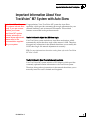
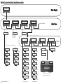
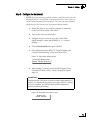
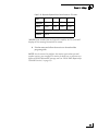
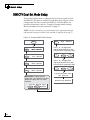
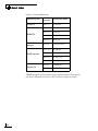
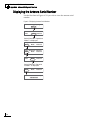
TracVision M5/M7
TracVision M5/M7
Control Panel Configuration
quick reference guide
flip here to view
User’s Guide
TracVision MultiSat Control Panel Menu
TracVision M7 with Auto Skew
Important Information About Your System
Important Information About Your
TracVision M7 System with Auto Skew
®
Note: Not all TracVison
M7 systems include Auto
Skew. If you are unsure
whether your linear
TracVision M7 system
includes automatic or
manual skew adjustment,
please refer to the
documentation supplied
with your system.
Congratulations! Your TracVision M7 system has Auto Skew
capability, which provides automatic skew angle adjustment for your
selected satellite(s), and an internal GPS antenna. These added
features are not cited in the product manuals.
You Do Not Need to Adjust the LNB Skew Angle.
Your TracVision system includes an Auto Skew mechanism, which
automatically adjusts the skew angle of the antenna’s LNB. Therefore,
disregard any instructions in the manuals that direct you to modify the
LNB’s skew angle. No manual adjustment is necessary.
TIP: For more information on how skew works, please refer to the TracVision
M7 User’s Guide.
You Do Not Need to Enter Your Latitude and Longitude.
Your TracVision M7 system includes a GPS antenna, which provides
constantly updated location information to the TracVision system.
Therefore, disregard any instructions in the manuals that direct you to
manually enter the vessel’s latitude and longitude.
54-0693 Rev. A
1
MultiSat Control Panel Menu Quick Reference Guide
Tracking <SAT NAME>
Menu
Install Satellite?
Yes
Next
Return
Circular or Linear?
Cir
Lin
Cancel
Set Sat Switch Type?
Yes
Next
Return
Auto or Manual?
Auto
Manual Cancel
Automatic
Satellite
Switching
Restart Antenna?
Yes
Next
Return
Select a DIRECTV
mode
Service=DISH?
Yes
Next Cancel
Select a DISH Network
mode
Service=ExpressVu?
Yes
Next Cancel
Select ExpressVu
Service=Custom?
Yes
Next Cancel
Select 1 or 2 satellites
from the library
Yes
Manual
Satellite
Switching
Trisat Mode?
No
Cancel
Get system errors?
Yes
Next Return
Select 1 or 2 satellites
from the library
Install Europe WB?
Yes
Next Cancel
Yes
Set sleep on/off?
Yes
Next Return
Get version?
Next Return
Set lat/long?
Yes
Next Return
Threshold and Signal Levels *
System halted
RF Flash Port
Main Flash Port
Set Latitude/Longitude
Sat frequency scan?
Yes
Next Return
Update Frequency Data ‡
LNB Skew Angle *
Get bit error rate?
Yes
Next Return
Configure satellite?
Yes
Next Return
Bit Error Rate *
Set Frequency, Symbol Rate,
FEC Code, and Network ID ‡
Get state?
Next Return
Reset to factory?
Yes
Next Return
Reset system to factory
default satellites/brightness ‡
Current State *
‡
TracVision M5/M7/M9 only
Return to
"Get Antenna
Status"
Max
Set Display Brightness
Set Instant On Mode On/Off
Get thres/sig level?
Yes
Next Return
* Press any button to return
Min
Bright
*************
Set instant on/off?
Yes
Next Return
Antenna Serial Number *
Yes
^RF
Use Jack Main^
HALT
Return
Set brightness?
Yes
Next
Return
Sleep Mode On/Off
Get serial number?
Yes
Next Return
Select Hotbird WB,
Sirius, Thor
Upgrade software?
Yes
Next
Return
Adjust Azimuth/Elevation
Antenna Software Versions *
Select Hotbird,
Astra1, Astra2S
Install Scandinavia?
Yes
Next Cancel
Man control antenna?
Yes
Next Return
Errors Detected *
Select Hotbird WB,
Astra1, Astra2S
Install Europe?
Yes
Next Cancel
Control antenna?
Yes
Next
Return
Get skew angle?
Yes
Next Return
2005-2008, KVH Industries, Inc.
Return to "Install Satellite"
Antenna restarted
Get antenna status?
Yes
Next
Return
Service=DIRECTV?
Yes
Next Cancel
Operations Mode?
Yes
Next
Return
Use the latest version of the KVH Flash
Update Wizard to upgrade the software
TracVision M5/M7 User’s Guide
TracVision M5/M7
MultiSat Control Panel Configuration
User’s Guide
This user’s guide provides all of the basic information you need to
operate, set up, and troubleshoot the TracVision M5/M7 satellite
TV antenna system. For detailed installation information, please
refer to the TracVision M5/M7 Installation Guide.
Please direct questions, comments, or suggestions to:
KVH Industries, Inc.
50 Enterprise Center
Middletown, RI 02842-5279 USA
Tel: +1 401 847-3327
Fax: +1 401 849-0045
E-mail: [email protected]
Internet: www.kvh.com
KVH Europe A/S
Kokkedal Industripark 2B
2980 Kokkedal, Denmark
Tel: +45 45 160 180
Fax: +45 45 160 181
E-mail: [email protected]
Internet: www.kvh.com
If you have any comments regarding this manual, please e-mail
them to [email protected]. Your input is greatly appreciated!
KVH Part # 54-0419-02 Rev. D
© 2007-2009, KVH Industries, Inc., All rights reserved.
U.S. Patents Pending
TracVision and KVH are registered trademarks of KVH Industries, Inc.
The unique light-colored dome with dark contrasting base is a registered trademark of KVH Industries, Inc.
DVB (Digital Video Broadcasting) is a registered trademark of the DVB Project.
DIRECTV is an official trademark of DIRECTV, Inc.
DISH Network is an official trademark of EchoStar Communications Corporation.
ExpressVu is a property of Bell ExpressVu, a wholly owned subsidiary of Bell Satellite Services.
All other trademarks are the property of their respective owners.
TracVision M5/M7 User’s Guide
Table of Contents
Table of Contents
1
Introduction
Using this Manual ..............................................................................3
System Overview...............................................................................5
Circular and Linear Versions..............................................................8
2
Operation
Receiving Satellite TV Signals .........................................................13
Turning the System On/Off ..............................................................14
Changing Channels and Switching Between Satellites
(Circular Versions) ...........................................................................15
Changing Channels and Switching Between Satellites
(Linear Versions)..............................................................................21
Receiver Requirements ...................................................................24
Product Care ....................................................................................26
3
Settings
Updating Latitude and Longitude Data ............................................29
Displaying the Calculated Skew Angle ............................................30
Adjusting the Skew Angle (Linear Versions)....................................31
Setting Sleep Mode .........................................................................35
Setting Instant On ............................................................................36
Adjusting Display Brightness...........................................................37
DISH Network/ExpressVu Setup ......................................................38
DIRECTV Dual-Sat Mode Setup ........................................................44
Circular Custom Dual-Sat Setup......................................................45
i
TracVision M5/M7 User’s Guide
Table of Contents
3
Settings (Continued)
European Tri-Sat Mode Setup..........................................................48
Linear Dual-Sat Mode Setup............................................................50
Selecting Automatic or Manual Satellite Switching.........................53
Resetting to Factory Default Settings ..............................................54
Restarting the TracVision System....................................................55
4
Troubleshooting
Five Simple Checks..........................................................................59
Troubleshooting Matrix ....................................................................60
Causes and Remedies for Operational Issues..................................61
Technical Support............................................................................65
A
Advanced Settings and Functions
Manually Controlling the Antenna....................................................69
Updating Satellite Frequency Data ..................................................70
Configuring Satellite Settings ..........................................................72
Displaying Software Version Information.........................................73
Displaying the Antenna Serial Number ............................................74
B
Position Grids
European Position Grid.....................................................................77
North American Position Grid...........................................................78
C
Wiring Diagrams
Wiring Diagram for One or Two Receivers.......................................81
Wiring Diagram for Three or Four Receivers
(Circular Versions)* ..........................................................................82
Wiring Diagram for Three or Four Receivers
(Linear Quad-output Versions) .........................................................83
ii
TracVision M5/M7 User’s Guide
Chapter 1 - Introduction
1. Introduction
This chapter provides a basic overview of this manual and your
TracVision system.
Contents
Using this Manual.............................................................. 3
System Overview............................................................... 5
Circular and Linear Versions.............................................. 8
1
TracVision M5/M7 User’s Guide
Chapter 1 - Introduction
Using this Manual
This manual provides complete operation, setup, and troubleshooting
information for your TracVision system, as well as wiring diagrams
for various TracVision M5/M7 system configurations.
Who Should Use This Manual
The user should refer to the “Operation” chapter to learn how to
operate the system.
The user, installer, or servicing technician should refer to the
“Settings” chapter for information on configuring the system and the
“Wiring Diagrams” appendix for information on connecting
additional receivers.
The user and/or servicing technician should refer to the
“Troubleshooting” chapter to help identify the cause of a system
problem.
Notifications Used in this Manual
This manual uses the following notifications to call attention to
important information:
CAUTION
This is a danger, warning, or caution notice. Be sure to read
these carefully to avoid injury!
IMPORTANT!
This is an important notice. Be sure to read these carefully to
ensure proper operation and configuration of your TracVision
system.
NOTE: Notes contain useful information about system settings.
TIP: Tips contain helpful information, allowing you to get the most out of
your TracVision system.
3
TracVision M5/M7 User’s Guide
Chapter 1 - Introduction
Typographical Conventions
This manual uses the following typographical conventions:
Text Example
Description
<SAT NAME>
###
Text in brackets or the pound sign (#) indicates a
variable portion of the MultiSat Control Panel
(MCP) display
MultiSat Control Panel (MCP) Interface Conventions
When instructions indicate to select a specific MCP menu option, press
the MCP button located directly beneath the menu option.
Figure 1-1 Example of MCP Menu Option and Corresponding Button
Tracking DISH 119
110
Menu
61
Related Documentation
In addition to this User’s Guide, the following documents are
provided with your TracVision system:
4
Document
Description
Installation Guide
Complete product installation
instructions
Product Registration Form
Details on registering the product
Warranty Statement
Warranty terms and conditions
Contents List
List of every part supplied in the kit
TracVision M5/M7 User’s Guide
Chapter 1 - Introduction
System Overview
Your TracVision M5/M7 system is a state-of-the-art, actively
stabilized antenna system that delivers live satellite TV to your
vessel’s audio/video entertainment system. A basic system is
illustrated below.
Figure 1-2 TracVision System Diagram (Typical Installation)
TracVision Antenna
Vessel Power
12 - 16 VDC
Switchplate
RF
Power
Data
Main Data
RF Data
Satellite Receiver(s)
TV(s)
Purchased Separately
MCP
TIP: Receiver wiring diagrams are provided in Appendix C on page 79.
5
TracVision M5/M7 User’s Guide
Chapter 1 - Introduction
System Components
The TracVision M5/M7 system includes the following components:
Antenna Unit
The antenna unit houses the antenna positioning
mechanism, LNB (low noise block), and control
elements within a radome. Weathertight
connectors join the power, signal, and control
cabling from the belowdecks units.
Switchplate
The switchplate controls power to the antenna via
the On/Off switch.
MCP (MultiSat Control Panel)
The MCP is the system’s user interface, providing
access to the system and its functions through an
LCD with three buttons. The MCP serves as the
system’s junction box, and allows you to configure
and operate the antenna.
6
MAINTENANCE
TracVision M5/M7 User’s Guide
Chapter 1 - Introduction
System Features
Your TracVision M5/M7 system uses integrated DVB technology to
quickly acquire and track the correct satellite, switch between your
selected satellites, and send TV signals to the receiver.
In-motion Tracking
The TracVision system uses a state-of-the-art actively stabilized
antenna. Once the satellite is acquired, the antenna’s internal gyros
and control system continuously measure the heading, pitch, and roll
of your vessel, keeping the antenna pointed at the satellite at all times even while you’re on the move!
Satellite Tracking and Switching
Your TracVision M5/M7 system tracks your selected satellites as long
as the vessel is located within the selected satellites’ coverage area.
During installation, your TracVision system should have been set up
to track your desired satellites, allowing you to switch between them
quickly and easily.
Satellite Library
The TracVision M5/M7 system includes a pre-programmed satellite
library of the most popular satellite services, offering a wide variety of
satellite services to choose from. For complete information on the
satellite library, see Chapter 3 ”Settings” on page 27.
TIP: You can add two more satellites of your choice to the satellite library. For
complete information on adding satellites to the library, refer to the associated
Application Note on the KVH Partner Portal (KVH-authorized technicians
only).
7
TracVision M5/M7 User’s Guide
Chapter 1 - Introduction
Circular and Linear Versions
Your TracVision system is configured to receive either circularly
polarized satellite signals (e.g., North America) or linearly polarized
satellite signals (e.g., Europe or Latin America). Figure 1-3 illustrates
the difference between these two polarizations.
Figure 1-3 Polarizations of Satellite Signals
Circular
Linear
Signals transmitted in two
“corkscrew” patterns, one
running clockwise and one
running counter-clockwise
Signals transmitted in vertical
and horizontal “waves” offset
exactly 90º from each other
LNB Skew Angle
Since linear satellite signals are oriented in a precise cross pattern, the
TracVision antenna’s receiving element, called an LNB (low-noise
block), must be oriented in the same way to optimize reception. This
orientation adjustment is referred to as the LNB’s “skew angle.”
Figure 1-4 illustrates how skew determines the amount of a linear
signal that the LNB collects. The more signal, the better the reception.
Figure 1-4 How Skew Works
Bad Skew
Good Skew
= Satellite Signal
8
Ideal Skew
= LNB "Signal Collector"
TracVision M5/M7 User’s Guide
Chapter 1 - Introduction
The correct skew setting varies depending on your geographic
location, since the orientation of your antenna to the satellite changes
as you move. For example, if your antenna is tracking the PAS 9
satellite for Sky Mexico programming, the ideal skew setting ranges
from +30 to +70, depending upon your location within the satellite’s
coverage area (see Figure 1-5).
Figure 1-5 Approximate Skew Settings for the PAS 9 Satellite
+50
+45
+40
+35 +30
+55
+60
+65
+70
For complete details about adjusting the LNB’s skew, see “Adjusting
the Skew Angle (Linear Versions)” on page 31.
9
TracVision M5/M7 User’s Guide
Chapter 2 - Operation
2. Operation
This chapter explains everything you need to know to operate the
TracVision system.
Contents
Receiving Satellite TV Signals ......................................... 13
Turning the System On/Off .............................................. 14
Changing Channels and Switching Between
Satellites (Circular Versions) ........................................... 15
Changing Channels and Switching Between
Satellites (Linear Versions).............................................. 21
Receiver Requirements ................................................... 24
Product Care.................................................................... 26
11
TracVision M5/M7 User’s Guide
Chapter 2 - Operation
Receiving Satellite TV Signals
Television satellites are located in fixed positions above the Earth’s
equator and beam TV signals down to certain regions of the planet
(not worldwide). To receive TV signals from a satellite, you must be
located within that satellite’s unique coverage area.
TIP: For your convenience, KVH provides links to several websites that offer
satellite coverage information. Simply visit our website at www.kvh.com/
footprint.
Figure 2-1 Location and Coverage Area of DIRECTV 101 Satellite
Equator
In addition, since TV satellites are located above the equator, the
TracVision antenna must have a clear view of the sky to receive
satellite TV signals. Anything that stands between the antenna and the
satellite can block the signal, resulting in lost reception. Common
causes of blockage include boat masts, trees, buildings, and bridges.
Heavy rain, ice, or snow might also temporarily interrupt satellite
signals.
Figure 2-2 Example of Satellite Blockage
Blocked!
TracVision
13
TracVision M5/M7 User’s Guide
Chapter 2 - Operation
Turning the System On/Off
You can turn the system on or off using the switchplate.
Turning On the System
Follow the steps below to turn on your TracVision system.
IMPORTANT!
Avoid turning the vessel or changing channels for one minute
after turning on the system.
1. Make sure the antenna has a clear view of the sky.
2. Turn on your satellite TV receiver and TV.
3. Set the switchplate’s Power switch to the On (|)
position.
Figure 2-3 Switchplate Power Switch
ON
OFF
MAINTENANCE
4. Wait one minute for system startup.
Turning Off the System
Follow the steps below to turn off your TracVision system.
1. Set the switchplate’s Power switch to the Off (O)
position.
2. Turn off your satellite TV receiver and TV.
14
TracVision M5/M7 User’s Guide
Chapter 2 - Operation
Changing Channels and Switching Between Satellites
(Circular Versions)
During installation, your TracVision system should have been set up
to track the satellite(s) of your choice and the channel guides for your
selected satellite service should have been downloaded.
Since some channels might be located on another satellite, changing
channels might require switching between satellites. With most
TracVision configurations, satellite switching occurs automatically
while you change channels using the primary receiver’s remote
control. Find your selected service and configuration in the following
sections for complete details.
TIP: The primary receiver is the receiver connected to the antenna’s RF1
connector.
DISH 1000 (Required for TurboHD Service)
When the TracVision M5/M7 system is configured for DISH 1000, you
can view the DISH HDTV programming for your geographic area. The
system can be configured for either DISH 1000/61 or DISH 1000/129
use.
Figure 2-4 DISH 1000 Configurations
Configuration
Satellites Tracked
DISH 1000/61
DISH 110, 119, and 61
DISH 1000/129
DISH 110, 119, and 129
During installation, your TracVision system should have been set to
the DISH 1000 configuration that best suits your geographic location
(see Figure 2-5) and local channels requirements. If you change
satellite coverage areas, refer to “DISH Network/ExpressVu Setup”
on page 38 to change your DISH 1000 configuration.
Figure 2-5 Regional DISH 1000 Configuration Recommendations
= DISH 129 Satellite Recommended
= DISH 61 Satellite Recommended
15
TracVision M5/M7 User’s Guide
Chapter 2 - Operation
DISH 1000 Automatic Mode - Preferred for One or Two Receivers
The antenna switches between satellites automatically as you change
channels using the primary receiver’s remote control. The primary
receiver is the receiver connected to RF1 (see Figure 2-6 and
Figure 2-7). If an optional secondary receiver is connected, you can use
its remote control to switch between the channels on the currently
selected satellite.
Figure 2-6 DISH 1000 Automatic Mode - Receiver Controls
Antenna
RF2
MCP
Switchplate
RF1
Grounding
Block
Primary Receiver
RF1
RF2
Automatically
switches
satellites/channels
Secondary
Receiver
(optional)
Changes
channels on
current satellite
Figure 2-7 DISH 1000 Automatic Mode - MCP Displays
DISH 1000/61
Tracking DISH 119
110
Menu
61
OR
Available Satellites
(Buttons Not Used)
Satellite Being
Tracked
16
DISH 1000/129
Tracking DISH 119
110
Menu
129
Available Satellites
(Buttons Not Used)
Satellite Being
Tracked
TracVision M5/M7 User’s Guide
Chapter 2 - Operation
DISH 1000 Manual Mode - Required for Three or More Receivers
Since multiswitches interfere with communications between the
receivers and the antenna, the system must be set up in Manual mode
when three or more receivers are installed. When Manual mode is
enabled, you can switch between your selected satellites using the
buttons on the front of the MCP (see Figure 2-8 and Figure 2-9). You
can use the receivers’ remote controls to switch between the channels
on the currently selected satellite.
Figure 2-8 DISH 1000 Manual Mode - Receiver/MCP Controls
Antenna
RF2
Switchplate
MCP
RF1
Buttons used
to switch satellites
Grounding
Block
All Receivers
Multiswitch
Changes
channels on
current satellite
Figure 2-9 DISH 1000 Manual Mode - MCP Displays
DISH 1000/61
Tracking DISH 119
110
Menu
61
Press
for 110
OR
Press
for 61
Satellite Being
Tracked
DISH 1000/129
Tracking DISH 119
110
Menu
129
Press
for 110
Press
for 129
Satellite Being
Tracked
17
TracVision M5/M7 User’s Guide
Chapter 2 - Operation
Dual-Sat Mode - Required for all DISH 500, ExpressVu, DIRECTV, and Custom
Dual-Sat Setups
Dual-Sat Mode is used with several service configurations. Figure 2-10
lists each Dual-Sat service configuration, the satellites tracked for each
service, and available satellite switching modes.
Figure 2-10 Dual-Sat Modes
18
Service
Satellites Tracked
Available
Switching Mode(s)
DIRECTV
DIRECTV 101 and 119
Auto or Manual
DISH 500
DISH 119 and 110
Auto or Manual
ExpressVu
ExpressVu 91 and 82
Auto or Manual
Custom
Selected by user
Manual
TracVision M5/M7 User’s Guide
Chapter 2 - Operation
Dual-Sat Automatic Mode - Preferred Mode for One or Two Receivers*
The antenna switches between satellites automatically while you
change channels using the primary receiver’s remote control. The
primary receiver is the receiver connected to the antenna’s RF1 cable
(see Figure 2-11 and Figure 2-12). If an optional secondary receiver is
connected, you can use its remote control to switch between the
channels on the currently selected satellite.
*NOTE: Custom Dual-Sat configurations must use Manual mode.
Figure 2-11 Dual-Sat Automatic Mode - Receiver Controls
Antenna
RF2
Switchplate
RF1
Grounding
Block
RF2
MCP
Primary Receiver
RF1
Secondary
Receiver
(optional)
Automatically
switches
satellites/channels
Changes
channels on
current satellite
Figure 2-12 Dual-Sat Automatic Mode - MCP Display
Tracking <Sat A>
<Sat B> Menu
Available Satellite
(Button Not Used)
Satellite Being
Tracked
19
TracVision M5/M7 User’s Guide
Chapter 2 - Operation
Dual-Sat Manual Mode - Required for Three or More Receivers and All
Custom Dual-Sat Setups
Circular TracVision M5/M7 systems with three or more receivers
require the use of a multiswitch. Since multiswitches interfere with
communications between the receivers and the antenna, the system
must be set up in Manual mode. When manual mode is enabled, you
can use the receiver’s remote control to change channels on the
currently selected satellite. If you need to switch satellites, simply use
the buttons on the front of the MCP (see Figure 2-13 and Figure 2-14).
You can use the receivers’ remote controls to switch between the
channels on the currently selected satellite.
Figure 2-13 Dual-Sat Manual Mode - Receiver/MCP Controls
Antenna
RF2
Switchplate
MCP
RF1
Grounding
Block
Buttons used
to switch satellites
All Receivers
Multiswitch
Changes
channels on
current satellite
Figure 2-14 Dual-Sat Manual Mode - MCP Display
Tracking <Sat A>
<Sat B> Menu
Press for
Sat B
Satellite Being
Tracked
20
TracVision M5/M7 User’s Guide
Chapter 2 - Operation
Changing Channels and Switching Between Satellites
(Linear Versions)
During installation, your TracVision system should have been set up
to track the satellite(s) of your choice and the channel guides for your
selected satellite service should have been downloaded.
Since some channels might be located on another satellite, changing
channels might require switching between satellites. Switching
satellites occurs automatically with most TracVision system
configurations. However, if the TracVision system includes a
multiswitch, manual satellite switching is required.
NOTE: To enable automatic switching, the receiver must be properly
configured (see “Linear Receiver Configuration” on page 25 for more
information).
21
TracVision M5/M7 User’s Guide
Chapter 2 - Operation
Automatic Satellite Switching
The TracVision system can switch between satellites automatically as
long as the primary receiver is set up for DiSEqC communicatons and
a multiswitch is not installed. With DiSEqC set up, the primary
receiver sends satellite switching commands to the antenna as
necessary when you change channels using the primary receiver’s
remote control. The primary receiver is the receiver connected to the
antenna’s RF1 cable (see Figure 2-15). If an optional secondary receiver
is connected, you can use its remote control to switch between the
channels on the currently selected satellite.
Figure 2-15 Primary/Secondary Receiver Control (Dual-output version shown)
Antenna
RF2
Switchplate
MCP
RF1
Grounding
Block
RF2
Primary Receiver
RF1
Secondary
Receiver
(optional)
Automatically
switches
satellites/channels
Changes
channels on
current satellite
Figure 2-16 Automatically Switching Between Satellites - MCP Displays
Three Satellites Installed
Tracking <Sat A>
<Sat B> Menu <Sat C>
Available Satellites
(Buttons Not Used)
Satellite Being
Tracked
22
OR
Two Satellites Installed
Tracking <Sat A>
<Sat B> Menu
Available Satellite
(Button Not Used)
Satellite Being
Tracked
TracVision M5/M7 User’s Guide
Chapter 2 - Operation
Manual Satellite Switching
If the TracVision system includes a multiswitch, you can use the
receivers’ remote controls to change channels on the currently selected
satellite. If you need to switch satellites, simply use the buttons on the
front of the MCP (see Figure 2-17 and Figure 2-18).
Figure 2-17 Manual Satellite Switching - Receiver/MCP Controls (Quad-output version
shown)
Antenna
Switchplate
MCP
Buttons used
to switch satellites
Multiswitch
All Receivers
Changes
channels on
current satellite
Figure 2-18 Manually Switching Between Satellites - MCP Displays
Three Satellites Installed
Tracking <Sat A>
<Sat B> Menu <Sat C>
Press
for Sat B
Press
for Sat C
Satellite Being
Tracked
OR
Two Satellites Installed
Tracking <Sat A>
<Sat B> Menu
Press
for Sat B
Satellite Being
Tracked
23
TracVision M5/M7 User’s Guide
Chapter 2 - Operation
Receiver Requirements
This section lists U.S. and Canadian circular receiver models that are
compatible with the TracVision M5/M7 system and explains linear
and circular receiver setup requirements.
Circular Receiver Compatibility
To ensure compatibility with your TracVision M5/M7 system, be sure
to use a KVH-validated receiver for your selected service type (see
Figure 2-19).
Figure 2-19 KVH-Validated U.S. and Canadian Receivers
Standard-definition receivers
DIRECTV
DISH
ExpressVu
D12
311
4100
D11
3100
D10
High-definition receivers
DIRECTV
DISH
ExpressVu
HD not
supported
211k
6100
211
NOTE: For information on connecting different receiver models, contact
KVH Technical Support at 1-401-847-3327.
24
TracVision M5/M7 User’s Guide
Chapter 2 - Operation
DISH Network/ExpressVu Receiver Configuration
If your TracVision M5/M7 system is set up for DISH Network or
ExpressVu service, your receiver(s) should have also been configured
during installation. In most cases, you do not need to reconfigure your
receiver(s). However, Figure 2-20 lists special scenarios that require
DISH Network/ExpressVu receiver configuration.
Figure 2-20 Receiver Configuration Requirements
Receiver Configuration is Required When...
•
DISH 1000 only - You change satellite coverage
areas (see Figure 2-5 on page 15)
•
You add a receiver
•
You have reconfigured a receiver for home use
If you need to configure a receiver(s) for DISH Network/ExpressVu
use, follow the instructions for configuring the receiver for your
selected service type in Chapter 3 ”Settings” on page 27.
Linear Receiver Configuration
If the TracVision system does not include a multiswitch, you can
configure the receiver(s) to enable automatic satellite switching.
TracVision systems with a multiswitch installed require switching
satellites using the MCP, which does not require receiver
configuration.
To configure the receivers for automatic switching, the satellites must
be set up in the receiver in the same order they were set up in the
TracVision system (see Figure 2-21).
Figure 2-21 Antenna/Receiver Synchronization Settings
TracVision Satellite
Receiver Satellite
DiSEqC Setting
Satellite A
Alternative 1 or A
DiSEqC 1
Satellite B
Alternative 2 or B
DiSEqC 2
Satellite C*
Alternative 3 or C
DiSEqC 3
*NOTE: Only European Tri-Sat configurations track three satellites.
25
TracVision M5/M7 User’s Guide
Chapter 2 - Operation
Product Care
Please consider the following antenna care guidelines for maintaining
peak performance:
26
•
Periodically wash the exterior of the antenna dome with fresh
water and mild detergent. Avoid harsh cleansers and volatile
solvents (such as acetone) and do not spray the dome directly with
high-pressure water.
•
If you wish to paint the dome, use only non-metallic automotive
paint without a primer coat. Any paint that contains metal will
block satellite signals and impair reception.
TracVision M5/M7 User’s Guide
Chapter 3 - Settings
3. Settings
This chapter contains information on system settings and how to modify
them.
Contents
Updating Latitude and Longitude Data ............................ 29
Displaying the Calculated Skew Angle ............................ 30
Adjusting the Skew Angle (Linear Versions).................... 31
Setting Sleep Mode ......................................................... 35
Setting Instant On............................................................ 36
Adjusting Display Brightness........................................... 37
DISH Network/ExpressVu Setup ...................................... 38
DIRECTV Dual-Sat Mode Setup........................................ 44
Circular Custom Dual-Sat Setup ..................................... 45
European Tri-Sat Mode Setup ......................................... 48
Linear Dual-Sat Mode Setup............................................ 50
Setting Manual or Automatic Switching .......................... 53
Resetting to Factory Default Settings.............................. 54
Restarting the TracVision System ................................... 55
27
TracVision M5/M7 User’s Guide
Chapter 3 - Settings
Updating Latitude and Longitude Data
Use the flowchart in Figure 3-1 if you wish to update your latitude and
longitude data.
TIP: For your convenience, you can determine your approximate latitude and
longitude using the Position Grids provided in Appendix B on page 75.
Figure 3-1 Updating Latitude and Longitude Data
<Default Display>
Menu
Install Satellite?
Yes
Next Return
Select Next until “Operations
Mode?” is displayed.
Operations Mode?
Yes
Next Return
Get Antenna Status?
Yes
Next Return
Control Antenna?
Yes
Next Return
Man Control Antenna?
Yes
Next Return
Select Next Until “Set
Lat/Long?” is displayed.
Yes
Set Lat/Long?
Next Return
Press - or + to toggle each
digit to the desired value, then
press Enter to accept each digit.
Latitude:
Enter
##N
+
Press - or + to toggle each
digit to the desired value, then
press Enter to accept each digit.
Longitude:
###E
Enter
+
Restarting Antenna
29
TracVision M5/M7 User’s Guide
Chapter 3 - Settings
Displaying the Calculated Skew Angle
Use the flowchart in Figure 3-2 to display the average skew angle for
your selected satellites. If just one satellite is configured for tracking,
that satellite’s skew angle is displayed.
IMPORTANT!
An accurate skew angle reading requires current latitude and
longitude data. If necessary, be sure to update the latitude and
longitude data before proceeding (see “Updating Latitude and
Longitude Data” on page 29 for more information).
Figure 3-2 Displaying the Calculated Skew Angle
<Default Display>
Menu
Install Satellite?
Yes
Next Return
Select Next until “Operations
Mode?” is displayed.
Operations Mode?
Yes
Next Return
Get Antenna Status?
Yes
Next Return
Get system errors?
Yes
Next Return
Select Next until “Get skew
angle?” is displayed.
Get skew angle?
Yes
Next Return
Skew Angle
OK
30
##.#
TracVision M5/M7 User’s Guide
Chapter 3 - Settings
Adjusting the Skew Angle (Linear Versions)
Once you have determined the proper skew angle, follow the steps
below to adjust the antenna’s LNB skew angle.
TIP: Refer to “Displaying the Calculated Skew Angle” on page 30 to
determine the skew angle for the currently selected satellite. If you wish to
determine the average skew angle for two or three satellites, see “European
Tri-Sat Mode Setup” on page 48 or “Linear Dual-Sat Mode Setup” on
page 50.
TIP: For information on how skew works, see “LNB Skew Angle” on
page 8.
CAUTION
To avoid bodily injury, be sure to turn off the antenna and
disconnect power to all wired components.
1. Using a Phillips-head screwdriver, remove the screws
securing the radome. Then remove the radome and set
it aside in a safe place.
2. Locate the LNB assembly on the back of the antenna
reflector.
Figure 3-3 Location of LNB on Back of Antenna Reflector
Reflector
LNB
Assembly
31
TracVision M5/M7 User’s Guide
Chapter 3 - Settings
3. Using a 2 mm allen hex key, loosen the two M4 socket
set screws securing the LNB. The location of the screws
varies according to TracVision model; refer to
Figure 3-4 or Figure 3-5.
Figure 3-4 TracVision M5 Set Screws
Reflector
M4 Socket
Set Screws
Figure 3-5 TracVision M7 Set Screws
M4 Socket
Set Screws
Reflector
LNB
32
TracVision M5/M7 User’s Guide
Chapter 3 - Settings
4a. TracVision M5 Only - Adjust the LNB clockwise or
counter-clockwise, until the skew arrow on the LNB
points to the skew angle that you determined earlier.
Due to label constraints, if the skew angle is greater
than +15°, you need to subtract 180 to get the
equivalent negative skew angle and set the LNB to that
angle instead. For example, if the skew angle is
determined to be +30°, set the skew to -150°.
IMPORTANT!
Be sure to keep the LNB fully inserted in the choke feed to
ensure optimum performance.
Figure 3-6 TracVision M5 LNB Skew Angle Adjustment
LNB
SKEW
Choke Feed
Negative
Skews
0 Skew
Positive
Skews
33
TracVision M5/M7 User’s Guide
Chapter 3 - Settings
4b. TracVision M7 Only - Adjust the LNB clockwise or
counter-clockwise, until the skew arrow on the LNB
points to the skew angle that you determined earlier.
IMPORTANT!
Be sure to keep the LNB fully inserted in the choke feed to
ensure optimum performance.
Figure 3-7 TracVision M7 LNB Skew Angle Adjustment
LNB
Choke Feed
60
0
07 5
90 8 75 6
85
55 60
65 70 80
90
75
85
SKEW
55
50
0
4
05
45 0 30
0 4 45
0
3
2
0
0
2
10
10
35
35
25
15 5 5 15 25
Negative
Skews
0˚ Skew
Positive
Skews
5. Tighten the two M4 socket set screws to secure the LNB
in place. Apply 9 in-lbs (1 Nm) of torque, if possible.
6. Reinstall the radome.
7. Restore power to the TracVision system.
34
TracVision M5/M7 User’s Guide
Chapter 3 - Settings
Setting Sleep Mode
When the vessel has come to a stop and holds its position for one
minute (e.g., at a dock), the antenna unit enters Sleep Mode, which
locks the antenna in place to conserve power. As soon as the vessel
moves beyond a 1° - 2° window or the signal level changes
significantly, Sleep Mode automatically turns off and the system
begins tracking the satellite again (or enters Search Mode to find the
satellite).
Use the flowchart in Figure 3-8 if you wish to disable Sleep Mode, or if
you wish to restore the original Sleep Mode setting.
Figure 3-8 Setting Sleep Mode On/Off
<Default Display>
Menu
Install Satellite?
Yes
Next Return
Select Next until “Operations
Mode?” is displayed.
Operations Mode?
Yes
Next Return
Get Antenna Status?
Yes
Next Return
Control Antenna?
Yes
Next Return
Man Control Antenna?
Yes
Next Return
Set Sleep on/off?
Yes
Next Return
On
Sleep Mode: ON
Enter
Off
Select On or Off as required,
then select Enter.
35
TracVision M5/M7 User’s Guide
Chapter 3 - Settings
Setting Instant On
When Instant On is enabled, the antenna can immediately receive
signals if the vessel has not moved since the antenna was last shut off.
However, if the system is turned off, and then the vessel moves after
last acquiring the satellite via Instant On, the antenna will undergo its
standard initialization process once it is turned back on. This results in
a brief delay.
NOTE: Instant On is disabled by default and is not recommended for DISH
Network and ExpressVu configurations.
Use the flowchart in Figure 3-9 if you wish to enable Instant On, or if
you wish to restore the original setting.
Figure 3-9 Enabling/Disabling Instant On
<Default Display>
Menu
Install Satellite?
Yes
Next Return
Select Next until “Operations
Mode?” is displayed.
Operations Mode?
Yes
Next Return
Get Antenna Status?
Yes
Next Return
Control Antenna?
Yes
Next Return
Select Next until “Set instant
on/off?” is displayed.
Set instant on/off?
Yes
Next Return
instant mode: ON
On
Enter
Off
Select On or Off as required,
then select Enter.
36
TracVision M5/M7 User’s Guide
Chapter 3 - Settings
Adjusting Display Brightness
You can adjust the brightness of the MCP’s LCD screen to suit your
preferences. Use the flowchart in Figure 3-10 if you wish to adjust the
display brightness.
Figure 3-10 Setting Display Brightness
<Default Display>
Menu
Install Satellite?
Yes
Next Return
Select Next until “Operations
Mode?” is displayed.
Operations Mode?
Yes
Next Return
Get Antenna Status?
Yes
Next Return
Select Next until “Set
Brightness?” is displayed.
Set Brightness?
Yes
Next Return
Min
Bright
**********
Press to
Dim
Press to
Accept
Max
Press to
Brighten
37
TracVision M5/M7 User’s Guide
Chapter 3 - Settings
DISH Network/ExpressVu Setup
This section explains how to configure the TracVision system for
DISH 1000, DISH 500, or ExpressVu use. For operation instructions
and additional information on DISH modes, refer to “Changing
Channels and Switching Between Satellites (Circular Versions)” on
page 15.
Step 1 - Configure the TracVision System
Use the flowchart in Figure 3-11 on page 39 to configure the
TracVision system for DISH Network service. If you need to configure
the system for ExpressVu service, see Figure 3-12 on page 40.
IMPORTANT!
This procedure must be performed while the vessel is docked in
calm water.
NOTE: For your convenience, you can determine your approximate latitude
and longitude using the Position Grids provided in Appendix B on page 75.
38
TracVision M5/M7 User’s Guide
Chapter 3 - Settings
Figure 3-11 Configuring DISH Network
<Default Display>
Menu
Install Satellite?
Yes
Next Return
Circular or Linear?
Cir
Lin Return
Service= DIRECTV?
Yes
Next Cancel
Service= DISH?
Yes
Next Cancel
Mode= DISH 1000/61?
Yes
Next Cancel
Yes
Set Lat/Long?
Next Return
Press - or + to toggle each
digit to the desired value, then
press Enter to accept each digit.
Latitude:
Enter
##N
+
Press - or + to toggle each
digit to the desired value, then
press Enter to accept each digit.
Longitude:
###E
Enter
+
Installing DISH sats
Restarting Antenna
Press Next until your desired
DISH mode is displayed, then
press Next.
Please Run
Check Switch
Mode= DISH 1000/129?
Yes
Next Cancel
Mode= DISH 500?
Yes
Next Cancel
IMPORTANT: Choose Auto for
configurations if 1 or 2 receivers are
connected; choose Manual if 3 or
more receivers are connected.
Set Sat Switch Type
Auto
Manual Cancel
39
TracVision M5/M7 User’s Guide
Chapter 3 - Settings
Figure 3-12 Configuring ExpressVu
<Default Display>
Menu
Install Satellite?
Yes
Next Return
IMPORTANT: Choose Auto for
configurations if 1 or 2 receivers are
connected; choose Manual if 3 or
more receivers are connected.
Set Sat Switch Type
Auto
Manual Cancel
Circular or Linear?
Cir
Lin Return
Yes
Set Lat/Long?
Next Return
Service= DIRECTV?
Yes
Next Cancel
Service= DISH?
Yes
Next Cancel
Service= ExpressVu?
Yes
Next Cancel
Press - or + to toggle each
digit to the desired value, then
press Enter to accept each digit.
Latitude:
Enter
##N
+
Press - or + to toggle each
digit to the desired value, then
press Enter to accept each digit.
Longitude:
###E
Enter
+
Installing EXVU sats
91 and 82
Restarting Antenna
Please Run
Check Switch
40
TracVision M5/M7 User’s Guide
Chapter 3 - Settings
Step 2 - Configure the Receiver(s)
NOTE: If you are connecting multiple receivers, repeat this process for each
additional receiver. You will need to connect each receiver, one at a time, to
the RF1 cable and perform the steps below. Then, once you have completed
this process for each receiver, you can reconnect them as desired.
1. Ensure the receiver you wish to configure is connected
to the TracVision system’s RF1 cable.
2. Turn on the TV(s) and receiver(s).
3. Using the receiver’s remote, go to the “Point Dish/
Signal Strength” screen (press MENU, 6, 1, 1 on most
models).
4. Choose Check Switch, then press SELECT.
5. Choose Test, then press SELECT. The MCP displays the
“Check Switch Running” screen (see Figure 3-13).
Figure 3-13 Check Switch Running Screen
Finding Satellites
Check Switch Running
6. After waiting 15 minutes, check the MCP display. If the
“Please Run Check Switch” screen is displayed, repeat
Steps 3-5.
IMPORTANT!
Please be patient. The Check Switch test takes approximately 15
minutes to complete. Disregard any messages on the TV stating
the test is complete; the antenna must perform additional
operations before proceeding.
Figure 3-14 Please Run Check Switch Screen
Please Run
Check Switch
41
TracVision M5/M7 User’s Guide
Chapter 3 - Settings
7. Refer to the tables in Figures 3-15 through
Figure 3-18 (on the following page) to verify the values
on your TV screen match those required for your
selected satellite TV service. If your values do not
match, turn off the TracVision system, then turn it back
on and repeat Steps 3-6.
Figure 3-15 DISH 1000/61 Expected Check Switch Results on TV Screen
Port
1
2
3
Satellite
119
110
61
Trans
OK
OK
OK
Status
Reception Verified
Switch
SW64
Figure 3-16 DISH 1000/129 Expected Check Switch Results on TV Screen
Port
1
2
3
Satellite
119
110
129
Trans
OK
OK
OK
Status
Reception Verified
Switch
SW64
Figure 3-17 DISH 500 Expected Check Switch Results on TV Screen
42
Port
1
1
2
2
Satellite
119
119
110
110
Trans
Odd
Even
Odd
Even
Status
Reception Verified
Switch
SW42
TracVision M5/M7 User’s Guide
Chapter 3 - Settings
Figure 3-18 ExpressVu Expected Check Switch Results on TV Screen*
Port
1
1
2
2
Satellite
91
91
82
82
Trans
Odd
Even
Odd
Even
Status
Reception Verified
Switch
SW21
*NOTE: If you installed just one ExpressVu satellite, the TV screen will
display an error message instead; this is normal.
8. Exit the menu and allow the receiver to download the
program guide.
NOTE: You do not need to configure the receiver again unless you add
another receiver, you reconfigure a receiver for home use, or you move to a
different DISH 1000 satellite coverage area (see “DISH 1000 (Required for
TurboHD Service)” on page 15).
43
TracVision M5/M7 User’s Guide
Chapter 3 - Settings
DIRECTV Dual-Sat Mode Setup
This section explains how to configure the TracVision system to track
the DIRECTV 101 and 119 satellites. Use the flowchart in Figure 3-19 to
configure the TracVision system for DIRECTV Dual-Sat Mode. For
operation instructions, refer to “Changing Channels and Switching
Between Satellites (Circular Versions)” on page 15.
NOTE: For your convenience, you can determine your approximate latitude
and longitude using the Position Grids provided in Appendix B on page 75.
Figure 3-19 Configuring DIRECTV Dual-Sat Mode
<Default Display>
Menu
Install Satellite?
Yes
Next Return
Circular or Linear?
Cir
Lin Cancel
Service= DIRECTV?
Yes
Next Cancel
Mode= Dual-Sat?
Yes
Next Cancel
IMPORTANT: Choose Auto for
setups with 1 or 2 receivers. Choose
Manual for setups with 3 or more
receivers.
Set Sat Switch Type
Auto
Manual Cancel
44
Yes
Set Lat/Long?
Next Return
Press - or + to toggle each
digit to the desired value, then
press Enter to accept each digit.
Latitude:
Enter
##N
+
Press - or + to toggle each
digit to the desired value, then
press Enter to accept each digit.
Longitude:
###E
Enter
+
Installing DTV sats
101 and 119
Restarting Antenna
TracVision M5/M7 User’s Guide
Chapter 3 - Settings
Circular Custom Dual-Sat Setup
The following instructions explain how to configure the TracVision
system to track any two satellites of your choice from the circular
antenna’s circular satellite library (shown in Figure 3-20 on page 46).
For operation instructions, refer to “Changing Channels and
Switching Between Satellites (Circular Versions)” on page 15.
IMPORTANT!
Most DIRECTV, DISH Network, and ExpressVu subscribers
should refer to the previous sections for setup information. The
TracVision system should only be configured for Custom DualSat Mode if you wish to install just one satellite or install
different satellites than those specified for your satellite service.
Refer to “DISH Network/ExpressVu Setup” on page 38 or
“DIRECTV Dual-Sat Mode Setup” on page 44 for more
information.
NOTE: Be sure to only install satellites that your TracVision M5/M7 system
can track in your geographic location. For your convenience, KVH provides
links to several websites that offer satellite coverage information. Simply visit
our website at www.kvh.com/footprint.
45
TracVision M5/M7 User’s Guide
Chapter 3 - Settings
Figure 3-20 Circular Satellite Library
Satellite Service
Satellite
Location
Installation Name
AsiaSat 4
122.2° E
ASIASAT*
72.0° W
DSS_72
101.0° W
DSS_101
110.0° W
DSS_110*
119.0° W
DSS_119
95.0° W
GALAXY3CN*
61.5° W
ECHO_61
110.0° W
ECHO_110
119.0° W
ECHO_119
129.0° W
ECHO_129
91.0° W
EXPRESSTV
82.0° W
EXPRESSVU
DIRECTV
DIRECTV Latin
America
DISH Network
ExpressVu
*NOTE: Reception of these satellites requires special hardware. Please contact
your local KVH-authorized dealer or KVH Technical Support for details.
46
TracVision M5/M7 User’s Guide
Chapter 3 - Settings
Use the flowchart in Figure 3-21 to configure the TracVision system for
your custom pair of satellites (or single satellite).
Figure 3-21 Configuring Custom Dual-Sat Mode
<Default Display>
Menu
Install <SAT NAME>
Yes
Next Cancel
Press Next until your choice
for Satellite A is displayed,
then press Yes.
Install Satellite?
Yes
Next Return
Circular or Linear?
Cir
Lin Cancel
Install <SAT NAME>
Yes
Next Cancel
Press Next until your choice
for Satellite B is displayed, then
press Yes. (Choose “NONE” as
your choice for Satellite B if you
wish to install just one satellite.)
Service= DIRECTV?
Yes
Next Cancel
Press Next until
Service= Custom? is displayed.
Service= Custom?
Yes
Next Cancel
Manual Switching Only
Yes
Set Lat/Long?
Next Return
Press - or + to toggle each
digit to the desired value, then
press Enter to accept each digit.
Latitude:
Enter
##N
+
Press - or + to toggle each
digit to the desired value, then
press Enter to accept each digit.
Longitude:
###E
Enter
+
<SAT A> and
<SAT B> installed
Restarting Antenna
47
TracVision M5/M7 User’s Guide
Chapter 3 - Settings
European Tri-Sat Mode Setup
This section explains how to configure the TracVision system to track
three satellites within predefined linear satellite groups for use in
European locations (see Figure 3-22). For operation instructions, refer
to “Changing Channels and Switching Between Satellites (Linear
Versions)” on page 21.
Figure 3-22 European Tri-Sat Groups - Satellites/TracVision Position
Group Name
Europe WB
Europe
Scandinavia
Satellites
Position
Hotbird WB
A
Astra 1
B
Astra 2S
C
Hotbird
A
Astra 1
B
Astra 2S
C
Hotbird WB
A
Sirius
B
Thor
C
NOTE: To enable automatic switching, the receiver must be set up to match
the TracVision system’s satellite position settings (A, B, or C). Refer to
“Linear Receiver Configuration” on page 25 for more information.
Step 1 - Configure the European Tri-Sat Group
Use the flowchart in Figure 3-23 on page 49 if you need to configure
the TracVision system for European Tri-Sat Mode.
NOTE: Be sure to record the skew angle (the average skew for all three
satellites) that is displayed during this procedure. You will need this
information to adjust the TracVision system’s skew angle. See “Adjusting the
Skew Angle (Linear Versions)” on page 31 for more information on setting
the skew angle.
48
TracVision M5/M7 User’s Guide
Chapter 3 - Settings
Figure 3-23 Configuring European Tri-Sat Mode
<Default Display>
Menu
Install Satellite?
Yes
Next Return
Circular or Linear?
Cir
Lin Cancel
Trisat Mode?
Yes
No Cancel
Install Europe WB?
Yes
Next Cancel
Press Next until your desired
Trisat Group is displayed, then
press Yes.
Install Europe?
Yes
Next Cancel
Yes
Set Lat/Long?
Next Cancel
Latitude:
Enter
##N
+
Press - or + to toggle each
digit to the desired value, then
press Enter to accept each digit.
Longitude:
Enter
###E
+
Press - or + to toggle each
digit to the desired value, then
press Enter to accept each digit.
Latitude:
Longitude:
##N
###E
<SAT A>, <SAT B>,
and <SAT C> installed
Restarting Antenna
Install Scandinavia?
Yes
Next Cancel
IMPORTANT: Choose Auto if you
don’t have a multiswitch installed;
choose Manual if you do have a
multiswitch installed.
Record the skew angle for
later use, then press OK.
Skew Angle
OK
##.#
Set Sat Switch Type
Auto
Manual Cancel
Step 2 - Adjust the LNB Skew Angle
Now that you have installed the desired Tri-Sat group and recorded
the skew angle for the Tri-Sat group, you need to adjust the antenna’s
LNB skew angle to optimize signal reception. Follow the instructions
in “Adjusting the Skew Angle (Linear Versions)” on page 31 to adjust
the skew angle.
49
TracVision M5/M7 User’s Guide
Chapter 3 - Settings
Linear Dual-Sat Mode Setup
This section explains how to configure the TracVision system to track
any two satellites from the antenna’s linear satellite library (shown in
Figure 3-24). For operation instructions, refer to “Changing Channels
and Switching Between Satellites (Linear Versions)” on page 21.
Figure 3-24 Linear Satellite Library
Satellite
Location
Satellite
Installation Name
26.0° E
Arabsat
ARABSAT
19.2° E
Astra 1
ASTRA1
28.2° E
Astra 2N
ASTRA2N
28.2° E
Astra 2S
ASTRA2S
7.0° E
Eutelsat W3A
EUTEL_W3A
30.0° W
Hispasat
HISPASAT
13.0° E
Hotbird
HOTBIRD
13.0° E
Hotbird WB
HOTBIRDWB
7.0° W
Nilesat
NILESAT
160.0° E
Optus D1
OPTUSD1*
156.0° E
Optus C1
OPTUSC1
58.0°W
Pas 9
PAS_9
110.5° E
Sinosat 1
SINOSAT*
5.0° E
Sirius
SIRIUS
0.8° W
Thor
THOR
42.0° E
Turksat 1C
TURKSAT1C
*NOTE: Reception of these satellites requires special hardware. Please contact
your local KVH-authorized dealer/distributor or KVH Technical Support for
details.
50
TracVision M5/M7 User’s Guide
Chapter 3 - Settings
Step 1 - Configure the Satellites
Use the flowchart in Figure 3-25 to configure the TracVision system for
linear Dual-Sat Mode.
NOTE: Be sure to record the skew angle (the average skew for both satellites)
reported during this procedure. You will need this information to adjust the
TracVision system’s skew angle.
Figure 3-25 Configuring Linear Dual-Sat Mode
<Default Display>
Menu
Install Satellite?
Yes
Next Return
Circular or Linear?
Cir
Lin Cancel
Trisat Mode?
Yes
No Cancel
Install <SAT NAME>
Yes
Next Cancel
Press Next until your choice
for Satellite A is displayed,
then press Yes.
Install <SAT NAME>
Yes
Next Cancel
Yes
Set Lat/Long?
Next Cancel
Latitude:
Enter
##N
+
Press - or + to toggle each
digit to the desired value, then
press Enter to accept each digit.
Longitude:
Enter
###E
+
Press - or + to toggle each
digit to the desired value, then
press Enter to accept each digit.
Latitude:
Longitude:
##N
###E
<SAT A>, and
<SAT B> installed
Restarting Antenna
Press Next until your choice
for Satellite B is displayed, then
press Yes. (Choose “NONE” as
your choice for Satellite B if you
wish to install just one satellite.)
IMPORTANT: Choose Auto for
setups without a multiswitch installed;
choose Manual for setups with a
multiswitch installed.
Record the skew angle for
later use, then press OK.
Skew Angle
OK
##.#
Set Sat Switch Type
Auto
Manual Cancel
51
TracVision M5/M7 User’s Guide
Chapter 3 - Settings
Step 2 - Adjust the LNB Skew Angle
Now that you have installed the desired satellites and recorded the
skew angle, you need to adjust the antenna’s LNB skew angle to
optimize signal reception. Follow the instructions in “Adjusting the
Skew Angle (Linear Versions)” on page 31 to adjust the skew angle.
NOTE: To enable automatic satellite switching, the receiver must be set up to
match the TracVision system’s satellite settings. Refer to “Linear Receiver
Configuration” on page 25 for more information.
52
TracVision M5/M7 User’s Guide
Chapter 3 - Settings
Selecting Automatic or Manual Satellite Switching
When your TracVision system was configured, the satellite switching
method (automatic or manual) was also selected. However, you can
use the flowchart in Figure 3-26 to change the satellite switching
method for your selected service, if desired.
NOTE: While most TracVision configurations support automatic switching,
Custom Dual-Sat configurations and any configurations with a multiswitch
installed require manual switching. For more information on satellite
switching options for your selected configuration, refer to the applicable
service setup instructions in this chapter.
Figure 3-26 Setting the Satellite Switching Method
<Default Display>
Menu
Install Satellite?
Yes
Next Return
Set Sat Switch Type?
Yes
Next Return
Sat Switch: Auto
Auto
Enter Manual
Choose your satellite
switching method, then
press Enter.
53
TracVision M5/M7 User’s Guide
Chapter 3 - Settings
Resetting to Factory Default Settings
Use the flowchart in Figure 3-27 if you wish to reset the TracVision
system to the factory default satellite service (DIRECTV Dual-Sat
Mode) and LCD brightness settings.
Figure 3-27 Resetting to Factory Default Settings
<Default Display>
Menu
Install Satellite?
Yes
Next Return
Select Next until “Operations
Mode?” is displayed.
Operations Mode?
Yes
Next Return
Get Antenna Status?
Yes
Next Return
Control Antenna?
Yes
Next Return
Select Next until “Reset to
Factory?” is displayed.
Reset to Factory?
Yes
Next Return
54
TracVision M5/M7 User’s Guide
Chapter 3 - Settings
Restarting the TracVision System
Use the flowchart in Figure 3-28 if you wish to restart the TracVision
system.
Figure 3-28 Restarting the TracVision System
<Default Display>
Menu
Install Satellite?
Yes
Next Return
Select Next until “Restart
Antenna?” is displayed.
Restart Antenna?
Yes
Next Return
Antenna Restarted
55
TracVision M5/M7 User’s Guide
Chapter 4 - Troubleshooting
4. Troubleshooting
This chapter identifies potential basic problems along with their possible
causes and solutions. It also explains how to get technical support.
Contents
Five Simple Checks ......................................................... 59
Troubleshooting Matrix.................................................... 60
Causes and Remedies for Operational Issues ................. 61
Technical Support............................................................ 65
57
TracVision M5/M7 User’s Guide
Chapter 4 - Troubleshooting
Five Simple Checks
If you are experiencing a problem receiving satellite TV with your
TracVision system, perform the five simple checks below.
TIP: You can also try resetting the satellite TV receiver. Turn off and unplug
the receiver, wait one minute, then plug it back in and turn it back on.
Can the antenna see the satellite?
The antenna requires an unobstructed view of the sky to receive
satellite TV signals. Common causes of blockage include trees,
buildings, bridges, and mountains.
Is there excessive dirt or moisture on the antenna dome?
Dirt buildup or moisture on the dome can reduce satellite reception.
Clean the exterior of the dome periodically.
Is it raining heavily?
Heavy rain or snow can weaken satellite TV signals. Reception should
improve once the inclement weather subsides.
Is everything turned on and connected properly?
Make sure your TV and receiver are both turned on and set up for the
satellite input. Finally, check any connecting cables to ensure none
have come loose.
(Linear Versions Only) Is the antenna’s LNB set to the correct skew angle?
To optimize reception, the antenna’s LNB needs to be set to the correct
skew angle for the satellite(s) you want to track. See “Adjusting the
Skew Angle (Linear Versions)” on page 31 for details.
59
TracVision M5/M7 User’s Guide
Chapter 4 - Troubleshooting
Troubleshooting Matrix
The troubleshooting matrix in Figure 4-1 identifies potential
operational symptoms and their causes and remedies. “Causes and
Remedies for Operational Issues” on page 61 contains detailed
information on the causes and remedies listed below.
r im
ult o
r fa
Sat
ellit
eive
Rec
SYMPTOM
CAU
SES
AN
DR
EM
EDI
ES
pro
e co
per
vera
Sat
rece
ge i
ellit
iver
ssu
e si
con
e
gna
figu
Rad
l
b
ratio
lock
ar in
ed
n
terf
ere
Sat
nce
ellit
e fr
equ
Ves
enc
sel
y da
turn
ta c
i
ng d
han
Insu
urin
ged
ffici
g st
ent
a
p
r
owe
tup
Imp
r
rop
er w
iring
Loo
se R
F co
nne
Typ
ctor
e of
s
mul
tisw
Cab
itch
le u
use
nwr
d
ap
Figure 4-1 Troubleshooting Matrix
Antenna non-functional
Antenna not switching satellites
x
x
x
No picture on TV set
x
x
x
Certain channels do not work
x
x
x
x
x
Intermittent picture for short intervals
System works at dock but not on the move
x
Snowy television picture
x
Pixelating television picture
x
x
x
x
x
x
x
x
x
x
x
x
x
x
x
x
x
x
x
x
x
System will not find satellite
60
x
x
x
x
x
x
x
x
x
x
x
x
x
x
x
x
x
x
x
x
x
TracVision M5/M7 User’s Guide
Chapter 4 - Troubleshooting
Causes and Remedies for Operational Issues
This section addresses the most common operational issues that can
affect the performance of the TracVision M5/M7 system. If your
TracVision system requires service, you can visit any KVH-authorized
dealer or distributor for assistance. To find a KVH-authorized dealer
near you, visit www.kvh.com/wheretogetservice.
Receiver Fault or Improper Receiver Configuration
Receiver Fault
Your satellite TV receiver might be set up incorrectly or defective. First
check the receiver’s configuration to ensure it is set up for the desired
programming. In the case of a faulty receiver, refer to your selected
receiver’s user manual for service and warranty information.
Improper Receiver Configuration (Linear Versions Only)
To enable automatic satellite switching, the receiver(s) must be set up
for the same satellites, and in the same order, they are set up in the
antenna.
NOTE: Linear TracVision systems with a multiswitch installed require
switching satellites using the MCP, which does not require receiver
configuration.
TracVision Satellite
Receiver Satellite
DiSEqC Setting
Satellite A
Alternative 1 or A
DiSEqC 1
Satellite B
Alternative 2 or B
DiSEqC 2
Satellite C
Alternative 3 or C
DiSEqC 3
61
TracVision M5/M7 User’s Guide
Chapter 4 - Troubleshooting
Satellite Coverage Issue
Television satellites are located in fixed positions above the Earth’s
equator and beam TV signals down to certain regions of the planet
(not worldwide). To receive TV signals from a satellite, you must be
located within that satellite’s unique coverage area.
TIP: For your convenience, KVH provides links to several websites that offer
satellite coverage information. Simply visit our website at www.kvh.com/
footprint.
Figure 4-2 Location and Coverage Area of DIRECTV 101 Satellite
Equator
Satellite Signal Blocked
Since TV satellites are located above the equator, the TracVision
antenna must have a clear view of the sky to receive satellite TV
signals. Anything that stands between the antenna and the satellite can
block the signal, resulting in lost reception. Common causes of
blockage include boat masts, trees, buildings, and bridges. Heavy rain,
ice, or snow might also temporarily interrupt satellite signals.
Figure 4-3 Example of Satellite Blockage
Blocked!
TracVision
62
TracVision M5/M7 User’s Guide
Chapter 4 - Troubleshooting
Radar Interference
The TracVision M5/M7 antenna must be kept out of line with nearby
radars, as their energy levels might overload the antenna’s front-end
circuits. Refer to the TracVision M5/M7 Installation Guide for details,
or visit any KVH-authorized dealer or distributor for assistance. To
find a KVH-authorized dealer near you, visit www.kvh.com/
wheretogetservice.
Satellite Frequency Data Changed
If some channels work, while one or more other channels do not, or if
the antenna cannot find the selected satellite, the satellite’s frequency
data might have changed. You can visit any KVH-authorized dealer or
distributor for assistance. To find a KVH-authorized dealer near you,
visit www.kvh.com/wheretogetservice.
Vessel Turning During Startup
If you turn the vessel during the first minute after system startup, the
gyro calibration that occurs during startup might be invalid, causing
the TracVision M5/M7 system to track improperly. To solve this
problem, simply turn off the TracVision M5/M7 system for at least ten
seconds. Then turn on the TracVision system, ensuring the vessel is
either motionless or traveling in a straight line for the first minute after
startup.
Insufficient Power
If the power cable to the antenna unit is more than 50 ft (15 m) long,
the power level can decrease over the length of the cable, resulting in a
voltage level at the antenna that is too low to power the system. Refer
to the TracVision M5/M7 Installation Guide for details on supplying
adequate power to the antenna, or visit any KVH-authorized dealer or
distributor for assistance. To find a KVH-authorized dealer near you,
visit www.kvh.com/wheretogetservice.
Improper Wiring
If the system has been improperly wired, the antenna will not operate
correctly. Refer to the TracVision M5/M7 Installation Guide for
complete system wiring information, or visit any KVH-authorized
dealer or distributor for assistance. To find a KVH-authorized dealer
near you, visit www.kvh.com/wheretogetservice.
63
TracVision M5/M7 User’s Guide
Chapter 4 - Troubleshooting
Loose RF Connectors
KVH recommends periodically checking the system’s cable
connections. A loose RF connector can reduce signal quality or prevent
automatic satellite switching using the receiver’s remote control. Refer
to the TracVision M5/M7 Installation Guide for complete system
wiring information, or visit any KVH-authorized dealer or distributor
for assistance. To find a KVH-authorized dealer near you, visit
www.kvh.com/wheretogetservice.
Type of Multiswitch Used
If your TracVision system’s configuration requires a multiswitch, an
active (powered) multiswitch must be used to ensure proper antenna
performance. Refer to the wiring diagrams in Appendix C on page 79
for detailed information.
Cable Unwrap
If your vessel makes several consecutive circles in the same direction,
the antenna will rotate 720° before reaching the end of its internal
cable. If this occurs, the system will automatically unwrap the cable by
quickly rotating the antenna dish in the opposite direction. During this
time, your TV picture will freeze momentarily.
64
TracVision M5/M7 User’s Guide
Chapter 4 - Troubleshooting
Technical Support
The TracVision M5/M7 antenna is a sophisticated electronic device.
KVH-authorized technicians have the specialized tools and expertise
necessary to diagnose and repair a system fault. Therefore, if you
experience any operating problem or require technical assistance,
please call or visit your local authorized TracVision dealer or
distributor. To find a KVH-authorized dealer near you, visit
www.kvh.com/wheretogetservice.
If you need help finding an authorized technician, please contact KVH
Technical Support:
North/South America, Australia:
Phone: +1 401 847-3327
E-mail: [email protected]
(Mon.-Fri., 9 am-6 pm ET, -5 GMT)
(Sat., 9 am-2 pm ET, -5 GMT)
Europe, Middle East, Asia:
Phone: +45 45 160 180
E-mail: [email protected]
(Mon.-Fri., 8 am-4:30 pm, +1 GMT)
Please have your antenna serial number handy before you call (see
“Displaying the Antenna Serial Number” on page 74 for more
information).
65
TracVision M5/M7 User’s Guide
Appendix A - Advanced Settings and Functions
Appendix A
Advanced Settings and
Functions
This appendix contains information on advanced settings and functions.
This information should only be utilized by KVH-authorized technicians.
Contents
Manually Control the Antenna ......................................... 69
Updating Satellite Frequency Data .................................. 70
Configuring Satellite Settings.......................................... 72
Displaying Software Version Information ........................ 73
Displaying the Antenna Serial Number............................ 74
67
TracVision M5/M7 User’s Guide
Appendix A - Advanced Settings and Functions
Manually Controlling the Antenna
Use the flowchart in Figure A-1 if you wish to control the antenna
manually.
NOTE: If you are performing this procedure as part of the satellite frequency
scan update procedure, be sure to select “NO” at the “Make Antenna Track?”
screen.
NOTE: Azimuth is referenced to forward, not a true compass heading.
TIP: Once you have finished positioning the antenna, the system will revert
to automatic control.
Figure A-1 Manually Controlling the Antenna
<Default Display>
Menu
Man Control Antenna?
Yes
Next Return
Install Satellite?
Yes
Next Return
Select - or + as required,
then select Azimuth to
confirm the azimuth setting.
AZ= XXX.Xº EL= XX.Xº
Azimuth
+
Select Next until “Operations
Mode?” is displayed.
Operations Mode?
Yes
Next Return
Get Antenna Status?
Yes
Next Return
Select - or + as required,
then select Elevation to
confirm the elevation setting.
AZ= XXX.Xº EL= XX.Xº
Elevation
+
Control Antenna?
Yes
Next Return
Make antenna track?
Yes
No Cancel
69
TracVision M5/M7 User’s Guide
Appendix A - Advanced Settings and Functions
Updating Satellite Frequency Data
If the antenna is unable to find a satellite, or if you are unable to
receive certain channels, the satellite’s frequency data might have
changed. The satellite frequency scan feature allows you to update the
frequency data of any satellite stored in the system’s library.
With the desired satellite, band, and polarization selected, the system
will automatically search for the frequency with the strongest signal.
The system will then update that satellite’s programmed data with the
new frequency (and associated network ID) and store it in the satellite
library.
You will need to enter the following information:
• Symbol rate
• FEC code
TIP: You can find satellite information on the web at www.lyngsat.com or
www.satcodx.com (neither website is affiliated with KVH).
To update the satellite frequency data, follow the steps below.
IMPORTANT!
The vessel must remain stationary throughout this procedure.
1. Track the satellite you wish to update by choosing a
valid polarization/band.
2. Set your satellite receiver to signal meter mode. Refer to
your selected receiver’s user manual for details.
3. Ensure your TV signal meter indicates that you have a
strong signal.
4. Using the receiver, select the desired polarization and
band you wish to update. Refer to your selected
receiver’s user manual for details.
70
TracVision M5/M7 User’s Guide
Appendix A - Advanced Settings and Functions
5. Use the flowchart in Figure A-2 to scan the frequency
data of the selected satellites.
TIP: If you know the satellite configuration data, you can configure the
satellite without scanning frequency data (see “Configuring Satellite
Settings” on page 72).
TIP: Scanning satellite frequencies might take up to 10 minutes.
Figure A-2 Scanning Frequency Data
<Default Display>
Menu
Install Satellite?
Yes
Next Return
Select Next until “Operations
Mode?” is displayed.
Operations Mode?
Yes
Next Return
Select - or + as required,
then select Enter (valid range
is 01000 - 39999 kilosymbols
per second).
Symbol Rate: XXXXX
Enter
+
Select - or + as required,
then select Enter (valid codes
are 1/2, 2/3, 3/4, 5/6, 6/7, and
7/8).
Set FEC Code: X/X
Enter
+
Get Antenna Status?
Yes
Next Return
Updating frequency
Please wait
Control Antenna?
Yes
Next Return
Restart antenna?
Yes
No
Man Control Antenna?
Yes
Next Return
Select Next until “Sat
Frequency Scan?” is displayed.
Sat frequency Scan?
Yes
Next
Return
71
TracVision M5/M7 User’s Guide
Appendix A - Advanced Settings and Functions
Configuring Satellite Settings
Use the flowchart in Figure A-3 to configure one of the satellites
selected for tracking.
TIP: Linear satellites use the following polarization/band combinations:
vertical high, vertical low, horizontal high, and horizontal low. Circular
satellites use the following polarization/band combinations: right and left.
Figure A-3 Configuring Satellite Settings
<Default Display>
Menu
Install Satellite?
Yes
Next Return
Select Next until “Operations
Mode?” is displayed.
Operations Mode?
Yes
Next Return
Configure frequency?
Yes
Next Cancel
Select - or + as required, then
select Enter (valid range is
10700 - 12750 MHz, or 00000).
Set freq: #####MHz
Enter
+
Configure symbol rate?
Yes
Get Antenna Status?
Yes
Next Return
Control Antenna?
Yes
Next Return
Man Control Antenna?
Yes
Next Return
Select Next until “Configure
Satellite?” is displayed.
Configure Satellite?
Yes
Next
Return
Next
Cancel
Select - or + as required, then
select Enter (valid range is
01000 - 45000 kilosymbols
per second).
Sym Rate: #####M/S
Enter
+
Configure FEC Code?
Yes
Next Cancel
Select - or + as required, then
select Enter (valid codes are
1/2, 2/3, 3/4, 5/6, 6/7, 7/8).
Set FEC Code: #/#
Enter
+
Configure Satellite
Sat A Sat B Sat C
Configure Network ID?
Yes
Next
Cancel
Configure <Sat Name>?
Yes
72
Next
Return
Select - or + as required,
then select Enter (valid
polarizations are LHC,
RHC, HH, HL, VH, and VL).
Polarization: ###
Enter
+
Select - or + as required, then
select Enter (valid range is
0X0000 - 0XFFFF hex).
Set ID: ######HEX
Enter
+
TracVision M5/M7 User’s Guide
Appendix A - Advanced Settings and Functions
Displaying Software Version Information
Use the flowchart in Figure A-4 if you wish to display software version
information.
Figure A-4 Displaying Software Version Information
<Default Display>
Menu
Install Satellite?
Yes
Next Return
Select Next until “Operations
Mode?” is displayed.
Operations Mode?
Yes
Next Return
Get Antenna Status?
Yes
Next Return
Get system errors?
Yes
Next Return
Yes
Get Version?
Next Return
CP
#.##
MCP
Version
Antenna
#.##
Main Board
Version
RF
#
RF Board
Version
73
TracVision M5/M7 User’s Guide
Appendix A - Advanced Settings and Functions
Displaying the Antenna Serial Number
Use the flowchart in Figure A-5 if you wish to view the antenna serial
number.
Figure A-5 Displaying Antenna Serial Number
<Default Display>
Menu
Install Satellite?
Yes
Next Return
Select Next until “Operations
Mode?” is displayed.
Operations Mode?
Yes
Next Return
Get Antenna Status?
Yes
Next Return
Get system errors?
Yes
Next Return
Select Next until “Get serial
number?” is displayed.
Get serial number?
Yes
Next Return
Antenna serial #
#########
74
TracVision M5/M7 User’s Guide
Appendix B - Position Grids
Appendix B
Position Grids
This appendix contains European and North American position grids for
determining your approximate latitude and longitude.
Contents
European Position Grid .................................................... 77
North American Position Grid .......................................... 78
75
TracVision M5/M7 User’s Guide
Appendix B - Position Grids
European Position Grid
If you wish to determine your approximate latitude and longitude, use
the position grid and table in Figure B-1.
Figure B-1 Approximate Latitude and Longitude
2
1
5
6
10
13
12
4
7
9
8
3
14
11
16
15
17
21
19
18
22
23
20
24
Grid #
Latitude
Longitude
1
2
3
4
5
6
7
8
9
10
11
67° N
67° N
67° N
65° N
63° N
63° N
63° N
57° N
57° N
57° N
55° N
53° N
7° W
7° E
22° E
45° E
7° W
7° E
22° E
7° W
7° E
22° E
40° E
7° W
7° E
12
13
14
15
16
17
18
19
20
21
22
23
24
53° N
50° N
47° N
47° N
43° N
43° N
43° N
43° N
36° N
36° N
36° N
36° N
22° E
7° W
7° E
7° W
7° E
22° E
37° E
7° W
7° E
22° E
37° E
77
TracVision M5/M7 User’s Guide
Appendix B - Position Grids
North American Position Grid
If you wish to determine your approximate latitude and longitude, use
the position grid and table in Figure B-2.
Figure B-2 Approximate Latitude and Longitude
78
Grid #
Latitude
Longitude
1
2
3
4
5
6
7
8
9
10
55° N
55° N
55° N
55° N
55° N
45° N
45° N
45° N
45° N
45° N
11
12
13
40° N
40° N
40° N
125° W
110° W
90° W
70° W
55° W
125° W
110° W
90° W
70° W
50° W
125° W
110° W
14
15
16
40° N
32° N
32° N
17
18
19
32° N
32° N
27° N
20
27° N
90° W
70° W
125° W
110° W
90° W
75° W
83° W
78° W
TracVision M5/M7 User’s Guide
Appendix C - Wiring Diagrams
Appendix C
Wiring Diagrams
This appendix provides receiver wiring diagrams for basic
configurations. Wiring diagrams vary according to the number of
receivers installed and the TracVision system configuration (circular/
linear and dual/quad-output). For installation instructions, refer to the
TracVision M5/M7 Installation Guide.
Contents
Wiring Diagram for One or Two Receivers ...................... 81
Wiring Diagram for Three or Four Receivers
(Circular Versions) ........................................................... 82
Wiring Diagram for Three or Four Receivers
(Linear Quad-output Versions)......................................... 83
79
TracVision M5/M7 User’s Guide
Appendix C - Wiring Diagrams
Wiring Diagram for One or Two Receivers
Antenna
Data
Power
RF2
RF1
Switchplate
+ –
+ – RJ 22
Maintenance
Power
Terminal
Strip
DB9
OR
+12 VDC
Vessel Power
Antenna
Unit
RF Port
Power In
MCP
+ –
+
HDTV
CONTROL
ANTENNA UNIT
RF PORT
FUSE
POWER IN
+/–
Grounding Block
(Circular/Sky Mexico
Systems Only)
Vessel
AC Ground
RF2
TONE
DETECT
+
RF1
Receiver #1
Satellite In
OFF-AIR IN
COMPONENT OUT
SATELLITE IN
CAUTION
VIDEO OUT
AC 120V, 60 Hz
S-VIDEO OUT
USB
DIGITAL AUDIO
OUT OPTICAL
AUDIO OUT
Receiver #2
Satellite In
RF REMOTE
ANTENNA
Controls satellite
selection
COMPONENT OUT
SATELLITE IN
CAUTION
AC 120V, 60 Hz
S-VIDEO OUT
USB
VIDEO OUT
OFF-AIR IN
PHONE JACK
HDMI OUT
DIGITAL AUDIO
OUT OPTICAL
AUDIO OUT
PHONE JACK
RF REMOTE
ANTENNA
HDMI OUT
81
TracVision M5/M7 User’s Guide
Appendix C - Wiring Diagrams
Circular Versions Only
Wiring Diagram for Three or Four Receivers
(Circular Versions)*
Antenna
Data
Power
RF2
RF1
Switchplate
+ –
+ – RJ 22
Maintenance
Power
Terminal
Strip
DB9
OR
+12 VDC
Vessel Power
Antenna
Unit
RF Port
Power In
MCP
+ –
+
HDTV
CONTROL
ANTENNA UNIT
RF PORT
TONE
DETECT
FUSE
+
POWER IN
+/–
Vessel
AC Ground
Receiver #4
Satellite In
OFF-AIR IN
COMPONENT OUT
SATELLITE IN
RF1
CAUTION
AC 120V, 60 Hz
S-VIDEO OUT
USB
VIDEO OUT
RF2
DIGITAL AUDIO
OUT OPTICAL
AUDIO OUT
Power
Supply
18V
13V
RF REMOTE
ANTENNA
Receiver #3
Satellite In
OFF-AIR IN
PHONE JACK
HDMI OUT
COMPONENT OUT
SATELLITE IN
CAUTION
VIDEO OUT
AC 120V, 60 Hz
S-VIDEO OUT
USB
DIGITAL AUDIO
OUT OPTICAL
AUDIO OUT
18V
SAT
DC
20V
ANT
IN
13V
SAT
OFF-AIR IN
RF REMOTE
ANTENNA
Receiver #2
Satellite In
Multiswitch
PHONE JACK
HDMI OUT
COMPONENT OUT
SATELLITE IN
CAUTION
Rx2
Rx3
AC 120V, 60 Hz
Rx4
S-VIDEO OUT
USB
VIDEO OUT
Rx1
DIGITAL AUDIO
OUT OPTICAL
AUDIO OUT
Rx1
Rx2
Rx3
Rx4
RF REMOTE
ANTENNA
Receiver #1
Satellite In
OFF-AIR IN
PHONE JACK
HDMI OUT
COMPONENT OUT
SATELLITE IN
CAUTION
VIDEO OUT
AC 120V, 60 Hz
S-VIDEO OUT
USB
DIGITAL AUDIO
OUT OPTICAL
AUDIO OUT
82
PHONE JACK
RF REMOTE
ANTENNA
HDMI OUT
*NOTE: Only the Eagle Aspen multiswitch (KVH Part #72-0310) is approved for this configuration.
TracVision M5/M7 User’s Guide
Appendix C - Wiring Diagrams
Linear Quad-output Versions Only
Wiring Diagram for Three or Four Receivers
(Linear Quad-output Versions)
Antenna
Data
Power
Switchplate
RF1
RF2
+ –
RF3
RF4
+ – RJ 22
Maintenance
Power
Terminal
Strip
DB9
OR
+12 VDC
Vessel Power
Antenna
Unit
RF Port
Power In
MCP
+ –
+
HDTV
CONTROL
ANTENNA UNIT
TONE
DETECT
FUSE
+
POWER IN
+/–
Receiver #1
Satellite In
OFF-AIR IN
RF PORT
COMPONENT OUT
SATELLITE IN
CAUTION
VIDEO OUT
AC 120V, 60 Hz
S-VIDEO OUT
USB
DIGITAL AUDIO
OUT OPTICAL
AUDIO OUT
RF REMOTE
ANTENNA
Controls satellite
selection
Receiver #2
Satellite In
OFF-AIR IN
PHONE JACK
HDMI OUT
COMPONENT OUT
SATELLITE IN
CAUTION
VIDEO OUT
AC 120V, 60 Hz
S-VIDEO OUT
USB
DIGITAL AUDIO
OUT OPTICAL
AUDIO OUT
RF REMOTE
ANTENNA
Receiver #3
Satellite In
OFF-AIR IN
PHONE JACK
HDMI OUT
COMPONENT OUT
SATELLITE IN
CAUTION
VIDEO OUT
AC 120V, 60 Hz
S-VIDEO OUT
USB
DIGITAL AUDIO
OUT OPTICAL
AUDIO OUT
RF REMOTE
ANTENNA
Receiver #4
Satellite In
OFF-AIR IN
PHONE JACK
HDMI OUT
COMPONENT OUT
SATELLITE IN
CAUTION
VIDEO OUT
AC 120V, 60 Hz
S-VIDEO OUT
USB
DIGITAL AUDIO
OUT OPTICAL
AUDIO OUT
PHONE JACK
RF REMOTE
ANTENNA
HDMI OUT
NOTE: If you wish to connect more than four receivers, you will need to install an active
(powered) multiswitch, such as Spaun model 5602NF. You can purchase this multiswitch
from KVH (KVH Part #19-0413).
83
KVH Industries, Inc.
50 Enterprise Center Middletown, RI 02842-5279 U.S.A.
Phone: +1 401 847-3327 Fax: +1 401 849-0045
E-mail: [email protected] Internet: www.kvh.com
© Copyright 2008 KVH Industries Inc.
KVH Europe A/S
Kokkedal Industripark 2B 2980 Kokkedal Denmark
Phone: +45 45 160 180 Fax: +45 45 160 181
E-mail: [email protected] Internet: www.kvh.com
KVH, TracVision, and TracPhone are registered trademarks of KVH Industries Inc.