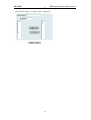
1
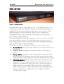
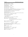
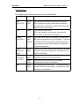
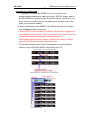
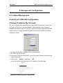
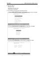
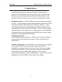
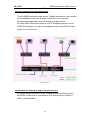
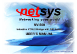
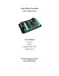
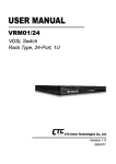
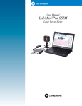
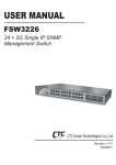
NH-800SP
__
HPNA Switch User Guide Ver.A.6
HPNA Solution
The HPNA NH-800SP networking solution delivers cost-effective, high-performance
broadband access to multiunit buildings (hotels, apartment, and multi-tenant unit office
buildings) and enterprise campus environments such as manufacturing, educational
campuses, and medical facilities. HPNA technology dramatically extends Ethernet over
existing Category 1/2/3 wiring at speeds 1Mbps (Half duplex) and distances up to 500
meters. The HPNA technology delivers broadband service on the same lines as Plain Old
Telephone Service (POTS), digital telephone, and ISDN system. In addition, HPNA
supports modes compatible with symmetric digital subscriber line , allowing service
providers to provision HPNA to buildings where broadband services already exist.
The HPNA solution includes HPNA NH-800SP (HPNA switches), and HPNA Modem for
Customer Premise Equipment (CPE) device.
The HPNA solution delivers everything needed to quickly deploy an Ethernet-based
network with the performance required to deliver high-speed Internet access at much
greater distances and drive services like IP telephony and audio/video streaming. With this
technology, a broad range of customers can benefit from lower operating costs and rapid
deployment. The HPNA solution provides multicast, Layer 2 quality of service (QOS),
MAC filtering security, GVRP, IGMP for VOD (Video on demand) and SNMP RMON
management and Web-based Switch network management.
The HPNA NH-800SP is a bridge between external Internet backbone through a router for
IP sharing and the building 110D telephone rack or telephone box. It utilizes the
available telephone wire to enable high-speed Internet access to building residents.
The NH-800SP uses the phone line networking technology endorsed by the HPNA (Home
Phoneline Network Alliance), and the NH-800SP utilizes the already existing telephone
wire to deliver 1 Mbps Internet access on each RJ-11 port.
This gives users a low-cost, end-to-end solution and eliminates the need to train installation
teams on multiple systems.
1
NH-800SP
__
HPNA Switch User Guide Ver.A.6
HPNA SWITCH
Figure 1:HPNA SWITCH
The HPNA SWITCH has 8x 1Mbps HPNA ports and 2 x 10/100M Ethernet ports. The
switches is one rack-unit (1RU) high, 10-inches deep. It is a standard Rack mounted size.
HPNA SWITCH switches deliver dedicated bandwidth per port at rates up to 1 Mbps.
HPNA transmissions coexist with POTS and ISDN, and can be compatible with
ADSL/HomePNA traffic in the same building. The switches can be configured on a
per-switch basis to support 500 meters.
The HPNA NH-800SP and HPNA Modem provide fast and easy connectivity into building
patch panels with RJ-11 connector. The 10/100 Ethernet ports can be used to connect
servers, Ethernet switches. These connectivity options provide multiple price/performance
options to meet building and budget requirements.
The HPNA switches provide the important features necessary for robust networks:
Quality of Service: 802.1p QoS support. Provides high-and low-priority queuing on a
per-port basis.
Supports: IGMP Snooping by 512 IP multicast table for VOD (Video on
demand)
Security: 802.1Q tagging-based and 802.1V protocol-based and port base virtual
local-area network (VLAN) support. Private VLAN access, assuring port security
without requiring a VLAN per port, and also supports GVRP dynamic VLAN setting.
Network Management: HPNA Switch technology support Telnet and Web-based
Management easy-to-use configuration and ongoing monitoring. This software is
embedded in the HPNA SWITCH and delivers remote, intuitive management of
HPNA switch and connected HPNA CPE devices through a single IP address.
HPNA switches are easy-to-configure and deploy, and offer a compelling option in
terms of cost, performance, scalability and services compared to traditional
ATM-based xDSL solutions.
2
NH-800SP
__
HPNA Switch User Guide Ver.A.6
Port Mirroring:NH-800SP supports port mirroring for HPNA port, this function
can special monitor client side as duplicate mail, Http…..etc, but need to be use
with application software.
Speed : NH-800SP support 0.7/1M speed setting.
Power Level : NH-800SP support High/Low power level setting.
Spanning tree: NH-800SP supports IEEE-802.1d spanning tree for avoid loop
and MAC bridge with redundant link
MAC address filtering:NH-800SP supports MAC address filtering security, and
MAC learning enable/disable.
TFTP Firmware upgrade: NH-800SP supports TFTP protocol for remote
firmware upgrade using.
SNMP: NH-800SP support very strong SNMP function, as RFC-1213
MIBII; RFC-1493 Bridge MIB; RFC-1643 Ether like MIB; RFC-1757
RNOM MIB; and support 1,2,3,9 RMON groups.
Configuration setting value backup and restore: NH-800SP supports setting
value backup and restore through TFTP function.
Default value setting: NH-800SP supports recovery manufacturing setting
value function.
Remote reboot: NH-800SP supports remote reboot machine through HTTP and
Telnet.
Telnet and console setup time limit: If on Login setup manual no key in any
Word within 10 second period, will be auto logout.
Preventing Hacker : To avoid hacker to enter management system through
client side, NH-800SP will filter system IP from client side for preventing hacker
attacking.
3
NH-800SP
__
HPNA Switch User Guide Ver.A.6
Table of Contents
1. Unpacking Information
Check List............................................................. 4
Product Features .................................................. 6
2. General Description
Hardware Description ........................................... 9
Front Panel ........................................................... 9
LED Indications .................................................... 11
Rear Panel............................................................ 12
3. Installation
Hardware Installation............................................ 13
Pre-Installation Requirements .............................. 13
General Rules....................................................... 13
Connecting the NH-800SP ................................... 14
Connecting “MDI-X” station Port........................... 14
Connecting “MDI" Port (TX) ................................ 14
Cascading configuration ....................................... 16
4. Management Configuration
In-Band Management
Console port (RS-232) configuration ..................... 17
Remote Network Control ...................................... 20
HPNA Speed Control and port Enable/Disable............. 27
5. Applications ........................................................ 39
Appendix A: Troubleshooting ............................... 42
Appendix B: V-LAN set up sample ..................... 46
FCC Warning ..................................................................48
Warranty………………………………………………..49
4
NH-800SP
__
HPNA Switch User Guide Ver.A.6
1.Unpacking Information
Check List
Carefully unpack the package and check its contents against the checklist.
Package Contents
1. HPNA NH-800SP
2 x10/100 Base-T N-way Ethernet ports and 8 x 1Mbps
HPNA ports
2. Users manual CD
3. AC Power Core
4. 2x Rack Mounting Brackets
5. 4x Screws
6. 4x Plastic feet
Please inform your dealer immediately for any missing, or damaged
parts. If possible, retain the carton, including the original packing
materials. Use them to repack the unit in case there is a need to return
for repair.
5
NH-800SP
__
HPNA Switch User Guide Ver.A.6
Product Guide
Product Name:2ports 10/100 Mbps Fast Ethernet plus 8Ports 1Mbps
HPNA With SNMP Management NH-800SP
Features
Supports Bandwidth setup with 1/0.7 Mbps HPNA ports
Build in POTS/ISDN filter(Splitter)
High Bandwidth up to 1Mbps
Long driver capable 500 meters
Supports GARP/GVRP 802.1p/q tag VLAN
Supports 802.1p QOS
Supports IGMP/v1 with Multicast IP with 512 groups
Supports IEEE 802.1d Multi Spanning trees for MAC bridge with redundant
link
Supports Auto noise floor adjustment
Supports port Mirroring function
Supports maximum bridge transit delay bound
Support Broadcast Storm filtering
Ethernet transport with POTS / ISDN traffic over single copper wire pair
Supports port security with MAC address filtering
Supports client cannot control NH-800SP from HPNA port
Supports Web Base and Telnet for remote control access
Provides POST(Power On Self Test) LED
Supports SNMP v1 RFC-1493 Bridge MIBs
RFC-1643 Ethernet MIB
RFC-1213 MIB II
Supports RMON MIB RFC1757 for groups 1(Statistics), 2(Alarm),
3(Event), 9(History)
Cascading up to 8 Units along with 8 ports switch
Supports TFTP/xmodem for firmware upgrade
Supports In-Band/Out-of-Band Management
Product Specifications:
Compliant with IEEE 802.3 & 802.3u Ethernet Standards
6
NH-800SP
__
HPNA Switch User Guide Ver.A.6
Compliant with HPNA 1.1 Standard
10/100Mbps Ethernet ports:2 x RJ-45
MDI Ethernet port : 1 x RJ-45
1 Mbps HPNA port :8 x RJ-11
POTS/ISDN Splitter port : 8 x RJ-11
MAC address table::8K Entries
Switching method : Store-and-forward
Flow control method by IEEE802.3x for Full Duplex & Back Pressure for Half Duplex
Compliant with GVRP IEEE 802.1q port-base VLAN with 4094 VID
Compliant with IEEE 802.1v protocol-base VLAN classification
Compliant with IEEE 802.1d Spanning trees
Multicast IP table :512
Compliant with IEEE 802.1p QOS by class of service with 2-level priority queuing
RS-232 console port ::DB-9Pin Female / 9600bps
SNMP v1 RFC-1493 Bridge MIBs
RFC-1643 Ethernet MIB
RFC-1213 MIB II
RMON groups 1(Statistics), 2(Alarm), 3(Event), 9(History)
Port security by MAC address filtering
LED indication :Power good and System ERR LED
Link/Active/Speed/Full Duplex Status for Ethernet port.
Link for HPNA port.
Power consumption :8.7 watts
HPNA Frequency Spectrum:Transmitter :5.5 ~ 9.5 MHz
Receiver:5.5 ~ 9.5MHz
POTS/ISDN Band pass filter Spectrum :0 ~ 1MHz
Internal switching power adapter Input: AC 85-265 volts/50-60Hz/1A.
Dimensions: 435 x 230 x 44 mm
Weight :3 Kg
Power consumption: 8.7 Watts
Operating Temperature : 5℃ ~ 50℃(41F ~ 122F)
Storage Temperature : - 20℃ ~ 65℃(-4F ~ 149F)
Humidity: 10%~90% non-condensing
EMI :FCC & CE Mark
7
NH-800SP
__
HPNA Switch User Guide Ver.A.6
2. General Description
Hardware Description
This section describes the important parts of the NH-800SP. It features the
front and rear panel drawings showing the LED, connectors, and
switches.
Front Panel
The following figure shows the front panel.
Figure Chapter 2.1 Front Panel description
Front panel.
(1) “PWR.”: Power Led light
(2) “POST”: System boot OK Led light
(3) 2X10/100 Mbps auto-sensing N-way Ethernet ports
(4) 8X1 Mbps HPNA Ports.
(5) 8XPOTS Ports.
(6) RS-232 Console Port
(7) Reset Button
HPNA SWITCH has embedded Splitter between every HPNA side and
POTS side. It permit you can delivers broadband service on the same
lines as Plain Old Telephone Service (POTS), PBX, ISDN traffic and
HPNA Signal.
Several LED indicators for monitoring the device itself, and the network
status. At a quick glance of the front panel, the user would be able to tell if
the product is receiving power; if it is monitoring another NH-800SP or
NH-800SP; or if a problem exists on the network.
Each port is labeled with a port number.
8
NH-800SP
__
HPNA Switch User Guide Ver.A.6
MDI port labeled with “TX” is shared from port T.
Do not use the same section bearing the markings of T and TX port
otherwise, failure will occur.
Figure Chapter 2.2
The "TX" port is used for connecting another hub through an ordinary
straight-wired twisted-pair cable by running one end of straight cable to “TX”
port and the other end to another NH-800SP or hub’s station port.
9
NH-800SP
__
HPNA Switch User Guide Ver.A.6
LED Indications
The following describes the function of each LED indicator.
LEDs
Status
Descriptions
PWR.
Steady
This LED light is located at the left side on the front
(Power LED)
Green
panel. It will light up (ON) to show that the product is
receiving power. Conversely, no light (OFF) means the
product is not receiving power.
POTS
Steady
POTS(Power On Self Test)
POTS Led will light to show system is booting now.
When system is ready the led will light off.
LINK/ACT
Steady
Each RJ45 station port on the Ethernet is assigned an
(Link LEDs)
Green
LED light for monitoring port “Good Linkage”.
Flashing
is normally OFF after the power on operation, but will
Each LED
light up steadily to show good linkage. And Flashing to
show data transmission.
Speed
Steady
Indicates that communications have been set 100 Mbps.
(Speed 100
Yellow
Each port on the hub is assigned an LED light for 100
Base-TX connecting.
LEDs)
FD
Steady
Indicates that communications have been set to
(Full-Duplex
Yellow
full-duplex operation for the indicated port
LEDs LEDs)
Steady
The indicator lights up working in Full Duplex
Yellow
And light down working in Half Duplex
Steady
RJ11 LED is lit up to show “Link”.
Green
CO and CPE side connecting OK, and light down which
LINK
Meaning is no connecting.
10
The indicator both
NH-800SP
__
HPNA Switch User Guide Ver.A.6
Rear Panel
The following figure shows the rear panel
Figure Chapter 2.3 Rear Panel
AC 100~240V
AC Power Socket
The power cord should be plug into this socket. The AC Socket accepts
AC power 100 to 240 voltage. 1A.
11
NH-800SP
__
HPNA Switch User Guide Ver.A.6
3.Installation
Hardware Installation
This chapter describes how to install the NH-800SP. To established
network connection. You may install the NH-800SP on any level surface
(table, shelf, 19 inch rack or wall mounting). However, please take note
of the following minimum site requirements before you begin.
Pre-Installation Requirements
Before you start actual hardware installation, make sure you can provide
the right operating environment, including power requirements, sufficient
physical space, and proximity to other network devices that are to be
connected. Verify the following installation requirement:
Power requirements: AC 100V to 240 V at 50 to 60 Hz.
The Switch power supply automatically adjusts to the input voltage
level.
The NH-800SP should be located in a cool dry place, with at least
10cm/4in of space at the front and back for ventilation.
Place the NH-800SP out of direct sunlight, and away from heat sources
or areas with a high amount of electromagnetic interference.
Check if network cables and connectors needed for installation are
available.
General Rules
Before making any connections to the NH-800SP, note the following rules:
Ethernet Port (RJ-45)
All network connections to the NH-800SP Ethernet port must be made
using Category 5 UTP for 100Mbps and Category 3,4 UTP for 10Mbps.
No more than 100 meters (about 328 feet) of cabling may be use
between NH-800SPs or with HUB or an end node.
HPNA Port (RJ-11)
All home network connections to the HPNA
Port made using 24 ~ 26 Gauge phone wiring.
We do not recommend using 28 Gauge or above phone line.
12
NH-800SP
__
HPNA Switch User Guide Ver.A.6
Connecting the NH-800SP
The NH-800SP has 2 10/100 Mbps N-way ports which support connection
to 10Base-T Ethernet or 100Base-TX Fast Ethernet. Support full or
half-duplex operation. The transmission mode is using auto-negotiation.
Therefore, the devices attached to these ports must support
auto-negotiation unless they will always operate at half duplex. If
transmissions must run at full duplex, but the attached device does not
support auto-negotiation, then you should upgrade this device to a newer
version that supports auto-negotiation.
Use “T” port to connect to devices such as a cable modem, server, bridge
or router. You can also cascade to another compatible MUX or hub by
connecting the UP-Link port to an “MDI” port (e.g., port TX on this switch)
on the other device.
Connecting “MDI-X” Station Port
1. You can connect the “T” port on the NH-800SP to any device that uses
a standard network interface such as a Cable modem, ADSL modem,
Ethernet Switch, workstation or server, or also to a network
interconnection device such as a bridge or router (depending on the
port type implemented).
2. Prepare the network devices you wish to connect. Make sure you
have installed suitable HPNA Modem before making a connection to
any of the HPNA SWITCH (1-8) station ports. You also need to
prepare 18 ~ 26 gauge one twist pair phone Line wiring with RJ-11
plugs at both ends.
3. Connect one end of the cable to the RJ-11 port of the Home Access
network adapter, and the other end to any available (1~8) station port
on the HPNA. Every port supports 10 Mbps connections. When
inserting an RJ-11 plug, be sure the tab on the plug clicks into position
to ensure that it is properly seated.
● Do not plug a RJ-11 phone jack connector into the Ethernet port
(RJ-45 port). This may damage the HPNA. Instead, use only
twisted-pair cables with RJ-45 connectors that conform the FCC
standards.
13
NH-800SP
__
HPNA Switch User Guide Ver.A.6
Notes:
1. Be sure each twisted-pair cable (RJ-45) is not over by 100 meters (328
feet).
2. RJ-11 port use 18 ~ 26 gauge phone wiring, 28 gauge or above is not
recommended.
3. We advise using Category 5 cable for Cable Modem or router
connections or to attach to any high bandwidth device to avoid any
confusion or inconvenience.
Connecting “MDI” Port (TX)
Prepare straight through shielded or unshielded twisted-pair cables with
RJ-45 plugs on both ends. Use 100Ω Category 5 cable for connections.
Connect one end of the cable to “TX” port of the NH-800SP, and the other
end to a standard RJ-45 station port on cable modem, ADSL router,
wireless bridge, etc. When inserting an RJ-45 plug, be sure the tab on the
plug clicks into position to ensure that it is properly seated.
Notes:
Make sure the length of twisted-pair cable is not over by 100 meters (328
feet)
14
NH-800SP
__
HPNA Switch User Guide Ver.A.6
Cascading Configuration
1. To connect to another NH-800SP or hub, you may also run
straight-through twisted-pair cabling from the “EXP IN” station port on
the NH-800SP to a crossover port on another device. However, if you
must connect to another device via station ports on both ends of the
cable, use crossover cabling.
2. When cascading two NH-800SPs, the default setting are full duplex
and 100Mbps for daisy-chain port.
3. HPNA SWITCH can cascade up to 8 Units. But we don’t suggest you
cascading more than 3 Units. When you cascade mort than 3 units the
network performance will be badly, because packet by
Store-and-forward Switching method, packet will be delay, to effect
upper NH-800SP performance to be slow down.
IF you want cascade more than 3 units please use 8 port switch to
connect every HPNA NH-800SP. Follow the figure 3.2
Figure Chapter 3.1 UP-Link Configuration
Figure Chapter 3.2 VLAN Hub UP-Link Configuration
15
NH-800SP
__
HPNA Switch User Guide Ver.A.6
4. Management Configuration
4.1 In-Band Management
Console port (RS-232) Configuration
(Change IP Address By Terminal)
You can configure the product with the local serial console port, If one of the
RJ11 port is not in use, you can disable it, that procedure is to connect a
notebook computer to the RS-232 port, then boot windows @95/98/ME/2000
system, and run “Hyper-terminal” program into terminal window, and setup
step are as follow.
1. Set “Bits per second” at 9600 to the content window.
2. Set “Flow control” at None
3. Connects PC with the NH-800SP, you will find login manual window on the
screen then enter
Login name :”admin” ; password:”123”
you will find user manual window on the screen of the following :
16
NH-800SP
__
HPNA Switch User Guide Ver.A.6
4. Operation Button:
Tab=Next Item ;
BackSpace=Previous Item
Enter=Select ItemSelect
5. Set IP Address: Please follow the following steps
(1) Choose HPNA SWITCH Static Configuration you can enter next page
(2) Choose Administration Configuration you can enter next page
(3) Choose IP Configuration you can enter IP configuration page
17
NH-800SP
__
HPNA Switch User Guide Ver.A.6
(4) a. Choose Edit item to Change IP address, Subnet Mask and Getway
b. Use CTRL+A button to back actions choice
c. Choose Save item to save change and back to System Configuration
page
d. Choose Previous Menu item to quit System Configuration page
e. Choose Main Menu item to quit HPNA SWITCH Configuration page
and back to Main Manual
f. Choose Reboot NH-800SP item
g. Choose Restart item to reboot your HPNA SWITCH.
18
NH-800SP
__
HPNA Switch User Guide Ver.A.6
4.2 Remote Network Management
4.2.1 IP Setting
You must setup the “IP Address” with the local serial console port (RS-232
Port), and then you can use this IP address to control this HPNA NH-800SP
by Telnet and WEB. Or you can change your computer’s IP domain same with
HPNA SWITCH. Then use the default IP address to control this HPNA
NH-800SP.
㆒、Remote control by “Telnet”
To enter Telnet, type the IP address of the HPNA switch to connect
management system. And type User name and password.
Default User Name: admin
Default Password: 123
Note:
1. For secretary we limit the user login number on Telnet and Console port.
So you can’t login Telnet and Console port in the same time. But you
can login Telnet and Console port in the different time, if you login in
Consol manual, But without key in any word 10 second period, system
will be auto logo out.
2. WEB Login don’t limit user login numbers.
When you want to close console port control you must logout to leave.
Otherwise you can’t login by Telnet.
㆓、Network control by “WEB”
4.2.2 Web Management Function
1. Provide a Web browser to manage and monitor the switch, the default values as follows:
If you need change IP address in first time, you can use console mode to modify it.
IP Address: 192.168.16.250
Subnet Mask: 255.255.255.0
Default Gateway: 192.168.16.1
User Name: admin
Password: 123
2. You can browse http:// 192.168.16.250, type user name and password as above.
19
NH-800SP
__
HPNA Switch User Guide Ver.A.6
4.2.2-1. Web Management Home Overview
This is HPNA Home Page.
4.2.2-2. Port status
1. This page can see every port status
State: Display port status disable or enable, disable is unlink port, enable is link port.
Link Status: Down is “No Link”, UP is “Link”
Auto Negotiation: Switch auto negotiation mode
Speed status: Port 9、10 are 10/100Mbps or and Port 1- 8 are 1Mbps,
Configure: Display the state of user setup,
Actual: Display the negotiation result.
Duplex status: Display full-duplex or half-duplex mode.
Configure: Display the user setup,
Actual: Display the negotiation result.
Flow control: Display flow control status enable or disable mode
20
NH-800SP
__
HPNA Switch User Guide Ver.A.6
User can see single port counter as follows
4.2.2-3. Port Statistics
1. The following information provides a view of the current status of the unit.
21
NH-800SP
__
HPNA Switch User Guide Ver.A.6
4.2.2-4. Administrator
There are many management function, include:
IP address
Switch setting
Console port information
Port controls
Link aggregation
Filter database
VLAN configuration
Spanning tree
SNMP
Security Manager
System Manager
Configuration backup
Reset system and reboot
4.2.2-4-1. IP Address
1. User can configure the IP Settings and fill in the new value, than clicks apply button.
2. User must be reset switch and use new IP address to browser this web management.
Default IP is 192.168.16.250
22
NH-800SP
__
HPNA Switch User Guide Ver.A.6
4.2.2-4-2. Switch Setting
2-4-2-1.Basic
1. Description: Display the device type of name.
2. MAC Address: The unique hardware address assigned by manufacturer
3. Firmware Version: Display the switch’s firmware version.
4. Hardware Version: Display the switch’s Hardware version.
5. Default config value version: Display write to default eeprom value tale version.
23
NH-800SP
__
HPNA Switch User Guide Ver.A.6
2-4-2-2.Advanceed
Miscellaneous Setting :
MAC Address Age-out Time: Type the number of seconds that an inactive MAC address remains in
the switch's address table. The valid range is 300~765 seconds. Default is 300 seconds.
Max bridge transit delay bound control : Limit the packets queuing time in switch. If enable, the
packets queued exceed will be drop. This valid value are 1sec, 2 sec, 4 sec and off. Default is 2
seconds.
Broadcast Storm Filter: To configure broadcast storm control, enable it and set the upper threshold
for individual ports. The threshold is the percentage of the port's total bandwidth used by broadcast
traffic. When broadcast traffic for a port rises above the threshold you set, broadcast storm control
becomes active. The valid threshold value are 5%, 10%, 15%, 20%, 25% and off.
Priority Queue Service settings:
First Come First Service: The sequence of packets sent is depend on arrive order.
All High before Low: The high priority packets sent before low priority packets.
Weighted Round Robin: Select the preference given to packets in the switch's high-priority queue.
These options represent the number of high priority packets sent before one low priority packet is sent.
For example,5 High : 2 Low means that the switch sends 5 high priority packets before sending 2 low
priority packet.
Enable Delay Bound: Limit the low priority packets queuing time in switch. Default Max Delay Time
is 255ms. If the low priority packet stays in switch exceed Max Delay Time, it will be sent. The valid
range is 1~255 ms.
NOTE: Make sure of “Max bridge transit delay bound control” is enabled before enable Delay Bound,
because Enable Delay Bound must be work under “Max bridge transit delay bound control is enabled”
situation.
Qos Policy: High Priority Levels: 0~7 priority level can map to high or low queue.
24
NH-800SP
__
HPNA Switch User Guide Ver.A.6
Protocol Enable Setting :
Enable Spanning Tree Protocol : Default recommend to enable STP
Enable Internet Group Multicast Protocol: enable IGMP protocol
VLAN Protocol:
802.1Q(Port_Based) without GVRP VLAN mode
802.1Q(Port_Based) with GVRP VLAN mode
Port_Based VLAN mode
GVRP (GARP [Generic Attribute Registration Protocol] VLAN Registration Protocol)
GVRP allows automatic VLAN configuration between the switch and nodes. If the switch is connected
to a device with GVRP enabled, you can send a GVRP request using the VID of a VLAN defined on
the switch, the switch will automatically add that device to the existing VLAN.
4.2.2-4-3. Console Port Information
1. Console is a standard UART interface to communicate with Serial Port.
User can use windows HyperTerminal program to link the switch. Connect To->Configure
Bits per seconds: 9600
Data bits: 8
Parity: none
STOP BITS: 1
Flow control: none
25
NH-800SP
__
HPNA Switch User Guide Ver.A.6
4.2.2-4-4. HPNA Speed Control and port Enable/Disable
This page can Change every port status and speed mode
State: You can disable or enable HPNA port control
Speed: You can change HPNA Speed mode by 0.7Mbps, 1Mbps
Change Speed procedure:
a. Confirm the HPNA port is linking which you want change speed mode.
b. Make sure HPNA port has been connecting to HPNA Modem and Link up OK.
c. Select the port
d. Select the speed mode(High is 1Mbps, Low is 0.7Mbps)
e. Click “Apply”
f. HPNA port will link up again during the new speed mode.
4.2.2-4-6. Filter Database
2-4-6-1. IGMP Snooping
The HPNA SWITCH support IP multicast , you can enable IGMP protocol on web management’s
switch setting advanced page, then display the IGMP snooping information in this page, you can view
difference multicast group ,VID and member port in here, IP multicast addresses range from 224.0.0.0
through 239.255.255.255.
The Internet Group Management Protocol (IGMP) is an internal protocol of the Internet Protocol (IP)
suite.
IP manages multicast traffic by using switches, routers, and hosts that support IGMP. Enabling IGMP
allows the ports to detect IGMP queries and report packets and manage IP multicast traffic through the
switch. IGMP have three fundamental types of message as follows:
26
NH-800SP
__
Message
Query
Report
Leave Group
HPNA Switch User Guide Ver.A.6
Description
A message sent from the queries (IGMP router or switch) asking for a
response from each host belonging to the multicast group.
A message sent by a host to the queries to indicate that the host wants to
be or is a member of a given group indicated in the report message.
A message sent by a host to the queries to indicate that the host has quit
to be a member of a specific multicast group.
27
NH-800SP
__
HPNA Switch User Guide Ver.A.6
2-4-6-2. Static MAC Address
When you add a static MAC address, it remains in the switch's address table, regardless of whether the
device is physically connected to the switch. This saves the switch from having to re-learn a device's
MAC address when the disconnected or powered-off device is active on the network again.
1. To add a static MAC address
2. From the main menu, click administrator, then click Filter Database.
3. Click Static MAC Addresses. In the MAC address box, enter the MAC address to and from which
the port should permanently forward traffic, regardless of the device's network activity.
4. In the Port Number box, select a port number.
5. If tag-based (IEEE 802.1Q) VLANs are set up on the switch, static addresses are associated with
individual VLANs. Type the VID (tag-based VLANs) to associate with the MAC address.
6. Click add
2-4-6-3. Port Security
A port in security mode will be “locked” without permission of address learning. Only the incoming
packets with SMAC already existing in the address table can be forwarded normally. User can disable
the port from learning any new MAC addresses, then use the static MAC addresses screen to define a
list of MAC addresses that can use the secure port.Enter the settings, then click Submit to apply the
changes on this page.
28
NH-800SP
__
HPNA Switch User Guide Ver.A.6
2-4-6-4. MAC filtering
MAC address filtering allows the switch to drop unwanted traffic. Traffic is filtered based on the
destination addresses. For example, if your network is congested because of high utilization from one
MAC address, you can filter all traffic transmitted from that MAC address, restoring network flow
while you troubleshoot the problem.
29
NH-800SP
__
HPNA Switch User Guide Ver.A.6
4.2.2-4-7. VLAN configuration
A Virtual LAN (VLAN) is a logical network grouping that limits the broadcast domain. It allows you
to isolate network traffic so only members of the VLAN receive traffic from the same VLAN members.
Basically, creating a VLAN from a switch is logically equivalent of reconnecting a group of network
devices to another Layer 2 switch. However, all the network devices are still plug into the same switch
physically.
The HPNA SWITCH support port-based and protocol-base VLAN in web management page, In the
default configuration, VLAN support is enable and all ports on the switch belong to default VLAN,
VID is 1.
Support Tagging-based VLANs (IEEE 802.1Q VLAN)
Port-based Tagging rule VLAN is an IEEE 802.1Q specification standard. Therefore, it is possible to
create a VLAN across devices from different switch venders. IEEE 802.1Q VLAN uses a technique to
insert a “tag” into the Ethernet frames. Tag contains a VLAN Identifier (VID) that indicates the VLAN
numbers.
Support Protocol-based VLAN
In order for an end station to send packets to different VLANs, it itself has to be either capable of
tagging packets it sends with VLAN tags or attached to a VLA N-aware bridge that is capable of
classifying and tagging the packet with different VLAN ID based on not only default PVID but also
other information about the packet, such as the protocol.
HPNA SWITCH will support protocol-based VLAN classification by means of both built-in
knowledge of layer 2 packet formats used by selected popular protocols, such as Novell IPX and
AppleTalk’s EtherTalk, and some degree of programmable protocol matching capability.
30
NH-800SP
__
HPNA Switch User Guide Ver.A.6
2-4-7-1. Basic
Create a VLAN and add tagged member ports to it.
1. From the main menu, click administrator -- VLAN configuration.
2. Click Add
3. Type a name for the new VLAN.
4. Type a VID (between 2-4094). The default is 1.
5. From the Available ports box, select ports to add to the switch and click Add.
6. Click Apply
31
NH-800SP
__
HPNA Switch User Guide Ver.A.6
2-4-7-2. Port VID
Configure port VID settings
From the main Tag-based (IEEE 802.1Q) VLAN page, click Port VID Settings.
Port VID (PVID)
Sets the Port VLAN ID that will be assigned to untagged traffic on a given port. For example, if port
10's Default PVID is 100, all untagged packets on port 10 will belong to VLAN 100. The default
setting for all ports is VID 1.
This feature is useful for accommodating devices that you want to participate in the VLAN but that
don't support tagging. Only one untagged VLAN is allowed per port.
Ingress Filtering
Ingress filtering lets frames belonging to a specific VLAN to be forwarded if the port belongs to that
VLAN.
HPNA SWITCH have two ingress filtering rule as follows :
Ingress Filtering Rule 1 :Forward only packets with VID matching this port's configured VID
Ingress Filtering Rule 2 :Drop Untagged Frame
32
NH-800SP
__
HPNA Switch User Guide Ver.A.6
4.2.2-4-8. Spanning Tree
The Spanning-Tree Protocol (STP) is a standardized method (IEEE 802.1D ) for avoiding loops in
switched networks. When STP enabled, to ensure that only one path at a time is active between any
two nodes on the network.
You can enable Spanning-Tree Protocol on web management’s switch setting advanced item, select
enable Spanning-Tree protocol. We are recommended that you enable STP on all switches ensures a
single active path on the network.
1. You can view spanning tree information about the Root bridge. such as follow screen.
2. You can view spanning tree status about the switch . such as follow screen.
33
NH-800SP
__
HPNA Switch User Guide Ver.A.6
3. You can setting new value for STP parameter , then click set Applybutton to modify .
Parameter
Priority
Description
You can change priority value, A value used to identify the root bridge. The bridge
with the lowest value has the highest priority and is selected as the root. Enter a
number 1 through 65535.
You can change Max Age value, The number of seconds a bridge waits without
Max Age
receiving . Spanning-Tree Protocol configuration messages before attempting a
reconfiguration. Enter a number 6 through 40.
Hello Time
Forward
Delay time
You can change Hello time value, the number of seconds between the transmission
of Spanning-Tree Protocol configuration messages. Enter a number 1 through 10.
You can change forward delay time, The number of seconds a port waits before
changing from its Spanning-Tree Protocol learning and listening states to the
forwarding state. Enter a number 4 through 30.
4.The following parameter can be configured on each port , click set Apply button to modify .
Parameter
Description
You can make it more or less likely to become the root port, the rage is
Port Priority
0-255,default setting is 128 the lowest number has the highest priority.
If you change the value, you must reboot the switch.
Specifies the path cost of the port that switch uses to determine which port are
Path Cost
the forwarding ports the lowest number is forwarding ports, the rage is
1-65535 and default value base on IEEE802.1D 10Mb/s = 50-600 100Mb/s =
10-60 1000Mb/s = 3-10 If you change the value, you must reboot the
switch.
34
NH-800SP
__
HPNA Switch User Guide Ver.A.6
4.2.2-4-9. Port Sniffer
The Port Sniffer is a method for monitor traffic in switched networks. Traffic through ports can be
monitored by one specific port. That is, traffic goes in or out monitored ports will be duplicated into
sniffer port.
Roving Analysis State: Enable or disable the port sniffer function.
Analysis Port: Analysis port can be used to see all monitor port traffic. You can connect sniffer port to
Lan Analysis, Session Wall or Netxray.
Monitor Ports: The ports you want to monitor. All monitor port traffic will be copied to sniffer port.
You can select max 9 monitor ports in the switch. If you want to disable the function, you must select
monitor port to none.
Monitor Rx: Monitored receive frames from the port.
Monitor Tx: Monitored send frames from the port.
35
NH-800SP
__
HPNA Switch User Guide Ver.A.6
4.2.2-4-10. SNMP
Any Network Management running the simple Network Management Protocol (SNMP) can
management the switch, Provided the Management Information Base (MIB) is installed correctly on
the management station. The SNMP is a Protocol that governs the transfer of information between
management and agent. The HPNA SWITCH support SNMP V1.
1. Use this page to define management stations as trap managers and to enter SNMP community
strings. User can also define a name, location, and contact person for the switch. Fill in the
system options data, and then click Apply to update the changes on this page
Name: Enter a name to be used for the switch.
Location: Enter the location of the switch.
Contact: Enter the name of a person or organization.
2. Community strings serve as passwords and can be entered as one of the following:
Read only: Enables requests accompanied by this string to display MIB-object information.
Read write: Enables requests accompanied by this string to display MIB-object information and to set
MIB objects.
3. Trap Manager
36
NH-800SP
__
HPNA Switch User Guide Ver.A.6
A trap manager is a management station that receives traps, the system alerts generated by the switch.
If no trap manager is defined, no traps are issued. Create a trap manager by entering the IP address of
the station and a community string.
Enterprise mib contains two traps:
a. When HPNA switch internal temperature is greater than 70℃, system will send a “Temperature alarm
“ trap.
b. When HPNA switch internal cooling FAM don’t run, system will send a “FAM speed alarm” trap.
4.2.2-4-11.Security Manager
1. Use this page; user can change web management user name and password.
User name: Admin
Password: 123
4.2.2-4-12. TFTP Update Firmware
1. The following menu options provide some system control functions to allow a user to update
firmware and remote boot switch system:
* Install TFTP Turbo98 and execution.
* Copy firmware update version image.bin to TFTP Turbo98 directory.
* In web management select administrator—TFTP update firmware.
* Download new image.bin file then in web management press <update firmware>.
37
NH-800SP
__
HPNA Switch User Guide Ver.A.6
4.2.2-4-13. Configuration Backup
2-4-13-1. TFTP Restore Configuration
Use this page to set tftp server address. You can restore EEPROM value from here, but you must put
back image in tftp server, switch will download back flash image.
2-4-13-2. TFTP Backup Configuration
Use this page to set tftp server ip address. You can save current EEPROM value from here, then go to
the TFTP restore configuration page to restore the eeprom value.
4.2.2-4-14. Reset System
Reset NH-800SP to default configuration
4.2.2-4-15. Reboot
Reboot the NH-800SP in software reset
38
NH-800SP
__
HPNA Switch User Guide Ver.A.6
5. Applications
The HPNA provides home network architecture. Transforming an
apartment into a Multiple-Family Home network area, sharing a single
internet account for multiple users via Router & Cable Modem, it can
provide unlimited access time in the internet at a reasonable low price.
Bridging Functions – The NH-800SP provides full transparent bridging
function. It automatically connects node addresses, that are later used to
filter and forward all traffic based on the destination address. When
traffic passes between devices attached to the shared collision domain,
those packets are filtered from the NH-800SP. But when traffic must be
passed between unique segments (i.e., different ports of the NH-800SP),
a temporary link is set up between the NH-800SP’s port in order to pass
this traffic, via the high-speed HPNA fabric.
Transceiver function
The NH-800SP support Ethernet to HPNA convert, It can be transmit or
receive packet from Ethernet port to the RJ11 port. Or HPNA port to
Ethernet port.
Flexible Configuration–The NH-800SP is not only Designed to segment
your network, but also to provide a wide range of options in the
configuration of Home network connections. It can be used as a simple
stand-alone NH-800SP; or can be connected with another NH-800SP,
Cable modem, Router, XDSL, ISDN, gateway or other network
interconnection devices in various configurations. Some of the common
applications of the NH-800SP are described in this chapter.
39
NH-800SP
__
HPNA Switch User Guide Ver.A.6
Used as apartment for Internet access
The NH-800SP provides a high speed, 10Mbps transmission over existing
home telephone wiring over a single Internet account to provide
simultaneous independent Internet access to multiple users.
No mater ISDN Telephone system or POTS Telephone system you are.
HPNA Technology let you can use telephone system and HPNA network
system in the same time.
Figure Chapter 4.1
Application for Sharing a single internet account
If multiple users would like to share a single internet account using the
NH-800SP, which is to be connected to a IP sharing device, then to a
xDSL or Cable Modem.
40
NH-800SP
__
HPNA Switch User Guide Ver.A.6
Note:
For network applications that actually require
Router (e.g., Interconnecting dissimilar network types), attaching the
NH-800SP directly to a router can significantly improve overall home
networking performance.
High bandwidth backbone ready
The NH-800SP provides 10/100Mbps auto sensing for external trunk
device (Fiber optics, Wireless Bridge, xDSL & other WAN services)
41
NH-800SP
__
HPNA Switch User Guide Ver.A.6
Appendix A: Troubleshooting
Diagnosing HPNA Indicators
The HPNA can be easily monitored through its comprehensive panel
indicators. These indicators assist the network manager in identifying
problems the NH-800SP may encounter. This section describes common
problems you may encounter and possible solutions
1. Symptom: POWER indicator does not light up (green) after power
on.
Cause:
Defective power outlet, power cord, internal power supply
Solution: Cheek the power outlet by trying another outlet that is
functioning properly. Check the power cord with another
device. If these measures fail to resolve the problem, have
the unit power supply replaced by a qualified distributor.
2. Symptom: Link indicator does not light up (green) after making a
connection.
Cause:
Network interface (e.q., a network adapter card on the
attached device), network cable, or switch port is
defective.
Solution: 2.1 Verifies the switch and attached device are powered
on.
2.2 Be sure the cable is plug into both the switch and
corresponding device.
2.3 Verify that the proper cable type is used and its length
does not exceed specified limits.
2.4 Check the adapter on the attached device and cable
connections for possible defects.
2.5 Replace the defective adapter or cable if necessary.
3. Symptom: I had a HPNA link and data transmitted OK. after
disconnecting then change another one port, got link OK, but data
was not transmitted.
Solution: This phenomenon is not a problem, due to NH-800SP
base on Ethernet switch technologies designed, as power on that
first running on a MAC learning function for get each port MAC
address, and create a MAC table, so that will keep one port to match
one MAC address, if you change port or PC, will be MAC learning
failure cause data transmitting failure, unless restart NH-800S or
waiting several minutes(aging time) to clear MAC address.
4. Symptom: I have not control NH-800SP management from HPNA
Ports:
Solution: This phenomenon is not a problem, in order to prevent
42
NH-800SP
__
HPNA Switch User Guide Ver.A.6
Hacker attacking, NH-800SP auto filter management IP with user
Port(HPNA port).
5. Symptom: Router hang-up
Case: User use P2P download AP
Solution: Almost of SOHO Router just support session numbers
Between 1024 ~ 2048 session number, if encounter with
E-Donkey download AP, due to session numbers not
Enough, cause Router hang-up or some users can not
enjoy internet service, you must change a high session
numbers Router to replace that,
43
NH-800SP
__
HPNA Switch User Guide Ver.A.6
System Diagnostics
Power and Cooling Problems
If the POWER indicator does not turn on when the power cord is plugged
in, you may have a problem with the power outlet, power cord, or internal
power supply as explained in the previous section. However, if the unit
should turn itself off after running for a while, check for loose power
connections, power losses or surges at the power outlet, and verify that
the fan on back of the unit is unobstructed and running prior to shutdown.
If you still cannot isolate the problem, then the internal power supply may
be defective. In this case, contact your supplier for assistance.
Installation
Verify that all system components have been properly installed. If one or
more components appear to be malfunctioning (e.g., the power cord or
network cabling), test them in an alternate environment where you are
sure that all the other components are functioning properly.
Transmission Mode
The selections of the transmission mode for the RJ-45 ports are
auto-negotiation using the default method. Therefore, if the Link signal is
disrupted (e.g., by unplugging the network cable and plugging it back in
again, or by resetting the power), the port will try to reestablish
communications with the attached device via auto-negotiation. If
auto-negotiation fails, then communications are set to half duplex by
default. Based on this type of industry-standard connection policy, if you
are using a full-duplex device that does not support auto-negotiation,
communications can be easily lost (i.e., reset to the wrong mode)
whenever the attached device is reset or experiences a power fluctuation.
The best way to resolve this problem is to upgrade these devices to
version that will support auto-negotiation.
Cabling
1. Verify that the cable type is correct.
Be sure RJ-45 cable connectors
are securely seated in the required ports. Use 100Ω straight-through
cables for all standard connections. Use Category 5 cable for
44
NH-800SP
__
HPNA Switch User Guide Ver.A.6
100Mbps Fast Ethernet connections, or Category 3, 4 or 5 cables for
standard 10Mbps Ethernet connections. Be sure RJ-11 phone wiring,
use 18~26 gauge.
2. Make sure all devices are connected to the network. Equipment any
have been unintentionally disconnected from the network.
3. When cascading two devices using RJ-45 station ports at both ends of
the cable (i.e., not an MDI port), make sure a crossover cable is used.
Crossover cable should only be used if a MDI port is not available.
Physical Configuration
If problems occur after altering the network configuration, restore the
original connections, and try to track the problem down by implementing
the new changes, one step at a time. Ensure that cable distances and
other physical aspects of the installation do not exceed recommendations
System Integrity
As a last resort verify the switch integrity with a power-on reset. Turn the
power to the switch off and then on several times. If the problem still
persists and you have completed all the preceding diagnoses, contact
your dealer for assistance.
45
NH-800SP
__
HPNA Switch User Guide Ver.A.6
Appendix B: V-LAN Set up sample
Web management
protocol setting
Web management
Administrator Switch settings Advanced:
VLAN Operation Mode: Select “Port_Based”
Administrator
Switch settings Vlan Configuration:
46
NH-800SP
__
HPNA Switch User Guide Ver.A.6
Add VLAN Group 1, member: port 1 and port 9
47
NH-800SP
__
HPNA Switch User Guide Ver.A.6
FCC Warning
This equipment has been tested and found to comply
with the limits for a Class A digital device, pursuant to
Part 15 of the FCC Rules. These limits are designed
to provide reasonable protection against harmful interference when the equipment is operated in a commercial
environment. This equipment generates, uses, and can
radiate radio frequency energy and, if not installed and
used in accordance with the instruction manual, may
cause harmful interference to radio communications.
Operation of this equipment in a residential area is likely
to cause harmful interference in which case the user will
be required to correct the interference at his own expense.
CE Mark Warning
This is a CE class A product. In a domestic environment, this product may cause radio
interference in which case the user may be required to take adequate measures.
48
NH-800SP
__
HPNA Switch User Guide Ver.A.6
Warranty
Netsys to the original owner that the product delivered in this package will be free
from defects in material and workmanship for one year parts after purchase. For the
warranty to apply, you must register your purchase by returning the registration card
indicating the date of purchase.
There will be a minimal charge to replace consumable components, such as fuses,
power transformers, and mechanical cooling devices. The warranty will not apply to
any products which have been subjected to any misuse, neglect or accidental damage,
or which contain defects which are in any way attributable to improper installation or
to alteration or repairs made or performed by any person not under control of Netsys.
THE ABOVE WARRANTY IS IN LIEU OF ANY OTHER WARRANTY,
WHETHER EXPRESS, IMPLIED, OR STATUTORY, INCLUDING BUT NOT
LIMITED TO ANY WARRANTY OF MERCHANTABILITY, FITNESS FOR A
PARTICULAR PURPOSE, OR ANY WARRANTY ARISING OUT OF ANY
PROPOSAL, SPECIFICATION, OR SAMPLE. SHALL NOT BE LIABLE FOR
INCIDENTAL OR CONSEQUENTIAL DAMAGES. WE NEITHER ASSUMES
NOR AUTHORIZES ANY PERSON TO ASSUME FOR IT ANY OTHER
LIABILITY.
Trademarks
Copyright © Nation Enhance Technology Corp.
Contents subject to revision without prior notice.
Netsys is a registered trademark of National Enhance
Technology Corp.
The information in this manual is
subject to change without notice. All other trademarks
belong to their respective owners.
49