1
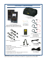
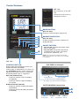
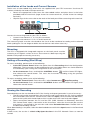
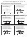
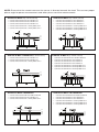
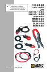
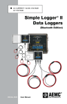
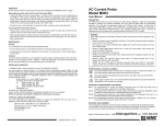
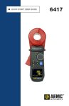
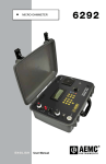
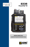
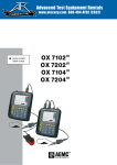
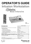
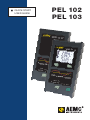
QUICK START USER GUIDE PEL 102 PEL 103 Statement of Compliance Chauvin Arnoux®, Inc. d.b.a. AEMC® Instruments certifies that this instrument has been calibrated using standards and instruments traceable to international standards. We guarantee that at the time of shipping your instrument has met its published specifications. An NIST traceable certificate may be requested at the time of purchase, or obtained by returning the instrument to our repair and calibration facility, for a nominal charge. The recommended calibration interval for this instrument is 12 months and begins on the date of receipt by the customer. For recalibration, please use our calibration services. Refer to our repair and calibration section at www.aemc.com. Serial #: _________________________________ Catalog #: 2137.51 / 2137.52 / 2137.61 / 2137.62 Model #: PEL 102 / PEL 103 Please fill in the appropriate date as indicated: Date Received: __________________________________ Date Calibration Due: ________________________ Chauvin Arnoux®, Inc. d.b.a AEMC® Instruments www.aemc.com PRODUCT PACKAGING Shipping Contents: (1) Small Classic Tool Bag Cat. #2133.72 (1) of the following: Power & Energy Logger Model PEL 102 Power & Energy Logger Model PEL 103 Cat. #2137.51 / 2137.52 / 2137.61 / 2137.62 (12) ID Markers Cat. #2140.45 (3) MiniFlex® MA193-10-BK Cat. #2140.48 (1) USB SD-Card Adapter (included only with Cat. #5000.45 the purchase of Cat. #2137.51 or Cat. #2137.52) (4) Black Test Leads and Alligator Clips Cat. #2137.76 Also Included: (1) Safety Sheet for the PEL (1) Multifix (mounting system) Cat. #5000.44 (1) Power Cord Cat. #5000.14 (1) Safety Sheet for the MiniFlex® Sensors (1) Compliance Sheet (1) 2 GB SD-Card (1) Quick Start User Guide (1) 4 GB USB Stick with User Manual & DataView® Software (1) 5 ft USB Cable Cat. #2140.46 (1) Battery (NiMH AAA 8.4V) - Cat.#2137.75 USB STICK: DataView® software and user manuals for the Power Energy Logger (PEL) and Current Probes can be found on the USB stick supplied with the instrument. Control Features PEL 102 Same features as the PEL 103 without the LCD, Enter or Navigation buttons. ENTER BUTTON (PEL 103 Only): Displays partial energies (long push). 1 2 3 4 5 6 7 NAVIGATION BUTTON (PEL 103 Only): Enables browsing and the selection of displayed data. ON/OFF BUTTON: - To turn ON: Connect the power cord into an AC outlet. - To turn OFF: Disconnect the power cord from the AC outlet, then press the ON/OFF button for >2s. NOTE: The instrument cannot be turned OFF while connected to an AC outlet or if a recording is in progress. PEL 103 CONTROL BUTTON: Starts/stops the recording session and enables/disables Bluetooth. The function is obtained by a 2s press on the CONTROL button, which causes the lighting of the REC LED for 3s followed by the Bluetooth LED, in sequence. REC LED (START/STOP) - A release while lit starts recording (if stopped) - A release while lit stops recording (if started) BLUETOOTH LED (ON/OFF) - A release while lit enables Bluetooth (if disabled) - A release while lit disables Bluetooth (if enabled) TOP VIEW: Lead Inputs Voltage Inputs Current Inputs Location for Color-coded ID Markers (see page 7 for input connection diagram) BOTTOM VIEW: Connections 8 9 Power Cord Connection SD Card Slot USB Ethernet Connection RJ 45 LED Status LED STATUS 1 Green LED: Recording Status -- LED blinks once per second every 5s: Logger in standby (not recording) -- LED blinks twice per second every 5s: Logger in recording mode 2 Blue LED: Bluetooth -- LED OFF: Bluetooth OFF (disabled) -- LED ON: Bluetooth ON (enabled - not transmitting) -- LED blinks twice per second: Bluetooth ON (enabled - transmitting) 3 Red LED: Phase Order -- OFF: Phase rotation order correct -- LED blinks once per second: Phase rotation order incorrect 4 Red LED: Overload -- OFF: No input overload -- LED blinks once per second: At least one input is in overload -- LED ON: Indicates a current probe is either mismatched or missing 5 Red/Green LED: SD-Card Status -- Green LED ON: SD-Card is OK -- Red LED blinks five times every 5s: SD-Card is full -- Red LED blinks four times every 5s: less than 1 week capacity remaining -- Red LED blinks three times every 5s: less than 2 weeks capacity remaining -- Red LED blinks twice every 5s: less than 3 weeks capacity remaining -- Red LED blinks once every 5s: less than 4 weeks capacity remaining -- Red LED ON: SD-Card is not present or locked 6 Yellow/Red LED: Battery Status -- When the AC power cord is connected, the battery charges until it is full -- LED OFF: Battery full (with or without power supply) -- Yellow LED ON: Battery is charging -- Yellow LED blinks once per second: Battery is recovering from a full discharge -- Red LED blinks twice per second: Low battery (and no power supply) 7 under ON/OFF button 8 embedded in the connector 9 embedded in the connector Green LED: ON/OFF -- LED ON: External power supply present -- LED OFF: No external power supply Green LED: Ethernet -- LED OFF: No activity -- LED blinking: Activity Yellow LED: Ethernet -- LED OFF: The stack failed to initialize or Ethernet controller failed to initialize -- Blink Slow, toggle every second: The stack initialized properly -- Blink Fast, toggle 10 times per second: The Ethernet controller initialized properly -- Blink Twice, toggle 2 times, then pause: DHCP Error -- LED ON: Network initialized and ready for use Installing DataView® 1. 2. 3. 4. DO NOT CONNECT THE INSTRUMENT TO THE PC BEFORE INSTALLING THE SOFTWARE AND DRIVERS. Insert the USB stick into an available USB port (wait for driver to be installed). If Autorun is enabled, an AutoPlay window should appear. If Autorun is disabled, it will be necessary to open Windows Explorer, then locate and open the USB stick drive labeled “DataView” to view the files on the drive. In the AutoPlay window, select “Open folder to view files”. Double-click on Setup.exe from the opened folder view to launch the Dataview® setup program. NOTE: For more information on using the DataView® software, refer to the Power Energy Logger (PEL) user manual that is supplied on the USB stick. SD-Card Insert the supplied SD-Card into the PEL. SD-Cards (up to 2 GB) and SDHC-Cards (4 GB up to 32 GB) are supported. • 2GB card supports a 4 week recording if harmonics are not recorded. • Hot extraction is possible when not recording. Opening the PEL Control Panel in DataView® • Connect the power cord to an AC outlet. The instrument will power on. • Connect the supplied USB cable to the PEL and the PC. Wait for the drivers to finish installing before proceeding. • Double-click the PEL icon located on your desktop to open the PEL Control Panel. • Select the Add an Instrument icon from the toolbar or the main Instrument menu. • Follow the instructions from the Add an Instrument wizard. If the Control Panel cannot locate the instrument in the dropdown list, click on the Refresh button, or disconnect and reconnect the USB cable. • When a connection to the instrument has been established, the instrument’s name should appear along the left side of the Control Panel within the PEL Network. Example of the PEL Network within the Control Panel. Configuring the Instrument To configure the PEL, select the instrument in the PEL Network branch. Open the Configure Instrument dialog box from the Configure icon ment menu, or the Status frame. on the toolbar, the Instru- This dialog box consists of five tabs: •General: Provides instrument labeling fields, auto power off control, LCD control, operation button control, set clock and format SD card options. •Communication: Options for Bluetooth and LAN connections. •Measurement: Distribution system selection, voltage ratio, frequency selection and setting for current sensors. •Recording: Options for selecting recording parameters. •Meters: Resets meters and options for partial energy reset periods. Click on the button to transfer the new configuration to the instrument. Installation of the Leads and Current Sensors Twelve sets of color-coded rings and inserts are supplied with your PEL instrument. Use these ID markers to identify the leads and input terminals. • Detach the appropriate inserts from the color-coded marker and place them in the holes provided under the terminals (larger inserts for current terminals, smaller inserts for voltage terminals). • Clip the rings of the same color to the ends of the lead you will be connecting to the terminal. Connect the measuring leads to your PEL as follows: • Current measurement: I1, I2, I3 4-pin connectors • Voltage measurement: V1, V2, V3 and N terminals The measuring leads must be connected to the circuit to be monitored according to the selected hook-up diagram. Do not forget to define the transformer ratio when necessary. Mounting The PEL is equipped with integrated magnets on the back panel used for mounting to a magnetic surface or it can also mount to a door-top using the Multifix multi-purpose mounting accessory. Setting a Recording (Start/Stop) To start a recording, perform one of the following: • In the PEL Control Panel: Select the option from the Recording tab of the Configuration dialog box. The instrument can be configured to start a recording either at a future date/time or immediately upon writing the configuration to the instrument. • On the Instrument: Press and hold the CONTROL button until the Green LED lights, then release the control button. This starts the instrument recording using the previous configuration settings. To stop a recording, perform one of the following: • In the PEL Control Panel: From the menu, select Instrument > Stop Recording. • On the Instrument: Press and hold the CONTROL button until the Green LED lights, then release the control button. Viewing the Recording Recorded data can be transferred to the PC for viewing and report generation in one of two ways: • The SD card can be removed from the instrument and connected to the PC via the supplied SD-card reader. Start the PEL Control Panel, select the Open command from the File menu, point to the icp file with the desired session number on the SD card and select Open. • Direct connection between the PC and the PEL (USB, Network or Bluetooth). Start the PEL Control Panel, open a connection to the instrument, select the instrument (be sure the instrument is connected) in the tree view and select Recorded Sessions. Double-click on the desired recording session. When downloading is complete, select the downloaded test and click the Open button in the Download dialog box. In both cases, the session is added to My Open Sessions in the PEL Network. Data can now be viewed. DISTRIBUTION SYSTEMS AND PEL HOOK-UPS NOTE: Ensure that the current arrow on the sensor is directed towards the load. This ensures proper phase angle for power measurements and other phase sensitive measurements. Single Phase 2-Wire Single Phase 3-Wire • Connect the terminal N test lead to Neutral • Connect the terminal V1 test lead to L1 • Connect the current probe to L1 • • • • • Source Connect the terminal N test lead to Neutral Connect the terminal V1 test lead to L1 Connect the terminal V2 test lead to L2 Connect the terminal I1 current probe to LI Connect the terminal I2 current probe to L2 Load L2 L1 N V1 V2 V3 N I1 I2 L1 N L1 N L2 V1 I3 V2 V3 N I1 I2 I3 3-Phase 3-Wire ∆ (2 current sensors) 3-Phase 3-Wire ∆ (3 current sensors) • • • • • • • • • • • Connect the terminal V1 test lead to L1 Connect the terminal V2 test lead to L2 Connect the terminal V3 test lead to L3 Connect the terminal I1 current probe to LI Connect the terminal I3 current probe to L3 Connect the terminal V1 test lead to L1 Connect the terminal V2 test lead to L2 Connect the terminal V3 test lead to L3 Connect the terminal I1 current probe to LI Connect the terminal I2 current probe to L2 Connect the terminal I3 current probe to L3 L3 L2 L3 L1 V1 L2 L1 L2 L3 V2 V3 N I1 I2 L1 V1 I3 L1 L2 L3 V2 V3 N I1 I2 I3 3-Phase 3-Wire Open ∆ (2 current sensors) 3-Phase 3-Wire Open ∆ (3 current sensors) • • • • • • • • • • • Connect the terminal V1 test lead to L1 Connect the terminal V2 test lead to L2 Connect the terminal V3 test lead to L3 Connect the terminal I1 current probe to LI Connect the terminal I3 current probe to L3 Connect the terminal V1 test lead to L1 Connect the terminal V2 test lead to L2 Connect the terminal V3 test lead to L3 Connect the terminal I1 current probe to LI Connect the terminal I2 current probe to L2 Connect the terminal I3 current probe to L3 L3 L2 L3 L1 V1 V2 L1 L2 L3 V3 N I1 I2 I3 L2 L1 V1 V2 L1 L2 L3 V3 N I1 I2 I3 NOTE: Ensure that the current arrow on the sensor is directed towards the load. This ensures proper phase angle for power measurements and other phase sensitive measurements. 3-Phase 3-Wire Y • • • • • 3-Phase 3-Wire Y (2 current sensors) Connect the terminal V1 test lead to L1 Connect the terminal V2 test lead to L2 Connect the terminal V3 test lead to L3 Connect the terminal I1 current probe to LI Connect the terminal I3 current probe to L3 • • • • • • L3 L3 N L2 L1 V2 V3 N I1 I2 N L2 L1 L2 L3 V1 L1 I3 V1 L1 L2 L3 V2 V3 3-Phase 3-Wire ∆ Balanced (1 current sensor) 3-Phase 4-Wire Y • Connect the terminal V1 test lead to L1 • Connect the terminal V2 test lead to L2 • Connect the terminal I3 current probe to L3 • • • • • • • L3 L2 N I1 I2 I3 (3 current sensors) Connect the terminal N test lead to Neutral Connect the terminal V1 test lead to L1 Connect the terminal V2 test lead to L2 Connect the terminal V3 test lead to L3 Connect the terminal I1 current probe to LI Connect the terminal I2 current probe to L2 Connect the terminal I3 current probe to L3 L3 L1 V1 (3 current sensors) Connect the terminal V1 test lead to L1 Connect the terminal V2 test lead to L2 Connect the terminal V3 test lead to L3 Connect the terminal I1 current probe to LI Connect the terminal I2 current probe to L2 Connect the terminal I3 current probe to L3 L1 L2 L3 V2 V3 N I1 I2 N L2 L1 I3 V1 V2 L1 L2 L3 N V3 N I1 I2 I3 3-Phase 4-Wire Y Balanced 3-Phase 4-Wire Y 2½ Element • Connect the terminal N test lead to Neutral • Connect the terminal V1 test lead to L1 • Connect the terminal I1 current probe to L1 • • • • • • L3 Connect the terminal N test lead to Neutral Connect the terminal V1 test lead to L1 Connect the terminal V3 test lead to L3 Connect the terminal I1 current probe to LI Connect the terminal I2 current probe to L2 Connect the terminal I3 current probe to L3 N L2 L3 L1 V1 V2 L1 L2 L3 N V3 N I1 I2 I3 N L2 L1 V1 V2 L1 L2 L3 N V3 N I1 I2 I3 NOTE: Ensure that the current arrow on the sensor is directed towards the load. This ensures proper phase angle for power measurements and other phase sensitive measurements. 3-Phase 4-Wire ∆ 3-Phase 4-Wire Open ∆ • • • • • • • • • • • • • • Connect the terminal N test lead to Neutral Connect the terminal V1 test lead to L1 Connect the terminal V2 test lead to L2 Connect the terminal V3 test lead to L3 Connect the terminal I1 current probe to LI Connect the terminal I2 current probe to L2 Connect the terminal I3 current probe to L3 Connect the terminal N test lead to Neutral Connect the terminal V1 test lead to L1 Connect the terminal V2 test lead to L2 Connect the terminal V3 test lead to L3 Connect the terminal I1 current probe to LI Connect the terminal I2 current probe to L2 Connect the terminal I3 current probe to L3 L2 L2 L1 L1 L3 V1 L3 N N L1 L2 L3 N L1 L2 L3 N V2 V3 N I1 I2 V1 I3 DC 2-Wire DC 3-Wire • Connect the terminal N lead to the common conductor • Connect the terminal V1 test lead to conductor +1 • Connect the terminal I1 current probe to conductor +1 • • • • • V2 V3 N I1 I2 I3 Connect the terminal N lead to the common conductor Connect the terminal V1 test lead to conductor +1 Connect the terminal V2 test lead to conductor +2 Connect the terminal I1 current probe to conductor +1 Connect the terminal I2 current probe to conductor +2 +1 +1 +2 _ V1 V2 V3 N I1 I2 I3 V1 DC 4-Wire • • • • • • • Connect the terminal N lead to the common conductor Connect the terminal V1 test lead to conductor +1 Connect the terminal V2 test lead to conductor +2 Connect the terminal V3 test lead to conductor +3 Connect the terminal I1 current probe to conductor +1 Connect the terminal I2 current probe to conductor +2 Connect the terminal I3 current probe to conductor +3 +1 +2 +3 _ V1 V2 V3 N I1 I2 I3 _ V2 V3 N I1 I2 I3 Repair and Calibration To ensure that your instrument meets factory specifications, we recommend that it be scheduled back to our factory Service Center at one-year intervals for recalibration, or as required by other standards or internal procedures. For instrument repair and calibration: You must contact our Service Center for a Customer Service Authorization Number (CSA#). This will ensure that when your instrument arrives, it will be tracked and processed promptly. Please write the CSA# on the outside of the shipping container. If the instrument is returned for calibration, we need to know if you want a standard calibration, or a calibration traceable to N.I.S.T. (Includes calibration certificate plus recorded calibration data). Ship To: Chauvin Arnoux®, Inc. d.b.a. AEMC® Instruments 15 Faraday Drive Dover, NH 03820 USA Phone:(800) 945-2362 (Ext. 360) (603) 749-6434 (Ext. 360) Fax: (603) 742-2346 or (603) 749-6309 E-mail:[email protected] (Or contact your authorized distributor) Costs for repair, standard calibration, and calibration traceable to N.I.S.T. are available. NOTE: You must obtain a CSA# before returning any instrument. Technical and Sales Assistance If you are experiencing any technical problems, or require any assistance with the proper operation or application of your instrument, please call, mail, fax or e-mail our technical support team: Chauvin Arnoux®, Inc. d.b.a. AEMC® Instruments 200 Foxborough Boulevard Foxborough, MA 02035 USA Phone:(800) 343-1391 (508) 698-2115 Fax: (508) 698-2118 E-mail:[email protected] www.aemc.com NOTE: Do not ship Instruments to our Foxborough, MA address. 10/13 99-MAN 100372 v3 Chauvin Arnoux®, Inc. d.b.a. AEMC® Instruments 15 Faraday Drive • Dover, NH 03820 USA • Phone: (603) 749-6434 • Fax: (603) 742-2346 www.aemc.com