1
3300 Series
Flat Panel Industrial PC
User Manual for the
3308T, 3308KP,
3310T, 3310KP(T),
3312T, 3312KP(T)
models
(including 1401 Node Box)
2007 XYCOM AUTOMATION, LLC.
Printed in the United States of America
3300 Series Flat Panel Industrial PC
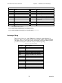
Revision
A
B
C
D
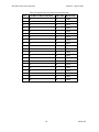
Revision Record
Description
Manual Released
Added ThinCLIENT touch screen calibration instructions
Added Lithium Battery Replacement section
Name change, correct where applicable with document
Date
8/04
10/04
1/06
4/07
Part Number 143243 (D)
Trademark Information
Xycom and Xycom Automation are trademarks of Xycom Automation, L.L.C.
Xycom Automation, L.L.C. now is referred to as Pro-face through a D.B.A. The Pro-face name and logo will replace
the Xycom name and logo on all documents where possible.
Pro-face is a trademark of Digital Electronics Corporation.
Brand or product names may be registered trademarks of their respective owners. Windows is a registered
trademark of Microsoft Corporation in the United States and other countries..
Copyright Information
This document is copyrighted by Xycom Automation, L.L.C. (Xycom) and shall not be reproduced or copied without
expressed written authorization from Xycom Automation, L.L.C.
The information contained within this document is subject to change without notice. Pro-face does not guarantee the
accuracy of the information
United States FCC Part 15, Subpart B, Class A EMI Compliance Statement:
This equipment has been tested and found to comply with the limits for a Class A digital device, pursuant to part 15
of the FCC Rules. These limits are designed to provide reasonable protection against harmful interference when the
equipment is operated in a commercial environment. This equipment generates, uses, and can radiate radio
frequency energy and, if not installed and used in accordance with the instruction manual, may cause harmful
interference to radio communications. Operation of this equipment in a residential area is likely to cause harmful
interference, in which case the user will be required to correct the interference at the user’s expense.
For European Users – WARNING:
This is a Class A product. In a domestic environment this product may cause radio interference in which case the
user may be required to take adequate measures.
INSTALLATION: Electromagnetic Compatibility WARNING
The connection of non-shielded equipment interface cables to this equipment will invalidate FCC EMI and European
Union EMC compliance and may result in electromagnetic interference and/or susceptibility levels which are in
violation of regulations which apply to the legal operation of this device. It is the responsibility of the system
integrator and/or user to apply the following directions that relate to installation and configuration:
All interface cables must include shielded cables. Braid/foil type shields are recommended. Communication cable
connectors must be metal, ideally zinc die-cast backshell types, and provide 360-degree protection about the
interface wires. The cable shield braid must be terminated directly to the metal connector shell; ground drain wires
alone are not adequate.
Protective measures for power and interface cables as described within this manual must be applied. Do not leave
cables connected to unused interfaces or disconnected at one end. Changes or modifications to this device not
expressly approved by the manufacturer could void the user’s authority to operate the equipment.
EMC compliance is, in part, a function of PCB design. Third party add-on AT/XT peripheral PCB assemblies installed
within this apparatus may void EMC compliance. FCC/CE compliant PCB assemblies should always be used where
possible. Pro-Face can accept no responsibility for the EMC performance of this apparatus after system
integrator/user installation of PCB assemblies not manufactured and/or expressly tested and approved for
compliance by Pro-Face. It is the responsibility of the system integrator/user to ensure that installation and operation
of such devices does not void EMC compliance.
i
143243(D)
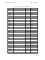
Table of Contents
CHAPTER 1 – SYSTEM OVERVIEW..........................................................................................................................1
Standard Features ......................................................................................................................................................1
Optional Features....................................................................................................................................................2
Front Panel .............................................................................................................................................................3
Back Panel............................................................................................................................................................10
Power Panels ........................................................................................................................................................11
Unpacking the System .............................................................................................................................................12
Quick Start-up .........................................................................................................................................................13
CHAPTER 2 – INSTALLATION.................................................................................................................................14
Installation Overview ..............................................................................................................................................14
System Cutout Dimensions......................................................................................................................................16
3308T Cutout Dimensions....................................................................................................................................16
3308KP Cutout Dimensions .................................................................................................................................17
3310T/3312T Cutout Dimensions ........................................................................................................................18
3310KP(T)/3312KP(T) Cutout Dimensions.........................................................................................................19
1401 Drill Pattern .................................................................................................................................................20
Power Management .................................................................................................................................................21
System Power .......................................................................................................................................................21
Excessive Heat......................................................................................................................................................21
Electrical Noise ....................................................................................................................................................21
Line Voltage Variation .........................................................................................................................................22
Power Supply........................................................................................................................................................22
Creating a Power Cable ........................................................................................................................................23
Installing Internal Hardware Options ......................................................................................................................25
DRAM Dual Inline Memory Modules (SODIMMs) ............................................................................................25
PC/104 Boards......................................................................................................................................................25
Installing External Hardware Options .....................................................................................................................26
External Floppy Drive ..........................................................................................................................................26
Using a Touch Screen..............................................................................................................................................27
Calibrating the Touch Screen ...............................................................................................................................28
Custom Logo ...........................................................................................................................................................29
Creating Customized Keypad Inserts ......................................................................................................................29
3308KP Keypad Inserts........................................................................................................................................30
3310KP/3312KP Keypad Inserts..........................................................................................................................33
Hazardous Location Installations ............................................................................................................................36
Definitions ............................................................................................................................................................37
Group Ratings.......................................................................................................................................................39
Enclosures ............................................................................................................................................................39
Power Switch........................................................................................................................................................39
Cable Connections................................................................................................................................................40
Communication Cable Interfaces..........................................................................................................................40
Hazardous Locations Control Drawing ................................................................................................................41
Operation and Maintenance..................................................................................................................................42
Safety Agency Approval.......................................................................................................................................42
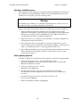
CHAPTER 3 – KEYPAD FUNCTIONALITY ..............................................................................................................43
Control Keypad .......................................................................................................................................................43
3308KP.................................................................................................................................................................43
3310KP(T)/3312KP(T) ........................................................................................................................................43
ii
143243(D)
3300 Series Flat Panel Industrial PC
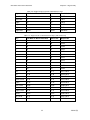
Table of Contents
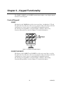
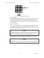
Numeric Keypad......................................................................................................................................................45
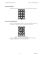
Cursor Control Keypad............................................................................................................................................45
Function/Alpha Keypads .........................................................................................................................................46
3308KP.................................................................................................................................................................46
3310KP.................................................................................................................................................................47
CHAPTER 4 – KEYPAD UTILITY .............................................................................................................................48
Loading the Keypad Utility .....................................................................................................................................48
Using the Keypad Utility.........................................................................................................................................48
Startup .....................................................................................................................................................................49
Main Menu ..............................................................................................................................................................50
Exit .......................................................................................................................................................................50
Files Menu ............................................................................................................................................................50
Macros Menu........................................................................................................................................................51
Upload Menu........................................................................................................................................................54
Download Menu ...................................................................................................................................................54
Utilities Menu.......................................................................................................................................................54
Utility Batch Mode..................................................................................................................................................55
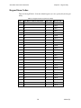
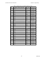
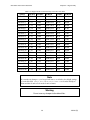
Keypad Scan Codes.................................................................................................................................................56
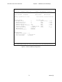
CHAPTER 5 – MOTHERBOARD AND BIOS SETUP ...............................................................................................64
Motherboard and BIOS Setup Overview.................................................................................................................64
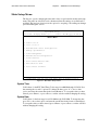
Main Setup Menu ....................................................................................................................................................65
System Time .........................................................................................................................................................65
System Date..........................................................................................................................................................65
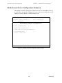
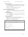
Motherboard Device Configuration Submenu.........................................................................................................66
Drive Configuration Submenu.................................................................................................................................67
IDE Configuration ................................................................................................................................................67
Boot Order Configuration.....................................................................................................................................68
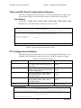
Super I/O Configuration Submenu ..........................................................................................................................68
Serial Port Configuration......................................................................................................................................68
Parallel Port Configuration...................................................................................................................................68
Video and Flat Panel Configuration Submenu ........................................................................................................69
Video Memory......................................................................................................................................................69
PCI Configuration Submenu....................................................................................................................................69
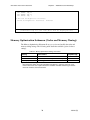
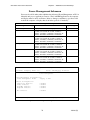
Memory Optimization Submenu (Cache and Memory Timing) ..............................................................................70
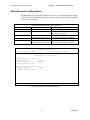
Miscellaneous Configuration...................................................................................................................................73
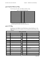
3300 System Memory Map .....................................................................................................................................74
3300 I/O Map ..........................................................................................................................................................74
Interrupt Map...........................................................................................................................................................75
DMA Mapping ........................................................................................................................................................76
3300
PCI Devices ..............................................................................................................................................76
3300 Base Addresses in 5530A...............................................................................................................................77
CHAPTER 6 – MAINTENANCE ................................................................................................................................78
Preventive Maintenance ..........................................................................................................................................78
Pro-face Recommended Hard Drive Preventive Maintenance ................................................................................78
Replacing the Fuse ..................................................................................................................................................79
System Battery Replacement ...................................................................................................................................79
Product Repair Program ..........................................................................................................................................82
Chemical Compatibility...........................................................................................................................................84
Compatible Lubricants..........................................................................................................................................85
Compatible Cleaning Agents ................................................................................................................................86
Non-compatible Cleaning Agents.........................................................................................................................86
iii
143243 (D)
3300 Series Flat Panel Industrial PC
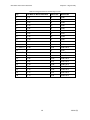
Table of Contents
CHAPTER 7 – TROUBLESHOOTING.......................................................................................................................87
Diagnostic Tests ......................................................................................................................................................87
Preparing for the Tests..........................................................................................................................................87
Set BIOS to Defaults ............................................................................................................................................88
Running the Tests .................................................................................................................................................89
Reinstalling Operating Systems...............................................................................................................................90
MS-DOS Reinstallation ......................................................................................................................................90
Windows 98 Reinstallation.................................................................................................................................91
Windows NT Reinstallation ...............................................................................................................................91
Windows 2000 Reinstallation.............................................................................................................................91
Installing Drivers .....................................................................................................................................................92
Ethernet Drivers....................................................................................................................................................92
Touch Screen Drivers ...........................................................................................................................................92
Video Drivers .......................................................................................................................................................93
Miscellaneous Drivers ..........................................................................................................................................93
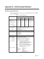
APPENDIX A– TECHNICAL SPECIFICATIONS.......................................................................................................94
Hardware Specifications..........................................................................................................................................94
Environmental Specifications..................................................................................................................................95
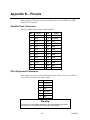
APPENDIX B – PINOUTS .........................................................................................................................................96
Parallel Port Connector ...........................................................................................................................................96
PS/2 Keyboard Connector .......................................................................................................................................96
Mouse Port Connector.............................................................................................................................................97
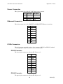
External Floppy Drive Connector............................................................................................................................97
Power Connector .....................................................................................................................................................98
Ethernet Connector..................................................................................................................................................98
COM1 Connector ....................................................................................................................................................98
RS-232 Connector ................................................................................................................................................98
RS-485 Connector ................................................................................................................................................98
COM2 Connector ..................................................................................................................................................100
APPENDIX C – LPG1 AND JUMPER SETTINGS ..................................................................................................101
3300 Motherboard LPG1 and Jumper Settings .....................................................................................................101
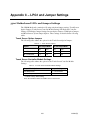
Touch Screen Option Jumpers............................................................................................................................101
Touch Screen Controller Module Settings..........................................................................................................101
H8 Keyboard Controller Settings .......................................................................................................................102
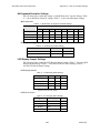
LCD Display Jumper Settings ............................................................................................................................102
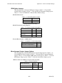
Inverter Option Jumpers .....................................................................................................................................103
COM Option Jumpers.........................................................................................................................................104
Miscellaneous System Jumper Options ..............................................................................................................104
APPENDIX D DOS VIDEO MODES ........................................................................................................................106
APPENDIX E SETTING UP YOUR OPENCLIENT 3300 AS A THINCLIENT ........................................................109
APPENDIX F 3300 SERIES THINCLIENT TOUCH SCREEN CALIBRATION INSTRUCTIONS ...........................111
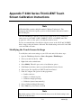
Modifying the Touch Screen Settings ...................................................................................................................111
Calibrating the Touch Screen ................................................................................................................................112
iv
143243 (D)
Chapter 1 – System Overview
The 3308T, 3308KP, 3310T, 3310KP(T), 3312T and 3312KP(T) Industrial PCs combine
a PC/AT computer with a flat-panel display to offer a powerful, fanless, compact
package for the factory floor and other harsh environments.
The units feature an open architecture to meet a variety of applications requiring both a
PC and a durable industrial enclosure. The units’ front panels – sealed to NEMA
4/4X/12 – are protected by an impact-resistant shield.
The units’ processor board combines all the functions of a PC/AT-compatible computer
on an industrially hardened circuit board.
A screenless version is also available. The 1401 offers the same computing power in a
small, rugged, fanless enclosure without an integrated display.
Standard Features
The units offer the following standard features:
3.3-inch mounting depth (3308 units)
3.5-inch mounting depth (3310 and 3312 units)
Flat-panel displays
•
8.4-inch TFT flat-panel color display, 640x480 VGA (3308 units)
•
10.4-inch TFT flat-panel color display 640x480 VGA (3310 units)
•
12.1-inch TFT flat panel color display, 800x600 SVGA (3312 units)
LPG1 motherboard, with features including:
•
300 MHz Geode GX1 processor
•
144-pin SODIMM site support (128 or 256 MB of memory)
•
PCI 64-bit video controller, shared video RAM up to 4 MB
•
PCI-bus IDE controller
•
Communication ports
COM1 – 9-pin RS-232 or 9-pin RS-485
COM2 – 25-pin RS-232
Two USB 1.1 ports
One parallel port
PS/2 mouse and keyboard ports
•
One 10BASE-T/100 BASE-TX Ethernet controller
•
Socket for removable CompactFlash® (Type I)
•
Disk on Chip Site (DOC 2000)
•
20 GB (minimum) hard drive
1
143243(D)
3300 Series Flat Panel Industrial PC
•
Chapter 1 – Introduction
Flash BIOS
PC/104 expansion site, allowing you to stack two PC/104 boards
AC input power
External floppy connector (FOR USE WITH 9000-EXF)
Diagnostic LEDs: Power, Disk, COM and Input (3308T, 3310T, and 3312T)
MS-DOS® (MS-DOS® is not included if you order Windows® 98, Windows® NT,
or Windows® 2000)
NEMA 4/4X/12 sealed front panel
Class I, Division 2 Hazardous Location approval (not available on units with
fieldbus or control options installed)
The 3308KP, 3310KP and 3312KP also include function, control, numeric, alpha,
and cursor control keypads.
Optional Features
The following optional features are available:
Windows® 98, Windows® NT, or Windows® 2000 pre-installed
External floppy drive
24-volt DC power supply
The figures and tables on the next several pages illustrate the internal and external
components on the front and back panels of the units to help you locate the features of
the 3300 series and 1401 node box.
2
143243 (D)
3300 Series Flat Panel Industrial PC
Chapter 1 – Introduction
Front Panel
The 3308/10/12 units come with a NEMA 4/4X/12 sealed front panel. The panel protects
the system’s interior when the system is properly panel mounted in an enclosure.
The 1401 is generally mounted on an inside wall of an enclosure. 1401 installation
instructions are on page 20.
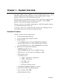
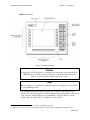
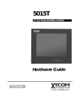
3308T/3310T/3312T Front Panel
Figure 1-1. 3308T/3310T/3312T Front Panel
Caution
Leaving your TFT LCD display on constantly can result in temporary image retention
(TIR). TIR can be avoided by using a screen saver, enabling the idle/doze timeout
feature, or by turning off the display when it is not in use.
3
143243 (D)
3300 Series Flat Panel Industrial PC
Chapter 1 – Introduction
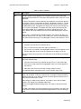
Table 1-1. 3308T/3310T/3312T Front Panel Features
Feature
Description
Front Panel
The front panel has four components: a display; strengthened glass
covering the display; a frame in which the display and the glass are
mounted; and the polyester overlay attached to both the glass and the
frame
The 3308T has an 8.4-inch TFT active matrix color LCD flat-panel display.
The 3310T has a 10.4-inch TFT active matrix color LCD flat-panel display.
The 3312T has a 12.1-inch TFT active matrix color LCD flat-panel display.
The strengthened glass covering the display is intended to withstand
normal operating conditions. In the event of damage to the glass, the
overlay will protect the user from any glass shards.
For more information abut the frame or the overlay, see Chapter 5 –
Troubleshooting.
Diagnostic LEDs
Brightness
Control Keys
Power Green when there is power to the unit.
Disk
Green when the computer module is accessing the disk drive.
COM
Green when there is communication on one of the computer
module’s serial ports.
Input
Green when the unit has a touch screen. This LED gets brighter
when it detects a touch input.
These two keys control the brightness of the monitor. The left key
decreases brightness; the right key increases brightness.
4
143243 (D)
3300 Series Flat Panel Industrial PC
Chapter 1 – Introduction
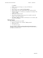
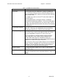
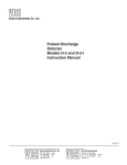
3308KP Front Panel
Figure 1-2. 3308KP Front Panel
Caution
Leaving your TFT LCD display on constantly can result in temporary image retention
(TIR). TIR can be avoided by using a screen saver, enabling the idle/doze timeout
feature, or by turning off the display when it is not in use.
Note
Refer to Chapter 3 for information on using the keypads, and Chapter 4 for information
on reprogramming the keys.
The 3308KP features function keys on either side of the flat panel display (F1-F12),
function keys below the display (F13-F20), a numeric keypad, window keys, and a cursor
control keypad. All keypad keys are reprogrammable1, except the F/A key, and all
function keys are relegendable2. See Chapter 4 for more details.
1
2
All keypad keys can be programmed to perform any function necessary.
You are able to create your own, custom keypad inserts to reflect any reprogramming you may have done.
5
143243 (D)
3300 Series Flat Panel Industrial PC
Chapter 1 – Introduction
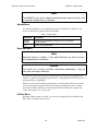
Table 1-2. 3308KP Front Panel Features
Feature
Description
Front Panel
The front panel has four components: a display; strengthened
glass covering the display; a frame in which the display and the
glass are mounted; and the polyester overlay attached to both the
glass and the frame.
The 3308KP ships with an 8.4-inch TFT active matrix color LCD
flat-panel display.
The strengthened glass covering the display is intended to
withstand normal operating conditions. In the event of damage to
the glass, the overlay will protect the user from any glass shards.
Function/Alpha Keypads
Control/Alpha Keypad
For more information abut the frame or the overlay, see Chapter 6
– Maintenance
The keypads provide function keys F1-F20, as well as uppercase
letters A-T. These keys are relegendable (refer to theCreating
Customized Keypad Inserts section for more information).
This keypad provides the CTRL, SHIFT, INS, ALT, TAB, DEL, F/A,
and + keys, as well as the uppercase letters U-Z. All the
keys are relegendable, except the F/A, SPACE, and + keys.
SPACE,
The F/A key toggles the keypads between function and alpha
mode. When the F/A key is not pressed, the keypads are in
function mode. When you press and hold the F/A key, the
keypads are in alpha mode (refer to the Control Keypad section to
determine the location of the alpha characters).
You can also use the F/A key to adjust brightness on the flat-panel
display. To do this, hold down the F/A key while pressing a cursor
control key. The Up and Right control keys increase brightness;
the Down and Left control keys decrease brightness.
Numeric Keypad
This keypad provides numbers 0-9, as well as a decimal point
and a minus sign.
Cursor Control Keypad
This keypad controls cursor movement. It also provides
brightness control when used in conjunction with the F/A key (see
above).
6
143243 (D)
3300 Series Flat Panel Industrial PC
Chapter 1 – Introduction
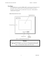
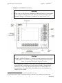
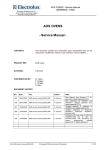
3310KP(T) and 3312KP(T) Front Panel
Warning
Never connect or disconnect the communication cables in Hazardous Locations while
power is applied at either end of the cable. This may result in an incendiary spark.
Permanent damage to the workstation communication components may occur.
Figure 1-3. 3310KP(T)/3312KP(T) Front Panel
Caution
Leaving your TFT LCD display on constantly can result in temporary image retention
(TIR). TIR can be avoided by using a screen saver, enabling the idle/doze timeout
feature, or by turning off the display when it is not in use.
The 3310KP(T) and 3312KP(T) feature function keys on either side of the flat panel
display (PF1-PF12), function keys below the display (F1-F20), a numeric keypad,
window keys, a cursor control keypad, and a keyboard port. All keypad keys are
reprogrammable3, except the F/A key, and all function keys are relegendable4. See
Chapter 4 for more details.
3
4
All keypad keys can be programmed to perform any function necessary.
You are able to create your own, custom keypad inserts to reflect any reprogramming you may have done.
7
143243 (D)
3300 Series Flat Panel Industrial PC
Chapter 1 – Introduction
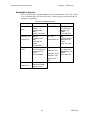
Table 1-3. 3310KP(T)/3312KP(T) Front Panel Features
Feature
Description
Front Panel
The front panel has four components: a display; strengthened glass covering the
display; a frame in which the display and the glass are mounted; and the
polyester overlay attached to both the glass and the frame.
The 3310KP(T) has a 10.4-inch TFT active matrix color LCD flat-panel display.
The 3312KP(T) has a 12.1-inch TFT active matrix color LCD flat-panel display.
The 3310KP(T) and 3312KP(T) also have optional touch screens.
The strengthened glass covering the display is intended to withstand normal
operating conditions. In the event of damage to the glass, the overlay will protect
the user from any glass shards.
For more information abut the frame or the overlay, see Chapter 6 –
Maintenance.
PF/Function/
Alpha Keypads
The keypads provide function keys F1-F20, PF keys 1-12 (PF keys 7-12 also
include punctuation symbols), as well as uppercase letters A-Z. These keys are
relegendable (refer to Creating Customized Keypad Inserts on page 29).
Control Keypad
This keypad provides the CTRL, SHIFT, INS, ALT, TAB, DEL, F/A, SPACE, and + keys.
All the keys are relegendable, except the F/A, SPACE, and + keys. These keys
work the same as they do on a keyboard.
The F/A key toggles the keypads between function and alpha mode. When the
F/A key is not pressed, the keypads are in function mode. When you press and
hold the F/A key, the keypads are in alpha mode (refer to Figure 1-3 to determine
the location of the alpha characters).
You can also use the F/A key to adjust brightness on the flat-panel display. To do
this, hold down the F/A key while pressing a cursor control key. The Up and Right
control keys increase brightness; the Down and Left control keys decrease
brightness.
Numeric Keypad
This keypad provides numbers 0-9, as well as a decimal point and a minus sign.
Cursor Control
Keypad
This keypad controls cursor movement.
Keyboard Port
(front access)
The 3310KP(T) and 3312KP(T) provide both front- and rear-accessible PS/2
keyboard connectors. The front-accessible connector is located on the lower right
side of the front panel. The rear accessible connector is located on the side of
the unit refer to Figure 1-4 to determine the location of the keyboard port).
Warning: To maintain a safe condition, do not use an external keyboard on
these ports when the unit is operating in a Hazardous Location.
Warning
In order to maintain a safe condition, never use an external keyboard connected to rear
ports when the unit is operating in a Hazardous Location. Use of the front panel
keyboard port is safe only if the control drawing criteria is satisfied as indicated on the
control drawing on page 41 and if the device is approved for use in the classified
Hazardous Location.
8
143243 (D)
3300 Series Flat Panel Industrial PC
Chapter 1 – Introduction
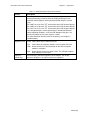
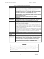
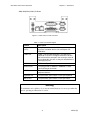
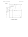
3308/3310/3312/1401 I/O Panel
Figure 1-4. 3300 series and 1401 I/O Panel
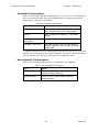
Table 1-4. 3300 I/O Panel Description
Feature
Description
Parallel Port
(LPT1)
This port provides a standard PC-compatible interface
to printers and other devices, like a backpack CDROM drive.
COM1 Port
COM1 is RS-232/485 compatible. The lower 9-pin
connector is RS-232. The upper connector is the RS485 version of the same port. You can only use one of
these connectors at a time, as they are attached to the
same physical port.
COM2 Port
COM2 is a 25-pin RS-232 connector.
Ethernet Port
This port provides a 10BASE-T/100BASE-TX autosensing Ethernet connection.
USB Ports
These two USB 1.1 ports are available for various
peripheral devices.
Keyboard Port
This port allows you to attach a PS/2-style keyboard.
Mouse Port
This port allows you to attach a PS/2-style mouse.
Warning
To maintain a safe condition, do not use an external keyboard or mouse port when the
unit is operating in a Hazardous Location.
9
143243 (D)
3300 Series Flat Panel Industrial PC
Chapter 1 – Introduction
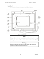
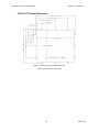
Back Panel
The picture below illustrates the back panel of the 3300 and 1401 units.
Figure 1-5. 3308 Back Panel
Note
While the 3308 model has only 8 mounting studs, the 3310 & 3312 have 12 mounting
studs. The 1401 has 4 mounting holes for wall or panel mounting. All other aspects of
the back panel are the same on other models.
Warning
You must disconnect the power cable, floppy cable, and any other external cables
connected to the unit, before removing the back cover.
10
143243 (D)
3300 Series Flat Panel Industrial PC
Chapter 1 – Introduction
Table 1-5. Back Panel Features
Feature
Description
Back Cover
The back cover has five tabs that slide into corresponding
slots on the display carrier, and three screws that secure
the cover to the unit.
External Floppy Disk Drive
(optional)
You can install an external floppy disk drive to the back of
the unit. It connects to the floppy connector on the bottom
of the unit.
Panel Mounting Studs
There are studs on the back of the unit for panel
mounting. The 3308 unit has 8 mounting studs; the 3310
and 3312 units have 12 mounting studs. The 1401
mounts with 4 mounting holes.
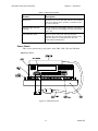
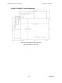
Power Panels
This section describes the power panels on the 3308, 3310, 3312 and 1401 units.
3308 Power Panel
Figure 1-6. 3308 Power Panel
11
143243 (D)
3300 Series Flat Panel Industrial PC
Chapter 1 – Introduction
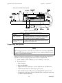
3310, 3312, and 1401 Power Panels
Figure 1-7. 3310/12 Power Panel
Table 1-6. 3308/10/12 & 1401 Power Panel Features
Feature
Description
Power Connector
The power receptacle is a three-pin connector. Refer
to the Hazardous Location Installations section later in
this chapter for special installation instructions.
External Floppy Drive
Connector
The 26-pin floppy drive connector lets you connect an
optional external floppy drive.
Unpacking the System
Note
The following list pertains to a basic PC-only system. If a Pro-face/Xycom OpenHMI
or OpenCNTRL workstation has been purchased, a more complete packing list may be
found in a separate Quickstart manual.
When you remove the system from its box, verify that you have the parts listed below.
Save the box and inner wrapping in the event you need to reship the unit.
3308T, 3308KP, 3310T, 3310KP(T), 3312T, 3312KP(T), or 1401 unit
Documentation kit:
•
Power connector
•
Recovery CD-ROM
•
Eight 8-32 hex nuts (3308 series) or twelve 10-32 hex nuts (3310/12 series)
•
Cable clamp and screw (for strain relief of power cord)
•
Four standoffs and four 4-40 screws for mounting PC/104 expansion cards
•
Documentation and Support Library CD-ROM, which contains this manual and
all drivers required by the unit.
12
143243 (D)
3300 Series Flat Panel Industrial PC
Chapter 1 – Introduction
Quick Start-up
Note
The following steps pertain to a basic PC-only system. If a Pro-face/Xycom OpenHMI
or OpenCNTRL workstation has been purchased, more complete instructions are
included in a separate Quickstart manual.
This section provides the steps to get the system operating, without explaining system
capabilities and options.
Warning
Disconnect the power cord before making any adjustments to the inside or outside of
the computer.
Perform the following steps to prepare the system for use:
1. Attach optional equipment following the instructions in Chapter 2.
2. Attach the power cord from the power receptacle to a properly grounded 100-240
VAC, 50-60 Hz outlet. (See Creating a Power Cable on page 23.)
3. On a 1401 unit, attach an external CRT or flat-panel display.
4. Turn on power to the unit. The system will boot-up into the operating system.
5. On the 3308T, 3310T, and 3312T units, adjust the brightness by using the brightness
keys on the front panel. On the 3308KP, 3310KP(T), 3312KP(T) units, adjust the
brightness by pressing and holding the “F/A” key, and then pressing the left or right
arrow key to increase or decrease brightness.
6. Install application software via the external floppy or the network.
13
143243 (D)
Chapter 2 – Installation
This chapter outlines installation procedures, including the system cutout dimensions,
and details the power management for the 3308, 3310, 3312, and 1401 units. It also
includes installation instructions for internal and external hardware options; touch screen
usage and calibration; and Hazardous Locations installation guidelines. You can learn
how to create a customized logo and keypad inserts in this chapter as well.
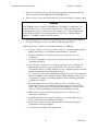
Installation Overview
Warning
For installation in Hazardous Locations, review the Hazardous Location Installations
section in this chapter before startup.
The rugged design of the 3300 unit allows it to be installed in most industrial
environments. The system is generally placed in a NEMA 4/4X/12 enclosure to protect
against contaminants such as dust, and moisture. Metal enclosures also help minimize
the effects of electromagnetic radiation that nearby equipment can generate. The 1401
can be wall mounted or mounted on a shelf (see Figure 2-5 for details).
Read the following sections carefully to be sure that you are complying with all the
safety requirements.
1. Select a NEMA rated enclosure and place the unit to allow easy access to the system
ports (see other sections in this chapter and Appendix A).
•
To assure a NEMA 4 seal choose an approved enclosure that has a 14-gauge
(0.075 in/1.9 mm thick steel or 0.125 in/3.2 mm thick aluminum) front face.
•
Be sure to account for the unit’s depth when choosing the depth of the enclosure.
2. Create a cutout in the enclosure (see Figure 2-1 through Figure 2-5 in System Cutout
Dimensions).
•
Be sure to place the unit at a comfortable working level
•
Make sure the area around the cutout is clean and free from metal burrs
3. Mount the unit in an upright position and properly secure the unit into the panel.
•
Tighten the twelve (8 on a 3308T/KP) #10 nuts to 25 inch-pounds (2.8 Newtonmeters / 28Kgf cm).
4. Construct a power cable following the instructions in Creating a Power Cable on
page 23 in this chapter.
14
143243(D)
3300 Series Flat Panel Industrial PC
Chapter 2 – Installation
5. Attach one end of the power cord to the power receptacle on the unit and the other
end to a properly grounded 100-240 VAC, 50-60 Hz outlet.
6. Turn on power to the system. The system will boot-up the installed operating system.
Caution
Your 3300 unit does not contain a CD-ROM drive. We highly recommend that you
create a backup set of boot floppy disks for Windows® or DOS operating system
immediately upon receipt of your system. The backup set of boot floppy disks will be
needed in the event that your operating system ever needs to be reinstalled. Refer to
Chapter 7 – Troubleshooting for more information.
7. Install the application software via external floppy drive, parallel port CD-ROM, or
the network. Software can also be loaded via Type I Compact Flash®.
Additional aspects to take into account when mounting your 3300 unit:
Consider locations of accessories such as AC power outlets and lighting (interior
lighting and windows) for installation and maintenance convenience
Prevent condensation by installing a thermostat-controlled heater or air
conditioner
To allow for maximum cooling, select an adequate sized enclosure and avoid
obstructing the airflow
Place any fans or blowers close to the heat-generating devices. If using a fan,
make sure that outside air is not brought into the enclosure unless a fabric or
other reliable filter is used. This filtration prevents conductive particles and other
harmful contaminants from entering the enclosure.
Do not select a location near equipment that generates excessive electromagnetic
interference (EMI) or radio frequency interface (RFI). Examples of these types
of equipment are: high power welding machines; induction heating equipment;
and large motor starters.
Place incoming power line devices (such as isolation or constant voltage
transformers, local power disconnects, and surge suppressers) away from the
system. The proper location of incoming line devices keeps power wire runs as
short as possible and minimizes electrical noise transmitted to the unit.
Make sure the location does not exceed the unit’s shock, vibration, and
temperature specifications
Install the unit in the rack or panel in such a way as to ensure that it does not
cause a hazard from uneven mechanical loading
Incorporate a readily-accessible disconnect device in the fixed wiring on
permanently connected equipment
Avoid circuit overloading of the supply circuit
15
143243 (D)
3300 Series Flat Panel Industrial PC
Chapter 2 – Installation
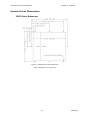
System Cutout Dimensions
3308T Cutout Dimensions
Figure 2-1. 3308T System Cutout Dimensions
Note : All dimensions in inches [mm]
16
143243 (D)
3300 Series Flat Panel Industrial PC
Chapter 2 – Installation
3308KP Cutout Dimensions
Figure 2-2. 3308KP System Cutout Dimensions
Note : All dimensions in inches [mm]
17
143243 (D)
3300 Series Flat Panel Industrial PC
Chapter 2 – Installation
3310T/3312T Cutout Dimensions
Figure 2-3. 3310/12T System Cutout Dimensions
Note : All dimensions in inches [mm]
18
143243 (D)
3300 Series Flat Panel Industrial PC
Chapter 2 – Installation
3310KP(T)/3312KP(T) Cutout Dimensions
Figure 2-4. 3310/12KP System Cutout Dimensions
Note : All dimensions in inches [mm]
19
143243 (D)
3300 Series Flat Panel Industrial PC
Chapter 2 – Installation
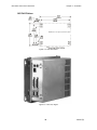
1401 Drill Pattern
All dimensions are expressed in inches (mm).
Figure 2-5. 1401 Drill Pattern
Figure 2-6. 1401 Unit, Angled
20
143243 (D)
3300 Series Flat Panel Industrial PC
Chapter 2 – Installation
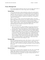
Power Management
The following paragraphs explain the system power, the power supply, and the effects of
excessive heat, electrical noise, and line voltage variation of the 3300 unit.
System Power
Using isolation transformers on the incoming AC power line to the system is always a
good practice. An isolation transformer is especially desirable in cases in which heavy
equipment is likely to introduce noise onto the AC line. The isolation transformer can
also serve as a step-down transformer to reduce the incoming line voltage to a desired
level. The transformer should have a sufficient power rating (units of volt-amperes) to
supply the load adequately.
Proper grounding is essential to all safe electrical installations. Refer to the relevant
federal, state/provincial, and local electric codes, which provide data such as the size and
types of conductors, color codes and connections necessary for safe grounding of
electrical components. The code specifies that a grounding path must be permanent (no
solder), continuous, and able to safely conduct the ground-fault current in the system
with minimal impedance (minimum wire required is 18 AWG, 1 mm).
Observe the following procedures:
Separate ground wires (P.E. or Protective Earth) from power wires at the point of
entry to the enclosure. To minimize the ground wire length within the enclosure,
locate the ground reference point near the point of entry for the plant power supply.
All electrical racks or chassis and machine elements should be Earth Grounded in
installations where high levels of electrical noise can be expected. The rack/chassis
should be grounded with a ground rod or attached to a nearby Earth structure such as
a steel support beam. Connect each different apparatus to a single Earth Ground
point in a “star” configuration with low impedance cable. Scrape away paint and
other nonconductive material from the area where a chassis makes contact with the
enclosure. In addition to the ground connection made through the mounting bolt or
stud, use a one-inch metal braid or size #8 AWG wire to connect between each
chassis and the enclosure at the mounting bolt or stud.
Excessive Heat
The systems withstand temperatures from 0º to 50º C. They are cooled by convection, in
which a vertical column of air is drawn in an upward direction over the surface of its
components. To keep the temperature in range, the cooling air at the base of the system
must not exceed 50° C. Allocate proper spacing between internal components installed in
the enclosure.
When the air temperature is higher than the specified maximum in the enclosure, use a
fan or air conditioner to lower the temperature.
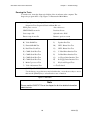
Electrical Noise
Electrical noise is seldom responsible for damaging components, unless extremely high
energy or high voltage levels are present. However, noise can cause temporary
malfunctioning, which can result in hazardous machine operation in certain applications.
Noise may be present only at certain times, may appear at widespread intervals, or in
some cases may exist continuously.
21
143243 (D)
3300 Series Flat Panel Industrial PC
Chapter 2 – Installation
Noise commonly enters through input, output, and power supply lines, and may also be
coupled through the capacitance between these lines and the noise signal carrier lines.
This usually results from the presence of high voltage or long, close-spaced conductors.
When control lines are closely spaced with lines carrying large currents, the coupling of
magnetic fields can also occur. Use shielded cables to help minimize noise. Potential
noise generators include switching components, relays, solenoids, motors, and motor
starters.
Refer to the relevant Federal, State/Provincial, and local electric codes, which provide
data such as the size and types of conductors, color codes and connections necessary for
safe grounding of electrical components. It is recommended that high- and low-voltage
cabling be separated and dressed apart. In particular, AC cables and switch wiring should
not be in the same conduit with all communication cables.
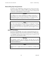
Line Voltage Variation
The power supply section of the unit is built to sustain line fluctuations of 90-250 VAC
and still allow the system to function within its operating margin. As long as the
incoming voltage is adequate, the power supply provides all the logic voltages necessary
to support the processor, memory, and I/O.
When the installation is subject to unusual AC line variations, use a constant voltage
transformer to prevent the system from shutting down too often. However, a first step
toward the solution of the line variations is to correct any possible feed problem in the
distribution system. If this correction does not solve the problem, use a constant voltage
transformer.
The constant voltage transformer stabilizes the input voltage to the systems by
compensating for voltage changes at the primary in order to maintain a steady voltage at
the secondary. When using a constant voltage transformer, check that the power rating is
sufficient to supply the unit.
Power Supply
The standard systems ship with an AC power supply; a 24 VDC power supply is
optional. This section provides specifications for both AC and DC power supplies.
AC Power Supply
The AC power supply provides 100-240 VAC, 50-60 Hz (wide-ranging), 1 A maximum.
This power supply typically consumes approximately 22 W, with no option boards
installed.
DC Power Supply
The DC power supply accepts 18 to 30 VDC input voltage for applications requiring DC
input power. Electrical specifications for the power supply are 18 to 30 VDC, 3.6 A
maximum.
22
143243 (D)
3300 Series Flat Panel Industrial PC
Chapter 2 – Installation
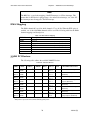
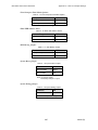
Expansion Power
The available power from both the AC and DC power supplies is listed below:
Table 2-1. Available Expansion Power
Voltage
LPG1 Available Current
+5 V
+12 V
- 12 V
2.0 A
1.0 A
0.4 A
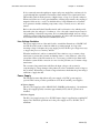
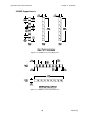
Creating a Power Cable
This section describes how to create both an AC and a DC power cable.
AC Power Cable
You must create an AC power cable to furnish power to units with AC power supplies.
You will need the following materials:
A three-position power connector (supplied)
A braid/foil shielded power cable with three 18 (1.0 mm), 16 (1.3 mm), or 14 (1.6
mm) AWG solid or stranded copper wire, rated 80º C or better.
Perform the following steps to create the cable:
1. Cut the wire cable to the desired length.
2. Strip 0.25 in (6 mm) of insulation from the end of the conductor wire. No bare
wire should be exposed when the cable is connected to the workstation.
3. Tin the wire ends with solder if using stranded wire. This will keep the wire from
fraying.
Warning
When inserting the wire ends of the power cable into the block plug, be sure there is no
exposed wire. Trim the wire ends of the cable or cut a new cable if necessary.
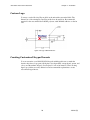
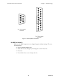
4. Insert the three wire ends of the power cable into the three holes of the block plug.
Insert the Protective Earth GND ground, L1, and L2/N wires into the
corresponding holes, as shown in Figure 2-7. Be sure that no bare wires are
exposed.
Figure 2-7. AC Power Connector
5. Tighten the three screws above the wires to hold them firmly in place.
23
143243 (D)
3300 Series Flat Panel Industrial PC
Chapter 2 – Installation
Warning
Never tighten the three screws of the block plug when the cable is connected to a
power source. The screws are conductive and have full contact with the cable wire.
6. Use a cable clamp and #6-32 screw (provided) to secure and provide strain relief to
the power cable. When installing the power cable to the unit, use the securing
screws on each side of the plug. This strain relief is mandatory for Hazardous
Locations compliance.
Warning
Be sure to completely loosen the two securing screws on the plug when disconnecting
the power cord from the unit.
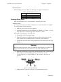
DC Power Cable
You must create a DC power cable to supply power to units with DC power supplies.
You will need the following materials:
A three-position power connector (supplied)
A braid/foil shielded power cable with three 18 (1.0 mm), 16 (1.3 mm), or 14 (1.6
mm) AWG solid or stranded copper wire, rated 80º C or better.
Perform the following steps to create the cable:
1. Cut the wire cable to the desired length.
2. Strip 0.25 in (6 mm) of insulation from the end of the conductor wire. No bare
wire should be exposed when the cable is connected to the workstation.
3. Tin the wire ends with solder if using stranded wire. This will keep the wire from
fraying.
Warning
When inserting the wire ends of the power cable into the block plug, be sure there is no
exposed wire. Trim the wire ends of the cable or cut a new cable if necessary.
4. Insert the three wire ends of the power cable into the three holes of the block plug.
Insert the Protective Earth GND ground, + (positive), and - (return) wires into the
corresponding holes, as shown in Figure 2-8. Be sure that no bare wires are
exposed.
24
143243 (D)
3300 Series Flat Panel Industrial PC
Chapter 2 – Installation
Figure 2-8. DC Power Connector
5. Tighten the three screws above the wires to hold them firmly in place.
Warning
Never tighten the three screws of the block plug when the cable is connected to a
power source. The screws are conductive and have full contact with the cable wire.
6. Use the aluminum cable clamp (provided) to terminate the DC cable shield and
provide strain relief. The aluminum cable clamp is designed to accommodate cable
with ¼-inch (6.4 mm) O.D.
Warning
Be sure to completely loosen the two securing screws on the plug when disconnecting
the power cord from the unit.
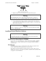
Installing Internal Hardware Options
Warning
You must disconnect the power cable, floppy cable, and any other external cables
connected to the unit before removing the back cover.
DRAM Dual Inline Memory Modules (SODIMMs)
You can order your system CPU factory-configured with either 128 MB or 256 MB of
DRAM. You can reconfigure DRAM capacity by changing the DRAM SODIMM on
your CPU board.
PC/104 Boards
The PC/104 connector supports a 16-bit interface. The connectors are placed on the
board so that PC/104 stack-through interface boards can be used.
Four standoffs are already attached to the CPU board. If you want to stack a second
PC/104 card on the first, you need the four standoffs contained in the Documentation Kit
(see page 12 for more information).
25
143243 (D)
3300 Series Flat Panel Industrial PC
Chapter 2 – Installation
Note
Installation of PC/104 cards may void EMC and Hazardous Locations compliance.
This is a function of the PC/104 card design. It is the system integrator and/or user’s
responsibility to verify compliance before installing any given card.
Note
To prevent vibration failures, always use the locking screw to attach PC/104 cards.
Perform the following steps to install the PC/104 card:
1. Disconnect the power cable, floppy cable, and any other external cables.
2. On a protective surface, lay the unit on its front panel.
3. Unscrew the three mounting screws from the back cover (refer to Figure 1-5 for
positioning information).
4. Slide the back cover toward the I/O panel, and lift off.
5. Attach the PC/104 card to the four pre-installed standoffs. If you want to install a
second PC/104 card, you must attach the standoffs included in the documentation
kit to the first PC/104 card.
6. If you need to connect the cards to a device outside the unit, remove the access
plate on the I/O panel. You can then pass cables through this area (refer to Figure
1-6).
Installing External Hardware Options
This section explains how to install external hardware options.
External Floppy Drive
Note
To avoid corruption, do not attach or detach the external floppy drive with a disk
installed.
There are four screw holes on the back of the unit to mount an external floppy disk drive
(9000-EXF). Refer to Figure 1-5 for more information.
Note
Make sure the floppy drive cable is able to reach from the external floppy connector to
the system before making the cutout.
26
143243 (D)
3300 Series Flat Panel Industrial PC
Chapter 2 – Installation
Using a Touch Screen
Pro-face/Xycom’s touch screen complies with environmental specifications and
maintains a NEMA 4 seal when panel mounted. The touch screen mouse driver emulates
a Microsoft PS/2 mouse.
Installing the Touch Screen Driver
In order to use the touch screen on your 3300 unit, you must install the proper driver.
For computers running Windows® 98, NT, 2000, or XP, you will be installing the
driver touchbase_windows_kpmt_mons.exe. This driver can be found in the
“Drivers\Touchscreen” folder on the Documentation and Support Library CD that
shipped with your monitor. The default setting is serial mode.
1. Create a folder named “Touch” on your desktop or in the root directory of your
C: drive, and unzip the files into the folder.
2. Click on the file “setup.exe” and follow the directions that appear. Pro-face
suggests that you accept all of the defaults.
3. Calibrate the touchscreen, following the directions in the next section.
Caution
®
When using MS-DOS , the mouse driver must be loaded before the touch screen driver
if both a mouse and touch screen are to be supported.
For computers running MS-DOS®, you will be installing the driver,
touchbase_dos.zip. This driver can be found in the “Drivers\Touchscreen” folder on
the Documentation and Support Library CD that shipped with your monitor.
1. Create a directory named “Touch” in the root directory of your C:\ drive and
unzip the files into the folder.
2. Run the file “install.exe” in the TB458 subdirectory and follow the directions
that appear. Pro-face suggests that you accept all of the defaults.
3. Copy all of the batchfile utilities from the Batch Files subdirectory to C:\
4. Add the command allser.bat to your autoexec.bat file.
5. Re-boot your system.
6. Calibrate the touchscreen, following the directions in the next section.
Caution
It is recommended that you keep all default setting when installing the driver.
The touch screen drivers are located on the Document and Support Library CD, which is
shipped with you unit. Drivers can also be downloaded from
http://www.profaceamerica.com
27
143243 (D)
3300 Series Flat Panel Industrial PC
Chapter 2 – Installation
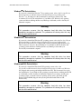
Calibrating the Touch Screen
You need to calibrate the touch screen in the following cases:
•
The cursor does not follow the movement of your finger or pen.
•
You adjust the size of the video image or change the video mode.
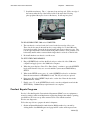
For computers running Windows® 98, NT, 2000, or XP: Before calibrating your touch
screen, Pro-face strongly recommends altering the following default settings in the
calibration program.
1. Go to START/PROGRAMS/UPDD/SETTINGS
2. Click on the Calibration tab.
3. Set the Calibration points to 25.
4. Set the Margin Percentage to 1.
Note
If the Margin Percentage is set to 0, the calibration may not be correct at
the edges of the screen, causing the cursor to jump unexpectedly.
5. Click on the Settings tab.
6. Set the Averaging to 0.
7. Click Apply.
You are now ready to calibrate your touch screen. Follow the instructions found in the
applet listed below to calibrate the touch screen:
START/PROGRAMS/UPDD/CALIBRATE
Note
The touch screen and controller is a matched pair calibrated at the factory. If touch
screen and controllers are interchanged calibration may be needed.
For computers running MS-DOS®, the touch screen drivers must be loaded before you
can calibrate. After the drivers are loaded, switch to C:\Touch, and run TBCAL.EXE to
calibrate the touch screen:
1. Enter the "H" command for hard calibrate
2. Touch the cross hairs as directed by the calibrate utility
3. Save the settings
4. Exit the calibrate utility with the "X" command
28
143243 (D)
3300 Series Flat Panel Industrial PC
Chapter 2 – Installation
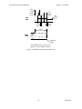
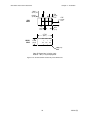
Custom Logo
You may cover the Pro-face/Xycom label on the unit with a customized label. The
dimensions of the existing Pro-face/Xycom label are shown below. Recommended
material for the customized label is 0.007 polyester, with 3M #468 adhesive on the far
side.
Figure 2-9. Logo Label Dimensions
Creating Customized Keypad Inserts
You can customize your 3308/3310/3312 keypads with keypad inserts to match the
function keys that you program. All the keys are relegendable, except the F/A, SPACE, and
+ keys, and the numeric keypad. (See Chapter 3 for more information.) The following
figures provide the necessary dimensions and recommended requirements to create
customized keypad inserts.
29
143243 (D)
3300 Series Flat Panel Industrial PC
Chapter 2 – Installation
3308KP Keypad Inserts
Figure 2-10. 3308KP F1-F12 Insert Dimensions
Figure 2-11. 3308KP F13-F20 Insert Dimensions
30
143243 (D)
3300 Series Flat Panel Industrial PC
Chapter 2 – Installation
1.083
(27.5)
.510
(13.0)
TYP.
0.828
(21.0)
FAR
SIDE
.145
(3.7)
TYP.
.545
(13.8)
TYP.
.074
(1.9)
2.722
(69.1)
PF1
NEAR
SIDE
1.266
(32.2)
U
PF4
X
PF2
V
PF5
Y
PF3
W
PF6
Z
.090 (2.3)
RAD
Note: All dimensions in inches (mm)
Material: .007 (.178) thick polyester
Figure 2-12. 3308KP Control Key Insert Dimensions
31
143243 (D)
3300 Series Flat Panel Industrial PC
Chapter 2 – Installation
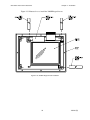
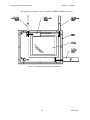
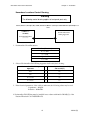
Figure 2-13 illustrates how to install the 3308KP keypad inserts.
Figure 2-13. 3308KP Keypad Insert Installation
32
143243 (D)
3300 Series Flat Panel Industrial PC
Chapter 2 – Installation
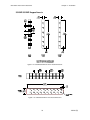
3310KP/3312KP Keypad Inserts
Figure 2-14. 3310KP/3312KP PF1-PF12 Insert Dimensions
Figure 2-15. 3310KP/3312KP F1-F20 Insert Dimensions
33
143243 (D)
3300 Series Flat Panel Industrial PC
Chapter 2 – Installation
1.083
(27.5)
.510
(13.0)
TYP.
0.828
(21.0)
FAR
SIDE
.145
(3.7)
TYP.
.545
(13.8)
TYP.
.074
(1.9)
2.722
(69.1)
PF1
NEAR
SIDE
1.266
(32.2)
U
PF4
X
PF2
V
PF5
Y
PF3
W
PF6
Z
.090 (2.3)
RAD
Note: All dimensions in inches (mm)
Material: .007 (.178) thick polyester
Figure 2-16. 3310KP/3312KP Control Key Insert Dimensions
34
143243 (D)
3300 Series Flat Panel Industrial PC
Chapter 2 – Installation
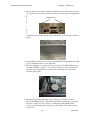
The picture below illustrates how to install the 3310KP/3312KP keypad inserts.
Figure 2-17. 3310KP/3312KP Keypad Insert Installation
35
143243 (D)
3300 Series Flat Panel Industrial PC
Chapter 2 – Installation
Hazardous Location Installations
Pro-face designed the systems to meet Class I, Division 2 Hazardous Location
application requirements. Division 2 locations are locations that are normally nonhazardous, but could potentially become hazardous should accidents expose the area to
flammable vapors, gases, or combustible dusts.
These systems have been designed as non-incendiary devices. They are not intrinsically
safe and should never be operated within a Division 1 (normally hazardous) location
when installed as described here. Nor should any peripheral interface device attached to
these systems be located within Division 1 locations unless approved and/or certified
diode barriers are placed in series with each individual signal and DC power line. Any
such installations are beyond the bounds of Pro-face design intent. Pro-face accepts no
responsibility for installations of this equipment or any devices attached to this
equipment in Division 1 locations.
Note
When adding cards to the system, the user must ensure that they meet operating
conditions for Class I, Division 2 Hazardous Locations.
It is the customer’s responsibility to ensure that the product is properly rated for the
location. If the intended location does not presently have a Class, Division, and Group
rating, then users should consult the appropriate authorities having jurisdiction to
determine the correct rating for that Hazardous Location.
In accordance with federal, state/provincial, and local regulations, all Hazardous
Location installations should be inspected by the authority having jurisdiction, prior to
use. Only technically qualified personnel should install, service, and inspect these
systems.
Warning
Suitable for use in Class I, Division 2, Groups A, B, C, and D, and Class II, Division 2,
Groups F and G Hazardous Locations or Non-hazardous Locations only.
Warning - Explosion Hazard
Substitution of components may impair suitability for Class I, Class II, Division 2.
Advertissement Risque D’Explosion
La substitution de composants peut rendre ce materiel inacceptable pour les
emplamements de classe I, II, Division 2.
36
143243 (D)
3300 Series Flat Panel Industrial PC
Chapter 2 – Installation
Warning - Explosion Hazard
Do not disconnect equipment unless the power has been disconnected or the area is
known to be non-hazardous.
Advertissement Risque D’ Explosion
Avant de deconnecter l’equipment, coupler le courant ou s’assurer que l’emplacement
est designe non dangereux.
Advertissement Risque D’ Explosion
Dans les situations hasardees, couper la courant avant de remplacer ou de cabler les
modules.
Warning - Explosion Hazard
When operating in Hazardous Locations, disconnect power before replacing or wiring
modules.
Warning
To maintain a safe condition, do not attach an external keyboard or mouse to the rear
port when the unit is operating in a hazardous environment.
Definitions
The following Class and Division explanations are derived from Article 500 (Sections 5
and 6) of the United States National Fire Protection Agency National Electric Code
(NFPA 70, 1990). They are not complete and are included here as a general description
for those not familiar with generic Hazardous Location requirements.
People charged with installing this equipment in Hazardous Locations are responsible for
ensuring that all relevant codes and regulations related to location rating, enclosure, and
wiring are met.
Class I Locations
Class I locations are those in which flammable gases or vapors are or may be present in
the air in quantities sufficient to produce explosive or ignitable mixtures.
Class II Locations
Class II locations are those that are, or may become, hazardous because of the presence
of combustible dust.
Division 1 Locations
Division 1 locations are those in which flammable or ignitable gases, vapors, or
combustible dusts and particles can exist due to the following conditions:
37
143243 (D)
3300 Series Flat Panel Industrial PC
Chapter 2 – Installation
Normal operating conditions.
Because of repair, maintenance conditions, leakage, or where mechanical failure or
abnormal operation of machinery or equipment might release or cause explosive or
ignitable mixtures to be released or produced.
Combustible dusts of an electrically conductive nature may be present in hazardous
quantities.
Note
Pro-face systems are not suitable for installation within Division 1 locations.
Note
Electrical equipment cannot be installed in Division 1 locations unless it is intrinsically
safe, installed inside approved explosion-proof enclosures, or installed inside approved
purged and pressurized enclosures.
Division 2 Locations
Division 2 locations are listed below:
Class I volatile flammable liquids or flammable gasses are handled, processed, or
used, but confined within closed containers or closed systems from which they can
escape only in cases of accidental rupture or breakdown of such enclosures or
systems, or in case of abnormal operation of equipment.
Ignitable concentrations of Class I vapors or gasses are normally prevented by
positive mechanical ventilation, but which may become hazardous due to mechanical
failure of those ventilation systems.
Location is adjacent to a Division 1 location.
Class II combustible dust is not normally in the air in quantities sufficient to produce
explosive or ignitable mixtures. Dust accumulations are normally insufficient to
interfere with normal operation of electrical equipment or other apparatus.
Combustible dust may be in suspension in the air as a result of the following:
infrequent malfunctioning of handling or processing equipment; combustible dust
accumulations on, or in the vicinity of electrical equipment; may be ignitable by
abnormal operation or failure of electrical equipment.
38
143243 (D)
3300 Series Flat Panel Industrial PC
Chapter 2 – Installation
Group Ratings
All electrical equipment that is approved for use in Hazardous Locations must include a
group rating. Various flammable and combustible substances are divided into these
groups as a function of their individual maximum experimental safe gap (MESG),
explosion pressure, and ignition temperature.
Component temperatures and the potential for spark based upon voltage, current, and
circuit characteristics, within electrical equipment, will determine what the equipment
group rating will be. A device approved for installation within Class I, Group A locations
may also be used in Groups B, C, or D.
Note
Approved Class I equipment may not be suitable for Class II installations. Class I
includes Groups A, B, C, and D. Class II includes Groups F and G.
Enclosures
The systems are designed to be installed within clean and dry enclosures for both
ordinary and Hazardous Locations. The front panel meets the requirements of UL and
CSA Type 4, 4X, and 12 enclosures. The enclosure used for Class I Hazardous Locations
should have a minimum rating of Type 12 (NEMA 12, IP 5X). However, Type 4 (IP 6X)
enclosures are strongly recommended.
Panel flatness and rigidity are important to maintain a proper panel seal. If you are going
to use non-metal type enclosures, such as plastic or fiberglass, install a rigid metal
stiffener behind the front panel. Failure to do so may result in an inadequate panel seal
due to flexure of the front panel material between the stud mounts. Tighten the nuts on
the mounting studs to 25 inch-pounds.
Requirements for enclosure fittings, conduit, and wiring vary according to the specific
rating of the location and the type of flammable or combustible material involved. Those
requirements are beyond the scope of this document. It is the customer’s responsibility to
ensure that the installation is compliant with codes and regulations that apply to the
specific location. Reference NFPA 70, Article 500 for specific regulations in the United
States.
Power Switch
The systems do not have a power switch. The amount of input power required by these
systems classifies the power switch as an incendiary device because the voltage and
current across the make/break device are capable of creating a spark.
Hazardous Location regulations state that a power switch rated for ordinary locations
may be used if it is located in a non-hazardous area. However, limits in cable length
between the workstation and the power switch may apply. Otherwise, the switch must be
compliant with Class I, Division 1 requirements (intrinsically safe). These switches are
built in a manner that prevents the possibility of a spark when contacts are made or
broken.
Use suitable UL-listed and/or CSA-certified Class I, Division 1 switches in Hazardous
Locations. These switches are available from a number of sources. It is the customer’s
39
143243 (D)
3300 Series Flat Panel Industrial PC
Chapter 2 – Installation
responsibility to ensure that the power switch selected for the installation has the correct
Hazardous Location rating for the location in which it is installed.
Cable Connections
Division 2 Hazardous Location regulations require that all cable connections be provided
with adequate strain relief and positive interlock. Never connect or disconnect a cable
while power is applied at either end of the cable.
Communication Cable Interfaces
All communication cables should include a chassis ground shield. This shield should
include both copper braid and aluminum foil. The D-sub style connector housing should
be a metal conductive type (e.g., molded zinc), and the ground shield braid should be
well terminated directly to the connector housing. Do not use a shield drain wire.
The outer diameter of the cable must be suited to the inner diameter of the cable
connector strain relief to ensure that a reliable degree of strain relief is maintained.
Always secure the D-Sub connectors to the workstation mating connectors via the two
screws located on both sides.
Warning
Never connect or disconnect the communication cables while power is applied at either
end of the cable. This may result in an incendiary spark. Permanent damage to the
workstation communication components may occur.
Note
This warning does not apply to the front panel keyboard interface connector. This
connection is a nonincendive circuit. Please reference the Hazardous Locations control
drawing on page 41.
40
143243 (D)
3300 Series Flat Panel Industrial PC
Chapter 2 – Installation
Hazardous Locations Control Drawing
Warning
The following control drawing applies to front panel ports only.
Class I, Division 2, Groups A, B, C and D, and Class II, Division 2, Groups F and G Hazardous (Classified) Locations.
Pro-face/Xycom Model
3310KP(T) or
3312KP(T)
Nonincendive Field
Wiring Apparatus
Front Panel PS2 Port
(see note 1)
Notes:
1. Nonincendive Circuit Parameters:
PS/2 Port (Pins 3 to 4)
Voc = 5 VDC
Isc = 3.3 A
Ca = 10 uF
La = 4 uH
2. Selected Nonincendive Field Wiring Apparatus shall satisfy the following:
Nonincendive Field Wiring
Apparatus
Pro-face/Xycom Model 3310 KP(T)
and 3312KP(T)
Vmax
≥
Voc
Imax
≥
Isc
Ci + Ccable
≤
Ca
Li + Lcable
≤
La
3. If the electrical parameters of the cable are unknown, the following values may be used:
Capacitance – 60 pF/ft
Inductive – 0.20 uH/ft
4. Nonincendive Field Wiring must be installed in accordance with Article 501.4(B)(3) of the
National Electrical Code ANSI/NFPA 70.
41
143243 (D)
3300 Series Flat Panel Industrial PC
Chapter 2 – Installation
Operation and Maintenance
The systems have been designed to comply with relevant spark ignition tests. However,
the workstation front panel membrane switches are the only make/break components
intended to be used by the operator in normal operation.
Warning
To maintain a safe condition, do not attach an external keyboard or mouse to the rear
port when the unit is operating in a hazardous environment.
Always observe the following rules with respect to Hazardous Location installations:
1. Always install the workstations within an enclosure suitable for the specific
application. General-purpose enclosures may be acceptable for Class I applications,
but are never acceptable for Class II applications. Type 4 (IP 65) enclosures are
recommended even when not required by regulations.
2. Keep enclosure doors or openings closed at all times to avoid the accumulation of
foreign matter inside the workstation.
3. Never subject the unit to any installation or service procedures unless power is
removed and the area is non-hazardous. This includes installing or removing power
cables or communication cables, or removing the unit’s back cover.
4. Only technically qualified service personnel should perform installation and service.
These workstations are designed to require no service in the course of normal
operation by an operator.
Safety Agency Approval
The 3308, 3310 and 3312 systems have been designed to meet the following standards:
Underwriters Laboratories Inc., UL 1604 Standard for Safety
Electrical equipment for use in Class I and Class II, Division 2, and Class III
Hazardous (classified) Locations
Underwriters Laboratories Inc., UL 508
Industrial Control Equipment
Canadian Standard Association, Specification C22.2 No. 213-M1987
Non-incendiary electrical equipment for use in Class I, Division 2 Hazardous
Locations
Canadian Standards Association, Specification C22.2 No. 142
Process Control Equipment
EN60950, Information Technology Equipment
42
143243 (D)
Chapter 3 – Keypad Functionality
The 3308KP, 3310KP(T) and 3312KP(T) include function/alpha, control/alpha, numeric,
and cursor control keypads.
Control Keypad
3308KP
The keypad on the 3308KP unit provides seven control keys, six alpha keys (U-Z) and
the space and + keys. The CTRL, SHIFT, INS, ALT, TAB, DEL, SPACE, and + keys provide the
same functions as can be found on a standard PC/AT-compatible keyboard.
Six of the keys are relegendable, as shown in Figure 3-1. Refer to the Creating
Customized Keypad Inserts section in Chapter 3 for detailed information.
Figure 3-1. 3308KP Control/Alpha Keypad
3310KP(T)/3312KP(T)
The keypads on the 3310KP(T) and 3312KP(T) provide seven control keys, as well as
the space and + keys. The CTRL, SHIFT, INS, ALT, TAB, DEL, SPACE, and + keys provide the
same functions as can be found on a standard PC/AT-compatible keyboard.
Six of the keys are relegendable, as shown in Figure 3-2. Refer to the Creating
Customized Keypad Inserts section in Chapter 3 for detailed information.
43
143243(D)
3300 Series Flat Panel Industrial PC
Chapter 3 – Keypad Functionality
Figure 3-2. 3310KP(T)/3312KP(T) Control Keypad
Alternate Configuration
The 3310KP(T) and 3312KP(T) workstations come with an alternate insert that you may
use for these six relegendable keys. This alternate insert replaces the PC control key
labels with function key labels. Your unit is shipped with batch files that you can use
with the keypad utility to reprogram the keys (see the Loading the Keypad Utility section
in the next chapter).
Function and Alpha Modes
When you press and hold the F/A key, the keypad switches to alpha mode. This allows
you to access the alpha characters A-Z, as well as the punctuation symbols on the 3308
KP, 3310KP(T) and 3312KP(T) units. The punctuation notations are blue letters located
in the bottom right-hand corner of the keys.
Note
On 3308KP units, the default setting for alpha characters is lowercase. If you want to
use uppercase alpha characters, you must reprogram the keypads using the keypad
utility (see the Loading the Keypad Utility section in the next chapter).
When the F/A key it is not pressed, the keypads default to function mode. The default
setting notations are white letters located in the top left-hand corner of the keys.
Note
On 3308KP units, you cannot access the CTRL, SHIFT, INS, ALT, TAB, and DEL keys in
alpha mode. In other words, these keys cannot be used in combination with alpha keys.
44
143243 (D)
3300 Series Flat Panel Industrial PC
Chapter 3 – Keypad Functionality
Numeric Keypad
The numeric keypad features numbers 0-9, plus the decimal and minus sign characters.
Figure 3-3. Numeric Keypad
Cursor Control Keypad
The cursor control keypad features 10 cursor control keys: BACKSPACE, PREV, NEXT, ESC,
ENTER, HOME (the center key), and the up, down, right, and left arrow keys.
Figure 3-4.3300 Series Cursor Control Keypad
You can use the cursor control keys in conjunction with the F/A key to control the
brightness on 3308KP passive-color flat panel display units.
45
143243 (D)
3300 Series Flat Panel Industrial PC
Chapter 3 – Keypad Functionality
Function/Alpha Keypads
3308KP
The twenty function/alpha keys (F1-F20, A-T,) on the 3308KP are relegendable. Refer to
the Creating Customized Keypad Inserts section in Chapter 2 for detailed information.
Figure 3-5. 3308KP Function/Alpha Keypads
46
143243 (D)
3300 Series Flat Panel Industrial PC
Chapter 3 – Keypad Functionality
3310KP
The thirty-two PF/function/alpha keys (PF1-PF12, F1-F20, and A-Z and punctuation
symbols) on the 3310KP are relegendable. Refer to the Creating Customized Keypad
Inserts section in Chapter 2 for detailed information.
The PF1-PF6 keys are equal to CTRL+F1 through CTRL+F6. PF7-PF12 are equal to ALT+F1
through ALT+F6.
Figure 3-6. 3310KP(T) and 3312KP(T) PF/Function/Alpha Keypads
47
143243 (D)
Chapter 4 – Keypad Utility
The keypad utility program allows you to redefine any or all of the keypad keys on the
unit with new scan codes, using utility software. You must use an external full-stroke
PC/AT keyboard to access the utility. This chapter explains how to load the keypad
utility, and details how the program’s pull-down menus work. Also included in this
chapter are the default keypad scan codes.
Note
Your external full-stroke PC/AT keyboard cannot be redefined by running the
keypad utility.
Note
The keypad switch arrays are disabled while the keypad utility is running.
Loading the Keypad Utility
Note
Pro-face’s keypad utility will only run under DOS 3.2 or better. The keypad
utility will not run in a Windows environment.
The keypad utility is on the “Documentation & Support Library” CD that shipped with
your computer. You will find the self-extracting zip file, Keypad Utility 1.2 142606001.exe, in the folder:
DRIVERS\Keypad Software\Keypad Utility 1.1 142606-001
If your computer is running DOS (revision 3.2 or better), create a subdirectory on your
hard drive for the files, and extract the files on the disk into that subdirectory. To run the
utility, go to the subdirectory and type kp3util at the DOS prompt.
If your computer is not running DOS, you will need to extract the files onto a
DOS-bootable diskette. The diskette is then inserted into the floppy drive. You will need
to reboot your computer for the computer to access the program. To run the utility, type
kp3util at the DOS prompt.
Using the Keypad Utility
The keypad utility uses a menu bar and pull-down menu system. All menu bars are
displayed across the top of the screen. “Pro-face/Xycom KP3 Utility” and the current
menu titles are shown at the bottom of the screen (see Figure 4-1).
48
143243(D)
3300 Series Flat Panel Industrial PC
Chapter 4 – Keypad Utility
A full-stroke keyboard is needed to enter keystrokes while recording a new key macro,
editing an existing macro, or entering utility commands. You can redefine all keys on the
keypads, except the F/A (Function/Alpha) key. While the utility is running, the keypads
are disabled.
Dialog boxes appear for user prompts, and to display error and user advice messages.
Any keys used specifically in each menu are shown at the bottom of each screen (see
Figure 4-1).
Two keys allow you to exit the menus:
•
ESC moves
•
F1 returns to the current menu headings in some of the menus where Exit can be
chosen to exit this menu
to the previous menu or out of the utility from the Main Menu
Startup
To begin using the keypad utility, type kp3util at the prompt (for the floppy drive when
no DOS is available, or the subdirectory you created earlier). The program will bring up
the main menu. Open the default keypad settings files in the main menu to program the
keypad. For the 3308 units, the default file is def3308.pkm. For the 3310 and 3312 units,
the default file is def3310.pkm file. Changes to the default file should be saved to a new
file with the pkm extension. If you do not open a file, the macros pull-down menu will
not be available.
Note
If you make any changes to your keypad and want to set it back to the default settings,
open the pkm file for your unit (e.g., def3310.PKM for 3312KP(T)) from the
File/Open menu, and then download it from the download menu.
Caution
Do not save any changes to the default files.
49
143243 (D)
3300 Series Flat Panel Industrial PC
Chapter 4 – Keypad Utility
Main Menu
Figure 4-1 shows the Main Menu screen. The functions of the pull-down menus are
described in the following sections.
Note
Exit and Download do not have pull-down menus.
Note
Use F1 to access the menu bar options in the kp3util program.
Exit
Files
Macros
Upload
Open
Function Keys
KP Ctl. Version
Download
Utilities
Factory Default
Close
Alpha Keys
Exit
Exit
Save
Save As
Delete
Exit
<Company Name> KP3 Utility: MAIN
L-Arrow, R-Arrow, Enter
Figure 4-1. Main Menu, showing first-level pull-down menus
Exit
Exit closes any open files and exits the utility. ESC can also be used for this purpose.
ESC works for exiting the other menus as well.
Files Menu
When you choose Files, a pull-down menu will display these choices: Open, Close, Save,
Save As, Delete, and Exit. The following table describes these menu commands.
Table 4-1. Files Menu
Command
Description
Open
Opens a file that contains a macro set for the keypad and loads the
contents into memory. Any macro set in memory is overwritten. Once
loaded, the macro set is available to edit, view, teach, or download to
the keyboard controller.
Close
Clears the macro set from memory and closes the file from which the
set came.
Save
Copies the macro set from memory back into its original file. The
original file contents are overwritten.
50
143243 (D)
3300 Series Flat Panel Industrial PC
Chapter 4 – Keypad Utility
Table 4-1. Files Menu
Command
Description
original file contents are overwritten.
Save As
Creates a new file under the specified name and copies the macro set
from memory into it. For example, to define different sets of codes,
save each set under a different name and download the one you wish
to use.
Delete
Deletes a file.
Exit
Returns to the Main Menu.
You can save files containing keypad macro sets (a macro for each key) on disk, and then
load them into memory to view, edit, teach, or download to the keyboard controller.
Some of these files may be included in the utility package for use in reconfiguring the
keypads for different software packages, and as templates for defining completely new
keypad macro sets.
Macros Menu
Note
You must have a macro file in memory before the Macros Menu is available.
To load a macro file, select the File/Open menu.
When you select Macros, a keypad-type pull-down menu is available. This pull-down
menu provides the following choices: Function Keys, Alpha Keys, and Exit. Table 4-2
explains the commands in the Macros Keypad Type menu.
Table 4-2. Macros Keypad Type Menu
Command
Description
Function Keys
Selects the function keys on the keypad to view, edit, or teach.
Alpha Keys
Selects the alpha keys on the keypad to view, edit, or teach.
Exit
Returns to the main menu.
After choosing which keys you want to work with (Function or Alpha), another pulldown menu becomes available. This macros edit menu displays the following choices:
Exit, View, Teach, and Edit. Table 4-3 explains the commands in the Macros Edit menu.
51
143243 (D)
3300 Series Flat Panel Industrial PC
Chapter 4 – Keypad Utility
Table 4-3. Macros Edit Menu
Command
Description
Exit
Returns to the Main Menu.
View
Lets you view, but not edit, the macro for the selected key. When View is chosen,
the Exit option is displayed on the menu bar and a graphic representation of the
chosen keypad is shown. To return to the Macros Menu, select Exit from the
View Menu.
To select a key to view, use the arrow keys to position the cursor on the desired
key and press ENTER. The macro is displayed as two lines: ASCII and code. The
ASCII line displays each keycode as the keys it represents on the full-stroke
keyboard. Special labels are used for certain keys (e.g., Spc for space bar, UAr
for up arrow, and bk for the break code prefix). The code line is displayed in
either Hex or decimal. There is a one-to-one correspondence between the ASCII
and code lines.
While viewing the macro, the menu bar displays two options: Exit and
Hex/Decimal. To access the menu bar, use F1. Exit returns to the View Menu;
Hex/Decimal toggles between displaying the macro in hex or decimal format.
When Hex is chosen, the keycodes are displayed as hexadecimal value scan
codes. When Decimal is chosen, the keycodes are displayed as the decimal
equivalent of the hex codes.
For example, the macro abc would be displayed as 1C F0 1C 32 F0 32 21 F0 21
in hex, and 28 240 28 50 240 50 33 240 33 in decimal.
Teach
Allows you to record up to 105 keystrokes in a macro. When Teach is selected, a
graphic representation of the keypad currently in memory displays. Menu bar
choices are Exit, ASCII, and Click OFF. To access the menu bar, use F1.
As usual, Exit returns you to the Macros menu. ASCII specifies the format to
display the keystrokes as they are entered. ASCII is the default setting. The Click
OFF choice is not supported.
To select a key to define, use the arrow keys to position the cursor on the desired
key and press ENTER. After you select a key, the utility records every keystroke
made on the external full-stroke keyboard. The keystrokes are saved in a macro
assigned to the chosen key. As the keystrokes are entered, they are displayed
using the chosen format.
ESC stops recording and returns you to the Teach Menu, so you cannot record
the ESC key. However, ESC can be included in a macro by using the editor.
Changes made to the macros in the Teach Menu are not programmed until you
select Download.
52
143243 (D)
3300 Series Flat Panel Industrial PC
Chapter 4 – Keypad Utility
Table 4-3. Macros Edit Menu
Command
Description
Edit
Displays a graphic representation of the keypad in memory and a menu bar
displaying Exit and Click OFF. Exit returns to the Macros menu. Click OFF is not
supported.
To select a key to edit, use the arrow keys to position the cursor on the desired
key and press ENTER. In edit mode, the macro is displayed as two lines. The top
line displays the macro in either hex or decimal format, and is the line in which
the editing takes place. The bottom line displays the macro in ASCII format; this
line is not user configurable. The bottom line keeps track of which part of the
macro being edited, and is updated by the utility as editing takes place. The
insert, delete, and cursor control keys on the full-stroke keyboard are active for
editing.
When a key is selected from the Edit Macro option, the menu bar displays the
following choices: Exit, Cut, Copy, Paste, Codes, Hex, and I/O (Insert/Overtype).
The macro for the chosen key is also displayed. To access the menu bar, use F1.
Edit/Cut
Cut deletes a sequence of scan codes from the macro. To select a section to cut:
1. Place the cursor on the first character to cut.
2. Press F1 (to access the menu bar choices) and select CUT.
3. Press ENTER. Cut should still be highlighted, but the cursor will appear on the
Edit line. Move the cursor on the last character to cut and press ENTER.
The last character of every macro is the end of the macro (EOM) and cannot be
deleted.
Edit/Copy
Copy duplicates a sequence of scan codes from the macro into memory. To
select the section to copy:
1. Place the cursor on the first character to copy. Press F1 and select Copy.
2. Press ENTER. Copy should still be highlighted, but the cursor will appear on
the Edit line.
3. Move the cursor to the last character to copy and press ENTER.
The copied item does not appear on the screen until you select Paste.
Edit/Paste
Paste inserts a sequence of scan codes (which were saved in memory using
Copy) into the macro. To paste a sequence of scan codes that were previously
copied, position the cursor where you want the text to appear and then press F1.
Select Paste and then press ENTER.
Codes displays a table of keys and their scan codes in Hex. See the Codes
section in this chapter for a complete code listing.
Hex/Decimal toggles between displaying the scan codes in Hex and Decimal
formats.
I/O allows you to either insert text or type over text in the code(s). Use the Insert
key on your full-stroke external keyboard to toggle between insert and overtype
mode.
53
143243 (D)
3300 Series Flat Panel Industrial PC
Chapter 4 – Keypad Utility
Note
The 3300KP(T) units do not support the programming of special functions such
as caps lock, Number lock, or scroll lock.
Upload Menu
Use the Upload Menu to access the keypad version. As illustrated in Table 4-4, the
choices in this menu are Keypad Version and Exit.
Table 4-4. Upload Menu
Command
Description
Keypad
Version
Commands the keyboard controller to send its firmware
revision number.
Exit
Returns to the Main Menu.
Download Menu
Note
Download contains no options. If you select Download, any macro set previously programmed is overwritten.
Caution
The macros set in memory should be saved before downloading. If they are
not saved, all changes will be lost.
Download should be used only after all the keypad keys have been programmed and
saved to a *.pkm file. Selecting Download prior to saving changes will result in a loss of
all keypad macro programming.
When you select Download, the program creates a download file called download.dld
and loads the keypad controller’s non-volatile memory with the new macros, which
become the new key definitions for the keypad. After the download is complete, the
system will prompt you to cycle power.
Utilities Menu
When the Utilities menu is selected, two choices are displayed: Factory Default, and
Exit. Table 4-5 explains these choices.
54
143243 (D)
3300 Series Flat Panel Industrial PC
Chapter 4 – Keypad Utility
Table 4-5. Utilities Menu
Command
Description
Factory Default
Reprograms the keypad macros to the factory default settings. After
completion, the system will need to be power cycled.
Exit
Returns to the Main Menu.
Utility Batch Mode
The Utility Batch Mode can be used to reprogram keypads on multiple units with the
same customized keypad macros. This feature is useful because it allows you to do the
reprogramming without having to enter the full keypad utility for each individual unit.
After you have programmed the first keypad macros, you will need to create a DOSbootable diskette to run the Utility Batch Mode.
You will need to extract files from the Documentation and Support Library CD-ROM to
for the diskette. The necessary files can be found in the folder,
DRIVERS\Keypad Software\Keypad Utility 1.1 142606-001
Save the following files from the CD-ROM to the root directory on your DOS-bootable
diskette:
H8flash.exe
KP3util.exe
H8fload.mot
*.pkm
codes.pkm
symbols.pkm
download.dld
Then, insert the diskette into the unit you want to reprogram and reboot it. At the DOS
prompt, type the kp3util *.pkm to run the reprogramming function. This utility can be
used on as many units as necessary.
Note
The *.pkm file is the macro file you saved in the earlier step. The * indicates
the name you selected for the file.
Note
The download.dld file was created after the last keypad programming process.
The programming process could be either new keypad programming, or the
reprogramming of the keypad to the factory default settings.
55
143243 (D)
3300 Series Flat Panel Industrial PC
Chapter 4 – Keypad Utility
Keypad Scan Codes
Table 4-6 through Table 4-13 list the default keypad scan codes produced by the keypad
utility.
Table 4-6. Keypad Codes for Lowercase Letters
Key
Edit Mode in Macros Edit Menu
Make Code
Break Code
a
1C
1C
F0 1C
b
32
32
F0 32
c
21
21
F0 21
d
23
23
F0 23
e
24
24
F0 24
f
2B
2B
F0 2B
g
34
34
F0 34
h
33
33
F0 33
i
43
43
F0 43
j
3B
3B
F0 3B
k
42
42
F0 42
l
4B
4B
F0 4B
m
3A
3A
F0 3A
n
31
31
F0 31
o
44
44
F0 44
p
4D
4D
F0 4D
q
15
15
F0 15
r
2D
2D
F0 2D
s
1B
1B
F0 1B
t
2C
2C
F0 2C
u
3C
3C
F0 3C
v
2A
2A
F0 2A
w
1D
1D
F0 1D
x
22
22
F0 22
y
35
35
F0 35
z
1A
1A
F0 1A
56
143243 (D)
3300 Series Flat Panel Industrial PC
Chapter 4 – Keypad Utility
Table 4-7. Keypad Codes for Left-Shifted (Uppercase) Letters
Key
Edit Mode in Macros Edit Menu
Make Code
Break Code
A
12 1C
12 1C
F0 1C F0 12
B
12 32
12 32
F0 32 F0 12
C
12 21
12 21
F0 21 F0 12
D
12 23
12 23
F0 23 F0 12
E
12 24
12 24
F0 24 F0 12
F
12 2B
12 2B
F0 2B F0 12
G
12 34
12 34
F0 34 F0 12
H
12 33
12 33
F0 33 F0 12
I
12 43
12 43
F0 43 F0 12
J
12 3B
12 3B
F0 3B F0 12
K
12 42
12 42
F0 42 F0 12
L
12 4B
12 4B
F0 4B F0 12
M
12 3A
12 3A
F0 3A F0 12
N
12 31
12 31
F0 31 F0 12
O
12 44
12 44
F0 44 F0 12
P
12 4D
12 4D
F0 4D F0 12
Q
12 15
12 15
F0 15 F0 12
R
12 2D
12 2D
F0 2D F0 12
S
12 1B
12 1B
F0 1B F0 12
T
12 2C
12 2C
F0 2C F0 12
U
12 3C
12 3C
F0 3C F0 12
V
12 2A
12 2A
F0 2A F0 12
W
12 1D
12 1D
F0 1D F0 12
X
12 22
12 22
F0 22 F0 12
Y
12 35
12 35
F0 35 F0 12
Z
12 1A
12 1A
F0 1A F0 12
57
143243 (D)
3300 Series Flat Panel Industrial PC
Chapter 4 – Keypad Utility
Table 4-8. Keypad Codes for Numeric and Punctuation Keys
Key
Edit Mode in Macros Edit Menu
Make Code
Break Code
`
0E
0E
F0 0E
1
16
16
F0 16
2
1E
1E
F0 1E
3
26
26
F0 26
4
25
25
F0 25
5
2E
2E
F0 2E
6
36
36
F0 36
7
3D
3D
F0 3D
8
3E
3E
F0 3E
9
46
46
F0 46
0
45
45
F0 45
-
4E
4E
F0 4E
=
55
55
F0 55
[
54
54
F0 54
]
5B
5B
F0 5B
\
5D
5D
F0 5D
;
4C
4C
F0 4C
‘
52
52
F0 52
,
41
41
F0 41
.
49
49
F0 49
/
4A
4A
F0 4A
58
143243 (D)
3300 Series Flat Panel Industrial PC
Chapter 4 – Keypad Utility
Table 4-9. Keypad Codes for Left-Shifted Punctuation Keys
Key
Edit Mode in Macros Edit Menu
Make Code
Break Code
~
0E
0E
F0 0E
!
16
16
F0 16
@
1E
1E
F0 1E
#
26
26
F0 26
$
25
25
F0 25
%
2E
2E
F0 2E
^
36
36
F0 36
&
3D
3D
F0 3D
*
3E
3E
F0 3E
(
46
46
F0 46
)
45
45
F0 45
_
4E
4E
F0 4E
+
55
55
F0 55
{
54
54
F0 54
}
5B
5B
F0 5B
|
5D
5D
F0 5D
:
4C
4C
F0 4C
“
52
52
F0 52
<
41
41
F0 41
>
49
49
F0 49
?
4A
4A
F0 4A
59
143243 (D)
3300 Series Flat Panel Industrial PC
Chapter 4 – Keypad Utility
Table 4-10. Keypad Codes for Control & Miscellaneous Keys
Key
Edit Mode in Macros Edit Menu
Make Code
Break Code
Tab
0D
0D
F0 0D
Left Shift Tab
12 0D
12 0D
F0 0D F0 12
Caps Lock
58
58
F0 58
Left Shift
12
12
F0 12
Right Shift
59
59
F0 59
Left Ctrl
14
14
F0 14
Right Ctrl
E0 14
E0 14
E0 F0 14
Left Alt
11
11
F0 11
Right Alt
E0 11
E0 11
E0 F0 11
Space Bar
29
29
F0 29
Backspace
66
66
F0 66
Left Enter
5A
5A
F0 5A
Esc
76
76
F0 76
Insert
E2
E0 12 E0 70
E0 F0 70 E0 F0 12
Home
E3
E0 12 E0 6C
E0 F0 6C E0 F0 12
E3
E0 12 E0 6C
E0 F0 6C E0 F0 12
Page Up
E4
E0 12 E0 7D
E0 F0 7D E0 F0 12
PREV
E4
E0 12 E0 7D
E0 F0 7D E0 F0 12
Delete
E5
E0 12 E0 71
E0 F0 71 E0 F0 12
End
E6
E0 12 E0 69
E0 F0 69 E0 F0 12
Page Down
E7
E0 12 E0 7A
E0 F0 7A E0 F0 12
NEXT
E7
E0 12 E0 7A
E0 F0 7A E0 F0 12
Up Cursor
E8
E0 12 E0 75
E0 F0 75 E0 F0 12
Left Cursor
E9
E0 12 E0 6B
E0 F0 6B E0 F0 12
Right Cursor
EA
E0 12 E0 74
E0 F0 74 E0 F0 12
Down Cursor
EB
E0 12 E0 72
E0 F0 72 E0 F0 12
/
EC
E0 12 E0 4A
E0 F0 4A E0 F0 12
Print Screen
ED
E0 12 E0 7C
E0 F0 7C E0 F0 12
Pause/Break
EE
E0 12 E0 7E
E0 F0 7E E0 F0 12
SysRq PS2
ED
E0 12 E0 7C
E0 F0 7C E0 F0 12
SysRq 88 #1
84
84
F0 84
SysRq 88 #2
7F
7F
F0 7F
][
60
143243 (D)
3300 Series Flat Panel Industrial PC
Chapter 4 – Keypad Utility
Table 4-10. Keypad Codes for Control & Miscellaneous Keys
Key
Edit Mode in Macros Edit Menu
Make Code
Break Code
Scroll Lock
7E
7E
F0 7E
Num Lock
77
77
F0 77
Right *
7C
7C
F0 7C
Right -
7B
7B
F0 7B
Right +
79
79
F0 79
Right Enter
E0 5A
E0 5A
E0 F0 5A
Table 4-11. Keypad Codes for Numeric/Control Keys (with Numlock on)
Key
Edit Mode in Macros Edit Menu
Make Code
Break Code
.
71
71
F0 71
0
70
70
F0 70
1
69
69
F0 69
2
72
72
F0 72
3
7A
7A
F0 7A
4
6B
6B
F0 6B
5
73
73
F0 73
6
74
74
F0 74
7
6C
6C
F0 6C
8
75
75
F0 75
9
7D
7D
F0 7D
Del
12 71
12 71
F0 71 F0 12
Ins
12 70
12 70
F0 70 F0 12
End
12 69
12 69
F0 69 F0 12
Down Cursor
12 72
12 72
F0 72 F0 12
PgDn
12 7A
12 7A
F0 7A F0 12
Left Cursor
12 6B
12 6B
F0 6B F0 12
Blank
12 73
12 73
F0 73 F0 12
Right Cursor
12 74
12 74
F0 74 F0 12
Home
12 6C
12 6C
F0 6C F0 12
Up Cursor
12 75
12 75
F0 75 F0 12
PgUp
12 7D
12 7D
F0 7D F0 12
61
143243 (D)
3300 Series Flat Panel Industrial PC
Chapter 4 – Keypad Utility
Table 4-12. Keypad Codes for Function Keys F1-F20
Key
Edit Mode in Macros Edit Menu
Make Code
Break Code
F1
FF 01
05
F0 05
F2
FF 02
06
F0 06
F3
FF 03
04
F0 04
F4
FF 04
0C
F0 0C
F5
FF 05
03
F0 03
F6
FF 06
0B
F0 0B
F7
FF 07
83
F0 83
F8
FF 08
0A
F0 0A
F9
FF 09
01
F0 01
F10
FF 0A
09
F0 09
F11
78
78
F0 78
F11 (Shift F1)
FF 0B
12 05
F0 05 F0 12
F12
07
07
F0 07
F12 (Shift F2)
FF 0C
12 06
F0 06 F0 12
F13
FF 0D
12 04
F0 04 F0 12
F14
FF 0E
12 0C
F0 0C F0 12
F15
FF 0F
12 03
F0 03 F0 12
F16
FF 10
12 0B
F0 0B F0 12
F17
FF 11
12 83
F0 83 F0 12
F18
FF 12
12 0A
F0 0A F0 12
F19
FF 13
12 01
F0 01 F0 12
F20
FF 14
12 09
F0 09 F0 12
62
143243 (D)
3300 Series Flat Panel Industrial PC
Chapter 4 – Keypad Utility
Table 4-13. Keypad Codes for Function Keys F21-F40 or PF1-PF20
Symbol
Edit Seq.
AT Make
AT Break
XT Make
XT Break
F21 or PF1
FF 15
14 05
F0 05 F0 14
1D 3B
BB 9D
F22 or PF2
FF 16
14 06
F0 06 F0 14
1D 3C
BC 9D
F23 or PF3
FF 17
14 04
F0 04 F0 14
1D 3D
BD 9D
F24 or PF4
FF 18
14 0C
F0 0C F0 14
1D 3E
BE 9D
F25 or PF5
FF 19
14 03
F0 03 F0 14
1D 3F
BF 9D
F26 or PF6
FF 1A
14 0B
F0 0B F0 14
1D 40
C0 9D
F27 or PF7
FF 1B
14 83
F0 83 F0 14
1D 41
C1 9D
F28 or PF8
FF 1C
14 0A
F0 0A F0 14
1D 42
C2 9D
F29 or PF9
FF 1D
14 01
F0 01 F0 14
1D 43
C3 9D
F30 or PF10
FF 1E
14 09
F0 09 F0 14
1D 44
C4 9D
F31 or PF11
FF 1F
11 05
F0 05 F0 11
38 3B
BB B8
F32 or PF12
FF 20
11 06
F0 06 F0 11
38 3C
BC B8
F33 or PF13
FF 21
11 04
F0 04 F0 11
38 3D
BD B8
F34 or PF14
FF 22
11 0C
F0 0C F0 11
38 3E
BE B8
F35 or PF15
FF 23
11 03
F0 03 F0 11
38 3F
BF B8
F36 or PF16
FF 24
11 0B
F0 0B F0 11
38 40
C0 B8
F37 or PF17
FF 25
11 83
F0 83 F0 11
38 41
C1 B8
F38 or PF18
FF 26
11 0A
F0 0A F0 11
38 42
C2 B8
F39 or PF19
FF 27
11 01
F0 01 F0 11
38 43
C3 B8
F40 or PF20
FF 28
11 09
F0 09 F0 11
38 44
C4 B8
Note
If you make any changes to your keypad and want to set it back to the default settings,
open the file titled DEF3308PC.PKM or DEF3308HMI.PKM from the File/Open
menu and then download it from the download menu.
Warning
Do not save any changes to the default files.
63
143243 (D)
Chapter 5 – Motherboard and BIOS Setup
Motherboard and BIOS Setup Overview
To change the CMOS settings for the 3300 BIOS, you must hit <F1> early in the 3300’s
Power-On Self-Test period. The 3300 will display a message at the top of the screen
during this period. Facsimiles of the various submenus (as each displays on the screen)
are shown in the following sections. The menu navigation keystrokes are listed below.
The keystrokes allow you to set and/or modify the values of the menu options.
•
<F1> or <ALT-H> displays General Help Screen. The specific Help messages
will be outlined in each specific menu section
•
<UP> and <DOWN> Arrow keys move between the menu options
•
<Home> or <End> moves to top or bottom of current menu
•
To choose an item, enter the letter next to the option description
•
<Enter> cycles through all options for each item that has options
•
<L>, in the Main Menu, loads factory installed Setup Default Values
•
<Q>, in the Main Menu, quits (i.e., exits Setup without saving changes)
•
<S>, in the Main Menu, saves current settings without exiting Setup
•
<X>, in the Main Menu, saves current settings and exits Setup
64
143243(D)
3300 Series Flat Panel Industrial PC
Chapter 5 – Motherboard and BIOS Setup
Main Setup Menu
The first two options, changing the time and/or date, are performed from this main setup
menu. The next four selections lead to submenus where the settings are verified and/or
modified. The last four selections are the options for accepting or discarding any changes
performed during this session.
XpressRom Setup
Platform: <Company Name> 3300
Built: mm/dd/yyyy hh:mm:ss
Main Menu
A: Time 16:19:20
B: Date 03/02/01
C: Motherboard Device Configuration
D: Memory Optimization
F: Power Management
H: Miscellaneous Configuration
L. Load Defaults
S. Save Values Without Exit
Q. Exit Without Save
X. Save Values and Exit
(Individual help for each item above will be displayed here)
Figure 5-1. Main Menu Setup Screen
System Time
Valid values for the RTC (Real Time Clock) range from 0:0:00 through 23:59:59. Note
that entering the seconds is optional. To change the time, press “A” to choose that
option, and enter the current time in the format hh:mm:ss. To accept the value you have
entered, press <Enter>, or press <Esc> to exit the selection without changing the setting.
System Date
Valid values for the date range from 1/1/1980 through 12/31/2099. To change the date,
press “B” to choose that option, and enter the current date in the format of mm/dd/yyyy.
To accept the value you have entered, press <Enter> or press <Esc> to exit the selection
without changing the setting.
65
143243 (D)
3300 Series Flat Panel Industrial PC
Chapter 5 – Motherboard and BIOS Setup
Motherboard Device Configuration Submenu
The Motherboard Device Configuration Submenu screen is an intermediate screen. It
provides links to the specific configuration screens for the various functional areas. No
settings are viewed, entered, or modified in this screen.
XpressRom Setup
Platform: <Company Name> 3300
Built: mm/dd/yyyy
hh:mm:ss
Motherboard Device Configuration
A. Drive Configuration
B. Super I/O Configuration
F. Video and Flat Panel Configuration
G. PCI Configuration
R. Return to Main Menu
(Individual help for each item above will be displayed here)
Figure 5-2. Motherboard Device Configuration Submenu Screen
66
143243 (D)
3300 Series Flat Panel Industrial PC
Chapter 5 – Motherboard and BIOS Setup
Drive Configuration Submenu
XpressRom Setup
Platform: <Company Name> 3300
Built: mm/dd/yyyy hh:mm:ss
Drive Configuration
IDE Configuration
IDE BIOS Support:
Chipset IDE Channel:
Enabled
Both
DMA/UDMA Support in BIOS:
Disabled
Max PIO/MDAM/UDMA mode for Drive 1: Auto
Max PIO/MDAM/UDMA mode for Drive 2: Auto
Max PIO/MDAM/UDMA mode for Drive 3: Auto
Max PIO/MDAM/UDMA mode for Drive 4: Auto
CD-ROM Boot Configuration
CD-ROM Boot: Enabled
Boot Order Configuration
1. FLOPPY Disk
2. CD-ROM Drive
3. Hard Drive #1
(Individual help for each item above will be displayed here)
Figure 5-3. Drive Configuration Submenu
Note
The 3300 series does not include a CD-ROM drive. The unit will boot
up properly, even if the CD-ROM drive is listed in the Boot Order
configuration.
The Drive Configuration submenu offers two choices: IDE Configuration and Boot
Order Configuration. If you wish to reconfigure either of these items, the factory default
settings and other allowable values are detailed in the following list.
IDE Configuration
IDE BIOS Support: Enable/Disable INT 13h interface in BIOS for IDE drives
Chipset IDE Channel: Enable/Disable Chipset IDE channel for primary/secondary
controller
Chipset Floppy: Enable/Disable chipset floppy controller
CD-ROM Boot: Enable/Disable CD-ROM Boot option
67
143243 (D)
3300 Series Flat Panel Industrial PC
Chapter 5 – Motherboard and BIOS Setup
Boot Order Configuration
These settings allow you to specify the order in which the system will search devices for
a boot record. If the CD-ROM boot option is not enabled above, it will be skipped in the
boot order. Three boot devices can be specified. Each device can be used only once in
the list. None is also a valid choice.
Default Value: 1. Floppy Disk, 2. CD-ROM Drive, 3. Hard Drive #1
Valid Values: Floppy Drive, Hard Drive, CD-ROM, None
Super I/O Configuration Submenu
The Super I/O screens are used to allocate interrupts and I/O addresses to the serial and
parallel ports. The factory default settings and other allowable values are detailed in the
following list.
Serial Port Configuration
Serial Port A Valid Values: Disabled, 0x3f8 IRQ 4 (default), 0x2f8 IRQ 3, 0x3e8 IRQ
4, 0x2e8 IRQ 3
Serial Port B Valid Values: Disabled, 0x3f8 IRQ 4, 0x2f8 IRQ 3 (default), 0x3e8 IRQ
4, 0x2e8 IRQ 3
Parallel Port Configuration
Parallel Port A Valid Values: 0x378 (default), 0x278, 0x3BC, Disabled
Mode Valid Values: Compatible, EPP 1.7, EPP 1.9, ECP, PS/2 Bi-directional (default)
IRQ Valid Values: IRQ 7 (default), Disabled, IRQ 5
DMA Valid Values: None (default), Channel 3, Channel 1
XpressRom Setup
Platform: <Company Name> 3300
Built: mm/dd/yyyy hh:mm:ss
Super I/O Configuration
Serial Port Configuration
Serial Port A: 0x3f8 IRQ 4
Serial Port B: 0x2f8 IRQ 3
Parallel Port Configuration
Parallel Port A: 0x378
MODE: PS/2 Bi-directional (EPP 1.9)
IRQ: IRQ 7
DMA: NONE
(Individual help for each item above will be displayed here)
Figure 5-4. I/O Configuration Screen
68
143243 (D)
3300 Series Flat Panel Industrial PC
Chapter 5 – Motherboard and BIOS Setup
Video and Flat Panel Configuration Submenu
The Video configuration screens are used to set up and configure the video support. The
factory default settings and other allowable values are detailed in the following list.
Video Memory
Valid Values: 4.0MB (default), NONE, 1.0MB, 1.5MB, 2.0MB, 2.5MB, 3.0MB, 3.5MB
Help Message: Select the amount of memory to reserve for video.
XpressRom Setup
Platform: <Company Name> 3300
Built: mm/dd/yyyy hh:mm:ss
Video and Flat Panel Configuration
Video Configuration
Video Memory:
4.0MB
(Individual help for each item above will be displayed here)
Figure 5-5. Video and Flat Panel Configuration Screen
PCI Configuration Submenu
The PCI Configuration submenu allows you to view and modify the PCI settings on your
3300 unit. The following table outlines the options for the PCI configuration settings.
Table 5-1. PCI Configuration Settings
Setting
Valid Values
Help Message
PCI INTA#
IRQ 1*, IRQ 12, IRQ 14, IRQ 15, Disabled,
IRQ 1, IRQ 3, IRQ 4, IRQ 5, IRQ 6, IRQ 7,
IRQ 9, IRQ 11
IRQ 11*, IRQ 12, IRQ 14, IRQ 15,
Disabled, IRQ 1, IRQ 3, IRQ 4, IRQ 5, IRQ
6, IRQ 7, IRQ 9, IRQ 10
IRQ 9, IRQ 10, IRQ 11*, IRQ 12, IRQ 14,
IRQ 15, Disabled, IRQ 1, IRQ 3, IRQ 4
IRQ 5, IRQ 6, IRQ 7
IRQ 9*, IRQ 10, IRQ 11, IRQ 12, IRQ 14,
IRQ 15, Disabled, IRQ 1, IRQ 3, IRQ 4
IRQ 5, IRQ 6, IRQ 7
Enable/Disable INTA# to IRQ
steering.
Enabled*, Disabled
Enable/Disable the 32-bit PCI
Configuration Interface.
PCI INTB#
PCI INTC#
PCI INTD#
32-bit Configuration
Interface
Enable/Disable INTB# to IRQ
steering.
Enable/Disable INTC# to IRQ
steering.
Enable/Disable INTD# to IRQ
steering.
* Indicates default settings
XpressRom Setup
Platform: <Company Name> 3300
Built: mm/dd/yyyy hh:mm:ss
PCI Configuration
PCI Interrupt Steering
69
143243 (D)
3300 Series Flat Panel Industrial PC
PCI
PCI
PCI
PCI
INTA#:
INTB#:
INTC#:
INTD#:
Chapter 5 – Motherboard and BIOS Setup
IRQ 10
IRQ 11
IRQ 11
IRQ 9
32-Bit PCI Configuration Interface
32-Bit Configuration Interface: Enabled
(Individual help for each item above will be displayed here)
Figure 5-6. PCI Configuration Screen
Memory Optimization Submenu (Cache and Memory Timing)
The Memory Optimization Submenu allows you to view and modify the cache and
memory timing settings. The following table details the available options for these
settings.
Table 5-2. Memory Optimization Settings and Values
Setting
Valid Values
Help Message
Cache Enable
Enable*, Disable
None
Cache Mode
Write-back*, Write-through
None
1
Memory Optimization
Auto*, Aggressive, Conservative, Manual
None
* Indicates default settings
1
Items below this option will not be selectable until “Manual” is selected. Then, the “Load
current values from CPU” option will become available. Available selectioning for manual
mode are numerous and not listed here.
70
143243 (D)
3300 Series Flat Panel Industrial PC
Chapter 5 – Motherboard and BIOS Setup
XpressRom Setup
Platform: <Company Name> 3300
Built: mm/dd/yyyy hh:mm:ss
Cache and Memory Timing
Cache Enable:
Enabled
Cache Mode:
Memory Optimization: Auto
MC_MEM_CNTRL1
MD High Drive:
MA/BA High Drive:
HD/Slew Control:
SDRAM Clock Ratio:
Refresh Timing Interval:
Refresh Stagger:
2 CLK ADDR Setup:
SMM Mapping:
X-BUS Round Robin:
MC_MEM_CTRL2
SDRAM Shift SDCLK:
Read Data Phase:
Fast Read Mask:
Write-back
Load current values from CPU
MC_SYNC_TIM1
5
CAS Latency:
5
tRC:
1
tRAS:
4.5
tRP:
0x39
tRCD:
0 SDRAM Clocks tRRD:
Disabled
tDPL:
Enabled
Enabled
2
8
6
3
2
1
2
Clk
Clk
Clk
Clk
Clk
Clk
1.5
1 Core Clock
Disabled
(Individual help for each item above will be displayed here)
Figure 5-7. Cache and Memory Timing Screen
71
143243 (D)
3300 Series Flat Panel Industrial PC
Chapter 5 – Motherboard and BIOS Setup
Power Management Submenu
Great care should be taken when administering Advanced Power Management on PCs in
industrial and process applications. In most control and HMI applications, the computer
and display must be active at all times. Injury or damage to machinery or product could
result if the computer or display shuts down after a period of “inactivity”.
Table 5-3. Power Management Settings and Values
Power Management Setting
Valid Values
Help Message
Power Management Mode
Idle/Doze Timeout
Legacy & APM*, Disabled, Legacy
Disabled*, 1 second, 5 seconds, 10 seconds, 15
seconds, 30 seconds, 45 second, 1 minute, 5
minutes, 10 minutes, 15 minutes, 30 minutes, 45
minutes, 60 minutes, 90 minutes, 120 minutes
Disabled*, 1 second, 5 seconds, 10 seconds, 15
seconds, 30 seconds, 45 seconds, 1 minute, 5
minutes, 10 minutes, 15 minutes, 30 minutes, 45
minutes, 60 minutes, 90 minutes, 120 minutes
Disabled*, 1 second, 5 seconds, 10 seconds, 15
seconds, 30 seconds, 45 seconds, 1 minute, 5
minutes, 10 minutes, 15 minutes, 30 minutes, 45
minutes, 60 minutes, 90 minutes, 120 minutes
Disabled*, 1 second, 5 seconds, 10 seconds, 15
seconds, 30 seconds, 45 seconds, 1 minute, 5
minutes, 10 minutes, 15 minutes, 30 minutes, 45
minutes, 60 minutes, 90 minutes, 120 minutes
Disabled*, 1 second, 5 seconds, 10 seconds, 15
seconds, 30 seconds, 45 seconds, 1 minute, 5
minutes, 10 minutes, 15 minutes, 30 minutes, 45
minutes, 60 minutes, 90 minutes, 120 minutes
None
None
Video Timeout
Standby Timeout
Suspend Timeout
HDD Timeout
None
None
None
None
* Indicates default settings
XpressRom Setup
Platform: <Company Name> 3300
Built: mm/dd/yyyy hh:mm:ss
Power Management
Power Management Configuration
Power Management Mode:
Legacy & APM
Timeout Configuration
Idle/Doze Timeout:
Video Timeout:
Standby Timeout:
Suspend Timeout:
HDD Timeout:
Disable
Disable
Disable
Disable
Disable
(Individual help for each item above will be displayed here)
Figure 5-8. Power Management Configuration Screen
72
143243 (D)
3300 Series Flat Panel Industrial PC
Chapter 5 – Motherboard and BIOS Setup
Miscellaneous Configuration
The Miscellaneous Configuration submenu allows you to view and modify the settings
for the splash screen and the summary screen. The following table details the available
options for these settings.
Table 5-4. Miscellaneous Configuration Settings
Configuration Setting
Valid Values
Help Message
Splash Screen
Clear Splash Screen
Enabled*, Disabled
Disabled*, Enabled
Enable/Disable display of splash screen.
Enable/Disable clearing of splash screen
after display (if enabled).
Splash Screen Timeout
User entered value from 065535 (default value is 00010)
Enabled*, Disabled
User entered value from 065535 (default value is 00010)
Enable/Disable splash screen
delay/timeout after display (if enabled).
Enable/Disable display of splash screen.
Enable/Disable summary screen
delay/timeout after display (if enabled).
Summary Screen
Summary Screen Timeout
* Indicates default settings
XpressRom Setup
Platform: <Company Name> 3300
Built: mm/dd/yyyy hh:mm:ss
Miscellaneous Configuration
Splash Screen Configuration
Splash Screen:
Enabled
Clear Splash Screen:
Enabled
Splash Screen Timeout: 00010
Summary Screen Configuration
Summary Screen:
Enabled
Summary Screen Timeout: 00000
(Individual help for each item above will be displayed here)
Figure 5-9. Miscellaneous Configuration Screen
73
143243 (D)
3300 Series Flat Panel Industrial PC
Chapter 5 – Motherboard and BIOS Setup
3300 System Memory Map
The following table outlines the 3300 System Memory Map.
Table 5-5. 3300 System Memory Map
Address Range (Hex)
Size
Device
FFFC0000 - FFFFFFFF
256K
SYSTEM BIOS
End of DRAM – FFFBFFFF
xxxK
PCI Memory space**
00100000 - end of DRAM
xxxK
DRAM *
000F0000 - 000FFFFF
64K
SYSTEM BIOS
000E0000 - 000EFFFF
64K
Reserved for SYSTEM BIOS
000C8000 - 000DFFFF
96K
AT ISA bus memory
000C0000 - 000C7FFF
48K
VGA BIOS
000A0000 - 000BFFFF
128K
VGA DRAM MEMORY
0009FC00 - 0009FFFF
1K
DRAM BIOS BDA
00000000 - 0009FBFF
638K
DRAM
* See chipset data sheet for description of optional settings for assigning
memory holes or gaps within memory map area.
** PCI steals blocks of memory in this space for various uses.
3300 I/O Map
The I/O map for the 3300 units is fixed. The I/O map contains all the I/O ports of the
IBM AT architecture and some additions. The following table lists the I/O map for the
3300 units.
Table 5-6. 3300 I/O Map
Hex Range
Device
Hex Range
Device
000-01F
DMA controller 1, 8237A-5 equivalent
1F0-1F7
Primary IDE Controller (AT Drive)
020-03F
03F0/03F1 or
370/371
040-05F
Interrupt controller 1, 8259 equivalent
SIO configuration index/data registers
(note 5)
Timer, 8254-2 equivalent
1F8-22F
230
Available
Reserved
231
Reserved for LED port
060, 062,
064, 066
061
070-07F
080-091
8742 equivalent (keyboard/mouse) (note
3, 5)
Port B Control
Real Time Clock bit 7 NMI mask (note 3)
DMA page register (note 3)
233
Reserved Flash control register
234
235-277
278-27F
Reserved IO port control register
Available
Parallel Port 2 (note 1, 3, 5), (Aliases A[10])
280-2F7
Available
93-9F
Port A, Reset (Bit 0)/ Fast Gate A20 (Bit
1)
DMA page registers continued (note 3)
2F8-2FF
Serial Port 2 (note 1, 3, 5)
0A0-0B1 and
0B4-0BF
0B2 and 0B3
Interrupt controller 2, 8259 equivalent
(note 3)
APM control and status port respectively
300-36F
Available
370-377
0C0-0DF
378-37F
0E0-0EF
DMA controller 2, 8237A-5 equivalent
(note 3)
Available
Alt. Floppy Disk Controller (note 1) /
Secondary IDE
Parallel Port 1 (note 1, 3, 5), (Aliases A[10])
0F0
N/A
0F1
0F2-0F3
N/A
N/A
380-3AF
3B0-3BB and
3BF
3BC-3BE
3C0-3DF
Available
Mono/VGA mode video (Aliases A[15:10]),
(note 2)
Reserved for parallel port), (Aliases A[10])
VGA registers (Aliases A[15:10]), (note 2)
092
74
143243 (D)
3300 Series Flat Panel Industrial PC
Chapter 5 – Motherboard and BIOS Setup
Table 5-6. 3300 I/O Map
Hex Range
Device
Hex Range
Device
0F4
0F5-0F7
IDE ID port
N/A
3E0-3EF
3F0-3F7
Available
Primary Floppy disk controller / Primary IDE
0F8
0F9-0FB
0FC
0FD-0FF
100-179
IDE Index port
N/A
IDE Data port
N/A
Available
3F8-3FF
400-43B
4D0
4D1
CF8-CFB
170-177
180-181
Secondary IDE Controller (AT Drive)
Reserved for SRAM control register (May
be remapped)
Available
CF9
CFC-CFF
Serial port 1 (note 1, 3, 5)
FP control registers for the National® CS9211
Master PIC Edge/Level Trigger register
Slave PIC Edge/Level Trigger register
PCI configuration address register (32 bit I/O
only), (note 4)
Reset Control register (8 bit I/O)
PCI configuration data register (note 4)
182-1EF
Note 1: The serial and parallel port addresses may be changed or the port may be disabled. Therefore, these addresses may be used for
some applications and not for others.
Note 2: Reference the National ® GX1 data book for detailed information.
Note 3: Reference the National ® 5530A data book for detailed information.
Note 4: Reference the PCI local bus specification rev 2.1, for PCI configuration information.
Note 5: Reference the Winbond 83977F data book for detailed information.
Interrupt Map
There are two Serial ports on the 3300 that can be mapped to either Interrupt 3 or
Interrupt 4. There is one parallel port that can be mapped to IRQ5 or IRQ7. The BIOS
setup menu is used to control the location and interrupts for the serial and the parallel
port. The following table contains the settings for the Interrupt Map.
Table 5-7. 3300 Interrupt Map
Interrupt
Description
IRQ0
IRQ1
IRQ2
IRQ3
IRQ4
IRQ5
IRQ6
IRQ7
IRQ8
IRQ9
IRQ10
IRQ11
IRQ12
IRQ13
IRQ14
IRQ15
System Timer
Keyboard
Cascade
Serial Port (BIOS setup controlled)
Serial Port (BIOS setup controlled)
Parallel Port (BIOS setup controlled)
Floppy Controller
Parallel Port (BIOS setup controlled)
Real Time Clock
Unused
Default PNP PCI USB
Default PNP PCI Ethernet
Mouse Port
Math Co
Primary IDE (master, slave)
Secondary IDE (master, slave)
75
143243 (D)
3300 Series Flat Panel Industrial PC
Chapter 5 – Motherboard and BIOS Setup
Note
The BIOS also controls the mapping of the PCI interrupts to AT-bus interrupts. This
means that if a PCI device is plugged into a slot and needs an interrupt, one of the ATbus interrupts must be mapped to the PCI interrupt.
DMA Mapping
The DMA channels 0-3 are 8-bit while channels 5-7 are 16-bit. When the ECP option is
enabled, one of the 8-bit DMA channels will be used. The following table lists the DMA
channel mappings and descriptions.
Table 5-8. DMA Channel Mapping
DMA Channel
Description
DMA0
DMA1
DMA2
DMA3
DMA5
DMA6
DMA7
Unused
Unused (Could be used for EPP/ECP parallel port option)
Floppy Controller
Unused (Could be used for EPP/ECP parallel port option)
Unused
Unused
Unused
3300 PCI Devices
The following table outlines the available 3300 PCI devices.
Table 5-9. 3300 PCI Devices
IDSEL
1
(Addr)
Device
Name
PCI
Address
PCI
DID/VID
N/A
National
5530A
800000002
0001/1078
AD10+
Dev. #
Realtek
8100B
80006800
AD10+
Dev. #
National
5530A
AD10+
Dev. #
PCI
Device #
Vendor
Name
0
0d/0h
Func. 0
National
Host-Hub Interface Bridge
8139/10EC
0
Realtek
LAN Controller Registers
(B0:D0d:F0)
80009000
0100/1078
0
National
PCI to ISA Bridge (B0:D12:F0)
National
5530A
80009100
0101/1078
0
National
Hub Interface to PCI Bridge
Registers (B0:D12:F1)
AD10+
Dev. #
National
5530A
80009200
0102/1078
0
National
IDE Controller Registers
(B0:D12:F2)
AD10+
Dev. #
National
5530A
80009300
0103/1078
0
National
XpressAudio Controller Registers
(B0:D12:F3)
AD10+
Dev. #
National
5530A
80009400
0104/1078
0
National
Graphics Device Registers
(B0:D12:F4)
AD10+
Dev. #
National
5530A
80009800
A0F8/0E11
0
13d/0dh
Func. 0
18d/12h
Func. 0
18d/12h
Func. 1
18d/12h
Func. 2
18d/12h
Func. 3
18d/12h
Func. 4
19d/13h
Func 0
National
USB Controller Registers, PCI
Config. Registers (B0:D13:F0)
1
2
PCI
Bus #
Device or Func Description
Note B:D:F values in hex.
AD10 + the decimal value of the device # equals the Address line used. E.g. AD10+13=AD23 is IDSEL for LAN
Bold portion is equal to the PFA to which the BIOS typically refers.
76
143243 (D)
3300 Series Flat Panel Industrial PC
Chapter 5 – Motherboard and BIOS Setup
3300 Base Addresses in 5530A
The following table outlines the 3300 Base Addresses in 5530A.
Table 5-10. 3300 Base Addresses in 5530A
Base Address Name
Hex Address is
Access method
Adjusted Hex
Value1
Configuration
Size (bits)
80000070
800000C0
800000C4
800000C8
80009810
80009110
80009220
80009310
80009410
BIOS decides
-------------------
PCI configuration space
PCI configuration space
PCI configuration space
PCI configuration space
PCI configuration space
PCI configuration space
PCI configuration space
PCI configuration space
PCI configuration space
Memory
I/O
0000
0000
0000
0000
0000
N/A
N/A
N/A
N/A
N/A
0,2,4,6,C4,C8,CC
16
16
16
16
16
24 + (8 range)
24 + (8 range)
24 + (8 range)
24 + (8 range)
N/A
8*7
-------------------
I/O
1,3,5,7,C6,CA,CE
8*7
-------------------
I/O (7:3 addr., 2:0 IRQ)
21/A1
---
determined by:
GPCS BASE
UDEF1 BASE
UDEF2 BASE
UDEF3 BASE
USB BAR
F1BAR*
F2BAR*
F3BAR*
F4BAR*
SMI_BASE
DMABASE_CA Ch.
0-7
DMABASE_CC Ch.
0-7
Int. Vector Base
Mas/Slv
1
For all PCI configuration space I/O base addresses bit 0 is always set to 1 to indicate I/0 space. (0 indicates memory space.) Also,
some of the values for the PCI configuration space addresses must be shifted to get the final value. Therefore, the values shown
above reflect the actual base address rather than the address read from the PCI addresses listed.
77
143243 (D)
Chapter 6 – Maintenance
The 3308, 3310 and 3312 units are designed to withstand the harsh environment of the
factory floor. However, preventive and routine maintenance will help keep the system in
good operating condition.
Preventive Maintenance
Preventive maintenance consists of several basic procedures that will reduce the chance
of system malfunction. Schedule preventive maintenance along with the regular
equipment maintenance to minimize down time.
The following are some preventive measures you can take to keep your unit in good
working order:
Clean the monitor screen using a non-residue cleaner such as a mild window
cleaning solution or CRT screen cleaner. Take care not to scratch or mar the screen
face.
Base your maintenance schedule on the type of environment the system is in (i.e., if
the area is dusty, schedule maintenance more often than if it is a dry, clean area).
Remove dust and dirt from PC components. If dust builds up on heat sinks and
circuitry, an obstruction of heat dissipation could cause the unit to malfunction. If
dust reaches the electronic boards, a short circuit could occur.
Check connections to I/O modules, especially in environments where shock could
loosen the connections. Check all plugs, sockets, and module connections.
Remove unnecessary articles, such as drawings or manuals, from the unit. They can
obstruct airflow and create hot spots, which causes the system to malfunction.
Do not place noise-generating equipment near the unit.
Replace the module with the correct type. If the new module solves the problem but
the failure reoccurs, check for inductive loads that may be generating voltage and
current spikes and may require external suppression.
Pro-face Recommended Hard Drive Preventive Maintenance
Pro-face has recognized that hard drive failures may begin to increase an average of four
to five years into the life of most computers used in industrial applications. Therefore, it
is our recommendation as a preventive maintenance measure that all hard drives used in
these types of applications be replaced before the four to five year time period to avoid
any down time related to hard drive failure.
Pro-face believes it is important to keep our customers informed, to offer alternative
solutions, and to provide all of our customers with the excellent service they deserve.
Any questions regarding this issue may be directed to our support center at
[email protected]
78
143243(D)
3300 Series Flat Panel Industrial PC
Chapter 6 – Maintenance
Note
Pro-face recommends frequent backups of your hard drive, especially before
beginning preventive maintenance procedures.
Replacing the Fuse
The 3308, 3310, 3312, and 1401 units have no accessible fuse. Return the unit to Proface for fuse replacement.
System Battery Replacement
The 3300 series and model 1401 LPG1 CPU board includes a coin cell type lithium
battery that maintains computer configuration, date, and time information when input
power is removed from the system.
If the LPG1 CPU board battery life is ended then the 3300 series computer will no longer
maintain the configuration information, date, or time and the battery will need to be
replaced.
BATTERY SPECIFICATIONS:
Part Number:
Voltage:
Nominal Capacity:
CR2032
3V
220 mAh
This battery must be a UL Recognized component.
BATTERY LIFETIME:
Battery current is not consumed while input power is applied to the LPG1 CPU board.
However, electrolyte loss through the crimp seal will typically occur at the rate of
approximately 0.5% per year at 20 degrees C (68 F). This rate will increase with higher
temperatures.
The LPG1 CPU board will consume approximately 6 uA of battery current when power
is removed from the motherboard. At this rate, the battery will last approximately 4.2
years in storage at 21 degrees C (70 F). This represents 100% duty cycle, or ‘input
power off time’. Example:
Battery Capacity = 220 mAh
IC Current Drain = 6 uA
Battery lifetime = (0.22 aH)/6 X 10-6 = 36,666 hours = 4.2 years.
When input power is off at the rate of 12 hours per day continuously the battery life
should be approximately double the 100% duty cycle time, or 8.4 years at 21 degrees C
(50% duty cycle). When input power is off at the rate of 16 hours per day the lifetime
should be approximately 12.6 years (33%) duty cycle. However, the electrolyte loss
through the crimp seal may reduce the 33% duty cycle lifetime somewhat.
Battery lifetime is inversely proportional to the temperature of the battery. At elevated
temperatures the battery life will be decreased.
79
143243 (D)
3300 Series Flat Panel Industrial PC
Chapter 6 – Maintenance
Caution
There is danger of the new battery exploding if it is incorrectly installed.
Only technically qualified personnel should perform Battery replacement
and disposal. Please note the disposal instructions as described in this
section.
TOOLS REQUIRED:
1. Philips Screwdriver for three #6 philips screws
2. Needle nose pliers
3. Electrical tape to tape the old battery after removal
4. QWERTY keyboard to restore CMOS memory settings after replacing the
lithium battery
ESD WARNING!
Protective measures against electrostatic discharge (ESD) must be taken
when working inside of any computer. Failure to do so may result in
permanent damage to electrical components within. This damage may
be immediate or latent (final computer failure may occur at a later date).
Be sure to make consistent ‘skin to metal’ contact with the computer
chassis when making contact with any electrical assemblies or
components.
TO GAIN ACCESS TO THE BATTERY AND REPLACE:
1. Remove power from the 3300 series computer. If installed in a panel the
computer must be removed and placed screen down on a bench. To work on the
computer on the bench you must first place a soft clean cloth on the clean
surface of the bench in order to prevent scratches to the display overlay or touch
screen. If the computer includes a front panel mouse, then be sure to prop up the
bottom edge of the front panel with a soft object in order to prevent damage to
the panel mouse controller. Do not rest the face of the computer on the mouse
controller.
80
143243 (D)
3300 Series Flat Panel Industrial PC
Chapter 6 – Maintenance
2. Remove the top cover of the rear chassis (three #6 screws). First remove the two
top outermost corner screws on the rear chassis as noted in the following picture:
3. T
h
e
n
Remove two
r
e
m
o
v
e the third screw from the opposite side of the chassis as shown in the following
picture:
4. Next, push the rear chassis cover away from the third screw attachment side until
it stops and then lift the cover off of the unit.
5. The coin cell battery is located near the bottom edge of the LPG1 CPU board. It
is marked ‘CR2032’ on the top. Use needle nose pliers to remove the coin cell
battery by depressing the lever on the left side of the battery as shown in the
following photograph:
6. Immediately apply electrical tape to the old battery on all sides in order to
prevent shorting the battery. The battery may still have charge and a short may
cause fire or explosion. Do not dispose of the battery with standard waste.
Contact your local waste disposal agency for the address of the nearest battery
deposit site.
81
143243 (D)
3300 Series Flat Panel Industrial PC
Chapter 6 – Maintenance
7. Install the new battery. The ‘+’ sign must be up and exposed. Slide one edge of
the battery under the lip of the battery holder as shown in the following
photograph and then press down on the battery. It will snap into place.
TO RE-ASSEMBLE THE 3300 series COMPUTER:
1. The rear chassis cover has four hooks located on the bottom edge of the cover.
These four hooks must be inserted into the corresponding slots on the 3300 series
front panel assembly. Insert the hooks and gently push down on the rear cover. The
bottom edges must make contact with the front panel assembly. Next, push the cover
horizontally until it makes contact with the single chassis screw tab on the left side.
2. Re-install the three rear chassis cover #6 screws
TO SETUP THE CMOS MEMORY:
3. Plug a QWERTY keyboard into the Keyboard port on the side of the 3300 series
computer and apply power to the 3300 series computer.
4. When the screen displays “Press F1 to Enter Setup”, continue to press the QWERTY
keyboard F1 function every two seconds until the system enters CMOS Memory
SETUP
5. When in the SETUP screen, press ‘A’ on the QWERTY keyboard to set the time.
Enter the current time in a HH:MM:SS format. The SS (seconds) are optional.
6. Next, press “B’ on the QWERTY keyboard to set the date. Enter the date in the
MM/DD/YYYY format.
7. Finally, press ‘X’ on the QWERTY keyboard to save the configuration and exit the
SETUP utility. Lithium battery replacement is now complete.
Product Repair Program
Pro-face’s Product Repair & Customization Department (PR&C) restores equipment to
normal operating condition and implements engineering changes that enhance operating
specifications. Pro-face tests products returned to Pro-face with the standard
Pro-face test diagnostics.
Follow the steps below to prepare the unit for shipment:
1. Obtain an Return Merchandise Authorization (RMA) number for your unit by
visiting the Pro-face RMA Request web page and fill out the online request form:
82
143243 (D)
3300 Series Flat Panel Industrial PC
Chapter 6 – Maintenance
http://www.profaceamerica.com/rma//
If you cannot fill out the online form, there is an RMA Request Form Document that
can be downloaded and either E-mailed ([email protected]) or Faxed (734429-1010) to the Pro-face Customer Support Team.
If you have difficulty then please call the Pro-face Customer Support Team at (734)
944-0482.
2. Call your nearest Pro-face Repair Department or Xycom Automation, L.L.C. at
734-429-4971 or 1-800-289-9266.
3. Please have the following information:
•
Company name, shipping and billing address
•
Type of service desired: product repair or product exchange
•
Product model number, part number, quantity, serial number(s), and warranty
status
•
Failure mode and failure systems
•
Purchase order number or repair order number
4. Make sure the front panel assembly is properly attached to the unit.
5. Attach failure information to the unit to speed processing.
6. Place the unit securely in its original packaging or an equivalent heavy-duty box.
7. Mark the RMA number on your purchase order and on the outside of the box.
8. Send the unit to the address given when you receive your RMA number.
83
143243 (D)
3300 Series Flat Panel Industrial PC
Chapter 6 – Maintenance
Chemical Compatibility
Certain combinations of chemical environments, temperature, and stress can adversely
affect parts made from thermoplastic resin. For this reason, material that may come in
contact with 3308/3310/3312 units should be carefully evaluated under end-use
conditions for compatibility. You should also follow the use and compatibility
recommendations of the material manufacturer. Table 6-1 lists general chemical
compatibility guidelines for the 3300 units.
Table 6-1. Chemical Compatibility Chart
Chemical Class
Effects
Acids
No effect under most common conditions of
concentration and temperature.
Alcohols
Generally compatible at low concentration and
room temperature. Higher concentrations and
elevated temperatures result in etching and
attack evidenced by decomposition.
Alkalis
Generally compatible at low concentration and
room temperature. Higher concentrations and
elevated temperatures result in etching and
attack evidenced by decomposition.
Aliphatic Hydrocarbons
Generally compatible
Amines
Surface crystallization and chemical attack.
Avoid.
Aromatic Hydrocarbons
Partial solvents and severe stress cracking
agents. Avoid.
Detergents and cleaners
Mild soap solutions are compatible. Strong
alkaline materials should be avoided.
Esters
Causes severe crystallization. Partial solvents.
Avoid.
Greases and oils
Pure petroleum types generally compatible.
Many additives used with them are not
compatible.
Halogenated
Hydrocarbons
Solvents. Avoid.
Ketones
Causes severe crystallization and stress
cracking. Partial solvents. Avoid.
Silicone oil and greases
Generally compatible up to 85º C (185º F).
Some contain aromatic hydrocarbons, which
should be avoided.
84
143243 (D)
3300 Series Flat Panel Industrial PC
Chapter 6 – Maintenance
Compatible Lubricants
Table 6-2 lists known compatible lubricants and the manufacturers’ names. If you want
to use a lubricant that is not listed in the table, contact the appropriate manufacturer to
determine compatibility.
Table 6-2. Compatible Lubricants
Lubricants
®
Lubriplate
Aero
®
Harmony 68
®
Security 68
®
Martemp
2500
Manufacturer
Lubricants
Manufacturer
®
Fisher Bros.
Refinery
129 Lockwood
Street
Newark, NJ 07105
Terrestic 77
Gulf Oil
Petroleum Prod.
Dept.
Pittsburgh, PA
15230
(412) 655-6247
SF 1147
E.F. Houghton & Co.
303 W. Lehigh Ave.
Philadelphia, PA
19133
(215) 666-4000
Nyogel 795A
®
Versilube® F-50
®
®
Rheolube 368
®
Rheolube 723G
®
Rheolube 788
Exxon
P.O. Box 2180
Houston, TX
77092
(713) 680-5712
GE
Silicone Products
Waterford, NY
12188
(518) 237-3330
Wm. J Nye
P.O. Box G-927
New Bedford, MA
02742
(617) 966-6721
®
Synthetic Oil
181
®
DC 230
®
Molykote 33
Dow Corning
Midland, MI 48640
(800) 248-2345
85
143243 (D)
3300 Series Flat Panel Industrial PC
Chapter 6 – Maintenance
Compatible Cleaning Agents
Table 6-3 lists known compatible cleaning agents. If you choose to use a cleaning agent
that is not listed in the table, Pro-face recommends that you contact the appropriate
manufacturer to determine compatibility.
Table 6-3. Compatible Cleaning Agents
Type
Agents
Aliphatics
Hexane, Heptane, White Kerosene Mineral
Spirits, Petroleum Ethers (65º C boiling point)
Alcohols
Methyl, Isopropyl and Isobutyl, 1 + 3 Denatured
Alcohol
Halogenated
hydrocarbons
Freons TF & TE
Detergents and cleaners
Mild Soap and Water Solution, VM&P Naphtha
®
®
®
®
®
Fantastik , Windex , Joy , Top Job , Mr. Clean ,
®
Formula 409
Compatible aliphatics, alcohols, and halogenated hydrocarbons should be used only for
wiping or short-term immersion (less than 10 minutes). If parts are completely immersed,
remove all traces of solvent by forced-air drying or rinsing in hot water.
Non-compatible Cleaning Agents
Table 6-4 lists cleaning agents known to be detrimental to the 3300 units.
Table 6-4. Non-Compatible Cleaning Agents
Type
Agents
Bases
25% Ammonium Hydroxide, 10% Potassium
Hydroxide, Sodium Hydroxide
Organic Solvents
Lacquer Thinner, Toluene, Methyl Cellosolve,
Methylethylketone
86
143243 (D)
Chapter 7 – Troubleshooting
Diagnostic Tests
If your system ships with MS-DOS, Pro-face provides diagnostic tests to verify system
hardware functions. If a test fails, either you do not have the correct default setting or
there has been a hardware failure. Check the default settings and run the tests again. If
another failure occurs, contact Pro-face’s Product Repair and Customization Department
at 1-800-289-9266.
Note
Unexpected failures may occur if you run Pro-face diagnostics with device
drivers or memory resident programs (TSRs) installed on the system. Remove
the drivers or TSRs before running any diagnostic tests.
Preparing for the Tests
You need the following equipment to test your system:
Floppy disk drive
IBM PC/AT or PS/2-compatible keyboard
3.5-inch, DS/DD bootable disk
Centronics-compatible printer cable
Parallel printer (Centronics-style interface)
Two serial loopback test connectors (refer to Figure 7-1 for pinouts)
3.5-inch, DS/HD (1.44 Mbyte) disk, formatted
Perform the following steps before starting the tests:
1. Copy the folder “DOS” from the “DRIVERS\Computer Diagnostics 9929” folder
onto the bootable disk.
2. Place the CPU board jumpers to the factory-set positions. Refer to your CPU manual
for these settings.
3. Plug the female end of the AC power cable into the bottom of the unit and the male
end into a properly grounded outlet.
4. Connect the serial loopback connector(s) and the printer cable to the appropriate
connectors and connect a PC/AT or PS/2 keyboard. Figure 7-1 illustrates the wiring
necessary for the loopback connection.
5. Make sure the BIOS setup menus are set to the default settings.
87
143243(D)
3300 Series Flat Panel Industrial PC
Chapter 7 – Troubleshooting
Figure 7-1. Serial Loopback Connections
Set BIOS to Defaults
Make sure the BIOS setup menus are configured properly (default settings). To access
the setup menus,
Press F1 after the memory tests.
Make the necessary changes by following the on-screen directions.
Press ESC.
Press ENTER twice to save the setup and exit.
88
143243 (D)
3300 Series Flat Panel Industrial PC
Chapter 7 – Troubleshooting
Running the Tests
To run the tests, insert the diagnostics disk into drive A and turn on the computer. The
diagnostics program will boot-up. Figure 7-2 illustrates the Main Menu.
Copyright xxxx, <Company Name> All rights reserved.
Diagnostic Tests Sequence/Selection Menu (Rel. xx)
WILL pause on error
Auto-select tests
SINGLE PASS test mode
Deselect all tests
Save setup to file
Quit and exit to DOS
Extract setup from a file
Return to previous screen
A) RAM Test
K)
Video Interface Test
B) Video RAM Test
L)
Speaker Port Test
C) Extended RAM Test
M)
LPT1: Printer Port Test
D) Real Time Clock Test
N)
LPT2: Printer Port Test
E) COM1 Serial Port Test
O)
C: Hard Drive Interface Test
F) COM2 Serial Port Test
P)
D: Hard Drive Interface Test
G) COM3 Serial Port Test
Q)
A: Floppy Drive Interface Test
H) COM4 Serial Port Test
R)
B: Floppy Drive Interface Test
I)
S)
Keyboard, Keypad Tests
Math Coprocessor Test
J) Video Adjustments Test
≡ = Test Selected
[ENTER]=START TESTING
Use the letters to move the cursor and select/deselect, or use the arrow keys to move,
then use the [SPACE] key to select/deselect a test or function.
Figure 7-2. Main Menu
Note
Please read the DIAG.TXT file on the diagnostics disk for detailed information
about the tests.
89
143243 (D)
3300 Series Flat Panel Industrial PC
Chapter 7 – Troubleshooting
Reinstalling Operating Systems
The 3300 series ships with MS-DOS pre-installed. Optional operating systems include
Windows 98, Windows NT, or Windows 2000. If you need to reinstall an operating
system, refer to the appropriate section below. If you want to change operating systems,
you will need to use the manufacturer’s instruction manual.
Caution
Your 3300 unit does not contain a CD-ROM drive. We highly recommend that you
create a backup set of boot floppy disks for Windows® or DOS operating systems
immediately upon receipt of your system. The backup set of boot floppy disks will be
needed in the event that your operating system ever needs be reinstalled.
Note
All of the recovery media are CD-based. Therefore, you will need to hook-up a
Microsolutions Bantam Backpack (or industry equivalent) CD-ROM drive to the 3300
unit. If a backpack CD-ROM is used, modify the BIOS setting for the parallel port to
bi-directional. See the Parallel Port Configuration section in Chapter 5 for more
information.
MS-DOS Reinstallation
If you need to reinstall MS-DOS, refer to the Pro-face/Xycom Workstation Recovery
Media Software Installation Instructions for Microsoft MS-DOS 6.22 (shipped on the
Documentation and Support Library CD). This document is devoted to the reinstallation
of your MS-DOS operating system and drivers utilizing the Recovery Media provided
with your Pro-face/Xycom industrial computer.
Warning
This procedure assumes that the computer hard disk drive has been
completely corrupted or replaced. This procedure will destroy data that may
exist on the hard disk drive.
Note
MS-DOS does not support audio; there are no audio drivers available for MSDOS.
90
143243 (D)
3300 Series Flat Panel Industrial PC
Chapter 7 – Troubleshooting
Windows 98 Reinstallation
If you need to reinstall the Windows 98 operating system, refer to the Pro-face/Xycom
Workstation Recovery Media Software Installation Instructions for Microsoft
Windows 98_SE (shipped on the Documentation and Support Library CD). This
document is devoted to the reinstallation of your Microsoft Windows 98 operating
system and drivers utilizing the Recovery Media provided with your Pro-face/Xycom
industrial computer.
Warning
This procedure assumes that the computer hard disk drive has been
completely corrupted or replaced. This procedure will destroy data that may
exist on the hard disk drive.
Windows NT Reinstallation
If you need to reinstall the Windows NT operating system, refer to the Pro-face/ Xycom
Workstation Recovery Media Software Installation Instructions for Microsoft®
Windows® NT Workstation 4.0 (shipped with systems preinstalled with Windows NT).
This document is devoted to the reinstallation of your Windows NT Workstation 4.0
operating system and drivers utilizing the Recovery Media provided with your
Pro-face/Xycom industrial computer.
Warning
This procedure assumes that the computer hard disk drive has been
completely corrupted or replaced. This procedure will destroy data that may
exist on the hard disk drive.
Windows 2000 Reinstallation
If you need to reinstall the Windows® XP operating system, refer to the
Pro-face/Xycom Workstation Software Installation Instructions for Microsoft Windows
XP (shipped with systems preinstalled with Windows XP). This document is devoted to
the reinstallation of your Windows XP operating system and drivers, utilizing the XP CD
provided with your Pro-face/Xycom industrial computer. If you want to install a new
operating system or reinstall a current operating system, refer to the Windows XP
Professional CD-ROM (shipped with systems preinstalled with Windows XP
Professional).
Warning
This procedure assumes that the computer hard disk drive has been
completely corrupted or replaced. This procedure will destroy data that may
exist on the hard disk drive.
91
143243 (D)
3300 Series Flat Panel Industrial PC
Chapter 7 – Troubleshooting
Installing Drivers
This section describes how to install the drivers associated with the 3300 series.
Information about installing drivers for your computer is included in the Documentation
and Support Library CD shipped with your computer, or on the web at
www.profaceamerica.com.
Note
For further assistance, call Pro-face technical support at 734–429–4971 ext.
595 or 1-800-289-9266.
Note
MS-DOS does not support audio; there are no audio drivers available for MSDOS.
Ethernet Drivers
If MS-DOS is installed on your system, the Ethernet drivers are supplied on your hard
drive in the C:\netdrv directory, but they are not installed.
To install the MS-DOS Ethernet drivers,
1. At the C: prompt, type “cd lan”.
2. Once the C:\lan path is specified, type “install”.
3. Follow the on-screen instructions to complete installation.
If you install Windows on your system, Pro-face provides the Ethernet drivers. They
can be found on the Ethernet Drivers disk that ships with your system, on the
Documentation Support Library CD, or on the web at www.profaceamerica.com.
Note
If you install Windows NT 4.0 be aware that the Ethernet driver included in
that operating system may not work with the Ethernet controller in the 3300
series. You must use the drivers provided by Pro-face.
These drivers can be found on the Ethernet Drivers disk or Documentation
Support Library CD that ships with your system, or on the web at
www.profaceamerica.com.
Touch Screen Drivers
If you have a touch screen driver that has been factory installed, you will also receive,
pre-loaded and at no extra charge: MS-DOS, Windows 98, Windows 2000, and
Windows NT touch screen drivers.
92
143243 (D)
3300 Series Flat Panel Industrial PC
Chapter 7 – Troubleshooting
Note
If you ordered a system pre-loaded with an operating system, the touch screen
driver was pre-installed.
You must install the corresponding touch screen driver software if you change the
operating system. The touch screen drivers are located on the Document and Support
Library CD under:
\DRIVERS\TOUCHSCREEN\TOUCH-BASE
Video Drivers
Video drivers and expansion utilities are on the disk included with the documentation kit,
as well as on the hard drive. Drivers are also included on the Documentation and Support
Library CD or on the web at www.profaceamerica.com. To install a video driver, refer to
the INSTALL.TXT file on the disk for your operating system.
Miscellaneous Drivers
Refer to your operating system and peripheral manuals for information on installing
drivers. See the Documentation and Support Library CD, or www.profaceamerica.com
for drivers associated with Pro-face/Xycom equipment and software.
93
143243 (D)
Appendix A– Technical Specifications
Hardware Specifications
Table A-1 lists the hardware specifications for the 3308T, 3308KP, 3310T, 3310KP(T),
3312T, and 3312KP(T).
Table A - 1. Hardware Specifications
Specification
Characteristic
3308T
3308KP
3310T
&3312T
3310KP(T) &
3312KP(T)
Height, front panel
9.0”
9.0”
11.0”
12.25”
Width, front panel
10.6”
12.0”
13.0”
16.6”
Depth, overall
4.2”
4.2”
4.5”
4.5”
behind front panel
3.3”
3.3”
3.5”
3.5”
Weight
9 lbs
9 lbs
11 lbs
12 lbs
Mechanical
Electrical
AC Power
DC Power
Power Supply
100 to 240 VAC, 50-60 Hz, wide-ranging
1A maximum
18 to 30 V, 24 volts nominal
3.6 A maximum
40 watts output
Available Power
With LPG1 CPU board
+ 5 V @ 2.0 A
+12 V @ 1.0 A
-12 V @ 0.4 A
Mounting
Panel Mount
Flat-Panel Displays
50,000-hour half-life backlights
3308 series
8.4-inch TFT active matrix color 640x480 LCD
3310 series
10.4-inch TFT active matrix color 640x480 LCD
3312 series
12.1-inch active matrix color, 800x600 SVGA
Agency Approvals
UL
UL
CUL
CUL
Regulatory Compliance
508 Industrial Control Equipment
1604 Electrical eqiupment for use in Class
I and Class II, Division 2, and Class III
Hazardous (classified) Locations
C22.2, No. 142 Process Control Equiment
C22.2, No. 213 Non-incendiary electrical
equipment for use in Class I, Division 2
Hazardous Locations
CE
EMI
IMMUNITY
SAFETY
FCC
EN55022, Class A
EN61000-6-2
EN60950
47 CFR. Part 15, Class A
ICES-003, Class A
94
143243(D)
3300 Series Flat Panel Industrial PC
Appendix A – Technical Specifications
Environmental Specifications
Table A - 2 lists the environmental specifications for the 3308T, 3308KP, 3310T,
3310KP(T), 3312T & 3312KP(T).
Table A - 2. Environmental Specifications
Characteristic
Specification
Temperature
Operating
0° to 50° C (32° to 122° F)
Non-operating
-20° to 60°C (-4° to 140°F)
Operating
Non-operating
20% to 80% RH non-condensing
20% to 80% RH non-condensing
Operating
Non-operating
Sea level to 10,000 feet (3048 m)
Sea level to 40,000 feet (12192 m)
Humidity
Altitude*
Vibration**
Frequency
5 to 2000 Hz
Operating
0.006" peak-to-peak displacement
1.0g maximum acceleration
Non-operating
0.015" peak-to-peak displacement
2.5 g maximum acceleration
Shock**
Operating
15g peak acceleration, 11 msec duration
Non-operating
30g peak acceleration, 11 msec duration
*These values are consistent with internal component specifications.
**These values are with solid state hard drives and not rotating media
drives.
95
143243 (D)
Appendix B – Pinouts
This appendix provides pinouts for the external connectors on the LPG1 board. NC
indicates No Connection.
Parallel Port Connector
This 25-pin DB connector supports ECP and EPP.
Pin
Signal
Pin
Signal
1
STROBE
14
AUTOFEED
2
PD(0)
15
PERROR
3
PD(1)
16
INIT
4
PD(2)
17
SELIN
5
PD(3)
18
GND
6
PD(4)
19
GND
7
PD(5)
20
GND
8
PD(6)
21
GND
9
PD(7)
22
GND
10
PACK
23
GND
11
PBUSY
24
GND
12
PE
25
GND
13
SELECT
PS/2 Keyboard Connector
This connector provides an external keyboard interface. This port uses a polyswitch to
protect VCC from directly shorting to GND.
Pin
Signal
1
KB_DATA
2
NC
3
GND
4
5VFUSE
5
KB_CLK
6
NC
Warning
To maintain a safe condition, do not use an external keyboard or mouse
port when the unit is operating in a hazardous environment.
96
143243(D)
3300 Series Flat Panel Industrial PC
Appendix B – Pinouts
Mouse Port Connector
This connector provides an external mouse interface. This port uses a polyswitch to
protect VCC from directly shorting to GND.
Pin
Signal
1
MS_DATA
2
NC
3
GND
4
5VFUSE
5
MS_CLK
6
NC
Warning
To maintain a safe condition, do not use an external keyboard or mouse
port when the unit is operating in a hazardous environment.
External Floppy Drive Connector
This 26-pin connector allows you to connect an external floppy. This port uses a
polyswitch to protect VCC from directly shorting to GND.
Pin
Signal
Pin
Signal
1
+5V
14
FSTEP*
2
IDX*
15
NC
3
FDS1*
16
FWD*
4
+5V
17
GND
5
NC
18
FWE*
6
DCHG*
19
GND
7
NC
20
FTK0*
8
NC
21
GND
9
GND
22
FWP*
10
MO1*
23
GND
11
NC
24
FRDD*
12
FDIRC*
25
GND
13
NC
26
FHS*
97
143243 (D)
3300 Series Flat Panel Industrial PC
Appendix B – Pinouts
Power Connector
This 3-pin connector provides AC or DC input power to the unit.
Pin
AC Signal
DC Signal
1
L
+DC
2
N
-DC
3
AC_GND
GND
Ethernet Connector
This 8-pin connector provides 10BASE-T and 100BASE-TX Ethernet connections.
Pin
Signal
1
TX+
2
TX-
3
RX+
4
NC
5
NC
6
RX-
7
NC
8
NC
COM1 Connector
This 9-pin connector actually consists of two connectors (RS-232 and RS-485) attached
to one logical port. Only one connector can be used at a time.
RS-232 Connector
The lower 9-pin connector provides the RS-232 protocol.
Pin
Signal
1
DCD1
2
RXD1
3
TXD1
4
DTR1
5
GND
6
DSR1
7
RTS1
8
CTS1
9
RI1
RS-485 Connector
The upper 9-pin connector provides the RS-485 protocol.
98
143243 (D)
3300 Series Flat Panel Industrial PC
Appendix B – Pinouts
Pin
Signal
1
TXD-
2
TXD+
3
TXD TERM -
4
TXD TERM +
5
GND
6
RXD-
7
RXD+
8
RXD TERM +
9
RXD TERM -
Note
For TXD termination, connect a 150Ω, ½-watt resistor from pin 3 to pin
4, with pin 1 connected to pin 3 and pin 2 connected to pin 4.
For RXD termination, connect a 150Ω, ½-watt resistor from pin 8 to pin
9 with pin 6 connected to pin 9 and pin 7 connected to pin 8.
99
143243 (D)
3300 Series Flat Panel Industrial PC
Appendix B – Pinouts
COM2 Connector
This 25-pin connector provides the COM2, RS-232 protocol.
Pin
Signal
Pin
1
ORB_GND
14
Signal
NC
2
TXD2
15
NC
3
RXD2
16
NC
4
RTS2
17
NC
5
CTS2
18
NC
6
DSR2
19
NC
7
GND
20
DTR2
8
DCD2
21
NC
9
NC
22
RI2
10
NC
23
NC
11
PB_RESET*
24
NC
12
NC
25
NC
13
NC
This connector also contains the remote system reset option. A normally open
pushbutton switch can be connected to pins 11 and 7. When the switch is pressed, the
PB_RESET* signal is forced to GND, which causes the CPU to reset. To enable this
option, you must set jumper J1 to position B.
100
143243 (D)
Appendix C – LPG1 and Jumper Settings
3300 Motherboard LPG1 and Jumper Settings
The 3300 Motherboard contains the following switch and jumper settings: Touch Screen
Option Jumpers; Touch Screen Controller Module Settings; H8 Keyboard Controller
Settings; LCD Display Jumper Settings; Inverter Option Jumpers; COM Option Jumpers;
and Miscellaneous System Jumper Options. These settings are detailed in the following
tables.
Touch Screen Option Jumpers
The following table outlines the options for the Touch Screen Option Jumpers.
Table C - 1. Touch Screen Jumpers
Option
PS2 Output Mode
RS-232 Output Mode
JP1
JP2
JP1
JP2
W/O TS Controller
2-3
2-3
N/A
N/A
W/TS Controller
1-2
1-2
2-3
2-3
Touch Screen Controller Module Settings
The following table outlines the options for the Touch Screen Controller Module
Settings.
Table C - 2. Touch Screen Controller Module Settings
Output Mode Options
Jumper Settings
PS2 Output Mode
J1 – J9, Position B*
RS-232 Output Mode
J1 – J9, Position A
* Indicates factory default setting.
Note: RS-232 Mode utilizes the COM-2 Port for data transfer.
101
143243(D)
3300 Series Flat Panel Industrial PC
Appendix C – LPG1 and Jumpers Settings
H8 Keyboard Controller Settings
The following tables outline the settings for the H8 Keyboard Controller Settings. Table
C - 3 shows the Mode Switch S1 settings; Table C - 4 shows the H8 Jumper Settings.
Mode Switch S1
Table C - 3. Mode Switch S1 Keyboard Controller Settings
Mode Selection
S1 Positions
1
2
3
4
5
6
7
8
8.4” Display
On
On
Off
Off
Off
Off
Off
Off
10.4” Display
Off
On
Off
Off
Off
Off
Off
Off
12.1” Display
Off
On
Off
Off
Off
Off
Off
Off
CRT
Off
On
Off
Off
Off
Off
Off
Off
H8 Jumper Settings
Table C - 4. H8 Keyboard Jumper Settings
Mode Selection
JP6
JP7
Normal Mode
1-2*
1-2*
H8 Programming Mode
2-3
2-3
* Indicates factory default setting.
LCD Display Jumper Settings
The following tables outline the LCD Display Jumper Settings. Table C - 5 lists the LCD
Display Model Settings; Table C - 6 lists the LCD Power Select Settings; Table C - 7
lists the LCD Mode Jumper Settings.
LCD Display Model
Table C - 5. LCD Display Model Settings
LCD Type
JP18
JP19
JP20
8.4” Display
On
On
On
10.4” Display
Open
On
On
12.1” Display
On
Open
On
1401 (CRT mode)
Open
Open
On
Note: During initialization, the BIOS checks these
jumpers for the size of the display.
LCD Power Select
Table C - 6. LCD Power Select Settings
LCD Type
LCD Voltage
JP10
8.4” Display
+3.3V
1-2
10.4” Display
+5V
2-3
12.1” Display
+5V
2-3
1401
+5V
2-3
102
143243 (D)
3300 Series Flat Panel Industrial PC
Appendix C – LPG1 and Jumpers Settings
LCD Mode Jumpers
Table C - 7. LCD Mode Jumper Settings
LCD Type
Function
JP8
JP9
8.4” Display
Normal Scan Mode
Open
2-3
10.4” Display
Reverse Video Scan
Open
1-2
12.1” Display
1401
Normal Scan Mode
Reverse Video Scan
Open
Off
2-3
1-2
Inverter Option Jumpers
The following tables outline the Inverter Option Jumpers. Table C - 8 lists the Invert
Signal Drive Voltage Jumpers; Table C - 9 lists the Inverter Drive Signal Polarity
Jumpers; Table C - 10 lists the Inverter Brightness Control Range Settings.
Invert Signal Drive Voltage Jumpers
Table C - 8. Inverter Signal Drive Voltage Jumpers
Function
JP4
ON/OFF Drive +5V
1-2
ON/OFF Drive +12V
2-3*
* Indicates factory default setting.
Inverter Drive Signal Polarity
Table C - 9. Inverter Drive Signal Polarity
Display Type
Function
JP3
8.4” Display
High = Inverter OFF
2-3
10.4” Display
High = Inverter OFF
2-3
12.1” Display
Low = Inverter OFF
1-2
1401
High = Inverter OFF
2-3
Inverter Brightness Control Range Setting
Table C - 10. Inverter Brightness Control Range Setting
LCD
Voltage Range
JP21
8.4” Display
0 – 3.5 VDC
1-2
10.4” Display
0 – 3.5 VDC
1-2
12.1” Display
0 – 0.7 VDC
2-3
1401
0 – 3.5 VDC
1-2
103
143243 (D)
3300 Series Flat Panel Industrial PC
Appendix C – LPG1 and Jumpers Settings
COM Option Jumpers
The following tables outline the COM Option Jumpers. Table C - 11 lists the RS422/485 Selection jumpers; Table C - 12 lists the RS-485 Transmitter Gating Options;
Table C - 13 lists the COM2, Pin 11 External Reset Enable settings.
RS-422/485 Selection
Table C - 11. RS-422/485 Selection Jumpers
Mode
JP13
RS-422
1-2
RS-485
2-3*
* Indicates factory default setting.
RS-485 Transmitter Gating Options
Table C - 12. RS-485 Transmitter Gating Options
Transmit Enable
JP16
JP17
DTR Active
2-3*
1-2*
DTR Inactive
1-2
1-2
RTS Active
2-3
2-3
RTS Inactive
1-2
2-3
* Indicates factory default setting.
External Reset Enable – COM2, Pin 11
Table C - 13. COM2 Pin 11, External Reset Enable
Function
JP11
External Reset Input Enabled
1-2
External Reset Input Disabled
2-3*
* Indicates factory default setting.
Miscellaneous System Jumper Options
The following tables outline the Miscellaneous System Jumper Options. Table C - 14
lists the IDE Port Selection Options; Table C - 15 lists the Fixed Compact Flash Mode
Options; Table C - 16 lists the DOC 2000 Address Select Options; Table C - 17 lists the
RTC Battery Jumper options; Table C - 18 lists the System Reset Jumper options.
IDE Port Selection: HDD or Compact Flash Assembly
Table C - 14. IDE Port Selection
Device Connected
Supply
Voltage
JP22
HDD Assembly
+5V
2-3
Compact Flash Assembly
+3V
1-2
104
143243 (D)
3300 Series Flat Panel Industrial PC
Appendix C – LPG1 and Jumpers Settings
Fixed Compact Flash Mode Options
Table C - 15. Fixed Compact Flash Mode Options
Compact Flash Mode
JCF1
Secondary Master
2-3*
Secondary Slave
1-2
* Indicates factory default setting.
DOC 2000 Address Select
Table C - 16. DOC 2000 Address Select
Address Range
JP12
D0000-D1FF0H
1-2*
D8000-D9FF0H
3-4
* Indicates factory default setting.
RTC Battery Jumper
Table C - 17. RTC Battery Jumper
Function
JP15
Battery Backup Enabled
1-2*
N/A
2-3
* Indicates factory default setting.
System Reset Jumper
Table C - 18. System Reset Jumper
Function
J14
Normal Mode
Open*
Reset Mode
1-2
* Indicates factory default setting.
Note: To reset this jumper,
momentarily short pin 1 to pin 2.
System Debug Jumper
Table C - 19. System Debug Jumper
Function
J14
Normal Mode
Open*
* Indicates factory default setting.
105
143243 (D)
Appendix D DOS Video Modes
The National 5530A supports many standard, VESA, and extended modes. The
following table lists the standard and extended video modes for the 3300 series
IPCs and for monitors attached to the 1401 node box. The TFT 12”, TFT 10”,
and TFT 8” are the monitors for the 3312, 3310 and3308, respectively; the
5015KPT, CRT, and 5015T are monitors that can be hooked up to the 1401 node
box.
Table D - 1. DOS Video modes supported by National 5530A
DOS video modes supported by National 5530A, in the 3300 series and 1401 Node
Colors &
TFT
TFT
Vesa
Colors /
5015KPT 12”
10”
TFT 8” CRT
5015T
Mode
Mode Resolution Attr.
1
T,O
T,O
T,O
T,O
T,O
T,O
T,O
T,O
T,O
T,O
T,O
T,O
E,T,O
E,T,O
E,T,O
E,T,O
E,T,O
E,T,O
E,T,O
E,T,O
E,T,O
E,T,O
E,T,O
E,T,O
E,T,O
E,T,O
E,T,O
E,T,O
E,T,O
E,T,O
E,T,O
E,T,O
E,T,O
E,T,O
E,T,O
E,T,O
E,T,O
E,T,O
E,T,O
E,T,O
E,T,O
E,T,O
E,T,O
E,T,O
E,T,O
E,T,O
E,T,O
E,T,O
T,O
T,O
T,O
T,O
T,O
T,O
T,O
T,O
T,O
T,O
T,O
T,O
T,O
T,O
T,O
T,O
T,O
T,O
T,O
T,O
T,O
T,O
T,O
T,O
00
00*
00+
01
01*
01+
02
02*
02+
03
03*
03+
-------------------------------------------------------------------------
40x25
40x25
40x25
40x25
40x25
40x25
2
80x25
80x25
80x25
80x25
80x25
80x25
G,O
G,O
G,O
T,O
T,O
G,O
G,O
G,O
G,O
G,O
G,O
G,O
G,O
G,O
D,G,O
G,O
G,O
E,G,O
E,G,O
E,G,O
E,T,O
E,T,O
E,G,O
E,G,O
E,G,O
E,G,O
E,G,O
E,G,O
E,G,O
E,G,O
E,G,O
D,G,O
G,O
G,O
E,G,O
E,G,O
E,G,O
E,T,O
E,T,O
E,G,O
E,G,O
E,G,O
G,O
G,O
E,G,O
G,O
E,G,O
G,O
D,G,O
E,G,O
E,G,O
E,G,O
E,G,O
E,G,O
E,T,O
E,T,O
E,G,O
E,G,O
E,G,O
G,O
G,O
E,G,O
G,O
E,G,O
G,O
D,G,O
E,G,O
E,G,O
G,O
G,O
G,O
T,O
T,O
G,O
G,O
G,O
G,O
G,O
G,O
G,O
G,O
G,O
D,G,O
G,O
G,O
G,O
G,O
G,O
T,O
T,O
G,O
G,O
G,O
G,O
G,O
G,O
G,O
G,O
G,O
D,G,O
G,O
G,O
04
05
06
07
07+
0D
0E
0F
10
11
12
13
20
21
23
25
27
------------------------------------------------------------------------120
121
123
125
127
320x200
320x200
2
640x200
1
80x25
80x25
1
320x200
2
640x200
2
640x350
640x350
2
640x480
640x480
2
320x200
320x200
320x240
40 column
400x300
50 column
4
4
2
Mono
Mono
16
16
Mono
16
2
16
256
256
256
64K
256
64K
G,O,X
E,G,O
E,G,O
E,G,O
G,O
G,O
29
129
512x384
256
106
16
16
16
16
16
16
16
16
16
16
16
16
1
143243(D)
3300 Series Flat Panel Industrial PC
Appendix D – DOS Video Modes
Table D - 1. DOS Video modes supported by National 5530A
DOS video modes supported by National 5530A, in the 3300 series and 1401 Node
Colors &
TFT
TFT
Vesa
Colors /
5015KPT 12”
10”
TFT 8” CRT
5015T
Mode
Mode Resolution Attr.
D,G,X
D,E,G,O
D,E,G,O
D,E,G,O
D,G,O
D,G,O
2B
12B
64 column
64K
D,G,O
D,E,G,O
D,E,G,O
D,E,G,O
D,G,O
D,G,O
2E
12E
80 column
64K
G,V
E,R,G
E,R,G
E,R,G
G,V
G,V
54
------
132 column
16/16
G,V
E,R,G
E,R,G
E,R,G
G,V
G,V
55
------
132 column
16/16
G,X
G,R
G,R
G,R
G,O
G,O,X
5A
106
1280x1024
16
G,X
E,O
E,G,O
E,G,O
G,O
G,O
5B
100
640x400
256
G,O
G,O
G,R
G,R
G,O
G,O
5C
103
800x600
256
G,X
G,R
G,R
G,R
G,O
G,O
5D
104
1024x768
16
G,O
G,O
G,O
G,O
G,O
G,O
5F
101
640x400
256
G,X
G,R
G,R
G,R
O,G
O,G
60
105
1024x768
“
G,X
R,G
R,G
R,G
G,O
G,O
62
117
128 column
64K
G,V
R,G
R,G
R,G
G,V
G,V
64
------
132 column
16/16
G,V
R,G
R,G
R,G
G,V
G,V
65
------
132 column
16/16
G,O
G,O
G,O
G,O
G,O
G,O
68
------
80 column
16/16
G,O
G,O
G,O
G,R
G,O
G,O
6A
102
800x600
16
G,X
G,R
G,R
G,R
G,O
G,X
6B
107
1280x1024
256
D,G,O
D,G
D,G
D,G
D,G,O
D,G,O
6D
111
80 column
64K
D,G,O
D,G
D,R,G
D,R,G
D,G,O
D,G,O
6F
114
100 column
64K
D,G,X
R,G
R,G
D,G,R
O,D,G
D,G,X
76
11A
160 column
64K
D,G
D,E,G
D,E,G
D,E,G
D,G
D,G
79
10E
40 column
64K
Footnotes:
1
IBM documents with no border support
2
IBM documents with border support
107
143243 (D)
3300 Series Flat Panel Industrial PC
Appendix D – DOS Video Modes
Legend:
B=Border problems,
C=No VGA Video Out,
D=No DOS color call
E=No Expansion,
F=No native font support.
G=Graphics mode,
N=Noise,
O=Ok,
P=No Perim.,
R=Resolution to big to fully display,
S=Scrolling prob.,
T=Text mode,
V=No Vert. Sync.,
X=Out of frequency range,
Notes:
1. Only the panels listed above were tested for compatibility with this video BIOS.
2. All the panels listed above were tested with Windows® XP, NT, 2000, 98 and
MS-DOS® 6.22.
3. Pro-face modechk.exe was used for this testing
108
143243 (D)
Appendix E Setting up Your OpenCLIENT 3300
as a ThinCLIENT
Detailed instructions for configuring your server and managing an installation of Thin
Clients are on the ACP ThinManager CD. The following section deals only with the
local configuration of the OpenCLIENT.
The OpenCLIENT has no floppy drive or hard drive - it has an ACP bootloader in place
of an operating system. In order for an OpenCLIENT to function as a ThinCLIENT
terminal, the PC must be installed on an Ethernet network that has a server and an ACP
ThinManager application running on it. Some configuration of the OpenCLIENT is
required in order for it to be visible on the network to the ACP ThinManager application.
The tables included in this section show you how to set various IP addresses to modify
your OpenCLIENT to a ThinCLIENT. (See Figure E - 1 and Table E - 1.)
After the local configuration step is complete and your changes are saved, the
OpenCLIENT is ready to participate on the network. If you’ve performed the steps
properly, the ACP ThinManager will see the OpenCLIENT and establish a connection
with it. Once the network connection is made, the ACP ThinManager application will
complete the configuration of the OpenCLIENT, and the PC will be able to function as a
terminal to the server.
When you first power on your OpenCLIENT, it will go through its power-up sequence
quickly and present a screen that says to press any key to get to the configuration menu.
You have a couple of seconds to do this. Pressing a key during this period will show the
following screen, Figure E - 1. Please note that the IP addresses on your screens will
differ from the examples.
ACP Network Boot Loader v4.5
Copyright 1999-2003 <Company Name>
IP Configuration Menu
(A) Terminal IP Address 123.45.12.100
(B) Primary ThinManager Server IP Address = 123.45.12.55
(C) Secondary Thin Manager Server IP Address = 123.45.12.3
(D) Router IP Address = 0.0.0.0
(E) Subnet Mask = 255.255.0.0
(F) Password Status = Disabled
(H) Help
(Q) Abort Changes and Exit
(S) Save Changes and Exit
Select Letter: _
Figure E - 1. ACP Network Boot Loader IP Configuration Menu
You may enter any alpha character, A-f, H, Q or S, to perform an action. The following
table explains the options available with each selection.
109
143243 (D)
3300 Series Flat Panel Industrial PC
Appendix E Setting Up as a ThinCLIENT
Table E - 1. Description of IP Configuration Menu Choices
Menu Selection
(A)
Instruction
Enter new Terminal IP Address
Enter 'D' for DHCP or Static IP as X.X.X.X : _
(B)
(C)
Enter Primary ThinManager Server IP Address (X.X.X.X) : _
Enter Secondary ThinManager Server IP Address (X.X.X.X) : _
Enter 0.0.0.0 if no Secondary Server is Present
(D)
Enter Router IP Address (X.X.X.X) : _
(E)
Enter Subnet Mask (X.X.X.X) : _
(F)
Enter New Password : _
(H)
(A) Enter 'D' for DHCP or enter the IP Address of this terminal
in X.X.X.X format.
If using DHCP, you must set Option 66 (Boot Server Host
Name) to the IP address of the Primary ThinManager Server.
If a Secondary ThinManager is present, add it after the Primary Server separated by a space.
(B) Enter the IP Address of the Primary ThinManager Server. This
is the address which this terminal will try to boot from
first
(C) Enter the IP Address of
This is the address that
if it fails to boot from
Server is present, enter
the Secondary ThinManager Server.
this terminal will try to boot from
the Primary Server. If no Secondary
0.0.0.0
(D) Enter the IP Address of the Router. If a Router is not used,
enter 0.0.0.0
(E) Enter the Subnet Mask in X.X.X.X format.
(F) Enable or Disable the Password. The Password must be 8 characters or less.
Press Any Key to Continue
The final required configuration step is to enter the IP address of your Primary ACP
ThinManager (and your Secondary ACP ThinManager, if one is installed on your
network).This step is explained under Menu Selection H in the preceding table.
Note
If you have a DHCP (Dynamic Host Configuration Protocol) server
on your network, it will provide an IP address for the OpenCLIENT
(you won’t need to do anything under option A).
If you do not have a DHCP server on your network, then you will
have to assign an IP address and a subnet mask for the
OpenCLIENT. Your IT Department will have to assign you a valid
address and subnet address for your network.
110
143243 (D)
Appendix F 3300 Series ThinCLIENT Touch
Screen Calibration Instructions
Note
ACP Online Help contains a help file entitled “Calibrate Touchscreen”. The
instructions that follow incorporate a portion of the information that can be found in
the ACP help file.
The ACP ThinManager Calibrate Touch Screen program allows you to calibrate the
touch screen on your 3308T, 3310T, 3310KP(T), 3312T, or 3312KP(T) unit. This
program also offers you the option to modify the selection screen.
Pro-face recommends that you modify the selection screen on the 3312T and 3312KP(T)
units to improve the performance of the unit. The default settings work well for the 3308
series and 3310 series units.
Modifying the Touch Screen Settings
To modify the touch screen settings on your 3312 series unit, follow these steps:
1. Open the ThinManager Interface: Start > Programs > ThinManager.
2. Select your unit from the list – 3312.
3. Right-click on the terminal name.
4. Select Modify. This will open a series of modification options.
5. Click Next several times, until you reach the Module Selection Screen.
6. Select option “Pro-face/Xycom 33XX Touch Screen Driver”.
7. Click on Configure. The options for this program are:
Double touch area
Number of calibration points
Calibration margin percentage
Calibration [entered-automatically]
8. Select “Calibration Margin Percentage”.
9. In the Value drop-down menu, select 20.
Note
The default setting is 15. Pro-face recommends that you use the default setting for the
3308 and 3310 series units.
111
143243 (D)
3300 Series Flat Panel Industrial PC
Appendix F Touch Screen Calibration Instructions
10. Click Set.
11. Click Done.
12. To activate the new percentage number, you will need to reboot your unit. Rightclick on the terminal name in the ThinManager interface, and select Reboot.
13. After you computer reboots, you will need to calibrate the touch screen. See the
instructions in the following section.
Calibrating the Touch Screen
To calibrate the touch screen, follow these steps:
1. Open the ThinManager Interface: Start > Programs > ThinManager.
2. Select your unit from the list (i.e. 3308)
3. From the drop-down menus at the top of the screen, select Tools > Calibrate
Touchscreen.
4. A large plus sign (+) will appear. Touch the center of the plus sign on the terminal’s
display.
5. A second plus sign will appear. Touch the center of this one as well. Repeat as
necessary.
6. When you have finished calibrating the touch screen, the program will close.
112
143243 (D)
Index
1401
Drill Pattern ...............................................22
Power Panels .............................................14
3300 System Memory Map...............................77
3300KP
Back Panel.................................................12
3300T
Back Panel.................................................12
3308
Power Panels .............................................13
3308/3310/3312
I/O Panel....................................................10
3308KP
Control Keypads........................................46
Cutout Dimensions ....................................19
Front Panel ..................................................5
Function/Alpha Keypads ...........................49
Keypad Inserts ...........................................33
3308T
Cutout Dimensions ....................................18
3308T/3310T
Front Panel ..................................................3
3310/3312
Power Panels .............................................14
3310KP
Back Panel.................................................12
Function/Alpha Keypads ...........................50
Keyboard Port..............................................9
3310KP/3310KPT
Front Panel ..................................................7
3310KP/3312KP
Alternate Control Keypad Configuration...47
Control Keypad Function and Alpha Modes47
Control Keypads........................................46
Cutout Dimensions ....................................21
Keypad Inserts ...........................................36
3310T
Back Panel.................................................12
3310T/3312T
Cutout Dimensions ....................................20
AC Power Cable ...............................................25
AC Power Supply .............................................24
Alpha Keys .....................................................6, 8
Alpha Mode ....................................................6, 8
Back Panel ........................................................12
Base Addresses .................................................80
Battery ..............................................................82
BIOS
Drive Configuration Submenu...................70
Main Setup Menu ......................................68
Memory Optimization Submenu................73
Miscellaneous Configuration.....................76
Motherboard Device Configuration Submenu 69
PCI Configuration Submenu......................72
Power Management Submenu.....75
Super I/O Configuration Submenu ............71
Video and Flat Panel Configuration Submenu 72
BIOS Setup
Overview ...................................................67
Boards
PC/104.......................................................27
Brightness Control ..............................................6
3300T ..........................................................4
3310KP........................................................8
3310T ..........................................................4
Cable Connections ............................................43
Calibrate
Touch Screens ...........................................30
Chemical Compatibility ....................................87
Cleaning Agents.........................................89
Lubricants ..................................................88
Non-compatible Cleaning Agents..............89
Class I Locations...............................................40
Class II Locations .............................................40
Cleaning Agents
Compatible ................................................89
Non-compatible .........................................89
COM1
Connector ................................................103
Port ............................................................10
COM2
Connector ................................................105
Port ............................................................10
Communication Cable Interfaces......................43
Compatible Lubricants......................................88
Configuration Submenu
Motherboard Device..................................69
Connectors
COM1......................................................103
COM2......................................................105
Ethernet ...................................................103
External Floppy Drive .............................101
Floppy Drive..............................................14
Mouse Port ..............................................101
Parallel Port .............................................100
Power.................................................14, 103
PS/2 Keyboard Port .................................100
PS/2 Mouse Port......................................100
Serial Loopback.........................................91
UART1 ........................................ See COM1
UART2 ........................................ See COM2
Control Drawing
113
143243 (D)
3300 Series Flat Panel Industrial PC
Appendix F Touch Screen Calibration Instructions
Hazardous Locations .................................44
Control Keypad.................................................46
Control Keys...................................................6, 8
Creating a Power Cable ....................................25
Creating Customized Keypad Inserts................32
Cursor Control Keypad.....................................48
Cursor Control Keys .......................................6, 9
Custom Logo ....................................................32
Cutout Dimensions
1401...........................................................22
3308KP......................................................19
3308T ........................................................18
3310KP/3312KP........................................21
3310T/3312T.............................................20
DC Power Cable ...............................................26
DC Power Supply .............................................24
Definitions ........................................................40
Diagnostic Testing ............................................90
Diagnostic Tests
Preparation ................................................90
Running .....................................................92
Disk Drive
Floppy........................................................13
Division 1 Locations.........................................41
Division 2 Locations.........................................41
DMA Mapping .................................................79
DRAM ..............................................................27
Drill Pattern
1401...........................................................22
Drive Configuration Submenu ..........................70
Drivers
Ethernet .....................................................95
Installation .................................................95
Miscellaneous ............................................96
Touch Screen.............................................96
Touch Screens ...........................................29
Video .........................................................96
Electrical Noise.................................................23
Enclosures.........................................................42
Hazardous Locations .................................42
Environmental Specifications ...........................99
Shock .........................................................99
Ethernet Connector .........................................103
Excessive Heat..................................................23
Expansion
PC/104.......................................................27
Expansion Power ..............................................25
External Floppy Disk Drive ..............................13
External Floppy Drive ......................................28
Connector ................................................101
Installation .................................................28
External Floppy Drive Connector ...................101
F/A Key ..........................................................6, 8
Features
114
Optional .......................................................2
Standard.......................................................1
Floppy Disk Drive
Connector ..................................................14
External .....................................................13
Front Panel..........................................................3
3308KP........................................................5
3308T/3310T...............................................3
Function Keys.................................................6, 8
Function Mode................................................6, 8
Function/Alpha Keypads ..................................49
Fuse
Replacing...................................................82
Group Ratings...................................................42
Hazardous Locations .................................42
Hard Drive Preventive Maintenance.................81
Hardware Specifications ...................................97
Hazardous Location Definitions
Division 1 Locations..................................41
Division 2 Locations..................................41
Hazardous Location Installations......................39
Hazardous Locations
Cable Connections.....................................43
Communication Cable Interfaces...............43
Definitions .................................................40
Enclosures .................................................42
Group Ratings............................................42
Maintenance ..............................................45
Operation ...................................................45
Power Switch.............................................42
Hazardous Locations Control Drawing.............44
Hazardous Locations Definitions
Class I ........................................................40
Class II.......................................................40
Heat
Excessive ...................................................23
I/O Map ............................................................77
Installation ........................................................16
DRAM .......................................................27
Drivers .......................................................95
External Floppy Drive ...............................28
External Hardware.....................................28
Hazardous Locations .................................39
Internal Hardware ......................................27
Operating Systems .....................................93
Overview ...................................................16
Installing
Ethernet Drivers.........................................95
Miscellaneous Drivers ...............................96
Touch Screen Drivers ................................96
Video Drivers ............................................96
Installing External Hardware Options...............28
Installing Internal Hardware Options................27
Interrupt Map....................................................78
143243 (D)
3300 Series Flat Panel Industrial PC
Appendix F Touch Screen Calibration Instructions
Jumpers
COM Option............................................109
H8 Keyboard Controller ..........................107
Inverter Option ........................................108
LCD Display............................................107
Miscellaneous ..........................................109
Touch Screen Controller..........................106
Touch Screen Option...............................106
Keyboard Port...................................................10
Keypad Functionality........................................46
Keypad Inserts
3308KP......................................................33
3310KP/3312KP........................................36
Keypad Utility ..................................................51
Download Menu ........................................57
Exit Menu ..................................................53
Files Menu .................................................53
Keypad Scan Codes ...................................59
Loading......................................................51
Macros Keypad Type Menu ......................54
Main menu.................................................53
Upload Menu.............................................57
Using .........................................................52
Utilities Menu............................................57
Keypads
3308KP......................................................49
3308KP......................................................46
3310KP......................................................50
3310KP/3312KP........................................46
Alpha Mode...............................................47
Control.......................................................46
Cursor Control ...........................................48
Function/Alpha ..........................................49
Keypad Utility Scan Codes........................59
Numeric .....................................................48
Keys
Alpha .......................................................6, 8
Brightness Control.......................................4
Control.....................................................6, 8
Cursor Control .........................................6, 9
F/A...........................................................6, 8
Function...................................................6, 8
Numeric ...................................................6, 8
Relegendable ...........................................6, 8
LEDs 4
Line Voltage Variation .....................................24
Logo, Customized.............................................32
LPG1 and Jumper Settings .............................106
Lubricants, Compatible.....................................88
Main Setup Menu
BIOS..........................................................68
Maintenance......................................................81
battery........................................................82
Cleaning the Unit.......................................89
115
Hard Drive.................................................81
Hazardous Locations .................................45
Memory Map ....................................................77
Memory Optimization Submenu.......................73
Miscellaneous Configuration ............................76
Motherboard Device Configuration Submenu ..69
Motherboard Setup
Overview ...................................................67
Mouse Port........................................................10
Mouse Port Connector ....................................101
Noise
Electrical....................................................23
Numeric Keypad ...............................................48
Numeric Keys .................................................6, 8
Operating Systems
Installation .................................................93
Operation
Hazardous Locations .................................45
Operation and Maintenance ..............................45
Overview
BIOS Setup................................................67
Installation .................................................16
Motherboard Setup ....................................67
Parallel Port ......................................................10
Parallel Port Connector...................................100
PC/104 Boards..................................................27
PCI Configuration Submenu.............................72
PCI Devices ......................................................79
Pinouts ............................................................100
COM1 Connector ....................................103
COM2 Connector ....................................105
Ethernet Connector ..................................103
External Floppy Drive Connector............101
Mouse Port ..............................................101
Parallel Port .............................................100
Power Connector .....................................103
PS/2 Keyboard Port .................................100
PS/2 Mouse Port......................................100
Ports
COM1........................................................10
COM2........................................................10
Keyboard ...................................................10
Mouse ........................................................10
Parallel.......................................................10
Power
Connector ..........................................14, 103
Expansion ..................................................25
Receptacle .................................................14
Switch ........................................................42
System .......................................................23
Power Cable
AC 25
DC 26
Power Connector ............................................103
143243 (D)
3300 Series Flat Panel Industrial PC
Appendix F Touch Screen Calibration Instructions
Power Management Submenu...........75
Power Panel ......................................................13
Power Panels
1401...........................................................14
3308...........................................................13
3310/3312..................................................14
Power Supply....................................................24
AC 24
DC 24
Power Switch ....................................................42
Preventive maintenance
battery........................................................82
Preventive Maintenance....................................81
Printer Port ................................ See Parallel Port
Product Repair Program ...................................85
PS/2 Keyboard Connector ..............................100
PS/2 Keyboard Port Connector.......................100
PS/2 Mouse Port Vonnector ...........................100
Quick Start-up...................................................15
Relegendable Keys .........................................6, 8
Repairs and Service ..........................................85
Replacing
Fuse ...........................................................82
Replacing the Fuse............................................82
Returning a Unit ...............................................85
RS-232 Connector ..........................................103
RS-485 Connection.........................................104
Safety Agency Approval...................................45
Serial Loopback Connections ...........................91
Service and Repairs ..........................................85
Settings
LPG1 and Jumper ....................................106
Shock ................................................................99
SIMMs............................................... See DRAM
Specifications
Environmental ...........................................99
Hardware ...................................................97
Super I/O Configuration Submenu....................71
System Overview................................................1
System Power ...................................................23
Technical Specifications ...................................97
Testing ..............................................................90
Diagnostic..................................................90
Preparation ................................................90
Touch Screens
Calibrate ....................................................30
Driver ........................................................29
UART1 ........................... See COM1, See COM1
UART2 ............................See COM2, See COM2
Unpacking the System ......................................14
Using a Touchscreen.........................................29
Using the Keypad Utility ..................................52
Utility Batch Mode ...........................................58
Video and Flat Panel Configuration Submenu..72
116
143243 (D)
143243 (D)
Xycom Automation, L.L.C.
734-429-4971
Fax: 734-429-1010
http://www.profaceamerica.com
Canada Sales: 905-607-3400
Northern Europe Sales: +44-1604-790-767
Southern Europe Sales: +39-011-770-53-11
117
143243 (D)