1
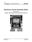
One Jake Brown Road Old Bridge, NJ 08857-1000 USA (800) 523-6049 • (732) 679-4000 • FAX: (732) 679-4353 www.blondertongue.com INSTRUCTION MANUAL HE-12/HE-4 Modular Headend Chassis Model Stock No. Description MIRC-12V MIRC-4D MIRC-4CUBE-CH 7715 7711 7703 Chassis Chassis Chassis Modular Headend Products Model Stock No. Description MIPS-12C MIRC-4CUBE-PS AMCM-860B AMCM-860HB AMCM-860S AMCM-860HS MICM-45C MICM-45S MIDM-806C DHDC-DV DHDC-DH DHDC-UV DHDC-UH AMM-806 MSBC 7722C 7702 7766B 7766HB 7766S 7766HS 7797C 7797S 7740C 6264A 6261A 6265A 6262A 7763 7727 Power Supply Power Supply Agile Modulator Agile Modulator (Horizontal) Stereo Agile Modulator Stereo Agile Modulator (Horizontal) A/V Modulator Stereo A/V Modulator Demodulator Digital High Definition Downconverter (Vertical) Digital High Definition Downconverter (Horizontal) Digital High Definition Upconverter (Vertical) Digital High Definition Upconverter (Horizontal) Agile Micro Modulator Sub-Band Block Converter 651204500J ©2009 Blonder Tongue Laboratories, Inc. All rights reserved. Specifications are subject to change without notice. Trademarks are the property of their respective owner. 2 HE-12/HE-4 Instruction Manual We recommend that you write the following information in the spaces provided below. Purchase Location Name: Purchase Location Telephone Number: Serial Number: The information contained herein is subject to change without notice. Revisions may be issued to advise of such changes and/or additions. Correspondence regarding this publication should be addressed directly to: Blonder Tongue Laboratories, Inc. One Jake Brown Road Old Bridge, NJ 08857 Document Number: 651204500J Printed in the United States of America. All product names, trade names, or corporate names mentioned in this document are acknowledged to be the proprietary property of the registered owners. This product incorporates copyright protection technology that is protected by U.S. patents and other intellectual property rights. Reverse engineering or disassembly is prohibited. HE-12/HE-4 Instruction Manual Table of Contents SECTION 1 – GENERAL & SAFETY INSTRUCTIONS........................................................................................................ 4 SECTION 2 – PRODUCT SUMMARY............................................................................................................................... 6 2.1 REVISION HISTORY & REASON....................................................................................................................................... 6 2.2 PRODUCT APPLICATION & DESCRIPTION....................................................................................................................... 6 2.3 PRODUCT SPECIFICATION.............................................................................................................................................. 7 SECTION 3 – INSTALLATION & POWER-UP................................................................................................................... 8 3.1 UNPACKING.................................................................................................................................................................... 8 3.2 INSTALLATION................................................................................................................................................................. 8 3.2 POWER-UP..................................................................................................................................................................... 8 SECTION 4 – QAM OUTPUT CONFIGURATION............................................................................................................. 9 4.1 GENERAL........................................................................................................................................................................ 9 4.2 QUICK CONFIGURATION............................................................................................................................................... 10 4.3 ADVANCED CONFIGURATION........................................................................................................................................ 11 4.3.1 ASI INPUT MODULE.................................................................................................................................................................11 4.3.2 8VSB/QAM INPUT MODULE....................................................................................................................................................12 4.3.2.1 Configuring for 8vsb input.................................................................................................................................12 4.3.2.2 Configuring for QAM Input.................................................................................................................................13 4.3.3 QAM MENU Options..............................................................................................................................................................14 4.3.4 RF OUTPUT MENU Options....................................................................................................................................................15 SECTION 5 – frequently asked questions........................................................................................................... 17 APPENDIX A: CATV CHANNEL FREQUENCY CHART.................................................................................................... 19 3 4 HE-12/HE-4 Instruction Manual General & Safety Instructions The STOP sign symbol is intended to alert you to the presence of REQUIRED operating and maintenance (servicing) instructions that if not followed, may result in product failure or destruction. The YIELD sign symbol in intended to alert you to the presence of RECOMMENDED operating and maintenance (servicing) instructions. The LIGHTNING flash symbol is intended to alert you to the presence of uninsulated "dangerous voltage" within the product's enclosure that may be sufficient magnitude to constitute a risk of electrical shock. TO REDUCE THE RISK OF ELECTRICAL SHOCK, DO NOT REMOVE COVER FROM THIS UNIT. NO USER-SERVICEABLE PARTS INSIDE. REFER SERVICING TO QUALIFIED SERVICE PERSONNEL. WARNING: TO PREVENT FIRE OR SHOCK HAZARD, DO NOT EXPOSE THIS UNIT TO RAIN OR MOISTURE NOTE TO CATV SYSTEM INSTALLER This reminder is provided to call the CATV System Installer’s attention to Article 820-40 of the NEC that provides guidelines for proper grounding and, in particular, specifies that the cable ground shall be connected to the grounding system of the building, as close to the point of cable entry as practical. Safety Instructions You should always follow these instructions to help ensure Against injury to yourself and damage to your equipment. ➥ Read all safety and operating instructions before you operate the unit. ➥ Retain all safety and operating instructions for future reference. ➥ Heed all warnings on the unit and in the safety and operating instructions. ➥ Follow all installation, operating, and use instructions. ➥ Unplug the unit from the AC power outlet before cleaning. Use only a damp cloth for cleaning the exterior of the unit. ➥ Do not use accessories or attachments not recommended by Blonder Tongue, as they may cause hazards, and will void the warranty. ➥ Do not operate the unit in high-humidity areas, or expose it to water or moisture. ➥ D o not place the unit on an unstable cart, stand, tripod, bracket, or table. The unit may fall, causing serious personal injury and damage to the unit. Install the unit only in a mounting rack designed for 19” rack-mounted equipment. HE-12/HE-4 Instruction Manual Safety Instructions - continued ➥ D o not block or cover slots and openings in the unit. These are provided for ventilation and protection from overheating. Never place the unit near or over a radiator or heat register. Do not place the unit in an enclosure such as a cabinet without proper ventilation. Do not mount equipment in the rack space directly above or below the unit. ➥ O perate the unit using only the type of power source indicated on the marking label. Unplug the unit power cord by gripping the plug, not the cord. ➥ T he unit is equipped with a three-wire ground-type plug. This plug will fit only into a ground-type power outlet. If you are unable to insert the plug into the outlet, contact an electrician to replace the outlet. Do not defeat the safety purpose of the ground-type plug. ➥ R oute power supply cords so that they are not likely to be walked on or pinched by items placed upon or against them. Pay particular attention to cords at plugs, convenience receptacles, and the point where they exit from the unit. ➥ B e sure that the outdoor components of the antenna system are grounded in accordance with local, federal, and National Electrical Code (NEC) requirements. Pay special attention to NEC Sections 810 and 820. See the example shown in the following diagram: ➥ W e strongly recommend using an outlet that contains surge suppression or ground fault protection. For added protection during a lightning storm, or when the unit is left unattended and unused for long periods of time, unplug it from the wall outlet and disconnect the lines between the unit and the antenna. This will prevent damage caused by lightning or power line surges. ➥ D o not locate the antenna near overhead power lines or other electric light or power circuits, or where it can fall into such power lines or circuits. When installing the antenna, take extreme care to avoid touching such power lines or circuits, as contact with them can be fatal. ➥ Do not overload wall outlets or extension cords, as this can result in a risk of fire or electrical shock. ➥ N ever insert objects of any kind into the unit through openings, as the objects may touch dangerous voltage points or short out parts. This could cause fire or electrical shock. ➥ D o not attempt to service the unit yourself, as opening or removing covers may expose you to dangerous voltage and will void the warranty. Refer all servicing to authorized service personnel. ➥ Unplug the unit from the wall outlet and refer servicing to authorized service personnel whenever the following occurs: ❏ The power supply cord or plug is damaged; ❏ Liquid has been spilled, or objects have fallen into the unit; ❏ The unit has been exposed to rain or water; ❏ The unit has been dropped or the chassis has been damaged; ❏ The unit exhibits a distinct change in performance. ➥ W hen replacement parts are required, ensure that the service technician uses replacement parts specified by Blonder Tongue. Unauthorized substitutions may damage the unit or cause electrical shock or fire, and will void the warranty. ➥ U pon completion of any service or repair to the unit, ask the service technician to perform safety checks to ensure that the unit is in proper operating condition. Returning Product for Repair (or Credit) A Return Material Authorization (RMA) Number is required on all products returned to Blonder Tongue, regardless if the product is being returned for repair or credit. Before returning product, please contact the Blonder Tongue Service Department at 1-800-523-6049, Ext. 4256 or visit our website: www.blondertongue.com for further information. 5 HE-12/HE-4 Instruction Manual Modular Headend Chassis MIRC-12V Description The MIRC-12V is a professional quality modular headend system designed to maximize rack space. The 2 RU MIRC-12V chassis will house up to 12 single width modules and one MIPS-12C power supply. Modular components consist of modulators and demodulators. These modular components are fully shielded and are field installable. The MIRC-12V chassis allows the compact modules to be added from the front of the chassis without removing the chassis from the rack. Field service and channel upgrades are plug and play. The MIRC-12V chassis is fully compatible with all MICM, MIDM, AMCM and DHDC series units. MIRC-12V Chassis MIRC-12V Specifications Mechanical Dimensions (W x H x D): 19 x 3.5 x 7.5 inches Weight: 1.1 lbs (0.5 kg) CH RF A/V 65 POWER VIDEO AUDIO MICM-c BLONDER TONGUE CH RF A/V 65 POWER VIDEO AUDIO MICM-c BLONDER TONGUE CH RF A/V 65 POWER VIDEO AUDIO MICM-c BLONDER TONGUE CH RF A/V 65 POWER VIDEO AUDIO MICM-c MIRC-4D Description The 1RU MIRC-4D chassis includes the modular power supply and holds up to four modules. The chassis (Stock No. 7711) is compatible with all modules. BLONDER TONGUE 6 MIRC-4D MIRC-4D Specifications General Power Requirements: 100 VAC to 240 VAC Frequency: 50 to 60 Hz Temperature Range: 0° to +50° C Output Voltage & Current Capacity: +12 VDC @ 1.8 Amps + 5 VDC @ 1.8 Amps Mechanical Dimensions (W x H x D) : 19 x 1.75 x 8.0 inches Weight: 3 lbs (1.4 kg) Connectors/Impedance AC Input: IEC DC Output: 4 sets of cables Accessories Supplied AC Power Cable, 6 ft., IEC, USA MIRC-4D HE-12/HE-4 Instruction Manual MIRC-4CUBE-CH Description The MIRC-4CUBE-CH is a standalone version of the MIRC-4. It can be used in any installation where modulators are required and no standard headend rack is available. The CUBE system consists of a chassis (MIRC-4CUBE-CH), power supply (MIRC-4CUBE-PS) and any combination of up to four modules. MIRC-4CUBE-CH Specifications Dimensions (W x H x D): 7.25 x 6.625 x 7.75 inches Weight: 6.0 lbs MIRC-4CUBE-PS Specifications General Power Requirements: 120 VAC to 240 VAC Frequency: 50 to 60 Hz Temperature Range: 0° to +50° C Output Voltage & Current Capacity: +12 VDC @ 1.8 Amps + 5 VDC @ 1.8 Amps MIRC-12V Chassis with MIPS-12C Power Supply Specifications MIPS-12C (Stock #7722C) (Typical) General Power Requirements: 100 VAC to 250 VAC Frequency: 50 to 60 Hz Temperature Range: 0° to +50° C Output: +5 VDC @ 5.5 Amps, +12 VDC @ 4 Amps Mechanical Dimensions (W x H x D) : 4.16 x 3.5 x 7.50 inches Weight: 1.10 lbs (0.50 kg) Connectors/Impedance AC Input: IEC DC Output: 37 pin D Indicators Power 1 ON: LED, green Accessories Supplied AC Power Cable: 6 Ft, IEC, USA MIPS-12C Power Supply Connections All the connectors on the power supply are located on the rear panel. 1. AC INPUT - The power supply accepts standard 100 to 250 VAC inputs. 2.DC Output - The polarized D connector provides 12 sets of +12 VDC, +5 VDC and ground cables for the modules. 1 2 7 8 HE-12/HE-4 Instruction Manual AMCM-860B MHz Agile Micro Modulator Description The AMCM-860B is a professional quality agile audio/video modulator with an output frequency range of 54-860 MHz. It joins Blonder Tongue’s impressive family of modular headend components and works in conjunction with the MIRC-4D and MIRC-12V rack chassis, MIRC-4CUBE-CH and MIPS12C power supply. The unit provides a modulated aural & visual carrier on any channel in the 54 to 860 MHz range. Frequency plans including Standard CATV, IRC, HRC and Broadcast are accommodated via front panel selection. Channel tuning is easily accomplished with the use of front panel switches following the entry instructions. All channels with appropriate FCC offsets are pre-programmed and tuned electronically via microprocessor. Features • Supports all Broadcast and CATV channels, including HRC and IRC assignments from 54 to 860 MHz. • Meets FCC docket 21006 aeronautical frequency response offset requirements • Front panel access to all level controls and indicators • Integrated stereo encoder available • Die-cast chassis offers superior RFI protection The AMCM-860 dissipates twice the wattage in comparison to other Blonder Tongue HE-12 modulators and demodulators. Due to this wattage increase, care must be taken when installing AMCM-860’s into an existing MIRC-12 configured with MIPS-12 power supplies (Stock No. 7722 or 7722B). These power supplies can only support one (1) AMCM-860. Installing more than one AMCM-860 will cause the power supply to fail. Should two (2) or more AMCM’s be required, the power supply must be changed to the new MIPS-12C (Stock #7722C) power supply. The “C” version power supply can easily be identified by the presence of fan vents on the front panel. A further enhancement to our HE Series product line is the MIRC-12V (Stock #7715) chassis. It is designed to provide increased ventilation for improved heat dissipation. HE-12/HE-4 Instruction Manual Specifications AMCM-860B (Typical) RF Frequency Range: 54-860 MHz Channels: CATV, VHF, UHF (STD, HRC, IRC) FCC Offset (pre-programmed): 0, +12.5, or 25 kHz Output Level - Min: +45 dBmV Output Level Adjust: 15 dB Aural/Visual Carrier Ratio: -10 to -17 dB Visual Carrier Frequency Tolerance Standard Channels: ±5 kHz FCC Aeronautical Channels: ±3 max kHz 4.5 MHz Aural Inter Carrier Frequency: ±150 Hz Channel Selectivity: Adjacent Aural and Below: -40 dB Adjacent Picture and Above: -50 dB Spurious Outputs: -60 dBc C/N Ratio In Channel: 65 dB Broadband Noise: -76 dBc Output Impedance: 75 Ω Output Return Loss: 12 dB Video Input Level: 1.0 V p-p Frequency Response fv-0.5 MHz to fv+4.2 MHz: ±1.0 dB P-P Video to RMS Hum Ratio: 65 dB Video Signal-to-Noise Ratio, NTC-7 Weighted: 62 dB Differential Gain: 2.0 % Differential Phase: 1.0 ° Over Modulation Indicator: 87.5, ±2.5 % Input Impedance: 75 Ω Input Return Loss: 24 min, dB Audio Input Level: 140 mV RMS minimum Input Impedance: 10k Ω, Unbalanced Total Harmonic Distortion (%): 1.0 Stereo Separation (AMCM 860S): 50 Hz - 100 Hz: 15 dB 100 Hz - 1 khz: 25 dB 12 kHz: 18 dB General Power Requirement: 5 W Voltage: 12 VDC @ 280 mA 5 VDC @ 470 mA Temperature Range: 0 to +50 ° C Mechanical Dimensions (W x H x D): 1.15 x 3.5 x 7.5 in. 29 x 89 x 191 mm Weight: .8 lbs., .36 kg Connectors Video Input: "F" Female L/R Audio Input: RCA Phono (2) RF Output: “F” Female Controls Channel Selection: Push-Button Switches, UP/DOWN Video Level: Control A/V Ratio: Control Audio Level: Control RF Output Level: Control Channel Enter: Push Button Indicators Channel Indicator: 2 Digit LED, Red Video Over Modulation: LED, Red Audio Over Modulation: LED, Red Stereo Indicator: LED, Green 9 10 HE-12/HE-4 Instruction Manual Operating Controls and Indicators 9 3 1. Stereo Indicator - Lit when video and stereo Front Panel 1 4 audio are present. UP CHANNEL ENT VIDEO 2.Audio/Video Ratio Adjustment STEREO Adjustment of the A/V Ratio is permitted RF AUDIO A/V from approximately -17 dB (full clockwise Level DN AMCM-860H position) to approximately -10 dB (full counterclockwise position) by rotating the 26 5 8 7 10 potentiometer. 3.Video Adjustment - Adjustment of the Video Modulation Level is permitted by rotating the potentiometer. 4. Video Over Modulation LED Indicator 5.Audio Adjustment - Adjustment of the Audio Modulation Level is permitted by rotating the potentiometer. 6.Audio Over Modulation LED Indicator 7. Up/Down Buttons - Used to set the desired channel or mode. 8. +100 Indicator - Lights when channel settings are 100 -135. 9.Channel ENT Button - Enter button used to enter a desired channel or mode. 10. RF Level Adjustment - Potentiometer adjustment used to set the output level. Has a range of 15 dB, optimum performance with a 10 dB adjustment. 11. Video Input - “F” Connector 12. Right Stereo Audio In - RCA Connector 13. Left Stereo Audio or Mono In - RCA Connector 14. Power Connector 15. RF Output - “F” Connector +100 Front Panel AMCM A/V 2 860 STEREO 4 6 AUD VID 5 DN UP CH 8 1 +100 ENT RF Level 3 7 9 10 Rear Panel VIDEO IN 11 STEREO RIGHT 12 AUDIO IN LEFT MONO P O W E R 13 14 15 It is strongly recommended to use the Blonder Tongue MIPS-12C or the MIRC-4D power supplies with the AMCM-860. It is also recommended to use the optional headend fan unit (QTHF, Stock No. 6235) when deploying more than 6 AMCM860 units in the MIRC-12V chassis. A rack space above and below the chassis unit is suggested for heat dissipation and air flow. RF OUT Programming the Unit The AMCM unit comes factory set to operate in the Standard CATV mode. The unit has 4 valid operating modes: STD CATV, IRC, HRC & Broadcast UHF/VHF. (Skip to the next section for programming the operating mode) Programming a Channel 1. N avigate to the desired channel number by depressing the p UP and q DN buttons. a. Continuous past 99 for channels 100-135, the +100 red LED will illuminate. 2. P ress ENTER when you reach the desired channel setting. This will tune the modulator output to the corresponding channel frequency for this entry. a. The LED display will blink continuously during the channel programming process and will not change the output frequency the unit is programmed until ENTER is depressed. b. T he unit has a special feature that alerts an operator of an inadvertent or desired change to the channel display by flashing the LED readout. The LED display will continue to flash for 30 seconds if ENTER is not depressed and then will return to the display of the previously programming channel entry setting. HE-12/HE-4 11 Instruction Manual Operating Mode Selection The unit has 4 valid operating modes: STD CATV, IRC, HRC & Broadcast UHF/VHF. The AMCM unit comes factory set to operate in the Standard CATV mode. To change the operating mode: 1. Simultaneously depress p UP and q DN for approximately 5 seconds. 2. The Channel LED display will switch to the operating mode selection. 3. Use p UP or q DN to select the desired mode: a. C = STD CATV b. H = HRC c. I = IRC d. U = Broadcast (VHF/UHF) 4. After selecting the desired mode depress ENTER to set the mode. 5. The unit will return to the channel display mode. a. Programming will reflect the mode chosen – See Appendix A for a detailed frequency plan. b. The programming mode will also flash continuously during the programming process. The LED display will continue to flash for 30 seconds if ENTER is not depressed and then will return to the display of the previously programming channel and mode entry setting. Jumper 2 3 2 1 JUMPER SETTINGS MONO Stock No. 7766B J2 - PIN 2-3 J6 - PIN 2-3 J7 - PIN 2-3 Ö Pin 1 2 3 1 2 3 Jumper 7 Jumper 6 Jumpers 9, 11 & 10 Stereo PCB STEREO Stock No. 7766S J2 - PIN 1-2 J6 - PIN 1-2 J7 - PIN 1-2 Internal Jumper Settings - AMCM-860B Troubleshooting - AMCM-860 A continuous flashing CH Display indicates a Error Condition detected by the unit microcontroller. Sample conditions include: • Channel Selector Entry does not match the channel number on which the modulator is operating, the display will flash for 30 seconds and then revert back to the previous CH entry. • E1 is displayed if the Input & VCO is Not Locked • E2 is displayed if the Output VCO is Not Locked Possible Error Condition Scenarios 1. An Error Condition may occur when a channel number was accidentally altered by changing the push button switch to a number that is different from the output channel set in memory, or if there was a switch malfunction. 2. An Error Condition may occur when a user sets a new mode and the previously programmed channel is not in the new mode’s channel range. SEE APPENDIX A FOR A COMPLETE LIST OF AVAILABLE CHANNELS. STD CATV; IRC & HRC 1-135 and BROADCAST 2-69 Correction Suggestions The User should perform the following steps to correct an Error Condition: 1. Check that the Channel Display is set to the desired channel and reset as appropriate 2. Check that the unit is set to the appropriate desired operating mode 3. Verify the unit output on a spectrum analyzer 4. Disconnect and reconnect power to the unit If an error condition continues to be displayed, unit should be replaced and serviced. 12 HE-12/HE-4 Instruction Manual MICM-45 Modulators Description The MICM-45 is a professional quality, channelized, heterodyne audio/video modulator. The unit provides modulated RF carrier output on any single VHF channel, including: broadcast TV (2-13), CATV (14-135). The MICM-45 is ideal for placing audio and video onto any unused VHF channel. Any standard audio/video source can be used, such as satellite receivers, television cameras, video tape recorders, or television demodulators. The MICM-45 utilizes SAW filtering with FCC group delay pre-distortion to provide true vestigial sideband selectivity. This makes the MICM-45 perfect for use in adjacent channel systems. The MICM-45C takes baseband audio and video and modulates these signals onto the desired output channel. The MICM45S takes baseband L/R audio and video and modulates these signals into the desired output channel. The heterodyne conversion process used in the MICM-45 employs a crystal referenced, PLL synthesized local oscillator. This guarantees rock solid, no-drift output for the life of the modulator. The MICM-45 meets FCC Docket 21006 aeronautical frequency offset requirements (±5 kHz video carrier accuracy). The modulator accepts standard polarity (sync negative) video in the range of 0.7 to 2.5 V p-p. The MICM-45C has field defeatable audio pre-emphasis to provide stereo compatibility with any external BTSC stereo generator providing a composite stereo baseband output. The MICM-45S is a stereo A/V modulator providing a stereo audio and video modulated RF carrier on any single VHF channel. All other features and specifications are identical to the MICM-45C except as noted below. Specifications MICM-45 (Typical) RF Frequency Range: 54-860 MHz (Broadcast 2-13, Cable 14-135) Output Level: +45 dBmV Output Level Range: 10 dB continuously adjustable Aural/Visual Carrier Ratio: -11 to -19 dB continuously adjustable Visual Carrier Frequency Tolerance: ±10 kHz (standard channels) ± 5 kHz (aeronautical channels) Aural Carrier: 4.5 MHz above visual Frequency Setting: ±1.5 kHz Spurious Outputs: -60 dBc, minimum C/N Ratio In Channel: 60 dB Broadband Noise: -90 dB Output Return Loss: 12 dB IF (Internal) Frequency: 45.750 MHz Video Input Level: 1.0 V p-p for 87.5 % modulation Frequency Response fv -0.5 MHz to fv +4.2 MHz: ±1.0 dB Video C/N: 60 dB (4 MHz BW) P-P Video to RMS Hum Ratio: 60 dB Differential Gain: ±4.0 % @ 87.5% Modulation Differential Phase: ± 2° @ 87.5% Modulation Input Return Loss: 18 dB Audio Input Level: 140 mV RMS for 25 kHz peak deviation Input Impedance: 10k Ohm, unbalanced Frequency Range: 20 Hz to 20 kHz (MICM-45C) Frequency Response: ±1.0 dB, (50 Hz to 12 kHz) Reference to Std. 75 µs Pre-emphasis (MICM-45C) ± 0.3 dB (50 Hz to 50 kHz) (MICM-45S) in Stereo Configuration w/o pre-emphasis Total Harmonic Distortion (%): 1.0 at 25 kHz Deviation Stereo Separation (MICM-45S): 50 Hz - 100 Hz: 15 dB 100 Hz - 1 kHz: 25 dB 12 kHz: 18 dB Aural Intercarrier: ±5 kHz (0° to +50° C), std. General Power Requirements External: +12 VDC @ 160 mA +5 VDC @ 130 mA (MICM-C) +5 VDC @ 180 mA (MICM-S) Temperature Range: 0° to +50° C Mechanical Dimensions (W x H x D): 1.2 x 3.5 x 7.5 inches Weight: 0.65 lbs (0.30 kg) Connectors/Impedance Audio Input: RCA Phono, female (MICM-45C) L/R Audio Inputs: RCA Phono, female Video Input: 75 ohm “F” type, female RF Output: 75 ohm “F” type, female Power: 3 Pin Header Controls Video Level: Pot Audio Level: Pot Aural Carrier Level: Pot RF Output Level: Pot Indicators Power ON: LED, green Video Over Modulation: LED, red (MICM-45S) Audio Over Modulation: LED, red (MICM-45S) Stereo Indicator: LED, red (MICM-45S) HE-12/HE-4 13 Instruction Manual Operating Controls and Indicators - MICM-45 Front Panel All operating controls are located on, or are accessible from the front panel. 1.Audio - Adjusts the aural carrier modulation. 1A Audio - Aural carrier modulation control/overmodulation indicator. 2. Stereo Indicator 3.Video - Adjusts the modulation percentage. 3AVideo - Modulation control/overmodulation indicator. 4.Power - The green LED indicates power is present and the fuse is good. 5.A/V - Controls the amplitude of aural RF carrier to change aural/visual ratio. 6.Channel - The modulator is factory aligned to the channel number indicated. 7. RF - The RF pot simultaneously adjusts the amplitude of aural and visual carriers to the final drive amplifier. BLONDER TONGUE MICM-c BLONDER TONGUE 1 MICM-s 2 AUDIO AUDIO 3 VIDEO 4 POWER 5 VIDEO POWER A/V 65 CH 1A 3A A/V 7 RF 65 CH RF 6 Rear Panel All the connectors on the Modulator are located on the rear panel. 1. Video Input - The modulator accepts standard negative sync video at a 0.7 to 2.5 Vp-p level. 2.Audio Input - The modulator accepts 140 mV RMS for 25 kHz peak deviation (MICM-C). Left audio input for MICM-S only. 3. Power - The polarized power connector accepts +12 VDC +5 VDC and ground. 4. Right Audio Input for MICM-S only. Connector not used in MICM-C (capped) 5.RF Out - The filtered RF signal is available for connection to a headend combiner. 1 2 3 4 5 Pre-emphasis Jumper Position 1-2 = Stereo Postion 2-3 = Mono STEREO 1 2 Position 1-2 = Disable Postion 2-3 = Enable MONO DISABLE 3 1 ENABLE 2 3 DC Input +5 V +12 V GND Internal Jumper Settings MICM-45C comes factory set for audio pre-emphasis enabled. 14 HE-12/HE-4 Instruction Manual Internal Jumper Settings - MICM-45B MICM-45B comes factory set for audio pre-emphasis enabled. There are three (3) MICM-45B PC Board layout revisions available. Choose the applicable one from the diagrams below. 1 2 JP 1 3 VIDEO IN 2 1 JP 2 Jumper 1 - Audio Pre-Emphasis SettingJumper 2 - Not Used 1 1-2 position = Enabled . . . 2 2-3 position = Disabled . . . 1 2 3 1 2 3 Jumper must be set to 1-2 position. . . Pre-emphasis Jumper Enable 2 1 Disable 3 1 1 2 2 3 3 Pre-emphasis Jumper Position 1-2 = Stereo Postion 2-3 = Mono STEREO 1 2 Position 1-2 = Disable Postion 2-3 = Enable MONO DISABLE 3 1 ENABLE 2 3 1 2 1 2 3 1 2 3 HE-12/HE-4 15 Instruction Manual AMM-806 — Agile Micro Modulator Description The AMM-806 is an economical CATV agile audio/video modulator. It joins Blonder Tongue's family of modular headend components and works in conjunction with the MIRC-12V rack chassis and MIPS-12C power supply. It covers channel frequencies between 54-806 MHz. Channel selection is done by easy to use front panel DIP switches. FCC frequency offsets per Docket 21006 are automatic via the units internal pre-programmed micro processor. The AMM-806 accepts standard audio/video sources such as satellite receivers, television camera, video tape recorders or demodulators. The advanced design ensures access for all level and over-modulation controls via the front panel. The audio pre-emphasis can be disabled internally for use with a BTSC Stereo Encoder. RF CATV Frequency Range: AMM-806 (CH 2-125) Output Level - Min: 35-45 dBmV, Continuously Variable Aural/Visual Carrier Ratio: -12 to -18 dB Visual Carrier Frequency Tolerance Standard Channels: ±10 kHz FCC Aeronautical Channels (AMML Only): ±5 kHz 4.5 MHz Aural Inter Carrier Frequency: ±150 Hz (max) Spurious Outputs: -60 dBc C/N Ratio In Channel: 60 dB Broadband Noise: -75 dBc Output Impedance: 75 ohm Output Return Loss: 10 dB Video Input Level: 1.0 V p-p Frequency Response: fv-0.5 MHz to fv+4.2 MHz: ±1.0 dB Input Impedance: 75 ohm Input Return Loss: 18 dB min Differential Phase: 2.0° Differential Gain: 1.0% Group Delay Response: Meets FCC CATV Predistortion Requirements for Color Operation Audio Input Level: 0.4 to 4.0 V p-p Frequency Range: 30 Hz to 15 kHz, ± 0.5 dB (Exceeds 100 kHz with Pre-emphasis Defeated) Input Impedance: 10k ohm, Unbalanced Distortion: 30 Hz to 15 kHz 0.6% Setting up the AMM-806 Output Channel Channel setting is accomplished by setting the channel switch to the desired output channel. The switch is divided into 2 sections, the Tens section (denoted as "X") and the Ones section (denoted as "Y"). In each section, there are 4 switches labeled - 8,4,2,1. This corresponds to the switch value. Setting the switch to the right invokes the corresponding value of the switch. The user sets the Tens section and the Ones section to reflect the desired channel. (i.e., For CH 116, you set 11 Tens and 6 ones for 116. For single digit channels, the Tens switch is set to zero.) General Power Requirements Voltage: +12 VDC @ 155mA Power: +5 VDC @ 265mA Temperature: 0° to 50° C Mechanical Dimensions (W x H x D): 1.15 x 3.5 x 7.5 in., 29 x 89 x 191 mm Weight: 0.8 lbs, 0.36 kg Connectors (Rear Panel) Video Input: “F” Type, Female Audio Input: RCA Phono RF Output: “F” Type Female Power: 3 Pin Header Controls (Front Panel) Channel Selection: Dip Switches Video Level: Control A/V Ratio: Control Audio Level: Control RF Output Level: Control Indicator (Front Panel) Power ON: LED AMM - 806 X = 11 Y=6 8 4 2 1 8 4 X=8 Y=4 8 4 2 1 8 4 2 2 1 1 XY = ch.116 XY = ch. 84 Examples of switch settings for various channels 16 HE-12/HE-4 Instruction Manual MSBC - Sub-Band Block Converter Description The MSBC is a modular sub band block up-converter designed for use in Blonder Tongue’s HE Series rack chassis’. The unit provides sub-band capability to MIDM-806C demodulators by block converting sub-band channels T7 to T13 to receivable VHF channels 7 to13. The MIDM-806C A/V outputs can then be connected to a modulator such as a MICM-45C, AMCM 860 or AMM Series for a complete modular headend processing solution. Specifications (Typical) RF Input Frequency Range: 5.75-47.75 MHz (Channels T7-T13) Output Frequency Range: 174-216 MHz (Channels 7-13) Recommended Input Level Range: 0 to +20 dBmV Conversion Gain: 3 dB Flatness: 1.5 dB P/V LO Frequency accuracy @ 25 deg. C: +/- 500 Hz Intermod Distortion: -60 dBc (In band Ch. 7-13 @ 0 to + 20 dBmV input) Input/Output Impedance: 75 Ohm Return Loss: Input: 15 dB/ Output: 17 dB Mechanical Dimensions: 1.15 x 3.5 x 7.5 in. Weight: 13.5 oz. Temperature Range: 0 to 50 degrees C Connectors (Rear) Sub-Band Input: “F” Type Female RF Output: “F” Type Female Power: 3 Pin Header Indicators (Front) Power Green LED Electrical +12 VDC, 100 mA 1.2 Watts Front Panel MSBC BLONDER TONGUE MSBC Return Channel(s) From Sub-Band Diplexer Ch.T7-T13 MICM AMCM AMM MIDM SUB-BAND INPUT VIDEO OUT VIDEO IN NOT USED AUDIO OUT AUDIO IN POWER POWER POWER RF IN RF OUT 65 POWER INDICATOR RF OUTPUT Sub-Band Converter Demodulator INPUT LO FREQ. Channel Frequency T7 T8 T9 T10 T11 T12 T13 7 MHz 13 MHz 19 MHz 25 MHz 31 MHz 36 MHz 43 MHz Modulator Channel 168.25 MHz 168.25 MHz 168.25 MHz 168.25 MHz 168.25 MHz 168.25 MHz 168.25 MHz 7 8 9 10 11 12 13 OUTPUT Frequency 175.25 MHz 181.25 MHz 187.25 MHz 193.25 MHz 199.25 MHz 205.25 MHz 211.25 MHz é Forward Output Channel to Combiner HE-12/HE-4 17 Instruction Manual MIDM-806C Demodulators Description The MIDM-806C is a professional quality single channel, agile audio/video demodulator. It provides an A/V output from any VHF, UHF or CATV channel (54-806 MHz) and is designed for use in the Blonder Tongue Modular Headend System. The MIDM-806C demodulator and an MICM/AMCM modulator can be paired to perform off-air channel processing or to cherry pick cable channels. ☛ Note: A MIPS-12C, (Stock #7722C) Power Supply is required for full chassis deployment. The MIDM-806C can demodulate any single Broadcast or CATV, VHF & UHF channel in the 54 to 806 MHz frequency range. It is ideal for off-air signal processing (audio/video processing and remodulation) and CATV cherry picking applications. The MIDM-806C series features rock solid, phase lock loop (PLL) synthesized frequency control. Agile frequency selection is accomplished via front panel channel up/down buttons with a LED channel readout for easy on-the-fly channel changes. A channel lockout mode is also provided to prevent accidental channel changes. Non-volatile memory maintains the programmed channel selection in case of power loss. All MIDM series units are compatible with any modulators requiring a baseband input, and can be used in any combination with the MIPS-12C power supply in a MIRC-12V chassis. Specifications MIDM-806C (Typical) RF Frequency: Range: 54-806 MHz, VHF, UHF, CATV (Std., IRC, HRC) Input Level Range: -5 to +30 dBm VHF/UHF, +2 to +12 dBmV (CATV) Noise Figure: 8 dB Image Rejection: VHF 60 dB Input Impedance: 75 ohm Video Output Level: 1.0 V p-p Output Impedance: 75 ohm Audio Output Level: 1 Vp-p Output Impedance: 600 ohm, unbalanced General Power Requirements - External: +12 VDC @ 140 mA, 5 VDC @ 150 mA Temperature Range: 0° to +50° C Mechanical Dimensions (W x H x D): 1.0 x 3.5 x 7.5 inches Weight: 1.2 lbs (0.56 kg) Connectors/Impedance Audio Output: RCA Phono, female Video Output: 75 ohm “F” type, female RF Input: 75 ohm “F” type, female Power: Locking Header, 3 pin Controls Channel Selection: Push buttons ANT/CATV: Push button Power On/OFF: Push button Channel Lock: Push button Audio Level: Pot Video Level: Pot Indicators Channel: 2 digit, 7 segment LED 18 HE-12/HE-4 Instruction Manual Operating Controls & Indicators - MIDM-806C Front Panel All operating controls are located on, or are accessible from the front panel. 1. 2. 3. 4. BLONDER TONGUE Video - Adjusts video output level Audio - Adjusts audio output level Channel LED - Displays ANT or CATV channel number C/ANT Mode Button - Push button to enter the mode selection menu. Use the channel Up/Down keys to select the type of channel system required as follows: MIDM-806C V Channel System STD CATV HRC IRC Broadcast U/V 5. 6. 7. 8. Power - On / Off push button Channel Down - Increments channel by -1 Channel Up - Increments channel by +1 +100 LED - When depressed, red LED lights to indicate channels 100 and higher 9. Lock - Depressing Lock button locks present channel or mode in memory preventing inadvertent change. A user must depress the lock button again for any channel mode/changes A . 5 Display 2 1 3 . Stock no. 7740C 4 PWR C/ANT CH CH LOCK +100 6 7 8 9 3. LED Display - Lights when in standby . . LOCK Indicator Channel Display Rear Panel All the connectors are located on the rear panel. 1. Video Output - Standard negative sync video at a 0.5 to 1.5 Vp-p level. 2. Audio Output - Adjustable 0.5 to 1.5 Vp-p 3. Power - The polarized power connector accepts +12 VDC +5 VDC and ground 4. ANT/CATV - RF input from antenna or CATV drop 1 2 3 4 DC Input +5 V +12 V GND HE-12/HE-4 19 Instruction Manual DHDP - Digital High Definition Processor Series DHDC-UH (Upconverter-Horizontal) • Stock No. 6262A DHDC-DV (Downconverter) • Stock No. 6264A DHDP-V - Vertical Combo Pack • Stock No. 6266B; (Combo: 6262A + 6265A) DHDC-UV (Upconverter) • Stock No. 6265A DHDC-DH (Downconverter-Horizontal) • Stock No. 6261A DHDP-H - Horizontal Combo Pack • Stock No. 6263A; (Combo: 6261A + 6262A) Description: The DHDP Series consists of 2 parts, the DHDC-D (Downconverter) and the DHDC-U (Upconverter). The units are intended to operate as a system in order to process digital & high definition television (HDTV) signals. Operating Controls and Indicators Front Panel 1. 2-Digit LED Display — 2 digit LED Channel display 2. Up/Down Channel Buttons — Up & down push button controls for setting the channel. 3. Enter Button - Button used to enter the displayed channel into memory. 4. Up/Down RF Level Buttons — Up & down push button controls for RF level. 5. Up/Down Channel Buttons — Up & down push button controls for channel and mode adjustment. 6. 2-Digit LED Display — 2 digit LED display for Channel, mode and RF level information. 7. Enter Button — Button used to “enter” channel, mode or RF level selection into memory. 8. +100 Channel LED Indicator — LED illuminates to indicate CATV channels 100 to 135. Front Panel Views DHDC-DV BLONDER TONGUE DHDC DHDC-UV -DV BLONDER TONGUE DHDC UP 4 RF LEVEL DN CHANNEL 2 UP 5 DN 1 UP RF LEVEL DHDC-UH UP CHANNEL 7 8 1 2 DHDC-DH BLONDER TONGUE 7 ENTER +100 DN 4 6 ENTER UP DN DIGITAL HDTV UP CONVERTER CH +100 6 5 BLONDER TONGUE DN 3 CH ENTER DHDC-UH -UV UP CHANNEL 8 3 ENTER DHDC-DH DIGITAL HDTV DOWN CONVERTER Rear Panel 9. IF Output - “F” Connector 10. IF Input - “F” Connector 11. Power Connector 12. RF Input - “F” Connector 13. RF Output - “F” Connector DN Rear Panel Views DHDC-DV/DH DHDC-UV/UH IF IF 10 9 POWER 11 POWER 12 RF Specifications DHDC-D Down Converter Input Tuning Range (Off-Air 8VSB) (54-216, 470-864 MHz) VHF: CH 2-13, UHF: CH 14-69, CH 70-78 Extended UHF Operating Input Level Range: -20 to +25 dBmV Installation Input Range: -15 to +20 dBmV (any undesired channel < +25 dBmV) Max undesired to desired channel ratio: < +25 dBc Max adjacent to desired channel ratio: < +15 dBc IF Output Level Digital: +30 dBmV* Rejection of Adjacent Analog Channels: -70 dB Typical Power Requirements: 110 mA @ +12 VDC, 370 mA @ +5 VDC 11 13 RF DHDC-U Up Converter IF Input Level: +30 dBmV Output Frequency Range: Standard CATV, IRC, HRC & Broadcast 54-864 MHz RF Output Level Digital: +45 dBmV* Display Error: ±2 dB Output Level Adjustment Range: +35 to +45 dBmV Spurious Output (54-864 MHz): -60 dBc Phase Noise @ 10 kHz Offset: -95 dBc/Hz Broadband Noise, Out of Channel: -70 dBc (5.5 MHz BW) Power Requirement: 310 mA @ +12 VDC, 320 mA @ +5 VDC * Average Measurement 20 HE-12/HE-4 Instruction Manual Setting Up the Units 1. Place each of the units into the appropriate Blonder Tongue Micromodular chassis by sliding the unit into the retaining rails. a. It is recommended to physically place one Downconverter and one Upconverter next to one another in the chassis. 2. Connect the digital or HDTV signal (8VSB format) to the RF ‘F’ connector on the DHDC-D unit. 3. Connect the IF ‘F’ connector of the DHDC-D to the IF ‘F’ connector of the DHDC-U. 4. Connect the RF ‘F’ connector of the DHDC-U to the appropriate combining device. 5. Connect each unit to the power supply using one of the power supply cables. Programming the Unit The DHDC-D unit is intended to accept any digital UHF or VHF signal and convert it to IF. The DHDC-U unit is intended to accept any digital IF signal and process it to any channel from 54-864 MHz. The unit has 4 valid operating modes, STD CATV, IRC, HRC & Broadcast UHF/VHF. It comes factory set to operate in Standard CATV Mode. If you wish to change the operating mode skip to the Operating Mode Selection section. Programming the DHDC-D 1. Navigate to the desired channel number by depressing the CH p UP and q DN buttons. a. Press and hold the CH p UP or q DN arrow button for fast scrolling. 2. Press the ENTER button when you reach the desired channel setting. This will tune the downconverter input to the corresponding frequency for this entry. a. The LED display will blink continuously during the channel programming process and will not change the channel until the ENTER button is depressed. b. The unit has a special feature that alerts an operator of an inadvertent or desired change to the unit by flashing LED readout. The LED will continue to flash for 30 seconds if the ENTER button is not depressed and if no additional entries are made then the readout will return to the display of the previously programmed channel entry setting. Programming the DHDC-U The DHDC-U unit comes factory set to operate in the Standard CATV mode. The unit has 4 valid operating modes: STD, CATV, IRC, HRC & Broadcast UHF/VHF (see the operating mode selection section for programming information). Programming a Channel 1. Navigate to the desired channel number by depressing the CH p UP and q DN buttons. a. Continue past 99 for channels 100-135, the +100 LED will illuminate. b. Press and hold the CH p UP or q DN arrow button for fast scrolling. 2. Press the ENTER button when you reach the desired channel setting. This will tune the upconverter output to the corresponding frequency for this entry. a. The LED display will blink continuously during the channel programming process and will not change the output channel until the ENTER button is depressed. b. The unit has a special feature that alerts an operator of an inadvertent or desired change to the unit by flashing LED readout. The LED will continue to flash for 30 seconds if the ENTER button is not depressed and if no additional entries are made then the readout will return to the display of the previously programmed channel entry setting. HE-12/HE-4 21 Instruction Manual Programming the DHDC-U (Continued) Programming RF Level 1. Depress the RF Level p UP or q DN buttons to increment or decrement the RF output level to the desired setting. a. The unit has a specified adjustment range of +35 dBmV to +45 dBmV output. The unit software however, will permit entries from +33 to +47 dBmV, the out of range entries of 33-34 & 46-47 dBmV are meant for usage to correct any display error, allowing the unit to be operated in the specified range. ATTENTION! It is also recommended to set the output level to +45 dBmV for optimum noise performance and externally attenuate down to a desired level. 2. P ress ENTER when you reach the desired RF Level setting. This will tune the upconverter output to the corresponding level entry. a. The LED display readout will also flash continuously during the RF Level programming process. The LED display will continue to flash for 30 seconds if ENTER is not depressed and then will return to the display of the previously programmed channel entry setting. Operating Mode Selection The unit has 4 valid operating modes: STD CATV, IRC, HRC & Broadcast UHF/VHF. The DHDC-U unit comes factory set to operate in the Standard CATV mode. To change the operating mode 1. Simultaneously depress the RF Level p UP and q DN buttons for approximately 5 seconds. 2. The Channel LED display will switch to the operating mode selection. 3. Use the RF Level p UP and q DN buttons to select the desired mode: a. C = STD CATV b. H = HRC c. I = IRC d. U = Broadcast (VHF/UHF) 4. After selecting the desired mode depress ENTER to set the mode. 5. The unit will return to the channel display mode. a. Programming will reflect the mode chosen – See Appendix for detailed frequency plans. b. The operating mode will also flash continuously during the mode selection process. The LED display will continue to flash for 30 seconds if ENTER is not depressed and then will return to the display of the previously programmed channel & mode entry setting. NOTE: THE MODE PRESENTLY IN MEMORY WILL BE DISPLAYED WITHOUT FLASHING DURING THE MODE SELECTION PROCESS. Trouble Shooting A continuously flashing Channel Display indicates an Error Condition detected by the unit microcontroller. Sample conditions include: Correction Suggestion The User should perform the following steps to correct an Error Condition: 1. Check that the Channel Display is set to the desired channel & reset as appropriate. •Channel Selector Entry does not match the channel number on which the unit is operating, the display will flash for 30 seconds and then revert back to the previous CH entry 3. Verify the unit output on a spectrum analyzer. • E1 is displayed if the Input VCO is Not Locked 4. Disconnect and reconnect power to the unit. • E2 is displayed if the Output VCO is Not Locked If an error condition continues to be displayed, unit should be replaced and serviced. 2. Check that the unit is set to the appropriate desired operating mode. 22 HE-12/HE-4 Instruction Manual Appendix A Frequency Allocation Tables EIA Chan. 02 03 04 01 05 06 95 96 97 98 99 14 15 16 17 18 19 20 21 22 07 08 09 10 11 12 13 23 24 25 26 27 28 29 30 31 32 33 34 35 36 37 38 39 40 41 42 43 44 45 46 47 48 49 50 51 52 53 54 55 56 57 58 59 60 61 62 Standard Video Incremental Video (IRC) Harmonic Video (HRC) 55.2500 61.2500 67.2500 NA 77.2500 83.2500 91.2500 97.2500 103.2500 109.2750 115.2750 121.2625 127.2625 133.2625 139.2500 145.2500 151.2500 157.2500 163.2500 169.2500 175.2500 181.2500 187.2500 193.2500 199.2500 205.2500 211.2500 217.2500 223.2500 229.2625 235.2625 241.2625 247.2625 253.2625 259.2625 265.2625 271.2625 277.2625 283.2625 289.2625 295.2625 301.2625 307.2625 313.2625 319.2625 325.2625 331.2750 337.2625 343.2625 349.2625 355.2625 361.2625 367.2625 373.2625 379.2625 385.2625 391.2625 397.2625 403.2500 409.2500 415.2500 421.2500 427.2500 433.2500 439.2500 445.2500 451.2500 55.2625 61.2625 67.2625 73.2625 79.2625 85.2625 91.2625 97.2625 103.2625 109.2750 115.2750 121.2625 127.2625 133.2625 139.2625 145.2625 151.2625 157.2625 163.2625 169.2625 175.2625 181.2625 187.2625 193.2625 199.2625 205.2625 211.2625 217.2625 223.2625 229.2625 235.2625 241.2625 247.2625 253.2625 259.2625 265.2625 271.2625 277.2625 283.2625 289.2625 295.2625 301.2625 307.2625 313.2625 319.2625 325.2625 331.2750 337.2625 343.2625 349.2625 355.2625 361.2625 367.2625 373.2625 379.2625 385.2625 391.2625 397.2625 403.2625 409.2625 415.2625 421.2625 427.2625 433.2625 439.2625 445.2625 451.2625 54 60 66 72 78 84 90 96 102 Cannot lock to comb ref: refer to FCC regs 120 126 132 138 144 150 156 162 168 174 180 186 192 198 204 210 216 222 228 234 240 246 252 258 264 270 276 282 288 294 300 306 312 318 324 330 336 342 348 354 360 366 372 378 384 390 396 402 408 414 420 426 432 438 444 450 EIA Chan. 63 64 65 66 67 68 69 70 71 72 73 74 75 76 77 78 79 80 81 82 83 84 85 86 87 88 89 90 91 92 93 94 100 101 102 103 104 105 106 107 108 109 110 111 112 113 114 115 116 117 118 119 120 121 122 123 124 125 126 127 128 129 130 131 132 133 134 135 NOTE: Refer to unit specifications for their respective operating ranges. Standard Video Incremental Video (IRC) Harmonic Video (HRC) 457.2500 463.2500 469.2500 475.2500 481.2500 487.2500 493.2500 499.2500 505.2500 511.2500 517.2500 523.2500 529.2500 535.2500 541.2500 547.2500 553.2500 559.2500 565.2500 571.2500 577.2500 583.2500 589.2500 595.2500 601.2500 607.2500 613.2500 619.2500 625.2500 631.2500 637.2500 643.2500 649.2500 655.2500 661.2500 667.2500 673.2500 679.2500 685.2500 691.2500 697.2500 703.2500 709.2500 715.2500 721.2500 727.2500 733.2500 739.2500 745.2500 751.2500 757.2500 763.2500 769.2500 775.2500 781.2500 787.2500 793.2500 799.2500 805.2500 811.2500 817.2500 823.2500 829.2500 835.2500 841.2500 847.2500 853.2500 859.2500 457.2625 463.2625 469.2625 475.2625 481.2625 487.2625 493.2625 499.2625 505.2625 511.2625 517.2625 523.2625 529.2625 535.2625 541.2625 547.2625 553.2625 559.2625 565.2625 571.2625 577.2625 583.2625 589.2625 595.2625 601.2625 607.2625 613.2625 619.2625 625.2625 631.2625 637.2625 643.2625 649.2625 655.2625 661.2625 667.2625 673.2625 679.2625 685.2625 691.2625 697.2625 703.2625 709.2625 715.2625 721.2625 727.2625 733.2625 739.2625 745.2625 751.2625 757.2625 763.2625 769.2625 775.2625 781.2625 787.2625 793.2625 799.2625 805.2625 811.2625 817.2625 823.2625 829.2625 835.2625 841.2625 847.2625 853.2625 859.2625 456 462 468 474 480 486 492 498 504 510 516 522 528 534 540 546 552 558 564 570 576 582 588 594 600 606 612 618 624 630 636 642 648 654 660 666 672 678 684 690 696 702 708 714 720 726 732 738 744 750 756 762 768 774 780 786 792 798 804 810 816 822 828 834 840 846 852 858 VHF Broadcast Channels Channel Video (MHz) 2 55.25 3 61.25 4 67.25 5 77.25 6 83.25 7 175.25 8 181.25 9 187.25 10 193.25 11 199.25 12 205.25 13 211.25 UHF Broadcast Channels Channel Video (MHz) 14 471.25 15 477.25 16 483.25 17 489.25 18 495.25 19 501.25 20 507.25 21 513.25 22 519.25 23 525.25 24 531.25 25 537.25 26 543.25 27 549.25 28 555.25 29 561.25 30 567.25 31 573.25 32 579.25 33 585.25 34 591.25 35 597.25 36 603.25 37 609.25 38 615.25 39 621.25 40 627.25 41 633.25 42 639.25 43 645.25 44 651.25 45 657.25 46 663.25 47 669.25 48 675.25 49 681.25 50 687.25 51 693.25 52 699.25 53 705.25 54 711.25 55 717.25 56 723.25 57 729.25 58 735.25 59 741.25 60 747.25 61 753.25 62 759.25 63 765.25 64 771.25 65 777.25 66 783.25 67 789.25 68 795.25 69 801.25 HE-12/HE-4 23 Instruction Manual Appendix B Appendix C DHDC-D Input & DHDC-U Output DHDC-U Center Frequencies Center Frequencies VHF Broadcast Channels Channel (MHz) 2 57 3 63 4 69 5 79 6 85 7 177 8 183 9 189 10 195 11 201 12 207 13 213 UHF Broadcast Channels Channel (MHz) 14 473 15 479 16 485 17 491 18 497 19 503 20 509 21 515 22 521 23 527 24 533 25 539 26 545 27 551 28 557 29 563 30 569 31 575 32 581 33 587 34 593 35 599 36 605 37 611 38 617 39 623 40 629 41 635 42 641 43 647 44 653 45 659 46 665 47 671 48 677 49 683 50 689 51 695 52 701 53 707 54 713 55 719 56 725 57 731 58 737 59 743 60 749 61 755 62 761 63 767 64 773 65 779 66 785 67 791 68 797 69 803 EIA Chan. Standard CATV 2 57 3 63 4 69 1 5 79 6 85 95 93 96 99 97 105 98 111 99 117 14 123 15 129 16 135 17 141 18 147 19 153 20 159 21 165 22 171 7 177 8 183 9 189 10 195 11 201 12 207 13 213 23 219 24 225 25 231 26 237 27 243 28 249 29 255 30 261 31 267 32 273 33 279 34 285 35 291 36 297 37 303 38 309 39 315 40 321 41 327 42 333 43 339 44 345 45 351 46 357 47 363 48 369 49 375 50 381 51 387 52 393 53 399 54 405 55 411 56 417 57 423 58 429 59 435 60 441 61 447 62 453 Incremental (IRC) Harmonic (HRC) 57 63 69 75 81 87 93 99 105 111 117 123 129 135 141 147 153 159 165 171 177 183 189 195 201 207 213 219 225 231 237 243 249 255 261 267 273 279 285 291 297 303 309 315 321 327 333 339 345 351 357 363 369 375 381 387 393 399 405 411 417 423 429 435 441 447 453 55.75 61.75 67.75 73.75 79.75 85.75 91.75 97.75 103.75 109.75 115.75 121.75 127.75 133.75 139.75 145.75 151.75 157.75 163.75 169.75 175.75 181.75 187.75 193.75 199.75 205.75 211.75 217.75 223.75 229.75 235.75 241.75 247.75 253.75 259.75 265.75 271.75 277.75 283.75 289.75 295.75 301.75 307.75 313.75 319.75 325.75 331.75 337.75 343.75 349.75 355.75 361.75 367.75 373.75 379.75 385.75 391.75 397.75 403.75 409.75 415.75 421.75 427.75 433.75 439.75 445.75 451.75 EIA Chan. 63 64 65 66 67 68 69 70 71 72 73 74 75 76 77 78 79 80 81 82 83 84 85 86 87 88 89 90 91 92 93 94 100 101 102 103 104 105 106 107 108 109 110 111 112 113 114 115 116 117 118 119 120 121 122 123 124 125 126 127 128 129 130 131 132 133 134 135 Standard CATV Incremental (IRC) Harmonic (HRC) 459 465 471 477 483 489 495 501 507 513 519 525 531 537 543 549 555 561 567 573 579 585 591 597 603 609 615 621 627 633 639 645 651 657 663 669 675 681 687 693 699 705 711 717 723 729 735 741 747 753 759 765 771 777 783 789 795 801 807 813 819 825 831 837 843 849 855 861 459 465 471 477 483 489 495 501 507 513 519 525 531 537 543 549 555 561 567 573 579 585 591 597 603 609 615 621 627 633 639 645 651 657 663 669 675 681 687 693 699 705 711 717 723. 729 735 741 747 753 759 765 771 777 783 789 795 801 807 813 819 825 831 837 843 849 855 861 457.75 463.75 469.75 475.75 481.75 487.75 493.75 499.75 505.75 511.75 517.75 523.75 529.75 535.75 541.75 547.75 553.75 559.75 565.75 571.75 577.75 583.75 589.75 595.75 601.75 607.75 613.75 619.75 625.75 631.75 637.75 643.75 649.75 655.75 661.75 667.75 673.75 679.75 685.75 691.75 697.75 703.75 709.75 715.75 721.75 727.75 733.75 739.75 745.75 751.75 757.75 763.75 769.75 775.75 781.75 787.75 793.75 799.75 805.75 811.75 817.75 823.75 829.75 835.75 841.75 847.75 853.75 859.75 Limited Warranty Blonder Tongue Laboratories, Inc. (BT) will at its sole option, either repair or replace (with a new or factory reconditioned product, as BT may determine) any product manufactured by BT which proves to be defective in materials or workmanship or fails to meet the specifications which are in effect on the date of shipment or such other specifications as may have been expressly agreed upon in writing (i) for a period of one (1) year from the date of original purchase (or such shorter period of time as may be set forth in the license agreement specific to the particular software being licensed), with respect to iCentral™ (hardware and software) and all other software products (including embedded software) licensed from BT, (ii)) for a period of one (1) year from the date of original purchase, with respect to all MegaPort, IPTV products and fiber optics receivers, transmitters, couplers and integrated receivers/distribution amplifiers (including TRAILBLAZER™, RETRO-LINX™ and TWIN STAR™ products) as well as for VideoCipher® & DigiCipher® satellite receivers, and (iii) for a period of three (3) years from the date of original purchase, with respect to all other BT products. Notwithstanding the foregoing, in some cases, the warranty on certain proprietary sub-assembly modules manufactured by third party vendors and contained in BT products and on certain private-label products manufactured by third parties for resale by BT are of shorter duration or otherwise more limited than the standard BT limited warranty. In such cases, BT’s warranty with respect to such third party proprietary sub-assembly modules and private-label products will be limited to the duration and other terms of such third party vendor’s warranty. In addition, certain products, that are not manufactured but are resold by BT, carry the original OEM warranty for that product. The limited warranty set forth in this paragraph does not apply to any product sold by BT, which at the time of sale constituted a Closeout Product. BT will at its sole option, either repair or replace (with a new or factory reconditioned product, as BT may determine) any product sold by BT which at the time of sale constituted a refurbished or closeout items (“Refurbished Product” and “Closeout Product”), which proves to be defective in materials or workmanship or fails to meet the specifications which are in effect on the date of shipment or such other specifications as may have been expressly agreed upon in writing, for a period of ninety (90) days from the date of original purchase. Notwithstanding the foregoing, in some cases, the warranty on third party software and on certain proprietary sub-assembly modules manufactured by third party vendors and contained in BT products and on certain private-label products manufactured by third parties for resale by BT are of shorter duration or otherwise more limited than the BT limited warranty for Closeout Products. In such cases, BT’s warranty for Closeout Products constituting such third party software, third party proprietary sub-assembly modules and private-label products will be limited to the duration and other terms of such third party vendor’s warranty. In addition, notwithstanding the foregoing, (i) certain Closeout Products that are not manufactured (but are resold) by BT, carry the original OEM warranty for such products, which may be longer or shorter than the BT limited warranty for Refurbished or Closeout Products. All sales of Refurbished or Closeout Products are final. To obtain service under this warranty, the defective product, together with a copy of the sales receipt or other satisfactory proof of purchase and a brief description of the defect, must be shipped freight prepaid to: Blonder Tongue Laboratories, Inc., One Jake Brown Road, Old Bridge, New Jersey 08857. This warranty does not cover damage resulting from (i) use or installation other than in strict accordance with manufacturer’s written instructions, (ii) disassembly or repair by someone other than the manufacturer or a manufacturer-authorized repair center, (iii) misuse, misapplication or abuse, (iv) alteration, (v) lack of reasonable care or (vi) wind, ice, snow, rain, lightning, or any other weather conditions or acts of God. OTHER THAN THE WARRANTIES SET FORTH ABOVE, BT MAKES NO OTHER WARRANTIES OR REPRESENTATIONS OF ANY KIND, EXPRESS OR IMPLIED, AS TO THE CONDITION, DESCRIPTION, FITNESS FOR A PARTICULAR PURPOSE, MERCHANTABILITY OR AS TO ANY OTHER MATTER, AND SUCH WARRANTIES SUPERSEDE ANY ORAL OR WRITTEN WARRANTIES OR REPRESENTATIONS MADE OR IMPLIED BY BT OR BY ANY OF BT’S EMPLOYEES OR REPRESENTATIVES, OR IN ANY OF BT’S BROCHURES, MANUALS, CATALOGS, LITERATURE OR OTHER MATERIALS. IN ALL CASES, BUYER’S SOLE AND EXCLUSIVE REMEDY AND BT’S SOLE OBLIGATION FOR ANY BREACH OF THE WARRANTIES CONTAINED HEREIN SHALL BE LIMITED TO THE REPAIR OR REPLACEMENT OF THE DEFECTIVE PRODUCT F.O.B. SHIPPING POINT, AS BT IN ITS SOLE DISCRETION SHALL DETERMINE. BT SHALL IN NO EVENT AND UNDER NO CIRCUMSTANCES BE LIABLE OR RESPONSIBLE FOR ANY CONSEQUENTIAL, INDIRECT, INCIDENTAL, PUNITIVE, DIRECT OR SPECIAL DAMAGES BASED UPON BREACH OF WARRANTY, BREACH OF CONTRACT, NEGLIGENCE, STRICT TORT LIABILITY OR OTHERWISE OR ANY OTHER LEGAL THEORY ARISING DIRECTLY OR INDIRECTLY FROM THE SALE, USE, INSTALLATION OR FAILURE OF ANY PRODUCT ACQUIRED BY BUYER FROM BT. All claims for shortages, defects and non-conforming goods must be made by Buyer in writing within five (5) days of receipt of merchandise, which writing shall state with particularity all material facts, concerning the claim then known to Buyer. Upon any such complaint, Buyer shall hold the goods complained of intact and duly protected, for a period of up to sixty (60) days. Upon the request of BT, Buyer shall ship such allegedly nonconforming or defective goods, freight prepaid to BT for examination by BT’s inspection department and verification of the defect. BT, at its option, will either repair, replace or issue a credit for products determined to be defective. BT’s liability and responsibility for defective products is specifically limited to the defective item or to credit towards the original billing. All such replacements by BT shall be made free of charge f.o.b. the delivery point called for in the original order. Products for which replacement has been made under the provisions of this clause shall become the property of BT. Under no circumstances are products to be returned to BT without BT’s prior written authorization. BT reserves the right to scrap any unauthorized returns on a no-credit basis. Any actions for breach of this contract must be commenced by Buyer within thirteen (13) months after the cause of action has accrued. A copy of BT’s standard terms and conditions of sale, including the limited warranty, is available from BT upon request. Copies of the limited warranties covering third party proprietary sub-assembly modules and private label products manufactured by third parties are also available from BT on request. VideoCipher® & DigiCipher® are registered trademarks of Motorola Corp. One Jake Brown Road Old Bridge, NJ 08857-1000 USA (800) 523-6049 • (732) 679-4000 • FAX: (732) 679-4353 www.blondertongue.com